Embed Size (px)
Citation preview

If you need further assistance, please call us on: +44(0)1422 399900 or email [email protected]
GP600 MAINTENANCE SHEET HOW TO ASSEMBLE A GP600 HAMMER
I. Coat piston (12) liberally with
ensure it is facing the right way.
Snap Ring Groove
Bottom Top
as illustrated.
into the bottom of the cylinder (11)rock oil - 200 centistroke and insert
C. Insert liner (10) into top of the cylinder (11). Ensure it sits up tothe shoulder of the cylinder (11).
A. Before assembly ensure that all components are cleaned, greased andlubricated. Lay out the component partsin the order of the illustration above foreasier identification.
B. Secure the cylinder (11) on suitable stripping bench equipment. This cylinder is NOT reversible. The bottomof the cylinder has an internal snap ringgroove.
D. Fit O’Ring (9) onto air distributor(8). Insert air distributor (8) into cylinder (11), ensure it seats up fully against the liner (10).
E. Grease compression spring (7) and along with spacer (6) insert into cylinder (11), ensure the compressionspring (7) fits over the end of the air distributor.(8).
F. Insert the required NRV plug into the hole in the non return valve (4) and knock into place. Ensure the plugdoes not interfere with the operation of the valve.(4).
G. Insert non return valve (4) andNRV spring (5) into cylinder (11) ensure it sits within the air distributor (8) bore.
H. Grease threads and screw top adaptor (2) into top of cylinder (11)until fully tightened. Ensure the O’Ring (3) is fitted into the O’Ring groove.
J. Insert snap ring (16) into bottomcylinder (11). Ensure it sits into snap ring groove.
K. Insert O’Ring (16) onto guide bushthen insert into cylinder (11). Ensure it sits against the snap ring (14).
M. Fit bit retaining ring (15) onto thedrill bit (18).
N. Grease the threads and screw thedrill bit (18), chuck (16) and bit retaining ring (15).
O. Depress non return valve (5) andpour 1/3 rd of air line oil into thehammer.
1
2
3
4
5
6
7
8
9
10
12
15
16
17
18
11
14
13
L. Grease splines and fit chuck (17)onto Drill Bit (18).
1
2
3
4
5
6
7
8
9
10
12
15
16
17
18
11
14
13
If you need further assistance, please call us on: +44(0)1422 399900 or email [email protected]
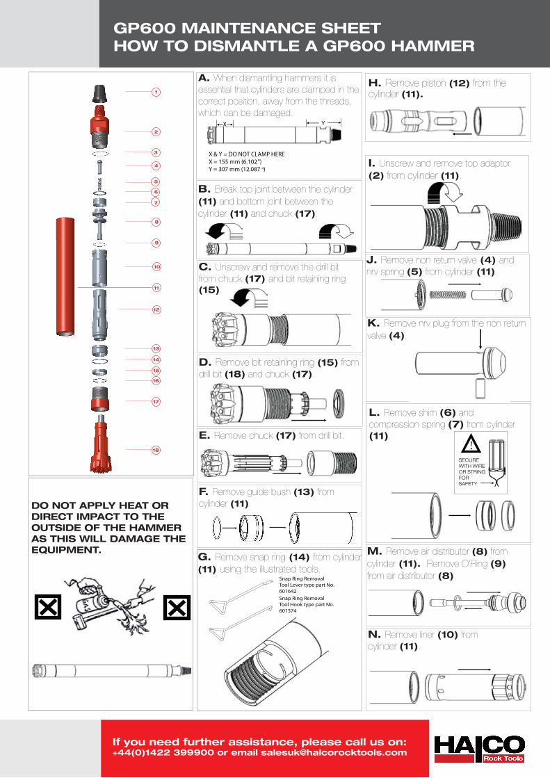
GP600 MAINTENANCE SHEET HOW TO DISMANTLE A GP600 HAMMER
H. Remove piston (12) from the cylinder (11).
A. When dismantling hammers it is essential that cylinders are clamped in the correct position, away from the threads, which can be damaged.
DO NOT APPLY HEAT ORDIRECT IMPACT TO THE OUTSIDE OF THE HAMMERAS THIS WILL DAMAGE THEEQUIPMENT.
B. Break top joint between the cylinder(11) and bottom joint between the cylinder (11) and chuck (17).
C. Unscrew and remove the drill bitfrom chuck (17) and bit retaining ring (15).
D. Remove bit retaining ring (15) fromdrill bit (18) and chuck (17).
E. Remove chuck (17) from drill bit.
G. Remove snap ring (14) from cylinder (11) using the illustrated tools.
I. Unscrew and remove top adaptor(2) from cylinder (11).
K. Remove nrv plug from the non return valve (4).
L. Remove shim (6) and compression spring (7) from cylinder(11).
M. Remove air distributor (8) fromcylinder (11). Remove O’Ring (9) from air distributor (8).
N. Remove liner (10) from cylinder (11).
X & Y = DO NOT CLAMP HEREX = 155 mm (6.102
")
Y = 307 mm (12.087"
)
X Y
Snap Ring Removal Tool Lever type part No. 601642Snap Ring RemovalTool Hook type part No.601574
J. Remove non return valve (4) and nrv spring (5) from cylinder (11).
!SECURE WITH WIREOR STRINGFOR SAFETY
F. Remove guide bush (13) from cylinder (11).