Embed Size (px)
Citation preview

Curriculum-2011
Curriculum Development Cell
GOVERNMENT POLYTECHNIC, NAGPUR. (An Autonomous Institute of Govt. of Maharashtra)
COURSE CURRICULUM
PROGRAMME: DIPLOMA IN ELECTRONICS AND TELECOMM./ELECTRICAL ENGG.
LEVEL NAME: BASIC TECHNOLOGY COURSES
COURSE CODE: WS 1302
COURSE TITLE: WORKSHOP PRACTICE
PREREQUISITE: NIL
TEACHING
SCHEME: TH :00; TU :00; PR :04; TOTAL CREDITS: 04 (Hrs/Week)
(1 CREDIT = 1 CLOCK HR.)
EVALUATION SCHEME: MARKS THEORY TUTORIAL/PRACTICAL TOTAL
TERM
EXAM
PROG
TEST
TOTAL PRACT
EXAM
TERM
WORK
ORAL
EXAM
MAX. --- --- --- NIL 50@ NIL 50
MIN. --- --- --- --- 20 --- 20
( # - External & Internal Assessment ; @ - Internal Assessment only ) TIME ALLOTTED FOR TERM EXAM : --- TIME ALLOTTED FOR PROGRESSIVE
TEST : ---
RATIONALE :
The knowledge of different hand tools and basic processes such as Smithy, Carpentry Fitting,
Filling, Welding and Plumbing is essential for technicians.
OBJECTIVES : The students will be able to -
Acquainted with various hand tools.
Able to use these hand tools
Familiar with various skills and techniques used in various trades.
Able to use these techniques in manufacturing processes
Able to develop the skills in manufacturing
SKILLS :
To develop attitude towards safety
To develop ability to select appropriate tools
To develop ability to handle tools.
To develop ability to operate the machines.
CONTENTS :
A. THEORY : NIL
SR. NO. CHAPTER MARKS HOURS
- NIL -
B. LIST OF PRACTICALS/LABORATORY EXPERIENCES/ASSIGNMENTS:
S.No. Title of Practical/Lab.Work/Assignments
1.
MACHINE SHOP :
Two job’s demonstration involving operations facing, plane turning, step turning, taper turning,
drilling, boring, square treading (internal & external)
2. WELDING :
Curriculum-2011
Curriculum Development Cell
One composite job individually involving operations-angle cutting, pipe cutting, M.S. flat
cutting, drilling and welding, soldering and brazing.
3. Demonstration of tools, equipments and machineries used in fitting shop.
4. Demonstration of tools, equipments and machineries used in smithy shop.
5. Demonstration of tools, equipments and machineries used in carpentry shop .
ASSESSMENT OF LABORATORY EXPERIENCES/ASSIGNMENTS :
Continuous assessment of Term Work .
(The student shall submit a journal and jobs on above work at the end of term.)
SUGGESTED IMPLEMENTATION STRATEGIES :
1. Demonstration
2. Models/ sample jobs
SUGGESTED LEARNING RESOURCES :
1. PRINT : Manuals/Journals.
2. NON PRINT : CDs / Charts / Models
C. SPECIFICATION TABLE :
Chapter
No. Job Area
Weightage
(Marks)
Distribution of Marks
Cognitive Psychomotor Affective Total
1. Machine shop 20 03 14 03 20
2. Welding shop 15 03 10 02 15
3. Fitting 05 05 00 00 05
4. Smithy 05 05 00 00 05
5. Carpentry 05 05 00 00 05
Total 50 21 24 05 50
D. REFERENCE & TEXT BOOKS:
S.N. Title Author, Publisher, Edition
and Year Of publication ISBN Number
1. A course in Workshop Technology B.S.Raghuwanshi; Dhanpat
Rai & sons, New Delhi ; 2006
2. Elements of Workshop
Technology
Hajra; Choudhary; Media
Promoters & Publishers
Pvt.Ltd. Mumbai.
3.
A Textbook of Manufacturing
Process (Workshop Tech.)
Gupta J.K., R.S.Khurmi
S.Chand & Co. New Delhi
81-219-3092-8
4. Workshop practice manual V.Kapoor; Dhanpat Rai &
sons, New Delhi ; 2006
E. LIST OF EXPERTS & TEACHERS WHO CONTRIBUTED FOR THIS CURRICULUM:
S.N. Name Designation Institute / Industry
1. Shri A.W.Wankhade Work shop superintendent Govt.Poly. Nagpur
2. Shri.G.F.Potbhare Principal NIT Polytechnic, Nagpur
(Member Secretary PBOS) (Workshop Supt.)
Curriculum-2011
Curriculum Development Cell
GOVERNMENT POLYTECHNIC, NAGPUR. (An Autonomous Institute of Govt. of Maharashtra)
COURSE CURRICULUM
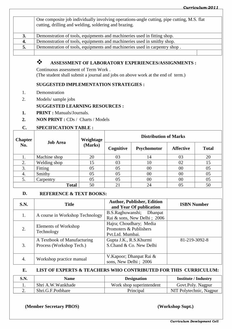
PROGRAMME : DIPLOMA IN CE/ME/EE/EC/CM/IT/AU/MT/PK.
LEVEL NAME : III - BASIC TECHNOLOGY COURSE
COURSE CODE : ME 1301
COURSE TITLE : ENGINEERING GRAPHICS
PREREQUISITE : NIL
TEACHING SCHEME : TH :02; TU :00; PR :04; TOTAL CREDITS: 06 (Hrs/Week)
(1 CREDIT = 1 CLOCK HR.)
EVALUATION SCHEME: MARKS THEORY TUTORIAL/PRACTICAL TOTAL
TERM
EXAM
PROG
TEST
TOTAL PRACT
EXAM
TERM
WORK
ORAL
EXAM
MAX. --- --- --- 50# 25@ NIL 75
MIN. --- --- --- 20 10 --- ---
( # - External & Internal Assessment ; @ - Internal Assessment only ) TIME ALLOTTED FOR TERM EXAM : --- TIME ALLOTTED FOR TERM END PR EXAM. : 02 HRS.
RATIONALE :
This is classified as Basic Technology Course. It describes the fundamentals, facts, concepts,
principles and techniques of Engineering Graphics. The course illustrates techniques of
drawing in an engineering field. The concepts of graphical language are used in expressing
the ideas, conveying the instructions, which are used in carrying out the jobs on the sites, shop
floor etc. It helps to develop the idea of visualizing the actual object or part on the basis of
drawings and blue prints. It is useful in understanding the Basic Technology and Applied
Technology Courses. The course illustrates the technique of graphics in actual practice. This
preliminary course aims at building a foundation for the further course in drawing and other
allied courses.
OBJECTIVES : The student shall be able to -
Draw geometrical figures, curves, sketches etc.
Coordinate the views of an object by using principles of orthographic projection.
Understand the concept of isometric projection.
Understand the techniques of application of drawing skills to actual practice.
Be familiar with various drawing codes, conventions and symbols as per Bureau of Indian
Standards.
SKILLS :
1. To develop ability to read & interpret the drawings.
2. To develop awareness of using IS convention for graphics.
3. To develop ability to visualize the given objects in space & reproduce the same.
4. To develop attitude of accuracy, precision and cleanliness in drawing the objects.

Curriculum-2011
Curriculum Development Cell
CONTENTS :
A. THEORY :
SR. NO. CHAPTER MARKS HOURS
1.
INTRODUCTION TO DRAWING
06 04
1.1 Use of different drawing instruments and equipment
1.2 Types of letters and numbers (single stroke vertical and inclined
letters and numbers only
1.3 Conventions of lines
1.4 Scales (reduced, enlarged and full size)- Plain scale, diagonal
scale, comparative scale, Vernier scale and scale of Chords
1.5 Redrawing
1.6 Loci of points
2.
ENGINEERING CURVES
10 06
2.1
To draw an ellipse by: i) Directrix - focus method ii)Arcs of
circles method iii) Rectangle method iv)Concentric circles
method
2.2 To draw parabola by i)Directrix - focus method ii) Rectangle
method
2.3
To draw hyperbola by i)Directrix – focus method ii) Passing
through a given point with reference to given asymptotes iii)
Transverse axis focus method
2.4 To draw involute of circle and polygon of maximum six sides
2.5 To draw cycloid, epi-cycloid and hypo-cycloid
2.6 To draw Archimedean spiral & Helix
3.
ORTHOGRAPHIC PROJECTIONS
12 08
3.1 Introduction to orthographic projections
3.2 First angle and Third angle method of projections
3.3 Conversion of simple pictorial views into orthographic views and
dimensioning techniques as per IS SP-46
4.
ISOMETRIC PROJECTIONS
10 05 4.1 Isometric scales,
4.2 Isometric views of simple object (plane surfaces, Planting
surfaces, rectangular, V, Trapezoidal slots)
5.
PROJECTIONS OF STRAIGHT LINES
06 04 5.1
Projections of straight lines inclined to one reference plane and
parallel to the other – limited to both ends in one quadrant.
6.
FREE HAND SKETCHES
06 05
6.1 Types of threads – Vee and square threads, left hand and right
hand threads
6.2 Bolts – square and hexagonal bolts, eye bolt
6.3
Types of nuts – square, hexagonal, wing, capstan, cap, flanged,
ring and dome nut
6.4 Locking arrangement – lock or check nut, split pin, slotted nut,
castle nut, sawn nut and grooved nut
6.5 Foundation bolts- Eye foundation bolt, Rag foundation bolt,
Lewis foundation bolt and Cotter foundation bolt
6.6 Riveted joints – Lap and butt joints with maximum three rows
per plate
Total 50 32
Curriculum-2011
Curriculum Development Cell
B.
LIST OF PRACTICALS/LABORATORY EXPERIENCES/ASSIGNMENTS:
S.No. Title of Practical/Lab.Work/Assignments Hrs.
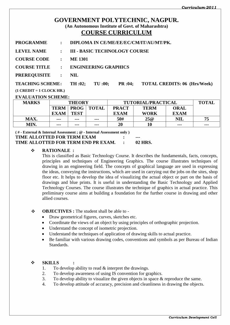
1.
Introduction to drawing - lines, lettering, numbers are to be drawn on sketch
book only and one problem each of topics and two problems of topic 1.5 of
chapter 1 on sheet (01 Sheet)
08
2.
Engineering Curves – four problems, one from topic 2.1, one from topic 2.2 &
2.3, one from topic 2.4 &2.5 and the fourth from topic 2.6 of chapter 2.
(01 Sheet)
12
3. Orthographic Projections – one problem using first angle method of projection
and another using third angle method of projection (01 Sheet) 12
4. Isometric Projections – one problem with plane surfaces & other with slot,
slanting surfaces (using natural scale and isometric scale) (01 Sheet) 12
5. Projections of Straight Lines – four problems, two using first angle method of
projection and the other two using third angle method of projection (01 Sheet) 12
6. Free Hand Sketches – any ten sketches covering all the topics under chapter 6
(01 Sheet) 08
Total 64
ASSESSMENT OF LABORATORY EXPERIENCES/ASSIGNMENTS :
Continuous assessment of Term Work and Term end practical examination ($).
AGB – Attendance and general behavior: 02
RSC – Regularity and sheet completion: 02
LWC – Line work and cleanliness: 03
OR – Oral :03
Total: 10
Note :-Total marks are converted into out of 25 and are considered as the term work marks.
#- For term end external practical examination there will be a paper for 50 marks and 02 Hrs
duration; external examiner will set a paper based on above content. Answer books (drawing
sheets of half imperial size) shall be assessed by external examiner only.
SUGGESTED IMPLEMENTATION STRATEGIES :
1. Lecture method
2. Improved lecture method.
3. Q & A technique.
4. Demonstration
SUGGESTED LEARNING RESOURCES :
1. PRINT : Text books/Reference books/Manuals/Journals.
2. NON PRINT : CDs / PPT / Transperencies / Charts / Models
C. SPECIFICATION TABLE : FOR PR. EXAMINATION
Chapter
No. Title of Chapter
Marks (1.5 x
Marks
allotted to
chapter)
Distribution of Marks
Knowledge Comprehension Application Total
1. Introduction to
Drawing 09 02 05 02 09
2. Engineering Curves 15 04 08 03 15
3. Orthographic
Projections 18 04 10 04 18
4. Isometric Projections 15 04 08 03 15
Curriculum-2011
Curriculum Development Cell
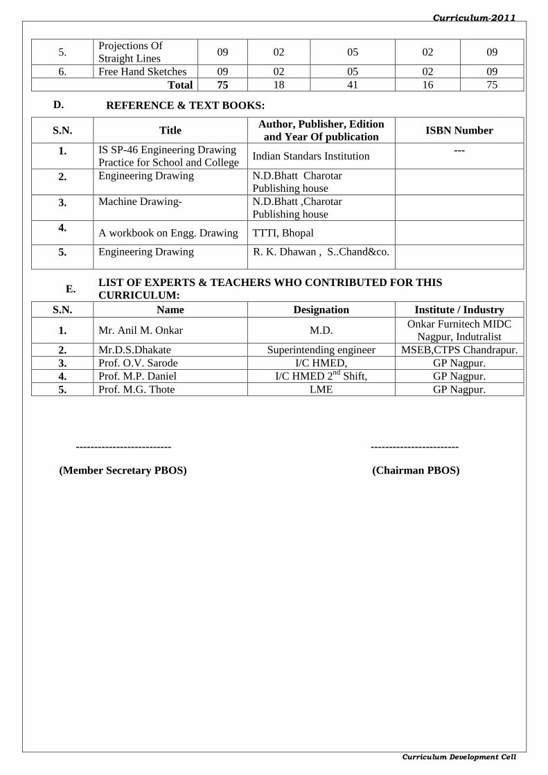
5. Projections Of
Straight Lines 09 02 05 02 09
6. Free Hand Sketches 09 02 05 02 09
Total 75 18 41 16 75
D. REFERENCE & TEXT BOOKS:
S.N. Title Author, Publisher, Edition
and Year Of publication ISBN Number
1. IS SP-46 Engineering Drawing
Practice for School and College Indian Standars Institution
---
2. Engineering Drawing
N.D.Bhatt Charotar
Publishing house
3. Machine Drawing-
N.D.Bhatt ,Charotar
Publishing house
4. A workbook on Engg. Drawing TTTI, Bhopal
5. Engineering Drawing R. K. Dhawan , S..Chand&co.
E. LIST OF EXPERTS & TEACHERS WHO CONTRIBUTED FOR THIS
CURRICULUM:
S.N. Name Designation Institute / Industry
1. Mr. Anil M. Onkar M.D. Onkar Furnitech MIDC
Nagpur, Indutralist
2. Mr.D.S.Dhakate Superintending engineer MSEB,CTPS Chandrapur.
3. Prof. O.V. Sarode I/C HMED, GP Nagpur.
4. Prof. M.P. Daniel I/C HMED 2nd
Shift, GP Nagpur.
5. Prof. M.G. Thote LME GP Nagpur.
-------------------------- ------------------------
(Member Secretary PBOS) (Chairman PBOS)
Curriculum-2011
Curriculum Development Cell
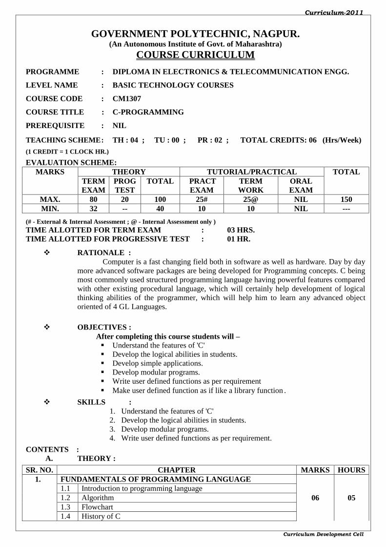
GOVERNMENT POLYTECHNIC, NAGPUR. (An Autonomous Institute of Govt. of Maharashtra)
COURSE CURRICULUM
PROGRAMME : DIPLOMA IN ELECTRONICS & TELECOMMUNICATION ENGG.
LEVEL NAME : BASIC TECHNOLOGY COURSES
COURSE CODE : CM1307
COURSE TITLE : C-PROGRAMMING
PREREQUISITE : NIL
TEACHING SCHEME : TH : 04 ; TU : 00 ; PR : 02 ; TOTAL CREDITS: 06 (Hrs/Week)
(1 CREDIT = 1 CLOCK HR.)
EVALUATION SCHEME: MARKS THEORY TUTORIAL/PRACTICAL TOTAL
TERM
EXAM
PROG
TEST
TOTAL PRACT
EXAM
TERM
WORK
ORAL
EXAM
MAX. 80 20 100 25# 25@ NIL 150
MIN. 32 -- 40 10 10 NIL ---
(# - External & Internal Assessment ; @ - Internal Assessment only ) TIME ALLOTTED FOR TERM EXAM : 03 HRS. TIME ALLOTTED FOR PROGRESSIVE TEST : 01 HR.
RATIONALE :
Computer is a fast changing field both in software as well as hardware. Day by day
more advanced software packages are being developed for Programming concepts. C being
most commonly used structured programming language having powerful features compared
with other existing procedural language, which will certainly help development of logical
thinking abilities of the programmer, which will help him to learn any advanced object
oriented of 4 GL Languages.
OBJECTIVES :
After completing this course students will –
Understand the features of 'C'
Develop the logical abilities in students.
Develop simple applications.
Develop modular programs.
Write user defined functions as per requirement
Make user defined function as if like a library function.
SKILLS :
1. Understand the features of 'C'
2. Develop the logical abilities in students.
3. Develop modular programs.
4. Write user defined functions as per requirement.
CONTENTS :
A. THEORY :
SR. NO. CHAPTER MARKS HOURS
1. FUNDAMENTALS OF PROGRAMMING LANGUAGE
06 05
1.1 Introduction to programming language
1.2 Algorithm
1.3 Flowchart
1.4 History of C
Curriculum-2011
Curriculum Development Cell
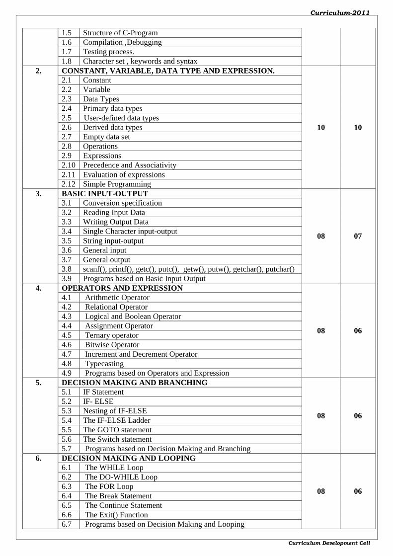
1.5 Structure of C-Program
1.6 Compilation ,Debugging
1.7 Testing process.
1.8 Character set , keywords and syntax
2. CONSTANT, VARIABLE, DATA TYPE AND EXPRESSION.
10 10
2.1 Constant
2.2 Variable
2.3 Data Types
2.4 Primary data types
2.5 User-defined data types
2.6 Derived data types
2.7 Empty data set
2.8 Operations
2.9 Expressions
2.10 Precedence and Associativity
2.11 Evaluation of expressions
2.12 Simple Programming
3. BASIC INPUT-OUTPUT
08 07
3.1 Conversion specification
3.2 Reading Input Data
3.3 Writing Output Data
3.4 Single Character input-output
3.5 String input-output
3.6 General input
3.7 General output
3.8 scanf(), printf(), getc(), putc(), getw(), putw(), getchar(), putchar()
3.9 Programs based on Basic Input Output
4. OPERATORS AND EXPRESSION
08 06
4.1 Arithmetic Operator
4.2 Relational Operator
4.3 Logical and Boolean Operator
4.4 Assignment Operator
4.5 Ternary operator
4.6 Bitwise Operator
4.7 Increment and Decrement Operator
4.8 Typecasting
4.9 Programs based on Operators and Expression
5. DECISION MAKING AND BRANCHING
08 06
5.1 IF Statement
5.2 IF- ELSE
5.3 Nesting of IF-ELSE
5.4 The IF-ELSE Ladder
5.5 The GOTO statement
5.6 The Switch statement
5.7 Programs based on Decision Making and Branching
6. DECISION MAKING AND LOOPING
08 06
6.1 The WHILE Loop
6.2 The DO-WHILE Loop
6.3 The FOR Loop
6.4 The Break Statement
6.5 The Continue Statement
6.6 The Exit() Function
6.7 Programs based on Decision Making and Looping
Curriculum-2011
Curriculum Development Cell
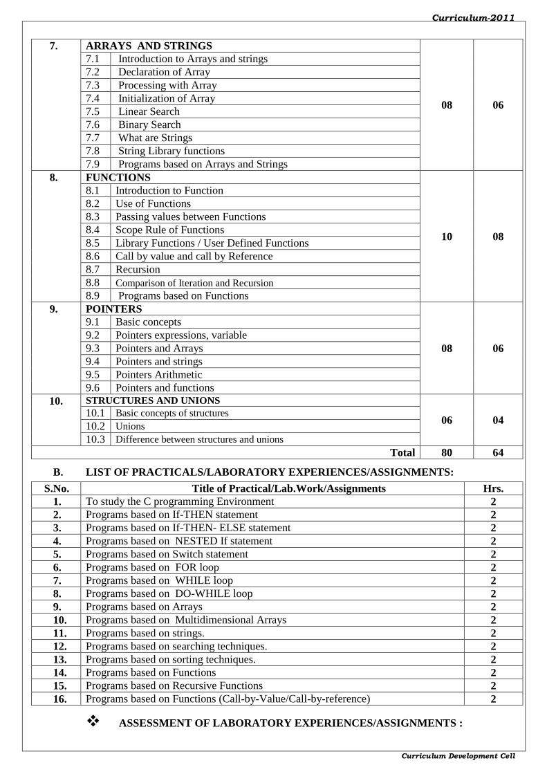
7. ARRAYS AND STRINGS
08 06
7.1 Introduction to Arrays and strings
7.2 Declaration of Array
7.3 Processing with Array
7.4 Initialization of Array
7.5 Linear Search
7.6 Binary Search
7.7 What are Strings
7.8 String Library functions
7.9 Programs based on Arrays and Strings
8. FUNCTIONS
10 08
8.1 Introduction to Function
8.2 Use of Functions
8.3 Passing values between Functions
8.4 Scope Rule of Functions
8.5 Library Functions / User Defined Functions
8.6 Call by value and call by Reference
8.7 Recursion
8.8 Comparison of Iteration and Recursion
8.9 Programs based on Functions
9. POINTERS
08 06
9.1 Basic concepts
9.2 Pointers expressions, variable
9.3 Pointers and Arrays
9.4 Pointers and strings
9.5 Pointers Arithmetic
9.6 Pointers and functions
10. STRUCTURES AND UNIONS
06 04 10.1 Basic concepts of structures
10.2 Unions
10.3 Difference between structures and unions
Total 80 64
B. LIST OF PRACTICALS/LABORATORY EXPERIENCES/ASSIGNMENTS:
S.No. Title of Practical/Lab.Work/Assignments Hrs.
1. To study the C programming Environment 2
2. Programs based on If-THEN statement 2
3. Programs based on If-THEN- ELSE statement 2
4. Programs based on NESTED If statement 2
5. Programs based on Switch statement 2
6. Programs based on FOR loop 2
7. Programs based on WHILE loop 2
8. Programs based on DO-WHILE loop 2
9. Programs based on Arrays 2
10. Programs based on Multidimensional Arrays 2
11. Programs based on strings. 2
12. Programs based on searching techniques. 2
13. Programs based on sorting techniques. 2
14. Programs based on Functions 2
15. Programs based on Recursive Functions 2
16. Programs based on Functions (Call-by-Value/Call-by-reference) 2
ASSESSMENT OF LABORATORY EXPERIENCES/ASSIGNMENTS :
Curriculum-2011
Curriculum Development Cell
Continuous assessment of Term Work and Term end oral/ practical examination.
SUGGESTED IMPLEMENTATION STRATEGIES :
1. Lecture method
2. Improved lecture method.
3. Q & A technique.
SUGGESTED LEARNING RESOURCES :
1. PRINT : Text books/Reference books
2. NON PRINT : CDs / PPT / Transperencies
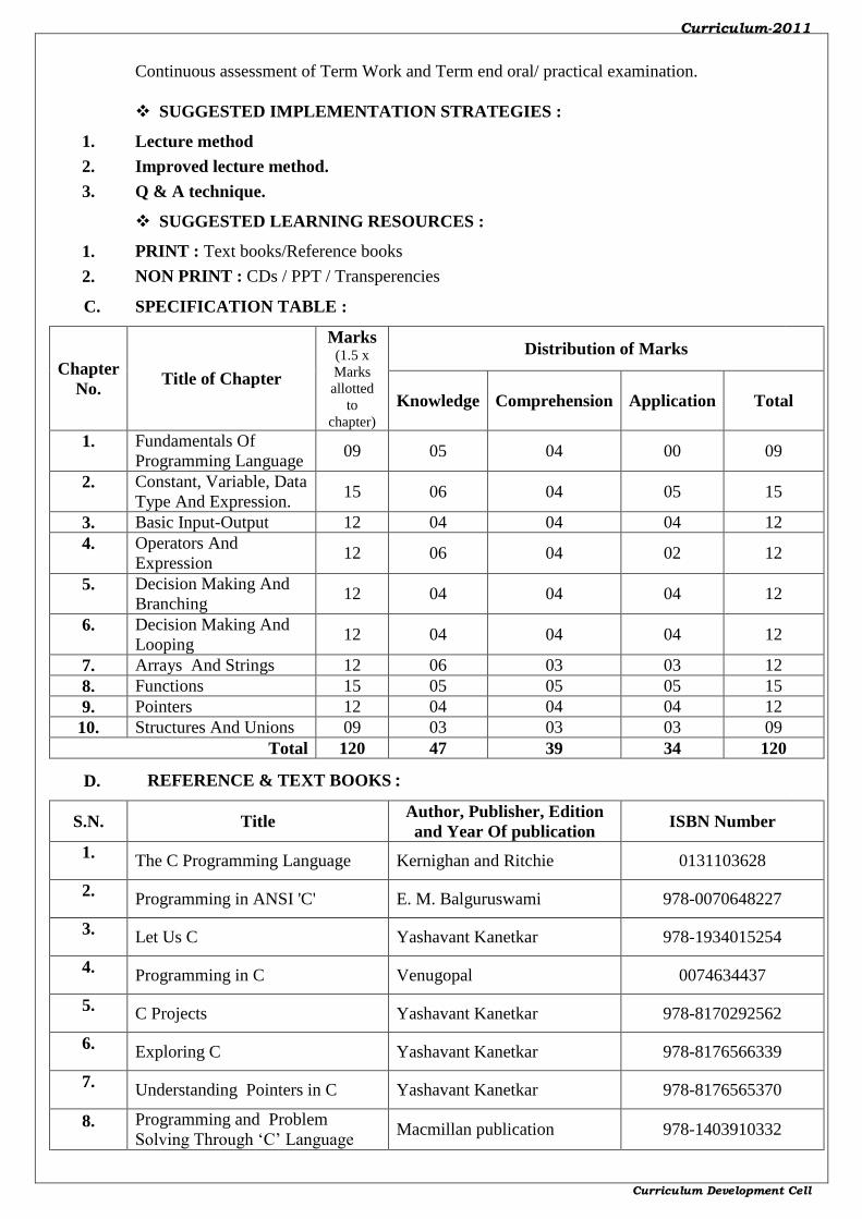
C. SPECIFICATION TABLE :
Chapter
No. Title of Chapter
Marks (1.5 x
Marks
allotted
to
chapter)
Distribution of Marks
Knowledge Comprehension Application Total
1. Fundamentals Of
Programming Language 09 05 04 00 09
2. Constant, Variable, Data
Type And Expression. 15 06 04 05 15
3. Basic Input-Output 12 04 04 04 12
4. Operators And
Expression 12 06 04 02 12
5. Decision Making And
Branching 12 04 04 04 12
6. Decision Making And
Looping 12 04 04 04 12
7. Arrays And Strings 12 06 03 03 12
8. Functions 15 05 05 05 15
9. Pointers 12 04 04 04 12
10. Structures And Unions 09 03 03 03 09
Total 120 47 39 34 120
D. REFERENCE & TEXT BOOKS:
S.N. Title Author, Publisher, Edition
and Year Of publication ISBN Number
1. The C Programming Language Kernighan and Ritchie 0131103628
2. Programming in ANSI 'C' E. M. Balguruswami 978-0070648227
3. Let Us C Yashavant Kanetkar 978-1934015254
4. Programming in C Venugopal 0074634437
5. C Projects Yashavant Kanetkar 978-8170292562
6. Exploring C Yashavant Kanetkar 978-8176566339
7. Understanding Pointers in C Yashavant Kanetkar 978-8176565370
8. Programming and Problem
Solving Through ‘C’ Language Macmillan publication 978-1403910332

Curriculum-2011
Curriculum Development Cell
E. LIST OF EXPERTS & TEACHERS WHO CONTRIBUTED FOR THIS CURRICULUM:
S.N. Name Designation Institute / Industry
1. Prof. RV. YENKAR HOD Govt. Polytechnic, Arvi
2. Prof. V.J. DONGRE Lecturer Govt. Polytechnic Nagpur
3. Prof. J.P. KELWADE Lecturer Govt. Polytechnic Nagpur
-------------------------- ------------------------
(Member Secretary PBOS) (Chairman PBOS)

Curriculum-2011
Curriculum Development Cell
GOVERNMENT POLYTECHNIC, NAGPUR. (An Autonomous Institute of Govt. of Maharashtra)
COURSE CURRICULUM
PROGRAMME : DIPLOMA IN EC/IT/CM
LEVEL NAME : BASIC TECHNOLOGY COURSES
COURSE CODE : EE1302
COURSE TITLE : ELECTRICAL ENGG.
PREREQUISITE : NIL
TEACHING SCHEME : TH :04; TU : 00; PR :02; TOTAL CREDITS: 06 (Hrs/Week)
(1 CREDIT = 1 CLOCK HR.)
EVALUATION SCHEME: MARKS THEORY TUTORIAL/PRACTICAL TOTAL
TERM
EXAM
PROG
TEST
TOTAL PRACT
EXAM
TERM
WORK
ORAL
EXAM
MAX. 80 20 100 --- 25@ - 125
MIN. 32 -- 40 --- 10 - ---
(# - External &Internal Assessment only; @ - Internal Assessment ;) TIME ALLOTTED FOR TERM EXAM : 03 HRS. TIME ALLOTTED FOR PROGRESSIVE TEST : 01 HR.
RATIONALE :
This course is classified under basic technology course. Basic
technology course describes the facts, concepts, principles & techniques of scientific
investigation in Engineering field. This course describes the basic facts, concepts &
principles for the understanding of basic elementary knowledge related to electrical area,
which are commonly used in any discipline of Engineering & Technology.
OBJECTIVES :
After completing this course students will be able to -
1. To understand the concept of electrical safety.
2. To understand the concept of different electrical terminology used in electrical
engineering.
3. To understand different principle and basic laws in electrical systems / sources.
4. To understand elementary working knowledge of basic instruments, A.C/D.C sources,
transformers and motors.
SKILLS : Student will be able -
1. To connect basic electrical measuring instruments in the circuit.
2. To record the readings of various types of meters like voltmeter, ammeter, wattmeter,
multi-meter, tong tester etc.
3. To interpret electrical circuit diagrams & Wiring layout diagrams.
4. To Select & connect proper electrical drives and meters
CONTENTS :
A. THEORY :
SR. NO. CHAPTER MARKS HOURS
1. ELECTRICL SAFETY 05 04

Curriculum-2011
Curriculum Development Cell
1.1
Electrical Safety, Causes of accidents, General safety rules,
Concept of electrical shock, Effect of electric shock, Method of
removing electrocuted person, Safety signs and symbols.
1.2 Artificial respiration-schaefer’s method, silvester’s method, mouth
to mouth respiration.
1.3 First Aid
1.4
Fire, Causes of Fire, Basic ways of extinguishing the fire
Classification of fire, Class A, B,C, D, Fire fighting equipments,
fire extinguishers, and their types .
1.5 Necessity of earthing- pipe and plate earthing, methods of reducing
earth resistance.
2.
FUNDAMENTALS OF ELECTRICITY
15 12
2.1 Concept of electric charge, current, voltage drop, EMF, potential
difference, Direction of current and their SI units.
2.2
Resistance, unit of resistance, Law of resistance, Effect of
temperature on resistance, temperature coefficient of resistance,
Ohms law. (Numerical problems based on it.)
2.3 Conductors, insulators, semiconductors, dielectric materials used in
electrical system.
2.4
Work, power, energy and their SI units, Joule’s law, Relation
between H.P and watts, Kwh and Kcal, cost of electrical energy.
(Numerical problems based on it.) . Measurement of current,
voltage, power in DC and single-phase AC system with connection
diagram.
2.5
BIS symbols as per IS:2032 related to circuit elements, variable
resistors, rotating machines, transformers, electrical meters and
miscellaneous apparatus.
2.6
Concept of generation, transmission and distribution of electrical
power, line diagram of AC power flow in supply systems, voltage
levels at various stages in power system
2.7
Concept of DC voltage & current. Concept of D.C. power supplies,
D.C. generator, rectifier, D.C. batteries. Types, construction &
applications of Lead acid battery.
3.
D. C. CIRCUITS
09 07
3.1
Resistance in series, properties of series circuit, voltage distribution
in series circuit, equivalent resistance of series circuit, Applications
of series circuits.
3.2
Resistance in parallel, properties of parallel circuit, current
distribution in parallel circuit, equivalent resistance of parallel
circuit, Applications of parallel circuits.
3.3
Series-parallel combination, Equivalent resistance of series-parallel
combination. Application of ohm’s law for simple DC circuits
(Numerical problems based on it.)
3.4 Kirchhoff’s current and voltage law. Sign convention.
3.5 Concept of voltage source and current source (Ideal and practical),
Source transformation.
3.6 Application of Kirchhoff’s laws for solving circuits.
4.
ELECTROSTATICS
09 07 4.1
Coulombs law of Electrostatics, Absolute and relative permittivity,
Concept of electric field, electric flux, electric intensity, electric
flux density, electric potential, potential gradient, dielectric
strength.
4.2 Capacitance, dielectric constant, capacitance of parallel plate
capacitor, capacitance in series and parallel and source of

Curriculum-2011
Curriculum Development Cell
capacitance in electrical systems. Charging & discharging of
capacitor, Dielectric loss.
(Numerical problems based on it).
4.3 Types of capacitor and their application
5.
ELECROMAGNETISM
09 07 5.1
Faraday’s Law of electromagnetic induction, Direction of induced
EMF and current, Lenz’s Law, Induced EMF, Dynamically
induced EMF, statically induced EMF, self Inductance, Mutual
Inductance, Fleming’s right hand rule, Energy stored in inductor,
rise and decay of current through inductor.
5.2 Interaction between magnetic fields, force on current carrying
conductor.
6.
A. C. FUNDAMENTALS
09 07
6.1 Generation of alternating voltage- single phase and three-phase.
6.2
Important terminology such as- waveform, instantaneous value,
cycle, time period, frequency, amplitude, Relation between time
period and frequency, angular velocity and frequency, frequency
and speed.
6.3 Maximum, average and R.M.S. value of sinusoidal waveform, form
factor and peak factor. (Numerical problems based on above topic).
6.4
A.C. Voltage applied to pure resistor, pure inductor, and pure
capacitor. Concept of reactance, Impedance and power factor,
power in single-phase circuits. (Simple problems)
6.5 R-L, R-C and R-L-C series circuits, series resonance. Q-
factor.(Simple problems)
6.6 Types of loads. Standard single phase and three-phase distribution
supply system.
7.
TRANSFORMER
09 07 7.1
Single phase Transformer – Definition, principle of operation, types
of transformer, EMF equation (No derivation), transformation ratio,
KVA rating of transformer, voltage regulation and efficiency
(Simple Numerical problem based on above topic).
7.2 Auto-transformer, Isolation transformer, CT and PT.
8.
MOTORS
15 13
8.1 Broad classification of A.C & D.C motor.
8.2
D.C. motor: Principle of operation, Types – shunt, series and
compound motor. Applications, speed control of D.C. shunt and
series motor, starters for DC motor.
8.3
Induction motor - Three-phase Induction motor – Principle of
operation, construction, classification of 3-phase Induction motor,
speed control methods of 3-phase induction motor, its application.
Method of reversing the direction of rotation of motor, starters for
three-phase motors.
8.4
Single-phase Induction motor – Principle of operation,
classification of single-phase Induction motor, speed control,
applications. Method of reversing the direction of rotation of motor.
8.5 Synchronous motor- Principle of operation and its application in
electronics industries.
8.6 Stepper motor - Principle of operation and its application.
(No Numerical on topic 8)
Total 80 64

Curriculum-2011
Curriculum Development Cell
B. LIST OF PRACTICALS/LABORATORY EXPERIENCES/ASSIGNMENTS:
S.No. Title of Practical/Lab.Work/Assignments Hrs.
1. To connect voltmeter, ammeter and wattmeter in electrical circuit. 2
2. To Verify ohms law. 2
3. To determine temperature coefficient of resistance of conductors like copper,
nichrome etc. 2
4. To verify the total resistance of series circuit. 2
5. To verify the total resistance of parallel circuit. 2
6. To verify Kirchhoff’s laws. (KCL & KVL) 2
7.
To use test lamps for single-phase and three –phase supply. Use of test lamp for
earth continuity. Use of tester on single-phase supply.
2
8. To find voltage current relationship in R-C series circuit and to determine the power
factor of the circuit. 4
9. To verify voltage & current ratio of single- phase transformer. 4
10. To reverse the directions of rotation of DC shunt motor. 2
11. To reverse the direction of rotation of three-phase induction motor. 4
12. To reverse the direction of rotation single -phase capacitor start motor. 2
13. To study the constructional details of steeper motor. 2
TOTAL 32
Note:- Any Twelve experiments to be performed
ASSESSMENT OF LABORATORY EXPERIENCES/ASSIGNMENTS :
Continuous assessment of Term Work and Term end oral/ practical examination.
SUGGESTED IMPLEMENTATION STRATEGIES :
1. Lecture method
2. Improved lecture method.
3. Q & A technique.
4. Demonstration
5. Case study
6. Seminars
7. Field visit
SUGGESTED LEARNING RESOURCES :
1. PRINT : Text books/Reference books/Manuals/Journals.
2. NON PRINT : CDs / PPT / Transperencies / Charts / Models
C. SPECIFICATION TABLE :
Chapter
No. Title of Chapter
Marks (1.5 x
Marks
allotted to
chapter)
Distribution of Marks
Knowledge Comprehension Application Total

Curriculum-2011
Curriculum Development Cell
1. Electrical safety 06 06 00 00 06
2. Fundamentals of
Electricity
22 04 12 06 22
3. DC Circuits 14 02 06 06 14
4. Electrostatics 14 02 12 00 14
5. Electromagnetism 14 02 06 06 14
6. AC Fundamentals 14 02 06 06 14
7. Transformer 14 08 06 00 14
8. Motors 22 04 12 06 22
Total 120 30 60 30 120
D. REFERENCE & TEXT BOOKS:
S.N. Title Author, Publisher, Edition
and Year Of publication ISBN Number
1. Principle of Electrical
Engineering and Electronics
V.K.Mehta, S.Chand &
Company Ltd., Reprint, 1996
ISBN:81-219-1053-6
2. A Text Book Of Electrical
Technology Vol-I
B.L.Theraja, A.K.Theraja,
S.Chand & Co Ltd.,
Reprint,2006
ISBN: 81-219-2440-5
3. Basic Electrical Engineering Nagrath and Kothari
4.
Experiments in Basic Electrical
Engineering
S.K.Bhattacharya and
K.M.Rastogi., New Age
International Publisher,
Reprint, 2009.
ISBN:978-81-224-1042-6
5. A Text Book on laboratory courses
in Electrical Engineering
S.G.Tarnekar and
P.K.Kharbanda, S.Chand &
Company Ltd., Third, 1990
ISBN: 81-219-
E. LIST OF EXPERTS & TEACHERS WHO CONTRIBUTED FOR THIS CURRICULUM:
S.N. Name Designation Institute / Industry
1. A.M.Arekar I/C, Head of Electrical
Engineering
Government Polytechnic,
Nagpur.
2. R.I.Kamble Lecturer in Electrical
Engineering
Government Polytechnic,
Nagpur.
3. M.C.Musale Lecturer in Electrical
Engineering
Government Polytechnic,
Nagpur.
4. Smt. J.D.Waghamare Lecturer in Electrical
Engineering
Government Polytechnic,
Nagpur.
5. R.D.Khandar Lecturer in Electrical
Engineering
Government Polytechnic,
Nagpur.
6. G.V.Gotmare Lecturer in Electrical
Engineering
Government Polytechnic,
Nagpur.
-------------------------- ------------------------
(Member Secretary PBOS) (Chairman PBOS)
Curriculum-2011
Curriculum Development Cell
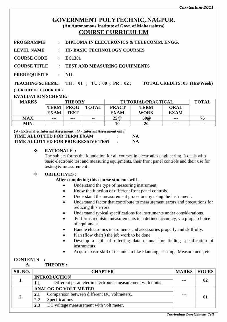
GOVERNMENT POLYTECHNIC, NAGPUR. (An Autonomous Institute of Govt. of Maharashtra)
COURSE CURRICULUM
PROGRAMME : DIPLOMA IN ELECTRONICS & TELECOMM. ENGG.
LEVEL NAME : III- BASIC TECHNOLOGY COURSES
COURSE CODE : EC1301
COURSE TITLE : TEST AND MEASURING EQUIPMENTS
PREREQUISITE : NIL
TEACHING SCHEME : TH : 01 ; TU : 00 ; PR : 02 ; TOTAL CREDITS: 03 (Hrs/Week)
(1 CREDIT = 1 CLOCK HR.)
EVALUATION SCHEME: MARKS THEORY TUTORIAL/PRACTICAL TOTAL
TERM
EXAM
PROG
TEST
TOTAL PRACT
EXAM
TERM
WORK
ORAL
EXAM
MAX. --- --- -- 25@ 50@ --- 75
MIN. --- --- -- 10 20 --- ---
( # - External & Internal Assessment ; @ - Internal Assessment only ) TIME ALLOTTED FOR TERM EXAM : NA TIME ALLOTTED FOR PROGRESSIVE TEST : NA
RATIONALE :
The subject forms the foundation for all courses in electronics engineering. It deals with
basic electronic test and measuring equipments, their front panel controls and their use for
testing & measurement .
OBJECTIVES :
After completing this course students will –
Understand the type of measuring instrument.
Know the function of different front panel controls.
Understand the measurement procedure by using the instrument.
Understand factor that contribute to measurement errors and precautions for
reducing this errors.
Understand typical specifications for instruments under considerations.
Performs requisite measurements to a defined accuracy, via proper choice
of equipment.
Handle electronics instruments and accessories properly and skillfully.
Plan (flow chart ) the job work to be done.
Develop a skill of referring data manual for finding specification of
instruments.
Acquire basic skill of technician like Planning, Testing, Measurement, etc.
CONTENTS :
A. THEORY :
SR. NO. CHAPTER MARKS HOURS
1. INTRODUCTION
--- 02 1.1 Different parameter in electronics measurement with units.
2.
ANALOG DC VOLT METER
---
01
2.1 Comparison between different DC voltmeters.
2.2 Specifications
2.3 DC voltage measurement with volt meter.

Curriculum-2011
Curriculum Development Cell
3.
ANALOG DC AMMETER ---
01 3.1 Comparison between different DC voltmeters
3.2 Specifications
4.
ANALOG MULTIMETER
---
01
4.1 Specifications
4.2 Operating controls & their functions.
4.3 List of applications.
5.
DIGITAL MULTIMETER
---
02
5.1 Specifications
5.2 Operating controls & their functions.
5.3 List of applications.
6.
LCR Q METER
---
02
6.1 Specifications
6.2 Front panel controls & their functions.
6.3 List of applications.
7.
REGULATED POWER SUPPLY
---
01
7.1 Specifications
7.2 Front panel controls & their functions.
7.3 List of applications
8.
FUNCTION GENERATOR
---
02
8.1 Specifications & list of applications.
8.2 Front panel controls & their functions.
8.3 List of applications
9.
CATHODE RAY OSCILLOSCOPE
---
02
9.1 Specifications & list of applications.
9.2 Front panel controls & their functions.
9.3 Measurement of amplitude and frequency.
10.
DIGITAL STORAGE CATHODE RAY OSCILLOSCOPE ---
02 10.1 Specifications & list of applications.
10.2 Front panel controls & their functions.
--- 16
B. LIST OF PRACTICALS/LABORATORY EXPERIENCES/ASSIGNMENTS:
S.No. Title of Practical/Lab.Work/Assignments Hrs.
1. To list the different parameter in Electronics measurement with units. 02
2. To list the different electronics test & measuring instruments with their application. 02
3.
Analog DC volt meter
DC voltage measurement with volt meter.
Precautions while connecting the volt meter.
02
4.
Analog DC Ammeter
DC current measurement with ammeter
Precaution while connecting the ammeter.
02
5.
Analog Multimeter.
DC and AC voltage measurement.
DC and AC current measurement.
Different resistance measurement.
Component testing.(resistor, capacitor, transistor)
04
6.
Digital Multimeter
DC and AC voltage measurement.
DC and AC current measurement.
Different resistance measurement.
Component testing.(diode, capacitor, transistor) & continuity
tester.
04

Curriculum-2011
Curriculum Development Cell
7.
LCR Q meter
Different resistance measurement.
Precision measurement of component –Resistor ,capacitor,
inductor
02
8. Regulated power supply
Setting of voltage & current limit with controls. 02
9.
Function generator.
Different function selection.
Amplitude & Frequency changing with course and fine
control.
Effect of DC shift.
04
10.
Cathode Ray Oscilloscope
Specifications & list of applications.
Front panel controls & their functions.
Observing different waveforms.
Measurement of amplitude and frequency.
04
11.
Digital Storage cathode ray oscilloscope.
Specifications & list of applications.
Front panel controls & their functions.
Observing the low frequency signals with storage facility .
Measurement of amplitude and frequency
04
Total 32
ASSESSMENT OF LABORATORY EXPERIENCES/ASSIGNMENTS :
Continuous assessment of Term Work and Term end oral/ practical examination.
SUGGESTED IMPLEMENTATION STRATEGIES :
1. Lecture method
2. Improved lecture method.
3. Q & A technique.
4. Demonstration
5. Case study
6. Seminars
7. Field visit
SUGGESTED LEARNING RESOURCES :
1. PRINT : Text books/Reference books/Manuals/Journals.
2. NON PRINT : CDs / PPT / Transperencies / Chartes / Models
C. SPECIFICATION TABLE : (NOT APPLICABLE)
Chapter
No. Title of Chapter
Marks (1.5 x
Marks
allotted to
chapter)
Distribution of Marks
Knowledge Comprehension Application Total
NOT APPLICABLE
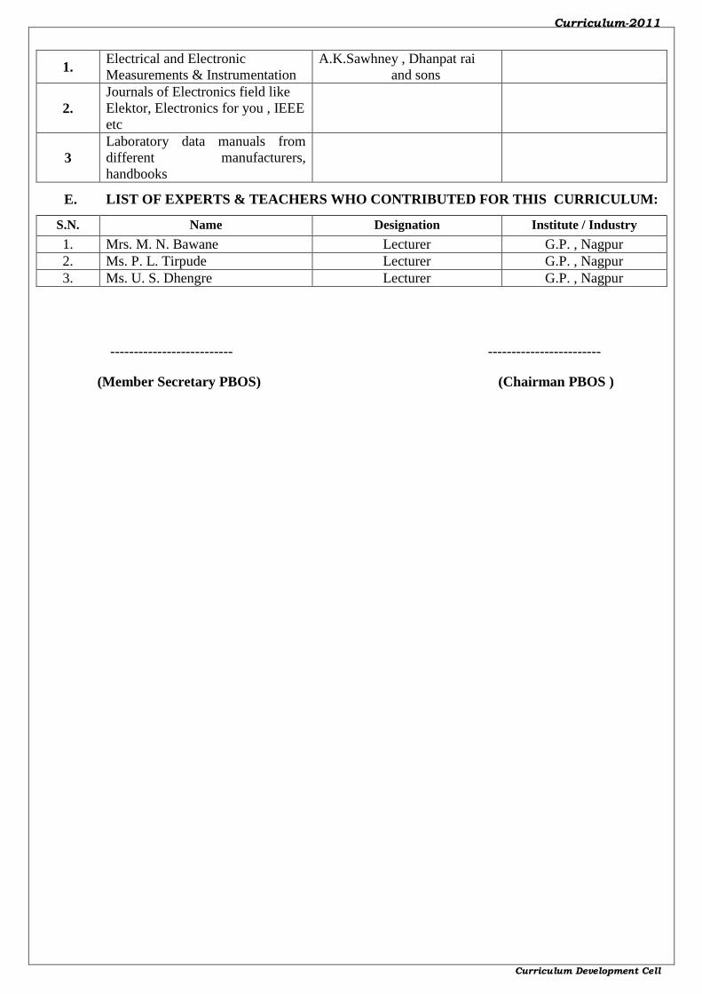
D. REFERENCE & TEXT BOOKS:
S.N. Title Author, Publisher, Edition
and Year Of publication ISBN Number
Curriculum-2011
Curriculum Development Cell
1. Electrical and Electronic
Measurements & Instrumentation
A.K.Sawhney , Dhanpat rai
and sons
2.
Journals of Electronics field like
Elektor, Electronics for you , IEEE
etc
3
Laboratory data manuals from
different manufacturers,
handbooks
E. LIST OF EXPERTS & TEACHERS WHO CONTRIBUTED FOR THIS CURRICULUM:
S.N. Name Designation Institute / Industry
1. Mrs. M. N. Bawane Lecturer G.P. , Nagpur
2. Ms. P. L. Tirpude Lecturer G.P. , Nagpur
3. Ms. U. S. Dhengre Lecturer G.P. , Nagpur
-------------------------- ------------------------
(Member Secretary PBOS) (Chairman PBOS )

Curriculum-2011
Curriculum Development Cell
GOVERNMENT POLYTECHNIC, NAGPUR. (An Autonomous Institute of Govt. of Maharashtra)
COURSE CURRICULUM
PROGRAMME : DIPLOMA IN ELECTRONICS & TELECOMM. ENGG.
LEVEL NAME : BASIC TECHNOLOGY COURSES
COURSE CODE : EC1302
COURSE TITLE : BASIC ELECTRONICS
PREREQUISITE : NIL
TEACHING SCHEME : TH : 04; TU :NIL; PR :02; TOTAL CREDITS: 06 (Hrs/Week)
(1 CREDIT = 1 CLOCK HR.)
EVALUATION SCHEME: MARKS THEORY TUTORIAL/PRACTICAL TOTAL
TERM
EXAM
PROG
TEST
TOTAL PRACT
EXAM
TERM
WORK
ORAL
EXAM
MAX. 80 20 100 --- 25@ 25@ 150
MIN. 32 -- 40 --- 10 10 ---
( # - External & Internal Assessment ; @ - Internal Assessment only ) TIME ALLOTTED FOR TERM EXAM : 03 HRS. TIME ALLOTTED FOR PROGRESSIVE TEST : 01 HR.
RATIONALE :
The subject forms the foundation for all courses in electronics engineering. It s
fundamental circuits used in all electronic circuits. This course prepares the student’s
understanding in basic electronic devices, their ratings and applications.
OBJECTIVES :
After completing this course students will be able to–
1. Understand the construction and characteristic of semiconductor devices.
2. Understand the use of semiconductor devices in electronic circuits.
3. Understand the working of simple electronic circuits.
SKILLS :
1.Understand the construction and characteristic of semiconductor devices.
2. Understand the use of semiconductor devices in electronic circuits.
3. Knowledge of concept of working of simple electronic circuits.
4. Use of CRO , Function Generator & Multimeter for measurements
CONTENTS :
A. THEORY :
SR. NO. CHAPTER MARKS HOURS
1. SEMICONDUCTOR THEORY & P-N JUNCTION DIODE
08
08
1.1 Energy levels, energy bands, important energy bands in solids,
semiconductors. Bonds in semiconductor.
1.2 Commonly used semiconductor - Germanium, Silicon. Intrinsic
semiconductor.
1.3 Extrinsic semiconductors. P-type and N-type semiconductors.
1.4 PN junction. Formation of PN junction.
1.5 Forward and reverse biasing. V-I characteristic of PN junction
diode,

Curriculum-2011
Curriculum Development Cell
1.6 specification of diode,
1.7 working of various diodes- PIN diodes ,
1.8 Varactor diodes, Tunnel diodes
2. RECTIFIERS
10
08
2.1 Definition and types of rectifier. Circuit details, operating
principle, advantages and disadvantages of half wave
2.2 Circuit details, operating principle, advantages and disadvantages
of half wave and full wave rectifiers
2.3
Definition of peak inverse voltage (PIV), ripple factor, form
factor, rectification efficiency and transformer utilization factor
(TUF)
2.4 Comparison of half and full wave rectifier
3. FILTER CIRCUITS
06
04
3.1 Necessity and types of filter.
3.2 Circuit diagram, operating principle and output waveforms of
series inductor,
3.3 shunt capacitor, chock input (LC)
3.4 capacitor ( PI) filters.
4. ZENER DIODE
06
04
4.1 Types of reverse breakdown- zener and avalanche breakdown and
their comparison.
4.2 Principle of operation, characteristics , specifications and
applications of zener diode.
4.3
specifications –Zener voltage,power dissipation, breakdown
current, dynamic resistance & maximum reverse current
and applications of zener diode
4.4 Zener diode as a voltage regulator.
5. BJT
16 12
5.1 Structure of PNP and NPN Bipolar Junction Transistor (BJT).
5.2 Construction, operating principle and symbol of PNP and NPN
transistor.
5.3 CB ,CE and CC transistor configuration
5.4 Input and output characteristics of transistor in CB and CE
configuration.
5.5
Definition of transistor parameter-Input resistance, output
resistance, current gains alpha and beta. Relation between current
gains (Alpha and Beta), leakage currents.
5.6 Application and specifications of transistors-
Vcesat,Icmax,Vceo,Iceo,Vcebreakdown,power dissipation.
5.7 Comparison of CB, CE and CC. Advantages of CE configuration.
5.8 Testing of transistor and identification of terminals of transistors.
6. TRANSISTOR BIASING AND STABILIZATION
12 10
6.1 Faithful amplification. Transistor biasing. Stabilization.
6.2 Stabilization. Need for bias stabilization.
6.3 Methods of transistor biasing – fixed bias,
6.4 Biasing with feedback resistor,
6.5 Base bias with emitter feedback,
6.6 Voltage divider bias.
Curriculum-2011
Curriculum Development Cell
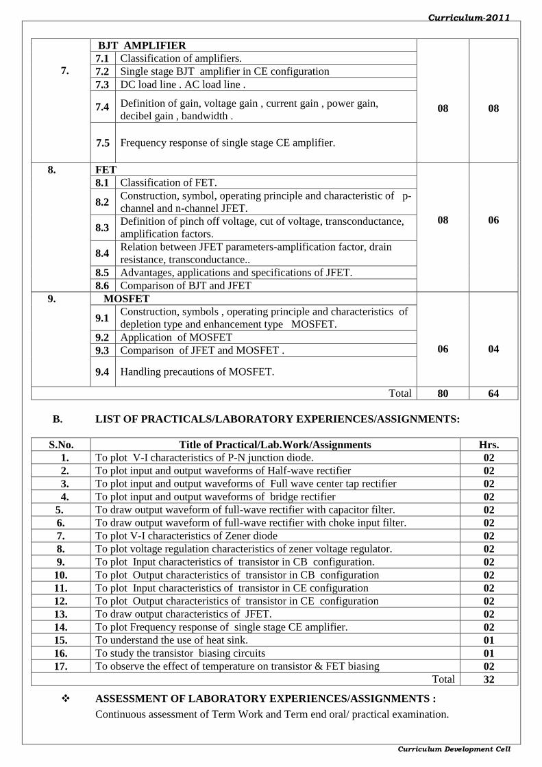
7.
BJT AMPLIFIER
08
08
7.1 Classification of amplifiers.
7.2 Single stage BJT amplifier in CE configuration
7.3 DC load line . AC load line .
7.4 Definition of gain, voltage gain , current gain , power gain,
decibel gain , bandwidth .
7.5 Frequency response of single stage CE amplifier.
8. FET
08
06
8.1 Classification of FET.
8.2 Construction, symbol, operating principle and characteristic of p-
channel and n-channel JFET.
8.3 Definition of pinch off voltage, cut of voltage, transconductance,
amplification factors.
8.4 Relation between JFET parameters-amplification factor, drain
resistance, transconductance..
8.5 Advantages, applications and specifications of JFET.
8.6 Comparison of BJT and JFET
9. MOSFET
06
04
9.1 Construction, symbols , operating principle and characteristics of
depletion type and enhancement type MOSFET.
9.2 Application of MOSFET
9.3 Comparison of JFET and MOSFET .
9.4 Handling precautions of MOSFET.
Total 80 64
B. LIST OF PRACTICALS/LABORATORY EXPERIENCES/ASSIGNMENTS:
S.No. Title of Practical/Lab.Work/Assignments Hrs.
1. To plot V-I characteristics of P-N junction diode. 02
2. To plot input and output waveforms of Half-wave rectifier 02
3. To plot input and output waveforms of Full wave center tap rectifier 02
4. To plot input and output waveforms of bridge rectifier 02
5. To draw output waveform of full-wave rectifier with capacitor filter. 02
6. To draw output waveform of full-wave rectifier with choke input filter. 02
7. To plot V-I characteristics of Zener diode 02
8. To plot voltage regulation characteristics of zener voltage regulator. 02
9. To plot Input characteristics of transistor in CB configuration. 02
10. To plot Output characteristics of transistor in CB configuration 02
11. To plot Input characteristics of transistor in CE configuration 02
12. To plot Output characteristics of transistor in CE configuration 02
13. To draw output characteristics of JFET. 02
14. To plot Frequency response of single stage CE amplifier. 02
15. To understand the use of heat sink. 01
16. To study the transistor biasing circuits 01
17. To observe the effect of temperature on transistor & FET biasing 02
Total 32
ASSESSMENT OF LABORATORY EXPERIENCES/ASSIGNMENTS :
Continuous assessment of Term Work and Term end oral/ practical examination.

Curriculum-2011
Curriculum Development Cell
SUGGESTED IMPLEMENTATION STRATEGIES :
1. Lecture method
2. Improved lecture method.
3. Q & A technique.
4. Demonstration
5. Case study
SUGGESTED LEARNING RESOURCES :
1. PRINT : Text books/Reference books/Manuals/Journals.
2. NON PRINT : CDs / PPT / Transperencies / Charts / Models
C. SPECIFICATION TABLE :
Chapter
No. Title of Chapter
Marks (1.5 x
Marks
allotted to
chapter)
Distribution of Marks
Knowledge Comprehension Application Total
1. Semiconductor
Theory & P-N
junction Diode
18 10 05 03 18
2. Rectifiers 15 05 05 05 15
3. Filter circuits 09 03 04 02 09
4. Zener Diode 09 03 03 03 09
5. BJT 24 10 10 04 24
6. Transistor Biasing
and Stabilization 15 05 05 05 15
7. BJT Amplifier 09 03 03 03 09
8. FET 12 04 04 04 12
9. MOSFET 09 03 03 03 09
Total 120 46 42 32 120
D. REFERENCE & TEXT BOOKS:
S.N. Title Author, Publisher, Edition
and Year Of publication ISBN Number
1. Principles of Electronics V.K.Mehta,S.Chand
2. Electronics Devices & Circuits Allan Mottershed,Tata Mc
Graw Hill
3. Electronic Principles A.P. Malvino, Tata Mc Graw
Hill
4. Applied Electronics S.L.Sedha, S.Chand
5. Basic Electronics Grob, Tata Mc Graw Hill
6. Electronics Devices & Circuits S.Salivahanan, Tata Mc Graw
Hill
E. LIST OF EXPERTS & TEACHERS WHO CONTRIBUTED FOR THIS
CURRICULUM: S.N. Name Designation Institute / Industry
1. Ms.M.N.Bawane Sr.Lecturer G. P. Nagpur
2. Miss.P.L.Tirpude Lecturer G. P. Nagpur
(Member Secretary PBOS) (Chairman PBOS)
Curriculum-2011
- 25 -
GOVERNMENT POLYTECHNIC, NAGPUR. (An Autonomous Institute of Govt. of Maharashtra)
COURSE CURRICULUM
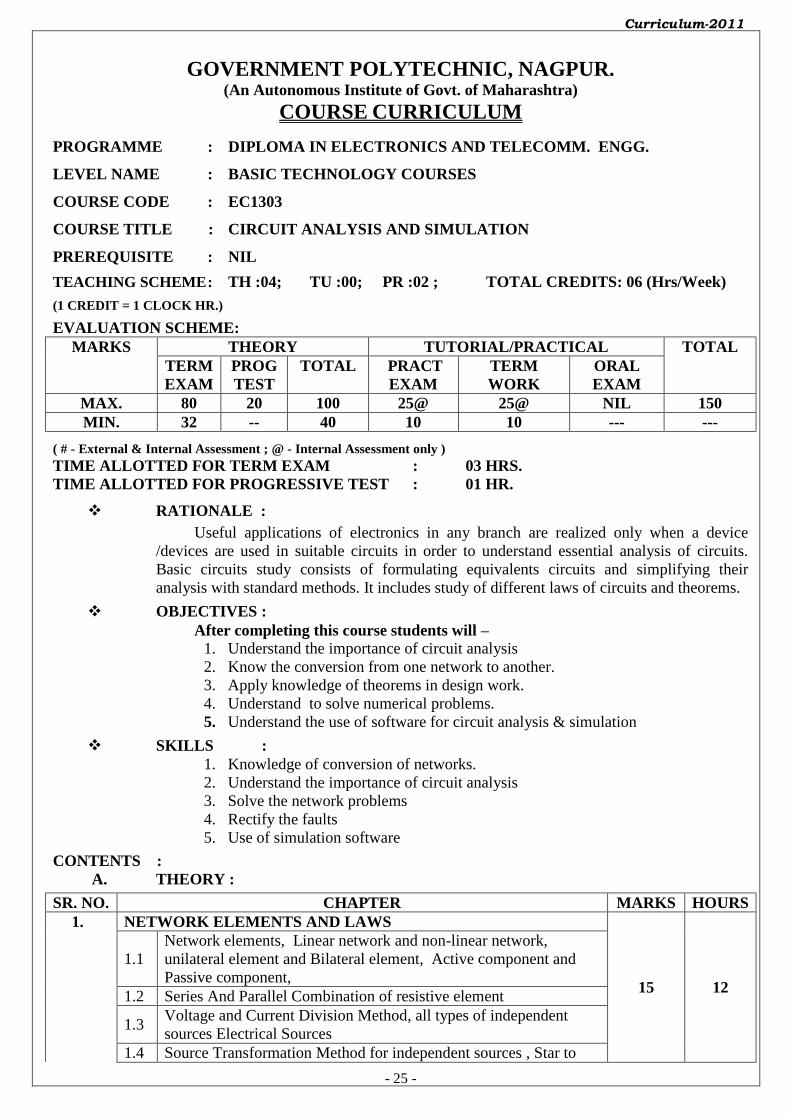
PROGRAMME : DIPLOMA IN ELECTRONICS AND TELECOMM. ENGG.
LEVEL NAME : BASIC TECHNOLOGY COURSES
COURSE CODE : EC1303
COURSE TITLE : CIRCUIT ANALYSIS AND SIMULATION
PREREQUISITE : NIL
TEACHING SCHEME : TH :04; TU :00; PR :02 ; TOTAL CREDITS: 06 (Hrs/Week)
(1 CREDIT = 1 CLOCK HR.)
EVALUATION SCHEME: MARKS THEORY TUTORIAL/PRACTICAL TOTAL
TERM
EXAM
PROG
TEST
TOTAL PRACT
EXAM
TERM
WORK
ORAL
EXAM
MAX. 80 20 100 25@ 25@ NIL 150
MIN. 32 -- 40 10 10 --- ---
( # - External & Internal Assessment ; @ - Internal Assessment only ) TIME ALLOTTED FOR TERM EXAM : 03 HRS. TIME ALLOTTED FOR PROGRESSIVE TEST : 01 HR.
RATIONALE :
Useful applications of electronics in any branch are realized only when a device
/devices are used in suitable circuits in order to understand essential analysis of circuits.
Basic circuits study consists of formulating equivalents circuits and simplifying their
analysis with standard methods. It includes study of different laws of circuits and theorems.
OBJECTIVES :
After completing this course students will –
1. Understand the importance of circuit analysis
2. Know the conversion from one network to another.
3. Apply knowledge of theorems in design work.
4. Understand to solve numerical problems.
5. Understand the use of software for circuit analysis & simulation
SKILLS :
1. Knowledge of conversion of networks.
2. Understand the importance of circuit analysis
3. Solve the network problems
4. Rectify the faults
5. Use of simulation software
CONTENTS :
A. THEORY :
SR. NO. CHAPTER MARKS HOURS
1. NETWORK ELEMENTS AND LAWS
15 12
1.1
Network elements, Linear network and non-linear network,
unilateral element and Bilateral element, Active component and
Passive component,
1.2 Series And Parallel Combination of resistive element
1.3 Voltage and Current Division Method, all types of independent
sources Electrical Sources
1.4 Source Transformation Method for independent sources , Star to

Curriculum-2011
- 26 -
Delta and Delta to Star Transformation
1.5 Principle of Duality
1.6 Kirchhoff’s Current and Voltage Law
2. MESH AND NODAL ANALYSIS
10 08
2.1 Mesh Analysis
2.2 Concept of Super Mesh
2.3 Nodal Analysis
2.4 Concept of Super Node
3. NETWORK THEOREMS
15 08
3.1 Superposition Theorem
3.2 Thevenin’s Theorem
3.3 Norton’s Theorem
3.4 Maximum Power Transfer Theorem
3.5 Reciprocity theorem
4. RESONANT CIRCUITS
10 08
4.1 Definition of Resonance and types of resonance
4.2 Series Resonance, Series Resonant circuit
4.3 Impedance and Phase angle of Series resonant circuit
4.4 Voltage and Current in series resonant circuit
4.5 The Quality Factor and Bandwidth
4.6 Parallel Resonance
4.7 Resonant Frequency for a Tank Circuit, Variation of impedance
with Frequency
4.8 Q Factor and Bandwidth of a parallel resonance
5. TYPES OF SIGNALS AND TRANSIENT RESPONSES
08 06
5.1 Sinusoidal(AC), Step (DC), Ramp, Exponential, Square signals
5.2 Charging and Discharging of Capacitor , Time constant
5.3 RC circuits: Integrator and Differentiator
5.3 Response of RC circuits to sinusoidal, step, ramp, exponential
signal s
6. FILTER NETWORKS
08 08
6.1 Classification of Filters , T-Networks & π-Networks, Ladder
Networks
6.2 Low pass Filter
6.3 High Pass Filter
6.4 Band Pass filter
6.5 Band Stop Filter
6.6 Constant-K filters (all types)
7. TWO PORT NETWORKS
08 08
7.1 Two Port Network
7.2 Open Circuit Impedance(Z) parameters
7.3 Short circuit Admittance(Y) parameter
7.4 Transmission(ABCD) parameters
7.5 Hybrid(h) parameters
8. NETWORK ANALYSIS WITH PSPICE
06 06
8.1 Introduction, Commands of PSpice and their syntax, Execution
steps
8.2 Resistive circuits with Independent voltage and current sources
8.3 Transient response of RLC circuit
8.6 Frequency response of RLC circuit
Total 80 64
Curriculum-2011
- 27 -
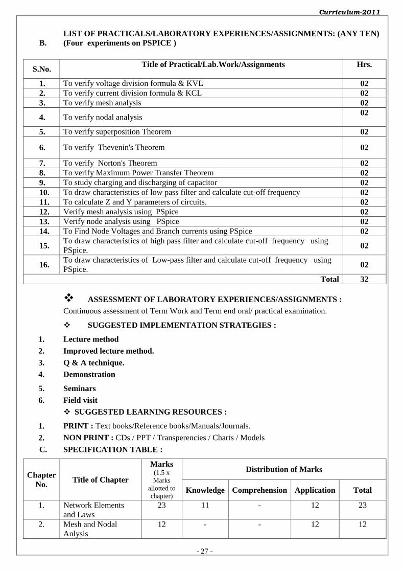
B.
LIST OF PRACTICALS/LABORATORY EXPERIENCES/ASSIGNMENTS: (ANY TEN)
(Four experiments on PSPICE )
S.No. Title of Practical/Lab.Work/Assignments
Hrs.
1. To verify voltage division formula & KVL 02
2. To verify current division formula & KCL 02
3. To verify mesh analysis 02
4. To verify nodal analysis 02
5. To verify superposition Theorem 02
6. To verify Thevenin's Theorem 02
7. To verify Norton's Theorem 02
8. To verify Maximum Power Transfer Theorem 02
9. To study charging and discharging of capacitor 02
10. To draw characteristics of low pass filter and calculate cut-off frequency 02
11. To calculate Z and Y parameters of circuits. 02
12. Verify mesh analysis using PSpice 02
13. Verify node analysis using PSpice 02
14. To Find Node Voltages and Branch currents using PSpice 02
15. To draw characteristics of high pass filter and calculate cut-off frequency using
PSpice. 02
16. To draw characteristics of Low-pass filter and calculate cut-off frequency using
PSpice. 02
Total 32
ASSESSMENT OF LABORATORY EXPERIENCES/ASSIGNMENTS :
Continuous assessment of Term Work and Term end oral/ practical examination.
SUGGESTED IMPLEMENTATION STRATEGIES :
1. Lecture method
2. Improved lecture method.
3. Q & A technique.
4. Demonstration
5. Seminars
6. Field visit
SUGGESTED LEARNING RESOURCES :
1. PRINT : Text books/Reference books/Manuals/Journals.
2. NON PRINT : CDs / PPT / Transperencies / Charts / Models
C. SPECIFICATION TABLE :
Chapter
No. Title of Chapter
Marks (1.5 x
Marks
allotted to
chapter)
Distribution of Marks
Knowledge Comprehension Application Total
1. Network Elements
and Laws
23 11 - 12 23
2. Mesh and Nodal
Anlysis
12 - - 12 12

Curriculum-2011
- 28 -
3. Network Theorems 18 06 12 18
4. Resonant Circuits 15 03 06 06 15
5. Types of Signals and
transient Responses
09 03 03 03 09
6. Electric filter 09 03 03 03 09
7. Two Port Network 12 06 -- 06 12
8. Network Analysis
with PSpice
22 06 06 10 22
Total 120 38 18 64 120
D. REFERENCE & TEXT BOOKS:
S.N. Title Author, Publisher, Edition
and Year Of publication ISBN Number
1.
Circuits and Networks, Analysis
and Synthesis
A Sudhakar & Shyammohan S
Palli,Taha McGraw-Hill,
Second Edition,2006
0-07-048295-0
2.
Fundamentals of Electrical
Networks
B. R. Gupta & Vandana
Singhal, S Chand & company
ltd,2005
81-219-2318-2
3. Theory and Problems in Circuit
Ananlysis
T S K V Iyer, TMH,1995 0-07-462165-3
4. Fundamentals of Electric Circuit
Theory
D Chattopadhya & P. C.
Rakshit, S. Chand,1991
81-219-0008-5
5.
Network Analysis M. e. Van Valkenburg,
Prentice Hall of India, Third
Edition,1997
81-203-0156-0
E. LIST OF EXPERTS & TEACHERS WHO CONTRIBUTED FOR THIS CURRICULUM:
S.N. Name Designation Institute / Industry
1. Mrs. Ujwala Potdar Lecturer Govt.Poly.Nagpur
2. Mr. J. S. Ratale Lecturer Govt.Poly.Nagpur
-------------------------- ------------------------
(Member Secretary PBOS) (Chairman PBOS)
Curriculum-2011
- 29 -
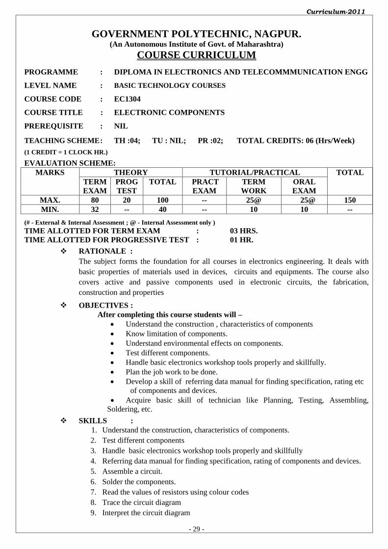
GOVERNMENT POLYTECHNIC, NAGPUR. (An Autonomous Institute of Govt. of Maharashtra)
COURSE CURRICULUM
PROGRAMME : DIPLOMA IN ELECTRONICS AND TELECOMMMUNICATION ENGG
LEVEL NAME : BASIC TECHNOLOGY COURSES
COURSE CODE : EC1304
COURSE TITLE : ELECTRONIC COMPONENTS
PREREQUISITE : NIL
TEACHING SCHEME : TH :04; TU : NIL; PR :02; TOTAL CREDITS: 06 (Hrs/Week)
(1 CREDIT = 1 CLOCK HR.)
EVALUATION SCHEME: MARKS THEORY TUTORIAL/PRACTICAL TOTAL
TERM
EXAM
PROG
TEST
TOTAL PRACT
EXAM
TERM
WORK
ORAL
EXAM
MAX. 80 20 100 -- 25@ 25@ 150
MIN. 32 -- 40 -- 10 10 --
(# - External & Internal Assessment ; @ - Internal Assessment only ) TIME ALLOTTED FOR TERM EXAM : 03 HRS. TIME ALLOTTED FOR PROGRESSIVE TEST : 01 HR.
RATIONALE :
The subject forms the foundation for all courses in electronics engineering. It deals with
basic properties of materials used in devices, circuits and equipments. The course also
covers active and passive components used in electronic circuits, the fabrication,
construction and properties
OBJECTIVES :
After completing this course students will –
Understand the construction , characteristics of components
Know limitation of components.
Understand environmental effects on components.
Test different components.
Handle basic electronics workshop tools properly and skillfully.
Plan the job work to be done.
Develop a skill of referring data manual for finding specification, rating etc
of components and devices.
Acquire basic skill of technician like Planning, Testing, Assembling,
Soldering, etc.
SKILLS :
1. Understand the construction, characteristics of components.
2. Test different components
3. Handle basic electronics workshop tools properly and skillfully
4. Referring data manual for finding specification, rating of components and devices.
5. Assemble a circuit.
6. Solder the components.
7. Read the values of resistors using colour codes
8. Trace the circuit diagram
9. Interpret the circuit diagram
Curriculum-2011
- 30 -
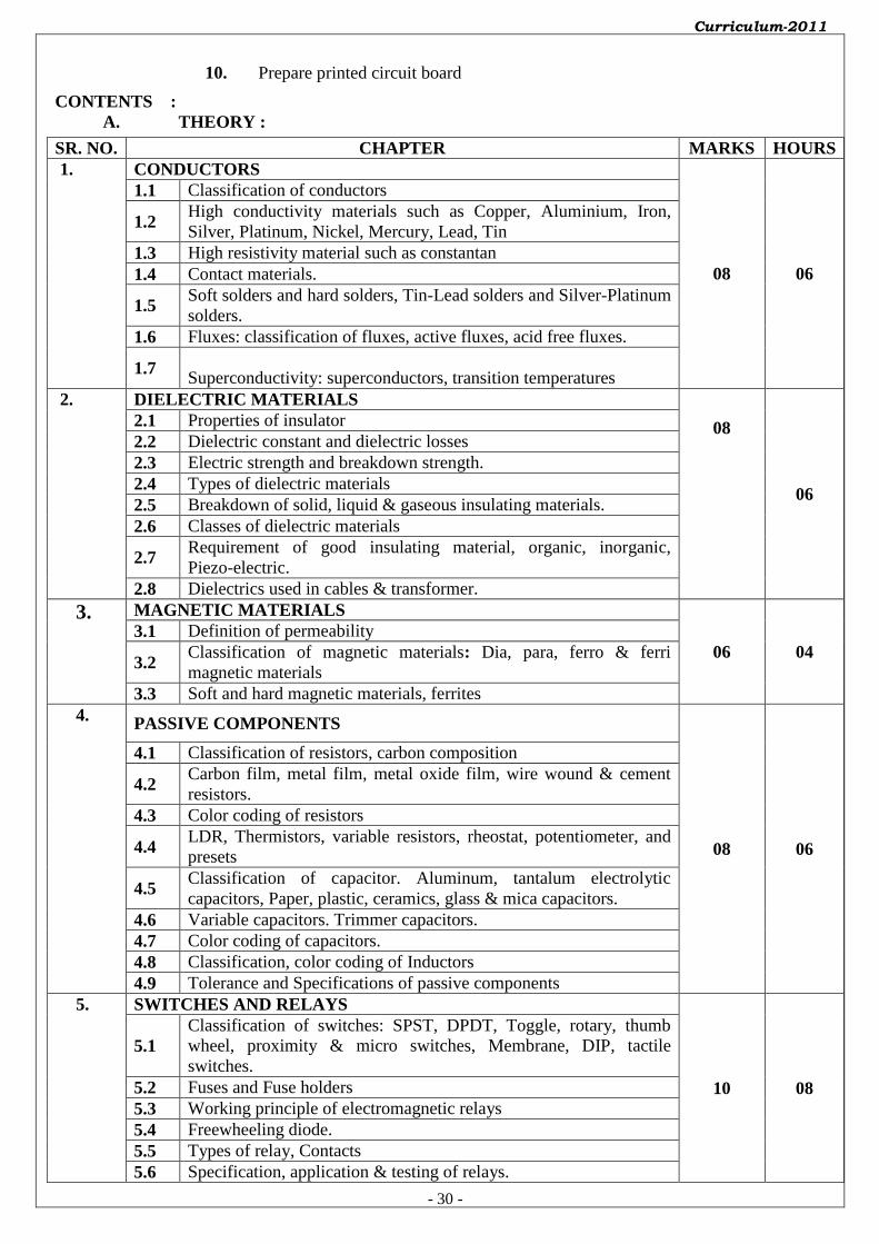
10. Prepare printed circuit board
CONTENTS :
A. THEORY :
SR. NO. CHAPTER MARKS HOURS
1. CONDUCTORS
08 06
1.1 Classification of conductors
1.2 High conductivity materials such as Copper, Aluminium, Iron,
Silver, Platinum, Nickel, Mercury, Lead, Tin
1.3 High resistivity material such as constantan
1.4 Contact materials.
1.5 Soft solders and hard solders, Tin-Lead solders and Silver-Platinum
solders.
1.6 Fluxes: classification of fluxes, active fluxes, acid free fluxes.
1.7 Superconductivity: superconductors, transition temperatures
2. DIELECTRIC MATERIALS
08
06
2.1 Properties of insulator
2.2 Dielectric constant and dielectric losses
2.3 Electric strength and breakdown strength.
2.4 Types of dielectric materials
2.5 Breakdown of solid, liquid & gaseous insulating materials.
2.6 Classes of dielectric materials
2.7 Requirement of good insulating material, organic, inorganic,
Piezo-electric.
2.8 Dielectrics used in cables & transformer.
3. MAGNETIC MATERIALS
06 04
3.1 Definition of permeability
3.2 Classification of magnetic materials: Dia, para, ferro & ferri
magnetic materials
3.3 Soft and hard magnetic materials, ferrites
4. PASSIVE COMPONENTS
08 06
4.1 Classification of resistors, carbon composition
4.2 Carbon film, metal film, metal oxide film, wire wound & cement
resistors.
4.3 Color coding of resistors
4.4 LDR, Thermistors, variable resistors, rheostat, potentiometer, and
presets
4.5 Classification of capacitor. Aluminum, tantalum electrolytic
capacitors, Paper, plastic, ceramics, glass & mica capacitors.
4.6 Variable capacitors. Trimmer capacitors.
4.7 Color coding of capacitors.
4.8 Classification, color coding of Inductors
4.9 Tolerance and Specifications of passive components
5. SWITCHES AND RELAYS
10 08
5.1
Classification of switches: SPST, DPDT, Toggle, rotary, thumb
wheel, proximity & micro switches, Membrane, DIP, tactile
switches.
5.2 Fuses and Fuse holders
5.3 Working principle of electromagnetic relays
5.4 Freewheeling diode.
5.5 Types of relay, Contacts
5.6 Specification, application & testing of relays.

Curriculum-2011
- 31 -
6. CABLES AND CONNECTORS
10 08
6.1 Materials for wire, Types of wires, Use of wire.
6.2 Factors of selection of insulating materials, Insulating sleeves
6.3 Cables: Types of cables, Coaxial & twin cables.
6.4 Twisted & shielded pair cables, R.F. cables
6.5 Types of sheathed cables.
6.6 Optical fiber cable.
6.7 Characteristics of impedance cable.
6.8 Choice for size of cables, Identification of wire by colours
6.9 Types of connectors, Audio, R.F., VHF, BNC TNC & PCB edge
connectors Jacks, sockets & circular connectors
7. DISPLAYS
10 10
7.1 Types displays
7.2 LED and LCD displays
7.3 Advantages, disadvantages, Applications of displays
7.4 Sources of light, surface mount LED, Color LCD
7.5 Fluorescent displays, Electrophoretic image display, liquid vapour
display
7.6 Segmental and Dot matrix displays
7.7 Advantages, disadvantages, Applications of displays
8. MICROPHONES AND SPEAKERS
08 06
8.1 General requirements and classifications of microphones
8.2 Carbon, crystal, condenser, and ribbon microphones.
8.3 Loudspeakers: baffles and enclosures, types of loudspeakers,
8.4 Crossover masterworks of loudspeakers.
8.5 Horn loudspeakers, Exponential and column loudspeakers
9. ACTIVE COMPONENTS
06 06
9.1 Specification & Types of packages of diodes, transistor, JFET, and
MOSFET
9.2 IC packages- DIP , PLCC , BGA ,PPFF etc
9.3 Identification of ICs & Components.
9.4 Heat-sink requirement
10. PHOTOSENSITIVE DEVICES
06 04 10.1 Construction and operating principle
10.2 Specifications of light dependent resistor(LDR), Photo diode,
phototransistors and light emitting diode (LED)
Total 80 64
B. LIST OF PRACTICALS/LABORATORY EXPERIENCES/ASSIGNMENTS: (Any ten)
S.No. Title of Practical/Lab.Work/Assignments(ANY TEN) Hrs.
1. To draw symbols for components used in electronic circuits. 02
2. To study different types of resistors 02
3. To study different types of capacitors 02
4. To study different types of active components 02
5. To test different diodes 02
6. To test different transistors 02
7. To study various switches 02
8. To study different relays 02
9. To study displays (7-segment LCD and LED) 02
10. To study different connectors (BNC, PCBs, D, FRC, ZIF) 04
11. To study microphone 02
12. To study various speakers 04
13. Study of different semiconductor component packages 04
Curriculum-2011
- 32 -
Total 32
ASSESSMENT OF LABORATORY EXPERIENCES/ASSIGNMENTS :
Continuous assessment of Term Work and Term end oral/ practical examination.
SUGGESTED IMPLEMENTATION STRATEGIES :
1. Lecture method
2. Improved lecture method.
3. Q & A technique.
4. Demonstration
5. Field visit
SUGGESTED LEARNING RESOURCES :
1. PRINT : Text books/Reference books/Manuals/Journals.
2. NON PRINT : CDs / PPT / Transparences / Charts / Models
C. SPECIFICATION TABLE :
Chapter
No. Title of Chapter
Marks (1.5 x
Marks
allotted to
chapter)
Distribution of Marks
Knowledge Comprehension Application Total
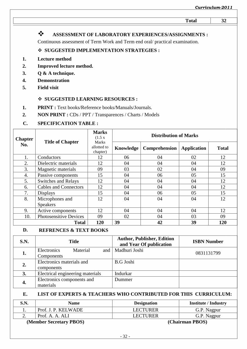
1. Conductors 12 06 04 02 12
2. Dielectric materials 12 04 04 04 12
3. Magnetic materials 09 03 02 04 09
4. Passive components 15 04 06 05 15
5. Switches and Relays 12 04 04 04 12
6. Cables and Connectors 12 04 04 04 12
7. Displays 15 04 06 05 15
8. Microphones and
Speakers
12 04 04 04 12
9. Active components 12 04 04 04 12
10. Photosensitive Devices 09 02 04 03 09
Total 120 39 42 39 120
D. REFRENCES & TEXT BOOKS
S.N. Title Author, Publisher, Edition
and Year Of publication ISBN Number
1. Electronics Material and
Components
Madhuri Joshi
0831131799
2. Electronics materials and
components
B.G Joshi
3. Electrical engineering materials Indurkar
4. Electronics components and
materials
Dummer
E. LIST OF EXPERTS & TEACHERS WHO CONTRIBUTED FOR THIS CURRICULUM:
S.N. Name Designation Institute / Industry
1. Prof. J. P. KELWADE LECTURER G.P. Nagpur
2. Prof. A. A. ALI LECTURER G.P. Nagpur
(Member Secretary PBOS) (Chairman PBOS)
Curriculum-2011
- 33 -
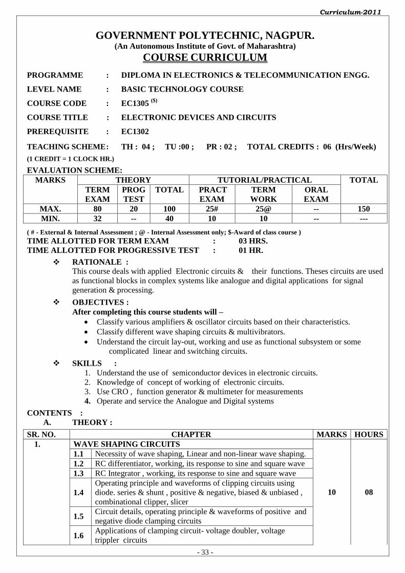
GOVERNMENT POLYTECHNIC, NAGPUR. (An Autonomous Institute of Govt. of Maharashtra)
COURSE CURRICULUM
PROGRAMME : DIPLOMA IN ELECTRONICS & TELECOMMUNICATION ENGG.
LEVEL NAME : BASIC TECHNOLOGY COURSE
COURSE CODE : EC1305 ($)
COURSE TITLE : ELECTRONIC DEVICES AND CIRCUITS
PREREQUISITE : EC1302
TEACHING SCHEME : TH : 04 ; TU :00 ; PR : 02 ; TOTAL CREDITS : 06 (Hrs/Week)
(1 CREDIT = 1 CLOCK HR.)
EVALUATION SCHEME: MARKS THEORY TUTORIAL/PRACTICAL TOTAL
TERM
EXAM
PROG
TEST
TOTAL PRACT
EXAM
TERM
WORK
ORAL
EXAM
MAX. 80 20 100 25# 25@ -- 150
MIN. 32 -- 40 10 10 -- ---
( # - External & Internal Assessment ; @ - Internal Assessment only; $-Award of class course ) TIME ALLOTTED FOR TERM EXAM : 03 HRS. TIME ALLOTTED FOR PROGRESSIVE TEST : 01 HR.
RATIONALE :
This course deals with applied Electronic circuits & their functions. Theses circuits are used
as functional blocks in complex systems like analogue and digital applications for signal
generation & processing.
OBJECTIVES :
After completing this course students will –
Classify various amplifiers & oscillator circuits based on their characteristics.
Classify different wave shaping circuits & multivibrators.
Understand the circuit lay-out, working and use as functional subsystem or some
complicated linear and switching circuits.
SKILLS :
1. Understand the use of semiconductor devices in electronic circuits.
2. Knowledge of concept of working of electronic circuits.
3. Use CRO , function generator & multimeter for measurements
4. Operate and service the Analogue and Digital systems
CONTENTS :
A. THEORY :
SR. NO. CHAPTER MARKS HOURS
1. WAVE SHAPING CIRCUITS
10 08
1.1 Necessity of wave shaping, Linear and non-linear wave shaping.
1.2 RC differentiator, working, its response to sine and square wave
1.3 RC Integrator , working, its response to sine and square wave
1.4
Operating principle and waveforms of clipping circuits using
diode. series & shunt , positive & negative, biased & unbiased ,
combinational clipper, slicer
1.5 Circuit details, operating principle & waveforms of positive and
negative diode clamping circuits
1.6 Applications of clamping circuit- voltage doubler, voltage
trippler circuits

Curriculum-2011
- 34 -
2. BJT AMPLIFIER
12 08
2.1 Multistage amplifiers. Need of Multistage Amplifiers, Gain of
amplifier.
2.2
Circuit diagram, operating principle, frequency response,
advantages, disadvantages and applications of two stage
resistance-capacitance (RC) coupled amplifiers.
2.3
Circuit diagram, operating principle, frequency response,
advantages, disadvantages and applications of two stage
impedance-coupled (LC) amplifiers.
2.4
Circuit diagram, operating principle, frequency response,
advantages, disadvantages and applications of two stage,
transformer- coupled (TC) amplifiers.
2.5
Circuit diagram, operating principle, frequency response,
advantages, disadvantages and applications of two stage direct-
coupled (DC) amplifiers.
2.6 Comparison of RC , LC , TC and DC couplings.
2.7 Hybrid (h) parameters
2.8 Meaning of h-parameters of single stage CE amplifier.
3. AUDIO POWER AMPLIFIER
10 08
3.1 Comparison of voltage and power amplifiers.
3.2 Definitions of collector efficiency, distortion and power
dissipation capability.
3.3
Circuit diagram, operating principle, characteristic features,
advantages, disadvantages and applications of class A, B, AB
amplifiers.
3.4
Circuit diagram, operating principle, characteristic features,
advantages, disadvantages and applications Class B push-pull
amplifier
3.5 Comparison of class A & B amplifiers.
3.6 Complementary symmetry power amplifiers.
3.7 Thermal runway and heat sinks (No mathematical analysis)
4. TUNED VOLTAGE AMPLIFIERS
08 06
4.1 Necessity of tuned amplifier.
4.2 Basic tuned circuits, series & parallel resonance in tuned
circuits.
4.3 Resonant frequency, resonance curve, band width and selectivity
of parallel resonant circuit..
4.4 Circuit diagram , working & frequency response of single tuned
circuits
4.5 Circuit diagram , working & frequency response of double tuned
circuits
4.6 Circuit diagram , working & frequency response of stagger tuned
circuits
4.7 Advantages and disadvantages of tuned voltage amplifiers.
5. FEEDBACK AMPLIFIERS
08 06
5.1 Block diagram and principle of feedback. Types of feedback.
5.2 Types of negative feedback connections – voltage shunt, voltage
series, current shunt & current series. Their comparison.
5.3 Advantages, disadvantages of positive and negative feedback in
amplifiers.
5.4 Effect of Negative feedback
Curriculum-2011
- 35 -
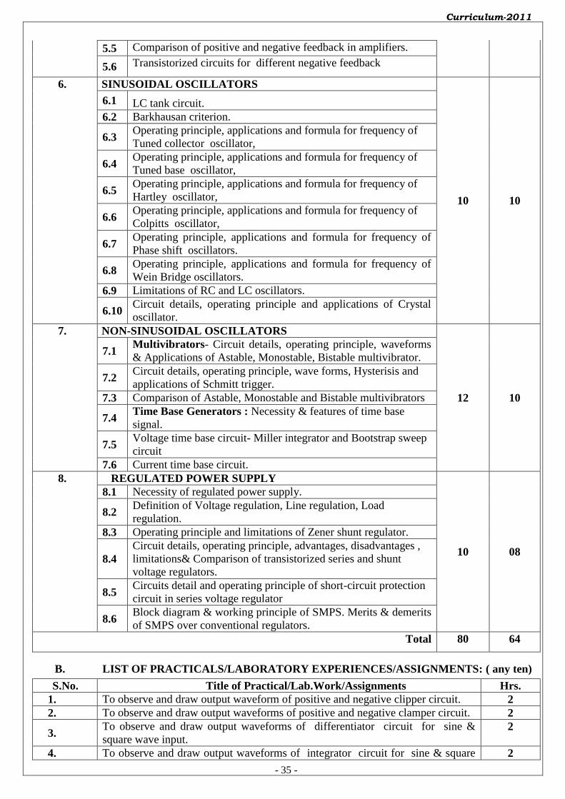
5.5 Comparison of positive and negative feedback in amplifiers.
5.6 Transistorized circuits for different negative feedback
6. SINUSOIDAL OSCILLATORS
10 10
6.1 LC tank circuit.
6.2 Barkhausan criterion.
6.3 Operating principle, applications and formula for frequency of
Tuned collector oscillator,
6.4 Operating principle, applications and formula for frequency of
Tuned base oscillator,
6.5 Operating principle, applications and formula for frequency of
Hartley oscillator,
6.6 Operating principle, applications and formula for frequency of
Colpitts oscillator,
6.7 Operating principle, applications and formula for frequency of
Phase shift oscillators.
6.8 Operating principle, applications and formula for frequency of
Wein Bridge oscillators.
6.9 Limitations of RC and LC oscillators.
6.10 Circuit details, operating principle and applications of Crystal
oscillator.
7. NON-SINUSOIDAL OSCILLATORS
12 10
7.1 Multivibrators- Circuit details, operating principle, waveforms
& Applications of Astable, Monostable, Bistable multivibrator.
7.2 Circuit details, operating principle, wave forms, Hysterisis and
applications of Schmitt trigger.
7.3 Comparison of Astable, Monostable and Bistable multivibrators
7.4 Time Base Generators : Necessity & features of time base
signal.
7.5 Voltage time base circuit- Miller integrator and Bootstrap sweep
circuit
7.6 Current time base circuit.
8. REGULATED POWER SUPPLY
10 08
8.1 Necessity of regulated power supply.
8.2 Definition of Voltage regulation, Line regulation, Load
regulation.
8.3 Operating principle and limitations of Zener shunt regulator.
8.4
Circuit details, operating principle, advantages, disadvantages ,
limitations& Comparison of transistorized series and shunt
voltage regulators.
8.5 Circuits detail and operating principle of short-circuit protection
circuit in series voltage regulator
8.6 Block diagram & working principle of SMPS. Merits & demerits
of SMPS over conventional regulators.
Total 80 64
B. LIST OF PRACTICALS/LABORATORY EXPERIENCES/ASSIGNMENTS: ( any ten)
S.No. Title of Practical/Lab.Work/Assignments Hrs.
1. To observe and draw output waveform of positive and negative clipper circuit. 2
2. To observe and draw output waveforms of positive and negative clamper circuit. 2
3. To observe and draw output waveforms of differentiator circuit for sine &
square wave input. 2
4. To observe and draw output waveforms of integrator circuit for sine & square 2
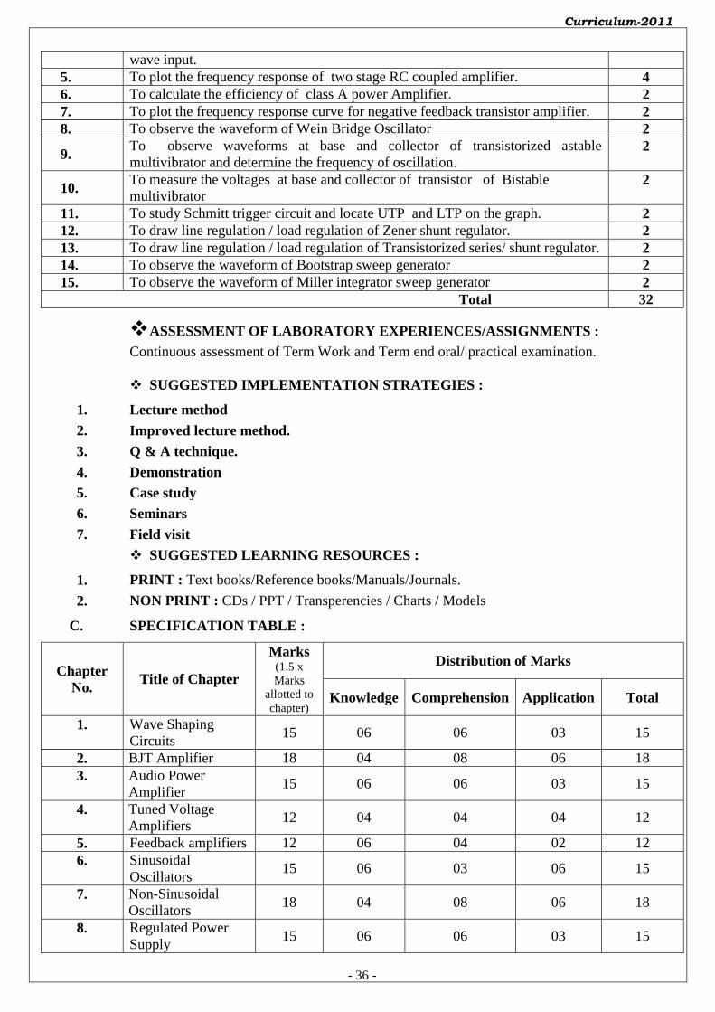
Curriculum-2011
- 36 -
wave input.
5. To plot the frequency response of two stage RC coupled amplifier. 4
6. To calculate the efficiency of class A power Amplifier. 2
7. To plot the frequency response curve for negative feedback transistor amplifier. 2
8. To observe the waveform of Wein Bridge Oscillator 2
9. To observe waveforms at base and collector of transistorized astable
multivibrator and determine the frequency of oscillation. 2
10. To measure the voltages at base and collector of transistor of Bistable
multivibrator 2
11. To study Schmitt trigger circuit and locate UTP and LTP on the graph. 2
12. To draw line regulation / load regulation of Zener shunt regulator. 2
13. To draw line regulation / load regulation of Transistorized series/ shunt regulator. 2
14. To observe the waveform of Bootstrap sweep generator 2
15. To observe the waveform of Miller integrator sweep generator 2
Total 32
ASSESSMENT OF LABORATORY EXPERIENCES/ASSIGNMENTS :
Continuous assessment of Term Work and Term end oral/ practical examination.
SUGGESTED IMPLEMENTATION STRATEGIES :
1. Lecture method
2. Improved lecture method.
3. Q & A technique.
4. Demonstration
5. Case study
6. Seminars
7. Field visit
SUGGESTED LEARNING RESOURCES :
1. PRINT : Text books/Reference books/Manuals/Journals.
2. NON PRINT : CDs / PPT / Transperencies / Charts / Models
C. SPECIFICATION TABLE :
Chapter
No. Title of Chapter
Marks (1.5 x
Marks
allotted to
chapter)
Distribution of Marks
Knowledge Comprehension Application Total
1. Wave Shaping
Circuits 15 06 06 03 15
2. BJT Amplifier 18 04 08 06 18
3. Audio Power
Amplifier 15 06 06 03 15
4. Tuned Voltage
Amplifiers 12 04 04 04 12
5. Feedback amplifiers 12 06 04 02 12
6. Sinusoidal
Oscillators 15 06 03 06 15
7. Non-Sinusoidal
Oscillators 18 04 08 06 18
8. Regulated Power
Supply 15 06 06 03 15

Curriculum-2011
- 37 -
Total 120 42 45 33 120
D. REFERENCE & TEXT BOOKS:
S.N. Title Author, Publisher, Edition
and Year Of publication ISBN Number
1. Applied Electronics S. L. Sedha , S. Chand 9788121927833
2. Electronic device and circuits B. L. Theraja , S. Chand 8121921996
3. Electronics Devices & Circuits Allan Mottershed , Tata
McGraw Hill 9788120301245
4. Electronics Devices & Circuits S.Salivahanan , Tata McGraw
Hill 9780070084742
5. Integrated Electronics Millman Halkias , Tata
McGraw Hill 97881843120775
E. LIST OF EXPERTS & TEACHERS WHO CONTRIBUTED FOR THIS
CURRICULUM: S.N. Name Designation Institute / Industry
1. Mrs. M. N. Bawane Lecturer Govt.Poly.Nagpur
2. Mr. A. A. Ali Lecturer Govt.Poly.Nagpur
-------------------------- ------------------------
(Member Secretary PBOS) (Chairman PBOS)
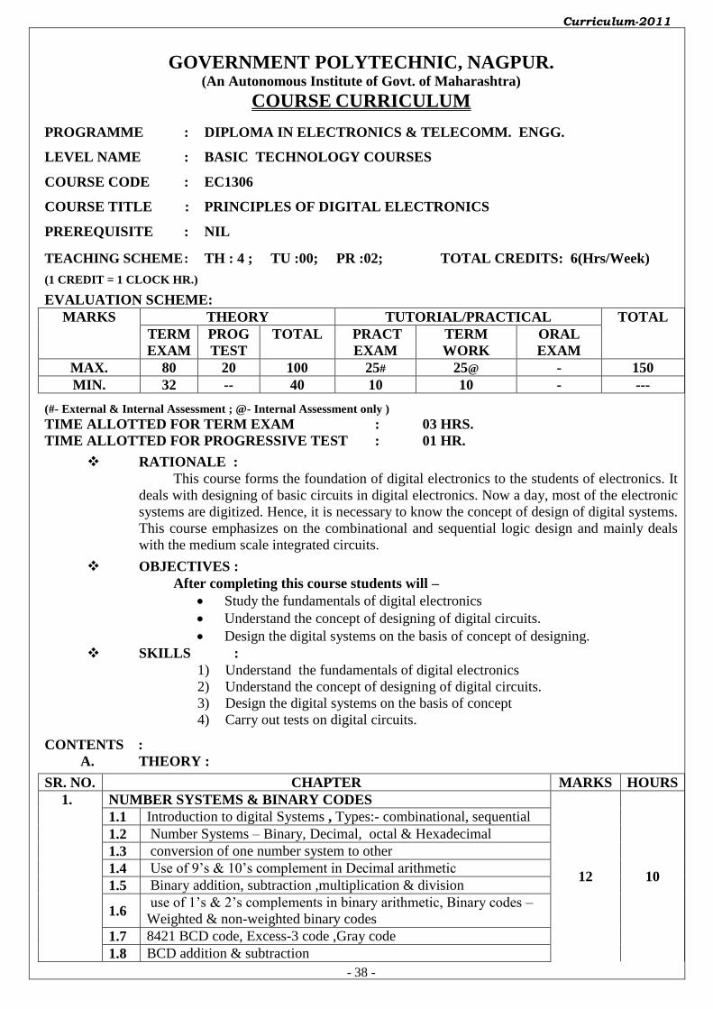
Curriculum-2011
- 38 -
GOVERNMENT POLYTECHNIC, NAGPUR. (An Autonomous Institute of Govt. of Maharashtra)
COURSE CURRICULUM
PROGRAMME : DIPLOMA IN ELECTRONICS & TELECOMM. ENGG.
LEVEL NAME : BASIC TECHNOLOGY COURSES
COURSE CODE : EC1306
COURSE TITLE : PRINCIPLES OF DIGITAL ELECTRONICS
PREREQUISITE : NIL
TEACHING SCHEME : TH : 4 ; TU :00; PR :02; TOTAL CREDITS: 6(Hrs/Week)
(1 CREDIT = 1 CLOCK HR.)
EVALUATION SCHEME: MARKS THEORY TUTORIAL/PRACTICAL TOTAL
TERM
EXAM
PROG
TEST
TOTAL PRACT
EXAM
TERM
WORK
ORAL
EXAM
MAX. 80 20 100 25# 25@ - 150
MIN. 32 -- 40 10 10 - ---
(#- External & Internal Assessment ; @- Internal Assessment only ) TIME ALLOTTED FOR TERM EXAM : 03 HRS. TIME ALLOTTED FOR PROGRESSIVE TEST : 01 HR.
RATIONALE :
This course forms the foundation of digital electronics to the students of electronics. It
deals with designing of basic circuits in digital electronics. Now a day, most of the electronic
systems are digitized. Hence, it is necessary to know the concept of design of digital systems.
This course emphasizes on the combinational and sequential logic design and mainly deals
with the medium scale integrated circuits.
OBJECTIVES :
After completing this course students will –
Study the fundamentals of digital electronics
Understand the concept of designing of digital circuits.
Design the digital systems on the basis of concept of designing.
SKILLS :
1) Understand the fundamentals of digital electronics
2) Understand the concept of designing of digital circuits.
3) Design the digital systems on the basis of concept
4) Carry out tests on digital circuits.
CONTENTS :
A. THEORY :
SR. NO. CHAPTER MARKS HOURS
1. NUMBER SYSTEMS & BINARY CODES
12 10
1.1 Introduction to digital Systems , Types:- combinational, sequential
1.2 Number Systems – Binary, Decimal, octal & Hexadecimal
1.3 conversion of one number system to other
1.4 Use of 9’s & 10’s complement in Decimal arithmetic
1.5 Binary addition, subtraction ,multiplication & division
1.6 use of 1’s & 2’s complements in binary arithmetic, Binary codes –
Weighted & non-weighted binary codes
1.7 8421 BCD code, Excess-3 code ,Gray code
1.8 BCD addition & subtraction
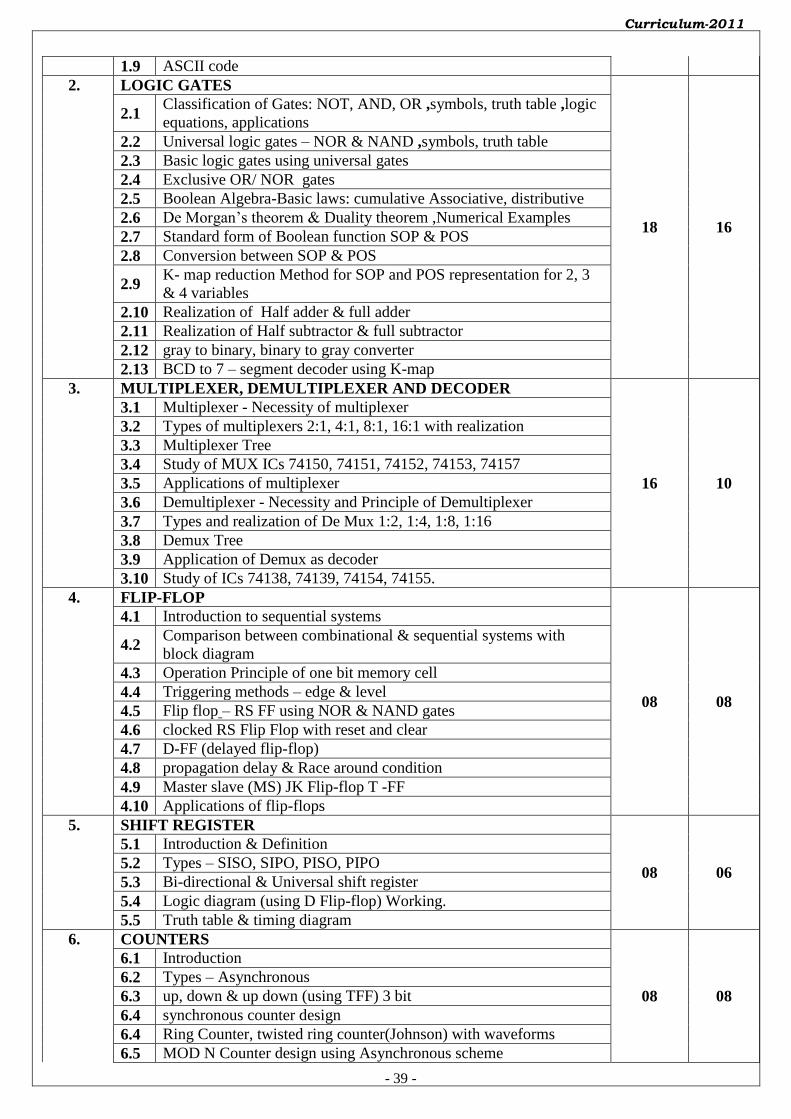
Curriculum-2011
- 39 -
1.9 ASCII code
2. LOGIC GATES
18 16
2.1 Classification of Gates: NOT, AND, OR ,symbols, truth table ,logic
equations, applications
2.2 Universal logic gates – NOR & NAND ,symbols, truth table
2.3 Basic logic gates using universal gates
2.4 Exclusive OR/ NOR gates
2.5 Boolean Algebra-Basic laws: cumulative Associative, distributive
2.6 De Morgan’s theorem & Duality theorem ,Numerical Examples
2.7 Standard form of Boolean function SOP & POS
2.8 Conversion between SOP & POS
2.9 K- map reduction Method for SOP and POS representation for 2, 3
& 4 variables
2.10 Realization of Half adder & full adder
2.11 Realization of Half subtractor & full subtractor
2.12 gray to binary, binary to gray converter
2.13 BCD to 7 – segment decoder using K-map
3. MULTIPLEXER, DEMULTIPLEXER AND DECODER
16 10
3.1 Multiplexer - Necessity of multiplexer
3.2 Types of multiplexers 2:1, 4:1, 8:1, 16:1 with realization
3.3 Multiplexer Tree
3.4 Study of MUX ICs 74150, 74151, 74152, 74153, 74157
3.5 Applications of multiplexer
3.6 Demultiplexer - Necessity and Principle of Demultiplexer
3.7 Types and realization of De Mux 1:2, 1:4, 1:8, 1:16
3.8 Demux Tree
3.9 Application of Demux as decoder
3.10 Study of ICs 74138, 74139, 74154, 74155.
4. FLIP-FLOP
08 08
4.1 Introduction to sequential systems
4.2 Comparison between combinational & sequential systems with
block diagram
4.3 Operation Principle of one bit memory cell
4.4 Triggering methods – edge & level
4.5 Flip flop – RS FF using NOR & NAND gates
4.6 clocked RS Flip Flop with reset and clear
4.7 D-FF (delayed flip-flop)
4.8 propagation delay & Race around condition
4.9 Master slave (MS) JK Flip-flop T -FF
4.10 Applications of flip-flops
5. SHIFT REGISTER
08 06
5.1 Introduction & Definition
5.2 Types – SISO, SIPO, PISO, PIPO
5.3 Bi-directional & Universal shift register
5.4 Logic diagram (using D Flip-flop) Working.
5.5 Truth table & timing diagram
6. COUNTERS
08 08
6.1 Introduction
6.2 Types – Asynchronous
6.3 up, down & up down (using TFF) 3 bit
6.4 synchronous counter design
6.4 Ring Counter, twisted ring counter(Johnson) with waveforms
6.5 MOD N Counter design using Asynchronous scheme
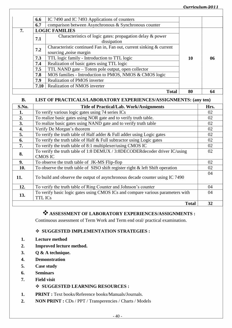
Curriculum-2011
- 40 -
6.6 IC 7490 and IC 7493 Applications of counters
6.7 comparison between Asynchronous & Synchronous counter
7. LOGIC FAMILIES
10 06
7.1 Characteristics of logic gates: propagation delay & power
dissipation
7.2 Characteristic continued Fan in, Fan out, current sinking & current
sourcing ,noise margin
7.3 TTL logic family - Introduction to TTL logic
7.4 Realization of basic gates using TTL logic
7.5 TTL NAND gate – Totem pole output, open collector
7.8 MOS families - Introduction to PMOS, NMOS & CMOS logic
7.9 Realization of PMOS inverter
7.10 Realization of NMOS inverter
Total 80 64
B. LIST OF PRACTICALS/LABORATORY EXPERIENCES/ASSIGNMENTS: (any ten)
S.No. Title of Practical/Lab. Work/Assignments Hrs.
1. To verify various logic gates using 74 series ICs 02
2. To realize basic gates using NOR gate and to verify truth table. 02
3. To realize basic gates using NAND gate and to verify truth table 02
4. Verify De Morgan’s theorem 02
5. To verify the truth table of Half adder & Full adder using Logic gates 02
6. To verify the truth table of Half & Full subtractor using Logic gates 02
7. To verify the truth table of 8:1 multiplexer/using CMOS IC 02
8. To verify the truth table of 1:8 DEMUX / 3:8DECODERdecoder driver IC/using
CMOS IC
02
9. To observe the truth table of JK-MS Flip-flop 02
10. To observe the truth table of SISO shift register right & left Shift operation 02
11. To build and observe the output of asynchronous decade counter using IC 7490 04
12. To verify the truth table of Ring Counter and Johnson’s counter 04
13. To verify basic logic gates using CMOS ICs and compare various parameters with
TTL ICs
04
Total 32
ASSESSMENT OF LABORATORY EXPERIENCES/ASSIGNMENTS :
Continuous assessment of Term Work and Term end oral/ practical examination.
SUGGESTED IMPLEMENTATION STRATEGIES :
1. Lecture method
2. Improved lecture method.
3. Q & A technique.
4. Demonstration
5. Case study
6. Seminars
7. Field visit
SUGGESTED LEARNING RESOURCES :
1. PRINT : Text books/Reference books/Manuals/Journals.
2. NON PRINT : CDs / PPT / Transperencies / Charts / Models

Curriculum-2011
- 41 -
C. SPECIFICATION TABLE :
Chapter
No. Title of Chapter
Marks (1.5 x Marks
allotted to
chapter)
Distribution of Marks
Knowledge Comprehension Application Total
1. Number Systems &
Binary Codes
18 08 10 00 18
2. Logic Gates 27 07 18 02 27
3. Multiplexer,
Demultiplexer and
Decoder
24 04 18 02 24
4. Flip-flop 12 02 08 02 12
5. Shift register 12 02 10 00 12
6. Counters 12 02 08 02 12
7. Logic Families 15 04 11 00 15
Total 120 29 83 08 120
D. REFERENCE & TEXT BOOKS:
S.N. Title Author, Publisher, Edition
and Year Of publication ISBN Number
1. Digital Electronics…. Tata McGraw-Hill R.P.Jain
9780070669116
2. Digital Principles & Applications
Malvino & Leach 9780070398375
3. Fundamentals of Digital Circuits A. Anand Kumar 9788120336797
4. Digital Electronics William Gothman 9788120303485
E. LIST OF EXPERTS & TEACHERS WHO CONTRIBUTED FOR THIS CURRICULUM:
S.N. Name Designation Institute / Industry
1. Prof. V.J.Dongre Lecturer(Sr.Scale) Govt. Polytechnic Nagpur
2. Prof D.B.Alaspure Lecturer Govt. Polytechnic Nagpur
3. Prof.J.P. Kelwade Lecturer Govt. Polytechnic Nagpur
-------------------------- ------------------------
(Member Secretary PBOS) (Chairman PBOS)
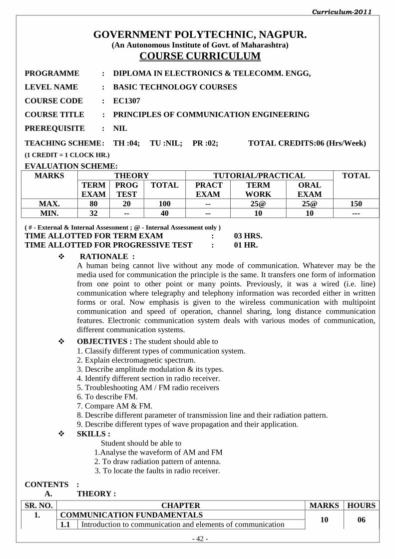
Curriculum-2011
- 42 -
GOVERNMENT POLYTECHNIC, NAGPUR. (An Autonomous Institute of Govt. of Maharashtra)
COURSE CURRICULUM
PROGRAMME : DIPLOMA IN ELECTRONICS & TELECOMM. ENGG,
LEVEL NAME : BASIC TECHNOLOGY COURSES
COURSE CODE : EC1307
COURSE TITLE : PRINCIPLES OF COMMUNICATION ENGINEERING
PREREQUISITE : NIL
TEACHING SCHEME : TH :04; TU :NIL; PR :02; TOTAL CREDITS:06 (Hrs/Week)
(1 CREDIT = 1 CLOCK HR.)
EVALUATION SCHEME: MARKS THEORY TUTORIAL/PRACTICAL TOTAL
TERM
EXAM
PROG
TEST
TOTAL PRACT
EXAM
TERM
WORK
ORAL
EXAM
MAX. 80 20 100 -- 25@ 25@ 150
MIN. 32 -- 40 -- 10 10 ---
( # - External & Internal Assessment ; @ - Internal Assessment only ) TIME ALLOTTED FOR TERM EXAM : 03 HRS. TIME ALLOTTED FOR PROGRESSIVE TEST : 01 HR.
RATIONALE : A human being cannot live without any mode of communication. Whatever may be the
media used for communication the principle is the same. It transfers one form of information
from one point to other point or many points. Previously, it was a wired (i.e. line)
communication where telegraphy and telephony information was recorded either in written
forms or oral. Now emphasis is given to the wireless communication with multipoint
communication and speed of operation, channel sharing, long distance communication
features. Electronic communication system deals with various modes of communication,
different communication systems.
OBJECTIVES : The student should able to
1. Classify different types of communication system.
2. Explain electromagnetic spectrum.
3. Describe amplitude modulation & its types.
4. Identify different section in radio receiver.
5. Troubleshooting AM / FM radio receivers
6. To describe FM.
7. Compare AM & FM.
8. Describe different parameter of transmission line and their radiation pattern.
9. Describe different types of wave propagation and their application.
SKILLS :
Student should be able to
1.Analyse the waveform of AM and FM
2. To draw radiation pattern of antenna.
3. To locate the faults in radio receiver.
CONTENTS :
A. THEORY :
SR. NO. CHAPTER MARKS HOURS
1. COMMUNICATION FUNDAMENTALS 10 06
1.1 Introduction to communication and elements of communication
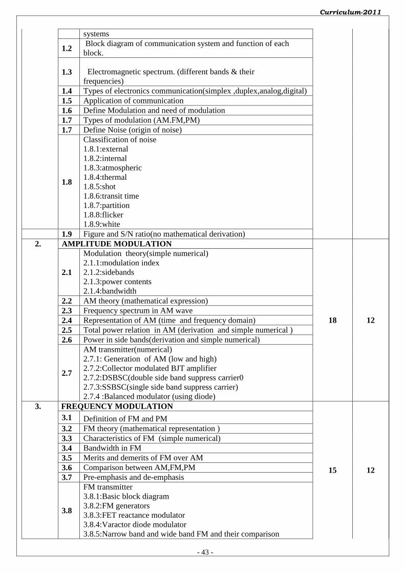
Curriculum-2011
- 43 -
systems
1.2 Block diagram of communication system and function of each
block.
1.3 Electromagnetic spectrum. (different bands & their
frequencies)
1.4 Types of electronics communication(simplex ,duplex,analog,digital)
1.5 Application of communication
1.6 Define Modulation and need of modulation
1.7 Types of modulation (AM.FM,PM)
1.7 Define Noise (origin of noise)
1.8
Classification of noise
1.8.1:external
1.8.2:internal
1.8.3:atmospheric
1.8.4:thermal
1.8.5:shot
1.8.6:transit time
1.8.7:partition
1.8.8:flicker
1.8.9:white
1.9 Figure and S/N ratio(no mathematical derivation)
2. AMPLITUDE MODULATION
18 12
2.1
Modulation theory(simple numerical)
2.1.1:modulation index
2.1.2:sidebands
2.1.3:power contents
2.1.4:bandwidth
2.2 AM theory (mathematical expression)
2.3 Frequency spectrum in AM wave
2.4 Representation of AM (time and frequency domain)
2.5 Total power relation in AM (derivation and simple numerical )
2.6 Power in side bands(derivation and simple numerical)
2.7
AM transmitter(numerical)
2.7.1: Generation of AM (low and high)
2.7.2:Collector modulated BJT amplifier
2.7.2:DSBSC(double side band suppress carrier0
2.7.3:SSBSC(single side band suppress carrier)
2.7.4 :Balanced modulator (using diode)
3. FREQUENCY MODULATION
15 12
3.1 Definition of FM and PM
3.2 FM theory (mathematical representation )
3.3 Characteristics of FM (simple numerical)
3.4 Bandwidth in FM
3.5 Merits and demerits of FM over AM
3.6 Comparison between AM,FM,PM
3.7 Pre-emphasis and de-emphasis
3.8
FM transmitter
3.8.1:Basic block diagram
3.8.2:FM generators
3.8.3:FET reactance modulator
3.8.4:Varactor diode modulator
3.8.5:Narrow band and wide band FM and their comparison
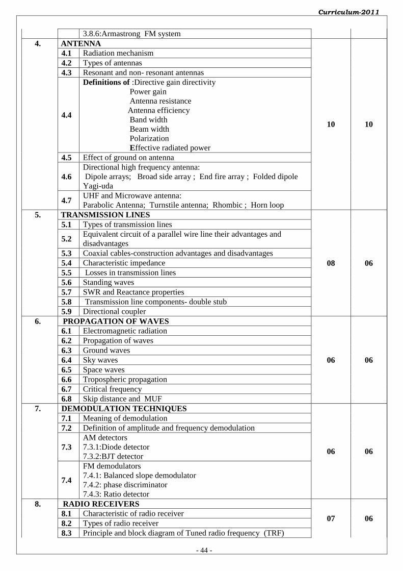
Curriculum-2011
- 44 -
3.8.6:Armastrong FM system
4. ANTENNA
10 10
4.1 Radiation mechanism
4.2 Types of antennas
4.3 Resonant and non- resonant antennas
4.4
Definitions of :Directive gain directivity
Power gain
Antenna resistance
Antenna efficiency
Band width
Beam width
Polarization
Effective radiated power
4.5 Effect of ground on antenna
4.6
Directional high frequency antenna:
Dipole arrays; Broad side array ; End fire array ; Folded dipole
Yagi-uda
4.7 UHF and Microwave antenna:
Parabolic Antenna; Turnstile antenna; Rhombic ; Horn loop
5. TRANSMISSION LINES
08 06
5.1 Types of transmission lines
5.2 Equivalent circuit of a parallel wire line their advantages and
disadvantages
5.3 Coaxial cables-construction advantages and disadvantages
5.4 Characteristic impedance
5.5 Losses in transmission lines
5.6 Standing waves
5.7 SWR and Reactance properties
5.8 Transmission line components- double stub
5.9 Directional coupler
6. PROPAGATION OF WAVES
06 06
6.1 Electromagnetic radiation
6.2 Propagation of waves
6.3 Ground waves
6.4 Sky waves
6.5 Space waves
6.6 Tropospheric propagation
6.7 Critical frequency
6.8 Skip distance and MUF
7. DEMODULATION TECHNIQUES
06 06
7.1 Meaning of demodulation
7.2 Definition of amplitude and frequency demodulation
7.3
AM detectors
7.3.1:Diode detector
7.3.2:BJT detector
7.4
FM demodulators
7.4.1: Balanced slope demodulator
7.4.2: phase discriminator
7.4.3: Ratio detector
8. RADIO RECEIVERS
07 06 8.1 Characteristic of radio receiver
8.2 Types of radio receiver
8.3 Principle and block diagram of Tuned radio frequency (TRF)

Curriculum-2011
- 45 -
8.4 Principle and block diagram of Super heterodyne receivers
8.5 Electronic tuning
8.6 Image frequency and its rejection
8.7 Double spotting frequency
8.8 Stereophonic FM receiver
8.9 Compare AM and FM receiver
Total 80 64
B. LIST OF PRACTICALS/LABORATORY EXPERIENCES/ASSIGNMENTS: (Any ten)
S.No. Title of Practical/Lab. Work/Assignments Hrs.
1. To obtain AM waves and calculate modulation index. 02
2. To obtain FM waves and calculate modulation index. 02
3. To obtain demodulated wave from AM wave. 02
4. To obtain demodulated wave from FM wave. 02
5. To find the faults in radio receiver. 02
6. To study Radio receiver detector circuit. 02
7. To study Balance Modulator circuit. 02
8. To obtain gain and beam width of antenna. 04
9. To obtain front to back ratio of antenna. 02
10. To obtain radiation with distance of Yagi-Uda Antenna. 04
11. To measure the attenuation along the transmission line. 04
12. To measure the stationary waves along the transmission line. 04
Total 32
ASSESSMENT OF LABORATORY EXPERIENCES/ASSIGNMENTS :
Continuous assessment of Term Work and Term end oral/ practical examination.
SUGGESTED IMPLEMENTATION STRATEGIES :
1. Lecture method
2. Improved lecture method.
3. Q & A technique.
4. Demonstration
5. Case study
6. Seminars
7. Field visit
SUGGESTED LEARNING RESOURCES :
1. PRINT: Text books/Reference books/Manuals/Journals.
2. NON PRINT : CDs / PPT / Transperencies / Charts / Models
C. SPECIFICATION TABLE :
Chapter
No. Title of Chapter
Marks (1.5 x Marks
allotted to
chapter)
Distribution of Marks
Knowledge Comprehension Application Total
1. Communication
Fundamentals
15 08 07 -- 15
2. Amplitude modulation 27 10 13 04 27
3. Frequency modulation 23 08 12 03 23
4. Antenna 15 05 10 -- 15
5. Transmission Lines 12 04 08 -- 12
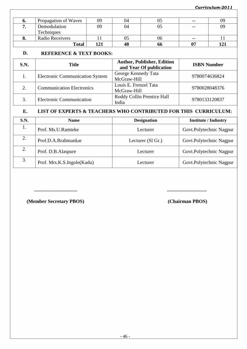
Curriculum-2011
- 46 -
6. Propagation of Waves 09 04 05 -- 09
7. Demodulation
Techniques
09 04 05 -- 09
8. Radio Receivers 11 05 06 -- 11
Total 121 48 66 07 121
D. REFERENCE & TEXT BOOKS:
S.N. Title Author, Publisher, Edition
and Year Of publication ISBN Number
1. Electronic Communication System George Kennedy Tata
McGraw-Hill 9780074636824
2. Communication Electronics Louis E. Frenzel Tata
McGraw-Hill 9780028048376
3. Electronic Communication Roddy Collin Prentice Hall
India 9780133120837
E. LIST OF EXPERTS & TEACHERS WHO CONTRIBUTED FOR THIS CURRICULUM:
S.N. Name Designation Institute / Industry
1. Prof. Ms.U.Ramteke Lecturer Govt.Polytechnic Nagpur
2. Prof.D.A.Brahmankar Lecturer (Sl Gr.) Govt.Polytechnic Nagpur
2. Prof. D.B.Alaspure Lecturer Govt.Polytechnic Nagpur
3. Prof. Mrs.K.S.Ingole(Kadu) Lecturer Govt.Polytechnic Nagpur
-------------------------- ------------------------
(Member Secretary PBOS) (Chairman PBOS)
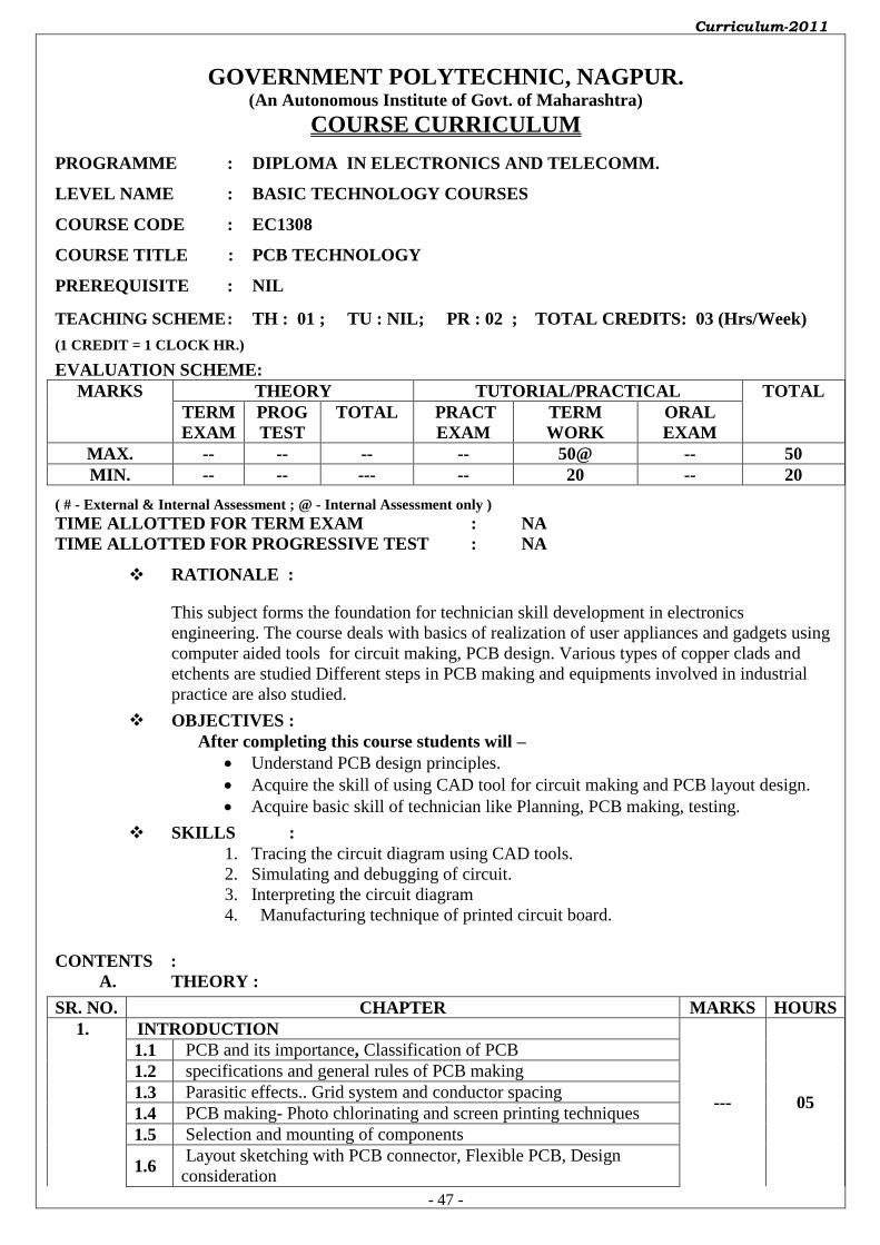
Curriculum-2011
- 47 -
GOVERNMENT POLYTECHNIC, NAGPUR. (An Autonomous Institute of Govt. of Maharashtra)
COURSE CURRICULUM
PROGRAMME : DIPLOMA IN ELECTRONICS AND TELECOMM.
LEVEL NAME : BASIC TECHNOLOGY COURSES
COURSE CODE : EC1308
COURSE TITLE : PCB TECHNOLOGY
PREREQUISITE : NIL
TEACHING SCHEME : TH : 01 ; TU : NIL; PR : 02 ; TOTAL CREDITS: 03 (Hrs/Week)
(1 CREDIT = 1 CLOCK HR.)
EVALUATION SCHEME: MARKS THEORY TUTORIAL/PRACTICAL TOTAL
TERM
EXAM
PROG
TEST
TOTAL PRACT
EXAM
TERM
WORK
ORAL
EXAM
MAX. -- -- -- -- 50@ -- 50
MIN. -- -- --- -- 20 -- 20
( # - External & Internal Assessment ; @ - Internal Assessment only ) TIME ALLOTTED FOR TERM EXAM : NA TIME ALLOTTED FOR PROGRESSIVE TEST : NA
RATIONALE :
This subject forms the foundation for technician skill development in electronics
engineering. The course deals with basics of realization of user appliances and gadgets using
computer aided tools for circuit making, PCB design. Various types of copper clads and
etchents are studied Different steps in PCB making and equipments involved in industrial
practice are also studied.
OBJECTIVES :
After completing this course students will –
Understand PCB design principles.
Acquire the skill of using CAD tool for circuit making and PCB layout design.
Acquire basic skill of technician like Planning, PCB making, testing.
SKILLS :
1. Tracing the circuit diagram using CAD tools.
2. Simulating and debugging of circuit.
3. Interpreting the circuit diagram
4. Manufacturing technique of printed circuit board.
CONTENTS :
A. THEORY :
SR. NO. CHAPTER MARKS HOURS
1. INTRODUCTION
--- 05
1.1 PCB and its importance, Classification of PCB
1.2 specifications and general rules of PCB making
1.3 Parasitic effects.. Grid system and conductor spacing
1.4 PCB making- Photo chlorinating and screen printing techniques
1.5 Selection and mounting of components
1.6 Layout sketching with PCB connector, Flexible PCB, Design
consideration
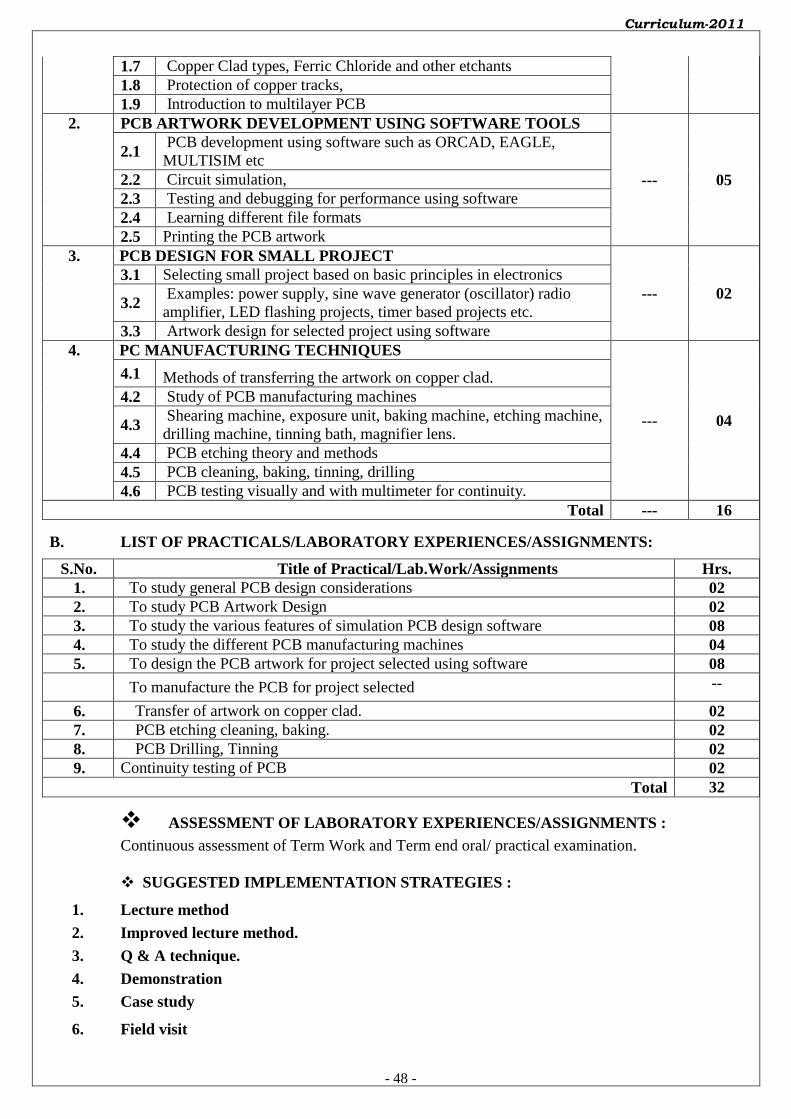
Curriculum-2011
- 48 -
1.7 Copper Clad types, Ferric Chloride and other etchants
1.8 Protection of copper tracks,
1.9 Introduction to multilayer PCB
2. PCB ARTWORK DEVELOPMENT USING SOFTWARE TOOLS
--- 05
2.1 PCB development using software such as ORCAD, EAGLE,
MULTISIM etc
2.2 Circuit simulation,
2.3 Testing and debugging for performance using software
2.4 Learning different file formats
2.5 Printing the PCB artwork
3. PCB DESIGN FOR SMALL PROJECT
--- 02
3.1 Selecting small project based on basic principles in electronics
3.2 Examples: power supply, sine wave generator (oscillator) radio
amplifier, LED flashing projects, timer based projects etc.
3.3 Artwork design for selected project using software
4. PC MANUFACTURING TECHNIQUES
--- 04
4.1 Methods of transferring the artwork on copper clad.
4.2 Study of PCB manufacturing machines
4.3 Shearing machine, exposure unit, baking machine, etching machine,
drilling machine, tinning bath, magnifier lens.
4.4 PCB etching theory and methods
4.5 PCB cleaning, baking, tinning, drilling
4.6 PCB testing visually and with multimeter for continuity.
Total --- 16
B. LIST OF PRACTICALS/LABORATORY EXPERIENCES/ASSIGNMENTS:
S.No. Title of Practical/Lab.Work/Assignments Hrs.
1. To study general PCB design considerations 02
2. To study PCB Artwork Design 02
3. To study the various features of simulation PCB design software 08
4. To study the different PCB manufacturing machines 04
5. To design the PCB artwork for project selected using software 08
To manufacture the PCB for project selected --
6. Transfer of artwork on copper clad. 02
7. PCB etching cleaning, baking. 02
8. PCB Drilling, Tinning 02
9. Continuity testing of PCB 02
Total 32
ASSESSMENT OF LABORATORY EXPERIENCES/ASSIGNMENTS :
Continuous assessment of Term Work and Term end oral/ practical examination.
SUGGESTED IMPLEMENTATION STRATEGIES :
1. Lecture method
2. Improved lecture method.
3. Q & A technique.
4. Demonstration
5. Case study
6. Field visit

Curriculum-2011
- 49 -
SUGGESTED LEARNING RESOURCES :
1. PRINT : Text books/Reference books/Manuals/Journals.
2. NON PRINT : CDs / PPT / Transperencies / Charts / Models
C. SPECIFICATION TABLE : NOT APPLICABLE
Chapter
No. Title of Chapter
Marks (1.5 x Marks
allotted to
chapter)
Distribution of Marks
Knowledge Comprehension Application Total
NOT APPLICABLE
D. REFERENCE & TEXT BOOKS:
S.N. Title Author, Publisher, Edition
and Year Of publication ISBN Number
1. PCB Technology Khandpur Tata McHill 9780070588141
2. PCB Design &Technology W.C.Bosshart Tata McHill 0074515497
2. Software user manual
3. Data manual from different
manufacurer
4. Hand books on PCB design
E. LIST OF EXPERTS & TEACHERS WHO CONTRIBUTED FOR THIS CURRICULUM:
S.N. Name Designation Institute / Industry
1. V.J.Dongre Lecturer(Sl Grade) Ggvt. Polytechnic ,Nagpur
2. D.A. Brahmankar Lecturer(Sl Grade) Ggvt. Polytechnic ,Nagpur
-------------------------- ------------------------
(Member Secretary PBOS) (Chairman PBOS)