Embed Size (px)
Citation preview

i
GOVERNMENT OF INDIA
MINISTRY OF RAILWAYS
शाकू कप्ऱर के लऱए अनुरऺण पे्रक्टिस एवम ऩी ओ एच मेनुअऱ
Maintenance Practices & Manual for POH of Schaku Couplers
कैमिेक/एम/प्रोज/2019-20/एमऩी8/1.0
अटिूबर 2019
CAMTECH/M/PROJ/2019-20/MP8/1.0
October 2019
Maharajpur, Gwalior (M.P.) - 474005
ii
शाकू कप्ऱर के लऱए अनुरऺण पे्रक्टिस एवम ऩी ओ एच मेनुअऱ
Maintenance Practices & Manual for POH of Schaku Couplers
कैमिेक/एम/प्रोज/2019-20/एमऩी8/1.0
अटिूबर 2019
CAMTECH/M/PROJ/2019-20/MP8/1.0
October 2019

i
FOREWORD
Semi-Permanent Coupler (Schaku Coupler) play an important role in running of
DEMU/EMU. The failure of Semi-Permanent Coupler (Schaku Coupler has a great
impact on the reliability of the DEMU/EMU. This Manual has been prepared for
Supervisors and artisan staff of DEMU/EMU sheds and workshops who are involved
in the maintenance of Semi-Permanent Coupler (Schaku Coupler). This Manual not
only cover maintenance of Semi-Permanent Coupler (Schaku Coupler) but care has
been taken to explain basic things including its storage and handling. All
information of components has been covered in this Manual. The book is also
useful for newly appointed artisan. With these important features, I am sure that
the handbook will give necessary help to the concerned staff to ensure problem
free service of the Schaku Coupler.
CAMTECH is continuously making efforts in documentation and up-gradation of information on advanced maintenance practices. This document
contains a Maintenance practices, types of Schaku Coupler and their salient
features etc. being used on Indian Railways.
I am confident that the information given in this Maintenance manual will
help field staff of Mechanical department in improving their knowledge as well as
in correct and efficient maintenance of Schaku Coupler in their Sheds/Workshops.
CAMTECH Lucknow Jitendra Singh
Date: 30.10.2019 Principal Executive Director
ii
PREFACE
The importance of Schaku Couplers cannot be denied in the efficient
operation of DEMU/EMU in railways. On Indian Railways Schaku Couplers have
replaced conventional at a large number of Diesel car Shed and workshops due to
their wide applications and safety reasons. In the current scenario, Schaku Couplers
of different approved manufacturers have been installed in Indian Railways.
To refresh the knowledge of staff involved in maintenance of Schaku
Couplers, CAMTECH has prepared this maintenance Manual which consists of
Maintenance aspects of different approved manufacturers. This manual is also
consist of description of components and their availably to ensure the reliability
and availability to achieve the correct maintenance of Schaku Couplers.
We are sincerely thankful to Officers and supervisors of North Central Railway, West Central Railway, Central railway and Western Railway and all the manufactures of Schaku Couplers who helped us in preparing this manual. Since technological upgradation and learning is a continuous process, you may feel the need for some addition/modification in this question bank. If so, please give your comments on email address [email protected] or write to us at Indian Railways Centre for Advanced Maintenance Technology, In front of Adityaz Hotel, Airport Road, Maharajpur, Gwalior (M.P.) 474005.
CAMTECH Gwalior Manoj Kumar
Date: 30.10.2019. Joint Director (Mechanical)

iii
Contents
Section Sub- Section Description
Pages
Foreword i
Preface ii
Contents iii
Correction Slip iv
Disclaimer & Our objective v
CAMTECH Publications vi
1 2 3
4.0
5.0
- -
3.1 3.2 3.3 3.4
4.1
4.1.1 4.1.2 4.2 4.3
4.3.1 4.3.2 4.3.3 4.3.4 4.3.5 4.3.6 4.3.7 4.4
4.4.1 4.5
4.5.1 4.5.2 4.5.3 4.5.4 4.5.5 4.5.6 4.5.7 4.5.8
5.1
Introduction Type of Coupler Salient features of Semi-Permanent Coupler Escorts Sanrok Westing House Blue Bird Main Parts of Semi-Permanent Coupler Main Sub Assemblies of Semi-Permanent Coupler Coupler – End ‘A’ Coupler- End ‘B’ Features of Semi-Permanent Coupler Description & Functional Features of Sub Assemblies Bearing Bracket (Used both in End ‘A’ & End ‘B’) Draw and buffing gear (Used both in End ‘A’ & End ‘B’ Intermediate Tube (Used both in End ‘A’ & End ‘B’) Air Pipe Coupling (Used both in End ’A’ & End ‘B’) Centering Device (Used only in End ‘B’) Adjustable Cup Sleeve (Used only in End ’A’) Center Adjustment Device (Used both in End ‘A’ & End ‘B’) Maintenance Schedules Trip schedule to “C” schedule Periodically Overhauling Overhauling Procedures Polyamide bushes Bearing Bracket with Support Draw and Buffer gear Lower & upper Cup-sleeves Spring sleeves Intermediate tube sub assembly Painting & Assembly Inspection and Replacement of Components and Sub assemblies Inspection and replacement of components of Main Bracket / Bearing Bracket with support drg. No 2ED-181-1001 {SCHAKU DRG. NO. 40-
1
1
1
1
2
2
3
4
4
4
5
6
6
6
7
8
9
9
10
11
12
12
12
12
12
12
13
13
13
13
13
13

iv
6.0
8.0
9.0
10.0 11.0
5.2
5.2.1 5.2.1.1
5.2.1.2 5.2.1.3
5.3
5.3.1
5.4
5.4.1
- 7.0
8.1 8.2
9.1 9.2 9.3 9.4
- -
588.07(2)} Inspection and replacement of components of Draft Gear / Draw and Buff Gear drawing No. 2ED-181-1011 {SCHAKU DRG. NO. 40-586.06(2)} Fixtures and method of use
Fixtures and Method of Using Fixture for pressing Articulation Bearing (Fixture Drawing No. SE-F-134) Procedure for assembly of Draft Gear/ Draw & Buff Gear Method of using the fixture for Draft Gear / Draw & Buff Gear sub assy. Inspection and replacement of components of Centering Device drg. No 2ED-181-1006 { SCHAKU Drg. No. 40-1000.10(2)} Method of using the assembly fixture for Centering Device (Fixture Drawing No. SE-F-135) Inspection and replacement of components of Intermediate Tube Drg. No 2ED-181-1004 {SCHAKU 40-586.01:01(2)}. Device for removal of bearing bolt (Fixture Drawing No. SE-F-140) Lubrication Scheme Spring Condemning Criteria Tools and Gauges for Maintenance For Depot For Workshop Tools, Fixtures and Gauges & method of using gauges Pressing Method of using the Fixture and the Articulation Bearing Assembly Fixture For Draw & Buff Gear
Method of Using the Fixture for Draw & Buff gear Sub-assy. Method of Using the Assembly Fixture for Centering Device Part List & Recommended percentage of Holding for POH Rejectable defects
14
14
14
16
23
23
23
24
24
27
27
27
27
28
28
28
28
38
39
41

v
सुधार ऩर्चियों को जारी करना
ISSUE OF CORRECTION SLIPS
इस प्रश्न फैंक के लरए बविष्म भें जायी की जाने िारी सुधाय ऩर्चिमों के क्रभाॊक इस प्रकाय से यहेंगे:
The correction slips to be issued in future for this question bank will be numbered as follows:
केमिेक/एम/प्रोज/2019-20/एमऩी 8/1.0 # XX दि .................
CAMTECH/M/PROJ/2019-20/MP8/1.0# XX date .......
जहाॊ “XX” सम्फॊर्धत सुधाय ऩची की क्रभ सॊख्मा है (01 से शुरू होकय) Where “XX” is the serial number of the concerned correction slip (starting from 01 onwards).
सुधार ऩचीयाॉ जारी की गयीॊ
CORRECTION SLIPS ISSUED
सुधाय ऩची की क्रभ सॊख्मा
Sr. No. of
Correction
Slip
जायी कयने की तायीख
Date of
issue
सॊशोर्धत ऩषृ्ठ क्रभाॊक एिॊ भद सॊख्मा
Page no. and Item No.
modified
टिप्ऩणिमाॉ Remarks

vi
डिस्कटऱेमर
मह स्ऩष्ि ककमा जाता है कक इस हस्तऩसु्स्तका भें दी गमी जानकायी, येरिे फोर्ि प्रकाशनों तथा आय र्ी एस ओ प्रकाशनों के ककसी बी ितिभान आरेखों को विस्थावऩत नहीॊ कयतीॊ है | मह दस्तािेज िधैाननक नहीॊ है ियन इसभें टदए गए ननदेश केिर भागि दशिन हेत ुहैं | मटद ककसी बफन्द ुऩय वियोधाबास दृष्िीगोचय होता है, तफ येरिे फोर्ि प्रकाशनों, आय र्ी एस ओ भागिदशिन अथिा जोनर येरिे के ननदेशों का ऩारन कयें |
DISCLAIMER It is clarified that the information given in this handbook does not supersede any existing provisions laid down in the Railway Board and RDSO publications. This document is not statuary and instructions given are for the purpose of guidance only. If at any point contradiction is observed, then Railway Board/RDSO guidelines may be referred or prevalent Zonal Railways instructions may be followed.
----------------------------------------------------------------------------------------------------
हमारा उद्िेश्य
अनयुऺि प्रौद्मोर्गकी औय कामिप्रिारी का उन्नमन कयना तथा उत्ऩादकता औय येरिे की ऩरयसम्ऩवि एिॊ जनशस्तत के ननष्ऩादन भें सधुाय कयना स्जससे अॊतवििषमों भें विश्िसनीमता , उऩमोर्गता औय दऺता प्राप्त की जा सके |
OUR OBJECTIVE To upgrade Maintenance Technologies and Methodologies and achieve improvement in Productivity and Performance of all Railway assets and manpower which inter-alia would cover Reliability, Availability and Utilisation.
मटद आऩ इस सन्दबि भें कोई विचाय औय सझुाि देना चाहत ेहैं तो कृऩमा हभें इस ऩत ेऩय लरखें : सॊऩकि सतू्र : सॊमतुत ननदेशक (माॊबत्रक)
ऩत्राचाय का ऩता : बायतीम येर उच्च अनयुऺि प्रौद्मोर्गकी कें द्र,
भहायाजऩयु, ग्िालरमय (भ. प्र.) वऩन कोर् 474020
िेरीपोन : 0751-2470890
पैतस : 0751-2470841
ई-भेर : [email protected]
If you have any suggestion & any specific comments, please write to us:
Contact person : Joint Director (Mechanical) Postal Address : Centre for Advanced Maintenance Technology, Maharajpur,
Gwalior (M.P.) Pin Code – 474 020
Phone : 0751 - 2470890
Fax : 0751 – 2470841 Email : [email protected]

vii
कैमिेक प्रकाशन CAMTECH Publications
CAMTECH is continuing its efforts in the documentation and up-gradation of information on maintenance
practices of Signalling & Telecom assets. Over the years a large number of publications on Signalling &
Telecom subjects have been prepared in the form of handbooks, pocket books, pamphlets and video films.
These publications have been uploaded on the internet as well as railnet.
For downloading these publications
On Internet:
Visit www.rdso.indianrailways.gov.in
Go to Directorates → CAMTECH → OtherImportant Links→ Publications for download → Mechanical
Engineering Or http://www.rdso.indianrailways.gov.in/view_section.jsp?lang=0&id=0,2,17,5025
On Railnet:
Visit RDSO website at 10.100.2.19
Go to Directorates → CAMTECH → Publications → Mechanical Engineering
Or http://10.100.2.19/camtech/Publications/CAMTECH%20Publications%20Online/CAMTECHMain.htm
A limited number of publications in hard copy are also available in CAMTECH library which can be got
issued by deputing staff with official letter from controllong officer. The letter should be addressed to Joint
Director (Mechanical), CAMTECH, Gwalior.
For any further information regarding publications please contact:
Joint Director (Mechanical) – 0751-2470890 (O)(BSNL)
SSE/Mechanical - 8989473656
Or
Email at [email protected]
Or
FAX to 0751-2470841 (BSNL)
Or
Write at
Joint Director (Mechanical)
Indian Railways Centre for Advanced Maintenance Technology,
In front of Hotel Adityaz, Airport Road, Maharajpur,
Gwalior (M.P.) 474005

CAMTECH/M/PROJ/19-20/MP8 1
Maintenance Practices and manual of SCHAKU Coupler October 2019
Maintenance Practices and manual of SCHAKU Coupler
1.0 Introduction
Semi Permanent Coupler:- DEMU/EMU stock are provided with the Semi Permanent Couplers manufactured by Messers Scharfenburg Kupplung, GmbH, Germany (short formed as “SCHAKU”). When two coaches are coupled by Semi Permanent Couplers, one coach is fitted with “Semi Permanent Coupler – End ‘A’ & the other one is fitted with “Semi Permanent Coupler–End ‘B’.
Semi Permanent Coupler is designed to ensure a permanent connection of railcars which in traffic form a unit and therefore need not be separated unless in an emergency or in the workshop.
The Drawbar / Intermediate Tube are connected by means of an Adjustable muff coupling/Pair of Cup Sleeve set. The set can be detached easily thus allowing quick separation of the cars for repair.
The Drawbar / Intermediate Tube are provided with a centring hole and a centring pin which help to align the drawbars
When being connected and protect the shank of the Drawbars / Intermediate Tube against twisting. Besides the main mechanical connection, the Semi Permanent Coupler also ensures the safe connection of the main air reservoir pipes.
Semi Permanent Coupler is based on the Generic Semi Permanent Couplers being
used on the EMU stock of the Indian Railways currently.
Semi Permanent Coupler is fully interchangeable with the Semi Permanent Coupler of current suppliers.
2.0 Type of Coupler : Following make semi-permanent couplers are being used in Indian Railways.
1. Escorts make
2. Wasting house
3.Blue bird
4. Sanrok
3.0 Salient feature : Salient features of above make couplers are as below-
3.1 Escorts make :
1. Compressed load 100 tons and tensile load 70 tons
2. Dynamic absorption capacity of the rubber draft gear of these couplers is 800 m-kg.
3. Due to rigid connection of this coupler there exists negligible play between them in coupling position and hence no appreciable wear and tear during train operation.

CAMTECH/M/PROJ/19-20/MP8 2
Maintenance Practices and manual of SCHAKU Coupler October 2019
4. Due to rigid and stress transmitting mechanical connection between the coaches by fitting semi-permanent couplers, protection to the coach and the load against undue impacts is secured.
5. Due to high capacity incorporated in semi-permanent couplers, it allows coaches to buffer at high speeds (from 3 km/hr to 15 km/hr) without any damage to the coach and the load.
6. Interlocking arrangement of these couplers prevents to some extent the mounting or telescoping of the coaches when involved in accidents.
7. As the fulcrum of these couplers is located far in the rear of the coach, coupler side displacements in curves and consequently the transverse forces acting on the wheel flange are kept minimum. This reduces the wear of the wheel flange and minimizes the chances of derailment.
8. As the coupling links of semi-permanent couplers from a parallelogram with equilibrium of forces, unintentional disengagement of coaches due to shocks is rendered impossible.
9. The design and construction of the pivoted joint between these couplers and coach permits vertical deflection of ±75 mm and horizontal deflection of 284 mm or 13º on either side and as a consequence enables the coaches to couple up at all track curves and also on points of change of gradient even at maximum height difference between the two coaches.
3.2 Sanrok : S.N Description Specification
Value Detail
1. Coupling Length from pivot point mm
------ 1107 mm
2. Static strength in Buff Mode 100 Tonne 120 Tonne 3. Static strength in Draw Mode 70 Tonne 100 Tonne 4. Ultimate or Fracture strength 150 Tonne 150 Tonne 5. Stroke of the Draw Gear mm 75 max 56 6. Horizontal Swing (o) -- 15 7. Vertical Swing (o) ---- 5-7 8. Energy absorption capacity
dynamic 800 mkg 900 mkg
9. Height from top the rail mm ---- 1035 10. End Force – Sill load 50,000 kg 500 kN +10/-5 kN 11. Coach to Coach interconnection ------ Thru adjustable muff
coupling 3.3 Westing House 1. Semi –permanent couplers are used to couple coaching stock of Electric Multiple
Units which are at present, operating with Central, Western, Eastern, South Eastern, Southern Railways in India.
CAMTECH/M/PROJ/19-20/MP8 3
Maintenance Practices and manual of SCHAKU Coupler October 2019
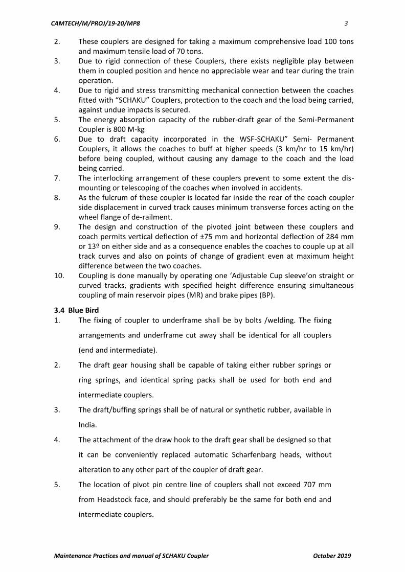
2. These couplers are designed for taking a maximum comprehensive load 100 tons and maximum tensile load of 70 tons.
3. Due to rigid connection of these Couplers, there exists negligible play between them in coupled position and hence no appreciable wear and tear during the train operation.
4. Due to rigid and stress transmitting mechanical connection between the coaches fitted with “SCHAKU” Couplers, protection to the coach and the load being carried, against undue impacts is secured.
5. The energy absorption capacity of the rubber-draft gear of the Semi-Permanent Coupler is 800 M-kg
6. Due to draft capacity incorporated in the WSF-SCHAKU” Semi- Permanent Couplers, it allows the coaches to buff at higher speeds (3 km/hr to 15 km/hr) before being coupled, without causing any damage to the coach and the load being carried.
7. The interlocking arrangement of these couplers prevent to some extent the dis-mounting or telescoping of the coaches when involved in accidents.
8. As the fulcrum of these coupler is located far inside the rear of the coach coupler side displacement in curved track causes minimum transverse forces acting on the wheel flange of de-railment.
9. The design and construction of the pivoted joint between these couplers and coach permits vertical deflection of ±75 mm and horizontal deflection of 284 mm or 13º on either side and as a consequence enables the coaches to couple up at all track curves and also on points of change of gradient even at maximum height difference between the two coaches.
10. Coupling is done manually by operating one ‘Adjustable Cup sleeve’on straight or curved tracks, gradients with specified height difference ensuring simultaneous coupling of main reservoir pipes (MR) and brake pipes (BP).
3.4 Blue Bird 1. The fixing of coupler to underframe shall be by bolts /welding. The fixing
arrangements and underframe cut away shall be identical for all couplers
(end and intermediate).
2. The draft gear housing shall be capable of taking either rubber springs or
ring springs, and identical spring packs shall be used for both end and
intermediate couplers.
3. The draft/buffing springs shall be of natural or synthetic rubber, available in
India.
4. The attachment of the draw hook to the draft gear shall be designed so that
it can be conveniently replaced automatic Scharfenbarg heads, without
alteration to any other part of the coupler of draft gear.
5. The location of pivot pin centre line of couplers shall not exceed 707 mm
from Headstock face, and should preferably be the same for both end and
intermediate couplers.

CAMTECH/M/PROJ/19-20/MP8 4
Maintenance Practices and manual of SCHAKU Coupler October 2019
6. The distance between the Headstocks of adjacent coaches shall be 800 mm
when Semi-permanent couplers are fitted, and not less than 964 mm for
the end couplers when fitted with automatic heads.
7. The semi-permanent couplers shall be provided with arrangement for
coupling of brake pipes. If required provision should also be made for
coupling of electrical cables for which 76 electrical contacts should be
catered for.
4.0 Main Parts
4.1 MAIN SUB ASSEMBLIES OF SEMI PERMANENT COUPLER
4.1.1 Coupler – End ‘A’ consist of: -
Bearing Bracket with Support – Sub Assembly
Draw and Buffer Gear – Sub Assembly.
Intermediate Tube – Sub Assembly.
Air Pipe Coupling – Sub Assembly.
Center Adjustment Device – Sub Assembly.
Adjustable Cup sleeve – Sub Assembly

CAMTECH/M/PROJ/19-20/MP8 5
Maintenance Practices and manual of SCHAKU Coupler October 2019
4.1.2 Coupler- End ‘B’ consist of: - Bearing Bracket with Support – Sub Assembly. Draw and Buffer Gear – Sub Assembly.
Intermediate Tube – Sub Assembly. Air Pipe Coupling – Sub Assembly.
Center Adjustment Device – Sub Assembly. Centering Device – Sub Assembly.
CAMTECH/M/PROJ/19-20/MP8 6
Maintenance Practices and manual of SCHAKU Coupler October 2019
4.2 FEATURES OF SEMI- PERMANENT COUPLERS
This coupler is designed for taking a maximum tensile load of 70 tons.
Due to rigid connection of these Couplers, there exist negligible play between them in coupled position and hence no appreciable wear and tear during the train operation.
CAMTECH/M/PROJ/19-20/MP8 7
Maintenance Practices and manual of SCHAKU Coupler October 2019
The absorption capacity of the rubber draft gear of the Semi Permanent Couplers is 800 M-kg.
The design and construction of the pivot joint between these Couplers and coaches is achieved by using the “Articulation Bearing” and permits a total deflection of ± 75 mm
and horizontal deflection of 284 mm or 13 on either side. This enables the coaches to couple up easily at all track curves and also on points of changing gradient even at the maximum height difference between two coaches.
4.3 DESCRIPTION & FUNCTIONAL FEATURES OF SUB ASSEMBLIES
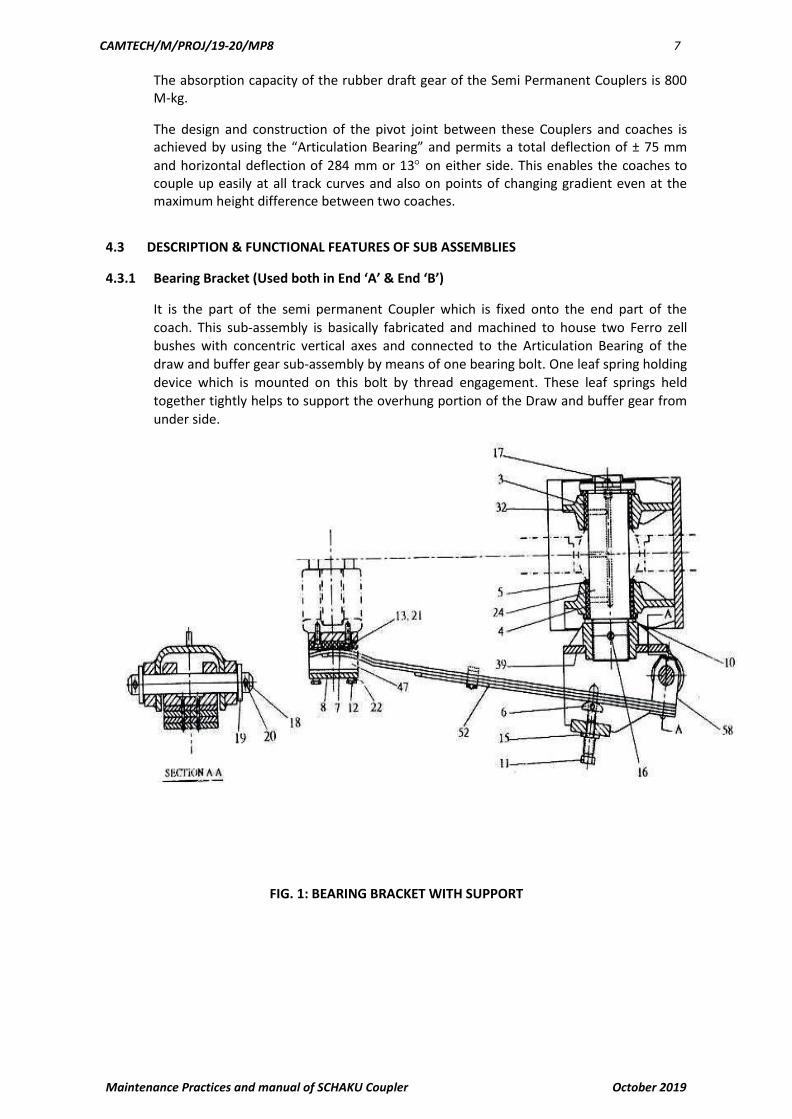
4.3.1 Bearing Bracket (Used both in End ‘A’ & End ‘B’)
It is the part of the semi permanent Coupler which is fixed onto the end part of the
coach. This sub-assembly is basically fabricated and machined to house two Ferro zell bushes with concentric vertical axes and connected to the Articulation Bearing of the draw and buffer gear sub-assembly by means of one bearing bolt. One leaf spring holding device which is mounted on this bolt by thread engagement. These leaf springs held together tightly helps to support the overhung portion of the Draw and buffer gear from
under side.
FIG. 1: BEARING BRACKET WITH SUPPORT
CAMTECH/M/PROJ/19-20/MP8 8
Maintenance Practices and manual of SCHAKU Coupler October 2019
Nomenclature of fig. 1
Description Ref.No. Description Ref.No.
Bush 3 Pin 32 d 9 x 200 x 180 17
Bush 4 Unmachined Disc 33 18
Disc Thrust Piece 5 Split Pin 8 x 50 19
Slide Plate 6 Fan Disc V10, 5 20
Plate 7 Spring Washer A8 21
Plate Disc 8 Bearing Bolt (Sub Assly.) 22
Hex. Hd Screw A M30 x 90 10 Bearing bracket (sub Assly.) 24
Hex. Hd Screw A M8 x 15 11 Carrier (Sub Assly.) 32
Csk Hd Screw M10 x 30 12 Fastening (Sub Assly.) 47
Hex. Nut M30 13 Leaf Spring Comp. (Sub Assly.) 52
Split Pin 3/8” dia x 5-1/2” 15 Block (Sub Assly.) 58
Grease Nipple A10 16
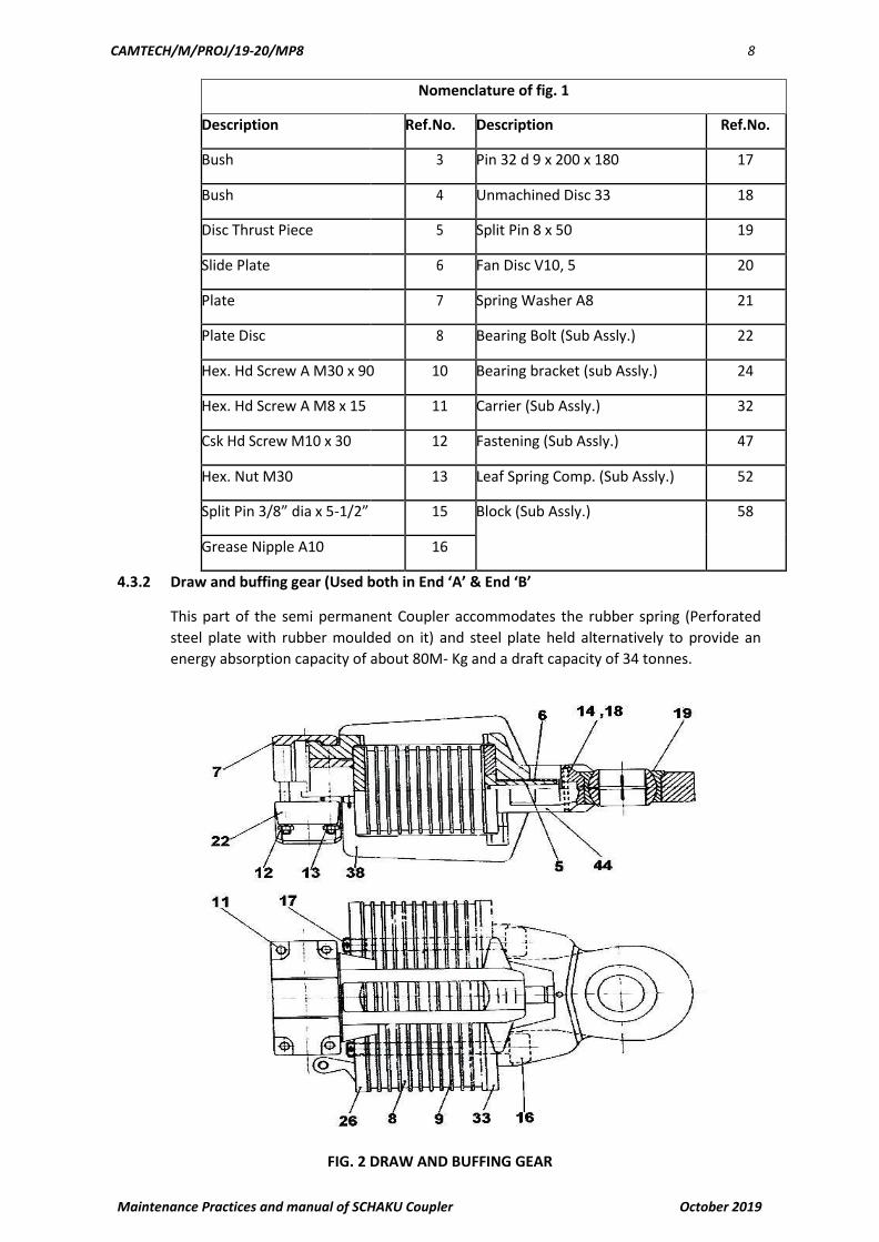
4.3.2 Draw and buffing gear (Used both in End ‘A’ & End ‘B’
This part of the semi permanent Coupler accommodates the rubber spring (Perforated
steel plate with rubber moulded on it) and steel plate held alternatively to provide an
energy absorption capacity of about 80M- Kg and a draft capacity of 34 tonnes.
FIG. 2 DRAW AND BUFFING GEAR

CAMTECH/M/PROJ/19-20/MP8 9
Maintenance Practices and manual of SCHAKU Coupler October 2019
Nomenclature of fig. 2
DESCRIPTION REF.NO DESCRIPTION REF.NO
Bolt 5 Socket Head Screw M42 x 300 16
Bush 6 Split Pin 10 x 70 17
Upper Part of the Cup Sleeve 7 Clamping Pin 5 x 40 18
Spencer Moulton Rubber Pivoting Bearing – Const’n.
Springs 8 Type-A 19
Spencer Mild Steel lates3/16” 9 Lower Part of Cup Sleeve 22
Hex. Head Screw M16 x 180 11 Front Plate (Sub Assly.) 26
Hex. Nut M16 12 Rear Plate (Sub Assly.) 33
Spring Washer A16 13 Yoke (Sub Assly.) 38
Clamping Pin 8 x 80 14 Eye (Sub Assly.) 44
It comprises of a fabricated yoke which houses the said Rubber springs, plates, one front plate and one rear plate, a fork eye which houses the “Articulation Bearing”. This fork eye is mounted on the yoke by means of two Socket head screws, which also keep the Rubber-spring and plate in position. There is a pin with a polyamide bush, which keeps the fork eye in central axis of the yoke. During the train operation the rubber spring along with plates are subjected to compression only in both the cases when the coupler is under tensile load or compressive load. The draw and buffer gear is connected to bearing bracket in one side and rigidly to the intermediate tube on the other side.
4.3.3 Intermediate Tube (Used both in End ‘A’ & End ‘B’)
The intermediate tube is fabricated by welding two forged rings on both side of a
seamless (heavy) tube piece. Then subsequent stress relieving and machining is done on
it. Intermediate tube being rigidly connected to the draw and buffer gear assembly,
become one single solid stock extending from the pivot center (i.e. articulation bearing)
up to its other free end.
FIG. 3 INTERMEDIATE TUBE ASSLY.
CAMTECH/M/PROJ/19-20/MP8 10
Maintenance Practices and manual of SCHAKU Coupler October 2019
Nomenclature of fig. 3
DESCRIPTION REF.NO. DESCRIPTION REF.NO.
Tube 1 Spring Sleeve 10 x 20 10
Ring 2 Lug 5
Plate 3
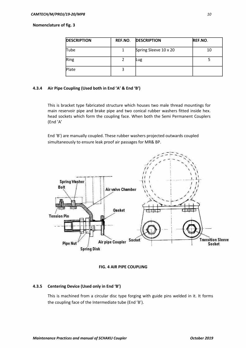
4.3.4 Air Pipe Coupling (Used both in End ’A’ & End ‘B’)
This is bracket type fabricated structure which houses two male thread mountings for main reservoir pipe and brake pipe and two conical rubber washers fitted inside hex. head sockets which form the coupling face. When both the Semi Permanent Couplers (End ’A’
End ‘B’) are manually coupled. These rubber washers projected outwards coupled
simultaneously to ensure leak proof air passages for MR& BP.
FIG. 4 AIR PIPE COUPLING
4.3.5 Centering Device (Used only in End ‘B’)
This is machined from a circular disc type forging with guide pins welded in it. It forms
the coupling face of the Intermediate tube (End ’B’).
CAMTECH/M/PROJ/19-20/MP8 11
Maintenance Practices and manual of SCHAKU Coupler October 2019
FIG . 5 CENTERING DEVICE
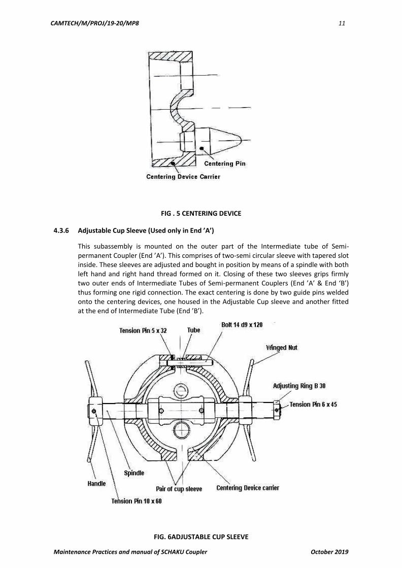
4.3.6 Adjustable Cup Sleeve (Used only in End ’A’)
This subassembly is mounted on the outer part of the Intermediate tube of Semi-permanent Coupler (End ’A’). This comprises of two-semi circular sleeve with tapered slot inside. These sleeves are adjusted and bought in position by means of a spindle with both left hand and right hand thread formed on it. Closing of these two sleeves grips firmly two outer ends of Intermediate Tubes of Semi-permanent Couplers (End ’A’ & End ‘B’) thus forming one rigid connection. The exact centering is done by two guide pins welded onto the centering devices, one housed in the Adjustable Cup sleeve and another fitted at the end of Intermediate Tube (End ’B’).
FIG. 6ADJUSTABLE CUP SLEEVE

CAMTECH/M/PROJ/19-20/MP8 12
Maintenance Practices and manual of SCHAKU Coupler October 2019
4.3.7 Center Adjustment Device (Used both in End ‘A’ & End ‘B’)
This consists of two concentric helical compression springs housed in a barrel with clevis end fitting to facilitate mounting onto the underside of the frame. This combination of springs fitted with a push rod always exert are storing force to keep the coupler end in central position which often gets moved sidewise due to relative lateral displacement of
two compartments during the train operation.
FIG. 7 CENTER ADJUSTMENT DEVICE
Nomenclature of fig. 7
DESCRIPTION REF.NO.
Compression Spring 1
Compression Spring 2
Disc Spring 4
M24 x Hex. Nut 6
Hook Spring Nut 7
Bolt, B22, h11 x 65 x 58.5 8
M23 washer 9
Split Pin 5 x36 10
Plug (Sub Assly.) Complete Comprising 12
Eye 30
Spring Casing (Sub Assly.) Comp. Comprising 16
Spring Casing (Sub Assly.) Comp. Comprising 21
Fork Head 25
Clamping Screw 29
CAMTECH/M/PROJ/19-20/MP8 13
Maintenance Practices and manual of SCHAKU Coupler October 2019
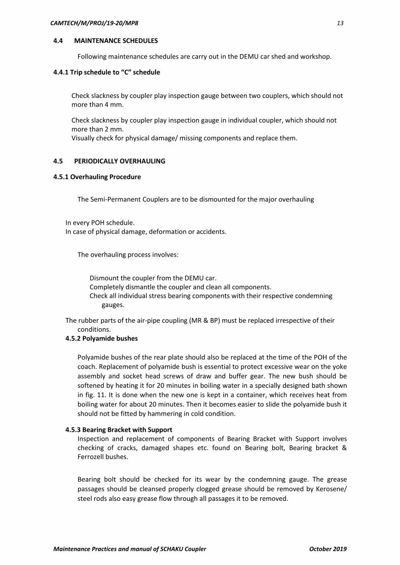
4.4 MAINTENANCE SCHEDULES
Following maintenance schedules are carry out in the DEMU car shed and workshop.
4.4.1 Trip schedule to “C” schedule
Check slackness by coupler play inspection gauge between two couplers, which should not more than 4 mm.
Check slackness by coupler play inspection gauge in individual coupler, which should not more than 2 mm.
Visually check for physical damage/ missing components and replace them.
4.5 PERIODICALLY OVERHAULING
4.5.1 Overhauling Procedure
The Semi-Permanent Couplers are to be dismounted for the major overhauling
In every POH schedule. In case of physical damage, deformation or accidents.
The overhauling process involves:
Dismount the coupler from the DEMU car. Completely dismantle the coupler and clean all components. Check all individual stress bearing components with their respective condemning
gauges.
The rubber parts of the air-pipe coupling (MR & BP) must be replaced irrespective of their conditions.
4.5.2 Polyamide bushes
Polyamide bushes of the rear plate should also be replaced at the time of the POH of the
coach. Replacement of polyamide bush is essential to protect excessive wear on the yoke
assembly and socket head screws of draw and buffer gear. The new bush should be
softened by heating it for 20 minutes in boiling water in a specially designed bath shown
in fig. 11. It is done when the new one is kept in a container, which receives heat from
boiling water for about 20 minutes. Then it becomes easier to slide the polyamide bush it
should not be fitted by hammering in cold condition.
4.5.3 Bearing Bracket with SupportInspection and replacement of components of Bearing Bracket with Support involves checking of cracks, damaged shapes etc. found on Bearing bolt, Bearing bracket & Ferrozell bushes.
Bearing bolt should be checked for its wear by the condemning gauge. The grease
passages should be cleansed properly clogged grease should be removed by Kerosene/
steel rods also easy grease flow through all passages it to be removed.

CAMTECH/M/PROJ/19-20/MP8 14
Maintenance Practices and manual of SCHAKU Coupler October 2019
4.5.4 Draw and Buffer gear
The rubber spring and steel plate combination should be checked for: -
Total height of 7 steel plates + rubber spring + front plate + rear plate = Minimum 256.8 mm in unstressed condition.
Energy absorption capacity to be compared with the graph, plotted by the standard one as given in SCHAKU Drg. No. 40-586.06(2).
External condition and appearance of the rubber springs are to be checked for aging and should be replaced by new one if found not satisfactory.
4.5.5 Lower & upper Cup-sleeves
The pair of lower & upper Cup-sleeves should be checked by the condemning gauges. These Cup-sleeves along with socket head screws are to be replaced by new ones if found excessively worn out. Lubrication of Articulation bearing is to be ensured. The gap
between the inner race and the ball should not exceed 0.3 mm. In case this gap is bigger one new articulation bearing is to be fitted. NDT and Die- penetration test on yoke structure should be carried out and if found with any cracks etc. it is to be replaced by new yoke.
4.5.6 Spring sleevesThe spring sleeves used in all the sub assemblies are to be checked for proper shape and
appearance. They should be replaced if not found in satisfactory condition.
4.5.7 Intermediate tube sub assemblyComponent of Intermediate tube sub assembly of Semi Permanent Coupler (End ‘A’ &
End ‘B’) should be replaced if found not satisfactory to withstand the service conditions.
Welded joints should be checked for cracks etc. by NDT & Die-penetration test. Use of
hammer to open Adjustable Cup- sleeves is to be avoided as far as possible.
4.5.8 Painting & AssemblyAfter complete overhauling of the Semi-Permanent Coupler. One coat of black Enamel should be applied all over to protect the main body from rusting. Grease must be applied to all moving parts. Date of overhaul should be punched/ stamped on the Intermediate tube to maintain the overhauling records.
After complete overhauling, the Semi-Permanent Coupler should be assembled again and
kept in a clean & dry place till the time of fitment on the coaches.
5.0 Inspection and Replacement of Components and Sub assemblies 5.1 Inspection and replacement of components of Main Bracket / Bearing
Bracket with support drg. No 2ED-181-1001 {SCHAKU DRG. NO. 40-588.07(2)}. Bearing bolt should be checked for its wear by the condemning gauge. The
grease passage should be absolutely clear. Clogged grease should be
removed by kerosene/steel rods. Also ensure that the grease when applied
through the grease nipple flows easily.
CAMTECH/M/PROJ/19-20/MP8 15
Maintenance Practices and manual of SCHAKU Coupler October 2019
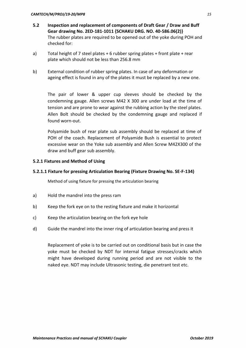
5.2 Inspection and replacement of components of Draft Gear / Draw and Buff Gear drawing No. 2ED-181-1011 {SCHAKU DRG. NO. 40-586.06(2)} The rubber plates are required to be opened out of the yoke during POH and checked for:
a) Total height of 7 steel plates + 6 rubber spring plates + front plate + rear plate which should not be less than 256.8 mm
b) External condition of rubber spring plates. In case of any deformation or ageing effect is found in any of the plates it must be replaced by a new one.
The pair of lower & upper cup sleeves should be checked by the
condemning gauge. Allen screws M42 X 300 are under load at the time of
tension and are prone to wear against the rubbing action by the steel plates.
Allen Bolt should be checked by the condemning gauge and replaced if
found worn-out.
Polyamide bush of rear plate sub assembly should be replaced at time of
POH of the coach. Replacement of Polyamide Bush is essential to protect
excessive wear on the Yoke sub assembly and Allen Screw M42X300 of the
draw and buff gear sub assembly.
5.2.1 Fixtures and Method of Using
5.2.1.1 Fixture for pressing Articulation Bearing (Fixture Drawing No. SE-F-134)
Method of using fixture for pressing the articulation bearing
a) Hold the mandrel into the press ram
b) Keep the fork eye on to the resting fixture and make it horizontal
c) Keep the articulation bearing on the fork eye hole
d) Guide the mandrel into the inner ring of articulation bearing and press it
Replacement of yoke is to be carried out on conditional basis but in case the
yoke must be checked by NDT for internal fatigue stresses/cracks which
might have developed during running period and are not visible to the
naked eye. NDT may include Ultrasonic testing, die penetrant test etc.

CAMTECH/M/PROJ/19-20/MP8 16
Maintenance Practices and manual of SCHAKU Coupler October 2019

CAMTECH/M/PROJ/19-20/MP8 17
Maintenance Practices and manual of SCHAKU Coupler October 2019
Assembly fixture for Draft Gear / Draw and Buff Gear (Fixture Drawing No.SE-F-137 & SE-F-138)
5.2.1.2 Procedure for assembly of Draft Gear/ Draw & Buff Gear
a) Assemble the six spring rubber plates and seven steel plates on two clamps
drg. No SE-G-138 with two pins drawings in the two holes in plates and
press them with the help of a press to a height of 247.3 mm and lock them
by tightening the nuts of the clamps (use Drg. SE-G-136 For checking
dimension 247.3mm)
b) Place yoke in the frame (drg. SE-G-137 Sheet 1) at 90° to normal position along with front and rear plates
c) Place the clamped assembly as per 1 above on the yoke & with the help of press, start introducing it smoothly into the yoke.
d) The lower clamp touches the yoke, and then slides up gradually and ultimately comes out with upper clamp.
e) Ensure proper alignment of holes in the plates & yoke and remove the pins.

CAMTECH/M/PROJ/19-20/MP8 18
Maintenance Practices and manual of SCHAKU Coupler October 2019
f) Assemble the yoke with the fork eye by introducing Allen screws. Tighten Allen screws.
g) The plates should not be loose in the yoke. If so dismantle & reassemble the parts with new plates.

CAMTECH/M/PROJ/19-20/MP8 19
Maintenance Practices and manual of SCHAKU Coupler October 2019

CAMTECH/M/PROJ/19-20/MP8 20
Maintenance Practices and manual of SCHAKU Coupler October 2019
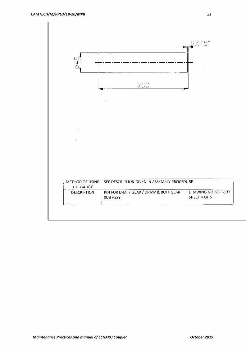
CAMTECH/M/PROJ/19-20/MP8 21
Maintenance Practices and manual of SCHAKU Coupler October 2019

CAMTECH/M/PROJ/19-20/MP8 22
Maintenance Practices and manual of SCHAKU Coupler October 2019

CAMTECH/M/PROJ/19-20/MP8 23
Maintenance Practices and manual of SCHAKU Coupler October 2019

CAMTECH/M/PROJ/19-20/MP8 24
Maintenance Practices and manual of SCHAKU Coupler October 2019
5.2.1.3 Method of using the fixture for Draft Gear / Draw & Buff Gear sub assy.
a) Keep the buffer plates into the holding clamps and inserts the two pins inside.
b) Press the buffer plates and tighten up the nuts
c) Keep the resting blocks on to the press.
d) Keep the yoke on to it.
e) Keep the top block on to the yoke.
f) Now keep the draw & buff gear partial sub-assembly into it and press it
5.3 Inspection and replacement of components of Centering Device drg. No 2ED-181-1006 { SCHAKU Drg. No. 40-1000.10(2)}
Components of Centering Device drg. No 2ED-181-1006 should be replaced on
conditional basis except all the compression springs. The springs which are
always under compressive and tensile loads must be checked for their
strength and should be replaced if they cross the condemning limits as
given in spring condemning criteria.
5.3.1Method of using the assembly fixture for Centering Device (Fixture Drawing No. SE-F-135)
a) Pass the bolt through the spring pot and compression spring (inner & outer)
b) Put the spring plate and tighten up the lock nut
c) Place the complete sub assembly on to the fixture
d) Compress the compression springs with the help of the fixture up to the stop and tighten up the lock nut.
e) Remove the compressed sub assembly from the fixture for final assembly in to the spring casing.
CAMTECH/M/PROJ/19-20/MP8 25
Maintenance Practices and manual of SCHAKU Coupler October 2019
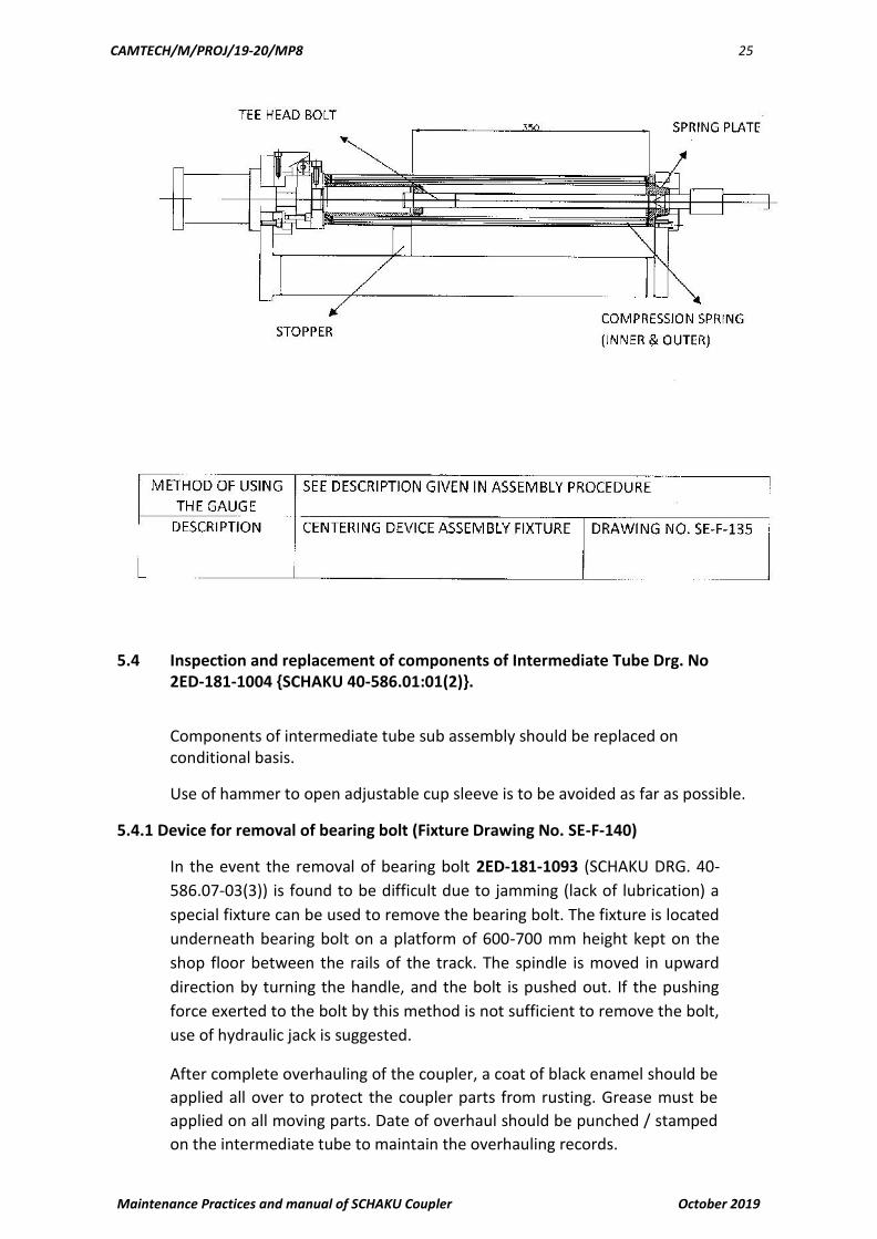
5.4 Inspection and replacement of components of Intermediate Tube Drg. No
2ED-181-1004 {SCHAKU 40-586.01:01(2)}.
Components of intermediate tube sub assembly should be replaced on conditional basis.
Use of hammer to open adjustable cup sleeve is to be avoided as far as possible.
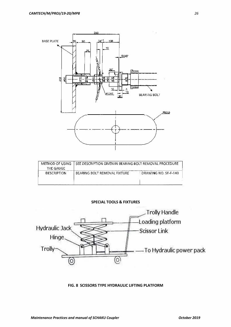
5.4.1 Device for removal of bearing bolt (Fixture Drawing No. SE-F-140)
In the event the removal of bearing bolt 2ED-181-1093 (SCHAKU DRG. 40-
586.07-03(3)) is found to be difficult due to jamming (lack of lubrication) a
special fixture can be used to remove the bearing bolt. The fixture is located
underneath bearing bolt on a platform of 600-700 mm height kept on the
shop floor between the rails of the track. The spindle is moved in upward
direction by turning the handle, and the bolt is pushed out. If the pushing
force exerted to the bolt by this method is not sufficient to remove the bolt,
use of hydraulic jack is suggested.
After complete overhauling of the coupler, a coat of black enamel should be
applied all over to protect the coupler parts from rusting. Grease must be
applied on all moving parts. Date of overhaul should be punched / stamped
on the intermediate tube to maintain the overhauling records.
CAMTECH/M/PROJ/19-20/MP8 26
Maintenance Practices and manual of SCHAKU Coupler October 2019
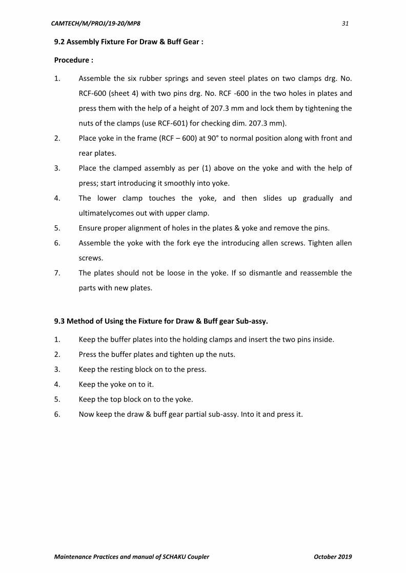
SPECIAL TOOLS & FIXTURES
FIG. 8 SCISSORS TYPE HYDRAULIC LIFTING PLATFORM

CAMTECH/M/PROJ/19-20/MP8 27
Maintenance Practices and manual of SCHAKU Coupler October 2019
FIG. 9 HYDRAULICALLY POWERED PRESS
FIG. 9 FIXTURE FOR DISMANTLING & ASSEMBLY OF MAIN SOCKET HEAD CAP SCREW OF DRAFT GEAR
FIG.10 BATH FOR SOFTENING OF POLYMIDE BUSH

CAMTECH/M/PROJ/19-20/MP8 28
Maintenance Practices and manual of SCHAKU Coupler October 2019
6.0 Lubrication Scheme
S NO Part Name Periodicity Type of Lubricant
01 Bush Polyamide POH Servo GP grease 2 or HP GP Gerase
or equivalant
02 Bearing Bolt 6 months --------do------
03 Leaf Springs 6 months --------do------
04 Articulation Bearing At the time of POH of the Molykote (Mos2) paste, make OKS
coach or equivalent
7.0 SPRING CONDEMNING CRITERIA:
Springs are to be condemned on condition basis. Springs with corrosion and pitting are to be rejected. Springs are to be checked for serviceability as per the table given below:
Spring Similar Schaku Length (L) Load (min) Free Length (min)
Drawing No. Drawing No. mm kg at L mm
2ED-181-1069 AB-784/13-088.03- 29.5 (comp.) 10 61
14(4)
2ED-181-1115 40-3000.10-1(3) 351 60 510
2ED-181-1116 40-3000.10-2(3) 351 38 510
8.0 Tools and Gauges for Maintenance
8.1 For Depots
S.No. Description
Drawuing No.
1. Fixture for pressing the Articulation bearing RCF 599
2. Assembly fixture for Draw & Buff gear RCF 600,601
3. Fixture for centering device RCF 602
4. Condemning gauges for -
1. Allen Screw SK 338
2. Cup Sleeve 40.SK.2551.01
3. Pair of cup sleeves 40.2251.02
4. Bolt 40.SK.2551.1
5. Front plate S.A (dia 138d) 40.SK.2551.5
6. Front plate & forked head (dia 22h11) 40.SK.2551.6

CAMTECH/M/PROJ/19-20/MP8 29
Maintenance Practices and manual of SCHAKU Coupler October 2019
7. Rear plate SA (dia 30H11) 40.2551.7
8. Yoke S.A 40.SK.2551.8
9. Articulation bearing 40.SK.2551.9
10. Bush (dia 80 B9) [Ferrozal] 40.SK.2551.10
11. Carrier S.A. & Leaf spring 40.SK.2551.11
12. Bearing bolt 40.SK.2551.12
8.2 For Workshops
List of Devices, Fixtures and Standard Tools required for Overhauling of Semi-Permanent
Coupler
Standard Tooling
Spanners : 1. 11-13 mm
2. 18-19 mm
3. 22-24 mm
4.30-32 mm
5. 34-36 mm
Hammer : Approx. 1 kg
Screw Driver 6 mm, 32 mm
Hand Press 6 mm, 32 mm
Bench Vice 6 mm, 32 mm
Allen Keys 6 mm, 32 mm
Fixture
1. Fixture for pressing the draw & buff gear v sub –assy. Into the yoke : RCF 600.
2. GO gauge for draw & buff gear sub-assy : RCF 601
3. Fixture for assembly of centering device & spring holder : RCF 602
4. Fixture for articulation bearing RCF 599 ( for pressing in fork eye)Description of
9.0 Tools, Fixtures and Gauges & method of using gauges
9.1 Pressing Method of using the Fixture and the Articulation Bearing
1. Press the fork eye in which the Articulation Bearing is to be pressed on the set of
adjustment bolts.
2. Position the spring loaded locater in the bore of fork eye.
3. Adjust the adjustment bolts to achieve a free movement of locater within the
bore of fork eye.
4. Place the articulation Bearing on the collar of locater as in figure.
5. Press the articulation Bearing with the help of pressing mandrel.
6. The spring loaded locater will automatically slide down
7. Ensure that Articulation Bearing has fully engaged and in position (observe the
collar)

CAMTECH/M/PROJ/19-20/MP8 30
Maintenance Practices and manual of SCHAKU Coupler October 2019
CAMTECH/M/PROJ/19-20/MP8 31
Maintenance Practices and manual of SCHAKU Coupler October 2019
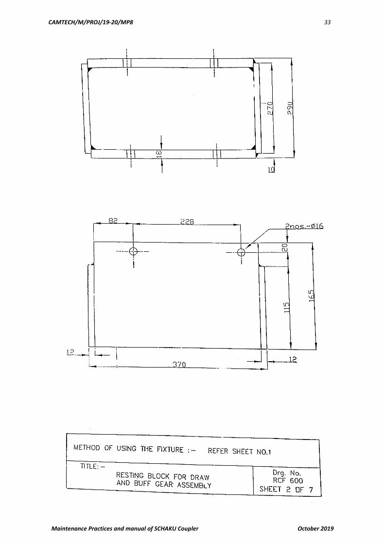
9.2 Assembly Fixture For Draw & Buff Gear :
Procedure :
1. Assemble the six rubber springs and seven steel plates on two clamps drg. No.
RCF-600 (sheet 4) with two pins drg. No. RCF -600 in the two holes in plates and
press them with the help of a height of 207.3 mm and lock them by tightening the
nuts of the clamps (use RCF-601) for checking dim. 207.3 mm).
2. Place yoke in the frame (RCF – 600) at 90° to normal position along with front and
rear plates.
3. Place the clamped assembly as per (1) above on the yoke and with the help of
press; start introducing it smoothly into yoke.
4. The lower clamp touches the yoke, and then slides up gradually and
ultimatelycomes out with upper clamp.
5. Ensure proper alignment of holes in the plates & yoke and remove the pins.
6. Assemble the yoke with the fork eye the introducing allen screws. Tighten allen
screws.
7. The plates should not be loose in the yoke. If so dismantle and reassemble the
parts with new plates.
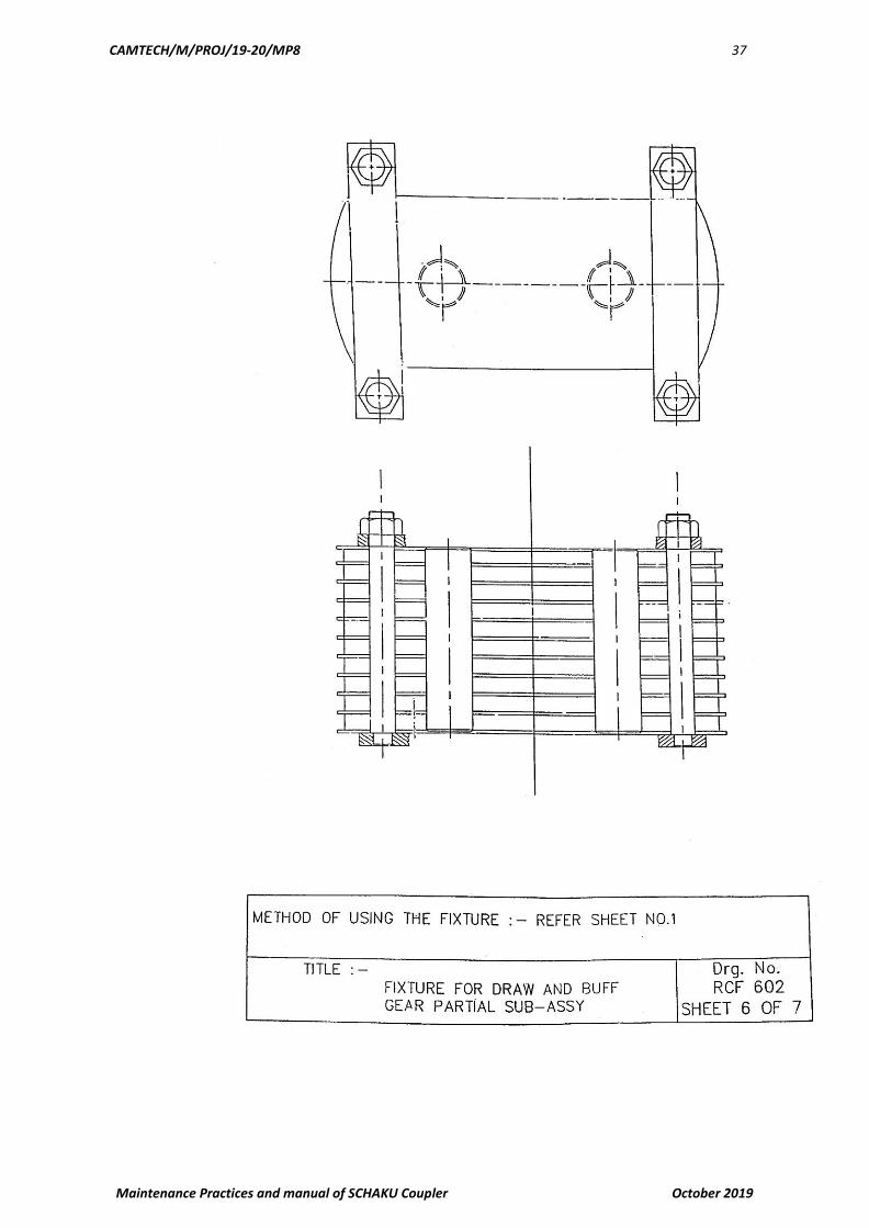
9.3 Method of Using the Fixture for Draw & Buff gear Sub-assy.
1. Keep the buffer plates into the holding clamps and insert the two pins inside.
2. Press the buffer plates and tighten up the nuts.
3. Keep the resting block on to the press.
4. Keep the yoke on to it.
5. Keep the top block on to the yoke.
6. Now keep the draw & buff gear partial sub-assy. Into it and press it.

CAMTECH/M/PROJ/19-20/MP8 32
Maintenance Practices and manual of SCHAKU Coupler October 2019
CAMTECH/M/PROJ/19-20/MP8 33
Maintenance Practices and manual of SCHAKU Coupler October 2019

CAMTECH/M/PROJ/19-20/MP8 34
Maintenance Practices and manual of SCHAKU Coupler October 2019

CAMTECH/M/PROJ/19-20/MP8 35
Maintenance Practices and manual of SCHAKU Coupler October 2019

CAMTECH/M/PROJ/19-20/MP8 36
Maintenance Practices and manual of SCHAKU Coupler October 2019
CAMTECH/M/PROJ/19-20/MP8 37
Maintenance Practices and manual of SCHAKU Coupler October 2019

CAMTECH/M/PROJ/19-20/MP8 38
Maintenance Practices and manual of SCHAKU Coupler October 2019

CAMTECH/M/PROJ/19-20/MP8 39
Maintenance Practices and manual of SCHAKU Coupler October 2019
9.4 Method of Using the Assembly Fixture for Centering Device
1. Place the Tee Head Bolt on the Guide Pin ensure that the centre of the Bolt is on
the centre of the Guide Pin.
2. Insert the spring pot and spring on the Tee Head Bolt.
3. Place the spring plate on the Tee Head Bolt, slightly press it insert it inside the
fixture and then place Centering pin on the upper side of Tee Head bolt.
4. Apply pressure in the cylinder due to which the Tee Head Bolt will move upward
then, then remove the centring pin and tighten the nut on bolt.
5. Release the pressure and then remove the assembly.

CAMTECH/M/PROJ/19-20/MP8 40
Maintenance Practices and manual of SCHAKU Coupler October 2019
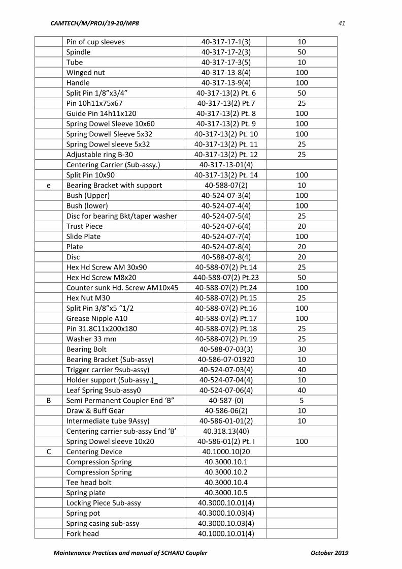
10.0 Part List & Recommended percentage of Holding for POH
S.No. Description Ref Drawing No. Recommended % holding for
POH
A. Semi Permanent Coupler End ‘A’ 40-586-(O) 5
a. Draw & Buff Gear 40.586-06(2) 10
Bolt 40.586-06-3(4) 25
Bush (Polymide) 40.586-06-4(40 100
Cup Sleeve Upper Part 13-128-15 (30 25
Rubber Sp. Plate 40-SK-1837(1) A 80
Steel Plate 3/16” 40-SK-1837(1) B 25
Hex Hd. Screw M16x180 40.586-0692) Pt. 15 25
Hex. Nut M16 40.586-06(2) Pt.12 25
Hex. Nut Spring washer A16 40-586-06(2) Pt. 13 25
Spring dowel pin 8x80 40-586-06920 Pt. 14 100
Allen Screw M42x300 40.586-06(2) Pt.16 25
Split pin 40.586-06(2) Pt. 17 100
Spring Dowel Pin 5x40 40.586-06(2) Pt. 18 100
Articulation Bearing (sub-assy.) 40-SK-1960(3) 50
Seal 40-SK-1960-3(3) 100
Cup Sleeve Lower (Sub-assy 40-SK-1960-01(4) 25
Front Plate (sub-assy) 40-586-06-02(4) 10
Rear Plate (Sub-assy) 40-SK-06-02(4)) 10
Yoke (Sub-assy) 40-586-06-04(2) 10
Fork Eye (Sub-assy) 40-586-06-0592) 35
Name plate SK-147 10
Disc for bearing Bkt/Taper washer 40-524-07-0594) 10
Yoke (Sub-assy) 40-586-06-04(2) 10
Fork Eye (Sub-assy.) 40-586-06-05(2) 35
Name plate SK 147 10
Self tapping screws 4x5/18” long 25
Bush SK 331 50
b Intermediate Tube (Assy.) 40-586-01-01(2) 10
Spring dowel Sleeve 10x20 40-586-01-01(2) Pt.1 100
c Air pipe coupling SK-198 25
Angle plate (welded) SK-199 10
Rubber tube 13-088-03-15940 100
Spring 13-088-03-14(4) 30
Sleeve 13-088-03-1394) 25
Sealing ring 13-088-03-16(4) 100
Spring pot SK-365 20
Washer SK-366 20
Hex Nut R1” DIN 431 20
Elbow R1”x3/4” 20
Elbow R1”x1’ DIN 1569 20
Hex Hd. Screw M12x25 SK-198 Pt.10 25
Spring washer B 12 SK-198 Pt.11 25
Spring dowel sleeve 8x25 SK-198Pt. 12 25
d Adjustable cup sleeve 40-317-13(2) 10
CAMTECH/M/PROJ/19-20/MP8 41
Maintenance Practices and manual of SCHAKU Coupler October 2019
Pin of cup sleeves 40-317-17-1(3) 10
Spindle 40-317-17-2(3) 50
Tube 40-317-17-3(5) 10
Winged nut 40-317-13-8(4) 100
Handle 40-317-13-9(4) 100
Split Pin 1/8”x3/4” 40-317-13(2) Pt. 6 50
Pin 10h11x75x67 40-317-13(2) Pt.7 25
Guide Pin 14h11x120 40-317-13(2) Pt. 8 100
Spring Dowel Sleeve 10x60 40-317-13(2) Pt. 9 100
Spring Dowell Sleeve 5x32 40-317-13(2) Pt. 10 100
Spring Dowel sleeve 5x32 40-317-13(2) Pt. 11 25
Adjustable ring B-30 40-317-13(2) Pt. 12 25
Centering Carrier (Sub-assy.) 40-317-13-01(4)
Split Pin 10x90 40-317-13(2) Pt. 14 100
e Bearing Bracket with support 40-588-07(2) 10
Bush (Upper) 40-524-07-3(4) 100
Bush (lower) 40-524-07-4(4) 100
Disc for bearing Bkt/taper washer 40-524-07-5(4) 25
Trust Piece 40-524-07-6(4) 20
Slide Plate 40-524-07-7(4) 100
Plate 40-524-07-8(4) 20
Disc 40-588-07-8(4) 20
Hex Hd Screw AM 30x90 40-588-07(2) Pt.14 25
Hex Hd Screw M8x20 440-588-07(2) Pt.23 50
Counter sunk Hd. Screw AM10x45 40-588-07(2) Pt.24 100
Hex Nut M30 40-588-07(2) Pt.15 25
Split Pin 3/8”x5 “1/2 40-588-07(2) Pt.16 100
Grease Nipple A10 40-588-07(2) Pt.17 100
Pin 31.8C11x200x180 40-588-07(2) Pt.18 25
Washer 33 mm 40-588-07(2) Pt.19 25
Bearing Bolt 40-588-07-03(3) 30
Bearing Bracket (Sub-assy) 40-586-07-01920 10
Trigger carrier 9sub-assy) 40-524-07-03(4) 40
Holder support (Sub-assy.)_ 40-524-07-04(4) 10
Leaf Spring 9sub-assy0 40-524-07-06(4) 40
B Semi Permanent Coupler End ‘B” 40-587-(0) 5
Draw & Buff Gear 40-586-06(2) 10
Intermediate tube 9Assy) 40-586-01-01(2) 10
Centering carrier sub-assy End ‘B’ 40.318.13(40)
Spring Dowel sleeve 10x20 40-586-01(2) Pt. I 100
C Centering Device 40.1000.10(20
Compression Spring 40.3000.10.1
Compression Spring 40.3000.10.2
Tee head bolt 40.3000.10.4
Spring plate 40.3000.10.5
Locking Piece Sub-assy 40.3000.10.01(4)
Spring pot 40.3000.10.03(4)
Spring casing sub-assy 40.3000.10.03(4)
Fork head 40.1000.10.01(4)

CAMTECH/M/PROJ/19-20/MP8 42
Maintenance Practices and manual of SCHAKU Coupler October 2019
Washer 23
Split pin dia 6x35
Hex. Nut M24
Spring ring dia 104
Bolt 22h 11x65x58.5
11.0 Rejectable defects
Overhauling and Reconditioning Criteria of the Components of Semi-Permanent Coupler:-
S.No. Description Drg. No. Similar SCHAKu Drg. No.
Criteria for Determining the Condition
Fixture / Gauge Required
1. Tragger/ Carrier (Sub Assembly)
2ED-181-1200 40-524.07:03(4) Hole dia 32mm is to be Checked Condemn the component if the gauge passes through.
Limit Gauge to Drg. No. SE-G-117
2. Holder Support (Sub Assy.)
2ED-181-1102 40-524.07:04(4) Visible Cracks or damage
Visual
3. Bush Upper 2ED-181-1091 40-524.07-3(4) Internal Diameter 80 +0.200 / +0.274mm is to be Checked. Condemn Bush if gauge passes through it. There should not be any visible crack or damage.
Limit Gauge to Drg. No. SE-G-118
4. Bush Lower 2ED-181-1089 40-524.07-4(4) Internal Diameter 80 +0.200 / +0.274mm is to be Checked. Condemn Bush if gauge passes through it. There should not be any visible crack or damage.
Limit Gauge to Drg. No. SE-G-118
5. Disc Upper/ Taper Disc
2ED-181-1087 40-524.07-5(4) Visible Cracks or damage
Visual
6. Thrust Piece 2ED-181-1095 40-524.07-6(4) Visible Cracks or damage
Visual
7. Slide Plate (Ferrozal)
2ED-181-1246 40-524.07-7(4) Plate Thickness of 10mm is to be Checked. Replaced if wear exceeding 3mm.
Vernier calliper
8. Plate 2ED-181-1216 40-524.07-8(4) Visible Cracks or damage
Visual
9. Leaf Spring Complete (Sub Assy.)
2ED-181-1106 40-524.07.06(3) If wear of more than 2mm on the top leaf it has to be replaced
Vernier Calliper
10. Bearing Bracket/ Main Bracket
2ED-181-1088 40-586.07:01(2) Internal Fatigue stresses / Cracks.
NDT (Ultrasonic testing, Die penetrant test etc.)

CAMTECH/M/PROJ/19-20/MP8 43
Maintenance Practices and manual of SCHAKU Coupler October 2019
11. Bearing Bolt 2ED-181-1093 40-586.07:03(3) External diameter Ø80 mm is to be checked. Condemn Bolt if it passes through the gauge.
Snap gauge to drg. No. SE-G-119
12. Disc Lower/Flat Disc
2ED-181-1086 40-588.07-3(4) Visible Cracks or damage
Visual
13. Plate 2ED-181-1105 AB/742 Visible Cracks or damage
Visual
14. Pin (31.8c11x200) DIN 1433 40-588.07(2) Prt. 18
External diameter Ø31.8 c11 mm is to be checked. Condemn Pin if gauge passes through
Snap Gauge to drg. No. SE-G-120
15. Cup Sleeve Lower (Sub Assy.)
2ED-181-1153 40-586.06:01(4) External diameter Ø31.8 c11 mm is to be checked. Condemn Pin if gauge passes through
Profile Gauge to drg. No. SE-G-121
16. Front Plate (Sub Assy.)
2ED-181-1156 40-586.06:02(4) External diameter of tube 138mm and diameter 22H11 of bush is to be checked. Condemn Front Plate Sub. Assy. If gauge passes over it.And Check for Straightness of Plates, Visible Cracks or damage.
Limit Snap Gauge to Drg. No. SE-G- 122 Limit gauge to Drg. No. SE-G-132
17. Rear Plate (Sub Assy.)
2ED-181-1157 2ED-181-1157 Inner Diameter Ø30mm of guide tube is to be checked. Condemn Rear Plate Sub. Assy. If gauge passes over it. And Check for Straightness of Plates, Visible Cracks/damage
Limit Snap Gauge to Drg. No. SE-G- 123
18. Bush Polymide 2ED-181-1182 40-586.06-4(4) Check the exsesive wear and for Visible Crack or Damage
--------------------
19. Yoke (Sub assy.) 2ED-181-1183 40-586.06:04(2) Internal diameter Ø138mm and Ø47 mm are to be checked. Condemn Yoke if the Gauge Passes Through it.Internal Fatigue stresses / Cracks.
Limit gauge to drg. No. SE-G-124 NDT (Ultrasonic testing, Die penetrant test etc.)

CAMTECH/M/PROJ/19-20/MP8 44
Maintenance Practices and manual of SCHAKU Coupler October 2019
20. Fork Eye with Bolt (Sub Assy.)
2ED-181-1383 2-SK.399 ------------------ -----------
21. Fork Eye 2ED-181-1168 40-586.06:05(2) Internal Fatigue stresses / Cracks.
NDT (Ultrasonic testing, Die penetrant test etc.)
22. Bolt 2ED-181-1181 40-586.06-3(4) Outer Diameter Ø30mm d11 is to be checked. Condemn bolt if gauge passes over bolt
Snap Gauge to drg. No. SE-G-126
23. Cup Sleeve Upper 2ED-181-1149 40-624.06-4(3) Check the Profile & for Visible Crack/damage
Profile Gauge to drg. No. SE-G-121
24. Rubber Spring Plate
2ED-181-1245 40-SK-1837(1) Length of unstressed spring should not go below 256.8 mm. Check for Straightness of Plates, Visible Cracks or damage.
Vernier Calliper
25. Steel Plate 2ED-181-1250 40-SK 1837(1) Visible Cracks or Damage
Visual
26. Articulation Bearing
2ED-181-1151 40-SK 1960(3) Diameter 80mm is to be checked and slack between inner and outer ring should be more than 0.3mm. Condemn the Inner Ring if the gauge passes through it.
Limit Gauge to Drg. No. SE-G- 127 & Filler Gauge
27. Allen Screw / Bolt (M42X300)
2ED-181-1189 40-586.06(2) Prt. 16
Outer Diameter of shank & Thread. Condemn the Screw if gauge passes over the shank or threads
Snap Gauge to drg. No.SE-G- 128
28. Sealing ring 2ED-181-1071 13-088.03-16(4) Visible Cracks or Damage
--------------------
29. Sleeve 2ED-181-1069 AB-785/13-088.03- 13(4)
Visible Cracks or Damage
Visual
30. Spring 2ED-181-1069 AB-784/13-088.03- 14(4)
Condemning limits as given in spring condemning criteria.
-----------------
31. Rubber Tube 2ED-181-1070 AB-782/13-088.03- 15(4)
Check for damage, ageing and apperance
---------------------
32. Spring Pot 2ED-181-1065 AB/781 Visible Cracks or Damage
Visual
33. Angle Plate 2ED-181-1062 40-587.04:01(2) Visible Cracks or Damage
Visual
34. Support Washer 2ED-181-1066 AB/783 Visible Cracks or Damage
Visual
35. Hex. Nut R1” DIN 431 40-587.04(3) Prt. 5
Visible Cracks or Damage
Visual

CAMTECH/M/PROJ/19-20/MP8 45
Maintenance Practices and manual of SCHAKU Coupler October 2019
36. Elbow R 1”X3/4”
DIN 1569 40-587.04(3) Prt. 9
Visible Cracks or Damage
Visual
37. Elbow R 1” X 1”
DIN 1569 40-587.04(3) Prt. 8
40-587.04(3) Prt. 8 Visual
38. Pair of Cup Sleeve
2ED-181-1074 40-317.13-1(3) Visible Cracks or Damage
Visual
39. Spindle 2ED-181-1080 40-317.13-1(3) Visible Cracks or Damage
Visual
40. Tube 2ED-181-1081 40-317.13-3(5) Visible Cracks or Damage
Visual
41. Winged Nut 2ED-181-1082 40-317.13-8(4) Check for Thread, Visible Cracks or Damage
Thread Plug Gauge /Visual
42. Handle 2ED-181-1083 40-317.13-9(4) Visible Cracks or Damage
Visual
43. Guide Pin 14h11x120
DIN 1433 IA 71153/40- 317.13(2) Prt.8
Visible Cracks or Damage
Visual
44. Adjusting Nut B-30
2ED-181-1198 IA 71154/40- 317.13(2)Prt.12
Visible Cracks or Damage
Visual
45. Centering Carrier End –A (Sub Assy.)
2ED-181-1076 40-317.13:01(4) Visible Cracks or Damage
Visual
46. Intermediate Tube/Draw Bar
2ED-181-1058 ------------------ Internal Fatigue stresses / Cracks.
NDT (Ultrasonic testing, Die penetrant test etc.)
47. Eye 2ED-181-1060 AB-735/40- 586.01:01(2) Prt.5
Visible Cracks or Damage
Visual
48. Centering Carrier End-B / Centering Device Carrier
2ED-182-1132 40-318.13-1(3) Visible Cracks or Damage
Visual
49. Centering Pin 2ED-181-1079 40-281.01-6(4) Visible Cracks or Damage
Visual
50. Compression Spring
2ED-181-1115 40-3000.10-1(3) Condemning limits as given in spring condemning criteria.
-------------
51. Compression Spring
2ED-181-1116 40-3000.10-2(3) Condemning limits as given in spring condemning criteria
------------------
52. Tee Head Bolt 2ED-181-1117 40-1000.10-5(4) Visible Cracks or Damage
Visual
53. Spring Plate 2ED-181-1118 40-3000.10-5(4) Visible Cracks or Damage
Visual
54. Locking Piece (Sub Assy.)
2ED-181-1120 40-3000.10:01(4) Visible Cracks or Damage
Visual
55. Spring Pot (Sub Assy.)
2ED-181-1124 40-3000.10:02(4) Visible Cracks or Damage
Visual
56. Spring Casing (Sub Assy.)
2ED-181-1130 40-3000.10:03(4) Visible Cracks or Damage
Visual

CAMTECH/M/PROJ/19-20/MP8 46
Maintenance Practices and manual of SCHAKU Coupler October 2019
57. Fork Head (Sub Assy.)
2ED-181-1204 40-1000.10-6(3) Visible Cracks or Damage.Internal Diameter 22 H11 mm is to be Checked. Condemn Forked Head if gauge passes through it.
Visual Limit Gauge to Drg. No. SE-G- 132
58. Washer 23 mm DIN 1441 40-1000.10(2) Prt.9
Visible Cracks or Damage
Visual
59. Bolt 22h11x65 DIN 1435 40-1000.10(2) Prt. 8
Visible Cracks or Damage
Visual