Embed Size (px)
Citation preview

Government of India Central Electricity Authority
System Planning &Project Appraisal Division
Power System Wing, Sewa Bhawan
R.K. Puram, New Delhi - 110 606. F.No. 1/9/SP&PA-11/ Dated: 01/12/11
-As per list enclosed- Sub: The 30th meeting of the Standing Committee on Power System Planning of Northern Region Sir,
The 30th meeting of the Standing Committee on Power System Planning of Northern Region is scheduled to be held on 19th December 2011(Monday) at 10:30 A.M. at NRPC Conference Room, Katwaria Sarai, New Delhi. It may be noted that the meeting is expected to continue till late in the evening.
The agenda for the meeting has been uploaded on CEA website:
www.cea.nic.in (path to access- wing specific document/power system related reports/
standing committee on power system planning/northern region). Additional issues, if any, may be intimated.
You are requested to make it convenient to attend the meeting.
Yours faithfully,
(B.K.Sharma)
Director (SP&PA)

-List of Addresses-
1. Member Secretary NREB,
18-A Shajeed Jeet Singh Sansanwal Marg,
Katwaria Sarai, New Delhi – 110016 (Fax-011-26865206)
7. Director (Transmission) UPPTCL, Shakti Bhawan
Extn,3rd floor, 14, Ashok Marg, Lucknow - 226 001 (Fax-0522-2288410)
13. Development Commissioner (Power), Civil Secretariat,
JAMMU - 180 001 (Fax-0191-2545447, 2530265)
2. Director (Projects) NTPC, NTPC Bhawan,
Core 7, Scope complex– 6, Institutional Area, Lodhi Road, New Delhi – 110003 (Fax-011-24361018)
8. Director (Transmission) Urja Bhawan, Kawali Road,
Dehradun, Uttaranchal - 248 001 (Fax-0135-2762460)
14. Member (Power) BBMB, Sectot-19 B Madya Marg, Chandigarh-160019 (Fax-0172-2549857)
3. Director (Technical) NHPC Office Complex, Sector – 33, NHPC, Faridabad - 121 003 (Fax-0129-2277941)
9. Director (Operations) Delhi Transco Ltd. Shakti Sadan, Kotla Marg, New Delhi - 110 002 (Fax-011-23234640)
15. Chief Engineer (Transmission)
NPCIL,9- S-30 Vikram Sarabhai Bhawan, Anushakti Nagar, Mumbai - 400 094 (Fax-022-25993570, 25563350)
4. Director (Projects) POWERGRID, Saudamini,
Plot no. 2, Sector - 29, Gurgaon-122 001 (Fax-0124-2571932)
10. Director(Technical) Punjab State Transmission corporation Ltd. (PSTCL), Head Office The Mall, Patiala - 147 001 (Fax-0175-2304017 )
16. Chief Engineer (Operation)
Ministry of Power, UT Secretariat,Sector-9 D Chandigarh - 161 009 (Fax-0172-2637880)
5. Sr. Vice President, PTC Ltd, 2nd floor, 15
NBCC Tower, Bhikaji Cama Place,
New Delhi – 110066 (Fax-011-41659145)
11. Director (Projects) HVPNL Shakti Bhawan, Sector -6 Panchkula - 134 109 (Fax-0172-2560640)
17. Managing Director, HP PowerTransmission
Corporation Ltd. Himfed Bhawan, Panjari, old MLA Quarters, SHIMLA-171004 (Fax-0177-2626284, 2626283)
6. Director(Technical) HPSEB Ltd.
Vidyut Bhawan, SHIMLA-171004
(Fax-0177-2813554)
12. Director(Technical) THDC Ltd.
Pragatipuram, Bypass Road, Rishikesh- 249201 Uttaranchal (Fx-0135-2431519)

Page 1 of 19
Agenda Note for 30th meeting of the Standing Committee on Power
System Planning of Northern Region
1. Confirmation of minutes of 29th Standing Committee Meeting held on 29.12.2010
Minutes of 29th meeting was uploaded on our website and intimation in this regard, was sent to
members vide CEA letter no.-1/9/2010-SP&PA dated 20.1.2011. CEA has not received any comments
on the minutes of the above meeting. As such, the minutes of the 29th Standing Committee Meeting may
be confirmed.
2. Interconnection of Sewa-III HEP (3x3 MW) with network of Sewa-II HEP (120 MW) for
improving system reliability
Sewa-III HEP (3x3 MW) 9MW of J&K SPDC was commissioned in 2003-04 and evacuation of
power from the project is being made through local 33 kV network. This system is prone to regular
interruptions on account of various faults, thereby incurring loss of generation from this power house. As
informed by PDD, a meeting was also held regarding interconnection of Sewa-III HEP with network of
Sewa-II HEP among PDD J&K, J&KSPDC, NHPC and NRLDC wherein proposal was agreed by NHPC
& PDD and it was decided that PDD shall take up the issue with CTU (Annexure-I).
It has also been informed by J&K State power Development Corporation (JKSPDC) that a 132kV
line (3km) from Sewa-III to Sewa-II generating switchyard along with its terminating bay have already
been constructed and a 33/132 kV,10 MVA transformer alongwith its bays have also been erected at
Sewa-II generating switchyard. JKSPDC have requested for connectivity of Sewa-III HEP with network
of Sewa-II for improving system reliability and reducing generation loss.
It may be mentioned that though, J&K has provided the 33 kV evacuation system required for 9
MW of generated power of Sewa-III HEP, however the proposed interconnection is requested for
improving reliability. Further, it is to mention that similar issue has already been deliberated in the earlier
Standing Committee Meeting that incase adequate transmission system has been provided for
evacuation of power from any State generating station and interconnection is required for improving
reliability, the same can be agreed.
In view of the above, it is proposed that the above interconnection of Sewa-III HEP (3x3 MW)
with Sewa-II HEP (120 MW) may be accorded approval.

Page 2 of 19
3. Power Evacuation System of 750 MW Gas based combined cycle power project at Bamnauli:-
Pragati Power Corporation Ltd.(PPCL) intimated that 750 MW gas based combined cycle
power project at Bamnauli, New Delhi is likely to be commissioned in 2014-15. PPCL has intimated the
status of the project as given below:-
Land already acquired for the same purpose, clearance from Ministry of Enviroment & Forest has been
obtained, NOC from Ministry of Civil Defence and Civil Aviation Authority has been received, Long term
PPA has already been signed with Delhi Discoms, Water requirement have been tied up with Delhi Jal
Board and NOA for setting up plant has been placed on M/s BHEL.
PPCL also informed that shifting of 400 kV Overhead transmission line from Bamnauli to Ballabgarh
and Bamnauli to Bawana with underground cables for accommodating the plant is at advanced stage.
PPCL has already applied for Open Access to STU i.e Delhi Transco Ltd.(DTL).
Transmission System in and around Delhi is very sensitive to high Short circuit level. Considering this,
short circuit study of Delhi network has been carried out for the 12th plan period taking into consideration
splitting of 400 kV bus’s at Samaypur , Dadri, Mandaula, Bawana and Jhatikalan More as per the
deliberation of 26th Standing Committee meeting of Northern Region for Power System Planning. The
results of studies indicate following short circuit level at Bamnauli and adjoining buses:-
Bamnauli (400kV Bus)- 29.8 kA , Samaypur(400 kV Bus)- 29 .5 kA, Jhatikalan(400 kV Bus)- 30.65 kA,
Bamnauli(220 kV Bus) – 39.10 kA
The above results are found to be within designed rating of the 400/220 switchgear equipment installed.
DTL must ensure splitting of 400 kV Delhi ring at various 400 kV buses as mentioned above before
allowing injection of 750 MW power at 400 kV Bamnauli bus.
Members may discuss & concur.
4. Utilization of 400kV Roorkee Substation (PG) by PTCU L
PTCUL has intimated that due to severe Right- of- Way constraints in the vicinity of the
400 kV Roorkee substation, it is not possible to construct 220kV double circuit line from this substation to
proposed 220/33 kV Puhana substation of PTCUL. In view of this, PTCUL has requested that the space
for setting up of 2x50 MVA, 220/33 kV facilities may be provided in the premises of POWERGRID’s

Page 3 of 19
400/220 kV Roorkee substation. Considering the constraints for taking out the 220 kV lines from
Roorkee S/S, it is proposed to provide the space for setting up 2x50 MVA, 220/33 kV facilities of PTCUL
in the premises of Powergrid’s 400/220 kV Roorkee substation. It is also proposed that the works may be
carried out by POWERGRID on deposit work basis and O&M may also be carried out by POWERGRID.
Members may discuss & concur the proposal.
5. Shifting of Line reactor from Merta S/s to Kota S/s
Kota –Merta 400kV D/c line was planned with 50MVAR line reactor at Merta end. One circuit of
this line has been LILOed at M/s Shree cements generating switchyard to provide connectivity as agreed
in the Connectivity/Open Access meeting. With LILO of the Circuit at M/s Shree Cements, the length of
Shree Cement- Merta line has reduced to less than 80km and the line reactor is not needed now. It is
proposed that the above 50 MVAR line reactor may be shifted to Kota S/s for its use as Bus Reactor to
help in controlling over voltages.
Members may discuss & concur the proposal.
6. Connectivity of Hamirpur (Mattansidh) 220/132kV of HPSEB with Hamirpur 400/220kV
(POWERGRID) substation
Hamirpur 400/220kV S/s of POWERGRID alongwith LILO of one circuit of Parbati Pooling station
– Amritsar 400 kV D/c line is under construction as part Northern region Strengthening scheme-XX. For
220kV connectivity of Hamirpur (POWERGRID) with HP grid the issue was taken up with HPPTCL.
Recently, HPSEB Ltd vide letter (Annexure-II) has proposed “Constructing 220kV D/c line from
POWERGRID substation to their existing 220 kV Hamirpur (Mattansidh) S/s and the existing 220kV D/c
Jullandhar-Hamirpur(HPSEB) 220kV D/c, which is POWERGRID line, line may be connected to
Hamipur (POWERGRID) substation. This would be equivalent to LILO of Jullandhar – Hamirpur
(HPSEB) 220 kV D/c line at Hamirpur 400/220 kV substation. It has also been informed that the distance
from Hamirpur (HPSEB) to Hamirpur 400/220 kV substation is about 4 km.
Hamirpur 400/220 kV Substation is already under construction and its 220 kV connectivity is
urgently required for stable/reliable operation of the Parbati Pooling – Hamirpur – Amritsar 400 kV line as

Page 4 of 19
well as for effective utilization of Hamirpur 400/220 kV substation. Further as the existing Jullandhar –
Hamirpur 220 kV D/c line is an ISTS line and accordingly, it is proposed to take up the works of LILO of
220kV Jullandhar –Hamirpur D/c at Hamirpur (POWERGRID) S/s, as ISTS scheme. Further, considering
the urgency of work and the scope being very small, it is proposed that the works may be carried out by
POWERGRID as a part of some ongoing scheme.
HPSEB Ltd has also requested for four (4) nos. of 220 kV line bays at Hamirpur 400/220 kV
substation i.e two for connecting their Kangoo S/s and two for connecting their proposed substation at
Palampur. In this regard, it is to mention that 6 nos. of line bays are being provided at 400/220 kV
Hamirpur substation and out of these, 4 bays shall be utilized for LILO of 220 kV Jullandhar – Hamirpur
D/c line and two for Kangoo interconnection by HPSEB Ltd. The additional two nos. of 220 bays can be
discussed and taken up in future.
It is also to be mentioned that the above proposal has been received from HPSEB Ltd
whereas HPPTCL is the STU and transmission planning proposals should have been received from
HPPTCL. HPPTCL / HPSEB Ltd may clarify the issue.
Members may discuss & concur the proposal.
7. Installation of Bus Reactors and augmentation of transformation capacity at Dehar
Generation Switchyard
In order to control high voltages in the system particularly during low hydro and light load
conditions, at Dehar, a 125 MVAR bus reactor was proposed and agreed during 15th meeting of
Northern Regional Power Committee held on 23rd and 24th December, 2009.
During low hydro period the 400/220kV, 250 MVA ICT at Dehar gets overloaded /critical loaded.
At several instances, this ICT was opened to avoid over loading, resulting in loss of interconnection
between 400kV and 220kV level at Dehar and less reliable supply for Punjab. This has also been
highlighted in the Operation Feedback on Transmission Constraints submitted by NRLDC in 5th April,
2010 and once again reiterated vide letter dated 14th July, 2011 forwarding Operation Feedback. The
issue was discussed during the 29th Standing Committee meeting held on 29/12/2010 and it was
proposed to augment the existing transformation capacity by one additional 500 MVA transformer. In

Page 5 of 19
case of space constraint, it was proposed that existing 250 MVA transformer may be kept as spare and
proposed 500MVA transformer may be installed. Representative of BBMB had indicated space
constraint at Dehar. In 21st NRPC meeting it was recommended that BBMB & POWERGRID would carry
out joint inspection for availability of space at Dehar. Accordingly, Joint site visit of POWERGRID and
BBMB was carried out. The minutes of the visit is enclosed at (Annexure-III). The main findings are:
� Installation of Bus Reactor at Dehar: There is space constraint for installation of a bus reactor
with conventional AIS bay equipments. Hence, GIS equipment needs to be considered for Bus Reactor.
Further considering the weight and dimensions of 125 MVAR reactor, it is apprehended that the
installation of 125 MVAR reactor may pose problem and therefore 80 MVAR reactor may be installed.
Subsequently a letter dated 28/10/2011 was received from BBMB wherein it was stated that
transportation dimensions of 80 MVAR reactor are more than the available width of the road.
Accordingly, as suggested by BBMB, it is proposed to install 2 nos. of 50 MVAR bus reactors controlled
through a single 400 kV bay.
� Replacement of 250 MVA ICT with 500 MVA ICT: There is space constraint for installation of
500 MVA ICT and also the 220kV ICT bay would require to be upgraded. In view of above, it has been
proposed to replace the 220kV bay equipment with GIS equipment which will create sufficient space for
installation of higher rating transformer. The 400kV side equipment of existing ICT is found suitable for
500 MVA ICT. It was also decided that transportation capacity of 95 tons of 167 MVA single phase
(500MVA) transformer needs to be got confirmed from HPPWD authorities. BBMB vide their above
referred letter have informed that the capacity of bridges enroute is 80 Tonnes and suggested to install
315 MVA (3x10⁵ single phase units) ICT. Accordingly it is proposed to replace the existing 1x250 MVA
ICT by 3x10⁵ MVA single phase ICTs at Dehar. Further, incase space is available one spare unit may
also be provided to provide the reliability.
Members may discuss & concur the proposal.
8. Provision of 125 MVAR Bus Reactor at Koteshwar
Transmission system in Tehri area is frequently experiencing over voltages under light load
conditions. It was observed that to mitigate overvoltage problem, Bus Reactor is urgently required either
at 400kV Tehri Pooling Station or at 400kV Koteshwar HEP Switchyard of THDC subject to space

Page 6 of 19
availability. Space is not available at Tehri Pooling station and from preliminary discussions with THDC it
has been observed that space is available at THDC 400kV Koteshwar HEP Switchyard. Accordingly,
125 MVAR Bus Reactor at 400kV Koteshwar HEP Switchyard is proposed. Incase there are space
constraint or transportation limitation, 80 MVAR reactor may be provided instead of 125 MVAR.
Members may discuss & concur the proposal.
9. Two Nos. of 220kV bays at Pithoragarh S/s
PTCUL has requested POWERGRID for 2 Nos. of 220kV bays at Pithoragarh substation for
terminating their proposed 220kV Almora- Pithoragarh D/c line. At Pithoragarh substation, POWERGRID
has already provided 4 nos. of 132 kV line bays, however it is proposed that POWERGRID may provide
the requisite space and 220 kV bays can be implemented by PTCUL at their own cost.
Members may discuss & concur the proposal.
10. Evacuation of power from HEPs in Satluj Basin & Chandrabhaga Basin:
A lot of new hydro generation projects are planned in the upper region of State of Himachal
Pradesh which mainly covers upper part of Satluj Basin including Spiti Valley and Chandrabhaga Basin.
For implementation of transmission system, there are severe Right-of-Way constraints, the terrain is very
tough and the area is snow bound. The issue of transmission system for upper part of Satluj Basin, Spiti
Valley(Satluj Basin), Chandrabhaga Basin and Beas Basin in Himachal Pradesh was discussed during
the 29th Standing Committee Meeting of Northern Regional Transmission Planning held on 29/12/2010,
wherein it was decided that a Task Force having representatives from Govt. of HP, HPPCL, HPPTCL,
CEA and POWERGRID would be constituted to study and revise the Master Plan. Keeping above in
view, a site visit was undertaken by the Task Force from 19/09/2011 to 29/09/2011 to identify the
availability of corridors, location of proposed pooling stations, feasibility of construction of lines, progress
of generation projects etc.
There is an identified hydro potential of about 3500 MW in upper part of Satluj basin & Spiti
valley(Satluj basin) and about 3500 MW in Chandrabhaga Basin. During site visit, the Task Force
identified the corridor constraints, suitability of proposed pooling stations, progress of generations etc.

Page 7 of 19
Based on the above as well as power transfer requirement, transmission system alongwith the phasing
of the works was finalized. The proposed transmission system includes implementation of various
pooling stations and high capacity common transmission corridors. Details of transmission system
alongwith the phasing of works is given in Annexure-IV. The transmission lines shall involve many new
technologies like adoption of HTLS conductor, construction of lines through high snow / avalanche areas
etc. Considering the difficulties in implementation of the lines, it is proposed to involve SASE (Snow and
Avalanche Study Establishment) and some international consultants for reliable operation.
There are many challenges in implementation of transmission system like tough mountainous
terrain, heavy snow during winters, short working season, land acquisition, transportation problems,
selection of conductor etc. which need to be addressed before implementation of the identified
transmission system. The power handling capacity at generating & pooling stations has also to be
decided based on power flow requirement to avoid any bottlenecks. Further, in many areas, there are
loose rocks and almost vertical mountains. A lot of benching and revetment would be required. In many
areas, avalanche protection measures would also be required.
It is also to be mentioned that the generation plant size varies from as low as about 40 MW to as
high as about 650 MW and there would be a wide variation in the commissioning schedule of the
generation projects. However, due to tough terrain, only one/two high capacity common transmission
corridors can be constructed. Here, it is also to be mentioned that applications for transmission access
for most of the projects have not been received. For upper part of Satluj Basin, applications have been
received for about 885 MW out of 3500 MW and similarly for Chandrabhaga Basin, applications have
been received only for 520 MW out of 3500 MW.
As per the load generation scenario of Himachal Pradesh, most of the power generated from
these projects would have to be transmitted out of the state, therefore the identified transmission system
needs to be developed as ISTS system. Further, as there are uncertainties, the system strengthening
beyond the proposed pooling points shall be identified as per the power transfer requirement.
Members may discuss and approve the following:

Page 8 of 19
a) Proposed Transmission scheme alongwith the phasing of works for evacuation of power from
HEPs located in Satluj Basin & Chandrabhaga Basin of Himachal Pradesh.
b) Out of the above planned transmission scheme, the transmission elements which may be taken
up as ISTS elements is also proposed at Annexure-IV. Generally the high capacity common
transmission corridors, which are to be used for more than one generator, have been proposed as ISTS.
c) The generation would be coming up in a diversified time frame, however due to limited corridor
availability, provision has to be kept for future projects also. Accordingly high capacity common corridors
have to be developed and initially these corridors would be under utilised.
d) The implementation of corridor shall start after the grant of connectivity and submission of BG from
1st applicant in the corridor. In this regard it is to mention that for Chandrabhaga Basin, Connectivity
Applications have been received for Miyar (120 MW) and Seli (now changed to 400 MW from 320 MW).
In order to evacuate the generation from these two projects, implementation of high capacity corridor
from these generation projects upto Hamirpur S/s (detailed system alongwith phasing is given in
Annexure-IV), would be necessary. Similarly in upper part of Satluj and Spiti valley, applications of
connectivity and LTA have been received from Kashang, Shongtong and Chango Yangthang HEPs. In
order to evacuate the generation from these hydro projects, implementation of high capacity corridor
from Ka Dogri Pooling station to Wangtoo Pooling station (detailed system alongwith phasing is given in
Annexure-IV) would be necessary. A reconfirmation about the commissioning date would be taken at the
time of submission of BG and attempts would be made to commission the transmission scheme
matching with commissioning schedule of generation as declared by developer.
e) A senior level meeting of the project developers may be convened by Govt of HP / HPPTCL wherein
the developers should be impressed upon to apply for connectivity / LTA as per CERC regulations.

Page 9 of 19
11. Evacuation of Power from the Chenab Basin Projects in J&K
JKSPDC have informed that hydro projects with a total capacity of about 4200 MW are planned
for execution in the 12th plan in Chenab Basin through various modes. In addition to above, additional
hydro projects with capacity of about 2075 MW have also been identified. Details of the projects
identified for 12th plan and for future, are as given below:
Projects Planned during 12th Plan
S.No. Name of Project Installed
capacity
(MW)
Developer Status
1 Kirthai-I 240 - DPR preparation & procurement of
EPC contract initiated
2 Kirthai-II 990 - DPR submitted. To be implemented
through EPC mode
3 Kiru 600 Joint venture of
JKPDC, NHPC
&PTC
Prometers agreement signed.
4 Kawar 520 Joint venture of
JKPDC, NHPC
&PTC
Prometers agreement signed
5 Pakal Dul 1000 Joint venture of
JKPDC, NHPC
&PTC
Prometers agreement signed
6 Ratle 810 M/s GVK Power evacuation system finalized
7 Lower Kalnai 48 - DPR updated & procurement of
EPC contract initiated
8 Bursar 1020 - -
9 Shamnot 370 - -
10 Shuas 230 - -
11 Barinium 240 - -
12 Sho 215 - -
For evacuation of power from the above projects JKSPDC has proposed to establish a 765 kV
station in Kishtwar region, which may be connected to Kishenpur at 765 kV level.

Page 10 of 19
In this regard, it is mentioned that a pooling station at Kishtwar is already being proposed to
evacuate power of the order of 1500 MW from Chandrabhaga basin projects located close to the
boundary of Himachal Pradesh. In view of this, a total of about 7500 MW would have to be evacuated
from J&K towards the load centres of Northern region. Considering the quantum of power to be
evacuated, high capacity corridors would have to be planned. At present, there are two nos. of 765 kV
lines, charged at 400 kV, from Kishenpur to Moga substation. For evacuation of about 7500 MW power
(6000 MW from J&K and 1500 MW from Himachal Pradesh) one more 765 kV D/c line shall be required.
This additional 765 kV D/c line may be planned from Kishtwar towards the load centre.
There would be severe Right-of-Way constraints in Hilly regions of J&K and before firming up any
transmission proposal, the detailed assessment of availability of corridors is required. Further, in view of
the space constraints, common transmission corridors would be required as construction of independent
transmission lines from each hydro project may not be feasible. In addition, there are space constraints
at Kishenpur substation and while planning the integrated system, these constraints are also to be
considered. Phasing of transmission works is also very important which would depend on the time frame
and progress of the generation projects.
Recently, similar exercise has been carried out for Himachal Pradesh hydro projects by a Task
force, constituted by Standing Committee on Power System Planning of NR, to plan and phase out the
integrated transmission plan. The Task Force visited the site, assessed the availability of space for
transmission corridors, seen the progress made by the generators and prepared a comprehensive
transmission system along with phasing of works. The proposed transmission system is also included in
the present agenda.
It may be observed that most of the above generation projects identified in chenab valley of J&K
have not been allotted till date and their DPRs are also not been concurred by CEA. Only Ratle HEP
being developed by M/s GVK is making some progress and its evacuation system has already been
finalized. Further, none of the generation project developer has approached CTU for connectivity & Long
term access. In view of the above, it is felt that it would not be possible to plan and phase-out the
common high capacity transmission corridors for evacuation of these project at this stage. As such, it is
proposed to defer the proposal for the time being. JKSPDC/ PDD J&K are advised to inform the time

Page 11 of 19
frame of the identified generation projects, name of developer of the project and insist Project
Developers to seek the Grid connectivity and Long Term Access from CTU in line with the CERC
regulations. Thereafter, the issue would be again taken up in the Standing Committee of Power System
Planning of NR.
Members may discuss & concur.
12. Evacuation of Power from Parbati-III HEP.
A composite transmission scheme was evolved for evacuation of power from Parbati-II &
Parbati-III HEPs which comprised of following transmission elements:
Parbati-II (800MW) transmission system
i. Parbati-Koldam 400 kV 2 xS/c ( Quad)
Parbati-III (520 MW) transmission system
i. LILO of both circuits of 400kV Parbati-II - Koldam at Parbati Pooling Point.
ii. LILO of one circuit of Parbati-II-Parbati Pooling Point at Parbati-III.
iii. Parbati Pooling Point - Amritsar 400 kV D/c.
iv. Establishment of 400kV Parbati Pooling Station (GIS).
Koldam (800 MW) transmission system
i. Koldam – Nallagarh 400 kV D/c
ii. Koldam – Ludhiana 400 kV D/c (Triple)
The above transmission system was planned considering that Parbati-II and Koldam
generation would materailise before Parbati-III and at the time of commissioning of Parbati-III, the
transmission system for Parbati-II would be available. As per the information available, Parbati-III is
likely to be commissioned during 2012-13 whereas Parbati-II generation project would come up
later i.e. during 2014-15 (NHPC may confirm).
In the 29th Standing Committee Meeting of Northern Region Transmission Planning
held on 29/12/2010, it was decided that a portion of Parbati-II-Koldam 400 kV S/c lines be advanced
to match with Parbati-III which would include from point of LILO of Parbati-II - Koldam for Parbati-III

Page 12 of 19
inter connection, to point of LILO of above lines at Parbati Pooling station (5-6 Kms). Now as per the
present scenario, commissioning of Parbati Pooling station – Amritsar 400 kV D/c line may also get
delayed due to wildlife / forest constraints as the case for delimitation of Nagru wildlife in Himachal
Pradesh is in Supreme Court. It has become highly critical that suitable evacuation arrangement is
made available matching with the Parbati-III Gen Project. Accordingly, it was proposed in the 23rd
NRPC meeting to take up the implementation of 400 kV line from Parbati-III to Koldam on priority by
last quarter of 2011-12 and same was discussed and agreed. PKTCL was requested to take up the
implementation of the section of Parbati-II – Koldam lines (i.e. from Parbati-III to Koldam) at the
earliest, to match with the generation of Parbati-III HEP and also they would get the transmission
charges. PKTCL has indicated that they would put their best efforts to commission the line in the
time frame of Parbati-III. They have also requested for payment of transmission charges from its
commissioning. Further, it is to mention that Parbati III - Koldam 400 kV lines would not only provide
an alternate evacuation path incase of constraints in completion / operation of Parbati Pooling to
Amritsar 400 kV D/c line but would also integrate the two generations i.e. Parbati-III and Koldam to
help in stable operation.
Members may discuss and agree.
13. Koldam-Ludhiana 400kV D/c – Part of Koldam transmission system
During the 26th Standing Committee Meeting the implementation schedule of Koldam –
Ludhiana 400 line was discussed and it was decided that the commercial operation date (COD) of
400kV D/c Koldam - Ludhiana line should be nine months after the commissioning schedule of
Koldam HEP. Subsequently it was also informed by CEA that the time frame of Koldam – Ludhiana
400 kV D/c line should be matching with the time frame of Parbati-II HEP.
However, considering the present power flow scenario especially during the paddy season, it
has been observed that the loading towards Nalagarh – Mohali was on the higher side and at times
becomes critical. This problem was more prominent with Karcham Wangtoo generation, which
commissioned without the commissioning of Karcham Wangtoo – Abdullapur 400 kV D/c line and
generation had to be restricted. Similarly, injection of Koldam generation at Nalagarh would
overload the existing system beyond Nalagarh and to alleviate this, it is necessary that

Page 13 of 19
implementation of 400 kV, Koldam – Ludhiana D/c line is also taken up and best efforts should be
made to commission this line matching with the Koldam generation and as planned earlier, the line
should be part of associated transmission system of Koldam HEP. NTPC may confirm the
commissioning schedule of the generation project.
Members may discuss and concur.
14. Delinking of Agra-Samaypur and Samaypur-Gurgaon(PG) 400kV S/c lines from
Samaypur and making a direct Agra-Gurgaon 400kV S/c line as part of NRSS-XIII.
In the 23rd Standing Committee Meeting on Power System Planning for Northern Region held
on 16/02/08, it was agreed that Agra-Samaypur and Samaypur-Gurgaon 400kV S/c lines could be
delinked from Samaypur and made as direct Agra-Gurgaon line, as this would facilitate to reduce
the short circuit level. Accordingly, the DPR for the project envisaged the construction of a 400kV S/c,
to delink the Agra-Samaypur and Samaypur-Gurgaon (PG sec-72) 400kV lines from Samaypur and
make a direct 400kV S/c line from Agra to Gurgaon (PG sec-72).
As per the Operational feedback dated 5th April, 2010 from ED(SO & NLDC) on
transmission constraints, given to CEA and CTU, “Many 400kV substations in NR such as 400kV
Bawana, 400kV Dadri, 400kV Mandaula, 400kV Samaypur, 400kV Jhatikalan More etc. have been
planned for split mode operation. Provision for interconnecting these split buses during emergency
is required.”
In view of above, the scheme was re-examined and it was noted that both Agra and Gurgaon
lines are terminated in the same diameter of Samaypur bus. Hence, for delinking these lines from
Samaypur, the following scheme is proposed:
� Tie breaker of Agra and Gurgaon lines at Samaypur remain closed, while remaining two
main line breakers would be open under normal conditions.
� Under any contingency, the main breakers can be closed as per requirement.
The reactor at Samaypur end would be a midpoint line reactor, at Samaypur, on Agra-
Gurgaon line. The reactor would be effective in controlling the voltage. No constraint is envisaged in
this mode of operation, with slight modification in Control and Protection scheme. The scheme
provides the flexibility in Grid operation, i.e. the lines can be connected to Samaypur bus if system
conditions call for the same. No new lines would need to be constructed and the existing line reactor
would remain on the line.

Page 14 of 19
Members may please note.
15. Evacuation of Power from Rihand-III (2x500 MW)
For immediate evacuation of power from Rihand-III, two nos. of 765 kV S/c lines (to be
initially charged at 400 kV), towards Vindhyachal pooling point were planned in the earlier Standing
Committee Meeting of Northern Region. Subsequently, the implementation of above lines was taken
up and award for the same was placed to M/s KEC. However, it was observed that both the above
lines would have to pass through the major forest area in UP & MP. After Detailed survey, it is found
that approximately 17 Hectare forest land (Protected) in UP and 217 Hectare forest land (both
reserved and protected forest) shall be affected in MP. It may be noted that it is very difficult task
(almost impossible) to obtain Forest clearance for two Single circuit lines in reserved forest area in
the same time frame. However, it is expected that forest clearance for one line corridor could be
obtained. In view of the above, it was agreed in 21st NRPC held on 1st June ‘11 that Rihand III -
Vindhyachal Pooling Point 765 kV lines (to be initially operated at 400 kV) be implemented as a
Double circuit line instead of 2x765 kV S/c lines. In this way corridor requirement would reduce.
Further, it may be mentioned that the commissioning schedule of the transmission system is
expected to be Dec’12 whereas commissioning schedule of generating units at Rihand-III is Mar’12 &
Jun’12. Power from Unit-1 can be evacuated by utilising existing margins in the transmission system
under normal operating conditions. For unit-2 it was proposed that power can be transferred to
Vindhyachal Bus through HVDC Back to Back from where power can be evacuated through Vindhyachal
contingency scheme under normal operating conditions. Details of Vindhyachal contingency scheme, as
given below, were also explained in NRPC:
i) Completion of Vindhyachal IV- Sasan 400kV D/c (bypassing at Vindhyachal Pooling Station) and
bunching of both ckts. to make single ckt only
ii) Completion of Sasan - Satna 765kV S/c (to be operated at 400kV level) with termination at 765kV
yard as planned by interconnecting 400kV and 765kV yards as well as interconnect Vindhyachal
IV- Sasan 400kV bunched line
iii) Completion of Satna – Bina 765kV S/c (to be operated at 400kV level) with termination at 765kV
yard as planned by interconnecting 400kV and 765kV yards

Page 15 of 19
Members may please note.
16. 2 Nos. of 220 kV bays at Chamera Pooling Station for HPPTCL
Provision of 2 nos. of 220 kV bays at Chamera Pooling Station, for connecting it to Karian
220 kV substation of HPPTCL was agreed during 29th Standing Committee Meeting on Power
System Planning of Northern Region as regional strengthening scheme. The same was discussed &
agreed in 20th NRPC meeting held on 01/03/2011. During the NRPC meeting, POWERGRID had
proposed that 2 nos. of 220 kV bays at Chamera Pooling station shall be included in some ongoing
strengthening scheme.
Subsequently, HPPTCL has indicated their requirement as one no. of 220kV bay in place of
2 nos. of bays (Annexure-V) with a time frame of September 2012. POWERGRID is going ahead
with the provision of one, 220 kV bay, however the time frame of providing bay may be discussed.
17. Evacuation of Power from Malana-II
The evacuation of power from Malana-II HEP was planned by LILO of one ckt of AD HEP –
Nalagarh 220 kV D/c line of M/s AD Hydro at Chhaur 220/132 kV substation of M/s Everest Power
Pvt. Ltd. and power from generation project is to be injected at Chhaur by a 132 kV D/c line. There
are certain issues for reliable evacuation of power from both the projects as well as for cost sharing
& apportionment of losses etc. in regard to utilisation of AD HEP – Nalagarh 220 kV D/c line of M/s AD
Hydro by M/s Everest Power Pvt. Ltd.
Keeping above in view, it is proposed that a 220 kV D/c line from Chhaur to Parbati Pooling
station may be implemented by M/s Everest Power Pvt. Ltd. so that the power from the Malana-II
HEP could be injected at Parbati Pooling Station (ISTS). From Parbati Pooling Station, power can
be evacuated over ISTS system. Further, as no 220 kV level has been planned at Parbati Pooling
Station, there would be a need to provide 400/220 kV ICT alongwith required 400 & 220 kV bays. In
this case, the cost of providing ICT, additional bays, 220 kV line etc shall have to be borne by M/s
Everest Power Pvt. Ltd. The above proposal would provide long term solution for reliable evacuation
of power from AD HEP & Malana-II HEP.

Page 16 of 19
It is also understood that HPPTCL requires 2 nos. of 220kV bays at Parbati Pooling Station.
In case of confirmation from HPPTCL, 2x315 MVA (7x10⁵ MVA), 400/220 kV ICTs at Parbati
Pooling station may be provided.
Members may discuss and concur.
18. Implementation of 400 kV, Kishenpur – New Wanpoh D/c line
400 kV, Kishenpur – New Wanpoh D/c line is being implemented as part of NRSS-XVI.
Considering the ROW constraints for crossing the Pir Panjal mountain range, it was proposed to utilize
the a section of (about 7-8 km) corridor of Pampore – Wanpoh – Ramban – Batote – Udhampur 132 kV
D/c line for constructing 400 kV, Kishenpur – New Wanpoh D/c line by providing multi-circuit towers
accommodating two 400 kV circuits and two 220 kV circuits for PDD, J&K and dismantling existing 132
kV line in Pir Panjal section. Subsequently, PDD, J&K informed that they would use the their existing 132
kV line corridor in future for long term requirement of wheeling of power within the state and also the
new/up coming power houses. In view of the above, POWERGRID explored an alternate route to pass
Pir Panjal area by diverting line to the west of Jawahar tunnel. By adopting this route, the cost of multi-
circuit towers would be avoided. As such, it has been decided to implement 400 kV, Kishenpur–New
Wanpoh D/c line through this alternate route.
Members may please note.
19. Construction of 765/400kV Bulandshahar, Kurukshetra, Varanasi and Kanpur
substations as Gas Insulated Substations
During the 19th (Special) NRPC meeting, it was agreed that incase of land constraints, 765 kV,
Bulandshahar substation would be taken up as GIS. As there is lot of problem in land acquisition in the
area, POWERGRID is taking up Bulandshahar substation as GIS station.
Similarly, in view of difficulty in procurement of adequate land for AIS and Right-of-Way issues,
765/400kV, 2x1500MVA Varanasi, Kanpur substations and Kurukshetra HVDC terminal station

Page 17 of 19
alongwith its AC switchyard would also have to be taken up as GIS for timely completion of transmission
schemes.
Members may please note.
20. Alternate evacuation system for Bairasiul HEP of NHPC:
Presently, there is only one 220kV D/c Bairasuil- Pong Transmission Line (line length: 96.82 km)
for evacuating the generation from 180MW of Bairasuil HEP. This line is already 31 years old (since
18/05/1980) and it passes through very difficult mountainous terrain. Large stretches of the line fall in
snow bound region during winter months. There have been instances of sinking of tower foundations of
this line in past, resulting in damage to 220 kV Bairasiul- Pong transmission line. There were several
instances of cross arms damage and snapping of conductors. Simultaneous tripping of both the circuits
has also been observed on several occasions over last few years thereby jeopardizing evacuation of
power from Bairasiul Project.
Considering the terrain and age of the transmission line, such type of incidents cannot be ruled
out in future. In view of above, POWERGRID has proposed an alternate 220 kV S/c evacuation line from
Bairasuil HEP to Sarna 220kV Substation of PSTCL, subject to availability of space and concurrence of
PSTCL.
Members may discuss and concur.
21. Provision of Static Var Compensators
The load demand in Northern region is growing at a fast pace and power has to be imported
from other regions to meet the peak demand. To meet the growing power demand, matching
transmission capacity is being planned. The large interconnected grid poses the challenge of
operation of lines under various seasonal and operational conditions. This is particularly true for
Northern region because as an importer of energy from other regions based on market forces, the
flow of energy from other regions may change resulting in high or light loading of lines. Northern
region has a diversity factor of 1.2, which is the highest in the country. Further, there are large
number of hydro power stations in Northern Region whose generation reduces to very low levels

Page 18 of 19
during winter season. All these factors necessitate the proper reactive power management for
efficient operation of the grid. POWERGRD has carried out requisite system studies considering the
existing/planned transmission system in Northern region. These studies would be presented in the
meeting. Based on results of these system studies, Static Var Compensators (SVC) are proposed
are proposed at following locations:
(i) Ludhiana S/s in Punjab:
Punjab is one of the major load centres of Northern region. The Peak demand of
Punjab is about 10,470 MW which reduces to 50% of peak value during off- peak season. It
is mentioned that in past Punjab has witnessed voltage collapse during peak loading
conditions. The recent voltage collapse happened on 20th July, 2011. Punjab is connected to
large hydro generations and during winter season, the variations of hydro generation result in
wide voltage fluctuations. In view of above, there is a need to provide a proper reactive
compensation and considering the wide voltage variations as well as voltage collapse during
paddy season, the compensation should be dynamic in nature. Ludhiana is an important load
center of Punjab. It is connected to Malerkotla, Jullandhar and Patiala. Provision of dynamic
reactive compensation device would have a wide spread effect on the voltage profile.
Considering the short circuit it is proposed to install (+) 600 MVAR / (-) 400 MVAR SVC at
Ludhiana S/s. The proposed SVC will have a control on voltage of about (+3%)/ (-2%).
(ii) New Wanpoh Substation S/s in Jammu & Kashmir
Presently Kashmir Valley is connected to rest of the grid through Kishenpur-Wagoora
400kV D/c. During winter when the hydro generations are low the load at Kashmir valley is
at its peak. Under such conditions, bus voltages in the J&K system are very poor. With the
varying hydro generation the voltage in the valley varies widely. From the Voltage profile of
400kV Wagoora substation, it may be seen that the Voltage has remained below 380kV for
26% of the time in December 2010. The average Voltage is 385kV and the minimum voltage
recorded is 340kV during the same month.
With the growing load in the valley, more power would have to flow from Moga to Kishenpur
and then to Kashmir valley. This would result in substantial reactive voltage drop and low

Page 19 of 19
voltages in Kashmir valley. To determine proper size of shunt compensation required to
improve the voltage scenario from average voltage (380kV) to nominal Voltage, the studies
have been carried out and based on study results, it is proposed to provide (+) 300 MVAR /
(-200) MVAR SVC at New Wanpoh S/s. The proposed SVC will have a control on voltage of
about (+5%) / (-3%).
(iii) Kankroli Substation S/s in Rajasthan
Kankroli is a major substation located in the south Western part of Northern Grid. It is
a critical substation as it is connected to RAPP generation by a 400kV D/c line. Further, it is
also connected to Western Region via Kankroli-Zerda / Bhinmal 400kV D/c line. Bhinmal /
Kankroli area is remotely connected with the grid. There have been instances when one line
of RAPP-Kankroli was kept out during light load condition, tripping of RAPP-Kota line on over
voltage was experienced. The single line of RAPP - Kankroli was not able to handle the
entire generation of RAPP complex. In order to prevent such instances, it is proposed that
Static Var Compensators be provided at Kankroli S/s. Based on study results, it is proposed
to provide (+) 400 MVAR / (-300) MVAR SVC at Kankroli S/s. The proposed SVC will have
a control on voltage of about (+5%) / (-3%).
Members may discuss and concur.


Page 1 of 11
ANNEXURE-IV
A. UPPER PART OF SATLUJ BASIN & SPITI VALLEY (SATLUJ BASIN)
The list of identified hydro projects in the Upper Part is given below:
A.1 Planned Transmission System alongwith phased development for upper part of Satluj Basin and Spiti Valley (Satluj Basin)
S.No. Project MW Time Frame
Developer Status of Application for Access to Grid as per CERC regulations
Remarks
1 SHPs 142 2014 2 Shongtong
Karcham 450 Mar’ 2015 HPPCL Received Site activities in
progress.
3 Kashang-I 65 2013 HPPCL Received
4 Kashang-II & III 130 2015 HPPCL Received
Site activities in progress. Time Frame as per application is Jan’ 13-Jan’ 14
5 Kashang-IV 48 HPPCL
6 Tidong-I 100 2015 Nagarjuna Constructions Group
Received Site activities in progress.
7 Chango Yangthang
140 2016 Bhilwara Group Received Investigation in progress. Site office opened two years back.
8 Yangthang Khab
261 2017 X No physical progress
9 Ropa 60 X No physical progress 10 Khab 636 X No physical progress 11 Tidong-II 90 X No physical progress 12 Jhangi Thopan 480 X No physical progress
13 Thopan Powari 480 X No physical progress 14 Sumte Khatang 130 X No physical progress 15 Lara Sumte 104 X No physical progress 16 Mane-Nadang 70 X No physical progress 17 Lara 60 X No physical progress 18 Killing-Lara 40 X No physical progress Total 3486

Page 2 of 11
• SHPs : Establishment of 66/220/400 kV GIS Pooling Station at Wangtoo by Mid 2014 to match commissioning of SHPs in Bhaba Khad (57 MW) and Sangla Valley (40 MW) + LILO of 220 kV Kashang- Bhaba D/c Line and LILO of both circuits of 400 kV Karcham Wangtoo-Abdullapur D/c line at Wangtoo. – Proposed Implementation through STU.
HPPTCL proposed to implement this substation by Mid 2014 and they have tied up the funds from ADB. The switchgear rating and bus capacity etc. at Wangtoo substation should be equivalent to 4000 Amps.
• Shongtong Karcham : Next project envisaged to be commissioned is Shongtong Karcham HEP (450 MW) by end of 2014. For transfer of power from this project, following is proposed:
o Shongtong Karcham – Wangtoo 400 kV D/c Line (Quad HTLS Conductor –Equivalent to about 3000MW) – 18 km - Proposed Implementation as ISTS
o Switchyard Capacity etc. must be able to handle about 2800-3000MW power planned in the upstream of the generation project. It is proposed that the GIS switchyard may be designed with 4000 Amps switchgear. However, the cable capacity from Pot head yard to GIS switchyard may be augmented with generation addition in the upstream projects.
• Tidong-I (100 MW) & Tidong-II (90 MW) HEP : Following transmission system may be implemented matching with the commissioning of these projects:
o 2x315 MVA (7x10⁵ MVA units) 220/400 kV GIS Pooling Station at Jangi (with 4000 Amps. switchgear) (with space provision for 3rd ICT) - Proposed Implementation as ISTS
o LILO of one ckt. of Shongtong –Wangtoo 400 kV Line at Jangi - Proposed Implementation as ISTS
o Tidong – Jangi Pooling Station 220 kV D/c line - Proposed Implementation as ISTS
• Kashang-I (65 MW), Kashang-II (65 MW), Kashang-III (65 MW) & Kashang-IV (48 MW) HEP: Kashang –I (65 MW) HEP is under construction and is likely to be commissioned during 2013. For evacuation of power from Kashang-I, HP is constructing a 220 kV D/c line from Bogtu to Kashang. Accordingly, power can be evacuated through Bogtu-Wangtoo-Bhabha 220 kV D/c line. With the commissioning of other stages of Kashang, the power shall be injected at Jangi pooling station. The Transmission scheme for Kashang shall be as given as below:
o Kashang-Jangi Pooling Station 220 kV D/c line (Single HTLS- Equivalent to 300 MW capacity) - Proposed Implementation as ISTS
Note: In case Kashang HEP (Stage II & III) materialize earlier than Tidong, Jangi Pooling Station along with LILO of Shongtong-Wangtoo 400kV line would have to be implemented along with Kashang. After coming up of Kashang II & III and its inter-connection with Jangi Pooling Station, the Kashang-Bogtu 220kV line has to be kept in open condition.
• Chango Yangthang (140 MW): Next project envisaged to be commissioned is Chango Yangthang. Following transmission system is proposed matching with Chango Yangthang:
o Chango Yangthang – Proposed site of Ka Dogri Pooling Station 220 kV D/c line – 18 km - Proposed Implementation by developer
o Proposed Site of Ka Dogri – Jangi Pooling Station 400 kV D/c line (Twin Moose) to be initially charged at 220 kV – 50 km Proposed Implementation as ISTS
o Provision of 3rd 400/220 kV ICT (3 nos. of 105 MVA Single Phase units) at Jangi Pooling Station - Proposed Implementation as ISTS
• Yangthang Khab (261 MW): o 220 kV Yangthang Khab- Ka Dogri D/c Line with HTLS conductor - adequate for 300 MW
capacity – 4 km - Proposed Implementation as ISTS

Page 3 of 11
o 2x315 MVA (7x10⁵ MVA units) 220/400 kV GIS Pooling Station at Ka Dogri - Proposed Implementation as ISTS
o Charging of Ka Dogri – Jangi line at 400 kV level - Proposed Implementation as ISTS o Direct termination of Chango Yangthang at Ka Dogri Pooling Station - Proposed
Implementation by generation developer
• Khab (636 MW): o Khab – Jangi Pooling Station 400 kV D/c line – 20 km - Proposed Implementation as ISTS
• Jangi Thopan (480 MW) & Thopan Powari (480 MW) : o LILO of one circuit of Jangi Pooling Station – Wangtoo 400 kV D/c (Quad HTLS) line at
generation project - Proposed Implementation as ISTS o Switchgear Capacity at Generation switchyard must be equivalent to 4000 Amps.
• Ropa (60 MW)
o Direct injection to Jangi Pooling station by a 220 kV D/c line - Proposed Implementation by generation developer
o The generation of SHPs in the area may be injected at Ropa Generation Switchyard
• Other Projects of Spiti Valley (Satluj Basin) o The generation of these projects can be injected at Ka Dogri Pooling Station. o From Killing Lara (40 MW), Lara (60 MW) & Mane Nadang (70 MW), a combined 220 kV D/c
line can be constructed upto Lara Sumte HEP. From Lara Sumte HEP(104MW), a high capacity 220 kV line (with twin Moose conductor) can be constructed upto Ka Dogri Pooling Station - Proposed Implementation as ISTS except for the generators below 50 MW.
o Augmentation of transformation capacity would be required at Ka Dogri. Space for 2 additional ICTs of 315 MVA (105 MVA single phase units) would be required. These transformers can be provided progressively matching with the generation addition. - Proposed Implementation as ISTS
NOTE :
Present / Planned system beyond Wangtoo station would be capable of handling about 500-600 MW of power (to be confirmed based on the system studies). One more additional high capacity line (400 kV Quad) from Wangtoo towards Haryana/Punjab shall be required which can be constructed through the right bank of the river.
Based on above, the Master Plan has been reviewed and a sketch showing the revised Master Plan for this area is enclosed at Exhibit-I.

Page 4 of 11
B CHANDRABHAGA BASIN (LAHAUL & SPITI AREA)
The list of identified projects in the upper part is given below:
S.No. Project MW Time Line
Developer Status of Application for Access to Grid as per CERC regulations
Remarks
1 Chhatru 120 2018 DCM Sriram X Site Investigation in progress 2 Teling 94 2015 X No physical progress 3 Shangling 44 2015 Reliance
Power X No physical progress
4 Jispa 300 HPPCL X No physical progress 5 Tandi 104 ABG Shipyard X No physical progress 6 Rashil 130 ABG Shipyard X No physical progress 7 Bardang 126 ABG Shipyard X No physical progress 8 Tignet 81 Amar-Mitra JV X No physical progress 9 Pattam 60 X No physical progress 10 Seli 400 2016 Moser Baer Received Site investigation under
progress. 11 Miyar 120 2016 Moser Baer Received Site investigation nearing
completion. 12 Reoli Dugli 420 2018 L&T X Investigation in progress. 13 Sach Khas 149 2018 L&T X Investigation in progress. 14 Purthi 300 Reliance
Power X No physical progress
15 Duggar 236 Tata + SN Power
X No physical progress
16 SHPs 300 No physical progress 17 Other 500 No physical progress Total 3500 No physical progress
B.1 Planned Tr. System alongwith Phased development for Chandrabhaga Basin
The total power in this area is about 3850 MW (considering 10% overload). Out of these projects, two projects namely, Miyar & Seli are expected to come up by 2016 and three projects Chhatru, Reoli Dugli & Sach Khas are expected by 2018. The next project expected in this area would be Jispa. The status and time frame of other projects are not yet clear. Based on the progress of generation, availability of corridors, severe R-o-W constraints near Seli, quantum of power i.e. about 3850 MW, it was considered prudent to develop two transmission corridors, one towards Hamirpur and the other towards J&K. It is proposed that the corridor to start from Seli HEP would go towards Hamirpur and the other corridor to start from Reoli Dugli would go towards J&K. The corridor capacity towards Hamirpur would be of the order of 2500 MW and corridor capacity towards J&K would be about 1500 MW.
Page 5 of 11
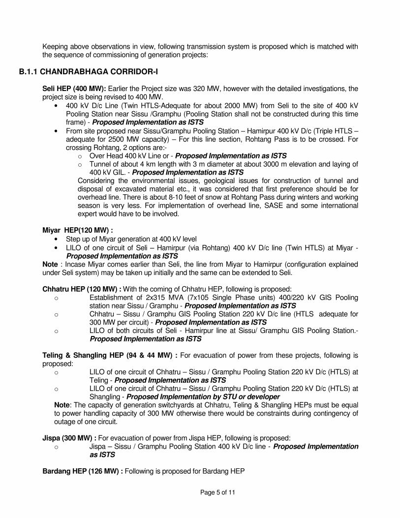
Keeping above observations in view, following transmission system is proposed which is matched with the sequence of commissioning of generation projects:
B.1.1 CHANDRABHAGA CORRIDOR-I Seli HEP (400 MW): Earlier the Project size was 320 MW, however with the detailed investigations, the project size is being revised to 400 MW.
• 400 kV D/c Line (Twin HTLS-Adequate for about 2000 MW) from Seli to the site of 400 kV Pooling Station near Sissu /Gramphu (Pooling Station shall not be constructed during this time frame) - Proposed Implementation as ISTS
• From site proposed near Sissu/Gramphu Pooling Station – Hamirpur 400 kV D/c (Triple HTLS – adequate for 2500 MW capacity) – For this line section, Rohtang Pass is to be crossed. For crossing Rohtang, 2 options are:-
o Over Head 400 kV Line or - Proposed Implementation as ISTS o Tunnel of about 4 km length with 3 m diameter at about 3000 m elevation and laying of
400 kV GIL. - Proposed Implementation as ISTS Considering the environmental issues, geological issues for construction of tunnel and disposal of excavated material etc., it was considered that first preference should be for overhead line. There is about 8-10 feet of snow at Rohtang Pass during winters and working season is very less. For implementation of overhead line, SASE and some international expert would have to be involved.
Miyar HEP(120 MW) :
• Step up of Miyar generation at 400 kV level
• LILO of one circuit of Seli – Hamirpur (via Rohtang) 400 kV D/c line (Twin HTLS) at Miyar - Proposed Implementation as ISTS
Note : Incase Miyar comes earlier than Seli, the line from Miyar to Hamirpur (configuration explained under Seli system) may be taken up initially and the same can be extended to Seli. Chhatru HEP (120 MW) : With the coming of Chhatru HEP, following is proposed:
o Establishment of 2x315 MVA (7x10⁵ Single Phase units) 400/220 kV GIS Pooling station near Sissu / Gramphu - Proposed Implementation as ISTS
o Chhatru – Sissu / Gramphu GIS Pooling Station 220 kV D/c line (HTLS adequate for 300 MW per circuit) - Proposed Implementation as ISTS
o LILO of both circuits of Seli - Hamirpur line at Sissu/ Gramphu GIS Pooling Station.- Proposed Implementation as ISTS
Teling & Shangling HEP (94 & 44 MW) : For evacuation of power from these projects, following is proposed:
o LILO of one circuit of Chhatru – Sissu / Gramphu Pooling Station 220 kV D/c (HTLS) at Teling - Proposed Implementation as ISTS
o LILO of one circuit of Chhatru – Sissu / Gramphu Pooling Station 220 kV D/c (HTLS) at Shangling - Proposed Implementation by STU or developer
Note: The capacity of generation switchyards at Chhatru, Teling & Shangling HEPs must be equal to power handling capacity of 300 MW otherwise there would be constraints during contingency of outage of one circuit.
Jispa (300 MW) : For evacuation of power from Jispa HEP, following is proposed: o Jispa – Sissu / Gramphu Pooling Station 400 kV D/c line - Proposed Implementation
as ISTS
Bardang HEP (126 MW) : Following is proposed for Bardang HEP

Page 6 of 11
o Step up at 400 kV o LILO of one circuit of Seli – Sissu / Gramphu Pooling Station 400 kV D/c (Twin HTLS) -
Proposed Implementation as ISTS
Rasil HEP (130 MW) o Step up at 400 kV o LILO of one circuit of Seli – Sissu / Gramphu Pooling Station 400 kV D/c (Twin HTLS) -
Proposed Implementation as ISTS Tandi HEP (104 MW)
o Step up at 400 kV o LILO of one circuit of Seli – Sissu / Gramphu Pooling Station 400 kV D/c (Twin HTLS) -
Proposed Implementation as ISTS
Pattam HEP (60 MW) : o Step up at 220 kV o Pattam – Miyar 220 kV D/c - Proposed Implementation as ISTS o Provision of 1x250 MVA(4 nos. of 83.3MVA Single Phase units), 220/400 kV GIS
Pooling Station at Miyar. Incase of space constraints at Miyar switchyard, a separate pooling station would be required.- Proposed Implementation as ISTS
Tignet HEP (81 MW)
o Step up at 220 kV o LILO of one circuit of Pattam – Miyar 220 kV D/c - Proposed Implementation as ISTS
For Pattam & Tignet HEP transmission systems, it is assumed that Pattam would be coming up prior to Tignet. In case Tignet HEP materializes before Pattam, 220 kV D/c line and provision of ICTs shall have to be matched with Tignet HEP. NOTE: (Additional system beyond Hamirpur would be planned based on the requirement / commissioning of new projects.) - Proposed Implementation as ISTS
B.2.2 CHANDRABHAGA CORRIDOR-II It is proposed that the generation projects in the downstream of Seli HEP i.e. Reoli Dugli (420 MW), Sach Khas (149 MW), Purthi (300 MW) and Duggar (236 MW) may be evacuated through Jammu region as these projects are close to that region, there are severe R-o-W constraints from Seli to Reoli Dugli and it may not be feasible / reliable to evacuate full 3850 MW through single corridor. Reoli Dugli HEP (420 MW) & Sach Khas (149 MW): Both these projects are allocated to L&T and investigations for preparation of DPR are in progress. As per preliminary discussions, these projects are expected to come up by 2018. Following transmission scheme is proposed for evacuation of power from these projects:
o Generation step up at 400 kV level (for both projects) o Reoli Dugli– Kishtwar 400 kV D/c (Twin HTLS-Adequate for 1500 MW) - Proposed
Implementation as ISTS o Establishment of 400 kV switching station at Kishtwar - Proposed Implementation as
ISTS o LILO of Dulhasti / Ratle – Kishenpur 400 D/c (Quad) line at Kishtwar - Proposed
Implementation as ISTS

Page 7 of 11
o LILO of one circuit of Reoli – Kishtwar at Sach Khas - Proposed Implementation as ISTS
o Generating Switchyard capacity to be kept for 1500 MW at each Power House.
Purthi HEP (300 MW) : Following transmission system is proposed with Purthi HEP
o Generation step up at 400 kV level o LILO of one circuit of Reoli – Kishtwar 400 kV D/c at Generating station - Proposed
Implementation as ISTS o Generating Switchyard capacity to be kept for 1500 MW at Power House.
Duggar HEP (236 MW) : Following is proposed for transfer of power from Duggar
o Generation step up at 400 kV level o LILO of one circuit of Reoli – Kishtwar 400 kV D/c at Generating station - Proposed
Implementation as ISTS o Generating Switchyard capacity to be kept for 1500 MW at Power House.
Note: 1) Initially some margins may be available beyond Kishtwar, however system strengthening would be required depending on the generation addition. - Proposed Implementation as ISTS 2) Feasibility of the option of taking a line to Kishtwar, needs to be ascertained as Task Force visited only upto the State border of Himachal Pradesh.
C. BEAS BASIN
Further there were certain issues for evacuation of power for Beas Basin, these issues were also discussed and analysed. A brief summary of those issues is given below: Task force visited 400 kV switching station (under construction) at Banala. Corridor constraints for additional 400 kV lines were discussed and it was observed that it may not be possible to bring additional new 400 kV lines at Banala Pooling Station. POWERGRID informed that there is a proposal from Everest Power Private Limited(EPPL) to delink their Malana-II HEP (100 MW) from 220 kV D/c line of AD Hydro. Once approved, Malana-II shall be delinked and connected with Banala Pooling Station through 220 kV D/c Line. The proposal to delink Malana-II from AD Hydro 220kV D/c line is subject to approval of Standing Committee and the consent of the Malana-II HEP developer. HPPTCL proposed that the capacity available in the 220 kV line of AD Hydro shall be utilized by HPPTCL to evacuate 100 MW of Small Hydel potential by LILO of 220 kV AD Hydro Line at Fozal. It was opined by CEA and POWERGRID that this is a dedicated line of AD Hydro, however, if desired, HPPTCL may take up the matter directly with AD Hydro. HPPTCL proposed that 45 MW of Small Hydel potential upstream of Malana-II shall be evacuated through independent 220 kV Chhaur - Banala line. It was informed by CEA and POWERGRID that the line would be a dedicated line of Malana-II, however HPPTCL may take up the matter directly with EPPL. HPPTCL requested for two nos. of 220 kV bays at Banala Pooling Station. POWERGRID informed that there is space for four nos. of 220 kV bays at Banala out of which two can be utilized for Malana-II and balance two, be utilized for HPPTCL. Nakhtan HEP (520 MW) – Nakhtan HEP is located in the upstream of Parbati-II (earlier it was identified as Parbati-I with a capacity of 750 MW. Due to environmental issues, the project capacity has been

Page 8 of 11
revised to 520 MW and named as Nakhtan). Regarding evacuation of power from Nakhtan HEP, some new Pooling Station in the vicinity of Parbati-II or Parbati-III or Parbati Pooling Station would have to be developed and system would be integrated with Parbati/Koldam system. While finalizing the scheme, the constraint in switchyard capacity of Parbati/Koldam HEP is to be taken into account.
D. ISSUES / CHALLENGES TO BE ADRESSED:
1. Generation Switchyard Capacity: As most of generations shall be connected through LILO of high capacity common corridors, therefore the generation switchyard should have capacity equivalent to the capacity of the line and generation switchyard should not become a bottleneck for utilization of line.
2. Switchyard capacity of Pooling Stations: The major Pooling Stations are proposed at
Wangtoo, Jangi, Ka Dogri and Sissu / Gramphu. The switchgear & bus rating of the pooling stations should be equivalent to 3150 / 4000 Amps depending upon the power handling requirement.
3. Challenges / Issues in Implementation: For evacuation of power from above basins, the lines
would have to traverse through high altitude, tough mountainous terrain, snow bound areas, glacier prone areas etc. Broadly, following issues would have to be considered:
a. Tough / Snow Bound terrain : Due to Tough / Snow Bound terrain, special design would required.
b. Short Working Season: Due to high snow during winters, the working season in these areas is very less i.e. about 5-6 months in a year. Further, these areas generally remain cut off from mainland during heavy snow period. Considering these factors, the total period required for construction would increase substantially. It would also be very difficult to firm up the exact time frame for the transmission project.
c. Avalanche / Glacier prone area: Most of the area in Lahaul / Spiti valley is glacier / avalanche prone. Hence, for tower spotting, help from SASE, Ministry of Defence and local population would be required. Avalanche protection measure would also be required.
d. Design of transmission line: At Rohtang Pass, there is a snow of about 8-10 feet and there are high speed winds. In addition, lines would be traversing through very high altitude and snow bound regions. For design of transmission lines, especially for crossing Rohtang Pass, services of some international consultant might be required.
e. Environmental Issues: In some areas there is lot of forest involvement. Advance action for addressing environmental issues should be taken up.
f. Land Acquisition: Land acquisition process may be initiated after site selection of location of various Pooling Stations.
g. Transportation Problems: Most of the roads are ‘Kutcha’ roads and there are many bridges with a maximum load bearing capacity of 9 tonnes. While implementation, this may create a bottleneck. This issue needs to be analyzed in advance.
h. Estimation of Cost of Project: Due to the uncertainties & challenges involved, the cost estimation of the project would be very difficult.
4. HTLS Conductor Selection: Most of the lines are proposed with HTLS conductor to keep the
weight of tower to the minimum and to have maximum power transfer capacity. The conductor would also be facing ice loading and heavy winds. Conductor selection is to be carried out with extra care. Further to avoid high MVAR loss and to restrict transmission losses under contingency conditions, it is proposed to select the conductor considering maximum conductor temperature as 130° C.
Page 9 of 11
5. High Initial Cost: The generators would be coming up in a phased manner. The cost of the transmission system would be very high, as it has to keep the margins for future capacity addition. Here, it is also to be mentioned that applications for transmission access for most of the projects have not been received.
6. Difficult assessment of civil works: In many areas, there are loose rocks and almost vertical
mountains. A lot of benching and revetment would be required. In many areas avalanche protection measures would also be required. Considering these aspects, it would be very difficult to assess the exact quantities of civil works for lines.
7. LILO of Alternate circuits for balanced loading: Evacuation of many of the generation
projects is proposed through LILO of one circuit of high capacity common corridor line at the generation projects. It would be preferable that LILO of alternate circuit is carried out to have balanced loadings on both the circuits to the possible extent.
8. Other Issues:
• The generation plant size varies from as low as about 40 MW to as high as about 650 MW. However, due to tough terrain only one / two high capacity transmission corridors can be constructed. There would be a wide variation in the commissioning schedule of the generation projects.
• Long term open access applications for most of the projects have not been received, however as per the load generation scenario of Himachal Pradesh most of the power generated from these projects would have to be transmitted out of the state. The transmission systems need to be developed as ISTS system.
• The transmission system of the generation projects, which are proposed to be connected through LILO of high capacity corridor or through shared corridor, should be implemented as ISTS system as the transmission line would be having a specialized design and use new technologies. This is also required considering that a large amount of generation would be transferred through corridor and the reliability of the corridor would be very important.
• System strengthening beyond the proposed pooling points shall be identified as per the power transfer requirement.

Page 10 of 11
EXHIBIT-I
JANGI
KILLING - LARA
MANE-NADANGLARA - SUMTE
SUMTE - KHATANG
CHANGO - YANGTHANG
YANGTHANG - KHAB ROPA
KHABTIDONG-I
KASHANG-I,II,II & IV
BOGTU S/S
SHONGTONG - KARCHAM
KARCHAM-WANGTOO
KOTLA
NATHPA
RAMPUR
LUHRI
NALAGARH TO ABDULLAPUR
700 MW
TO KUNIHAR
432 MW
JHAKRI1500 MW S/S
BASPA-II
40 MW
70 MW104 MW
140 MW
130 MW
261 MW 60 MW
636 MW100 MW
(3x65 + 48 MW)
450 MW
SORANG100 MW
JHANGI THOPAN & THOPAN POWARI(480 + 480 MW)
300 MW
1000 MW
BHAVA120 MW
LEGEND
Master Plan of Evacuation System
TO MOHALI
for Projects in Satluj Basin
400/220 kV PS
KA DOGRI
TO PATIALA/KAITHAL/HISAR
220 kV ( EXISTING/ U.C.)
220 kV LINE
400 kV QUAD COND.
400 kV QUAD COND. (HTLS)
Existing Proposed
400 kV TRIPLE SNOWBIRD COND.
LARA 60 MW
TIDONG-II90 MW
400/220 kV
(HTL
S L
INE)
18 Km
20 K
m
4 Km
18 Km
HARYANA/PUNJAB
WANGTOOPLG. STN.
50 K
m
QU
AD
H
TLS
(TWIN MOOSE)
(TRIPLE
SNOWBIRD)
(TW
IN M
OO
SE
)(T
WIN
MO
OSE)
(SIN
GLE HTLS)
(QUAD)
(TRIPLE
SNOWBIRD)
(TRIPLE
SNOWBIRD)

Page 11 of 11
EXHIBIT-II
DUGAR
SACH KHAS
SELI
REOLI DUGLI
BARDANG
RASILTANDI
TELLING
PATTAM
JISPA
CHATTRUPOOLING STN.
JAMMU(DODA)
(360 MW)
(149 MW)
(400 MW)
(81 MW)
(60 MW)
(420 MW)
(141 MW)
(150 MW)(150 MW)
(300 MW)
(94 MW)
(140 MW)
R I V E R CHANDRA BHAGA
220 kV
POWER EVACUATION ARRANGEMENT FROM CHANDRABHAGA BASIN IN HP
RIVER CHENAB
(LAHAUL & SPITI)
TRIPLE HTLS (400 KV)
TWIN MOOSE (400 KV)
SISSU
(TRIPLE HTLS)
(TWIN HTLS)
MIYAR(90 MW)
SHALING(44MW)
TIGNET
(TWIN HTLS)
PURTHI(300 MW)
TO KISHTWAR
HAMIRPUR
(HTLS LINE)
(TWIN MOOSE)
TWIN HTLS (400kV)
(HTLS LINE)
220 kV HTLS