Embed Size (px)
Citation preview

www.aeraweb.org
Mark Lehner, Mohsen Kamel, and Ana Tavares
with contributions by Glen Dash, Yukinori Kawae, Freya Sadarangani, James Taylor,Judith Bunbury, Catherine Lutley, and Angus Graham
Ancient Egypt Research Associates, Inc.
Giza Occasional Papers 3
Giza Plateau Mapping ProjectSeasons 2006–2007Preliminary Report

www.aeraweb.org
Giza Occasional Papers 3 3
www.aeraweb.org
© 2009 by Ancient Egypt Research Associates Layout by Alexandra Witsell, Wilma Wetterstrom, and Amanda Pavlick
Printed in Hollis, NH, by Puritan Press.
All rights reserved. No part of this publication may be reproduced, stored in a retrieval system or transmitted in any form or by any means, electronic, mechanical, photocopying, recording, or otherwise without the prior consent of the publisher.
ISBN: 0-9779370-7-0
Published by Ancient Egypt Research Associates, Inc. 26 Lincoln Street, Suite 5, Boston, MA 02135 USA
Cover photo: Chaz Morse maps the pedestals in the Southern Magazine of the Pedestal Building (discussed on pages 65–78). View to the east. Photo by Mark Lehner.
Ancient Egypt Research Associates (AERA) is a 501(c) (3), tax-exempt, nonprofit organization dedicated to research on Ancient Egypt at the Giza Plateau.

www.aeraweb.org
Giza Occasional Papers 3 3
www.aeraweb.org
ContentsAcknowledgements 5
Introduction 6
Excavations
The Khentkawes Town (KKT) 7
North of the Wall of the Crow (WCN) 12
Wall of the Crow Northeast (WCNE) 17
WCES Burial Excavations 25
The Backhoe Trenches (BHT, BBHT1, BBHT2) 30
BBHT1 (Biggest Backhoe Trench) 32
Main Street East (MSE): Clues to the Pedestal Mystery 35
The Northwestern Bakeries of EOG 44
EOG/BHT 49
BB: The Royal Administrative Building (RAB) 59
Summary of BB Excavations, 2006 and 2007 61 by Freya Sadarangani
Area AA and The Pedestal Building 65
Area AA Preliminary Phasing 78 by James Taylor
House Unit 1 87 by Yukinori Kawae
References 92
Capital Zone Walk-About 2006: Spot Heights on the Third Millennium Landscape 97 by Mark Lehner
2006 Geophysical Season at Giza: A Ground-Penetrating Radar Study 152 by Glen Dash
Giza Geomorphological Report 158 by Judith Bunbury, Catherine Lutley, and Angus Graham
Giza Laser Scanning Project 166 by Yukinori Kawae
The 2006–2007 Team 176
Color Plates

4 Giza Plateau Mapping Project Seasons 2006–2007 Preliminar y Repor t
www.aeraweb.org
Giza Occasional Papers 3 5
www.aeraweb.org

4 Giza Plateau Mapping Project Seasons 2006–2007 Preliminar y Repor t
www.aeraweb.org
Giza Occasional Papers 3 5
www.aeraweb.org
Deep gratitude goes to all of our benefactors for supporting our excavations, field school, and other programs. For major support for our 2006–2007 field season we thank the Ann and Robert H. Lurie Foundation, the David H. Koch Founda-tion, the Charles Simonyi Fund for Arts and Sciences, the Peter Norton Family Foundation, the Waitt Family Foundation, the Myhrvold Family Charitable Foundation, and the Bill and Melinda Gates Foundation.
Our work would not have been possible without the additional support of Glen Dash, Ed and Kathy Fries, Rick and Kandy Holley, Jon Jerde, Marjorie Fisher, Ann Thompson, Bruce Ludwig, Alice Hyman, George Sherman, George Link, Nelson and Suzanne Del Rio, Michael Meyers and Judith Brown, Douglas Rawles, and Bonnie Sampsell. We also thank Robert Lowdermilk, James Allen, Keith Kerr, Michael K. MacDonald, Richard Redding, Carol Hancock, Stephen Sills, Matthew McCauley, Craig and Nancy Smith, Robin Young, David Goodman, George Bunn, Donna L. Dinardo, Don Kunz, Ray and Mary Arce, Ann Jaffin, Janice Brannon, Debby and Dan McGinn, Bonnie McClure, Michael and Janet Fourticq, Fred and Suzanne Rheinstein, Roddie and Steve Harris, Bill and Kathy Dahlman, Sandford and Betty Sigoloff, Dennis Pinion and Barbara Radd, Lora Lehner, Victor and Nancy Moss, Charles and Wanda Guttas, Richard Cook, Charles Rigano, and Ann Jaffin for their support.
Support for the Field School We thank Dr. Gerry Scott, Michael Jones, Shari Saunders, Mme. Amira Khatab, Janie Abd el-Aziz, and Lara Shawky for ARCE’s institutional support and financial sponsorship of the Field School through a USAID Egyptian Antiquities Conservation grant. We would like to thank Charles Simonyi and Susan Hutchison, Executive Director of the Charles Simonyi Fund for Arts and Sciences, for their support of AERA’s portion of the field school budget. We also thank Amsale Mengistu and Bill and Melinda Gates of the Bill and Melinda Gates Foundation for a grant to the 2007 Field School.
Our Egyptian and American ColleaguesFor very successful 2006 and 2007 seasons we are grateful to Dr. Zahi Hawass, Undersecretary of State and Secretary General of the Supreme Council of Antiquities (SCA). We thank Sabry Abd el-Aziz, General Director of Pharaonic Monuments; Kamal Waheed, General Director of Giza Pyramids; Ala El-Shahat, Director of Giza Pyramids; and Mohammed Shiha, Chief Inspector of Giza Pyramids. We thank Magdi El-Ghandour, Director of the Foreign Missions Department, and Shaaban Abd el-Gawad for their assistance. We thank Mohammed Hameida, Abeer Abdallah Bakri, Ashraf Abd el-Aziz, Hanan Mahmoud Soliman and Ahmed Eiz, for serving as SCA inspectors for the excavations, field school sessions, and work in the storeroom. Reis El-Sougheir did a remarkable job supervising our specialist workers and skilled excavators from Luxor.
We are grateful to Dr. Gil Stein, Director of the Oriental Institute, University of Chicago, and Dr. Larry Stager, Director of the Harvard Semitic Museum, for the support of their institutions. We also thank Dr. Joe Greene and Dr. James Armstrong of the Harvard Semitic Museum.
Acknowledgements

6 Giza Plateau Mapping Project Seasons 2006–2007 Preliminar y Repor t
www.aeraweb.org
Giza Occasional Papers 3 7
www.aeraweb.org
0
5
0
100
m
Khen
tkaw
es
Caus
eway
Men
kaur
e Va
lley
Tem
ple
Khen
tkaw
es M
asta
ba
Khen
tkaw
es To
wn
Hei
t el-G
hura
b si
te
Figu
re 1.
Map
of t
he K
hent
kaw
es To
wn
and
Mas
taba
and
the
Hei
t el-
Ghu
rab
site
. The
200
6–20
07 o
pera
tions
are
out
lined
.

6 Giza Plateau Mapping Project Seasons 2006–2007 Preliminar y Repor t
www.aeraweb.org
Giza Occasional Papers 3 7
www.aeraweb.org
Our work under the 2006–2007 concession from the Supreme Council of Antiquities took place during two
sustained periods: from September through December 2006, and from January to April 2007. During the first season, 2006, we conducted a session of the Giza Advanced Field School session for SCA inspectors from October 7 to December 15. During the second period, we conducted a session of the Giza Beginners Field School from February 10 to April 4, 2007.
Between September 2006 and June 2007 we excavated in eleven different areas (fig. 1), listed from north to south: the Khentkawes Town (KKT); North of the Wall of the Crow (WCN); Wall of the Crow Northeast (WCNE); West Dump (WD) and WCES burial excavations; the backhoe trenches (BHT, BBHT1, BBT:HH); Main Street East (MSE); Northwest Bakeries of EOG (BBHT2); East of Galleries
(EOG/BHT); the Royal Administrative Building (Area BB/RAB); the Pedestal Building and the adjacent areas north and east (Area AA); House Unit 1 and Pottery Mound in the Western Town (SFW, SFW.h1).
In addition to our excavations, between September 2006 and June 2007 we carried out the following proj-ects, listed in the order in which they took place: GIS (Geographic Information Systems), Giza-Saqqara Geomorphology Walk-About, Advanced Field School 2006 Session, Eastern Town House (ETH) Conservation, Geomorphology Survey, Geophysical Survey, Beginners Field School 2007 Session, X-ray Diffraction and X-ray Fluorescence Analysis, Giza Laser Scanning Survey (GLSS) of the Khentkawes monument, Archaeoastronomical Survey, and the Archaeological Science Program in our field laboratory.
ExcavationsWe report on our eleven 2006–2007 excavation areas
(fig. 1) from north to south.
The Khentkawes Town (KKT)Our geophysical survey in the area of the KKT took place in November 2006 (see page 152). Our Giza Laser Scanning of the Khentkawes Monument took place in December 2006. We worked in the Khentkawes Town (KKT) during our 2007 season, between late January and early April.
KKT Clearing, Mapping, and ErosionOur 2005 clearing and mapping took place mostly in the western side of the “foot” or southern extension of the KKT (Lehner, Kamel, and Tavares 2006: 11–16). We established that the western side of this part of the town was built upon a higher terrace of limestone quarry debris, and that the walls had eroded drastically in the 73 years since Selim Hassan’s 1932 excavation (Hassan 1943). In places the walls are missing completely, and in other places only the last centimeters or millimeters of the lowest course of mudbrick remain. The mudbrick walls on the lower terrace in the eastern part of the KKT foot appear better preserved, but we cleared only the tops of these walls.
In 2007 Lisa Yeomans cleared north and east in the leg of the KKT. Here Selim Hassan found the four east-ernmost buildings, which Yeomans designated G, H, I, and J, north of the causeway leading straight west to the en-trance to the Khentkawes monumental tomb (fig. 2). Our 2007 clearing also took in the northern ends of two build-ings (K and L) that lie south of the causeway. We cleared the tunnel under the causeway along the eastern side of an older street that ran between buildings I and J, and K and L respectively.
Altogether, Yeomans cleared, mapped with Pieter Collet, and assigned feature numbers over an area about 35 m north-south × 55 m east-west (fig. 2). “One of our purposes was to know more about the relationship be-tween the north-south and east-west aligned parts of the town” (Yeomans Weekly Report 07iii1).
We expected the mudbrick walls might be better pre-served here than where we cleared the western upper ter-race of the KKT foot in 2005. Unfortunately, the walls in this area were just as badly eroded, again, down to the low-est traces, or scoured away completely to expose underly-ing limestone bedrock or dumped quarry debris. Much of the thick northern enclosure wall, as well as the causeway walls, were completely gone. Some mudbrick traces on the bedrock, or cuts into the crushed stone and marl fill, still
Introduction

8 Giza Plateau Mapping Project Seasons 2006–2007 Preliminar y Repor t
www.aeraweb.org
Giza Occasional Papers 3 9
www.aeraweb.org
showed the tracks of walls. Enough remained to know which walls corresponded to those on Selim Hassan’s map and to get some idea of the stratigraphy and phasing (fig. 3).
Quarried Bedrock FoundationThe fact that many of the walls had been completely scoured away since Selim Hassan excavated allowed us to see the foundation of the town in the natural bedrock on the north of the area cleared in 2007.
The natural limestone of the Moqattam Formation at Giza is characterized by a sequence of harder layers in-terspersed by thinner and softer, more clayey layers. The 4th Dynasty quarrymen would take blocks comprising the harder layers by cutting the base along the softer layers, then prying the blocks up with large wooden levers in-serted into sockets cut into the softer layer.
The eastern end of the town (and probably the entire east-west length of the KKT “leg”) was founded upon a natural geological plane that the quarrymen left exposed as they removed stone along one of these softer, more marly beds. The original height of the bedrock rose up to 10 m above this plane, as shown by the stump of the Khentkawes Monument at the western end of the town, and the series of bedrock blocks isolated by the quar-rymen along the north side of the town. In the bedrock surface Yeomans documented numerous wedge-shaped cuttings in the bedrock surface, especially in the north-ern part of the 2007 cleared area. The rectangular cuttings often occur in groups of three. The bottoms slope down to a deeper end with a vertical edge. Found all over Giza,
these are the sockets for thick wooden levers to pry loose and maneuver blocks.
In the southern part of the cleared area, Yeomans found layers of crushed limestone and marl debris, which build up the western terrace of the KKT foot; “…since the quarry had left the bedrock sloping from north to south on a gradient following the natural strata of the lime-stone…large quantities of limestone and marl rubble from the earlier quarrying activity were used to build up the southern part providing a slightly more level area” on which to build the town (Yeomans 2007b: 13). In addition, the masons cut slightly into the bedrock on the north to create a more level foundation. However, the entire KKT still slopes considerably from west to east, and north to south following the dip of the bedrock layers.
Phases of the KKTYeomans summarized excavator Selim Hassan’s view of the KKT building history:
Selim Hassan divided the settlement of the Pyramid City of Khentkawes into three blocks according to the layout of the buildings. These were the larger ‘‘mansions’’ in the southeast, the second was a group of four smaller houses on the north reached by the underpass, the final group was the six larger buildings with a similar basic layout to the west near the monument of Khentkawes. Without stratigraphic excavation these groups were interpreted as different types of building and Hassan (1943: 36) believed that the “plan of the city shows that it was designed as a whole.” (Yeomans 2007b: 10–11)
Figure 2. Schematic plan of the Khentkawes Town showing the areas cleared and mapped during the 2007 season (after a drawing by Lisa Yeomans.)

8 Giza Plateau Mapping Project Seasons 2006–2007 Preliminar y Repor t
www.aeraweb.org
Giza Occasional Papers 3 9
www.aeraweb.org
The Prior Eastern BuildingsEven with the severely diminished remains of the walls, Yeomans detected in the stratigraphic relationships successive building phases of the KKT in this area.
One of the first indications was the western wall [27,912] of Building I, which is the second “house” from the east in the KKT leg. This wall has deteriorated into patches, but enough remained to see its north-south alignment and outer marl plaster line, which, on the southernmost patch [27,880], passes right under the southern wall of the cause-way leading to the Khentkawes monument (fig. 4).
This north-south wall also appears to continue further to the north [27,919] and since it has not eroded whereas the northern girdle wall [27,615] has completely eroded away in this area, it seems to indicate that the north-south large mudbrick wall was earlier than the northern girdle wall. (Yeomans Weekly Report 07iii15)
Yeomans came to the conclusion that the Buildings I, J on the north, and K and L on the south, all of which share the same width, were part of an early building phase, prior to the construction of the causeway that separated I and J on the north from K and L on the south, and prior to the buildings to the west along the northern side of the cause-way. In short, the foot of the KKT existed before the leg.
The recording and limited excavation has demonstrat-ed that the north-south part of the Khentkawes Town was earlier than the causeway and buildings that developed along the northern side of the causeway to the west. The eastern part of the town was also occupied longer with at least one phase of rebuilding (Yeomans 2007b: 26).
The Eastern EntranceWhen Yeomans cleared the entrance to the causeway she found further evidence of at least two major phases (fig. 5). The causeway, as in Selim Hassan’s published map, is only 1.51 m wide, leading straight west to the entrance into the Khentkawes Monument.
Projecting from the northern wall of the causeway (which forms the southern wall of Buildings I and J), the clearing exposed a large, fine limestone pivot socket, half-oval in shape, 52 cm wide and extending 50 cm into the causeway, 2 m west of the entrance through the eastern enclosure wall. This pivot socket, which is nearly identical to sockets belonging to chapels in the Djoser Step Pyramid complex at Saqqara, leaves only one meter-wide passage with the southern causeway wall marked by the line of marl plaster on its northern face. The socket is much too large for the width of the causeway.
However, 87 cm farther south than the southern causeway wall we exposed another marl line marking the
Figure 3. Remains of KKT walls (black) mapped in 2007, overlaid on Selim Hassan’s plan (hachured) of the KKT. Drawing by Lisa Yeomans.

10 Giza Plateau Mapping Project Seasons 2006–2007 Preliminar y Repor t
www.aeraweb.org
Giza Occasional Papers 3 11
www.aeraweb.org
26 27 28 29 30 31 32 33 34
G
F
E
D
C
B
H
Jamb
PivotSouth edge of causeway
Figure 4. Khentkawes Town composite map showing 2007 work. Drawing by Lisa Yeomans.
Figure 5. Remains of an eastern entrance doorway for an early phase building in the KKT. View to the northeast.
0 1 5 10 m
Mar
k Le
hner

10 Giza Plateau Mapping Project Seasons 2006–2007 Preliminar y Repor t
www.aeraweb.org
Giza Occasional Papers 3 11
www.aeraweb.org
plaster render on an earlier wall [28,985] that would have made a passage 2.38 m wide. This marl line juts north for a jamb that projects 21 cm on the east and 62 cm on the west. The jamb is located on an earlier southern wall im-mediately west of the socket on the northern causeway wall, and the two features belong to a wider doorway that preceded the causeway, which shows evidence of a door. The earlier door was monumental, leaving a passage of 2.26 m between the jamb and the northern wall, and 1.72 m between the jamb and the pivot socket.
North-South StreetA street, about 2 m wide, ran north-south between Buildings I and J and Buildings K and L. The eastern wall of Building I and the western wall Building K, 85 to 90 cm thick and lined with marl plaster on both sides, defined the sides of the street.
A doorway and threshold opened through the north-ern town enclosure wall into this street. The “street itself was cut into the bedrock and leads to the north” (Yeomans Weekly Report 07iii22). Alluvial mud fills the cut for at least 1.30 m north, which is as far as we cleared the street in our excavation this season. Yeomans noted a single course of stretcher bricks along the western side of the cut and that the alluvial fill contained pottery fragments and appeared to have been trampled.
Farther north, the street disappears into overbur-den filling the cemetery of rock-cut tombs of the eastern Central Field, which begin only several meters to the north of the entrance. The cemetery might have developed in the 5th Dynasty after the founding of the KKT, disturbing a pathway that was much longer. It is interesting that, over hundreds of meters to the north, the north-south street of the KKT approximately aligns with the bedrock bridge running along the western back of the Sphinx sanctuary, and with the street between the first and second rows of large mastabas from the west in the Eastern Cemetery, east of the Khufu Pyramid. Perhaps one continuous road existed along this axis.
Northern Entrance ThresholdSix limestone slabs laid into the bedrock cut of the street compose the threshold over a width of 2.10 m (4 cubits) east-west and 1.90 m north-south through the entrance in the north enclosure wall. The southeast corner slab is broken and weathered, but still shows the form of a pivot socket, 38 × 40 cm, for a swinging wooden door that shut against a jamb, probably also of wood, which is indicated by the emplacement molding on the western side of the threshold. The matching eastern jamb, which is also indicated on the threshold, reduced the width of the doorway to 1.17 m.
The limestone threshold now stands alone on the bed-rock because the northern mudbrick enclosure wall has completely eroded away on either side. We must work out the sequence of this threshold with the enclosure wall and the rest of this part of the KKT for there are indications that the north-south street is part of the early layout of Buildings I–J and K–L, and that the enclosure wall was built later. It could be the threshold originally opened between the northern walls of Buildings I–J, which the builders in-corporated into the later northern enclosure wall. Since the wall flanking the threshold has been entirely scoured away, we might never ascertain this point.
UnderpassAfter the inhabitants built the long east-west causeway between Buildings I–J on the north and K–L on the south, crossing and cutting off North-South street, they quarried out a tunnel or underpass that allowed passage from the eastern end of the KKT leg to the foot of the town.
About 5.90 m south of the entrance threshold through the northern enclosure wall, the quarrymen cut an under-pass into the far eastern side of the street, leaving beside it a dead space 1.10 m wide, blocked off by the causeway walls. The northern end of the tunnel opens 90 cm to 1 m wide for a length of 6.30 m (12 cubits). Thirteen steps, from 22 to 30 cm wide and 12 to 23 cm high, descend under a bedrock cover 48 to 58 cm thick and 5.90 m long. The un-derpass sinks 2.47 m at its deepest point. The quarrymen never finished the tunnel; they left the floor as a series of humps rising up to half a meter, which would have made any passage difficult. The underpass opens on the south as a trench 1 m (north end) to 92 cm (south end) wide for a length of 5.90 m. The floor of the southern end is a slope or ramp without steps.
It is…possible that the steps were intended in the ramp on the southern side in the finished structure, although the slope of the bedrock forms a shallower angle on the southern side and a ramp may have been sufficient for access through the underpass. The underpass was cut away from both sides leaving a slight misalignment where the mining activities met in the middle. (Yeomans 2007b: 20)
East of the KKTToward the end of the season, by late March, Yeomans had cleared the surface sand 5.70 m east of the east KKT enclosure wall. Initially we thought that this clearing answered the question of why the town turns 90° in an L-shaped ground plan.
The bedrock surface drops vertically immediately under the eastern side of the eastern enclosure wall. Our

12 Giza Plateau Mapping Project Seasons 2006–2007 Preliminar y Repor t
www.aeraweb.org
Giza Occasional Papers 3 13
www.aeraweb.org
clearing to the west revealed that the town is founded on a quarry plane that slopes from north to south, left when the 4th Dynasty Egyptians removed stone along one of the softer, marly geological beds. Just where they built the eastern enclosure wall of the town, they had quarried deeper, and the wall respected and runs exactly along the drop of the ledge to a lower level. We cleared the ledge for a distance of 19 m north to south.
At the far north end of our clearing, immediately east of the northeast corner of the town, the quarrymen left bedrock protruding like a wall or ramp, 2.10 m wide and extending 2.62 m (5 cubits) farther east than the eastern side of the enclosure wall and ledge. A mass of mud ex-tends farther east than this bedrock extension, sloping down underneath the sand. The bedrock and mud initial-ly looked like a ramp, and it is this feature that the geo-physical survey team detected with their radar survey (see below) during the fall of 2006.
The bedrock protrusion and mudbrick mass turned out to be an eastward extension of the KKT northern enclo-sure wall, 1.86 m wide between lines in the mass marking the marl plaster faces. About 4.5 m from the eastern face of the bedrock ledge and the eastern enclosure wall, these marl lines show the opening of a doorway, 74 cm wide, between jambs 52 to 62 cm wide. This would be another access from the north, like that marked by the threshold through the northern enclosure wall to the west. Moving through this second doorway from the north, one could turn right (west) through another doorway marked by a jamb, 1.60 m wide and protruding 0.70 m, built onto the south face of the north enclosure wall extension. Passing through this doorway, one entered a corridor, about 2.44 m wide, leading toward the face of the bedrock ledge. This was part of a corridor around the northern and western sides of a mudbrick building lying at a lower level than the KKT leg or foot.
Tumbled mudbrick fills the corridor, but the marl plaster lines show the northwestern corner of the lower- lying building, formed of walls about a meter thick. The plaster lines also show a doorway, 98 cm wide, through these walls at the far northern end of the western wall of this lower-lying building. The corridor between the build-ing and the bedrock ledge is a little more than 1.50 m wide, then narrows to about 1 m just before the KKT causeway opening because of steps lower on the face of the ledge. Tumbled mudbrick, sloping down to the east-southeast, also fills the interior of the building. Selim Hassan’s work-ers cut into the mudbrick fill of the lower-lying building, but did not excavate further.
This building, and the extension of the northern enclo-sure wall, do not show in Hassan’s published maps (1943);
nor do they show in the aerial Royal Air Force photograph from the Reisner archives (http://www.gizapyramids.org/code/emuseum.asp?newpage=giza1936zoomify), taken in 1936, four years after Hassan’s excavations. The area east of the KKT foot appears to have been covered with clean sand. Our exposure of these remains came in a trench through the sandy overburden 5.50 m wide (east of the ledge) and 14 m long north-south. Yeomans cleared another trench through the sandy overburden, 10.70 m farther south, and found a mudbrick north-south wall, more than 80 cm wide, with a marl plaster line on the western face. This wall creates a corridor, 1.4m wide, with the bedrock ledge. In our exposure, a tree root disturbed the eastern face of this wall, which is probably 1 m wide and a continuation of the western wall of the lower lying building that we exposed in the northern trench. If so, the lower mudbrick building extends more than 28 m north to south along the ledge.
Yeomans pointed out that the bedrock drop was not necessarily from any quarrying that preceded the KKT. “The cut and the [eastern] walls of Buildings L and J re-spect each other, but that does not necessarily indicate that the upper levels of the buildings were later than the cut” (Yeomans 2007b: 27). She points out that at its northern end, the ledge turns east where the bedrock protrusion is incorporated into the extension of the northern enclosure wall, as though the boundary wall already existed or was planned when the quarrymen cut the ledge. It is possible that the builders lowered the bedrock of the KKT for mak-ing the lower building. How this structure was articulated and functioned with the causeway up to the Khentkawes monument remains to be seen.
What is certain is that the KKT does not end where the leg turns to the foot on the east, and so is not in its en-tirety an L-shaped ground plan. The settlement continues farther east with mudbrick structures beyond the eastern end of the causeway.
North of the Wall of the Crow (WCN)In late 2004, a contractor used a mechanical digger to excavate a trench north of the Wall of the Crow for the foundation of a cement corridor from the town on the east to the modern cemetery at the base of the Gebel el-Qibli on the west. The contractor’s trench ran parallel to the Wall of the Crow, and 19 to 24 m north of it. The trench was 4.5 to 7 m wide, and 90.5 m long. A length of 64 m of this trench penetrated below the compact Old Kingdom surface we had exposed in early 2004 (Lehner 2009).

12 Giza Plateau Mapping Project Seasons 2006–2007 Preliminar y Repor t
www.aeraweb.org
Giza Occasional Papers 3 13
www.aeraweb.org
Major Stratigraphic FeaturesThe contractors trench (DDT) revealed that the compact Old Kingdom surface was the top of the higher of two layers of compact masons’ rubble, the Upper Rubble Layer and the Lower Rubble Layer, which sandwiched a sandy layer [22,882] between them (Lehner, Kamel, and Tavares 2006: 17–31). The Lower Rubble Layer features small hearths and pits with ash and pottery fragments. We speculated that these features mark the occupation of people who worked on building the foundation of the Wall of the Crow, which is about the same absolute level as the Lower Rubble Layer. We speculated that desert floods washing down the wadi between the Moqattam and Maadi Formations at Giza might have deposited the Sand Separation Layer and that this layer indicated an interruption in building the Wall of the Crow.
In 2005 Derek Watson (2005; Lehner, Kamel, and Tavares 2006: 21–24) excavated Trench 2, which ran south from the east-west contractor’s trench (DDT) to the Wall of the Crow (WCN operation shown in fig. 6 and fig. 7). The aim of Trench 2 was to trace the layering to the very base of the Wall of the Crow. We continued excavating toward this goal in 2006, again under Watson’s supervision.
Trench 2Trench 2 clipped the western end of “Masons’ Mound,” the remains of an ancient ramp or embankment against the eastern end of the northern side of the Wall. Masons’ Mound tails into the Upper Rubble Layer on the west. Or, to put it another way, the Upper Rubble Layer, some 40 cm thick at the juncture of Trench 2 with the contractor’s trench (DDT), expands eastward and southward into Masons’ Mound, which is some 2.25 m thick at the south end of the Trench 2 east (west-facing) section. This is just the tail end of Masons’ Mound, which rises farther east another 2 to 3 m.
During our 2006 season, Watson expanded Trench 2 to the west, and sunk a deep probe to the very base of the Wall of the Crow. Near the end of our 2006 excavation period, the situation in Trench 2 was as follows:
Trench 2 was about 2.80 m wide (the trench began 3 m wide at the top, the sides slope inward slightly for safety). For 10 m into the northern end of Trench 2, Watson’s ex-cavations exposed the surface of the Lower Rubble Layer [22,889]. The surface is characterized by large fragments of limestone in a marl-clay slurry, wet because of the wick-ing up of the ground water, which had risen so dramati-cally across our site.
The Sand Separation Layer that separates the Upper and Lower Rubble Layers is some 28 to 40 cm thick at the north end of the Trench 2 east section. The Sand Separation Layer thickens to 60 cm where Watson stopped excavat-ing this layer, leaving a sub-balk about 10 m southward
into Trench 2, about 7.25 m shy of the northern face of the Wall of the Crow. All these layers are thinner in the op-posite, west section of Trench 2 because of the slope and the thinning to the west.
The Sand Separation Layer includes several subsidiary lenses and layers, the results of separate events. A series of darker lines slope down to the south-southeast near the top of the Sand Separation Layer. In 2005 some team members thought these could be forset beds from spates of water flow. When they looked at the Sand Separation Layer cut by the contractor’s trench and Trench 2 in October 2006, the members of the geomorphology team, Judith Bunbury, Angus Graham, and Katy Lutley, charac-terized this as an
unusual sand deposit…While the lower portion of the sand is windblown, the upper part coarsens upwards and is thought to represent anthropogenic activity, perhaps the clearance of some windblown sand from another area and the incorporation of successively more [mud] brick and stone. (Bunbury, Lutley, and Graham, this volume)
After our 2006 season it seemed more likely that the darker lines are “tip lines” from people dumping the sandy material. It seems most likely that people dumped the higher part of the Sand Separation Layer as a bed for the Upper Rubble Layer and the Masons’ Mound ramp or embankment.
West Extension of Trench 2In 2006 Watson first extended Trench 2 to the west, opening a square 6 m east-west × 5.60 m north-south. The south side of his extended excavation exposed more of the northern face of the Wall of the Crow.
In this extension, through much of November, Watson excavated a series of limestone rubble walls, some ren-dered in marl plaster, some running parallel to the Wall of the Crow, others perpendicular to these, forming com-partments, including triangular spaces. These structures are a crude version of the retaining and accretion walls, such as the Egyptian builders used for making temporary ramps and embankments for building large-stone struc-tures. We have several examples at Giza. The evidence sug-gests, again, that Masons’ Mound is the remains of such a ramp or embankment. In his western extension, Watson further excavated through the lower western slope of this embankment.
When he had removed all these walls and fill, Watson was on the surface equivalent to the top of the Sand Separation Layer—the sandy horizon that separated the Upper and Lower Rubble layers farther north in Trench 2 and in the contractor’s trench (DDT). He was still 90 cm above the base of the Wall of the Crow.

14 Giza Plateau Mapping Project Seasons 2006–2007 Preliminar y Repor t
www.aeraweb.org
Giza Occasional Papers 3 15
www.aeraweb.org
House Unit 1
Area AA &Pedestal Building
Pedestal BuildingNorthern Building
Bakery Complex
RAB
EOG/BHT
WCNEWCN
Enclosure Wall
BBHT1
MSE
Eastern Town House
DDT
Main Street
Western Roadway
Figure 6. Map of the Heit el-Ghurab site showing the 2006–2007 operations.
WCNEWCN
Area AA and the Pedestal Building
House Unit 1
LNE

14 Giza Plateau Mapping Project Seasons 2006–2007 Preliminar y Repor t
www.aeraweb.org
Giza Occasional Papers 3 15
www.aeraweb.org
Watson’s Probe and Connector TrenchesWithin his western extender trench, Watson excavated a deeper probe down to the surface of the Lower Rubble Layer and south to the foundation of the Wall of the Crow. In 2005 he had excavated down to the surface of the Lower Rubble Layer in the northern 10 m of Trench 2. But he left the Sand Separation Layer unexcavated in the 4 m between that deeper excavation and the deeper probe in his western extender trench. In order to trace the stratification of the Lower Rubble Layer and the Sand Separation Layer between the two deeper excavations, Watson excavated a connection.
Probe Trench to the Base of the Wall of the CrowFor his probe, Watson stepped out 2 m into his extension trench from the east section of Trench 2. His probe was thus up against the Wall of the Crow, about in the middle of the 2006 extension. His probe trench was 2 m wide × 3.5 m north-south perpendicular to the base of the Wall of the Crow.
Connector TrenchThe connector trench had to be narrow, due to time and safety reasons. By now a huge amount of indurated sand
comprising Masons’ Mound had collapsed from the eastern section of Trench 2. The connector trench was 1.20 to 1.25 m wide, 4 m long, stepped in around 1 m from the eastern section of Trench 2, and stepped in about 60 to 70 cm from the western section. The southern end of the connector trench opened, 60 cm wide, to the northeast corner of the probe trench. This gave a westward jog, about 20 cm, to the sections through the Sand Separation Layers left by the two trenches. The depth of the connector trench was about 40 cm down to the surface of the Lower Rubble Layer.
Layers to the Bottom of the Wall of the CrowThe top of the Lower Rubble Layer [25,745], which is so distinct with its concentrated, yellowish marl-clay matrix, rises and sinks in humps and depressions. In 2005 we thought that depressions showing in this layer in the sections of the DDT trench might be channels cut by streams of water flowing from the wadi. In the surface of the Lower Rubble Layer exposed in Trench 2, the western extender, and in the connector trench, the depressions appear less like erosion channels and more like pits left by people.
Connector Trench
Probe
Figure 7. Map of the WCN operations.

16 Giza Plateau Mapping Project Seasons 2006–2007 Preliminar y Repor t
www.aeraweb.org
Giza Occasional Papers 3 17
www.aeraweb.org
End of the Sand Separation LayerIn Trench 2, south toward the Wall of the Crow, the Sand Separation Layer turns chocolate-brown with alluvial mud clumps [25,734]. This layer is 18 to 20 cm thick above the Lower Rubble Layer. Once Watson excavated his connector, we could see that the darker sand with alluvial mud fragments pinches out only 35 m south of the southern sub-balk in Trench 2. This pinching out apparently marks the southern boundary of the Sand Separation Layer.
A layer of gritty, rubbly sand, 28 to 35 cm thick, covers the top of the Sand Separation Layer in the southern sub-balk of Trench 2 and continues to-ward the Wall of the Crow where it lies directly upon the Lower Rubble Layer. The gritty sand thins over the humps and fills depressions in the Lower Rubble Layer. It is very possible that people dumped this sand to level out the Lower Rubble Layer so as to make an even bed for the ramp or embankment of Masons’ Mound.
The gritty, rubbly sand continues around the jog of the connector trench to the probe trench. Here a finer brown sand [25,734] that contains a dark (ashy?) layer with pottery fragments caps the gritty sand layer and thickens to 45 cm at the southern end of the probe near the foundation of the Wall of the Crow.
Wall of the Crow FoundationAs they did with mastaba tombs and the Great Pyramid of Khufu, the builders prepared a low masonry foundation for the larger superstructure of the Wall of the Crow. In this case the foundation slabs range from 36 to 45 cm thick, and protrude from the bottom of the lowest course of stones by 35 to 40 cm. We found that the foundation similarly projected in the Deep Trench that we excavated in 1991 and 2001 on the south side of the Wall (Area WCS). Watson measured the top of the foundation slabs on the northern side as 15.91 m to 15.82 m above sea level (asl).
Here, in the WCN probe, we see that the builders laid the foundation blocks partially onto the Lower Rubble Layer, and partially into a shallow trench or cut into this layer, the surface of which is around 15.63 to 15.46 m asl. Watson measured the level of the cut for the foundation slabs at 15.41 to 15.29 m asl. This compares to the value, 15.41 m for the base of the foundation slab at the northeast corner of the Wall of the Crow.
In Yeoman’s probe (see below), the northeast corner block of the first course protrudes out beyond the founda-tion slab, while here, in Trench 2, the first course stones are set back, or, perhaps more probably, dressed back from
the edge of the foundation slabs, for it is a curious fact that the masons cut away the extra stock of stone and dressed flat the lower part of the northern face of the Wall of the Crow just where Watson excavated Trench 2 and the west-ern extension of that trench.
Lower Rubble Layer: Builders’ Working SurfaceTo reiterate, the builders laid the foundation slabs partially onto the Lower Rubble Layer, and partially into a shallow trench that they cut into this layer.
Watson’s trenches confirm what we had suspected in 2005 from the sections of the contractor’s trench (DDT) where we could see individual basket dump lines from the intentional preparation of the Lower Rubble Layer. The builders laid down the Lower Rubble Layer, with its con-
ExtensionProbe
Trench 2
Masons’ Mound
Contractors’ Trench (DDT)
Figure 8. WCN, Trench 2, the 2005 operation and the 2006 extension with deep probe on the left. In the background is the DDT and to the far right Masons’ Mound. At the bottom of the photo is the edge of the Wall of the Crow. Part of the east section of Trench 2 has collapsed. View to the north.
Mar
k Le
hner

16 Giza Plateau Mapping Project Seasons 2006–2007 Preliminar y Repor t
www.aeraweb.org
Giza Occasional Papers 3 17
www.aeraweb.org
centrated yellowish marl matrix and limestone rubble, as a good, hard bed on which they could bring in, maneuver, and set the stones for laying in the foundation and first course of the Wall of the Crow. The marl clay acted as a firm base, especially when mixed with crushed or frag-mented limestone (this is the composition of other ramps and embankments at Giza). When concentrated and wet, it also made for good lubrication for sliding blocks, either mounted on transport sledges or not. However, the un-evenness of the surface of the Lower Rubble Layer does not augur well as a plane for dragging in blocks. It re-mains possible that the depressions in the Lower Rubble Layer belong to channels cut by spates of water streaming through this side of the wadi mouth.
Summary of the Wall of the Crow StratigraphyThe primary goal of the excavation (DDT) in Trench 2, beginning in the Winter-Spring 2005 season, was to find the connection of the layers in the contractor’s trench to the base of the Wall of the Crow.
The Lower Rubble Layer From Watson’s probe against the base of the Wall of the Crow, we know that the workers prepared the Lower Rubble Layer before they laid in the foundation slabs. They laid down the Lower Rubble Layer as a working surface in the initial stage of building.
Gritty Sand Layer The next layer up is the gritty sand layer, 28 to 42 cm thick. This is quite distinct from the Lower Rubble Layer. The gritty sand lacks the marl matrix, but like that Lower Rubble Layer, on which the gritty sand rests, it has large limestone pieces. The gritty sand layer runs up to the lower face of the foundation slabs, so we know those slabs were already in place when the gritty sand layer was laid down.
The builders may have laid down the gritty sand layer as the base of a thicker bedding for the accretion walls and fill that comprise the structures of Masons’ Mound or earlier ramps and embankments. The gritty sand, with its limestone rubble, may have also been the working surface that the workers prepared for bringing in the larger blocks of the first course of the Wall of the Crow.
Finer Brown Sand LayerA finer, brown sand layer without limestone fragments covers the gritty sand layer. The finer brown sand layer is 43 to 45 cm thick, overlies the gritty sand and is quite distinct from it. After this brown sand accumulated for a thickness of about 24 cm, a thin layer, 12 cm thick, of dark soil with many pottery sherds was laid upon the brown sand.
The dark layer here ends about 2 m out from the Wall of the Crow. From here, tip lines—darker lines that show where people dumped individual baskets of sand—slope down to the face of the foundation slabs. They dumped the brown sand [25,734] to cover the dark pottery layer for another 13 cm. The brown sand banked up against and over the foundation slabs and against the bottom of the first course blocks. So the foundation and first course were already in place when people dumped this material as a bedding for the structures above that comprised the tail end of Masons’ Mound.
Connections to the Wall of the Crow, SummaryWatson’s sondage to the base of the Wall of the Crow makes it practically certain that the hearths, fireplaces, and mud-lined pits in the Lower Rubble Layer sectioned in 2005 by the contractor’s trench (DDT) are the campsites of the builders who worked on the colossal Wall of the Crow. Was there a hiatus in their work, evidenced by the depressions and channels? Did wadi floods make these cuts into the Lower Rubble Layer and deposit the Sand Separation Layer?
We think it probable that the builders had already laid the foundation platform and the first course when either natural forces or people dumping from baskets created the Sand Separation Layer between the Lower Rubble Layer and the Upper Rubble Layer. The Sand Separation Layer pinches out, and is covered by the more gritty and rubbly sand, and that layer is covered by finer brown sand.
All these sandier layers appear to us to intervene be-tween the Lower Rubble Layer, which precedes the foun-dation of the Wall of the Crow, and the Upper Rubble Layer, which thickens into Masons’ Mound. The inter-vening sandy layers could indeed represent a hiatus, since the lower part of this series appears to be windblown. But the upper part of the sandy sequence, with the subsidiary tip lines (rather than forset beds) and alluvial mud frag-ments, was most probably laid down and spread out by the builders as a make-up layer or bedding for the succes-sive accretions, retaining walls and infilling of the ramps and embankments, of which Masons’ Mound was the lat-est installment. They had already laid the foundation and first course when they prepared this sandy bed.
Wall of the Crow Northeast (WCNE)Our 2006 operations north of the eastern end of the Wall of the Crow (WCNE) began with a trench, 35 m long, that connects the eastern end of the 2005 contractor’s trench (DDT) to the 2002 trenches that extend 15 m north from the northern mudbrick wall [6300] of Gallery Set I, just in front of the east end of the Wall of the Crow (WCE) (figs. 9, 10).

18 Giza Plateau Mapping Project Seasons 2006–2007 Preliminar y Repor t
www.aeraweb.org
Giza Occasional Papers 3 19
www.aeraweb.org
Lisa Yeomans supervised our WCNE operation in 2006, before she went to the Khentkawes Town (see above) in 2007. Her combined trenches took the shape of a recti-linear letter “C,” open to the west, bottom to the north, top to the south. The connector trench between the 2005 contractor’s trench (DDT) forms the bottom of the C, and the 2002 trenches running north from the northern mud-brick wall [6300] of Gallery Set I are the back of the C. Yeomans excavated an extension westward along that mudbrick wall to the very northeast corner of the Wall of the Crow; this forms the top of the C.
Connection to the Sand Separation Layer in the Contractor’s TrenchTo reiterate, the 2005 contractor’s trench cut through two compact layers of masonry debris. The Lower Rubble Layer separates from the Upper Rubble Layer and begins to slope down to the east less than midway down the 64 m length of the contractor’s trench. The Upper Rubble Layer continues fairly level to the east until it expands into the round-topped Masons’ Mound banked against the far eastern end of the northern side of the Wall of the Crow. Because the Lower Rubble Layer slopes down toward the east, the sand layer that separates the two horizons thickens to the east.
We had hoped to track all these layers farther east by way of Yeomans’s connector trench from the eastern
end of the contractor’s trench all the way to the 2002 WCE northern trenches. Unfortunately, the Lower Rubble Layer is already diving into the alarmingly high water table be-fore the eastern end of the contractor’s trench. In fact, standing water filled the trench from just east of where Watson’s Trench 2 takes off perpendicularly toward the Wall of the Crow.
Farther westward in the connector trench, by the end of Yeomans’s 2006 excavations, one walked upon the sur-face of a dark layer [26,097] most of the way to the 2005 contractor’s trench (DDT). Because of the high water table, which formed a large pool in the contractor’s trench at the end of Trench 2, we could not trace the layers farther in this direction. But we suspected that the dark layer [26,097] is the same or equivalent to the darker layer, somewhat patchy, in the northern end of Trench 2, that shows at the top of the Sand Separation Layer between the Upper Rubble Layer and the Lower Rubble Layer in the 2005 trenches.
Again (see below, WCN) where the Sand Separation Layer thickens to the south in Trench 2, the dark layer be-comes patchier. Then it pinches out in Watson’s connector trench and deep probe to the very base of the Wall of the Crow. So we can now trace the layers from the eastern edge of Masons’ Mound (WCNE), along the northern edge of the Mound (DDT), and through the tail end of the Mound (Trench 2) to the very base of the Wall of the Crow.
WCNE
2002 Trench
Masons’ Mound
Trench 2
Connector Trench
DDT
Figure 9. General view of operation WCNE. View to the southwest.
Mar
k Le
hner

18 Giza Plateau Mapping Project Seasons 2006–2007 Preliminar y Repor t
www.aeraweb.org
Giza Occasional Papers 3 19
www.aeraweb.org
The WCE Cut and Granite DustYeomans examined a large cut [26,113] through the top of the northern wall [6300] of Gallery Set I. The cut begins 2.3 m from the inner corner formed by the northern [6300] and western [6278] walls of Gallery Set I. The cut extends for 2.60 m farther east, reducing the preserved height of the wall. The cut is rectilinear, with a flat bottom. Gray silty/sandy material with limestone fragments [26,113] filled the cut. Three courses of concentrated, black, untempered Nile alluvial bricks (UTA or “bubblegum bricks”) line the east side of the cut. Then the edge of the cut angles to the southeast as the upper edge of a pit, and the fill turns to granite dust, 40 cm deep within the area Yeomans examined. Yeomans believed people rather than natural forces created the cut and the fill.
Yeomans’s 2006 excavation here just clipped the west-ern edge of the massive cut and granite dust fill that was the focus of our excavations in 2001 and 2002 when we endeavored to find the buried eastern end of the Wall of the Crow (WCE) (Lehner 2002b: 52–53). A huge dump of granite waste begins from 2.6 to 5 m east of the eastern end of the Wall of the Crow. In our 2001 WCE trench we found the remains of mudbrick walls that frame galleries, with a low central bench or dividing wall characteristic of the other galleries in Sets II and III, and a rectangu-
lar fireplace, within a series of marl floors. These interior architectural features were preserved only 20 cm high at the bottom of the cut or depression, the edge of which merges with the cut that Yeomans examined in 2006 on the top of the northern wall of Gallery Set I. A tonnage of granite waste that people dumped into the pit covered the floors and features of the galleries. The granite dust must be waste from some massive amount of granite working nearby, possibly the casing on the Menkaure Pyramid or the granite lining of the chapel of the huge mastaba tomb of Queen Khentkawes, both works of the late 4th Dynasty.
In the 2.6 to 5 m between the cut and the end of the Wall of the Crow, Lauren Bruning excavated rooms, benches, floors, and walls of Gallery Set I that stood much higher than the gallery features at the bottom of the cut. Here the gallery ruins stood waist-high or better—albeit punctuated by many Late Period burial cuts. These walls apparently survived the great pit that people or natural forces cut through the galleries down to within 20 cm above the floors. They may have escaped the pit because they are much closer to the end of the Wall of the Crow. Stones from the end of the wall may have already slumped eastward 3 to 5 m when the great cut was made. The walls close to the end of the Wall escaped the deep cut because
Figure 10. Map of the WCNE operations.

20 Giza Plateau Mapping Project Seasons 2006–2007 Preliminar y Repor t
www.aeraweb.org
Giza Occasional Papers 3 21
www.aeraweb.org
they were underneath the stones that slipped from the wall.
In 2002 we hypothesized that water flowing eastward down the wadi and around the end of the Wall of the Crow made the cut through Gallery Complex I (Lehner 2002b: 52–53). However, this appears to us now to have been a sudden cut, not the result of gradual erosion after the occupants left these buildings derelict. Flowing water would not have left the built features, walls, and occupa-tional layers preserved 20 cm high off the floors and below the bottom of the cut. Also, our excavations and reexami-nation of the 2002 trenches to the north of Gallery Set I do not support the idea that water flowed up against the northern mudbrick wall [6300].
Again, the bottom of the cut [26,113] in the top of the northern gallery wall [6300] is very level, four brick cours-es up from the base of the wall. It is as though people made the cut by stripping bricks from the wall course by course. However, the southern edge of this cut begins to curve, and to look more like a natural pit, following roughly the southern face of mudbrick wall [6300]. It is possible that the removal of brick courses from the wall is a different “cut” than the major pit through the gallery ruins down to within 20 cm above the gallery floors.
The Curiously Angled Wall: An Old Diagonal Route?When she dug deeper in the northern end of the 2002 trench, Yeomans found a thin stone wall [26,130] running diagonally across the northeast corner where the 2002 trench turns slightly more than 90° west as the connector trench to the 2005 contractor’s trench. She exposed this thin stone wall for a length of 3 m. Sand accumulated along both sides of the little wall and eventually covered it for 20 cm on the northwest end, while a dark layer [26,097, see below] runs directly over the top of the wall on the southeast end.
The curious thing about this wall [26,130], composed of a single row of limestone pieces 30 cm wide, is that it runs at such a southeast-northwest angle, about 35° west of north, compared to all the other walls, which are, like practically all of the site architecture, turned just slightly west of north, so counter-clockwise (if north is 12 o’clock).
In 2001 we found another curious feature, similarly oriented southeast-northwest in the Deep Trench (see fig. 7) up against the southern side of the Wall of the Crow (WCS). Here, Paul Sharman excavated a thick layer of black alluvial mud and limestone rubble that the builders of the Wall of the Crow cut into for laying in the foundation slabs. Farther south in the WCS trench, the thick layer of alluvial mud included a smooth linear track that runs di-agonally across the trench from southeast to northwest.
The track is concave in cross-section, which gives it the appearance of a slipway. Mud slipways have been found in Nubia for dragging boats across the desert sand around a cataract (Vercoutter 1965: 68–69; 1970: 204–214). This linear feature was built onto a bed of marl and debris of large limestone pieces—possibly the same preparation as the Lower Rubble Layer on the north side of the Wall. The feature predates the Wall of the Crow, since the founda-tion trench for the wall cut through the mud layer.
Without a broader exposure, it is hard to understand the origin or purpose of these features south and north-east of the Wall respectively. They seem to hint at some route across the site from southeast to northwest, diago-nal to most of the architecture and pathways that we have so far mapped, which existed before the builders blocked the route by raising the Wall of the Crow.
Accretion Walls at the East End of Masons’ MoundWhile Yeomans excavated deeper in the connector trench (the bottom of the “C”), she also excavated right beside the northwestern corner of the mudbrick walls of Gallery Set I (the top and right end of the “C”).
We learned in 2002 that the ancient masons construct-ed the eastern end of the Wall of the Crow against the western mudbrick wall [6278] of Gallery Set I. Yeomans sank a new trench perpendicular to the northern mud-brick wall [6300] of Gallery Set I, just where it makes the northwest corner with the western wall [6278] of this block of galleries. Her trench extended north along the eastern base of Masons’ Mound.
Here she exposed a concentration of limestone pieces that appeared to form a fieldstone retaining wall [26,110] marking a formal, eastern boundary for Masons’ Mound, which is probably the remains of a construction ramp or embankment. Yeomans excavated 90 to 95 cm deep along the eastern face of this fieldstone wall [26,110]. Her trench extended 3 m north of the northwest corner of Gallery Set I (mudbrick walls [6278] and [6300]) and the northeast corner of the Wall of the Crow, to grid point 2.E5.
The fieldstone wall [26,110] appeared to retain the northeast corner of Masons’ Mound. The thickness of the fieldstone wall abutted slightly up against the northern face of the northern mudbrick gallery wall [6300]. The tops of the fieldstone and the mudbrick walls are flush.
The corners of Gallery Set I, the Wall of the Crow, and Masons’ Mound all meet here and would touch, ex-cept that the fieldstone wall separates the mudbrick wall [6278] and the Wall of the Crow. In fact, the fieldstone wall [26,110] runs into the seam between the large blocks form-ing the eastern end of the Wall of the Crow and the west-ern mudbrick wall [6278] of Gallery Set I. The builders placed the big, irregular limestone blocks that form the

20 Giza Plateau Mapping Project Seasons 2006–2007 Preliminar y Repor t
www.aeraweb.org
Giza Occasional Papers 3 21
www.aeraweb.org
eastern end of the Wall of the Crow right against the west-ern face of the older mudbrick wall [6278] on the south, but they angled the end of the Wall of the Crow slightly west of north to leave a thin pie-slice gap at the northern end of this contact between the mudbrick wall [6278] and the end of the Wall of the Crow. The fieldstone retaining wall [26,110] runs into the wide end of this gap, while its eastern edge abuts up against the north face of the older northern mudbrick wall [6300] of Gallery Set I.
Building Sequence: Ramp and Wall Rise TogetherBecause the fieldstone wall [26,110] abuts slightly against the northern face of the mudbrick wall [6300], it is certain that the occupants built the mudbrick corner of Gallery Set I (walls [6278] and [6300]) first, then the fieldstone wall [26,110] and the eastern end of the gigantic Wall of the Crow. The fieldstone wall [26,110] appeared to run farther north beyond the gap between the Wall of the Crow and the western mudbrick wall [6278]. It functions as an accretion or retaining wall that holds back the broken limestone fill of Masons’ Mound.
But how could the masons have built the fieldstone wall in that tight gap? We thought it possible that they built the fieldstone wall, which also retains the debris fill of Masons’ Mound, in tandem, or in sequence, with Masons’ Mound and in tandem with the successive courses of the Wall of the Crow. In other words, the wall composed of limestone pieces [26,110], Masons’ Mound, and the Wall of the Crow all belong to the same construction process.
This makes sense if Masons’ Mound is the remains of a ramp or embankment for moving stones up onto the course of stones under construction. The builders would have raised the large stones of the Wall of the Crow, course by course, dragging them up to the top of the ramp. Then they raised the ramp some more, by building more fieldstone walls to retain debris, to accrete and raise the embankment. Afterwards they brought in more stones, continuing the process. As Watson hypothesized from his excavations into the lower western slope of Masons’ Mound, the builders must have created a series of such ramps as they extended the Wall of the Crow (from west to east?).
Watson (2005: 119) pointed out that the top of Masons’ Mound is 3 m below the top of the Wall of the Crow, so the hypothetical ramp would not have delivered stones to the very top. Perhaps the workers removed the upper part of the ramp, perhaps the upper part eroded away, or per-haps workers delivered stones for the upper courses of the wall by means of other lateral ramps banked against the already-built parts of the Wall of the Crow.
By the middle of November, Yeomans had expanded her trench at the northeast corner of the Wall of the Crow
to the east, to join up with Lauren Bruning’s 2002 trench that ran 15 m north from the northern mudbrick wall [6300] of Gallery Set I. Her 2006 excavation thus included an extension to the east off the southern end of the 2002 trench (the top of the “C”). Her extension, within grid square 2.E6, measured 3.95 m east-west by 3.00 m north-south on the east and 3.56 m north-south on the west.
In this expansion, Yeomans picked up a second field-stone wall [26,122], about 70 cm to the east of the first. The second wall, 40 cm wide and preserved to a height of 54 cm, was built up against the face of the northern mudbrick wall [6300] of Gallery Set I and ran north while curving slightly to the east. Sandy soil with limestone chips filled the space between this fieldstone wall and the first [26,110]. The builders probably made this second wall to retain more material and extend Masons’ Mound to the east.
This second and later fieldstone retaining wall runs more than 18 m north where Yeomans picked it up in the connector trench between the eastern end of the 2005 contractor’s trench and the 2002 trenches.
Floors and Foundations in WCNEIn her trench, Yeomans excavated three or four floor levels north of the northern mudbrick wall [6300] of Gallery Set I and east of the eastern retaining wall [21,110] of Masons’ Mound. One of these floors [26,126] runs up against the base of the later, second fieldstone wall [26,122], which Yeomans removed in the course of her excavation. So that floor is later than the accretion wall [26,122].
Floors Northeast of the Wall of the CrowThe first, older fieldstone accretion wall [26,110] rests on a clay layer [26,109] in which a broad (2.20 m wide), shallow pit was cut [26,153], and filled [26,143] with many pottery sherds, mostly bread mold fragments. The clay layer [26,109] runs up against the northern mudbrick wall [6300] of Gallery Set I, and so the clay layer is later than that wall.
The marl plastering on the north face of the mudbrick wall [6300] stops 84 cm down from the preserved top, about 22 cm from the base of the wall. This level is com-mensurate with the floor level from the time of the plas-tering. This floor runs up to the face of the fieldstone wall, so it was laid down after that wall [21,110] was built.
Back (North) Doorway?These floors northeast of the eastern end of the Wall of the Crow show that people engaged in a fair degree of activity outside of Gallery Set I on the north, along the eastern base of Masons’ Mound. They must have moved in and out of the mudbrick complex via a door that Yeomans detected through the northern mudbrick wall [6300].

22 Giza Plateau Mapping Project Seasons 2006–2007 Preliminar y Repor t
www.aeraweb.org
Giza Occasional Papers 3 23
www.aeraweb.org
Immediately west of the cut [26,113] in the northern wall [6300] of Gallery Set I, Yeomans noted discontinui-ties in the brickwork, under the plaster of the northern face. These discontinuities might indicate a blocked door-way, some 80 cm wide, which once opened from the inte-rior of the gallery to the open area on the north.
Initially a doorway would have provided access to the area to the north of the gallery and this may have been contemporary to the accumulation of the bakery waste in [26,143]. This doorway was subsequently blocked-in, since the plaster physically extends behind an area constructed with a different brick type. The external surfaces then accumulated to the north of the gallery before the wall was replastered suggesting that the gallery was still in use throughout and therefore would still have been in use as the Wall of the Crow was under construction. (Yeomans Weekly Report 30xi06)
During the time that people used the floors that post-dated the blocking of the doorway, they may have reached the north exterior through similar doors in the as yet un-excavated parts of Gallery Set I farther east.
The Dark Horizon The surface of the clay layer [26,109] is a dark floor in phase with, or probably the same layer as, a salient dark layer [26,097] composed of clayey sand that slopes gently to the north from the intersection of the mudbrick wall [6300], the accretion wall [26,110] and the Wall of the Crow. The dark layer [26,097] thickens to the north in the 15-m length of the 2002 trench, and probably runs under Masons’ Mound.
In 2002 Lauren Bruning stopped her excavations at a higher floor [26,096], above the dark layer [26,097]. The higher “floor” [26,096] included a patch of alabaster dust [26,096]. Yeomans found more evidence of alabaster working in this higher layer to the north, just above the dark layer [26,097].
To reiterate, Yeomans’s 35-m-long connector trench between the northern end of the 2002 trench and the con-tractor’s trench (DDT) to the west, gave her excavation a large rectilinear “C”-shape, with the C open to the west. Turning the corner at the bottom (north) of the C, into the west-running connector trench, Yeomans could not, for lack of time and because of the high water table, excavate as deeply as we had hoped. Yeomans exposed the surface of the dark layer [26,097] in the north-facing southern section at the eastern end of the connector trench. Above it the alabaster dust layer [26,096] is 17 cm thick.
Sequence of Gallery Set I and Wall of the Crow: The Corner StoneBy the end of the second week in December 2006, our scheduled end of digging, Yeomans was left with a question that, even with all the time and effort we had put into Operation WCNE, we still needed to have confirmed: was the gigantic stone Wall of the Crow built after the mudbrick Gallery Complex I, as our 2002 results indicated (Lehner 2002b: 51–52)?
The accretion wall [26,110] and Masons’ Mound still masked the actual northeast corner of the Wall of the Crow. We believed that the accretion wall [26,110], which is an integral part of Masons’ Mound, and the Wall of the Crow rose incrementally together. In Yeomans’s extension trench, the accretion wall seemed to be founded on the same brownish sand layer [26,145] upon which the north-ern mudbrick wall [6300] of Gallery Set I was founded, which suggests the two walls and the Wall of the Crow were built at the same time—contrary to what we con-cluded from the results of our 2002 WCE operation.
Review of 2002 ResultsIn 2006 we saw that the accretion wall [26,110] along the eastern base of Masons’ Mound abutted the northeast corner of the Wall of the Crow and pressed against the eastern end of the great stone wall, running into the seam between it and the western mudbrick wall [6278] of Gallery Set I.
At the western end of a 2002 trench perpendicular to the eastern end of the Wall of the Crow, we widened a Late Period burial pit that cut through the western mudbrick wall [6278] of Gallery Set I to the very eastern end of the Wall of the Crow (Lehner 2002a: 51; 2002b: 52–53). In this trench we saw that the builders had plastered the western face of the mudbrick wall [6278] with marl before they built the huge stone wall up against it. Furthermore this plaster “lipped” down onto a floor that appeared to run westward in and under the eastern end of Wall of the Crow itself. In this trench, we also found a deeper mudbrick wall [6400], some 85 cm farther east than wall [6278], which appears to have been the western wall of Gallery Set I in an earlier period, founded at a lower level. The upper western wall [6278] is partially built over what remains of the lower western wall [6400]. So the 2002 results indicated that Gallery Set I was older than the Wall of the Crow, which was built up to it.
Slot through Masons’ Mound to the Northeast Crow Wall CornerWe decided we could not live with the unresolved question, or with any contradiction between our 2002 and

22 Giza Plateau Mapping Project Seasons 2006–2007 Preliminar y Repor t
www.aeraweb.org
Giza Occasional Papers 3 23
www.aeraweb.org
2006 stratigraphy. Therefore Yeomans excavated into the time devoted to data organization and report writing. She dug a slot, a small trench, 1.05 m wide, right through the accretion wall [26,110], penetrating 1.90 m westward into the eastern base of Masons’ Mound to expose the actual corner stone of the Wall of the Crow.
Right away Yeomans found that the accretion “wall” [26,110] is much thicker than the width of 76 cm where it fills the gap between the eastern end of the Wall of the Crow and the western wall [6278] of Gallery Set I. She wrote, “it is now clear that what was recorded as a north-south wall [26,110] is actually the end of a series of courses of limestone rubble that was carefully laid to ter-minate in a sloped elevation just beyond the junc-tion of the Wall of the Crow and Gallery Set I” (Yeomans Weekly Report 7xiii06).
The limestone rubble along the eastern slope of Masons’ Mound is more than 2 m thick to the west and at least 2 m high. Yeomans gave this fill new feature numbers, [26,155] to [26,157], but it is the same deposit as the accretion “wall” [26,110].
Corner StoneBy taking out this limestone fill, Yeomans exposed the northern face of a very large block that makes the northeast corner of the first regular course of the Wall of the Crow. This block stretches 1.60 m east to west, and rises 88 cm. The builders stepped back the next block up of the second course by about 52 cm (1 cubit) on the eastern end of the Wall (fig. 11).
Foundation TrenchAt the base of the corner stone Yeomans could see the telltale line between the brownish sand [26,145] on which the mudbrick gallery walls [6278] and [6300] rest and a darker sand [26,162]. The line was the upper edge of a trench that “cut” [26,163] down through the older layer [26,145]. The builders of the Wall of the Crow had cut into this sand to make a trench, into which they set a thinner foundation slab on which the larger corner stone rests. They filled the cut [26,163] with smaller stones and the darker sand [26,162].
The “accretion” [26,110]—actually, the total mass of limestone pieces [26,155] to [26,157]—sits on the older dark floor [26,109] that runs up against the mudbrick wall [6300]:
Below the rubble was a continuation of surface [26,109]; this was excavated as [26,158] in the sondage extension. At the eastern limit of the
Figure 11. Top: Junction of the Wall of the Crow, Gallery Set I northern and western walls, and Masons’ Mound. Figure 12. Above: Close-up of the base of the Wall of the Crow showing the foundation slab.
Mar
k Le
hner
Mar
k Le
hner

24 Giza Plateau Mapping Project Seasons 2006–2007 Preliminar y Repor t
www.aeraweb.org
Giza Occasional Papers 3 25
www.aeraweb.org
surface a posthole cutting the surface was excavated immediately to the east of the end of the rubble layers and this has been interpreted as remains of a post or perhaps an alignment to mark the end of the rubble structure during its construction. (Yeomans Weekly Report 14xii06)
As she removed the dark layer [26,109]=[26,158], Yeomans exposed the ashy, pottery rich layer of “bakery waste” [26,143]=[26,161] filling the shallow pit [26,153].
Foundation Slab and Elevation at Bottom
Below the pit [26,153], cut into the sand [26,145], a foundation cut for the Wall of the Crow was visible. Because of waterlogging, only the eastern end of the cut was excavated. This showed that the foundation stone laid into the cut was smaller in depth than the stones it supported. Also the second course of stone in the Wall of the Crow overhung the foundation stone to the north and east. The foundation cut [26,163] had been backfilled with limestone rubble packing fill [26,164] and an upper fill of mid-grayish brown sand [26,162]. (Yeomans Weekly Report 14xii06)
By excavating part of the fill of the foundation trench, Yeomans saw the foundation slab, which the builders had set down within the foundation trench that they cut through the older sand layer [26,145], upon which the mudbrick gallery walls rest (fig. 12). She was blocked from exposing much of the very bottom of the foundation course by the high water table, which pooled immediately in her small excavation.
We asked Yeomans if we could get down to the bottom of the foundation, as Watson had done in his deep probe (see pp. 17–18, this volume). Yeomans was able to widen her probe, taking out the dark sand [26,162] and limestone fill [26,164] for the 40 cm width of the foundation trench and 84 cm east to west.
She could now see that the foundation slab is 43–44 cm thick. The large cornerstone above it projected 20 or 30 cm farther out than the face of the foundation slab. This is the opposite of what Watson found in WCN (see above, pp. 17–18) where the foundation slabs project about 35–40 cm from the face of the first course above.
The builders set the foundation slabs down in the trench cut [26,163] so that the top of the slab was 25 cm lower than the surface on which the northern mudbrick gallery wall [6300] rests. Adding the 44 cm thickness of the foundation slab, the builders founded the bottom of the Wall of the Crow foundation some 69 cm lower than the base of the older mudbrick walls, [6300] and [6278], that form the northwest corner of Gallery Set I.
The elevation at the bottom of the Wall of the Crow foundation, as best Yeomans could determine down in the ground water, is 15.41 m asl. This is within centime-ters of the elevation of the bottom of the foundation that Watson found in his deep probe in the western extension off of Trench 2, 45 m to the west. It is also within centime-ters of the elevation at the base of the foundation that we found in the WCS deep trench in 1991 and 2001. The build-ers must have prepared a very level bed for laying out the foundation of the Wall of the Crow.
Tafla Packing in Seam and Foundation TrenchThe end of the large northeast corner block slopes up and back, and because the builders stepped the second course back by more than half a meter, they left a space, 74 cm wide, between the western mudbrick wall [6278] of Gallery I and the second course of stones of the end of the Wall of the Crow. They filled this space with the limestone pieces that we took as the accretion wall [26,110].
Toward the bottom of the second course block, the builders filled the narrowing space between the mudbrick wall [6278] and the large stone blocks with concentrated marl desert clay (tafla). They packed more marl clay into the cut through the sand layers [26,145] on which the mud-brick wall rests down to the very bottom of the first course block. Below this they filled the cut with the brown sand [26,162] and limestone fill [26,164].
Crucial Corner Between Wall of the Crow and the Gallery: SummaryLooking at the section that Yeomans left after removing the massive limestone accretion and fill in her cut through Masons’ Mound, we could appreciate how the Wall of the Crow was a gigantic, weighty mass that the builders parked up against the far northern end of the western wall [6278] of Gallery Set I. At the bottom of the juncture they placed the massive northeast corner block of the first course within 11 cm of the face of the preexisting mudbrick wall (they filled the top of the juncture with limestone fragments [26,110]).
Why? Why park this massive, gigantic stone struc-ture up against an already existing block of galleries, and thereby seal off the entire northwest access to the site, except for the gate, 2.62 m (5 cubits) wide, through the wall? Although the builders never finished it (they had yet to dress down most of the faces), the Wall of the Crow speaks of “permanence.” Those who ordered its construc-tion must have intended it to function for a very long time. That they parked the Wall of the Crow up to the far northwest corner of the Gallery Complex suggests they intended the Gallery Complex itself would be functioning permanently, or at least for a very long while.

24 Giza Plateau Mapping Project Seasons 2006–2007 Preliminar y Repor t
www.aeraweb.org
Giza Occasional Papers 3 25
www.aeraweb.org
Yet all our evidence shows that longevity was not the case for the Gallery Complex, or for this whole urban dis-trict. All our evidence points to the site being reorganized in a huge way during the reign of Khafre, builder of the second Giza pyramid, and occupied through the reign of Menkaure, who built the third Giza pyramid.
What force made that cut through Gallery Set I and why did people fill the cut with massive dumps of granite waste? Sometime after that people abandoned the settle-ment. We know from historical sources and other archae-ological data that at the end of the 4th Dynasty the royal house moved away from Giza. The pharaoh who followed Menkaure, Shepseskaf, built his monument at South Saqqara, 20 km away.
The reach for permanence was in vain. The builders left the Wall of the Crow unfinished with one of its con-struction ramps, Masons’ Mound, still in place along the eastern end of the northern side.
Very Deep Probe FrustratedAt the end of her excavations, Yeomans excavated a narrow trench, a “slot,” at the bottom of her westward extension off the 2002 trench, down into dirty sand below the foundations and floor levels mentioned above. Given the dramatic rise of the water table of a meter, there was no chance to probe deeper, as we did in 2001 in WCE.
There, some 10 m to the southeast, Jessica Kaiser sunk a small probe, about 1 m2 at the northern end of that sea-son’s north-south trench 14 m east of the end of the Wall of the Crow. She dug 1.5 m deeper than the level of a mud-brick wall of Gallery Set I through fairly clean sand with faint mud-tinted lenses and limestone flecks. At 14.88 m asl, the sand was damp and gravely, mottled with very dark brown clay and ash. It contained pottery fragments. The gravel component appeared to have pebbly stones such as we find in natural gravel in the high desert, so these could have been washed by wadi runoff from the higher desert. In the southwest corner of the pit large limestone rocks could be part of a fieldstone wall.
Reaching a depth of 14.88 m asl would have been pos-sible up to the end of our last season, in 2005, when the water table was around 14.75 m asl. As of the beginning of December 2006 it stood around 15.74 m asl, high enough to completely impede excavation.
WCES Burial ExcavationsMore than 1,500 years after the Old Kingdom pyramid builders abandoned the settlement south of the Heit el-Ghurab, it became a burial ground for people of low status. Students of the 2007 Beginners Field School excavated the burials of the 3rd Intermediate Period (1070–712 BC), Late
Period (712–332 BC), and Roman Period (30–395 AD). The following report is based on the osteologists’ end of season 2007 report (Björk and Pedersen 2007).
Jessica Kaiser, senior GPMP osteoarchaeologist, de-signed the osteoarchaeology course and syllabus. Affaf Wahba Abd El Salam Wahba, Ahmed Mohamed Gabr and Zeinab Sayed Hashish, all osteology graduates of the 2006 Advanced Field School, assisted Tove Björk and Kirsti Pedersen in supervising the osteoarchaeology teaching and burial excavations during the 2007 season. Sabry Hassan Hussein worked as an excavator and assis-tant draftsman, and Azab A. Hamid served as a survey assistant.
In addition to providing training for the Beginners Field School, the burial excavations served the wider purpose of 1) recovering ceramics that could help define the date of the burials, 2) providing a more detailed un-derstanding of the cemetery, and 3) adding to the corpus of systematically excavated human remains (Björk and Pedersen 2007: 25).
Location and Number of 2007 Burials ExcavatedWe designated the site of the 2007 burial excavations as Area WCES because the location is about 20 m south of the eastern end of the Wall of the Crow (figs. 13, 14). The work was a continuation of the osteologists’ excavations during the 2006 Advanced Field School. The 2007 excavations took place in grid squares 4.S–X.4, and later 4.U5. Within the area of the excavations, around 150 m2, the osteology team had surveyed the outlines of about 40 burial pits in 2005. With the additional square, 4.U5, the total burials pits counted in the 2005 survey number 50.
During the field school season 2007 we excavated 13 primary burials in the WCES area. At least six of the excavated burials this season had secondary individuals in them. One secondary [28,265] skull was excavated in the fill of Burial 441. Since there were no duplicates (i.e., bones that were already present in the primary burial) the skull must come from another disturbed burial in square 4.T4 that is not yet excavated … There were also secondary human bones [28,266] in the fill of Burial 437 that consisted of a root coming from a molar. The tooth came high up in the fill and could not come from the individual [28,306] lying much deeper, which was undisturbed. (Björk and Pedersen 2007)
Condition of the Skeletons and CoffinsLike the rest of the site, the burials suffered from the dramatically higher water table, even though the ruin surface immediately south of the Wall of the Crow is higher

26 Giza Plateau Mapping Project Seasons 2006–2007 Preliminar y Repor t
www.aeraweb.org
Giza Occasional Papers 3 27
www.aeraweb.org
Burial pits
2007 Excavations
Figure 14. Right: Burials in Area WCSE. The burial pits shown in black were excavated during the 2007 Field School. From Björk and Pedersen 2007, fig. 3.
Figure 13. Above: Map showing the area of 2007 burial excavations with burial pits mapped in 2005. Digitized by Johnny Karlsson.
0 25 50 m
0 1 5 m

26 Giza Plateau Mapping Project Seasons 2006–2007 Preliminar y Repor t
www.aeraweb.org
Giza Occasional Papers 3 27
www.aeraweb.org
ground than the Gallery Complex to the east. However, the burials in Area WCES are not as high as those that the 2005 Beginners Field School excavated in Area WD on the slope of the escarpment farther west and south.
In general the burials from the WCES area are in a poorer state of preservation than burials excavated elsewhere on the site, primarily due to the lower elevation. The burials in the WCES area had an average bottom elevation of 16.5 m above sea level (asl) compared to the 19.19 m asl in the WD area. The dampness also affected the colouring of the bones. The skeletons in the WCES area are darker than those from higher levels and less resistant to even mild handling.
Five burials, or 38.5% out of the 13 excavated burials this season, had coffins, and only one of them, Burial 442.2 belonged to a child. All coffins had remains of colors left on them. Usually the decoration varies a lot, however this season’s coffin decorations consisted of vertical or/and horizontal lines. No inscriptions were to be found. The shape, all anthropoid, could be determined for four of the coffins. (Björk and Pedersen 2007: 23)
Age and Sex of SkeletonsThe team excavated skeletons of children, juveniles, and adults during 2007 (table 1).
Two individuals [28,306] in Burial 437 and an individual [28,305] in Burial 450 were too poorly
preserved for making a sex assessment. Four individuals [28,264] in Burial 439, [28,289] in Burial 441, [28,281] in Burial 442.2 and [28,326] in Burial 451 were too young to make a sex assessment. Of the remaining seven individuals two were estimated female, one possible female, two males and two possible males. This gives us a sex ratio of 60:40. However the WCES sample is at this point too small to draw any larger conclusions. This demands a larger analyzed material for comparison. (Björk and Pedersen 2007: 20)
As we have seen in previous groups of burials, the most adorned skeleton is that of a child, in this case Burial 439, a child 3 to 4 years old. Cowry shells from bracelets clustered around the wrist. A scarab that lay within the left ribs was probably placed close to the heart. None of the other skeletons, except one, was older than 35 years at death. Young adults were 23 + (Burial 442.1, male), 23 (Burial 443, female), 17–25 (Burial 444, male), 25–35 (Burial 446, female), and 15–17 (Burial 451) years old at death. The exception was a male (Burial 449), who was 45 years old when he died.
Pottery, Dating, and the Stratigraphic Matrix: A Simple ExampleThe 45-year-old was one of four skeletons excavated this season within a larger “cut” or pit to which the excavators gave the stratigraphic feature number [28,273]. We could entertain the idea of a family grave, but the dating, and the way the burial pits cut into earlier ones, does not support this.
Table 1. Age and Sex Distribution of the 2007 Sample. (From Björk and Pedersen 2007: 20, table 1.)
Burial # Age group Age in Years Sex Skeleton #437 Adultus — ? 28,306
439 Infans I 3–4 ? 28,264
440 Adultus 18–25 F 28,268
441 Juvenilis 10–11 ? 28,289
442.1 Adultus 25–35 M 28,294
442.2 Infans I 4–5 ? 28,281
443 Adultus 17–25 F 28,282
444 Adultus 17–25 M ? 28,297
445 Adultus 25–30 M 28,315
446 Adultus 25–35 F ? 28,301
449 Maturus 45 + M ? 28,309
450 Adultus — ? 28,305
451 Juvenilis 15-17 ? 28,326

28 Giza Plateau Mapping Project Seasons 2006–2007 Preliminar y Repor t
www.aeraweb.org
Giza Occasional Papers 3 29
www.aeraweb.org
On the basis of a preliminary dating of an amphorae and flask found in Burial 450, this internment, which the later burial pits cut through severely, took place in the 3rd Intermediate Period (1070–712 BC). This is stratigraphical-ly the earliest burial excavated within the larger pit, but the excavators deduced that the overall “cut”—the edge of the wider pit [28,273]—existed even earlier. A young man who died between the ages of 17 and 25 (Burial 444) may have been interred in Roman times, as indicated by pot-tery in the fill of the pit, along with cowry shells, beads, and a scarab. If the dating is correct, the difference in ab-solute time between Burials 450 and 444 could be some-where within 742 to 1,465 years.
In the matrix of stratigraphic—that is, temporal—relations, which the excavators construed on the basis of which burial pit cut through earlier burials, there is no certain temporal relationship between Burial 449 and Burials 450 and 444, but it is certain that all are earlier than Burial 448, which the team did not completely ex-cavate this season (fig. 15). In this burial they found two amphorae that, in a preliminary assessment, date to the Roman Period, 1st century AD. The “cut” of the larger pit [28,273] preceded Burials 450, 444, 449, and 448. In this example each of the burials is an aggregate of several fea-tures, each with its own feature number for the cut of the pit, for the coffin when evident, for the skeleton, and for the fill of the pit.
A Missing Surface?In most cases we do not know the surface from which the burials were sunk. We presume that when people buried the bodies, a layer of windblown sand covered the compact ruin field of the Old Kingdom settlement, for we sometimes find the skeletons, which we assume were at the bottom of burial pits, very near the surface of the settlement ruins. In other cases the burial pits descend to various depths into the Old Kingdom settlement layers (Burial 451 was at the bottom of a pit 1.15 m below the surface of the settlement ruins).
In our major clearing operations from 1999 to 2002, we removed the sandy overburden down to or close to the surface of the settlement layers. Because in recent times
people used mechanized equipment to dig down through the sand and right down through the Old Kingdom settle-ment layers, and because other modern forces threatened the site, we decided in 1999 to go ahead with clearing and mapping the Old Kingdom settlement remains in salvage mode, if necessary. In previous decades, people from the riding stables had turned over much of the original clean sand that covered the settlement ruins, but where the ancient sand remained and we took care to observe and record it (mostly to the north and northeast), it was hard to see the “cuts” of burial pits through the sand, even when we carefully cleared the undisturbed sand to a sec-tion running from the end of the Wall of the Crow to the far northeast of our site (we caught the lines of at least one burial pit through the sand in this section).
On the other hand, the evidence of some burials may indicate that the sand cover, like desert dunes, could mi-grate over long periods, accumulate over burials, then move on, leaving them exposed, and then cover them again. For example, we found burials near the surface of the settlement ruin when we moved a thick layer of clean sand above the southeast end of the “Chute,” the corridor that turns from the area of the West Gate, at the far west-ern end of Main Street, toward the Gate in the Wall of the Crow. These burials had been badly damaged by water, after which they dried, leaving them “melted” into gro-tesque shapes. This must have happened during a time that they lay exposed long before we ourselves exposed them. We imagine that those who buried these bodies dug a pit down through sand, and stopped when they hit the com-pact surface of the ruins of the far older settlement. The sand layer must have moved on, leaving the skeletons and coffins exposed to water damage. Then sand covered them again—the sand that we removed in our excavations.
There are other subtle hints of Late Period or later sur-faces that were eroded and deflated before the sand that we moved was deposited over the settlement layers. During the Winter–Spring 2001 season, in two widely separated places on the edges of the “Western Compound,” the broad enclosure south and east of the gate in the Wall of the Crow, we found nicely cut slabs of fine white limestone lying on the compact surface of the Old Kingdom settle-
448
28,273
Cut 28,313449
444
450Figure 15. Matrix for Burial 444, 448, 449, 450 and feature numbers [28,313] and [28,273], cuts of pits. From Björk and Pedersen (2007: 19, fig. 7).

28 Giza Plateau Mapping Project Seasons 2006–2007 Preliminar y Repor t
www.aeraweb.org
Giza Occasional Papers 3 29
www.aeraweb.org
ment. Two of these slabs have one face cut at an angle like the casing stones on pyramids and mastabas. The chisel marks, however, do not seem like those commonly found on Old Kingdom tomb casings. One slab lay in the ruined surface near the border of our cleared area, WCS, along the northern side of the Western Compound. The other lay 35 m away at the east side of the High Place.
Did some building once stand in this area, a building encased with sloping walls of fine white limestone, dating to periods after the Old Kingdom? If so, was the building founded upon a sand layer? Was the building dismantled, and the sand layer blown away, leaving a few pieces to set-tle down onto the Old Kingdom settlement ruins, before sand covered the site again?
Just in front of the Coptic Cemetery, the surface of the ancient layers is higher than any other part of the site—as high as 18.63 m asl compared with about 16.50 as a general level at the top of the mud mass in the area of the galler-ies to the east. Hard, crusty sand, which we did not clear, still fills much of the Western Compound, which is why so few internal walls show within this enclosure on our map of the Old Kingdom settlement. The surface drops just east of where the Enclosure Wall separates the Western from the Eastern Compound. The Enclosure Wall must have acted as a barrier to windblown or water-deposited (wadi outwash?) sand that banked up against it. It is pos-sible that we could still find some traces of some post-Old Kingdom building or structures in the area of the Western Compound.
We mention this here because of the three nicely squared limestone blocks that covered Burial 451, which the osteoarchaeologists excavated in square 4.X4 (fig. 16). “The three stones had several lines of close chisel marks on them and may be more recent than the Late Period” (Björk and Pedersen 2007: 20).
Björk and Pedersen report that the pit [28,321] of Burial 451
was deep, approximately 1.15 m below the ground level, but the skeleton [28,326], which was well preserved…belonged to a younger individual, about 15–17 years of age…The sexing was not applicable due to the young age…The young individual had a head/pillow stone placed behind the skull. The stone was sandstone with inclusions. (Björk and Pedersen 2007: 15–16)
They also report finding bits of glass in the fill of the pit. The excavators further report that “the majority of the burials [this season] had fills that consisted of lime-stone, which could work as a protective layer to indicate that there is already a burial here and to avoid any trunca-tions” (Björk and Pedersen 2007: 25).
These limestone slabs might derive from the same source as the two pieces with an angled outer face from the casing of a building, and a few other shaped blocks found in the area north of Main Street and south of the Enclosure Wall. It is our impression that these pieces which, like the slabs covering Burial 451, have closely-
Figure 16. Burial 451 in square 4.X4 with three large carved stones on top of the fill. From Björk and Pedersen (2007: 17, fig. 5).
Tove
Bjö
rk

30 Giza Plateau Mapping Project Seasons 2006–2007 Preliminar y Repor t
www.aeraweb.org
Giza Occasional Papers 3 31
www.aeraweb.org
spaced, long tool marks (probably chisel), do not derive from the Old Kingdom settlement. People of the Late Period could have taken such stones from tombs higher on the escarpment. On the other hand, Egyptologists have reason to believe there is a missing Temple of Osiris, Lord of Rosetau, in the area between our site and the Khafre Valley Temple to the northwest (Zivie-Coche 1991: 216–217, 259–260). Some form of this deity (Ptah-Sokar-Osiris) is invoked in texts we have found painted on a few of the mud coffins of Late Period burials.
Or, such blocks might have come from stone markers of some of the graves, which brings us back to the possibil-ity of family pits, used over time, if the locations had been marked on the sandy surface of the time of the burials.
A Double BurialWe should perhaps not exclude the possibility of family burial spots, or clusters of burials of people that may have been related, even if some of these burials might have interrupted earlier ones. We might consider this in relation to Burial 442 excavated by the 2007 Field School.
Burial 442 consisted of a double burial 442.1 (adult) and 442.2 (child) where the individuals also had coffins [28,280] and [28,293] buried in the same cut [28,267]. Since both coffins were placed in the exact same east/west orientation with their skulls circa 105° orientated from north, one on top of the other, it is imaginable to guess that the people who buried them knew there was a coffin down there already. Burial 442.1 was slightly truncated at the foot end (scattered bones from the feet) by the smaller coffin belonging to the child so they should not have been buried at the same time. (Björk and Pedersen 2007: 19)
We might take the similarities of the burials in coffins, and the orientations, as evidence that the burials were close in time, while the slight disturbance to the earlier burial indicates they were not buried at the very same time. The indication that those who interred the child knew the adult was already buried there further suggests that those who buried these bodies may have intended them to be together.
The Backhoe Trenches (BHT, BBHT1, BBHT2, BBT:HH)
Before, or shortly after, we began our excavations in 1988–1989, a mechanized digger or backhoe created a series of five large trenches that cut through the 1.5 m depth of ancient settlement deposits, including walls, floors, and
occupation layers. The backhoe trenches offer section views of the layering of the site free of our intensive, meticulous, systematic excavations.
History of the Backhoe Trench ExcavationsThe First Backhoe Trench (BHT)In Spring 1991, Mansour Boraik, former Chief Inspector at the Giza Pyramids, first alerted us to the existence of one of the backhoe trenches about 200 m east-northeast of our 1988–1989 excavation in Area AA, where we had found the Pedestal Building. In the spring of 1991 we cleared out the southern end of the irregular, oblong, backhoe trench (BHT) which extends north to south. We recorded the stratigraphy of the eastern section, and assigned our first feature numbers of the running series now in the 26,000s (fig. 17).
During our Fall–Winter 1991 season, we excavated two bakeries off the southern end of the BHT, and we can now place these bakeries in the northern end of Galley IV.11. The steel teeth of the backhoe blade narrowly missed the intact dough-mixing vats in the northwest corners of these bakeries (Lehner 1992b; 1993: 60–67).
In 2001, we cleared out the northern end of the BHT, which until that season was filled with modern rubbish, and found the Faience Balk, a bar of ancient floor of the older phase spared between two great backhoe bites.
During our 2004, 2005, and 2006 seasons we excavat-ed faience-related deposits on the balk and dump deposits to the east, where the BHT cut into the industrial work and waste yard, which we call EOG (East of the Galleries). Our excavations resulted in one large trench, EOG/BHT.
D19 Backhoe TrenchIn 1997 we cleared out a small circular trench spanning squares 4.C–D19, another bite of the same backhoe that created BHT, immediate to the west-southwest. The backhoe blade cut all the way through two major horizons of ancient settlement, but left a bank of older floor with an in situ storage jar and cooking installation in the south section (Lehner 1999a).
BBHT1: The Biggest Backhoe TrenchDuring November 2000 our clearing of the modern overburden in the northeast part of the site brought us onto the “biggest backhoe trench,” BBHT1, measuring 25 m north-south and 9 m wide (fig. 17).
Northern Hypostyle Backhoe Trench (BBT:HH)In 2000 we found where a backhoe took a big bite out of the northern wall of the Hypostyle Hall (that is the southern Main Street wall) on the eastern end of Gallery Set III in squares 4.J–K18–19. The cut took out the northern wall of

30 Giza Plateau Mapping Project Seasons 2006–2007 Preliminar y Repor t
www.aeraweb.org
Giza Occasional Papers 3 31
www.aeraweb.org
the Hypostyle to the west of the entrance in square 4.K20, and exposed, but did not cut down through, a fieldstone foundation of a wall of the older, lower phase.
Second Largest Backhoe Trench: BBHT2In February 2002 we found another prominent backhoe trench, BBHT2, some 15 to 20 m south of BBHT1 and east of the Hypostyle Hall in the northern end of Area EOG
(fig. 17). BBHT2 is 20 m long but only 5 m wide. Again, the backhoe cut all the way through two horizons of the ancient settlement, but exposed a “shelf” of older phase walls and floors on the southern and western edges of the trench. Like BBHT1, this great pit was packed solid with modern trash. Our workers cut into the modern fill with pickaxes, turning up broken asphalt, old tires, metal, plastic bags and all other kinds of refuse.
Figure 17. Location of the backhoe trenches, BHT, BBHT1, BBHT2, and BHT:HH.
0 5 10 15 20 25 m
BHT:HH

32 Giza Plateau Mapping Project Seasons 2006–2007 Preliminar y Repor t
www.aeraweb.org
Giza Occasional Papers 3 33
www.aeraweb.org
2006 Backhoe Trench ExcavationsThe extraordinary high water table and the drying and saturation cycles of the last few years resulted in the sides of the BBHT1 and BBHT2 cracking, separating, and collapsing in huge chunks. For that reason we made recording operations in these two trenches a priority during our 2006 field season. It was also time to bring to completion the long-term excavations in the first backhoe trench, BHT.
In this report we describe, from north to south, the results of the operations around the backhoe trenches at the conclusion of our 2006 season, a long and productive stint of work.
BBHT1 (Biggest Backhoe Trench)In the first part of the season Anies Hassan clarified and recorded the mudbrick walls that showed in the section left by the backhoe or digger. In the last part of the season Hassan focused on excavations in grid square 4.N24, where he found the continuation of a large mudbrick wall [26,025], that we had long observed in section in the southeast side of the trench. This wall is almost as thick as those of the galleries.
Walls Chopped ThroughThe west side of the trench cut longitudinally through a north-south wall and cross-sectioned east-west walls in the O-tier (4.22) of 5 × 5 meter squares. After the sides of the trench collapsed, a new wall showed south of the thick mudbrick wall [26,025] at the far southern end of the east side of the BBHT in square 4.N24. The new wall [25,996], 70 cm wide, is associated with a floor that runs south.
On the other hand, the work this season has shown that no walls exist where we had perceived them at the northern end of the west-facing section where it turns northeast at the northern end. Here there are limestone pieces and sandy channels—or sand-filled pits. But in the south-facing northeast side of the BBHT, the backhoe cut obliquely through a thick north-south wall, some 1.50 to 1.60 m wide on the oblique cut. A limestone wall or ped-estal, 1.10 m thick, shows in the south-facing north sec-tion toward the western end. The east-facing west section exposed two courses of marl bricks [25,028] of a wall that ran north-south. All these walls lie below layers of Nile alluvium separated by layers of sand.
These walls show that the settlement continued strong all the way to where the annual Nile flood waters, and possibly wadi floods, obliterated it along the northeast rim of the site.
An Isolated Granite CornerA large fragment of red granite toppled out when the BBHT1 section collapsed, just where the west-facing section turns northeast at the northern end. The piece, 31 × 43 × 48 cm, is a corner fragment of the granite casing of some building, like a mastaba tomb, that had battered, or steeply sloping, sides. Why is it here? It reminds us of the large piece of basalt that lay on top of the overburden just west of the wall around the madrassa and mosque off the northeast limit of our site. The mosque and madrassa are founded at a deeper level than the overburden.
We have found much granite, black diorite, and basalt in the massive deposit of granite dust in front of the east end of the Wall of the Crow (WCE), at the northern part of the site. There is also much granite in the fill of the sunken court of silos in the RAB at the far southeast corner of the site. But this stone material consists of smaller irregular fragments, or powder from granite working, whereas this granite piece that turned up in the BBHT1 appears as though it could derive from some finished building that might have been founded in the obliterated areas northeast of our site. Or the piece could derive from the terra incognita under the modern town farther northeast, archaeological ground only probed by the core drillings and pipe trenches of the late 1980s AMBRIC sewage project.
Glimpse of a Northeastern Town? Square 4.N24By the end of the first week in November, Hassan had excavated square 4.N24 down to an irregular spread of flattened white limestone [26,707] that we thought could be the capping of a thick mudbrick wall [26,025] that had shown for so long in the west-facing section of the southern end of the BBHT1.
Disturbed Upper PhaseThe whole upper phase of square 4.N24 was badly disturbed. This is not surprising. We had seen in the BBHT1 section how the top of the thick mudbrick wall [26,025] had dissolved and flowed over onto a sandy deposit to the north. Sandy deposits filled sinuous channels that had worm-holed through the upper phase settlement layers.
By the middle of November Hassan observed:
It is becoming apparent that most of the deposits in this trench have been heavily affected by some sort of hydraulic action, whether it be from the flooding of the Nile or from the Wadi… the going has been tough as all the deposits have been affected…causing them to melt into each other and making it very hard to define individual features. (Hassan Weekly Report 16xi06)

32 Giza Plateau Mapping Project Seasons 2006–2007 Preliminar y Repor t
www.aeraweb.org
Giza Occasional Papers 3 33
www.aeraweb.org
The compact limestone deposit [26,707] ran from the north to the south in the middle of the square. We did not know if this was some kind of paving or the remnant of a wall or stone that tumbled off a wall. Hassan found a few centimeters of the bottom of “a very rough and poor-ly preserved wall in the southeast part of the square …constructed with untempered alluvial (UTA) bricks…The wall has been truncated heavily by the sand-filled pits” (Hassan Weekly Report 16xi06).
Coherent Lower PhaseBy the end of November 30 Hassan was excavating occupation deposits and floors of the upper phase. Working down through these, he hit upon “the butt end of a north-south running wall in the southwest corner of the square.
The location of this wall was rather unexpected and its preservation is quite good with plaster surface treatment still surviving” (Hassan Weekly Report 30xi06).
An older architectural layout emerged from under the occupation floors and make up layers of the disturbed up-per walls (fig. 18). The lower layout included intact plaster-lined walls, small rooms, and a large limestone founda-tion wall, 1 m wide, running north. These walls belonged to one coherent, well-preserved layout in phase with the thick mudbrick wall [26,025] we had long observed in the BBHT west-facing section.
Intersection of Major Walls [26,025] and [26,754]From where it had so long shown in the BBHT1 west-facing section, Hassan found the thick mudbrick wall [26,025],
0 0.5 1m
Eastern edge of BBHT1
Doorway
Mudbrick wall in section
Figure 18. BBHT1. Sq. 4.N24 excavations. Adapted from field drawing by Anies Hassan.

34 Giza Plateau Mapping Project Seasons 2006–2007 Preliminar y Repor t
www.aeraweb.org
Giza Occasional Papers 3 35
www.aeraweb.org
1.25 m wide, running east across the entire square (fig. 18). At the center northern side of the square this wall [26,025] makes an orthogonal intersection with another wall [26,754], also 1.25 m thick. Three meters of this wall [26,754], which are south of this intersection, are built of limestone pieces. This may be the foundation of the wall which was built up with mudbrick. Mudbrick [26,752] composes this wall north of the intersection. There is a breach, 50 to 75 cm wide, through the wall [26,754] about 1 m from the south side of square 4.N24. Hassan believes this is probably not an entrance, simply a disturbance.
The crossing of these two major walls formed four ma-jor rectangular spaces. Because the intersection is so far north in square 4.N24, Hassan exposed only 70 cm of the two northern spaces, which show no features.
Within the limits of excavation, Hassan exposed the southeast chamber for a width of 1.60 m east-west and about 3.10 north-south. A mudbrick wall [26,764], 54 cm thick, juts in about 1 m from the eastern limit of excava-tion. A narrow wall [26,757] of a single course of bricks stretches the 1.13 m between this wall and the southern face of the major wall [26,025]. The thin partition might be the western edge of a bin. Between it and the eastern face of the other major wall [26,754] is a space about 95 cm wide. The stub wall leaves a kind of doorway, 75 cm wide, between this space and the rest of the southeast chamber to the south.
In the southwest part of square 4.N24, in the corner immediately beside the southern face of walls [26,025] and [26,754], lies another room, 1.25 to 1.50 m wide, north-south, and preserved for a length of about 2 m to the west where the backhoe obliterated it, leaving the thick west-facing wall [26,025], and the thinner southern wall [25,996], about 75 cm thick, in the BBHT section. The southern wall [25,996] is rebated on its eastern end for the recess of a doorway, 66 cm wide. The eastern jamb of this doorway [26,763] is the thickness of a single brick attached to the western face of the limestone foundation of the thick north-south wall [26,754]. Through this doorway, it appears there was a corridor, a little less than 1 m wide to the south. However, one could turn right (west) through another doorway, 51 cm wide, between the southern face of wall [25,996] and a north-south wall [26,762], 80 cm thick, projecting 40 cm into the square from the southern limit of excavation. The backhoe completely obliterated the room beyond this doorway.
Northeastern Town? Significance of Discoveries in Square 4.N24The major significance of what Hassan found in this single square, 4.N24, is that very substantial, complex, apparently residential architecture lies buried this far east and north of Main Street in the lower, older phase. When
we first discovered the BBHT1, and saw the substantial walls, especially the thick wall [26,025] in the eastern (west-facing) section, we speculated that more structures like the Manor in the southeast corner of Gallery Set II might lie to the east.
The Manor, as our reference-ready name for this struc-ture implies, appears to be residential, but unusually large within the Gallery Complex (fig. 6). The thickness of the walls is even more unusual for a building of this size. The walls are as thick as those that define the galleries (1.57 m = 3 cubits), even though they enclose a structure only about 10 m2. We have considered that the Manor was a residence for an overseer of the whole Gallery Complex, like the small square, thought to represent an overseer’s house, in the lower corner of the hwt hieroglyph, which stands for “estate,” or “domain” (Jacquet-Gordon 1962: 3–6). The thick walls for such a small ground plan might indicate a height much greater than the galleries, perhaps a kind of tower or tower house.
Elite Northeast?Now, after Hassan’s discoveries in square 4.N24, farther east beyond the Manor and north of Main Street, it appears that major structures existed in this direction beyond the Gallery Complex. The Manor is still within the eastern boundary of the Gallery Complex, and its walls are slightly thicker (1.57 m) than those that Hassan found (1.25 m) this season (fig. 6).
We might note that the major cross walls that Hassan found in square 4.N24 are much thicker than the thick-est walls of structures in the Western Town that we have hypothesized are houses or households. In some ways the Northeastern Town, if it existed, would seem bet-ter suited to (more) “elite” residences than the Western Town, because that neighborhood lies between the Royal Administrative Building and the escarpment or gebel, al-though there is increasingly less doubt that those Western Town structures housed some people of higher status than the Eastern Town and the Gallery Complex.
Northeast Structures and PhasingHassan found the thick, orthogonal walls in the lower phase in square 4.N24. In the upper phase, he had more evidence of field stone structures, albeit badly disturbed and even partially or completely disintegrated by water flowing from the wadi and cutting channels into the settlement remains and later from the Nile floods.
The upper phase structures might have been similar to the structures that Ashraf Abd el-Aziz excavated in sea-sons 2001 and 2002 at the eastern end of Main Street. He found that, unlike the northern wall of Main Street, the southern Main Street wall—which is at the same time the northern wall of Gallery Set III—did not continue east-

34 Giza Plateau Mapping Project Seasons 2006–2007 Preliminar y Repor t
www.aeraweb.org
Giza Occasional Papers 3 35
www.aeraweb.org
ward in the upper phase beyond the eastern boundary of the Gallery Complex. Instead, Abd el-Aziz found field-stone walls of bakeries like those in Area EOG to the south (see below). In the upper, later phase, these structures in-truded into the eastward path of Main Street.
The second largest backhoe trench (BBHT2) and the work there in season 2006 (see below), shows that pyro-technic activity for production (probably mostly baking), and waste disposal from this production, was already dominant in the lower phase of EOG (even if somehow dif-ferent, as indicated by the change from the “pink stuff” to the “bread mold gravel,” see pp. 47–52 here). So the sub-stantial mudbrick and fieldstone walls that Hassan found north of Main Street, in 4.N24—our hypothetical elite residences—would have coexisted already with EOG as a production yard to the south, albeit farther south in the early period than in the later phase of the site. Production appears to have drifted northward into Main Street.
The mudbrick structure or structures that Hassan partially exposed in 4.N24 might compare to the Manor within the southeastern corner of Gallery Set II. In con-sidering this we should recall that Hratch Papazian’s lim-ited 2000 excavations within the southern chambers of the Manor showed there was a lower phase, probably of a different layout, under the Manor. So it may be those structures, under the Manor, that are in phase with the structures of which Hassan’s 2006 excavations have given us just a glimpse.
Did wadi and Nile floods wipe out a major component of the HeG settlement, a Northeastern Town? Is it possible that this part of the settlement existed prior to the Gallery Complex? Was there a move during the mid to late 4th Dynasty away from the northeast to the southwest part of the site already because of Nile and wadi flooding?
Hassan’s excavation of square 4.N24, late in the season, gives us a glimpse of a major settlement component to the northeast, a host of new questions, and an imperative to continue to find more of the Northeastern Town in future seasons. This glimpse only reinforces the importance of another major 2006 operation a short distance east of the BBHT: Main Street East.
Main Street East (MSE): Clues to the Pedestal Mystery
In 2006 we returned to excavations at the far eastern end of Main Street, our Area MSE (fig. 6), where Ashraf Abd el-Aziz supervised Ramadan Ali Mohamed, Badra el-Basouqi, Mohamed Fathy Mekawy, Ahmed Ali Mohamed, Mariam Taha, Huda Mohammed Mar’azi, Nermin Abd el-Momen, and Noha Hassan Bulbul. In the 2006 season Advanced Field School students Essam
Mohammed Shihab, Noha Ismael, and El-Sayeed Abd El-Fatah excavated in square 4.H28 (fig. 19).
In 2001 Abd el-Aziz tracked the north wall of Main Street to square 4.L26 where it is covered by layers of sand and tamiya, silt deposited by the annual Nile floods before 1964 when the second Aswan Dam was activated (see fig. 6). The south wall of Main Street gives out much farther to the west, at the northwest corner of the Hypostyle Hall and the Gallery Complex in square 4.K20. In 2002 Mark Lehner oversaw the shallow excavation of two 5 × 5-meter squares, 4.L27–28, at the far eastern end of Main Street. Along the northeastern limit of our site the settlement gives way to Nile flood mud and then deep, sterile sand. The question in excavating 4.L27–28 was how far to the east the north wall of Main Street [25,929] survives before this erasure.
Removing the laminated sand and alluvial silt exposed the north wall of Main Street [25,929] continuing east and composed of fieldstone. The wall was wrinkled, pock-eted, and pitted by water. The lines of the wall blur into homogenous gray “settlement sludge,” which is, literally, puréed settlement deposits. We see this condition on the surface of the ruins across much of the northeastern cor-ner of the site, probably because this area was repeatedly soaked by annual Nile flood waters. Then the wrinkled fieldstone wall gives out. After a space of less than a meter, a well-preserved mudbrick wall [7392], about 1.40 m wide, crosses square 4.L28 from north to south. The top surface of this wall is not wrinkled. We can see the brick patterns: two rows of headers forming the sides with irregular brick fragments and mud filling the core. The wall runs south across the projected path of Main Street, so that even if the street continued (although there is no southern bound-ary wall for the street here), this wall would have been the dead end of it.
This wall segment could belong to an eastern bound-ary wall of the EOG area to the west, separating it from the Eastern Town with its crowded houses. If the wall ex-tended south toward the entrance at the far east end of the north wall of the RAB enclosure, it would have been an important element of the overall ground plan, suggesting access to the site may have been as strictly controlled on the east as it is on the west by the Enclosure Wall.
In 2006–2007 we returned to Area MSE (fig. 19) to as-certain the existence of this road or path to the northeast corner of RAB and to establish whether the north-south mudbrick wall [7392] in square 4.L28 continued to the north and south. In range (north-south grid squares) 28 in Grid 4, we excavated four squares (4.N28, 4.L28, 4.J28, and 4.H28) in 2006 and three squares (4.M28, 4.K28, and 4.I28) in 2007. Abd el-Aziz’s team gave several numbers to the wall in the different squares. In the text that follows we will use [25,945] to designate the north-south wall [7392].

36 Giza Plateau Mapping Project Seasons 2006–2007 Preliminar y Repor t
www.aeraweb.org
Giza Occasional Papers 3 37
www.aeraweb.org
Eastern Boundary Wall ConfirmedAbd el-Aziz’s team found the north-south mudbrick wall [7392]=[25,945] running thick and strong for 18 m, at a width of 1.38 to 1.41 m. They excavated the flanking deposits to a depth that left the wall standing 11 to 46 cm high, exposing five courses of brick. However, the
wall is founded deeper than the level at which the 2007 excavations stopped.
The wall stops on the south, in the middle of square 4.J28, possibly at a doorway. There are some indications in this square that the wall continued farther south beyond this point and indications in square 4.N28 (see below) that
East-west wall
0 1 5 10 m
Eastern Boundary Wall
[7392]=[25,945]
Trench A
Main Street North Wall
[25,929]
Wall [25,936]
East-west limestone wall
[25,893]Line of mudbrick
East-west limestone wall
[27,078]
Limestone wall [28,893]
Possible mudbrick wall
[26,963]
Figure 19. Map of MSE operations.

36 Giza Plateau Mapping Project Seasons 2006–2007 Preliminar y Repor t
www.aeraweb.org
Giza Occasional Papers 3 37
www.aeraweb.org
it once ran farther north as well. It is possible that it was an eastern boundary that led all the way to the entrance of the Royal Administrative Building (RAB) more than 50 m farther south, and it may indeed have been an imposing barrier between the Eastern Town and the EOG production yard. However, at some point the inhabitants removed the wall on the north. They may have eventually replaced it with a fieldstone wall on the south, continuing toward the RAB. The team found this replacement of fieldstone pre-served for a thickness of only a few centimeters in their southern excavation squares.
The Bench or CurbA low, north-south curb [26,931], composed of about a single brick’s width and height, ran along the western base of the Boundary Wall. This feature is similar to the low curb or bench we have found running along the bases of the gallery walls, and the walls in the North Room of the area north of the Pedestal Building (FS-AA) (see p. 69).
The bench or curb exists in two stretches. North of the Main Street north wall [25,929], in squares 4.L28 and 4.M28, the curb [26,931] runs for 4.40 m where it is 16 to 18 cm wide and 8 cm high. South of the Main Street north
wall, in squares 4.K28 and 4.L28 the bench [29,084] runs for 7.42 m where it is 21 to 26 m wide.
MSE Pedestal SeriesJust as dramatic as their confirmation of the eastern Boundary Wall [7392], was the team’s discovery of many more of the pedestals such as we have found elsewhere across the site. These pedestals are arrayed in a linear series along the western side of the north-south mudbrick wall [25,945].
The first of these pedestals came to light during season 2006. By the end of the 2007 season, the team had exca-vated 19 pedestals running in a north-south row, sepa-rated by a narrow corridor, about 65 to 75 cm wide, from the western face of the Boundary Wall [25,945]. Twelve of the pedestals are south of the extension of the Main Street north wall [25,929] and nine are north of this wall.
Where the team excavated the full east-west length of the pedestals, they range from 0.98 to 1.26 m long and, ex-cluding those that were disturbed or cut, they range from 0.59 to 0.84 wide (table 2). Most, however, are about 0.60 to 0.65 m wide. The spaces between pedestals range from 0.15 to 0.25 m, but most of the spaces, or slots, are 0.21 to
Pedestal(feature number)
Length East-West(in meters)
Width North-South(in meters)
Spacing to pedstal (in meters)
26,937 0.80 0.84 —
25,936 0.88 0.58 0.21
26,935 0.88 0.55 0.21
27,090 1.12 0.79 0.21
27,091 1.11 0.68 0.20
27,092 1.12 0.70 0.19
27,093 0.98 0.63 0.22
26,900 1.19 0.66 0.14–.25
26,901 1.14 0.46 0.14–.20
26,907 1.18 0.60 —
26,902 1.26 0.78 0.39 south of wall [25,929]
26,925 1.18 0.60 —
27,088 1.21 0.60 0.17
27,089 1.17 0.65 0.22
28,752 1.00 0.66 —
28,753 1.17 0.65 0.22
27,077 1.16 0.63 0.23
25,963 1.09 0.59 0.22
25,964 1.24 0.65 0.15–.19
25,965 1.23 0.65 0.17
Table 2. Dimensions and Spacing of the Pedestals in MSE.

38 Giza Plateau Mapping Project Seasons 2006–2007 Preliminar y Repor t
www.aeraweb.org
Giza Occasional Papers 3 39
www.aeraweb.org
0.22 m wide. The team found remains of marl plaster still on the faces of some of the pedestals.
Sockets Fronting SlotsIn front of about a dozen of the slots between the pedestals, Abd el-Aziz’s team found small installations formed of mudbrick and stone fragments (fig. 20). These are probably sockets for holding jars. We know this because in 2006 we found such jars in place in front of the slots between the pedestals in the southern corridor of the Pedestal Building (PB) in Area AA (see pp. 65–69). Most of the sockets in MSE are located along the eastern side of the pedestals, but where the team found the west side of the pedestals in the southern end of the series in square 4.K28, they found sockets there as well.
The small sockets, sometimes formed of three mud-bricks, are about 28 cm north-south by 23 cm east-west. Measured from the outsides of the bricks, the sockets ex-tend 32 cm from the front bases of the pedestals and 58 cm north-south. One socket [25,530] at the base of the slot between the center pedestal and the next pedestal to the south in square 4.L28 is triangular, formed of two bricks set at an angle so that the eastern edges met at a square limestone fragment, which is half of a “pillow stone” (fig. 20). These “pillow stones” are small rectangular limestone blocks with smooth faces and rounded corners and edges. Another small limestone fragment against the base of the southern pedestal completes this socket, which is 60 cm
wide north-south and extends 35 cm from the front base of the pedestals.
Two of these sockets were filled with compacted small pottery fragments to a height of 5 cm below the rims of the sockets. This fill of pottery fragments begins a few centi-meters in from the front bases of the pedestals. The base of the slots or channels between the pedestals is brown sand over cleaner sand.
These sockets must be the functional equivalents to those we found in 1988–1989 at the bases of the slots be-tween the pedestals in the PB in the Western Town (Area AA) (Lehner 1992a: 23; Lehner and Wetterstrom 2007b: 1–3). The sockets in the PB were formed from small circles of sherds and limestone fragments, or, in at least one case, the socket was a hole lined with marl and later filled with mud. In the PB, the sockets were within narrow trenches or channels that ran along the bases of the pedestals on both sides. Our 2006 excavations in the southern corridor of the PB uncovered the purpose of these sockets: to take the painted round bottoms of crude red ware jars (type AB4) (figs. 27–29).
Passage and the PedestalsThe passage between the eastern side of the pedestals and the western face of the Boundary Wall [7392]=[25,945] is only 65 to 75 cm wide. The sockets at the base of the pedestals take up about half of this space, leaving only a 35 cm passage (fig. 21). The curb or bench along the base
Figure 20. Pedestals in MSE with installations of mudbrick and stone in front of the slots. View to the west.

38 Giza Plateau Mapping Project Seasons 2006–2007 Preliminar y Repor t
www.aeraweb.org
Giza Occasional Papers 3 39
www.aeraweb.org
of the Boundary Wall [25,945], from 15 to 20 cm wide, reduces this passage further, to only 15 to 20 cm! If people moved through this passage when the Boundary Wall [25,945] still stood, they could have stepped over the jars in the sockets, which, if they were our type A4 “beer jars” like those along the base of the pedestals in the PB, would have only risen about 25 to 30 cm above the floor level.
Still, it seems an awkward space to move along, plac-ing and removing jars, or doing what function the jars entailed, and this observation brings up the phasing, or sequence of construction and use, of all these features.
If the north wall of Main Street [25,929] had extended all the way to the west face of the mudbrick Boundary Wall [25,945], it would have been impossible for someone to pass along the 70 cm-wide corridor from the southern pedestals to the northern pedestals (fig. 19). It is very pos-sible, therefore, that people removed the segment of the Main Street wall that was missing, where Abd el-Aziz’s group found the sandy track of it, when they built the pedestals in this north-south series, so that they could pass along the corridor between the thick mudbrick wall [22,945] and the pedestals.
Trench A: Wall and Pedestal PhasingAbd el-Aziz’s team excavated a small probe, Trench A, in square 4.M28, between the northeast corner of a pedestal and the curb [26,931]=[29,011] along the base of the
Boundary Wall [25,945] to get the sequence of the pedestal [27,093], this bench, and the wall. Abd el-Aziz judged that the curb had been installed later than both the pedestal and the wall, and was contemporary with a possible mud plastered floor [29,098] associated with the curb. The curb remained a bit suspect as an artifact of excavation because Abd el-Aziz found no regular bricks, though it is possible the water soaking from Nile floods or the recent risen ground water dissolved any articulations between bricks.
Abd el-Aziz (2007: 13) wrote that the curb or bench [26,931]=[29,011] was “perhaps…later than the wall [7392]=[25,945] to its east and the pedestals to its west. We excavated it in square 4.L28 to be sure about its reality but no regular bricks were found. It was very similar to the mudbrick tumble. No plaster faces were found as well.”
Here we should note that Abd el-Aziz also judged that neither the bottoms of the pedestals nor of the Boundary Wall [25,945] were reached in the removal of the depos-its alongside them. We would expect the sockets front-ing each space between pedestals to be on a floor, but this need not be the original floor; these features could have been added after the pedestals had seen some (other?) use. Abd el-Aziz (2007: 12) wrote of the five pedestals in square 4.K28 that “all of them still go down [although] there are installations to the east of all of their slots or the spaces in between the pedestals and to the west of some of them too.”
Figure 21. A narrow corridor runs between the curb or bench along the Eastern Boundary Wall and the pedestals in MSE, but much of this space was taken up with the installations of mudbrick and stone in front of the slots. View to the east.

40 Giza Plateau Mapping Project Seasons 2006–2007 Preliminar y Repor t
www.aeraweb.org
Giza Occasional Papers 3 41
www.aeraweb.org
The Ghost of the Main Street Northern WallOn the phasing of this whole ensemble we should also mention the evidence in square 4.L28 that the Main Street north wall [25,929] once continued all the way to attach to the western face of the Boundary Wall [25,945]. Abd el-Aziz found the eastern end of the last preserved stretch of the Main Street north wall [25,929], 1.36 m wide, extending several centimeters into the west side of square 4.L28. It stopped 1.56 m shy of the east face of the thick north-south mudbrick wall [25,945] (fig. 19). Sand [25,928] filled a shallow linear depression, 1.40 m wide, which continued on the same track all the way to the mudbrick wall. When Abd el-Aziz’s team removed the sand [25,928], he exposed the bottom of the linear depression [25,948], which was left after someone removed part of the Main Street north wall.
One obvious possibility is that people removed the end of the Main Street wall [25,929] when they built a row of pedestals so that people could pass by in the narrow pas-sage between the pedestals and the Boundary Wall [25,945]. There is a mass of fieldstone filling the space between the Main Street north wall and the first pedestal to the south, while the southwest corner of the first pedestal to the north abuts the northern face of the Main Street wall, so these were built right onto the shortened end of the older wall. It is interesting that, as Abd el-Aziz’s team excavated the curb or bench along the base of the Boundary Wall [25,945], it shows a gap between its segments just where the Main Street north wall [25,929] would have once attached to the western face of the Boundary Wall. This would sug-gest, however, that the curb predated the pedestal series, contrary to the evidence in Trench A (see above).
The building sequence of this crucial corner needs further investigation.
MSE and EOG Pedestals OverviewWe now have more of the mysterious pedestals in the MSE series than in the PB in Area AA. We know from the in situ assembly of the pedestals in the southern corridor of the PB (see below) that the pedestals supported compartments above the slots between the pedestals, and that the inhabitants placed ceramic jars into sockets at the base of the slots for some purpose, possibly to catch liquid dripping from something stored over the slots (see p. 69) The MSE pedestals appear to belong to the industrial zone of EOG (East of the Galleries), which in an earlier phase was nicely defined by the Main Street north wall as 75 m north-south (to the RAB), and 40 m east-west between the Eastern Town and the east wall of the Hypostyle and Gallery Set III.
Toward the center of this zone, we have mapped parts of four more rows of pedestals, oriented east-west, turned slightly south of due east (contrary to most of the other
alignments of the settlement, which are slightly north of east). The pedestal rows appear to have been in an open field, just south of a series of bakeries that backhoe trench BBHT2 cut through in the northern part of EOG.
These rows of pedestals remind us of those that Abd el-Aziz Saleh (1974) found in 1972–1973 in an industrial settlement southeast of the Menkaure Pyramid, near the southeast rim of the major quarry for that pyramid. These comprised four rows of pedestals running north-south in an open field. That complex included a thick embankment or enclosure wall, house-like buildings, magazines, ovens, hearths, large pieces of alabaster scattered in a broad open area, and the four long rows of pedestals, up to 19 m long. The rows contained, respectively, 14, 20, 20, and 18 pedes-tals. Like the pedestals in the HeG settlement, these were formed of broken stone and desert marl clay (tafla). The dimensions of these pedestals are similar to those of the HeG site: 95 to 110 cm long, 57 to 65 cm wide, spaced 20 to 23 cm (Saleh 1974: 145). However, in Saleh’s settlement the pedestals are only 15 to 40 cm high. This is much shorter than the pedestals in Area AA, but not shorter than those in MSE, however, we have none of the tops of the MSE ped-estals and do not know the original heights. The pedestals in the Abd el-Aziz Saleh settlement are formed down in trenches 1.50 m wide, leaving a narrow channel along the ends of the pedestals. The tops of the pedestals are thus about flush with the ground to either side of the series. The trenches, and the series of pedestals within them, slope gently from north to south, and end on the south, just before the thick enclosure wall of the settlement, in open “compartments,” three of which have narrow open-ings like miniature doorways.
The MSE pedestal series found in 2006–2007 suggests that, over time, the inhabitants extended the EOG indus-trial zone, with its many pedestals, north of an older limit, which was the Main Street north wall. This agrees with evidence in 4.L24 (BBHT1), and from the 2006 excavations at BBHT2, to the effect that, while EOG was already an in-dustrial zone in the earlier major phase, it not only con-tinued in a later phase but also expanded north.
MSE Square Details and Later PhasesAbd el-Aziz’s team excavated a number of fieldstone walls and deposits relating to a phase that postdates the construction of the pedestals.
Square 4.N28: Boundary Wall RemovedIn square 4.N28 the thick north-south mudbrick Eastern Boundary Wall [22,945] gives out. However, some of the features in this square leave open the possibility that the wall might have been here, and that it was removed in ancient times, as it was to the south in square 4.H28 (see below). A line of single mudbricks [26,940] extends 1.10 m

40 Giza Plateau Mapping Project Seasons 2006–2007 Preliminar y Repor t
www.aeraweb.org
Giza Occasional Papers 3 41
www.aeraweb.org
north from the southern side of the square 1.80 m east of the southwest corner. This run of bricks aligns with the western side of the large mudbrick wall [22,945] 10 m to the south in square 4.L28, but it swings west out of this alignment.
In the southern (north-facing) section of this exca-vation square a cut line [26,939] curves down through the bricks, which might have once stood several courses higher. It appears that someone or some force removed the wall except for the single line of bricks that belongs to the western base of the wall.
A depression runs in line with the cut that removed the mudbrick. A higher shoulder of banked potsherds in a red, sandy material [25,924] on the east and a smoother, sandy-silty floor [26,923] on which the pedestals sit on the west border the linear depression. The surface of the san-dy deposit [25,923] slopes down to the east, which leaves a shallow trough running north-south down the center of the square. This trough, or the line between deposits [25,923] and [25,924], is about in line with the thick, north-south running mudbrick wall to the south in square 4.L28.It is possible that the reddish, sandy soil with many pot-tery fragments [25,924] once banked up against the wall, and that this material slumped to the west after the wall was removed.
This linear trough seems to stop at the east-west field-stone wall [25,893] in the northern part of the square (fig. 19). North of the fieldstone wall, a deposit with pottery sherds [26,915] on the east side of the square could be a continuation of the same sherdy deposit south of the field-stone wall. The fieldstone wall [25,893] was built in a later period than the large mudbrick wall in squares 4.L28 and 4.J28 (see below).
HammerstonesAbout 30 cm south of the limestone wall [25,893], Abd el-Aziz’s group found five nicely shaped hammerstones made of hard, dark gray stone, probably dolerite, embedded in a relatively flat surface of compact sandy material with fragments of mud, limestone, and pottery fragments [25,901]. The hammerstones are smooth and oval-shaped. Three have grooves for rope, twine or leather, to haft the hammerstone to a handle. The largest measures 7 cm wide and 17 cm long. Abd el-Aziz (2007: 33) puts this feature in his occupation phase XVI.
Late East-West Fieldstone WallIn 4.N28, the northernmost of the MSE series of excavation squares, the team discovered a fieldstone wall [25,893], 55 cm wide, running east to west all the way across the northern side of the square (fig. 19). A sand-filled pit interrupts the wall just 20 cm shy of the west side of the square. The wall runs at a slight angle north of west. By
the end of November the team had excavated the deposits banked against the wall, leaving it standing 24 to 34 cm high. Abd el-Aziz (2007: 39–40) dates this wall to his Phase XVIII, as “one of the last construction phases in MSE.”
Square 4.M28In square 4.M28 the team found, in place of the fourth pedestal from the north, the end of an east-west wall built with limestone [27,078] (fig. 19). It could be an anomalously sized pedestal. This feature is 58 cm wide and projects 52 cm into the western side of the square.
Square 4.L28Square 4.L28 was where, in 2002, we first saw the thick north-south mudbrick wall [22,945], which we suspected was a major boundary along the eastern edge of the site between the Galley Complex plus EOG on the west and the Eastern Town on the east. We discussed the evidence (see above) that the Main Street north wall was removed when the series of pedestals was built in Abd el-Aziz’s phase III.
In 4.L28 the excavators found another cache of dolerite [25,957] as part of the bedding of a crushed limestone sur-face [25,944]=[27,084]. Abd el-Aziz (2007: 32) writes: “It was very rich with the small dolerite fragments. Some of them were small hand hammer fragments. [Altogether this de-posit] contained about 36 kg. of dolerite fragments.”
Square 4.J28The thick mudbrick, north-south wall (numbered [27,286] in this square) separates this square into eastern and western sides.
Northern Border to the Eastern Town?On the east, a thinner mudbrick wall [25,936], 60 to 70 cm thick, runs perpendicular to the east from the eastern side of the larger mudbrick wall [25,945] in this square. The north face is plastered with marl clay [27,285], which was associated with a marl plaster floor [26,974]. The wall must belong to the Eastern Town. So far it is the northernmost wall of this part of the settlement and is slightly thicker than most of the walls in the Eastern Town. Is it a northern boundary of the Eastern Town? Further north, the alluvium from the Nile flooding blankets the surface, and then the settlement disappears into clean sand, as determined by a trench that Tobias Tonner excavated in 2002.
Lithics Workshop?In square 4.J28, Abd el-Aziz excavated four deposits ([25,974], [26,909], [26,911], and [26,917]) rich in chipped stone from the manufacture of tools, as well as small stones, exotics, and limestone deriving from a late phase (XVI) of activity. Tim Stevens, our lithics analyst, noted that the material had abundant cores, from which the

42 Giza Plateau Mapping Project Seasons 2006–2007 Preliminar y Repor t
www.aeraweb.org
Giza Occasional Papers 3 43
www.aeraweb.org
inhabitants struck flakes that they used as implements. A crushed limestone surface in the southwest corner of the square sealed these deposits, which extend to the south and east into Area EOG. Abd el-Aziz (2007a: 30) noted that “none of the deposits were associated with any surfaces or worktables to say easily it is in situ.” However, he and Stevens thought that the material could not have been transported far from the original place were people left it. Stevens wrote:
The sheer concentration of knapping debris throws this assemblage into sharp relief against the rest of the site assemblage. If there are knapping floors in the Old Kingdom settlement this is one… there are large numbers of struck local chert: cores, large flakes and other debitage, along with an unusually high number of hammerstones. All four categories are underrepresented in the site assemblage. My first impressions are that this is derived directly from concentrated knapping activity, possibly within the “industrial zone” or “yard” of EOG, situated as it is between Main Street, the Eastern Town and the galleries. This area is characterized by pedestals, bakery debris and other industrial activities, and it would be extremely significant if this area were also to contain a knapping workshop. (Stevens Weekly Report 15iii07)
We consider together the dolerite hammerstones in square 4.N28, the dolerite cache in 4.L28, and now these lithic deposits, and factor in that this evidence is very close to one of the pedestal series on the site. This must be a part of our thinking about the range of functions that these still-enigmatic constructions might have served.
Square 4.I28Square 4.I28 was the southernmost of the MSE squares in 2006–2007. Abd el-Aziz saw indications of a possible limestone wall [29,106] about 1 m wide, extending east about 1.40 m from the western side of the square, preserved for a height of only 10 cm. The indications of this wall [29,106] stop nearly on a line with the limestone pedestals to the north and could be another pedestal of that series.
In the same square, Abd el-Aziz found two limestone fragments [29,109] on the same line with the north-south Boundary Wall [25,945]. These might be further scant traces, like those in 4.H28 (see below) that this major wall once continued this far south.
Square 4.H28In this square the excavators were faced with a big spread of hard, gray, compact sandy soil. The Nile inundation waters, which saturated the upper layers even as they
lay buried under the sand overburden that we removed, helped make this layer hard as cement.
Late Fieldstone Boundary Wall? A Thin ResidueA thin residue of a limestone fieldstone wall [25,904]—only 5 cm maximum thickness and 1.20 m wide—ran into the southern side of the square from farther south. Abd el-Aziz (2007) noted that this thin residue of a wall “was a part of the last construction phase in the site… It was overlying eroded mudbrick tumble ([25,912] and [25,876]),” which may reflect a period when the place was abandoned before someone built the fieldstone wall. The wall was severely eroded before our excavations, perhaps by the Nile flood waters. The forces that eroded it must be the same as those that reduced the ruin field to the relatively even level where we found it under the overburden.
In 2002 we mapped the thin remains of this wall, built very late in the occupation of the site, to the south in squares 4.E28, 4.F28, and 4.G28 after our initial removal of the sand overburden and surface cleaning. It could be the same wall as that which left the traces 50 m south of 4.H28 in squares 6.X28 and 6.Y28. Ana Tavares excavated traces of that wall in those squares in Operation ZAC in 2002.
This wall [25,904] of broken or crushed limestone lines up with the thick mudbrick “Eastern Boundary Wall” [25,945] in squares 4.J28 and 4.L28 to the north. However, the mudbrick wall is certainly older, and we had no traces of the higher, later fieldstone wall in those squares. But there the fieldstone wall might have been entirely eroded away. We could think of the fieldstone wall as a replace-ment of the earlier mudbrick wall just as fieldstone walls re-placed earlier mudbrick walls in the Royal Administrative Building (RAB).
This late and thinly preserved fieldstone wall [25,904], and the more substantial mudbrick wall [25,945] to the north, line up roughly with the eastern wall of the RAB enclosure in the 28 range of our grid. Together they sug-gest there was a wall, a north to south boundary, along here, except that the fieldstone traces break up in our sur-face mapping between squares 6.Y28 and 4.E28. Also, we have not so far found the southerly continuation of the mudbrick wall [25,945] south of square 4.J28.
Secondary Fieldstone Wall and CorridorThe most prominent feature to emerge from the difficult conditions in square 4.H28 was a substantial fieldstone wall [25,914], 60 cm wide, running north-south along the far eastern edge of the square. This wall formed a corridor, 70 cm wide, with the broad fieldstone wall [25,904]. However, the thinner fieldstone wall [25,914] was founded deeper, and may in fact predate the broad, north-south fieldstone wall, which left only 5 cm of its height. Abd el-Aziz (2007a:

42 Giza Plateau Mapping Project Seasons 2006–2007 Preliminar y Repor t
www.aeraweb.org
Giza Occasional Papers 3 43
www.aeraweb.org
26) judged that the limestone wall [25,914] “was one of the last construction phases in MSE (south),” his phase XII.
Abd el-Aziz’s team traced the wall [25,914] through squares 4.E–H–I28 for a length of 6.35 m. It stood 23 cm high. The thin fieldstone wall curves slightly east of north. It runs strong through square 4.H28 and continues into square 4.I28. We could map it on the unexcavated ruin surface to the south in squares 4.F28 and 4.G28 in 2002. It formed the eastern side of a lane, 63 to 84 cm wide, with the north-south limestone wall [25,904]. This lane is partial confirmation of a path leading south toward the entrance of the RAB, albeit at a later period than the mud-brick Boundary Wall [25,945].
Limestone Foundation of Early WallBy the end of the 2006 excavation season, Abd el-Aziz’s team had exposed the foundation of a wall composed of limestone pieces [26,955], 1.30 m wide, projecting 94 cm southward into the north side of square 4.H28 from under the unexcavated deposits in square 4.I28 to the north. The east side of this feature aligns with the eastern side of the thick mudbrick wall [25,945] in squares 4.M–J28 to the north. The west side of the foundation, of which a single course of limestone remains, is disturbed and possibly missing. If a single limestone fragment at the southern end of this feature represents the original west side of the wall, it was 1.52 m thick.
It is compelling to think the foundation stones [26,955] mark the true, original, western side of this wall [25,945], because from this single stone a line of mudbricks [26,963] runs farther south 1.10 m. This line of bricks aligns with the west side of the large, north-south running mudbrick wall [25,945], the “Eastern Boundary Wall,” in squares 4.M–J28 to the north.
The Older Boundary Wall [25,904] Removed?It is possible that the thinner and better preserved fieldstone wall [25,914] had earlier formed a corridor here with the continuation of the mudbrick Boundary Wall [25,945] that we found in squares 4.J28 and 4.L28.
Under the thin residue of the late, thick, north-south fieldstone wall [25,904], the excavators found a broad, shallow pit for mixing marl plaster. We have seen such marl mixing pits elsewhere on the site: in square 4.K9 of Main Street (Abd el-Aziz 2007b: 118–120), and in the RAB. Under the mixing pit the team excavated a substantial layer of mudbrick tumble [25,913], 6 to 7 cm thick. This layer merged gradually into more sandy limestone tumble [25,838] to the north-northeast. Under this layer the ex-cavators exposed the surface of an ashy layer rich in pot-tery fragments. The excavators rightly ask, whence this mudbrick tumble? From what structure did the mudbrick fall? Again we wonder, as with square 4.N28, whether
the mudbrick fell from the thick, north-south mudbrick “Boundary Wall” [25,945], which once ran here. It is pos-sible that the wall was once here, and someone or some force removed it this far south, except for the limestone foundation [26,955] and the line of bricks.
Farther south, beyond the line of bricks in square 4.H28, the deposits showed a pronounced dip and depres-sion, 2 m wide, between the shoulders of the higher de-posit on the east, ashy silt with pottery sherds [26,961], and another ashy deposit on the west [26,956]. A concentration of pottery sherds [26,958] partially filled this depression on the north, and then stopped along the north-south line of bricks that is probably a remnant of the western side of the large wall that was removed. We think this depression might remain from where someone removed this stretch of the large mudbrick Boundary Wall [25,945] that we see in squares 4.M–J28 on the north. It is true that the depres-sion does not align well with the stone foundation [26,955] on the north side of the square, but this could be due to the slumping of the deposits on either side. The inhabit-ants might have replaced the original early phase wall, by the later fieldstone wall [25,904], which remained here only for a thickness of 5 cm.
East Avenue? The Question of Narrow LanesWe need to do more excavation in the north-south transect of our 2006–2007 operation MSE. We think the evidence still suggests that the substantial mudbrick Boundary Wall we see so well preserved from squares 4.M28 to 4.J28 once formed a significant boundary on the eastern rim of our site. We need to excavate the squares to the south to completely track this wall, and confirm that it once ran south. Evidence suggests that the inhabitants replaced or superimposed a limestone fieldstone wall over the course of the earlier mudbrick wall, just as they did with the perimeter wall of the Royal Administrative Building (RAB). It is possible that these walls were one side of a pathway that ran north-south along the eastern rim of the site, an East Avenue if you will.
The large mudbrick Boundary Wall [25,945] in squares 4.M28 to 4.J28 aligns roughly with the eastern wall and entrance of the RAB some 75 m to the south. Perhaps it was once the western boundary of an “East Avenue”—a pathway between the Eastern Town and the EOG produc-tion and waste disposal yard. If so, this avenue was prob-ably not half as broad as the streets running through the Gallery Complex—North Street, Main Street, and South Street, each of which was originally about 5.20 m wide.
The corridor between the residual broad fieldstone wall [25,904] and the thinner fieldstone wall [25,914] to the east was only 70 cm wide. This corridor roughly lines up with the corridor, more formally defined by mudbrick walls, that Abd el-Aziz excavated during 2004 in square

44 Giza Plateau Mapping Project Seasons 2006–2007 Preliminar y Repor t
www.aeraweb.org
Giza Occasional Papers 3 45
www.aeraweb.org
4.D27, 15 m south of square 4.H28, immediately northwest of the small urban estate we call the Eastern Town House. The eastern wall of this corridor runs south where it was picked up by Dan Hounsell and Emma Hancox as the western wall of a court (H) in front of the Eastern Town House. This corridor is only about 1.50 m wide.
If projected northward, the corridor aligns with the eastern side of the thick mudbrick Boundary Wall in squares 4.J28 and 4.L28. It is possible we are dealing with two corridors, an earlier one of mudbrick and a later one of fieldstone.
Could this corridor be an East Avenue that ran north to south along the Eastern Town? Consider that the so-called Western Roadway, which departs from RAB Street and runs straight south into the Western Town, is only 1.50 m wide for a length of about 55 to 60 m. This might seem extremely narrow for a north-south avenue. But it might be comparable to the widths of major lanes in dy-nastic and Old Kingdom Elephantine, which were gener-ally not wider than 2 m, wide enough for two donkeys to pass (Cornelius Von Pilgrim, personal communication, 2006).
The Northwestern Bakeries of EOG (BBHT2)
The oblong backhoe trench we call BBHT2 stretches east-west at the northern end of Area EOG (East of the Galleries), just south of the extension of Main Street, and east of the Gallery Complex. In 2006 Dan Hounsell supervised work in and around the BBHT2 (fig. 22).
Recording the BBHT2 SectionsWe have long known that there were two clear phases of use in this area, layered one above the other, which we could see in the sides of the BBHT2. Along the southern and western edges of the trench, the backhoe took out much of the upper phase, which seems to consist of long rectangular, ash-filled bakeries, while leaving a kind of shelf that shows walls of the older phase in plan.
Hounsell also noted the two phases in the newly cleaned sides of the BBHT2:
Within these deposits, which have now largely, in section, been cleaned, it was noted that there were a number of walls. These walls appeared to represent two phases of construction. The first/lowest phase of walls were represented by latitudinal sections of four remnant stone walls. This appeared to demonstrate that four, roughly north-south aligned stone built walls once ran across this area, possibly magazines? The section further indicated that at
some point these structures fell out of use and were largely infilled with pottery-rich backfill deposits. Following this the presence of at least one, possibly two, east-west aligned stone walls higher up in the section, overlying the backfill deposits, indicated that there was a period of at least limited reuse. (Hounsell Weekly Report 30ix–5x06)
Hounsell believes that of eight pits or cuts that show at the bottom of the BBHT2 section, two are probably from animals, and six could be postholes and other pits associ-ated with the earliest settlement of this place:
With the exception of [24,944] and [25,661], which appeared to be animal holes, these features represented deliberate excavations. Some did not have an obvious function, they were fairly open, bowl-shaped pits (i.e., [24,931]). However, others were certainly post or stake holes (i.e., [24,933], [24,927], [24,942], and [26,013]). The dark and organic fills of a number of these represent the in situ decay of a wooden post. All of these features represent the earliest phase of human activity in this area, although exactly what form this activity took remains unclear, perhaps squatter occupation by workmen, or “industrial” activity that took place just prior to, and in preparation for, the construction of the buildings that followed. (Hounsell 2006: 7–8)
This was Hounsell’s phase 1. His phase 2 includes the fieldstone walls of the general earlier architectural phase, which does not show in our surface map. Because we only saw them in section, “very little about these early struc-tures can be said, other than that they were fairly substan-tial, limestone block-built, buildings” (Hounsell 2006: 10).
By the end of the week of October 19, Hounsell’s team had cleaned and drawn the entire side of the BBHT2 trench, which sectioned the ancient deposits. He assigned feature numbers to the various layers and filled out the data forms for each. Hounsell next turned his attention to the late phase fieldstone walls and chambers immediately north, west, and south of the western end of the BBHT2.
Late Phase Chambers in the Northwest Corner of EOGOur 2007 excavations at the western end of the BBHT2 trench exposed evidence of the activity in the northwest corner of the area known as EOG (East of the Galleries) in the latest major occupation phase of the site. EOG, to reiterate, appears to be a vast yard, within a large rectangle 40 × 75 m, reserved for production work and waste dumping. Here the inhabitants organized production in a series of rooms defined by fieldstone walls. Hounsell

44 Giza Plateau Mapping Project Seasons 2006–2007 Preliminar y Repor t
www.aeraweb.org
Giza Occasional Papers 3 45
www.aeraweb.org
worked his way into this layout from the north, from an east-west chamber that he called Room 5, in order to see how late these walls were founded. By November 11 he moved his excavations to “understand the nature and function of the latest phase in this area, over a broader area” (Hounsell Weekly Report 16xi06). Next he moved to the south into two adjacent rooms that he called 3 and 4, at the northern ends of the westernmost of four or more oblong, north-south fieldstone enclosures, each about 10 m long. The common southern wall of these enclosures is the east-west fieldstone wall [20,665] that forms the northern boundary and limit of Tim Stevens’s and Mike House’s excavations of the EOG/BHT trench. For convenience, we designate these enclosures A, B, C, and D.
Enclosure AEnclosure A is the first of the four enclosures on the west, right up against the 3-cubit (1.57 m) thick eastern mudbrick wall of the Hypostyle Hall at the far eastern end of Gallery Set III (fig. 22). Stub walls divide Enclosure A into a northern chamber and a longer southern chamber. They project 50 cm from the eastern wall and 1.30 m from the mudbrick wall of the Hypostyle. The eastern stub wall is 65 cm thick and the western stub wall is 70 cm thick. They leave a doorway 70 cm wide.
Five-Cubit Compounds?The width of Enclosure A, between the mudbrick wall and fieldstone wall [24,955] is 2.60 m, about 5 ancient Egyptian royal cubits (0.525 m). Five royal cubits (2.625 m) is a common interval across our site, from the width of the
Great Gate through the Wall of the Crow to the spacing between column bases and between column bases and load-bearing walls in the Hypostyle Hall. The widths of enclosures B through D are 1.95 m (B), 2.72 m (C), and 2.62–63 m (D). The builders may have intended a rough interval of 5 cubits.
Here I discuss the features of these spaces in very gen-eral terms, by room, rather than by stratigraphic phase, for which one should consult Hounsell (2006).
Room 3 Room 3, the northern room of Enclosure A, is 2.65 m (about 5 cubits) long north to south. Doorways lead into Room 5 on the north, and south into Room 1, which we did not excavate this season.
Hounsell’s team excavated a number of roughly cir-cular depressions in the floor of Room 3 belonging to his stratigraphic phase 5:
Within Room 3, four roughly circular (typically 0.50 m in diameter and 0.25 m deep) pit installations were placed in a north-south alignment along the eastern edge of the room (directly under the pit installations associated with later floor [24,970]—indicating that the later phase of use and flooring fulfilled at least some of the same functions as this earlier phase). These four installations were mirrored on the western edge of the room by a further three pits, while two more were located in the centre of the northern edge of the room. (Hounsell Weekly Report 30xi06)
N99,130
Rm 5
A
Rm 3
B C DRm
4
Rm 1
Rm 2
BBHT2
EOG/BHT
4.21 4.22 4.25 4.26 4.27 4.204.19
H
G
F
I
J
K
0 5 10 m
4.23 4.24 4.28 4.294.18
Figure 22. Map of the BBHT2 operations.
N99,130
N99,125
N99,120
N99,115
N99,110
E500
,730
E500
,735
E500
,740
E500
,745
E500
,750
E500
,755
E500
,760
E500
,765
E500
,770
E500
,725
E500
,720
Hypostyle Hall

46 Giza Plateau Mapping Project Seasons 2006–2007 Preliminar y Repor t
www.aeraweb.org
Giza Occasional Papers 3 47
www.aeraweb.org
Hounsell characterized these pits as “roughly circular installations with regular, concave sides and open and bowled profiles” (Hounsell 2006: 25). The diameters range from 48 to 60 cm, but most are between 55 and 58 cm, which seems appropriate for small vats such as we have seen embedded in floors in the Eastern Town House and the RAB complex. These are typically around 42 to 43 cm in diameter; however, they produce a steeper, smoother-sided pit than the shallow circular depressions in Room 3.
Later the inhabitants laid down a layer of debris [26,580] to level off the floors, and associated with a new and high-er floor [24,970], they again made shallow concave pits, three in a north-south alignment along the eastern wall in Room 3. “These three installations were located almost exactly above, mirroring, the three southernmost instal-lations located against the same wall and associated with the earlier floor [26,583]” (Hounsell 2006: 29).
Enclosure BNext to the east, Enclosure B was bounded on the east by a north-south fieldstone wall [24,955] and on the south by the east-west common wall [20,665], making a chamber 1.95 m wide east to west.
Room 2—Southern Enclosure BUnexcavated gritty sand with sherds fills the southern end of this enclosure, from the southern wall [20,665] up to 3 m north (to about grid line N99,115). Farther north, from the sandy sherds up to two stub walls that form a doorway, someone at sometime before our project excavated this fill from the chamber for a depth of more than 50 cm, revealing that the west wall [24,955] stands about 45 cm high. After this excavation clean sand filled the chamber.(No one on the GPMP excavated this chamber. Someone must have found the walls, realized this was a chamber, and excavated it when clean sand still surrounded the area. The sand diggers from the nearby riding stables, or Selim Hassan, who did test trenches across the area of our site in the 1930s, are possibilities.)
This previously excavated area is 2.90 to 3 m north-south. The southern chamber is about 6 m long. The stub walls, 50 cm thick on west and 65 cm thick on the east, project 76 cm on the west, and 70 cm on the east, leaving a doorway 60 cm wide into Room 4. The anonymous ex-cavators stopped at this doorway, leaving part of a thresh-old of untempered alluvial brick (UTA) and limestone fragments.
Room 4—Northern Enclosure BNorth of the stub walls in Enclosure B, Room 4 measures between 2.70 and 2.80 m north to south. In Room 4 Hounsell exposed a grayish-buff compact floor that sinks
into a depression or cut along the east. Dark “chocolate brown” soil with ash that covered the floor also filled the little trench or depression, 70 cm wide, which swings round to the northwest.
Hounsell found, belonging to his stratigraphic phase 5, six depressions or pits in the floor of Room 4 that were similar to, but more variable in size and shape than, the “bowl-shaped” pits in Room 3 (see above). These pits had steep to slight concave sides, and narrow, flat, or concave bases. The widths ranged from 25 to 90 cm; however, most of the widths, including the other axis of the one mea-suring 90 cm in one direction, ranged from 40 to 58 cm. Again, this might match the 42 to 43 cm diameter of the small vats such as we have found in place elsewhere on the site, considering that the holes might have been widened with the removal of the vats. None of the pits were lined with clay, such as the lining we have found after removing the small vats elsewhere. Four of the pits were lined along the eastern wall of Room 4, which “roughly mirrored the four installations ranged along the eastern wall of Room 3” (Hounsell 2006: 27).
Just as they did in Room 3, at some point (Hounsell’s phase 7) the inhabitants spread debris [26,581] to level the floor, and they made new shallow pits (phase 9), one con-cave, oval, and 8 cm deep against the western wall, and one square with vertical sides, 9 cm deep, “located roughly in line with the centre of the southern doorway of Room 4 (leading into Room 2, and 0.66 m north of this doorway)” (Hounsell 2006: 30).
Enclosure CImmediately west of the bakery in Enclosure D (see below), and sharing its western wall [26,364], lies another long enclosure. With the southern wall [20,665] and another north-south fieldstone wall [24,961] on the west, this enclosure stretches 9.95 m long for a width of 2.72 m. The BBHT2 trench truncates this enclosure on the north while leaving a shallow cut that exposed a “shelf” of the earlier phase walls and deposits. It appears that someone trenched for a width of 1.70 m and 50 cm deep along the eastern side of this enclosure before our excavations. They left a bank of soil filled with pottery fragments along the western side. When we first exposed these chambers in our “marathon” overburden clearing between 1999 and 2002, we left a balk through the dry sand filling the southern end of the earlier excavation.
Enclosure DEnclosure D is the bakery that Ahmed el-Leithy and Rabea Eissa, as students of the Advanced Field School, excavated during the 2006 season. The report on their excavation follows.

46 Giza Plateau Mapping Project Seasons 2006–2007 Preliminar y Repor t
www.aeraweb.org
Giza Occasional Papers 3 47
www.aeraweb.org
Room 5: A Vestibule for Bakeries?Hounsell gave the number 5 to an oblong chamber oriented east-west extending north of the western enclosure A. The backhoe almost obliterated the eastern side of Room 5, but a stub wall extending south from its north wall lines up with the eastern wall of Enclosure B (Rooms 4, 2), possibly indicating the eastern limit of Room 5. If so the room measures about 2.40 m wide (north-south) and 5.40 m east-west. Its southern wall is the northern wall of Enclosures A and B. Where the base of the north and south walls of Room 5 remain, they are founded on a late sherd-rich silty layer.
Hounsell wrote:
Room 5 appeared to be very static throughout its life. Unlike Rooms 3 and 4 it did not see phases of installation emplacement or re-flooring. It was effectively floored once, layer [24,963], and then left. (Hounsell 2006: 30)
Hounsell understood the communication between the northern Rooms 3 and 4 (in what I have called enclosures A and B), and between those rooms and Room 5 as an indication that these rooms all functioned together.
Room 5 has the appearance of a common vestibule for Enclosure A and Rooms 1 and 2 to the south. We might speculate it was a space to monitor materials and activi-ties taking place in Rooms 3 and 4 and having to do with the circular emplacements in the floors, and with what-ever functions took place in Rooms 1 and 2 farther south. Hounsell sees the southern long parts of Enclosures A and B as hypothetical bakeries, and this is reasonable given that el-Leithy and Eissa’s excavations of Enclosure D es-tablished that this one is, in fact, a bakery. If Rooms 1 and 2 are bakeries, we might hypothesize that the circular de-pressions in Rooms 3 and 4 were vats for ingredients: flour, water, malt, and ferment. We found evidence of three vats in the northern parts of the bakeries that we excavated in 1991 (Lehner 1992b; 1993: 62). Or, could the shallow de-pressions have been emplacements for grinding stones, to make flour from emmer wheat and barley, or to chop and crush malted barley?
The EOG/BHT Link to BBHT2To the south and east of Hounsell’s excavation of Rooms 3, 4, and 5, the trench of Advanced Field School students, Ahmed el-Leithy and Rabea Eissa, linked our Area EOG and the BHT (see below) with the BBHT2. Their excavation sectioned, longitudinally, half a bakery (Enclosure D), broadly of the same period as the chambers that Hounsell investigated. And so the EOG-BBHT2 transect belongs with Hounsell’s exposure of the late phase of the chambers at the western end of the BBHT2, in the northwest corner of Area EOG.
El-Leithy and Eissa’s trench from EOG (East of the Galleries) to the BBHT2 was 1.80 m wide (east-west) at the southern end and 1.33 m wide at the northern end between the western bakery wall and their limit of excavation. Their trench extended north about 9.40 m to the edge of the BBHT2.
Another Plunge into the EOG Bread Mold Gravel Layer
In the southern end of the trench, el-Leithy and Eissa excavated into the thick layer of sherds, mostly bread molds, that characterizes so much of the eastern side of EOG, a rectangular area 40 m east-west × 75 m north-south between the Gallery Complex and the Eastern Town. In one day, el-Leithy and Eissa took 800 kg of pottery from a part of the trench 1.50 m × 1.80 m and 50 cm deep, or 1.35 m³.
Next, in the northern area of their trench, they found the reason for all these broken and discarded bread pots: an unusually long bakery that takes up most of the length of their transect. We had strongly suspected this was a bakery before any excavation because of its low fieldstone walls, its elongated rectangular shape, and the fact that it was filled with black ash that showed on the ruin surface, along with a scatter of crushed bread pots. All of these items were features of the two intact bakeries we excavat-ed in 1991 at the southern end of the first backhoe trench, BHT (Lehner 1992; 1993).
The transect trench from the EOG to the edge of the BBHT2 was meant to go down to the deeper, older phase that underlay this bakery. In order to get down to the old-er phase (as Tim Stevens and Mike House did in EOG/BHT to the south of the transect, see below) we were prepared to excavate right through the length of the bakery, and to take out the western half, which would have left a great longitudinal section through one of the bakeries. After all, we already had the two 1991 bakeries nicely excavated in plan. However, the team had time to only excavate down to the bakery floor, so we did not cut through the bakery as planned.
Bakery Turned AroundEl-Leithy and Eissa excavated their way into the bakery from the south. In the small opening that produced all the pottery, they had exposed the southern fieldstone wall of this bakery. On the northern side of this wall the edge of a large pottery vat, like those in the 1991 bakeries, projected from the eastern edge of their excavation.
Farther north, a stub of a wall that projected from the bakery western wall defined a small back southern room. Beyond this, our prior clearing of the overburden exposed the surface of the black ash that filled the bakery. A weathered group of broken bread pots that the ancient

48 Giza Plateau Mapping Project Seasons 2006–2007 Preliminar y Repor t
www.aeraweb.org
Giza Occasional Papers 3 49
www.aeraweb.org
bakers had used for the last batch of bread lay on the black surface. It is possible that this scatter of bread pots once lay in front of an entrance, at the east end of the north-ern wall, which the backhoe removed. A piece of granite at the far northern end of the western side of the bakery, and orange-burnt earth in this spot, may remain from a platform hearth, like those in the southeast corners of the 1991 bakeries (Lehner 1993: 62–64, fig. 7). The mechanical digger that created the BBHT2 removed the hypothetical doorway and hearth platform.
Here the pattern is very similar to the 1991 bakeries, albeit turned around. If our guess about the doorway and hearth are correct, here the doorway was in the northeast instead of the southwest corner, while the hearth plat-form, where we think the bakers stacked some of the pots to preheat them as shown in tomb scenes and limestone models, is in the northwest instead of the southeast cor-ner. And the vat partially showing at the southern end of this bakery suggests that here the vats were in the south-east as opposed to the northwest corners.
The Southern Short Chamber of the BakeryTo reiterate, a squat fieldstone wall stubs out 50 cm from the western wall of the bakery to create the southern room. The southern chamber extends 1.80 m north to south. A thin wall of three courses of a single row each of marl bricks partitions the door between the southern and northern rooms and extends into the limit of excavation on the east.
In the southwest corner of the bakery the team found a bin enclosed by a thin, low wall of single marl bricks built up against the southern and western fieldstone walls of the bakery. The bin measures 90 cm east-west × 80 cm north-south on the inside, and 1.05 m to the outside face of the bricks. The floor inside and just outside the bin is paved with the buff-colored desert marl clay. The bricks lining the bin rise only 10 to 11 cm above this floor. A lower, earlier line of bricks along the eastern side of the bin runs farther north-northeast along a patch of marl-plastered floor.
El-Leithy and Eissa found two bivalve half-shells, each 8 cm wide and 13 cm long, on an ashy surface against the west wall, located 20 cm and 1 m north of the southwest corner of the back room against the western wall. Did the bakers use these half-shells as scoops? Or did they have some symbolic or magical significance? We have found bivalve half shells in our excavations in other parts of the site, for example, near the base of walls in the back cham-ber of Gallery III.2 (square 4.D8–9).
The bin comes to within 10 cm of the vat projecting from the eastern limit of excavation. The vat is set down into the ashy fill of the southern room. Eissa found sand bedding near the bottom of the vat.
The Northern Long Chamber of the BakeryOne long chamber filled with black ash to a depth of more than 36 cm takes up the northern part of the bakery. At the far northern end of the western side of this long chamber, Eissa excavated burnt tafla and limestone, just north of where a fragment of granite had been embedded in the black ash. It is very possible that this is the platform of a hearth where the bakers stack-heated the bread, like the hearths we found in the 1991 bakeries, and as Old Kingdom tomb scenes and limestone models of baking commonly depict. The mechanized digger that created the backhoe took out most of this end of the bakery.
Along the length of the western wall of the northern room, Eissa followed the ash—what we took to calling “black velvet” in 1991—down into an elongated depression that represented the baking pits such as we found along the eastern walls of the two bakeries we excavated in 1991. The pit, 70 cm wide at the bottom and 90 cm wide at the top, drops 22 cm and extends for 5.10 m. At the bottom of the pit, he found traces of the individual pot sockets where the bakers would place the round, knobby-bot-tomed bread pots, put in the dough and leaven, place one of the preheated pots upside down on the first, and then surround the bottom of the stack, up to 70 cm tall (35 cm, the height of the largest bread pots, × 2), with hot embers to bake the bread.
West Wall RebuildBy the third week in November, el-Leithy and Eissa had excavated far enough down into the concentrated black ash to see that the top of the western fieldstone wall was a capping, or a rebuilding, of an earlier thinner wall underneath. In other words, the bakers allowed the ash to fill the bakeries to a certain level rising against the western wall, and then they renewed the wall on what was at that time the surface of the ash. In so doing they widened the wall by 16 cm, building slightly out over the ash that had accumulated. This rebuild starts about 2.20 m from the northern face of the stub wall that separates the northern and southern chambers. The capping is preserved about 20 cm thick. The top of the wall is 80 cm, so the lower, thinner wall is 64 cm wide.
This example of allowing ash to simply fill the bakery over time, however, is nothing compared to the bakery the German mission at Elephantine found attached to the Governor’s Palace. There, from the late Old Kingdom into the early Middle Kingdom, the bakers allowed ash to fill up a columned hall to the very roof level, thereby preserv-ing in place the slender wooden columns for a height of 3.20 m and even some of the wood lattice between col-umns (Raue 2002, 2005).

48 Giza Plateau Mapping Project Seasons 2006–2007 Preliminar y Repor t
www.aeraweb.org
Giza Occasional Papers 3 49
www.aeraweb.org
The Older Phase in the Northwest Corner of EOG: Continuous BakingFor several years we have been aware of a deeper, older layer of fieldstone walls and occupation layers in a kind of “shelf” that the mechanical digger left at the western and southern sides of the BBHT2. At the west end of the backhoe trench, where Hounsell excavated below the layers on which the Room 5 walls were founded, the walls of the older phase define an earlier east-west enclosure about 2.60 m wide—once again the five-cubit interval. The fact that parts of large bread pots are embedded in the deeper layers on which the northern and southern walls of Room 5 had been founded indicate that this area was continuously devoted to baking, and incrementally built up over time—as suggested as well by the raising and capping on the western wall of El-Leithy and Eissa’s bakery.
EOG/BHTArea EOG/BHT, East of the Galleries, takes in the first backhoe trench (BHT) that we encountered on the site, in 1991 (figs. 6, 23). That season we excavated two bakeries which the backhoe had just missed immediately to the south. On the west the mechanized excavator took a bite out of the southeastern corner of ancient Egypt’s oldest known hypostyle (columned) hall.
The eastern (west-facing) long section of the BHT was for a long time the primary record of the deep stratifica-tion of the site (Lehner 1992a: 25–26; Lehner, Kamel, and Tavares 2006: 35–39). The section cut through two major phases of intensive production involving pyro-activity. In the younger phase the ancient inhabitants discarded large quantities of pottery fragments, mostly bread molds, in a thick layer that banked up and around curious limestone pedestals arranged in four long east-west rows.
In the older phase the occupants discarded quantities of curious “pink stuff” (PS) against the eastern side of a long, north-south mudbrick wall [20,647]. The mechanized digger took out most of the deposits of the older phase on the opposite, western side of the wall, those layers that ran under the southeastern corner of the Hypostyle Hall. By chance, the backhoe scoop took two major bites that removed the upper layer containing the southeast cor-ner of the Hypostyle Hall, but spared a bank of the lower layer. On this bar, “the Faience Balk,” we found pieces of faience, and much evidence of faience production. We hy-pothesized that the faience workers dumped waste from
their production (the PS layer) on the other, eastern, side of the long mudbrick wall.
During our 2006 season Tim Stevens supervised ex-cavations in EOG/BHT with Mike House and Delphine Driaux taking over from excavations by Angela Milward-Jones during the 2004 season.
The Faience EyeOn September 14, 2006 we visited the EOG/BHT excavations after the workers had just uncovered the trench from our Spring 2005 backfill of clean sand (Lehner, Kamel, and Tavares 2006: 35–39). We bent over to examine the deposits on the Faience Balk where in 2001 we had already removed faience tiles, the bottom of a small vessel, crushed quartz, and the peculiar slag-like PS that we find in such abundance in the lower phase along the eastern side of the BHT, east of the lower-phase mudbrick wall [20,647].
Because of the high water table, the Faience Balk was damp and dark. As our eyes adjusted to the dark, some-what smeared surface we thought we saw an eye looking
EOG/BHT Operation
Robbed out mudbrick wall
Faienceworkshop
1991 Bakeries
BBHT2 Operation
EOG
Mud-brickwall
Hypostyle Hall
Figure 23. Map of EOG/BHT operations showing surrounding walls of the upper phase.
4.20 4.21 4.22
H
G
F
E
D
C
E500
,730
E500
,735
E500
,725
N99,115
N99,100
N99,105
N99,110
N99,0900 2.5 5m

50 Giza Plateau Mapping Project Seasons 2006–2007 Preliminar y Repor t
www.aeraweb.org
Giza Occasional Papers 3 51
www.aeraweb.org
back at us. And so it was—an eye made of faience, about 4 cm long, broken on the right corner. Ana Tavares and Tim Stevens gently excavated around the eye and lifted it from the dark soil.
Questions of Manufacture and Distribution This little eye—and the entire set of evidence that the inhabitants were producing decorative faience objects on this spot in the older period of this pyramid settlement—raises interesting questions, including: Why, and for whom, are people producing decorative faience inlays in what we often assume is a workers’ town?
A quick and easy answer is that specialists among the unskilled workers, who may have been ensconced in the galleries, were producing these faience decorative pieces for the royal house, or higher-ups attached to the royal house and its colossal building project.
That may be, but perhaps there is more to the story, something about faience, social relations, and the role of decorative objects in the everyday life of even lower-rank people. One of the most ubiquitous and boring (on the face of it) objects across the site is the faience bead, round, flat and cylindrical, round and disk-shaped, or tubular. It has long seemed to us that the most ubiquitous and boring objects—like the bread molds—often have the most inter-esting stories to tell about what society was really like, if we ask the right questions of these common things.
Who—in a “workers’ city”—wore faience beads? Everyone? How did they get them? How were faience beads distributed? Did specialists produce them and then barter them for other goods? We have tomb pictures of markets and exchange of common items, maybe in one case even a cylinder seal! (Altenmüller and Moussa 1977: 83, pl. 10). Or was faience production—with its requisite ingredient of copper—the monopoly of the royal house? Did the “state” (the king’s house at this period and all its support staff) control specialists in faience production and distribute faience products as rewards for labor and service?
Or, if the members of any given household, moderate to manorial, could get hold of some copper, could they produce faience for themselves? Could they make them-selves faience for festive occasions? Excavated finds and experimental archaeology at 18th Dynasty Amarna, and ethnographic observation of modern faience-making suggests people could have made faience beads and other objects at home with simple household facilities (Kemp 2008: 39–40; Nicholson 2007).
Ana Tavares suggested:
The faience eye (Obj-2320) seems very similar to another possible inlay piece excavated in 2001. I am not sure if they would be inlays for a box, plaque,
or pendants. We need to look at the comparative material from the pyramid temple of the pharaoh Raneferef at Abusir (Landgráfová 2006). I wondered if the wd3t-eye—the “sound one” as the Egyptians called the eye amulet—would be produced here, not for a funerary context, but in a context of daily life, as a healing amulet associated with the workmen’s daily lives and its dangers (similar to quarry work in its health hazards). (Tavares Weekly Report 21ix06)
This faience eye that looked back at us holds some glimmer of life at Giza 4,500 years ago in a city whose ruins are largely mute, except for the tiny texts on mud sealings.
The End of Hearth 11On that day, September 14, 2006, when we removed our 2005 backfill from the BHT, the pointed-bottom hearth, filled with black ash, feature number 11 in our running series (now up to the 26,000s), finally collapsed. We had been looking at it since 1991, when Wilma Wetterstrom, our archaeobotanist, picked out a Cyprus rotundus tuber from its upper surface (Lehner 1992a: 25–26). In 2005 Tim Stevens, Banu Aydınoğlugil, and Amelia Fairman excavated a narrow trench, a “slot,” across the mass of PS and across Hearth 11, leaving about one-quarter of its original size (Lehner, Kamel, and Tavares 2006: 38–39). Now that quarter had collapsed, and Stevens scooped up the ashy deposits into two separate bags, one for the blackest, lower ash, another for the white-speckled, gritty ash of the upper part.
The Faience BalkThe bank of lower level deposits in the middle of the BHT came to be known as the Faience Balk [2962]. “The deposits appeared to be contained within an early mudbrick structure founded on natural sand. The whole balk lies west of a large robbed-out north-south wall with the feature numbers [20,647] or [22,790]” (Stevens Weekly Report 30ix–5x06) (fig. 23).
On the Faience Balk the team excavated a series of dumped deposits and found part of a mud sealing that bore the name of Khafre, builder of the second Giza pyra-mid. The lower “dump” contained mudbrick fragments that might have come from an east-west wall [5014] of black, untempered alluvial (UTA) bricks. This wall was the northern boundary of the original room in which the faience-related material lay. Under the layers of dumped or collapsed wall material, Stevens found two pits. The higher pit contained mudbrick and plaster fragments, “but also an extremely fragile piece of thin faience (bag 2006-1238). This was found just southwest of the upturned

50 Giza Plateau Mapping Project Seasons 2006–2007 Preliminar y Repor t
www.aeraweb.org
Giza Occasional Papers 3 51
www.aeraweb.org
base of a fine red vessel, in the vicinity of which I also found a fragment of what may be copper (bag 2006-1239)” (Stevens Weekly Report 30ix–5x06).
Faience Manufacture Confirmed?The higher pit cut through dark, clay-rich sand and, below this, a dark gritty layer, which lay above what we had taken in 2001 as crushed quartz, “but which seems to be a degraded plaster or lime deposit, which possibly acted as a floor or working surface” (Stevens Weekly Report 30ix-5x06).
The dark grit [25,486]=[25,487] appeared to derive its gritty texture from small irregular levigated mud clasts, but was most notable for the artifacts recovered from it, which at last give some weight to the faience manufactory hypothesis. Six large pieces of flat faience “tablets,” at least ten other fragments, and a variety of green slag material and copper, do suggest that faience manufacturing debris was deposited on the gritty floor [25,486]. One striking piece comprised most of a conical gaming piece. This assemblage is in addition to a faience eye of Horus spotted by Mark Lehner in preseason, which came from this layer. (Stevens Weekly Report 30ix–5x06)
In the fill of the second pit, partially cut by the back-hoe, Stevens found a fragment of another faience tablet. He could only partially excavate yet a third pit because it ex-tended under the higher layers supporting the Hypostyle Hall of the younger phase. “Extending north from this pit was a thin skim of dark silty sand [25,492], which con-tained a few limestone fragments, occasional potsherds, one piece of faience, and a copper-stained quartz clast” (Stevens Weekly Report 12x06).
The Mysterious Quartz GritStevens finally came to excavate the whitish gritty material [25,486] that we had taken as crushed quartz. It lay 12-cm-thick banked up again the east-west wall [5014].
The whiter areas were indeed formed of small quartz chips, deposited as thin laminations and interleaved with patches of olive green/brown fine sand, very thin black trample layers, and very occasional areas of “pink stuff.” This looked like degraded pottery, but with fewer coarse components than the “pink stuff” dumped east of north-south wall [20,647/22,790]. The quartz deposit itself was composed of a cemented mix of small quartz crystal chips, small sub-rounded quartz pebbles and very frequent small limestone chips, which probably accounted for the lime texture of the inevitable fine sand
fraction, and of the broader deposit itself. Seven faience “tablet” fragments were recovered, along with various faience slag/copper/stained quartz clasts. As well as small shell fragments noted as a coarse component, we also found two larger shells. Shell, in conjunction with the limestone, may have been used as a source of calcite. Towards the base of the deposit, particularly to the northwest, there were moderate amounts of sticky black clay lumps and “pats.” (Stevens Weekly Report 12x06; emphasis ours)
Stevens concluded:
It now seems unlikely that this area was not related in some fashion to faience manufacture, as faience slag and copper have been found throughout the deposits. Evidently, quartz, limestone, shell, sand, and possibly ground ceramics, were all being used in this process. (Stevens Weekly Report 12x06)
Excavating the “Pink Stuff” (PS)When excavations began, Stevens stated his plan for
the massive deposit of PS east of early-phase wall [20,647]:
The surface of the dump deposits known as “pink stuff” is currently visible in the northern part of the trench to the east of the robbed out north-south wall [20,647]=[22,790]. We aim to clean and expose the “pink stuff” across the entire eastern part of the trench from the northern limit of excavation to the southern limit….We will remove the “pink stuff” across the eastern half of EOG in rapid manner, to allow for exposure of the early phase architecture and floors. (Stevens Weekly Report 30ix–5x06)
The Southeast BalkThis goal required excavating much of the original stratified sequence, as we found it, at the southern end of the excavation, south of the 2005 east-west “slot” trench (Lehner, Kamel, and Tavares 2006: 38–39). Stevens described this task:
Our 2005 excavation left a balk (the Southeast Balk) in the southern part of square of 4.E21, in the southeast corner of EOG. This was defined on the western side by the Backhoe Trench itself [21,390] and to the north by a slot trench excavated by Banu Aydınoğlugil and Amelia Fairman last season. The slot was excavated through a series of dump deposits and pits, down to the burnt floor surface of a structure probably contemporary with the early mudbrick architecture, and lying east of the

52 Giza Plateau Mapping Project Seasons 2006–2007 Preliminar y Repor t
www.aeraweb.org
Giza Occasional Papers 3 53
www.aeraweb.org
robbed-out north-south principal wall [20,647]. The entire dump sequence, between the abandonment of the early architecture and the inception of later pitting and the ceramic dump, remains in situ in this southern balk. Of particular interest is an early pit (11), which has remained visible in section since Spring 1991, when John Nolan and Nicholas Conard first recorded it (Lehner 1992a: 25–27). It is unclear how this pit relates to possible early industrial activity in this area, and the removal of the baulk may shed light on a stratigraphic knot that exists in this area. (Stevens Weekly Report 30ix–5x06)
In taking down the southeast balk, Mike House worked through several dumped, sandy layers [25,476, 25,500] filled with sherds and ashy deposits [25,478], [25,480]. In one of the dumped layers [25,500] he found a lump of slag-like material, “which was similar to material recovered from various other deposits in the 2005 dump sequence. Angela Milward Jones identified this material as slag, as vitreous patches are visible in what otherwise looks like degraded lime mortar” (Stevens Weekly Report 30ix–5x06).
House then dealt with several pits. The inhabitants dug larger pits through earlier, smaller ones that con-tained large numbers of pottery fragments and mud seal-ings. House next went through more dumped layers that contained large numbers of bread mold fragments, then trampled layers of material from the demolition of mud-brick walls, finally coming down to the top of the PS.
The Character of the “Pink Stuff”Since 2004 we wanted to get down and into the “pink stuff” (PS). Stevens and his team managed to do so in their slot trench at the end of the 2005 season (Lehner, Kamel, and Tavares 2006: 38–39). House excavated the PS with a fas (traditional farmer’s mattock or hoe). We had made the conscious decision to not excavate the PS by the very thin layers or lenses that probably indicate different basket dumps, but rather to take the PS as one deposit. However, given its importance, the team sampled virtually the entirety of the PS deposits, some for dry sieving, wet sieving, and some for flotation for ancient plant remains, to retrieve as much information as possible from this unique pyrotechnic waste material. The team found more “small pieces of faience and a moderate quantity of low-temperature slag. As we discovered in the east-west slot we excavated in 2005, the ‘pink stuff’ was formed of numerous small dumps of material, which would have taken several seasons to excavate discrete deposit by discrete deposit, and it appears safe enough to remove this material ‘as one’” (Stevens Weekly Report 30ix–5x06).
The “pink stuff” was a truly massive dump of pinkish, soft waste from some pyrotechnic activity. The team exca-vated the PS from where it banked against the long north-south wall [20,647] of the early phase until the thickly plastered eastern face of the wall stood 33 cm high. By the end of excavations in early December 2006, the plaster face of the wall stood 39 cm high.
The area where the team excavated the PS dumps ex-tends 11.10 m between the northern and the southern limits of excavation. On the northern end, the PS removal zone is 3.13 m wide, while on the southern end the zone is 2.06 m wide between the eastern face of the early phase north-south wall [20,647] and the eastern limit of exca-vation. The width decreases to the south because of the slight angle west of north of the early phase wall [20,647]. If we include the wall, and the early phase layers to the west of the wall at the southern end of the BHT, the whole lower phase exposure is 3.46 m wide.
We should note that the lower phase layers to the west of the wall [20,647] also include PS material, as seen in the north-facing southern section of the BHT. It seems that on the south, people dumped PS on both sides of the wall—east and west.
The Big Pit Within the PS At the northern end of the PS zone, House came upon a “massive hollow,” a large round pit, which first manifested in the PS surface as a wide semicircle of lighter-colored, yellow-green material with the consistency of a gritty sand. The team exposed this rim of the pit in early November 2006. This semicircle, about 2.30 m in diameter, came to light under, and roughly aligned with, the northern of the three pedestals of the upper phase that protrude in the eastern (west-facing) section of this EOG 2006 excavation.(The fact that the semicircle was just below the pedestal is pure coincidence; the big pit in the PS was buried by the time the occupants built the pedestal, the westernmost in a series of more than 20 lined up to the east of the section. In fact, a layer of “bread mold gravel” about 30-cm-thick covered the surface of the uppermost PS layer before the occupants built this particular pedestal).
House excavated down through seven or eight PS lay-ers that sloped from the mounded PS on the northeast and down into this broad pit and eventually into other smaller pits, [25,100] and [25,103]. The big pit turned out to have fairly gently sloping sides. Mike described the character of the PS layers as of mid-November:
Although the “pink stuff” [25,118] was removed as a single feature, it was composed of many individual dumping events that lensed in and out as we moved through the deposit. Some of the lenses were grey and ashy whilst others were pink, and all contained

52 Giza Plateau Mapping Project Seasons 2006–2007 Preliminar y Repor t
www.aeraweb.org
Giza Occasional Papers 3 53
www.aeraweb.org
an abundance of industrial by-products or slag varying in colour from grey to yellow through to green. Much of this waste appears to have sand mixed with it and is thought to be the result of a low firing process, maybe linked to faience production. To demonstrate the tip lines within the deposit a section was drawn east to west about halfway though the layer (Drawing 2006-661). This section also clearly demonstrates the presence of a cut feature or hollow to the east into which all successive deposits are flowing, a feature which is likely to truncate our early phase architecture. (House Weekly Report 16xi06)
The PS deposits continued down into the rising water table, so House could not get to the bottom of the pit.
The combined thickness of the PS layers under the northern pedestal, down to where the water table blocked further excavation, is 80 cm. The combined thickness of the PS layers under the center pedestal in the eastern (west-facing) section is 60 cm and 47 cm under the south-ernmost pedestal protruding from the section.
Investigating the Lower Phase of the EOGStevens described the investigation of the lower, older phase, under the PS layers:
Aydınoğlugil and Fairman’s 2005 trench perpendicular to the principal early north-south wall [20,647] showed that the “pink stuff” was deposited on a floor to the east of that wall, presumably as this space was abandoned. By removing the “pink stuff” across the eastern part of the trench we hope to expose all of the early phase architecture and associated activity at this low elevation…early indications are that the EOG inhabitants were carrying out some form of industrial activity within the space defined by these early structures. (Stevens Weekly Report 30ix–5x06)
By the end of the Ramadan break on October 22, 2006 the team had removed much of the PS east of the early phase mudbrick wall [20,647]. This wall now ran for 11 m, most of the length of the excavations along the eastern side of the BHT. At the far southern end, the thick plaster of the eastern face of this wall [20,647] showed a turn to the east. Another early phase wall runs under the eastern wall of the Hypostyle Hall, possibly as far as 7 m to the south. The two walls might have defined one long north-south space about where the backhoe ripped through the site to create the BHT. The shorter east-west walls, such as the one preserved in the faience balk [5014], and perhaps
several others, divided this space into smaller courts or chambers.
The BHT, the original 1991 backhoe trench, was gone by this point in the 2006 excavations. Now the whole EOG/BHT was one large, rectangular, north-south trench, 6.75 east-west × 11.30 m north-south, thanks to the trim-ming back of the sections and the horizontal, top-down excavation.
The floor of the lower, older period of architecture was just coming to light from under the PS before the end of Ramadan break. We could see in this floor a row of six jars along the eastern section of the EOG excavation. These jars were related to the floor and in situ vessels exposed in the 2005 slot trench through the Ps (Lehner, Kamel, and Tavares 2006: 39).
Stratigraphically, we now had the PS layer filling the pit and building up and over the northern and southern shoulders of this pit, rising in a hummock at the north-eastern corner of the excavation area. Beyond the upper edges of the pit these layers covered a layer of marl brick tumble. On the south this mudbrick tumble layer thinned out over a layer of concentrated pottery fragments, mostly pieces of bread molds, which sloped up toward the south.
Transects to the Lower Phase FloorThe high water table collected in a pool at the bottom of the big pit within the PS layers. The PS layers continued down into the pit so that House was unable to get to the bottom of it. But to the west, out beyond the shoulder of the pit, he excavated a small probe trench against the plastered face of the main north-south mudbrick wall [20,647] down through about 5 cm of PS and 4 cm of underlying material to a clay floor. The marl plaster, about 3.5 cm thick, of the eastern face of the wall [20,647] “lipped out,” that is, it curved down onto the floor.
By now the water table had risen so high that every-thing was damp, soggy, or flooded. The workmen placed sandbags around the lower sides of the northern, deeper end of the BHT, north of the Faience Balk, because this too was a pool of deep standing water that was undermining the sides of the trench.
Since we could not follow the PS layers where the oc-cupants dumped them down into the big pit, which sinks lower than the surface all around it, we decided to dig a transect: a 1-m-wide trench through the remaining PS ma-terial, the underlying deposit, and down to the floor along the eastern base of the main north-south wall [20,647]. We left the PS layers east of this transect, and in the flooded bottom of the pit.
We could see at this point in the center southern part of the PS zone a row of bread pots turned upside down, resting on their rims. Aydınoğlugil and Fairman found the tops of some of these pots in their 2005 slot (Lehner,

54 Giza Plateau Mapping Project Seasons 2006–2007 Preliminar y Repor t
www.aeraweb.org
Giza Occasional Papers 3 55
www.aeraweb.org
Kamel, and Tavares 2006: 39). We therefore decided to clear more of this feature to reveal its structure and pos-sibly its function. In addition, House excavated an east-west shallow trench, 1 m wide, through the lowest layers above the floor on which the bread pots rested. This went through the lowest, first deposited, layers of PS [25,132], over a sandy marl layer [25,133] that overlay a silty floor [25,136].
Bread Molds All in a RowThe clearing revealed that a deposit of concentrated bread mold fragments extended 2.70 m north-south. The sherd deposit thins or tails out to the north and extends a little over 2 m east to west. On the west the pottery fragments bank up against the face of the main mudbrick wall [20,647]. On the south the whole lot of pottery fragments runs up to an east-west row of bread pots, all turned upside down with the rims resting upon a floor.
Five upturned bread molds form a line along the north of a rectangular space 60 cm wide (north-south) and 2.07 m long (east-west) (fig. 24). The easternmost in this line is
a corner pot, part of another line that runs north to south under a wall [25,120] that someone built directly over the bread pot ensemble. The eastern row of pots is only slight-ly in front of our 2006 eastern limit of excavation.
Eastern Line of PotsThe first three pots of the eastern line are complete except the knobby bottoms have broken, leaving a round hole into the upturned interior. Bread pots of this Old Kingdom type have a round, knob-like bottom which flares out into a glans-like ridge. From this ridge, the walls of the body flare widen up to a beveled rim. The interior of the pot is conical—the shape which molds the conical bread shown in tomb scenes. Unique to the large bread pots from our site, the interior bottom is flat (Wodzińska 2007: 306). The diameter of the eastern row of pots, measured across the ridge, is 20 to 21 cm. Three pots show north of the later wall [25,120], and two more show immediately to the south of it. There is space under the wall for another two pots. The first two pots on the north nearly touch. The second
Fig 24. The EOG lower-phase bread pot feature and later wall, from drawing GPMP2006-662 by Mike House.
North row of bread pots
East row of bread pots
Later wall[25,120]
Limestone slab
Transect
Wall[20,647]
Marl plaster
Bread pot fragments

54 Giza Plateau Mapping Project Seasons 2006–2007 Preliminar y Repor t
www.aeraweb.org
Giza Occasional Papers 3 55
www.aeraweb.org
and third are spaced 20 cm apart. The two south of the overlying wall nearly touch.
Northern Line of PotsIncluding the corner pot, the northern row encompasses five complete upturned pots. The first three are spaced 12 cm apart (the width of one of the bricks in the overlaying wall to the south). The ridge diameters of these three pots are about 20 to 22 cm, showing consistency with the ridge diameters of the eastern row. There is then, to the west, a space of 61 cm filled with parts of broken bread pots—probably the remains of two more that occupied this space. We could measure the rim diameters of the last two pots to the west thanks to the fact that in his transect House cleared them down to the floor they sit upon: 34 and 37 cm—the largest of three size classes from our site (Wodzińska 2007: 306).
Limestone SlabSouth of the end of the eastern row of pots by 23 cm (the space of about one pot) and extending from the eastern limit of excavation, Mike House found a limestone slab at the same level as the bread molds. The slab is 40 cm wide and extends 30 cm from the side of the EOG trench.
Farther south beyond the slab, by the end of November, dark PS-like material remained to be excavated between the main north-south wall [20,647] and the 90° turn of this wall east close beside the southern limit of excava-tion. A large bread pot lay near the thickly marl-plastered face of the north-south wall.
Parallels and Purpose of Pots in a RowWe have found large bread pots lined up in a row before. In a box-like compartment built right into the core of the southern wall of the Hypostyle Hall (in square 4.D19) Ramsi Lehner found the remains of bread pots that had been stacked, upside down one upon another, in short rows. In 2002 Anna Wodzińska excavated one quadrant of one of the South Street Magazines (the ninth counting from the west, SSM9). She came down upon three stacks of large bread pots, placed one atop another, four tall, upside down. They were braced by clumps of marl clay. The round, knobby bottoms of the uppermost pots poked up into a dense layer of concentrated bread mold sherds, about 50 cm thick, that filled the magazine.
Why did the occupants align pots over a length of 2.28 m east-west and around 2 m north-south? What kind of installation is this? What did the pots surround? What did they do inside the rectangular space, 2.07 m wide, en-closed by the northern and eastern rows of pots and the main north-south mudbrick wall [20,647]? Was this one huge bakery, with the aligned pots set for a batch that the occupants never baked? (Note that this bread pot feature
belongs to a much earlier phase of occupation than the bakeries we excavated in 1991 off the southwest corner of BHT). Or did the bread pots serve some other function here, as in the back of Gallery III.7 where the occupants used them as small furnaces and crucibles for copper work (Lehner 2007a: 33–34)?
Walls Later and Earlier than the Bread PotsThe wall [25,120] that covered the eastern row of bread pots in EOG/BHT extends to the west 1.36 m from the eastern limit of excavation. It is 60 cm wide, formed of marl brick headers on the north side and a combination of headers and stretchers on the south. The bricks are about 25 cm long and 12 cm wide. This wall seems to have been cut about 92 cm short of the western face of the main north-south wall [20,647].
House pointed out that:
…the east-west wall [25,120] to the south of the EOG area…is likely to be an internal dividing wall forming a small room to the south. This southern room measures 3.20 m north-south by 2.20 m east-west to the limit of excavation, with the space to the north of it much larger. The wall [25,120] appears not to have been plastered, unlike the north-south aligned wall [20,647=22,790]. The lack of any visible scouring in the plaster on the exposed continuation (north of the dividing wall) of the eastern face of the western wall appears to indicate no more internal division, which would make this a very large space or room extending 6.40 m to the northern limit of excavation, and continuing into the northern baulk. (House Weekly Report 16xi06)
Other bricks show faintly in the dark floor on which the bread pots sit where House’s transect cleared down to this floor. These bricks, about 25 cm long and 14 cm wide, appear to mark an earlier wall.
The Last of the Faience BalkIn the last week of November 2006 Stevens returned to the site from post-excavation archive work and report writing to finish excavating the Faience Balk, the remnant of a lower-phase floor spared by the backhoe in the northern end of BHT on which we found pieces of faience and evidence of faience production. The Faience Balk straddles grid squares 4.F20 and 4.F21.
Before he paused his excavations on this bar of ancient floor, he removed a deposit of quartz chips [25,494] to re-veal an underlying, thick ashy layer.
This was the feature from which evidence was recovered for the manufacture of faience—quartz,

56 Giza Plateau Mapping Project Seasons 2006–2007 Preliminar y Repor t
www.aeraweb.org
Giza Occasional Papers 3 57
www.aeraweb.org
limestone, slag, etc. It was sitting on a layer of ash which I’d assumed was the primary floor deposit associated with the east-west wall [5014=25,551] enclosing this deposit to the north. (Stevens Weekly Report 30xi06)
A pit [25,543], 76 cm wide and 21 cm deep, cut through the floor and was itself partially cut by the backhoe. Since the pit and its fill were created later than the floor, Stevens excavated it first. Grey sandy silt [25,542] filled the pit.
The fill was very clayey towards the base, and the top of the deposit contained some pinkish material and a patch of quartz chips, very similar to the layer above. It looks like the top of this pit, at least, filled at the same time as the accumulation of the industrial debris [25,494] on the floor within this space. (Stevens Weekly Report 30xi06)
The Ash-On-Floor-With-“Tumble” IssueSteven’s report about the ashy layer on the floor of the Faience Balk might relate to an issue about floors and ashy deposits that we have found in other structures across the site; namely, that ashy floor deposits directly upon a floor show distribution patterns of material culture that suggest use of the space (Lehner 2007b: 188–191). However, the same ashy deposits include fragments of mudbrick and plaster (“tumble”—an interpretive word) as though these layers should be “post-occupation,” that is, they were deposited after the occupants no longer used the space and the walls began to disaggregate.
The ash deposit [25,544] was comprised of many thin layers of trampled black ash with occasional occupation/industrial debris in the form of small lenses of quartz chips, yellow sand, tafla plaster and very occasional mudbrick fragments. I don’t know the significance of the architectural debris, as I can’t think why it should be in what otherwise seems to be an in situ accumulation of ash and possible industrial material. Coarse components included occasional ceramics, shell, small limestone clasts, pebbles, quartz and bone; none of these were in any great quantity and, in fact, one of the defining characteristics of this deposit was the relative lack of artifacts. This deposit was browner towards the base, which may suggest an increased use of fire in this area during the accumulation of this material. The ash layer extended across most of the area of the baulk and sealed two other cut features. (Stevens Weekly Report 30xi06)
We include this issue here, just to flag it, rather than to provide solutions or to fully review it, except to state
the hypothesis that some of the floor deposits could de-rive from activity on a roof, which could have been the first part of a building to come down, and so overlay the floor, along with broken brick and plaster. Perhaps this is a doubtful explanation of the ashy layer in the Faience Balk, where Stevens found material that almost certainly derived from faience production at a higher (floor) layer, above the ashy deposit with mudbrick fragments.
Stevens excavated another depression, a later pit and an area of burning [25,549]. “It is possible that the later pit was used for setting a fire, which is one element of faience manufacture we have not successfully identified in this area” (Stevens Weekly Report 30xi06).
To the east was another pit [25,546], which has become crucial for understanding the architectural sequence in this area. This was a small feature, less than 0.5 m across and 0.17 m deep, with steep sides and a flat stone set into its base. (Stevens Weekly Report 30xi06)
In 1991 we found a flat stone set into the dirt socket for one of the vats in Bakery A7d (Lehner 1993: 62). The bottom of this vat was broken away, so that if anyone had lifted the vat, it would have left a pit with a limestone slab at bottom.
Two Phases in the Early PhaseA thin north-south wall [20,649] of a single row of bricks ran half under and nearly parallel to the main north-south wall [20,647] that runs the length of the EOG/BHT trench. So the thin wall is earlier than the main wall, and earlier than the east-west wall [5014] that ran along the northern edge of the Faience Balk. The pit [25,546] that had the stone slab at the bottom cut through the western side of the older, thin north-south wall [20,649].
Floor deposits associated with the small wall [5014] along the northern edge of the Faience Balk sealed the pit [25,546]. All of these relationships indicate that the single-brick, north-south wall [20,649] is an older element of what we regarded as the general older phase associated with the evidence of faience production. Stevens removed the wall [5014] of dense, black, untempered alluvial (UTA) bricks. We first mapped this wall along the northern edge of Faience Balk in 2001:
I removed east-west wall [5014=25,551] at this point. This was heavily truncated to the north by the backhoe trench, and was very wet, like most of the material in this part of EOG. This wall has been visible for many years, and is assumed to be the eastward return of the wall [5058] that was the eastern wall of the corridor in the northwest corner of the trench [underneath the eastern wall of the

56 Giza Plateau Mapping Project Seasons 2006–2007 Preliminar y Repor t
www.aeraweb.org
Giza Occasional Papers 3 57
www.aeraweb.org
Hypostyle Hall of the later phase or higher layer]. This corridor was excavated by Angela Milward Jones in 2004, and was filled with industrial debris very similar to the material I excavated on the baulk itself. Two courses of this wall remained, but details of its construction were very hard to come by due to the water-logging and truncation of this feature. (Stevens Weekly Report 30xi06)
In his last weekly report of the season, Stevens related how the main north-south wall [20,647] lay directly over the earlier and smaller north-south wall [20,649], which was shifted slightly in its orientation:
The major north-south wall [20,647=22,790] was laid directly on top of this single course structure [20,649], which was truncated to both the north and south. I don’t know if this was built in a single phase with the north-south wall, but there is a slight difference in orientation, [which would not make sense] if this was merely an outset foundation to the west. It protrudes 0.22 m from beneath the larger wall at the north, and 0.13 m from below the wall at its southern extent just over 2 m away. Therefore, it was orientated just west of north in relation to the larger wall. It may be that this was a pre-existing wall utilized in the construction of the main early phase of architecture, which included wall [20,647=22,790] and wall [5014=25,551]. (Stevens Weekly Report 7xii06)
By the end of our 2006 excavations, the Faience Balk existed no more, except as information in the notes, maps, section drawings, photographs, and material sampled from these layers. However, yet more information awaited the analysis in our field laboratory of the faience, “pink stuff,” and other material from the eog/bht excavations.
Analyzing the “Pink Stuff” (PS)In December 2006, Prof. Izumi Nakai, Dr. Kyoko Yamahana, Kriengkamol Tantrakarn (Tamu-san), and Yoshinari Abe returned to analyze materials from our excavations in our project storeroom and laboratory with their portable equipment for X-ray fluorescence and X-ray diffraction.
Using these methods of identifying chemical compo-sition, and by simple microscopy, they established that the PS is crushed ceramic, or fired soil of the same composi-tion as bread pots.
In their set-up in our field laboratory and storeroom, Dr. Nakai invited us to peer through the microscope at a pinkish powder spread on a glass slide. This was not the PS, rather the crushed fabric of a ceramic bread pot. Using a tiny mortar and pestle, Dr. Nakai had carefully pulver-
ized a small chip off a fragment of a bread pot. Next he put under the microscope another slide of pink powder that he had taken from one of the PS layers during a visit to the EOG excavation site with his team and Stevens. Under the microscope this powder looked exactly the same as the crushed bread pot fabric.
Dr. Nakai next directed our attention to a computer screen displaying the XRD or XRF analysis of both the pul-verized bread pot and the PS sample. The peaks on the jag-ged graph indicated the abundance of different elements like silica and iron. Dr. Nakai’s team had overlapped the graph of the PS and bread pot samples, one in blue, one in black. It looked practically like a single graph, so closely did the two jagged lines and peaks correspond.
In essence, the analysis shows that the pink stuff is un-formed burnt earth of the kind the site occupants used to make bread pots.
The analytical team also reported they found no trac-es of copper in the initial analysis of the first samples of PS material. We might expect copper if the PS relates to faience, because copper is the source of the bluish-green glaze-like surface. However, we note that copper seems to be a very minor constituent of faience (Nicholson and Peltenberg 2000: 186–187), and probably the most pre-cious, just enough to lend the blue-green tint. So we won-der if we should expect copper in detectable traces from faience production waste. Perhaps. Stevens did find cop-per on the Faience Balk.
Silica is a major constituent of faience, and sand is a major source of silica (Nicholson and Peltenberg 2000: 186). We might recall how House characterized the PS ma-terial: “Some of the lenses were grey and ashy whilst others were pink, and all contained an abundance of industrial by-products or slag varying in colour from grey to yellow through to green. Much of this waste appears to have sand mixed with it” (House Weekly Report 16xi06). The faience manufacturers might have selected special sand, because, as Paul Nicholson points out, “sand is rarely pure silica…it is generally mixed with numerous impurities such as chalk, limestone, or iron. Some of these, notably iron, are not beneficial to faience production, and can lead to a discolouration of the glaze. As a result much faience may have used a non-sand source of silica” (Nicholson and Peltenberg 2000: 186).
A good source of clean silica is quartz. In fact, Stevens found cracked and crushed quartz on the Faience Balk. With such similarity to bread pot fabric, the PS gets its pinkish tint from iron. So the pink of the PS probably does not derive directly from faience itself. But could the PS be a by-product of the faience manufacturing process?
At first glance one might think the whole of the EOG sequence is about bread mold and bakery waste—both the upper horizon of concentrated pottery, mostly bread

58 Giza Plateau Mapping Project Seasons 2006–2007 Preliminar y Repor t
www.aeraweb.org
Giza Occasional Papers 3 59
www.aeraweb.org
pot fragments, and the massive lower horizon of “pink stuff”—both just bread pots, either broken or disintegrat-ed, and that the PS has little or nothing to do with faience manufacture.
However, we emphasize the following points to show that the situation with the PS begs further thought and analysis:
Pink Stuff as Pulverized Pots?How did bread pots become pulverized into pink stuff? A dictionary definition of “pulverize” is “to reduce as by crushing or beating or grinding to very small particles; to atomize” (Merriam Webster 1988). The pink stuff could only derive from once-complete bread pots, or fragments of bread pots, if the pots or fragments had been pulverized.
Dr. Nakai pulverized a small chip off an old pot with a little mortar and pestle. This is easy enough with one small chip, but how did thousands of kilograms of bread pots and fragments of bread pots get reduced, essentially to a powder?
We might suggest natural forces eroded and dis-integrated quantities of pottery sherds, leaving the PS. However, we have found deposits stained red by powder from disintegrated pottery sherds (such as in a sandy, sherd-rich layer exposed above the Hypostyle Hall bench-es in 1995 in square 4.G20), and these deposits did not look like the pink stuff in EOG. For one thing, these deposits contained an admixture of larger sherds, and sherds of all sizes, some very worn.
We certainly retrieved pottery fragments—no doubt many fragments of bread pots—from the PS. We need to review these ceramic samples to check on the type fre-quencies and condition of these sherds. For now we can affirm that the material comprising this massive lower horizon is completely distinct from the upper horizon of “bread mold gravel.” What kind of environmental expo-sure or conditions would reduce thousands of kilograms to such a consistently fine state as the PS?
If it were not natural forces, but rather people who re-duced pottery vessels, bread pots, and parts of bread pots to this powdered state, it would have been labor intensive in the extreme! Think of Dr. Nakai’s mortar and pestle multiplied by many orders of magnitude! And why would the inhabitants have pulverized their pots?
Scorched Earth?There is another possibility. The pink stuff may be the same material as Nile alluvial clay, possibly even with other material mixed in as temper—Nile Silt C in the Vienna classification (Bourriau and Nordstrom 1993), or Wodzińska’s GN8 (Wodzińska 2007: 287, 306)—put through the same processes, namely firing, as pottery
vessels, particularly bread pots, but never having been shaped into such vessels. How could this be?
Here we cannot go into the literature on faience pro-duction in detail. Egyptian archaeology has produced very few facilities certain to be for firing faience, as op-posed to glass. In their standard reference, Paul Nicholson and Edgar Peltenberg point out:
The difficulty for modern research is that until recently there were very few [faience] kilns known archaeologically. Ironically, the best-known kiln or furnace is the one mentioned by various sources…as having been found by Petrie at Amarna. This particular Amarna kiln in fact never existed and is a hypothetical reconstruction based on Petrie’s finds. Although recent excavations at Abydos and Amarna have supplemented the picture gained from earlier excavations at Lisht, Memphis, and Naukatris, the differentiation of glass furnaces from faience kilns/furnaces remains problematic. (Nicholson and Peltenberg 2000: 191–192)
Glass production is out of the question in a site as early as ours. The glazing technique in faience as old as ours was probably efflorescence, a self-glazing where soluble salts, mixed with the crushed quartz and alkalis of the body migrate to the surface on evaporation to form a scum.
Nicholson and Peltenberg point out that to glaze fa-ience objects they must be “protected from the smoke and ash particles of the fire in some way. In efflorescence and application glazing, the pieces probably stood in deep trays or saggars, possibly with lids, to prevent ash from be-ing stuck to the glaze. In the case of cementation glazing, they would have been buried in glazing powder, which would itself have been contained in some kind of vessel” (Nicholson and Peltenberg 2000: 192).
One definition of saggar is “a box made of fire clay in which delicate ceramic pieces are fired” (Merriam Webster 1988).
As far as we know, the evidence from our EOG site is so far the oldest of a faience-manufacturing site known from Egyptian archaeology. The joint University of Pennsylvania/Yale University/Institute of Fine Arts mis-sion found what is perhaps the next-oldest faience pro-duction at Abydos in a site that dates from the middle Old Kingdom to the early Middle Kingdom. The most promi-nent feature was a series of “bowl-shaped pits, which are thought to be the remains of kilns” (Nicholson and Peltenberg 2000: 180).
Some of these have a lining made from broken bricks, and all are fire-reddened; there is no sign of any superstructure. Lenses of ash suggest that some of these features were used several times. If

58 Giza Plateau Mapping Project Seasons 2006–2007 Preliminar y Repor t
www.aeraweb.org
Giza Occasional Papers 3 59
www.aeraweb.org
there was genuinely no superstructure, then these are perhaps to be regarded as the shallow pits beneath what are, in effect, bonfires. This “open firing” technique is well-known from ethnographic studies of pottery manufacture, but would need certain refinements for the firing of faience. For example, the faience and amulet beads found at Abydos would need to be placed inside something to protect them from the ash and fuel piled around them. Some kind of lidded vessels would be the most obvious container, and, as far as I am aware no such vessel has been found to date, although it may simply have comprised a domestic jar with lid rather than a special type of vessel, and there are numerous fragments of such jars from the site. (Nicholson and Peltenberg 2000: 180–181)
At our site, the ubiquitous bread pot could have been the saggar, for we have seen clear evidence of its use in working small copper items (Lehner 1998: 11; 1999b: 70–73; 2007a: 33–35). On the other hand, with regard to the PS, we might hypothesize that the faience workers used Nile alluvial clay, perhaps mixed with tempering material—like the bread pot fabric—as some kind of separation be-tween open firing pits like those at Abydos and the space in which the faience pieces rested during firing. We might even imagine some kind of mud-daub dome or separation that would have been lightly fired red or pink. The faience makers would crack open and dismantle the Nile silt bar-rier after each fired batch and dump the burnt earth aside as our “pink stuff.”
We cannot imagine any other plausible shape, or how exactly the dome would separate the faience pieces from the fire. Even a lightly fired dome, grill, or platform would, we think, leave some sherd-like fragments, and possibly many if the process was as repetitive and long-term as the sheer quantity of the PS indicates, as well as the number of individual dump deposits, or “tip lines” with the PS dumps.
EOG/BHT 2006 Summation: Two Pyrotechnic PhasesIn summary, we have the massive bread pot “gravel”—a thick, dense waste layer of pottery fragments, 65–70% from bread pots, filling up the western part of the EOG against the pedestals, practically burying them. Under this horizon, we have the massive layers of dumped “pink stuff” (PS), waste from pyro-activity, apparently of a very different sort than that of the later horizon, which we presume was baking in the nearby bakeries. The PS layers thicken to 70 cm. Under the PS layers, we came onto more bread pots, now in a smaller, but concentrated, scatter of fragments, and complete bread pots in rows enclosing a
large rectangular area east of a major north-south wall [20,647].
On the opposite (western) side of this wall [20,647], we have clear evidence of faience production in the balk of ancient floor that the backhoe spared. This production included fine small vessels, gaming pieces, decorative fa-ience tiles, beads, and a faience eye, possibly for inlay. We also have what appears to be the top of a loop of an inlay ankh, the “life” hieroglyph.
The upper horizon is waste from truly impressive, mas-sive bread-baking, on an industrial scale for its time. We are still thinking about the social and economic changes on the site, changes in people’s work and lives, that we might infer from this dramatic shift, so stark in the two major phases in EOG/BHT.
The shift—specifically here from producing decorative inlays and tiles to feeding lots of people—surely coincides with what Stevens sees in this area as a consistent level of demolition because of the making of the Gallery Complex and the Hypostyle Hall.
BB: The Royal Administrative Building (a.k.a. RAB)
We first saw what we thought were the double fieldstone walls of the northwest corner of the RAB in 2001. Embedded in the rather level mud mass, the patches of stone that had collapsed from the walls looked like buttresses, hence our original BB for “Buttress Building.” During the 2002 field season, Bob Will and Susan Bain began excavations in the northwest corner of the enclosure while Fiona Baker supervised excavations to the east in the sunken court of silos. Paul Sharman excavated around the entrance in the northeast corner of the RAB. Many deposits that we excavated that season came from pits and other features of a period after the RAB had been abandoned. The excavations in the northwest corner yielded an impressive number of clay sealings and material related to sealing. Archaeologists who work with ancient Near Eastern civilizations have thought of sealings as an index of administration. Fiona Baker was finding the large centralized storage facility—the sunken court of silos, which certainly appear of royal size and character. So Mark Lehner dubbed the whole enclosure the Royal Administrative Building (RAB). In the GPMP excavations records, the area retains the designation “BB.”
In 2004 Freya Sadarangani’s team found a lower-lying, older architectural complex, “Structural Complex 2,” under the northwest corner of the RAB. That season, within six grid squares in the northwest corner of the complex, Sadarangani and James Taylor excavated all features pertaining to the younger phase of occupation,

60 Giza Plateau Mapping Project Seasons 2006–2007 Preliminar y Repor t
www.aeraweb.org
Giza Occasional Papers 3 61
www.aeraweb.org
labeling it, “Structural Complex 1.” When she resumed in 2005, Sadarangani excavated the six grid squares down to the latest floor of the older, lower level of architecture, Structural Complex 2 (Lehner, Kamel, and Tavares 2006: 43–60).
The RAB/BB complex of the younger phase of Structural Complex 1 is 48 m wide east-west and more than 32 m long as so far exposed. It continues south under the mod-ern Abu Hol Sports Club. Rather than a discrete building under a single roof, it is a large enclosure, within a 2-m-thick fieldstone wall that contained open areas, mudbrick chambers, courtyards, and pathways.
At the beginning of the 2006 season it was a sad sight to see the deeper area of the RAB as a large pool of water—one of several ponds across the site created by a dramatic rise in the water table that began in 2005. The water in
the deep part of the RAB stood at 15.49 m asl as of the end of September, 2006, well within range of the floors across the site, in this case, the floor of the sunken court of silos. In order to facilitate work and protect the low-lying area, the workers filled the sunken court with sand to absorb the water and, hopefully, protect the deeper unexcavated deposits. However, the ground water continued to rise. By early January 2007 it stood at 15.79 m asl, as Ashraf Abd el-Aziz measured it in BBE, the lower slope of the Eastern Town just southeast of the RAB. By the end of May 2007 the water was 15.865 m asl at this spot. During the 2006 season, Sadarangani worked with Henan Mahmoud Soliman, archaeologist from the Giza Inspectorate, and Advanced Field School students, Amira Fawzy Ahmed and Hamada Mohammed Abd El-Moaeen. During the 2007 season Sadarangani worked with Henan Mahmoud
Rm R
Rm O
Rm SRm T
Limestonedoor sockets
Figure 25. Above: Map of the RAB operations. Left: Enlarged view of Structural Complex 2 walls. The thick mudbrick wall is “faded” to make the underly-ing, older walls easier to see. The thick wall belongs to the later phase of Structural Complex 1.
6.23 6.24 6.25 6.26 6.27 6.28 6.29 6.306.226.216.20
P
R
Q
T
S
U
V
W
X 0 5 10 m
6.19
N99,070
N99,060
N99,050
N99,040
E500
,770
E500
,780
E500
,760
E500
,750
E500
,740
E500
,730
Rm U
Rm QRm P
Rm V
Limestonedoor
sockets
Rm O
Rm T
Limestonedoor
sockets
Rm R Rm S

60 Giza Plateau Mapping Project Seasons 2006–2007 Preliminar y Repor t
www.aeraweb.org
Giza Occasional Papers 3 61
www.aeraweb.org
and Amelia Fairman with occasional help from Mike House and Banu Aydınoğlugil.
Sadarangani began with the first of her aims for the 2006 season: extending the excavation eastward from the six 5 × 5-m squares she had excavated in 2004 and 2005 in the northwest corner of the RAB. Her transect ran from
that area to the eastern wall of the RAB through the T-tier in grid 4, so along the seven squares 4.T23–29. During the 2007 season, Sadarangani’s team expanded their excava-tions in an open area approach north to the northern RAB wall. Sadarangani’s summary report on the 2006–2007 work in the RAB/BB follows (fig. 25).
SUMMARY OF BB EXCAVATIONS, 2006 AND 2007 by Freya Sadarangani
IntroductionWe designed the 2006 and 2007 excavations within the BB complex to compliment all prior excavation within the building. During the large open area excavation of 2002 the silos were first revealed, the northeastern entrance was first exposed, and the series of rooms at the western end were first identified. In 2004 and 2005 we took a more detailed look at the series of rooms in the building’s northwestern corner, where our excavations chronicled the construction of the BB complex, its first occupation, all subsequent phases of structural remodeling and occupation, and its eventual collapse. Of considerable note, these excavations revealed, directly underlying the later complex, an earlier building, which had been demolished and leveled in order to construct the BB/RAB building. Lehner, Kamel, and Tavares (2006: 43–60) summarized these interim results based upon the full Data Structure Report by Sadarangani (2005). Having established the phasing at the western end, it became paramount to stratigraphically integrate these results with the 2002 excavations, with particular attention to the stratigraphy and phasing of the silos—Area BB’s most impressive and possibly most significant feature. So, in 2006 we excavated a 5-m-wide east-west transect across the interior of the BB building, linking the 2004–2005 excavations with the silos. Although we were successful in achieving many of the aims of this operation, such a narrow exposure created a number of additional questions as to the phasing of the area. Consequently, during the following 2007 period of work we went to an open plan excavation, encompassing the whole of the northern end of the BB, some 600 m2. The rising water level created an added impetus to the ambitious aims of the 2007 research agenda. With the level rising so rapidly and the silo area built so low (within a sunken enclosure), there was grave concern as to when it would be possible, if at all, to revisit the area in the future, and answer crucial “hanging” questions.
The complete, integrated phased analysis of BB—incorporating all of the BB material—will be presented at a later date. The following summarizes the information gleaned from the 2006 and 2007 excavations, with only limited reference to the results of prior excavation.
The Early BuildingsSince by the end of the 2005 season we had already revealed much of an earlier building complex, predating the limestone-bordered BB enclosure, it came as no surprise to find the continuation of that complex a little to the east. Unfortunately, this newly revealed portion of the building was poorly preserved, having suffered considerably from the later phases of demolition, pitting, and construction of BB proper (fig. 25). This was in marked contrast to the 2005 exposure, where we could identify at least seven spatial units and assign them to three or four distinct areas or zones that displayed different spatial patterns (Lehner, Kamel, and Tavares 2006: 43–60).
The newly exposed portion revealed a further eight possible units, or rooms. The limits of these rooms were generally hinted at; in no unit did all of the bounding walls survive. On the whole, these units were similar to those found immediately to the west—with the rooms following an identical orientation (just west of north to just east of south, just south of west to just north of east), plastered walls, silt-rich surfaces overlying earlier plas-tered floors, and the trademark limestone door sockets. With such severe truncation, however, little can be said as to the movement through and the spatial organization and function of these units. Of interest, however, are clear indications of structural remodeling, showing that this earlier complex had lived a long enough life to undergo structural alterations and adapt to changing needs. The earliest observed structural phase comprised Room O and P’s north-south eastern bounding wall, which may have originally enclosed a much larger space (Rooms O and P combined), or may have originally only bordered inter-nal units of space to the east. A later phase of remodeling divided the western space, creating Rooms O and P; and a later phase of remodeling still saw the construction of a mudbrick bench or platform abutting the north face of Room O’s southern bounding wall. Due to later truncation, the full western extent of this bench was not seen; it may have originally been considerably longer. With a width of 0.75 m, this bench may have functioned as a workbench, a sleeping platform, or as a raised storage area. The rest of the room was relatively clean, in that there were no ad-

62 Giza Plateau Mapping Project Seasons 2006–2007 Preliminar y Repor t
www.aeraweb.org
Giza Occasional Papers 3 63
www.aeraweb.org
ditional features/installations associated with the use of the space. The spread of ash however, which sealed the uppermost surface, may indicate some function and/or industry conducted within the room.
A Red Room?Prior to the 2006–2007 seasons the only evidence of painted wall plaster within the study area comprised a miniscule trace of red paint from the wall plaster in Room F—the corridor from which the pairs of rooms were accessed (Lehner, Kamel, and Tavares 2006: 56, fig. 11). This season we recovered sheets of painted red wall plaster from the fill of Room O that resulted from its demolition, but no in situ traces could be seen on the plastered walls of the rooms. Although it is possible that only part of the walls were painted (i.e., an upper border), the fact that these sheets were only recovered from the eastern end of Room O may suggest that they originated from the easterly adjacent rooms. The floors of the rooms to the east were laid slightly higher; the demolition of these rooms left no standing walls or wall plaster, only the floors.
The composition and reddish pink color of the floor of Room Q was unique within the context of the early build-ing. To date, all floors have been silt/clay-rich or have had the off-white color of marl/limestone plaster. Regardless of whether the red-painted plaster found immediately to the west originated from the walls of what may have been an extremely red Room Q, its surface decoration had clearly separated it from the rest. Little else is known of Room Q. Unfortunately, its southern limits had been completely re-moved by later pitting; its floor was clean and there were no surviving installations in the room. Although there may have originally been an additional access to the south, the only surviving access was located in the northeast corner, where the doorway, 0.50 m wide, had both a threshold and a limestone door socket. The socket had been set within Room Q, and as such the door would have swung inwards, into the room. Elsewhere within this early building where preservation has made it possible to look at the flow of movement through the rooms (such as in the northwest corner), door sockets were found on the inside of rooms; the flow went into the space, rather than out of the space. Room Q, therefore, may have possibly been a more private and secure room.
Function of the Early Phase RoomsThe possible function of the rooms on the west-northwest part of Structural Complex 2 was posited in Lehner, Kamel, and Tavares (2006: 58–59) and Lehner and Sadarangani (2007). These newly exposed rooms a little farther east are much harder to interpret because they are so damaged. However, we retrieved from the demolition of these rooms a wealth of material that filled pits associated with the later
BB construction. The demolition material was used to level the ground prior to and after this complete remodeling event and it includes a wealth of cultural debris that we assumed was associated with the uses and functions of this early structure. The pottery assemblages from these deposits were quite different from those found in later BB layers, with a high quantity of fine wares, almost complete beer jars, and considerable amounts of charcoal and ash. The analysis of this demolition material may provide information about the function of these heavily truncated rooms.
The Eastern SettlementThe series of rooms in the northeastern corner of the study area were exposed during the excavations in 2002 (designated as Area BBE), and therefore will not be discussed in detail here. These rooms, which have previously been categorized as part of the Eastern Town, predate the construction of BB/RAB proper and appear to have undergone the same demolition as the buildings to the west. The stratigraphy between the early phase building on the west (Structural Complex 2) and the Eastern Settlement was discontinuous, destroyed by the later phase of demolition and the construction of the BB/RAB walls. As such, it is unproven that both complexes, the Eastern Settlement and Structural Complex 2, stood and were operational contemporaneously. The assumed difference between the two complexes is due wholly to the difference in their orientations. The Eastern Settlement architecture is aligned slightly south of east, that is, east of north or clockwise. The same architectural orientations could be seen in early phase walls further to the east, within BBE proper. However, Structural Complex 2 on the far west was orientated slightly north of east, that is, west of north or counter-clockwise, like most of the architecture across the site.
A Building SiteThe complete remodeling of the area—the demolition of standing buildings, the manufacture of building materials for the new structure, the huge cut for what was later to become a sunken enclosure, and the construction of a substantial building with wide limestone walls, internal mudbrick architecture, and rows of large silos—was a considerable undertaking, particularly when one considers the estimated size of the building. As seen, this new building (BB/RAB proper or Structural Complex 1), bounded by a thick wall of broken limestone, measured 48 m (east-west). We have mapped parts of it over a distance of 32 m (north-south) and the building continues south beneath the Abu Hol Sports Club and soccer field. The 2003 Geophysical Survey conducted within the soccer field picked up an anomaly that could be the buried substantial

62 Giza Plateau Mapping Project Seasons 2006–2007 Preliminar y Repor t
www.aeraweb.org
Giza Occasional Papers 3 63
www.aeraweb.org
east-west stone wall, possibly the southern boundary wall of the BB/RAB enclosure. If so, the length of this structure would have been some 100 m.
We could identify the sequence of this construction. The first stage appears to have comprised the demolition of the earlier buildings, a large scoop of material removed from the southeastern corner of the study area, and deep pitting possibly for the mining of clean sand.
Pits for Sand Extraction?We identified a plethora of pits that were dug contemporaneously with the construction of BB proper. Although covering an extensive area, this pitting only occurred in the zones that the builders appeared to have demarcated as “open space” from the outset, where no walls had been planned. By the time BB was operational, this “open space” comprised a large L-shape, spanning the east-west strip between the Sunken Enclosure and the northern limestone wall and the strip, about 15 m wide, between the Sunken Enclosure and the rooms at the westernmost end of the complex.
Where pits intercut, the ancient occupants had not completely filled the earlier pit before the next pit was cut. As such the pits do not seem to have been dug for disposal and burial. This is further substantiated by the fact that many of the primary fills are almost exclusively sand that slumped from the sides of the pits, which indicated that the pits had been left open prior to filling. These pits cut through only a few centimeters of silt or clay-rich layers—walls, floors, etc.—before continuing one meter deeper into the underlying sand, suggesting it was the sand that was of interest, not robbing earlier mudbrick architecture. Relatively clean sand was a crucial building material for the construction of the complex as an ingredient in the bonding (which is rich in sand), the limestone enclosure walls, and in the internal mudbrick architecture.
The Sunken Enclosure and Underlying TopographyAs part of the landscaping of the area, and in order to create a lower level for the large circular structures, which were probably silos, the builders made a substantial cut, at least 1.50 m deep, that scooped out an area approximately 20 m (east-west) by at least 10 m (north-south). They may have done this because of the original, natural topography of the area; we have indications of a ridge to the northeast of BB. Where pits have cut through the deposits to expose underlying sands—such as beneath the earlier building to the west—we can see tip lines, where people dumped material downward from north to south to make-up the ground level prior to construction. The building up of this area never created an entirely level plane. The early building to the west (Structural Complex 2) was founded approximately 0.70 m lower than the early Eastern
Settlement under the northeastern corner of the BB. This slope was incorporated, albeit slightly reduced, into the later building. The western limestone enclosure wall was founded approximately 0.50 m lower than the limestone enclosure wall in the northeastern corner of the complex.
The sunken enclosure (a.k.a. the Sunken Court of Silos), therefore, may have taken advantage of an area that was already naturally lower than surrounding areas, which would have required less excavation. The decision to sink the area and to found the circular structures some 1.50 m lower than the ground level of the building is per-plexing. However, if the water level had been consider-ably lower than the base of these circular structures, even during inundation, then there would have been no risk to their contents. If, as with the Middle Kingdom mod-els of granaries (Winlock 1955), these circular structures were infilled from above, this could have been done at the BB building ground level rather than from much higher walkways, thanks to the sunken enclosure.
It is clear this sunken enclosure and the circular struc-tures therein were planned from the inception of the BB later phase building. The area had been excavated to the lower level, the circular structures had been built, and the strip external to the structures backfilled, prior to the construction of the eastern limestone enclosure wall of the BB. To date, we have identified eight circular structures within the sunken enclosure, along its western, northern, and eastern perimeters. These structures continue south beyond the limit of excavation. Due to the catastrophic sudden rise in the water table during 2006–2007, it was impossible to excavate down to the uppermost occupation of the sunken enclosure. We could not, therefore, collect material that could confirm or refute the function of these structures as grain-storage silos.
A Possible Entrance into the Silo EnclosureA substantial east-west mudbrick wall defined the northern limit of the sunken compound. By the end of excavation, we had not reached the base of this wall, nor that of another east-west mudbrick wall to the north, which we only partially saw since it underlay bounding architecture of a later phase. In the main, the circular structures were organized and laid out in continuous rows, with each structure abutted by the adjacent structure. The structures in the northwest corner proved to be the exception, with a gap of 1.40 m between the northwestern structure and the structure immediately to the east. This break coincided with a break in the northern mudbrick bounding wall and with two additional small north-south walls on either side, creating what seems to have been a north-south corridor or entrance between the two circular structures, leading into the central portion of the compound. Access into the central portion would have

64 Giza Plateau Mapping Project Seasons 2006–2007 Preliminar y Repor t
www.aeraweb.org
Giza Occasional Papers 3 65
www.aeraweb.org
been crucial. If these circular structures were filled from the top, they would presumably have been emptied from hatches at the base—like the granaries depicted in Middle Kingdom models.
An Ever-Changing CourtyardWhen the construction of the BB proper was complete with its limestone bounding walls, its Sunken Silo Enclosure, and the mudbrick architecture in the western end of the complex, a broad L-shaped space was left between the Sunken Enclosure and the northern limestone bounding wall, and between the Sunken Enclosure and the rooms at the western end of the complex. This open space was approximately 7 m wide on the north and about 15 m wide on the west. The sheer size of this area coupled with the fact that there was nothing ever particularly formal about the deposits within this space, either in the various surfaces laid or in the frequent dumps of rubbish thrown into it, suggests that this may have been an external space. As far as we can see within the limited exposure of the BB complex, movement through the northern end would have flowed through the northeastern entrance and then westward into the courtyard. The preservation within the northeastern corner was extremely poor, with only centimeters left of the bounding limestone walls of the BB, so the lack of any internal architecture within this corner may have been due to poor levels of survival. In any case, movement would have flowed along the northern strip, possibly with access down into the Sunken Enclosure through the newly found entrance, or continued on to access Rooms 6 and 8 at the western end of the complex.
The footprint of this broad courtyard was constantly changing. These changes appeared to be more about al-tering the flow of movement through the complex than the function or activities conducted within the court-yard. We see similar changes of access and control evi-denced for the settlement outside the BB enclosure with the later construction of the large limestone Enclosure Wall around the Gallery Complex to the northwest. The Enclosure Wall created a roadway (so-called RAB Street) that would have channeled and possibly restricted access from the west through the northeastern entrance of the BB. This apparently increasing need for security was also evidenced to the west where Dan Hounsell’s 2005 exca-vation uncovered a structure that might have served as a Guard House along the RAB Street (Lehner, Kamel, and Tavares 2006: 65).
Channeling Access and Eliminating Direct Line of SightThe first structural alteration of the courtyard comprised the construction of a north-south limestone wall, running parallel to the main north-south mudbrick boundary wall at the western end of the complex. It created a corridor
1.20 m wide that led into and out of the western rooms, through Room 6 to the Courtyard access route (Lehner, Kamel, and Tavares 2006: 47–48; Lehner and Sadarangani 2007). The wall’s jagged northern terminus and the lines of associated floors suggest that the wall’s northern end originally turned west, thereby preventing direct access into Room 6 from the northern and eastern sides of the courtyard and allowing access only from the south. Further, this wall would have precluded direct visibility into the internal complex from all directions.
The subsequent phase of structural remodeling within the courtyard saw an extension of the space immediately to the east of the western rooms. The earlier limestone wall was knocked down and covered over and a narrow north-south mudbrick wall was constructed approximately 5 m to the east. Although only a small stump of this wall survived, due to later courtyard remodeling, it was clear from the line of associated floors that this wall had origi-nally continued some distance to the south. This wall may have provided the same function as the earlier limestone wall, reducing direct access and preventing direct lines of sight. Both walls show that attempts were made to physi-cally and visually separate the western rooms from the rest of the exposed portion of the complex. This separa-tion may have been intended as security for the Sunken Silo Enclosure, preventing those living and working in the western rooms from having direct access into the enclo-sure. The separation may have also provided privacy for those in the western rooms from those accessing the com-plex from the northeastern entrance.
Bread-Making, Industry, or Half-Way Station?The separation of the western rooms may also have been due to the activities conducted within the northern east-west strip of courtyard. The earliest phase of occupation here comprised a roughly laid, sloping, metalled surface, composed primarily of limestone fragments ranging from between 1 mm and 100 mm, and a 0.50 m deep, circular mudbrick-bordered pit. In direct association, two clusters of circular depressions, strictly organized by size, were identified to the east and west of this pit.
The western cluster comprised twenty-three small circular depressions, with diameters and depths perfectly suited to accommodate the bases of small bread molds. The eastern assemblage was far more varied, compris-ing a shallow, clay-lined pit and eight larger circular de-pressions, with diameters and depths suitable to hold the bases of medium-sized bread molds. One of these depres-sions appears to have originally started out as a much deeper tapered cut, similar to the shape of a beer jar, but was later remodeled into a shallower shape, suitable for the medium-sized bread molds. Although we suspect these features were associated with bread-making, we did

64 Giza Plateau Mapping Project Seasons 2006–2007 Preliminar y Repor t
www.aeraweb.org
Giza Occasional Papers 3 65
www.aeraweb.org
not see any evidence of in situ burning. The relative loca-tion of this assemblage of features is likely to be crucial in any understanding of their function. With the entrance into Structural Complex 1 just to the northeast, and the northern boundary to the silos running east-west, to the south, this assemblage would have to be circumvented in order to gain access into the complex. Its proximity to the entrance and its focal positioning may indicate that the activity conducted here was of interest to people entering the complex. Perhaps this assemblage represents a half-way station for material coming in or out of the complex, or more specifically in and out of the silos.
The mudbrick-bordered pit had a longevity not shared by the east and west pot emplacement clusters. The form of this feature however, was constantly changing. The first of these alterations saw the pit filled in with dense mudbrick and an additional mudbrick border built on top of that backfill. As such, whereas the feature had initially oper-ated below ground level it now functioned at ground level. Of interest, the mudbrick backfill contained a conical-shaped clay token, of the type commonly associated with accounting. Its presence here, although possibly inciden-tal, may support the theory that there was some required administration connected with the use of this feature.
A Substantial EnclosureThe next phase in the changing footprint of the courtyard saw the deconstruction of the narrow north-south mudbrick wall and the construction of walls, 1.10 m wide, running north-south and east-west 5 m east of the western rooms and continuing south beyond the limit of excavation. These walls created a large mudbrick-bordered enclosure to the west adjacent to the “Silo Compound.” Where the east-west wall reached the Sunken Enclosure its eastern end appeared to have been robbed. As such, this wall may have originally continued east, as a later phase of the northern wall bounding the Sunken Enclosure. Although there was no evidence of occupation within the newly
constructed enclosure and therefore any interpretation of function is difficult, it seems extremely likely that this newly demarcated space was directly associated with the silos and their separation from the western rooms and the northern courtyard strip.
The Limestone-Bordered Circular FeatureThe mudbrick-bordered, circular feature continued to function after the construction of the large mudbrick enclosure. The latest and final development of this feature was represented by a limestone border, which survived to three courses high and enclosed a space 1.52 m (north-south) × 1.34 m (east-west). By this phase different features replaced the clusters of different-sized bread mold emplacements flanking the circular feature. The earliest of these was a rectangular pit, cut just to the north, and filled with pottery-rich, ashy, sandy silt. The following phase saw the pit go out of use. It was covered by a surface, followed by the construction of an east-west mudbrick bench, 1.54 m (east-west) × 1.04 m (north-south) surviving to 0.12 m (high), 1.50 m north of the circular limestone feature and abutting the south face of the northern enclosure wall.
The Final Stages of OccupationThe final phases of occupation saw the demolition or col-lapse of the relatively short-lived mudbrick-bordered en-closure to the west of the “Silo Compound,” and an in-crease in dumping throughout the newly reopened court-yard. The opening up of this space appears to correspond with a reduction of activity in the western rooms, and possibly a partial abandonment of that particular area. We saw parts of a north-south, red granite wall added to the western boundary of the Sunken Enclosure, and this structural modification may also relate to this phase, pro-viding the last in a series of changes ensuring the security of the “Silo Compound.”
Area AA and the Pedestal BuildingArea AA is the location of our first excavation on the site from December to January 1988–1989 (see fig. 6). In three 5 × 5-m squares we exposed part of a mudbrick structure to the east, and one built of stone, mud mortar, and marl plaster to the west (Lehner 1992a: 24–25; 2007a: 20–23). The western building is 10 m long north-south, and 6-m-wide between the interior faces of the walls. An alleyway separates the two buildings.
We called the western structure the “Pedestal Building” (PB or Structural Complex 1) because a series of rectangu-lar pedestals, from 50 to 70 cm wide by 1.20 m long, run down each side, eight on the west and six on the east. A wall, 50 cm thick, runs down the center of the building, dividing it into two nearly equal sides and separating the two rows of pedestals. At the north end of the east side a box-like construction enclosed one full-width pedestal, separated by two channels or slots from a half-width ped-estal on either side. This seems to be a smaller version of

66 Giza Plateau Mapping Project Seasons 2006–2007 Preliminar y Repor t
www.aeraweb.org
Giza Occasional Papers 3 67
www.aeraweb.org
the larger building, with its series of pedestals separated by narrow spaces.
The Question of the PedestalsIn subsequent seasons we found series of pedestals in Areas EOG, BBN, in squares 6.P5–6 of the Western Town, in House Unit 3, under and east of Pottery Mound, and in one of the small magazines in Trench A2 in the “Western Roadway” (Area WRW) (Lehner, Kamel, and Tavares 2006: 42, 66–67). The following evidence indicates that at least some of the pedestals supported small, rectilinear storage compartments that were positioned, not square on the pedestals, but over the slots of spaces that separate one pedestal from another.
In 1988–1989 we found traces of thin, single-brick di-viding walls forming a cross pattern on top of one of the
pedestals of the eastern row in the PB (Lehner 1993: 57). The original marl plaster surface remained in the four quadrants on the top of this pedestal. The thin partitions formed compartments that were positioned, not square on the pedestal, but over the slot or space between ped-estals. In 1991 we found the set of one full-width pedestal flanked by two half-width pedestals with the box or bin in the northeast corner of the PB. There was a trace of a single-brick partition wall that once divided the box into two compartments, each of which would have been above the slots dividing the full-width from the half-width ped-estals below.
We found a similar configuration of one full-width and two half-width pedestals within small chambers in House Unit 3 in 2004, and in the southern end of the “mini-gallery” in Area BBN in 2005 (Lehner, Kamel, and
Pede
stal
s
NE Box
Southern Magazine
48 49
5.L
5.K
5.J
Figure 26. Plan of the Pedestal Building after 2006–2007 excavations. An early phase of the building had eight pedes-tals in either row. The inhabitants took down the last northern two of the eastern row when they built the northeast box. Excavators in 1988–1989 took down the remains of the second to the last on the northern end of the western row. The last on the north was modified with a stone-lined basin on its southern side. E5
00,62
0
E500
,615
N99,000
N99,005
N99,010
Pedestalremoved
0 1 2 3 4 5 m

66 Giza Plateau Mapping Project Seasons 2006–2007 Preliminar y Repor t
www.aeraweb.org
Giza Occasional Papers 3 67
www.aeraweb.org
Tavares 2006: 40–42, 66–67, 73–75, fig. 13). In 2005 in Area WRW, Trench A2, we found two full-width pedes-tals flanked on the east and west by a half-width pedestal. The bottoms of thin partition walls remained on the top center of the middle two full-width pedestals. In this case the partitions formed three compartments, 50 to 60 cm wide, situated over the slots between the three pedestals below. This finding confirms what we surmised from the evidence in the PB, that when compartments stood upon pedestals, they stood over the slots or spaces, not directly upon the pedestals.
In 1991 Fiona Baker expanded the excavations north and south of the PB. Along the southern end of the PB she found a series of five short mudbrick walls, a single brick thick, some with rounded shoulders, attached to the southern face of the back wall of the larger building, which forms a magazine, about 1.37 m wide, with another east-west fieldstone wall. The spaces between the walls, about 60 cm wide, were filled with brick tumble. Until 2006 we had not completed the excavation of these features down to floor level.
Aims of the 2006–2007 Work in AAThe AA team excavated in the areas flanking the PB, examined the architectural history of this building, and explored a transect between the PB and the lower Western Town to the east. James Taylor chose four priorities:
• Southern Magazine excavations to resolve the ques-tion of the partitions and pedestals.
• Architectural phasing of the PB Complex to under-stand the sequence of building its various parts.
• Northern excavations to extend Fiona Baker’s 1991
excavations beyond the northern entrance of the PB.
• Excavation to establish the connection to the West-ern Town to see if the PB attached, physically and functionally, to one of the structures of this part of the settlement.
Southern Magazine Excavations (B)Already in 1991 we knew that the back, southern magazine (B) of the PB, 1.37 m wide, contained a series of compartments partitioned by four low, single-brick, round-topped walls, which Fiona Baker exposed at the very end of a busy excavation. The two end walls stood higher than the two partition walls in between. We stopped work that season before excavating to the base of these walls.
Compartments ConfirmedBy mid-October 2006 Chaz Morse and James Taylor had ascertained that the four partition walls were at least 20 to 30 cm high on four pedestals, which stand 56 to 64 cm high, 55 cm wide, and 74 cm long off the back wall of the PB (fig. 26). A half pedestal on the east makes a total of four slots. The series ends in a narrow box, 41 cm wide, formed by an L-shaped single-brick partition wall, built against a thickened extension of the east wall of the PB beyond the southeast corner of the building (figs. 26, 27). The partitions create four compartments, about 60 cm wide, each formed over one of the slots between the pedestals. The widths of the slots are not very regular; the westernmost varies by 9 to 14 cm, the next to the east is 17 cm wide. The irregularity is because the sides of the pedestals are mostly unfinished, with raw, exposed limestone fragments. The marl (buff
Figure 27. The southern magazine of the Pedestal Building after 2006 excavation. AB4 “beer jars” stand in place leaned into slots between the pedestals, with bases planted into a channel defined by flagstones. A larger AB1 jar lies in front of the last pedestal on the west (top of view). View to the northwest. M
ark
Lehn
er

68 Giza Plateau Mapping Project Seasons 2006–2007 Preliminar y Repor t
www.aeraweb.org
Giza Occasional Papers 3 69
www.aeraweb.org
Figure 28 a-b. Jar in place against opening of slot between pedestals (left), and jars leaning into slots down the pedestal series in the southern magazine of the Pedestal Building. The sides of the slots are not rendered with plaster, leaving exposed the irregular limestone and clay fabric.
Figure 29. Reconstruction of the Pedestal Building with partition walls forming compartments over slots and pottery jars at the base of each slot. Drawing by Mark Lehner.
Mar
k Le
hner
Mar
k Le
hner

68 Giza Plateau Mapping Project Seasons 2006–2007 Preliminar y Repor t
www.aeraweb.org
Giza Occasional Papers 3 69
www.aeraweb.org
desert clay) plaster does not continue more than 15 to 20 cm down into the sides of the slots, and only 23 to 36 cm down the front, southern faces of the pedestals. Similarly, the inner sides of the narrow, deep box at the eastern end are very irregular, with large angular limestone fragments undressed and unplastered.
Jars in a RowWe had the confirmation that pedestals support compartments over slots. As the excavators carefully removed the ashy debris with which the inhabitants filled the magazine, they came down on the tops of four complete, red pottery jars still in place, leaned inward against the pedestals just in front of the slots (fig. 28).
Commonly called “beer jars,” (our type AB4, see Wodzińska 2007: 296–297), these porous, crude, hand-made jars are the second most common type of pottery across our site, next to bread molds. The shoulders of jars, from 14 to 18.5 cm wide, are just the right width to squeeze between the sides of the slots. With open mouths, 8.5 to 9 cm in diameter, the jars stood about 25 to 28 cm off the ground. A larger jar (34 cm high, 21 cm at shoulder, mouth broken, but originally about 8 cm diameter), with white wash over a marl fabric, lay against the southern face of the westernmost pedestal (fig. 27). This is our type AB1 (Wodzińska 2007: 295).
When the excavators arrived at the original floor level, they found limestone pieces set as a flagstone border of a channel, 12 to 20 cm wide, along front bases of the ped-estals. The pointed bottoms of the jars were set into the fill of the crude channel, either against the flagstones, or embedded in the dirt that filled the channel.
We knew right away that the jars were a clue to the wider and more general function of the pedestals across the site, because already in 1988–1989 we had found simi-lar channels along the bases of both sides of both rows of pedestals inside the PB (Lehner 1992a: 23–24). In later seasons we also found such channels along the bases of pedestals in Area EOG. In the channels along the bases of the pedestals in the PB the builders made little circles of sherds and limestone fragments, or in one case a mud-filled hole lined with marl, just in front of the slots be-tween the pedestals. Not long after Morse and Taylor found the jars in the PB Southern Magazine, Ashraf Abd el-Aziz was uncovering another row of pedestals to the far northeast along the Eastern Boundary Wall in Area MSE (see above, fig. 20). In front of the slots between the pedes-tals, the builders created little sockets of three mudbricks each, supplemented by stones. These sockets and circles, we now realized, were to receive the pointed bottoms of jars. The channels in which we find the sockets are more puzzling, for they come to dead ends after short segments, and do not drain anywhere. What’s more, in the PB the
inhabitants sometimes covered the channels when they newly plastered the floor with marl.
Now that we had the complete assembly in the Southern Magazine—compartments on pedestals over slots fronted by jars at the base—we could imagine this assembly repli-cated many times over in the main room of the PB. Rows of six pedestals on the west and, originally, eight pedes-tals on the east, made six and eight slots respectively (fig. 29). Each slot of each row ran between two adjacent ped-estals that supported two compartments, one facing east, another other facing west. If, as in the southern corridor, jars leaned into each slot, the assembly included a total of 28 jars. The whole ensemble also included the smaller set of two slots, two jars, and two compartments in the little box in the northeast corner (fig. 28), and another four or five such sets in the southern corridor where we had the good fortune to find the jars intact (fig. 27).
We are considering several hypotheses about the pur-pose and function of this ensemble. The compartments appear to have been for some kind of specialized storage, off the ground, with ventilation underneath provided by the slots or spaces between the pedestals. The upright jars may have caught some substance that dripped from stor-age containers in the compartment, or, if filled with water, the jars might have helped to keep the compartments cool and moist by the evaporation of the water (Lehner and Wetterstrom 2007b; Lehner 2009). The function of the pedestals might have been related to the activities in the structures immediately north of the Pedestal Building.
The Northern Building: Area FS-AADuring the 2006 season, James Taylor’s team also excavated to the north of the PB. Already in 1991 Fiona Baker excavated a transverse (east-west) corridor (O) outside the two exits from the north front of the PB (Lehner 1993: 57, fig. 1) and we knew that a single doorway in the northern wall of this corridor opened into a chamber (C) with two burnt-earth oval features against the western wall (fig. 30). To the east of this chamber, Baker found a very low, ankle-high, single-brick partition wall that ended on the east in a squat limestone post.
The Oven Room (C)Fifteen years later our 2006 excavations revealed that the burnt oval patterns were the tops of two ovens measuring about 70 × 85 cm (south oven) and 92 × 94 cm (north oven) across (figs. 31, 32). The oven walls are a single-brick (10–12 cm) thick. Irregular depressions that break the floor before the openings at the eastern bases of the ovens are not wear patterns but seem to be part of the assembly. Whitish wood ash filled the bottom interior of the ovens.
The square Oven Room (C) measured only 3 × 3.2 m within thick alluvial mudbrick walls. This chamber must

70 Giza Plateau Mapping Project Seasons 2006–2007 Preliminar y Repor t
www.aeraweb.org
Giza Occasional Papers 3 71
www.aeraweb.org
Figure 30. Plan of the Pedestal Building and building to the north. The Long Room, Oven Room, and Bin Room were excavated in 2006–2007.
0 1 5 10 m
Northern Building
Long Room
Bin Room
Corridor O
NE BoxPedestal removed
Oven Room
Ovens
Burnt spot
Southern Magazine
Corr
idor
N
Pedestals
Bakery
Fireplace
Pede
stal
Bui
ldin
g (P
B)
5J
5K
5L
5M
5N
5O
5P
M
U V
T
W
R S
DC
L
ECo
rrid
or P
F
G K
Q
A
H I
J
B
5.47 5.48 5.49 5.50 6.1
N99,000
N99,005
N99,010
N99,015
N99,020
N99,025
E500
,620
E500
,615
E500
,630
E500
,635
E500
,625
[23,648]
[25,
450]

70 Giza Plateau Mapping Project Seasons 2006–2007 Preliminar y Repor t
www.aeraweb.org
Giza Occasional Papers 3 71
www.aeraweb.org
Figure 31. Left: Worker excavating the ovens in the Oven Room. View to the southwest. Figure 32. Right: The ovens after excavation. View to the west.
Oven Room
Bin Room
Figure 33. Oven Room and Bin Room. View to the west.
Mar
k Le
hner
Mar
k Le
hner
Mar
k Le
hner

72 Giza Plateau Mapping Project Seasons 2006–2007 Preliminar y Repor t
www.aeraweb.org
Giza Occasional Papers 3 73
www.aeraweb.org
have been very warm when both ovens were stoked. The room had no other features except a doorway into a room to the east. The inhabitants had at some point blocked the doorway and plastered the eastern face of the blocking. The floor of the Oven Room is 40 cm lower than the gen-eral floor level of the PB. One must step down through the entrance from the transverse corridor along the northern front of the PB.
The Bin Room (D)To the east of the Oven Room, Banu Aydınoğlugil excavated layers of mudbrick fallen or disintegrated from the walls to reveal another room (D), 2.8 m (east-west) × 1.98 m (north-south), which contains three rectangular bins of approximately equal area that divide the northern part of the chamber (figs. 30, 33). A corridor runs along the bins on the south. Low round-topped walls, about 25 cm high, partition the bins from one another and from the corridor. Baker had found the common southern low wall of all three bins. Another low cross wall partitions the westernmost bin into northern and southern halves. Before they made the partition walls to create the bins, the inhabitants plastered the inner southern and eastern faces of the main walls of this room, facing into the bins, with a pink gypsum plaster.
Western Corridor (N) The students of the 2007 Beginners Field School excavated the area just north of the PB. We designated the field school operation FS-AA. Toward the northeast of this area, the ancient walls were eroded down very low, to the last courses of bricks in some places. Toward the west and southwest, in Area AA, the ruins are preserved to greater height and are situated on the higher natural slope of the escarpment. The students concentrated their efforts in four squares, 5.N48–49 and 5.O48–49, with some work in squares L–M50 (fig. 34).
The student excavators revealed a north-south lime-stone wall on the west of the excavation area and a parallel mudbrick wall slightly to the east of the limestone wall. These two walls form the continuation of a narrow cor-ridor (N), which departs from the western end of an east-west corridor along the northern front of the PB. In 2006 Banu Aydınoğlugil excavated about 4 m of the southern part of the north-south corridor in square 5.M48 where it departs from a doorway that is 68 cm wide. The cor-ridor, 90 cm wide, runs north for another 10 m, through the western sides of squares 5.M–O48. The ancient inhabit-ants had plastered the western face of the mudbrick wall of this corridor and painted it, at least along the base, with black paint.
Figure 34. The corridor along the western side of Area FS-AA following excavations by the students of the 2007 Field School. View to the north.
Mar
k Le
hner

72 Giza Plateau Mapping Project Seasons 2006–2007 Preliminar y Repor t
www.aeraweb.org
Giza Occasional Papers 3 73
www.aeraweb.org
The students excavated down to a loamy mud floor of the north-south corridor and then turned their efforts to a hump of mudbrick and stony material that remained from the collapse of the walls, sloping down to the east, where they came onto another floor, of similar material, but at a level about 40 cm lower than the floor of the corridor.
Long Room (M) and the Northern BuildingThis lower floor extended through a long empty chamber (M), 3.20 m wide, which is part of a larger complex or building, including the Oven and Bin Rooms, north of the PB. We get the general shape and dimensions of the northern building by plotting the walls that show in the ruin surface (the “mud mass”) on the northeast, where we have not yet excavated, and by combining the plan of these walls with the higher-preserved ruins on the southwest, where we have excavated (see fig. 30). This rectangular mudbrick building or enclosure (Structural Complex 2) is 16.5 m north-south × 12.4 m east-west. Longitudinal north-south walls divide the building into three north-south strips.
The eastern strip, 2.8 to 3 m wide, appears to run lon-ger to the south to adjoin a set of baking chambers located east of the PB (see below). A cross wall divided this eastern strip into a southern room, 8.5 m long (between walls), with traces of low curbs against the side walls like those in the Long Room (see below), and a northern room, 9 m long. In the northern room of the eastern strip a thin, marl-plastered, single-brick wall shows prominently in the surface of the ruins, making two 90° turns to enclose a space that might be another low bin, 4.9 × 1.8 m, against the eastern wall of the strip.
The middle strip of the northern building, 4 to 4.2 m (8 cubits) wide, includes the Bin Room (see above).
Long Room ExcavationsThe Long Room (M) that the field school excavated occupies the western strip of the northern building (Structural Complex 2) (fig. 30). The Long Room was entered from the Oven Room on the south, which was entered from the northern side of the transverse (east-west) corridor north of the PB.
The field school excavated a substantial part of the Long Room. They did not find the northern end of the room, which is outside the limits of their excavation, but there are indications of a northern wall giving a total length of about 11.50 m (22 cubits). The field school exca-vators found nothing on the mud-paved floor of the Long Room, except a burnt spot on the wall just right of the doorway from the Oven Room. Two small curbs, formed of a single row of bricks, run along the base of the western and eastern walls of the Long Room.
Middle Strip ExcavationsJust right (east) inside the doorway from the Oven Room (C) into the Long Room (M), the students excavated a doorway, 69 cm wide, which the inhabitants blocked with a single brick wall (31 cm thick) and plastered on the eastern side, rendering it dysfunctional. On the left (north) of this doorway, the students excavated a narrow magazine (R), 1.10 m wide and about 5 m long north to south. At the far southern end of the east wall of the magazine, another doorway, 64 cm wide and on line with the doorway from the Long Room, gives access to another room (S), which is about 2.60 m (5 cubits) wide. The northern part of this room disappears into an eroded depression and remains unexcavated. The field school students partially excavated the southern part and in the mudbrick tumble they exposed sandstone fragments and hunks of raw dolerite, the material the ancient Egyptians used for hammerstones.
We do not know to what uses the ancient inhabitants put the Long Room or the northern building. One sug-gestion is that they may have used the Long Room (and perhaps the similar room (W) in the eastern strip) and the bins for malting, which involves germinating and sprouting barley or other grain by steeping and moisten-ing and then arresting the growth by drying and “kiln-ing” (Lehner 2009). The malting process in breweries and distilleries of more recent times involved bins and broad, open “malting floors.”
An Even Larger EnsembleThe field school excavations of the corridor (N) helped us realize that the PB and the northern building with its Oven Room, Long Room, and bin rooms, must have been part of a larger ensemble, a complex perhaps governed by a special department or institution. The western fieldstone wall of the corridor is the common western wall of the PB, and we can see in the unexcavated surface of the settlement ruins that this wall continues to run strong to the north for another 35 m.
The corridor (N) is a bypass at the higher (by 40 cm) floor level of the PB along the western side of the northern building. It appears to lead to another building, 25 to 20 m north of the PB, and about 10 m north of the north-ern building. A large stony mass suggests the presence of this unexcavated building, which we dubbed “The Stony Building” in 2005 (Lehner, Kamel, and Tavares 2006: 64–65).
The western fieldstone wall runs alongside this stony mass on the west. The larger ensemble or complex thus contains the Stony Building, the PB, and the lower-lying northern building with the Long Room. The complex also includes the southerly extension (Structural Complex 3) of the northern building to the structures east of the PB.

74 Giza Plateau Mapping Project Seasons 2006–2007 Preliminar y Repor t
www.aeraweb.org
Giza Occasional Papers 3 75
www.aeraweb.org
AA–Western Town TransectIf the PB was for storage of a special character, what was the social basis of this storage unit? Was the PB attached, physically and in terms of administration, to one of the large houses that we discern in the maze of walls and chambers comprising the footprint of the Western Town? These questions drew our interest to the mudbrick structures directly east of the PB, which we first saw in our first 5 × 5-meter excavation square (A1) in 1988–1989 (Lehner 1992a: 23; 2007a: 20–23).
The area east of the PB became our “Transect B” in Season 2005, where Lauren Bruning supervised Field School Unit 1 (FS1) excavations (Lehner, Kamel, and Tavares 2006: 69). The goals of the excavations at Area FS1 were to stratigraphically link Area AA to the Western Town and to contribute to the understanding of the mud-brick building(s) immediately adjacent to the PB. FS1 exca-vated in a strip 10 m wide east-west and 8 m long north-south in squares 5.K50 and 6.K1 and the northern 3 m of squares 5.J50 and 6.J1. These squares connect Area AA with the Western Town and take in the dramatic drop from the highest point on the west of square 5.K50 to its lowest point east of square 6.K1. The area above and west of this slope is the upper settlement, of which the PB is a part. We exposed the upper settlement to the south in 2005.
During the 2006 season James Taylor supervised exca-vations in Area AA, including the area east of the PB, with Chaz Morse and Advanced Field School students Susan Sobhi Azeer and Yasser Mahmoud Hussein.
A thick fieldstone wall [23,648] is the common south-ern boundary of the PB and the structures to the east as far as a main north-south wall [25,450], which separates these structures from House Unit 1 and the rest of the Western Town to the east (see fig. 30). The eastern end of the east-west wall [23,648] abuts the face of the major north-south wall [25,450], which is the western boundary of House Unit 1. So far we have found no access or doorway through this major north-south wall, so the PB complex and oth-er structures on the higher ground appear to have been strictly separated from the Western Town in this area.
Pedestal Building Eastern Corridor (O)The eastern corridor (O) of the PB is 1.00 m wide between the eastern fieldstone wall of the PB and a mudbrick wall, 44 cm wide. The eastern corridor is part of a continuous way that runs from the Southern Magazine, where we found the intact pedestal-compartment-jar assemblies, to the northern corridor (O), where one could turn left (south) and then enter either the PB or right (north) to enter the northern building through the Oven Room (C). Or one could continue farther west, and then turn right (north) into the corridor (N) running north along the
entire length of the northern building and 35 m beyond. We have found no access through the eastern wall of the eastern corridor (O), which completely separated the PB from the mudbrick structures on the east.
Broad Corridor (P) The complex east of the PB appears to have been entered through the Broad Corridor (P), slightly wider than 2.5 m, defined on the east by the northward run of the main north-south wall [25,450] that separates the PB and the complex east of it from the Western Town. Farther south this wall [25,450] forms the western boundary of House Unit 1. Along the stretch east of the PB someone robbed this wall of bricks down to its foundation, but the robber’s trench shows where the wall was, and the mudbricks of the base of the wall are still preserved for a stretch of about 7 m east of the northern building. The eastern wall of the northern building is the western side of the Broad Corridor. The Bakery and Basin Room lies at the southern end of the Broad Corridor.
In effect, the eastern strip of the northern building ex-tends south along the east side of the PB for a width of 4.97 m. This width is that of the eastern strip of the northern building and half of its central strip.
We have not yet excavated the southeast corner of the northern building immediately southeast of the Bin Room, where the extension begins to run south. This area is deeply truncated and pitted. But traces of walls here suggest an oblong north-south room (L) on the east and a smaller chamber (E) on the west. Next to the south is a room (F) with a broad limestone threshold across the doorway.
Limestone Threshold Room (F)This oblong room (F) spans the 4.97 m width of the southerly extension of the northern building (figs. 33, 35). Susan Sobhi Azeer excavated the room during the 2007 season. The room measures 4.15 m × 2.56 m (east-west) between walls about 28 to 31 cm thick. The only doorway, 74 cm wide, is at the far northern end of the eastern wall, which is 47 cm thick. A large trapezoidal limestone slab, 62 cm long, 50 to 56 cm wide, and 5 cm thick, served as a threshold. Two large bread pots lay on a floor immediately outside the doorway.
Sobhi Azeer excavated two floors in this room. She re-moved the upper floor from the northwest and southeast quadrants of the room. Compact, dark gray ashy soil, 2 cm thick, formed the upper floor over a make-up layer of pottery fragments. The underlying floor is 2 cm thick over sand, as we could see in a break in the southeast corner of the room. This break was from a pit that also removed part of the southern wall.

74 Giza Plateau Mapping Project Seasons 2006–2007 Preliminar y Repor t
www.aeraweb.org
Giza Occasional Papers 3 75
www.aeraweb.org
The Small Corridor (Q) to the Basin and Bakery RoomAt the end of the season, after the excavations had ceased, team members found evidence of a very small doorway and corridor (Q) leading south into the Basin and Bakery Room that began immediately south of the entrance to the Limestone Threshold Room. The two large bread pots obscured the evidence of the entrance to the smaller corridor, which came to light when team members removed the pots. A very small, single-brick jamb extends east from the exterior east wall of the Limestone Threshold Room. Several centimeters farther east, a stone set into the floor may mark the threshold of an entrance into a corridor (Q), the eastern wall of which is preserved running north from the northwest corner of the north wall of the basin in the Basin and Bakery Room (J). This wall forms a corridor, around 1 m wide, with the eastern wall of Room K. If this corridor (Q) continued all the way to the jamb just south of the limestone threshold, it would
have been a very restricted access to the Basin and Bakery Room (J) and the four rooms, G, H, K, and I.
The Small Corridor (Q) would have been a subdivi-sion on the western side of the Broad Corridor (P) if, as we surmise, the eastern wall [25,450] of the Broad Corridor, which is the wall separating this complex from House Unit 1 and the Western Town, ran north along here. However, that wall appears to have been removed from about 11 m of this stretch.
The Basin and Bakery Room (J)The Small Corridor leads to the doorway into the Basin and Bakery Room (J). Jambs project 11 to 12 cm to narrow the doorway to 58 cm. The Basin and Bakery Room measures 2.40 m east-west × 4.45 m north-south. The east wall of this room is the long, north-south wall [25,450] of House Unit 1. The bricks were robbed from this wall leaving a strip of mud render and marl plaster, 31 cm high
Limestone Threshold Room
Broad Corridor
Small Corridor
Basin
Bakery
Fireplace
Pilasters
Figure 35. Map of the East Bakery Complex in Area AA.
0 1 2 3 4 5 m
5.49 5.50 6.1
J
K
L
M
G K
H
I [25,
450]
[23,648]
N99,000
N99,005
N99,010 E500
,630
E500
,625
J

76 Giza Plateau Mapping Project Seasons 2006–2007 Preliminar y Repor t
www.aeraweb.org
Giza Occasional Papers 3 77
www.aeraweb.org
on the east side of the robber’s trench, which tracks neatly the line where the wall ran and exposes on the west the occupation and make-up layers underneath the latest floor of the Basin and Bakery Room. The southern wall is the main east-west wall [23,648] common to the PB Southern Magazine. The west wall of the Basin and Bakery Room jogs east about 30 cm from an alignment with the east wall of the Broad Corridor (P). Entering the doorway, the narrow, Small Corridor (Q) continued between the basin and the southern doorway into Room K.
The BasinIn the northeast corner a low, round-topped shoulder, a single brick wide, defined a broad, shallow basin with a hole in the center. The low shoulder, 7 cm high and 12 cm wide, makes a rounded turn on the southwest to enclose a basin 2.20 m (east-west) × 1.90 m (north-south). This shallow basin has a noticeable and probably purposive oval-shaped dip to the south. It is lined with sandy silt, 2 cm thick, that also lines a hole in the center, which is 50 cm in diameter at the top, 30 cm in diameter at bottom, and so appropriate to receive one of the small vats, about 42 cm diameter, such as we have found embedded in floors elsewhere on the site.
The western rim of the basin leaves only a 70 cm pas-sage with the eastern wall of Room K and only 40 cm wide with the northeast corner of Room I. This passage is why the western rim of the basin bends to the east. A half-bread pot lay upside down at the eastern edge of the basin over an upside down, unfired, flat bread tray.
HearthThe southern part of the Basin and Bakery Room (J)—the bakery proper—is 2.18 m north-south and 2.27 m east-west between the walls. A fireplace platform, about 1 m × 77 cm, was built into the southwest corner of this room. Fire on the platform reddened the faces of the western and southern walls. Extending east of the fireplace, the excavators found a patch of compact, gray wood ash, 65 × 65 cm. The floor under the ashy patch between the fireplace and the basin is irregular with more ashy patches.
When Sobhi Azeer removed the hearth she found a large, semicircular depression in the same corner, 60 cm east-west × 75 cm north-south. This depression and irreg-ular depressions at the base of the western and southern walls must have been baking pits.
Four Rooms and a FireplaceTo the west of the Basin and Bakery Room, the excavations revealed four aligned rooms divided by cross walls, 28 to 32 cm thick. For convenience we designate Room G on the northwest, Room K on the northeast, Room H on the southwest, and Room I on the southeast. The rooms on
the west (G and H) are 2.52 m wide, and those on the east (K and I) are 2.32 m wide, measured between the inner faces of the walls.
Room G (Northwest)The northwest room (G) was, in a sense, subdivided into a north and south chamber by short jambs or pilasters which project 14 cm for a width of 32 cm on the north, and 17 cm for a width of 25 cm on the south. These are built onto inner faces of the western and eastern walls of Room G, subdividing the space of the room into 1.94 m on the north, and 1.96 m on the south.
The northeast corner of our 1988–1989 square A1 (Lehner 2007a: 20–23) took out the southwest part of the fill of this room down to clean sand below floor level, leav-ing a balk of floor and sub-floor, 40 to 51 cm wide along the east wall and 1.20 m wide along the north wall. Sobhi Azeer excavated these balks down to floor level in 2007. The floor, as seen along the north wall, was composed of compact gray silt.
The northwest corner of this room is blackened and reddened by fire from a hearth. In the southern part of the room, the balk left from the 1988–1989 excavation includes a circular feature, 50 cm in diameter, set into the floor and lined with dense gray clay and granite fragments.
Room K (Northeast)Room K is badly eroded on the north. Like the jambs or pilasters in Room G, small features suggest a division of Room K into northern and southern spaces. The division is suggested by a dip to the floor and two in situ stone fragments embedded in the floor, one of limestone, 32 cm long and 14 cm wide, and one of granite, 26 cm long and 13 cm wide. These fragments project about 20 cm above the higher floor of the southern space. They form a divider with a total length, including mud binder, of 62 cm from the east face of the western wall. The space on the north of this divider is 1.93 m north-south and 2.36 m east-west. The space on the south is 2.18 m north-south and 2.38 m east-west. The partition lines up with the pilasters in Room G.
Although erosion took down much of the eastern wall to within a few centimeters of the base, there are still pre-served the sides of a doorway, 60 cm wide, at the far north end. Another doorway, 77 cm wide, opens at the southern end of the eastern wall. A pivot socket, 22 × 22 cm with a pivot hole 2 cm deep, at the southern base of the southern doorway shows that a swinging wooden door once shut the room. A flat granite piece, against which the door closed, is set into the western face of the wall forming the north side of this doorway.

76 Giza Plateau Mapping Project Seasons 2006–2007 Preliminar y Repor t
www.aeraweb.org
Giza Occasional Papers 3 77
www.aeraweb.org
In the southwest corner, there is an emplacement for a small flat-bottomed ceramic bowl, about 42 cm in diam-eter and 2 cm deep.
Room H (Southwest)Room H, 2.30 m east-west and 2.66 m north-south, was partially excavated in 1988–1989 as the southeast corner of square A1. A doorway, 58 cm wide, through the western end of the partition wall connects Rooms A and C. The excavation of square A1 left a balk of unexcavated room fill, 40 cm wide along the east wall and 1.10 m wide along the southern wall. The western wall of this chamber (= eastern wall of the PB eastern corridor) stands 60–70 cm high. The southern side of the room is the major east-west fieldstone wall [23,648] that forms the southern corridor of the PB.
Concentrated gray ash filled the southeast room over the floor. Baking pits along all four walls were sunk 10 to 15 cm deeper than the raised square hump of floor, 1.85 m × 2 m, in the middle of the room.
Room I (Southeast)Room I is 2.76 m east-west and 2.60 m (5 cubits) north-south. The south wall, common to Room H, is the thick east-west fieldstone wall [23,648] that runs from the west side of House Unit 1 to the southern corridor of the PB. The doorway opens 60 cm wide in the far northern end of the eastern wall, with a jamb extending 17 cm from the north wall.
Sobhi Azeer excavated concentrated, dark gray ash, 40 cm thick, from the floor of the northwest and southeast quadrants of Room I during the 2007 season. The highest surface of the ash represents the latest “floor” in what must have been a gradual accumulation. Linear depressions in this surface along the south, east, and west walls may have been pits for baking bread in molds by surrounding them with hot embers, or for simply setting the pointed-bottom type bread pots (type F2) after baking. These depressions did not show individual pot sockets, but the edges are “wavy” indicating where they might have been. The sur-face slopes down into the linear depressions, so that the dark ash is 40 cm thick in the middle of the room and only 20 cm thick at the bottom of the depressions.
The thick deposit of dark gray ash over the floor of the chamber partially covered a fireplace, 90 × 93 cm, formed of crude brickwork against the walls of the northwest cor-ner. The crude, round-fronted platform of the hearth rises 20 cm off the floor. The same crumbly bricks, very sandy with limestone grit and white flecks, compose the hearth and the walls. These bricks differ from the other bricks in the complex. The bricks in the side of the hearth are burnt black and rust red. The fragments of a large pottery ves-sel, and nearly complete bread trays (provisionally, Type
F1A; Wodzińska 2007: 306–307) rest upside down on the platform. Some large limestone fragments are built into the top of the accretion of the fireplace against the walls of the chamber. Two rows of bricks set on edge form the bot-tom of the accretion. A slight return, or corner, extruded upward by 10 cm at the northeast corner of the fireplace might suggest it was once walled up or covered like an oven.
A number of fragments of round, flat bread molds, or bread trays, were built into the fireplace and into the rath-er shabby walls of very gravely mudbrick. Late in the sea-son, after Sobhi Azeer had ended her excavations, Mike House excavated two or three nearly complete bread trays stacked within the fireplace. These are our pottery vessel type F1A or F1C (Wodzińska 2007: 306–307). We found other examples of complete round bread platters in 1991 in a small square chamber with much ash and reddened soil at the southwest end of the backhoe trench (BHT). We found later that this square fireplace lies in the far south-east corner of the Hypostyle Hall (Lehner 1993: 60–61, fig. 5, Area A7c).
Circulation in the Complex East of the Pedestal BuildingIf the existence of the Small Corridor (Q) is ascertained at the western side of the Broad Corridor (P), it narrowly restricted access into the Basin and Bakery Room and the four rooms G–I to the west. The Limestone Threshold Room (F) could be entered from the Broad Corridor (P) just before entering the Small Corridor. Passing south through this narrow access, one could turn right (west) into the northern end of Room K or proceed farther south into the Basin and Bakery Room (J). Here on the right (west) another entryway into Room K was fitted with a swinging wooden door. A doorway at the southern end of the western wall of Room K originally gave access into the southern part of Room G, whence one could enter Room H. Room I was entered only from the Basin and Bakery Room (J).
Most of this structural complex (3) appears to have been given over to baking, roasting or cooking, judging from the evidence of a hearth in the northwest corner of Room G; the thick deposit of ash and the evidence of bak-ing pits; the hearth in Room H; the fireplace in Room I; and ash over the floor and baking pits in the southern part of the Basin and Bakery Room. Pyrotechnic activity is not so evident in the Limestone Threshold Room and Room K and was less evident in Room G than the other rooms to the south.
In sum, the Basin and Bakery Room (J), along with Rooms G, K, H, and I, appears to have been a baking com-plex with highly restricted access exclusively through the narrow corridor.

78 Giza Plateau Mapping Project Seasons 2006–2007 Preliminar y Repor t
www.aeraweb.org
Giza Occasional Papers 3 79
www.aeraweb.org
AREA AA PRELIMINARY PHASINGby James Taylor
To date, the study area referred to as AA encompasses the larger part of 20 grid squares. We can divide the excavation and archive into two periods: the 1989–1991 season and the 2006–2007 season. These periods of work had very different applied archaeological methodologies and research agendas, which reflect the changes and development of broader aims of the AERA excavations as a whole.
Initially Area AA, the earliest AERA archaeological in-tervention on the site, was restricted to an isolated island of stratigraphy that grew from square A1 on the old grid system, which is broadly square 5.K49–50 on the new grid (Lehner 2007a: 27). These early excavations were under-taken with the aim of gaining some insight into the na-ture of the archaeology on the site. By the end of the 1991 season, the area had expanded to include most of eight squares, which included the so-called “Pedestal Building” (henceforth referred to here as the “Pedestal Chamber”), as well as the so-called AA “Northern and Southern Extensions.”
The 1991 extensions represent an early attempt to put an obviously unique structure (the Pedestal Chamber) into a broader context. Nevertheless, as AERA clearing and excavation moved east and then north, AA effectively re-mained isolated until as recently as 2004 and 2005, when the expansion of operations to the south exposed the area now known as Area SFW, or the “Western Town.” These operations “joined” AA in plan to the main excavation. With a new impetus and a revised research agenda, based on an analysis of the 1991 archive, I resumed excavation with a small team in AA in 2006. The aim was to continue the work of the 1991 team and finally put AA into a broader archaeological context, as well as to clarify stratigraphic ambiguities left from the earlier interventions.
As these goals came to fruition the area has been ex-panded to fill the better part of 20 grid squares and has also served as a training area for the AERA Field School. Furthermore, stratigraphic relationships have been es-tablished with the adjacent Western Town Area SFW of House Unit 1.
This report aims to summarize all the work carried out so far and to offer some preliminary analysis of the stratigraphy and local phasing of the area. No proper at-tempt has been made to discuss in this report the mean-ing and function of the area in a broader Egyptological context, since many of our interpretations still require a considerable amount of research and comparative study. Part of the AA area was addressed stratigraphically in a
report by Fiona Baker (2003); however, this essentially covered a transect to the west of the Pedestal Chamber.
Excavation HistoryArea AA was the first excavation and clearing on the Heit el-Ghurab site, extending south of the Wall of the Crow. Work began with the excavation of squares A1, A2, A3, and A4 during a season from December 1988 to January 1989, under the supervision of Mark Lehner (Lehner 1992a: 23; 2007a: 20–23).
As it became clear that the building found in these squares was a more or less discrete structure, Fiona Baker opened further areas to the north and south (the Northern and Southern Extensions accordingly) in 1991, in order to expose the building in its entirety and try to understand the structure within a slightly wider context.
In Spring 2005 Lauren Bruning supervised a unit of Field School students (FS 1) in an area immediately east of the original AA area (Lehner, Kamel, Tavares 2006). The aim of this area was to tie AA in to the newly exposed Western Town. This excavation yielded limited results, due to the necessarily slow pace of the students. Efforts to write up the area by Fiona Baker in 2003 and by the author in 2005 highlighted a need to go back to AA and carry out targeted interventions to clarify a number of stratigraphic gray areas if the site was to be taken further towards pub-lication. I undertook excavations in the winter of 2006 with the assistance of Chaz Morse, Banu Aydınoğlugil, and Susan Sobhi Azeer.
During the 2007 season we continued the work that Sobhi Azeer began in 2006 and added a new area to the north for the purposes of training our second round of basic level Field School students.
Excavation ObjectivesThe objectives of the fieldwork in AA included the
following:
• Determine the nature and extent of the so-called “Pedestal Building.”
• Identify and understand the structural phasing and stratigraphy defined by the various architectural units present in AA.
• Determine the stratigraphic relationships between the “Pedestal Building” and the surrounding area, especially the areas to the east (including SFW.H1 and the Western Town), the Workers Cemetery to the west, and the area to the immediate north.

78 Giza Plateau Mapping Project Seasons 2006–2007 Preliminar y Repor t
www.aeraweb.org
Giza Occasional Papers 3 79
www.aeraweb.org
• Understand the function of the various archi-tectural units in the area, especially the Pedestal Chamber itself.
• Establish whether the Pedestal Chamber is a stand-alone structure and if not, to define and understand the limits of the Pedestal Chamber complex and its point of access in relation to other structures.
• Understand the abandonment of the complex.
Archaeological MethodsChanges in the archaeological methods employed in the excavation have presented a number of problems in the post-excavation process. This does not reflect upon the abilities of the archaeologists who initially excavated this area, rather it highlights the evolution of the excavation and recording methods employed by AERA over the last two decades. While from the beginning most excavators attempted to remove deposits according to their bound-aries and in the inverse order of deposition and to make stratigraphic records, the principles of single context re-cording and stratigraphic analysis employed today were not as developed in the early seasons of excavation on this site.
At first, numbers were allocated to features in this area not from the single string which has been used since about 1991 but from separate numerical strings for each square with an appropriate square prefix (i.e., A1-1, A1-2, etc.). In 1991, Fiona Baker reallocated numbers from the
single continuous string to those features excavated in 1988–1989. This has resulted in duplication of numbers to the features excavated in the first season. The ambiguity in some of the early records has complicated the process of analysis. However, all of the archaeological data con-cerning AA has been retrievable and, with some effort, it has been possible to match up all of the early work with the current research on AA.
The time and effort put into AA in recent seasons has yielded one of the most complete and thoroughly phased stratigraphic sequences on the site. Indeed as well as an-swering many questions, it has also thrown up a number of other questions, which should allow us to continue ex-cavating around the AA area with a fully developed re-search agenda for some time to come.
According to AERA standard practice, the excavation areas were cleaned by hand and features and deposits were excavated, planned, and recorded. Features were num-bered sequentially and have been grouped and phased stratigraphically. Plans, sections, and elevations were drawn at a scale of 1:10 or 1:20, as appropriate. A general photographic survey of the site was also undertaken. Bulk environmental samples were taken from some deposits, for flotation. Due to the sensitivity of the deposits and the rich artifact assemblages yielded by this area, 100% of all features were dry sieved on site, with the residue being sent for wet sieving.
A site matrix will be incorporated into the AERA archive.

80 Giza Plateau Mapping Project Seasons 2006–2007 Preliminar y Repor t
www.aeraweb.org
Giza Occasional Papers 3 81
www.aeraweb.org
Table 3. Phases and Associated Group Numbers.Phase No. Name Description Group Numbers
Phase 1 Natural Underlying natural sands. [9513]
Phase 2 Early ActivityEphemeral anthropogenic activity preda-ting the main architecture in the area. [9516]
Phase 3 Western Town/SFWH1 Urban area to east of AA. [9510]
Phase 4 A Construction I Definition of pedestal and bakery zone. [9507] and [9511]
Phase 4 B Construction II Pedestal Chamber and northern structures.[9500], [9514], [9515], [9536] and [9544]
Phase 5i Occupation IOccupation associated with the Pedestal Chamber and northern structures.
[9502], [9505], [9508], [9509], [9518], [9519], [9522], [9523], [9527] and [9530]
Phase 5ii Construction IIISouthern Magazine and Eastern Bakery Unit [9512], [9517] and [9520]
Phase 6 Occupation IIContinued use of Southern Magazine and northern structures. Latest bakery activity.
[9521], [9525], [9528], [9531], [9532], [9534] and [9535]
Phase 7 Structural Modification IDisuse of Southern Magazine and blocking event/remodeling to north.
[9501], [9506], [9524], [9526] and [9529]
Phase 8 Occupation III Latest activity in northern structures. [9537]
Phase 9 Structural Modification II Blocking in northern structures. [9538]
Phase 10 Unexcavated Unexcavated “soft” archaeology from FS07. [9539]
Phase 11A Post Abandonment IPrimary abandonment and possible demo-lition. [9541]
Phase 11B Post Abandonment IISecondary degradation of structural remains. [9542]
Phase 11C Post Abandonment III Later taphonomic processes. [9543]
Phases SummaryTable 3 lists the phases in the order of deposition. It must be stressed at this point that this phase list remains provisional. Nevertheless, the stratigraphy associated directly with the architecture of the Pedestal Chamber is now pinned down quite solidly to the natural underlying, preoccupation layers. However, the periphery of the area, especially the Eastern Bakery (= Basin and Bakery Chamber, Rooms G–J) and the Northern Structures, may seal underlying occupation and architecture, which may affect the local phasing of the overall area in the light of new excavations. I will try to indicate where phasing is more or less provisional (and why) in the following discussion.
In the interests of data handling (specifically the allocation of feature numbers to phases in the GPMP database), it should again be emphasized that some of the numbering may be subject to alteration based upon future excavation.

80 Giza Plateau Mapping Project Seasons 2006–2007 Preliminar y Repor t
www.aeraweb.org
Giza Occasional Papers 3 81
www.aeraweb.org
Phase 1: Natural
Group [9513], Underlying natural sands
This phase represents the natural aeolian sand deposits that underlie the whole area. They were seen throughout Area AA in various trenches, in erosion events, and in the sides of several cut features (burials, robbing cuts, and pitting). Although the area was not excavated down to preoccupation natural layers there was enough exposure of the natural preoccupation layer to suggest that it was all pretty much the same. There has been no evidence to date of any structural activity predating any of the architecture described in this report. Indeed the natural horizon was identified to such a depth in some of the archaeological interventions (such as the 1988–1989 square A1 excavation) that a conscious decision was taken not to remove any of the architecture to hunt for earlier structural activity.
Group Summary:
[9513]: Grouping of any deposits that could be identified as natural sand.
Phase 2: Early Occupation
Group [9516], Ephemeral anthropogenic activity predating the main architecture in the area
This phase identifies a few, somewhat ephemeral (at least when compared with the overlying architecture) stratigraphic events that constitute the earliest noted activity in the AA area. While investigation of the natural deposits in Phase 1 might have indicated that there was no significant structural activity in the area prior to the construction of the main overlying architecture (what would later become defined as the Pedestal Building, the Eastern Bakery Unit, and the northeastern structures), there was evidence in the sections of the 1991’s square A1 and the two sondages excavated inside the main Pedestal Chamber for some limited activity prior to AA construction phases. These generally manifested as light pitting and disturbance of the natural sands. There was also some evidence of interface layers, which might possibly be thought of as construction “surfaces” (although the nature of the loose sands upon which they lay meant they did not strictly conform to the standard criteria for a “surface”).
Group Summary:
[9516]: Grouping of a number of pits and layers of “dirty” (disturbed) sand and ash deposits, containing cultural material (ceramics, animal bone, and charcoal). Generally seen in section under the eastern half of the Pedestal Chamber and the adjacent Eastern Bakery Unit.
Phase 3: SFW.H1 and the Western Wall
Group [9510], Urban area to east of AA
This phase does not strictly contain any stratigraphic sequence directly related to the AA area. In fact it is really just a catch-all for the settlement remains that lie to the immediate east of the area, currently defined as Area SFW House Unit 1 (SFW.H1). The western limits of this structure tie into the AA stratigraphy at this level, apparently predating most of the significant architecture in the area to its immediate west (Area AA).
Group Summary:
[9510]: Simply a group which encompasses the western boundary wall [25,450] of SFW.H1, allowing it to be related to the stratigraphy of
Area AA.

82 Giza Plateau Mapping Project Seasons 2006–2007 Preliminar y Repor t
www.aeraweb.org
Giza Occasional Papers 3 83
www.aeraweb.org
Phase 4A: Construction I
Groups [9507] and [9511], Definition of Pedestal Building and bakery zone
All of the later structural development of Area AA takes place within a broad architectural “zone,” which is loosely defined on three sides (east, south, and west) by the walls designated as belonging to this phase. The western wall of SFW.H1 [25,450] defined the eastern boundary of this zone (see Phase 3 above). In addition to this, two further limestone walls makes up the western and south boundary of the “AA zone.” Whilst the eastern wall floats stratigraphically and may in fact actually be contiguous with the SFW.H1 structure, the southern boundary wall [= the southern wall of the Pedestal Building southern corridor] was clearly abutting the SFW.H1 structure and thus belonged to a later construction phase. During this phase it is possible that the AA zone may have been empty space between three completely unrelated structures. The southern wall [25,648] could have served a primary function associated with a large, discreet structural complex to the south (as yet unexcavated, but clearly visible in plan). Likewise the western wall may have functioned with architecture to the west. These possibilities can only be made more probable through excavation of these adjacent areas, in order to establish some stratigraphic connection with AA.
Group Summary:
[9507]: Group that encompasses all of the numbers, and associated structural elements (i.e., door jambs), related to the limestone western boundary wall of the “AA zone.”
[9511]: Group that encompasses all of the numbers, and associated structural elements (i.e., door jambs), related to the limestone southern
boundary wall [23,648] of the “AA zone,” which abutted Group [9510] and SFW.H1.
Phase 4B: Construction II
Groups [9500], [9514], [9515], [9536] and [9544], Pedestal Chamber and Northeastern Structures
This phase represents the first serious development of the AA zone in the empty space defined in Phase 4A. The architecture constructed in this phase can be divided into three broad structural complexes:
• StructuralComplex1–ThePedestalBuilding
• StructuralComplex2–TheBakeryUnit
• StructuralComplex3–TheNortheasternStructures
These spatial divisions are based on a number of factors and form the basis for the organization of the following stratigraphic summary. (Note: Structural Complex 2 actually belongs to Phase 5ii, outlined below, but has been included here for the sake of completeness.)
Each of these Structural Complexes can be further subdivided into smaller spatial divisions, designated either Room or Corridor depending on the pattern of the space in question. These are outlined in figure 30 and accompanying Table 4.

82 Giza Plateau Mapping Project Seasons 2006–2007 Preliminar y Repor t
www.aeraweb.org
Giza Occasional Papers 3 83
www.aeraweb.org
Table 4. Room Numbers and Associated Structural Complexes.
Room Number Descriptive Title Associated Structural Complex
Room A Pedestal Chamber Structural Complex 1
Room B Southern Magazine Structural Complex 1
Room C Oven Room Structural Complex 2
Room D Bin Room Structural Complex 2
Room east - Structural Complex 2 or 3
Room F - Structural Complex 3
Room G - Structural Complex 3
Room H - Structural Complex 3
Room I Baking Room Structural Complex 3
Room J Preparation Room Structural Complex 3
Room K - Structural Complex 3
Room L - Structural Complex 2
Room M Long Chamber Structural Complex 2
Corridor O Perimeter Corridor Structural Complex 2 or 3
Corridor N Northern Corridor Structural Complex 1 or 2
Corridor P Western Corridor Structural Complex 2 or 3
Note: The assigned descriptive references are merely tags to help clarify the otherwise arbitrary spatial designations, they are not meant to be definitive and the function of these spaces will be properly addressed in a following phased narrative.
This phase represents the construction of the Pedestal Chamber (Structural Complex 1) and mudbrick architecture to the immediate north (Structural Complex 2). Also included in this phase is all of the architecture situated to the northwest of the excavation area, excavated by the AA 2007 Field School. This has been provisionally “lumped” here on the basis of its similarity with, and physical situation adjacent to Structural Complex 2. However, due to the fact that the area has not been completely excavated, this should be considered provisional.
Group Summary:
[9500]: Grouping of the underlying (and therefore incompletely excavated or understood) mudbrick architecture situated to the north of the Pedestal Chamber. Note: This group may change with further investigation.
[9514]: Grouping of the limestone architecture that defines the primary construction phase of the Pedestal Chamber.
[9515]: Group encompassing all of the numbers and associated structural elements (i.e., door jambs) related to the north-south orientated boundary wall between the “Pedestal Building” and the “Eastern Bakery Unit.”
[9536]: Closely related to [9500], this group also represents some of the underlying (and therefore incompletely excavated or understood) mudbrick architecture situated to the north of the Pedestal Chamber. Note: This group may change with further investigation.
[9544]: Grouping of features associated with the stone-lined pit in the northern part of the western half of the pedestal chamber. Contemporary with the chamber’s construction.

84 Giza Plateau Mapping Project Seasons 2006–2007 Preliminar y Repor t
www.aeraweb.org
Giza Occasional Papers 3 85
www.aeraweb.org
Phase 5i: Occupation I
Groups [9502], [9505], [9508], [9509], [9518], [9519], [9522], [9523], [9527], [9530], and [9532], Occupation associated with the Pedestal Chamber and Northern Structures
This phase represents a number of stratigraphic groupings that are directly related to the formalization of the main occupation surfaces and floors identified throughout the Pedestal Chamber and its more contiguous northern components. The sequence inside the Pedestal Chamber is by now relatively well understood but everything becomes more ambiguous stratigraphically as one travels further north through the complex, primarily because much of this area is only exposed to the latest phase of occupation, and requires further work to understand the complete sequence.
It seems that the floor-laying and primary occupation associated with Structural Complex 1 was a very formal and well thought out sequence of construction. Inside the Pedestal Chamber itself, the main floor surface seems to have been constructed with a single use in mind and appears to have been maintained to a very high standard.
Group Summary:
[9502]: Grouping related to [9500] of the more northern mudbrick architecture (generally associated with the area excavated by the 2007 Field School). The relationship to associated occupation is unclear and requires further excavation.
[9505]: Grouping of wall plasters underlying currently exposed floor in the Room C, “The Oven Room.”
[9508]: Grouping of the black-painted wall plasters and associated floor in Corridor N, “The Northern Corridor.”
[9509]: Grouping of the similar yellow sandy marl wall plasters identified in the Pedestal Chamber, Southern Magazine, and Corridor O.
[9518]: Group covering the limestone and ceramic make-up layers and retaining structures for the floor of the Pedestal Chamber.
[9519]: Plaster on the pedestals, which in some instances shows some evidence of being prepared prior to the floor make-up.
[9522]: Architecture and floors associated with cut feature [9544].
[9523]: Grouping of two in situ pots located in one of the channels adjacent to the pedestals in the eastern chamber, suggesting a possible earlier function.
[9527]: Marl-lined post-holes/depressions in western channel adjacent to the pedestals in the western half of the chamber. These were possibly for supporting ceramic vessels.
[9530]: Grouping of the make-up and foundation deposits in Corridor O.
Phase 5ii: Construction III
Groups [9512], [9517] and [9520], Southern Magazine and Eastern Bakery Structure
This phase represents the next main construction phase within the AA zone, specifically the structural development of the Southern Magazine (Room B) and the construction of the Eastern Bakery Unit (Structural Complex 3). It should be noted that it is entirely possible that many of these structures are broadly contemporaneous in their conception and use with those defined in Phase 4A. The implied chronological order suggested in this stratigraphic summary might therefore be seen merely as an order of construction, with much of this construction within the AA zone having taken place over a very short time span.
Group Summary:
[9512]: Grouping of the broadly contemporary architecture in the Eastern Bakery Unit.
[9517]: Group of foundation deposits for floors and some architecture in the Eastern Bakery Unit, mostly identified in the 1991 square A1.
[9520]: Group consisting of the pedestals and additional architectural units inside the Pedestal Chamber.

84 Giza Plateau Mapping Project Seasons 2006–2007 Preliminar y Repor t
www.aeraweb.org
Giza Occasional Papers 3 85
www.aeraweb.org
Phase 6: Occupation II
Groups [9521], [9525], [9528], [9531], [9532], [9534] and [9535], Continued use of Southern Magazine and northern structures, latest bakery activity
This phase represents continued use, repair, and modification of occupation deposits in the northern part of the Pedestal Building (Structural Complex 1). It is also linked to the latest phase (since that is the point at which excavation has ceased) of occupation inside the Eastern Bakery Unit (Structural Complex 3) and the Southern Magazine (Room B).
Group Summary:
[9521]: Group of related floors and plasters to the north of the Pedestal Chamber, particularly into the northern corridor.
[9525]: Grouping of fills of stone lined cut [9544].
[9528]: Grouping of floors and wall plasters identified in the Southern Magazine.
[9531]: Group of early floors and associated occupation in the Eastern Bakery Unit, identified primarily in the section of 1991’s square A1.
[9532]: Grouping of the floors and occupation in the Eastern Bakery Unit.
[9534]: Group of less formal floors in the eastern (north-south) stretch of Corridor A.
[9535]: Dumping/floor make-up in Corridor A.
Phase 7: Structural Modification I
Groups [9501], [9506], [9524], [9526] and [9533], Disuse of Southern Magazine and blocking event/remodeling to north
This phase represents the blocking off and final disuse of the Southern Magazine (Room B). The room was blocked off with a stone retaining wall before being systematically dumped in with a series of ashy deposits containing abundant quantities of rich cultural debris. Also identified in this phase are a number of remodeling events in the northern part of Structural Complex 1.
Group Summary:
[9501]: Blocking event and associated plaster to the northern architecture of Pedestal Building.
[9506]: Low benches identified in the long chamber (= Long Room) Room M in the northern building.
[9524]: Modification of the northeastern corner of the Pedestal Chamber, including the demolition of two pedestals and their replacement with a new overlying enclosed double pedestal structure.
[9526]: Rebuild/reinforcement of wall to the immediate north of the stone-lined pit [9544].
[9529]: Limestone and granite blocking, retaining subsequent dumping, marking the disuse of the Southern Magazine.
Phase 8: Occupation III
Groups [9537], Latest activity in Northern Structure
This phase represents the last phase of occupation in the northern structures (since that is the point at which excavation has ceased). Specifically it incorporates the building of the ovens in Room C and the construction of the bins in Room D.
Group Summary:
[9537]: Grouping of all features in the last phase of occupation identified in the architecture to the immediate north of the Pedestal
Chamber.

86 Giza Plateau Mapping Project Seasons 2006–2007 Preliminar y Repor t
www.aeraweb.org
Giza Occasional Papers 3 87
www.aeraweb.org
Phase 9: Structural Modification II
Groups [9538], Blocking event in Northern Structures
This phase represents the last phase of structural modification identified before the abandonment of the AA structures. Interestingly this is essentially a blocking of the doorway between Rooms C and D, which would potentially have dramatically changed the dynamics of the flow of traffic within Structural Complex 2.
Group Summary:
[9538]: Blocking event and associated floor marking reuse of the “Bin Room” (Room D).
Phase 10: Unexcavated “Soft” Archaeology
Groups [9539],Unexcavated “soft” archaeology from FS07
This phase is quite simply a temporary catch-all for all the unexcavated “soft” archaeology (that is anything which is not architecture or floors/plaster) in the northeastern corner of the area (AA 2007 Field School). All of this material is not understood because it has not yet been excavated.
Group Summary:
[9539]: Unexcavated “soft archaeology” from the field school area.
Phase 11A: Post-abandonment I
Groups [9541], Primary abandonment and possible demolition
This phase constitutes any primary post-abandonment material. This includes ashy build-up and detritus, particularly in the northern area of Structural Complex 1 (the Pedestal Chamber) and in Structural Complex 3 (the Eastern Baking Unit). It essentially represents any aspect of the abandonment sequence which predates the first natural degradation of the actual structure itself. It also includes some evidence for demolition identified in Corridor N.
Group Summary:
[9541]: All deposits associated with the primary abandonment of the area (i.e., ash-dumping lenses of debris and sand).
Phase 11B: Post-abandonment II
Groups [9542], Secondary degradation of structural remains
This phase represents the primary physical destruction and subsequent degradation of the structures inside the AA zone in antiquity.
Group Summary:
[9542]: Group including all of the primary structural degradation of the buildings in the area, primarily defined by the presence of mudbrick
tumble.
Phase 11C: Post-abandonment III
Groups [9543], Later taphonomic processes
This phase represents any taphonomic process that affected the AA zone, after the destruction and degradation of the main structures. These processes can be ancient and or modern, some may have even begun whilst Phase 11B was still in progress. This phase primarily covers robbing events, later truncation by burials and—that most destructive force of all— natural erosion.
Group Summary:
[9452]: Group including anything that postdates the main degradation events/process of the structures in AA (primarily includes robbing,
pitting, and erosion).

86 Giza Plateau Mapping Project Seasons 2006–2007 Preliminar y Repor t
www.aeraweb.org
Giza Occasional Papers 3 87
www.aeraweb.org
House Unit 1 in SFW (SFW.H1)In the central part of the area west of the soccer field (SFW), within the complex of walls and chambers that we call the Western Town, we provisionally distinguished three large rectangular units by the thickness of the outer walls (from 60 cm to 1 m) and the length (up to 22 m) of these walls (fig. 6). These units could be houses, although the boundaries are not clear except, perhaps, in the case of House Unit 3.
Before our 2006–2007 excavations in the northwest part of SFW we assumed House Unit 1 spanned an area of at least 11.5 m north-south × 16 m east-west. However, we did not know the western or northern boundaries. A se-ries of chambers on the east are filled with ash in which we see circular patterns that could be vats and granite pieces that could be grinding stones. We called this complex, 9.5 m north-south × 5 m east-west, the “bakery” (Kamel et
al. 2004; Gesell et al. 2004; Lehner, Kamel, and Tavares 2009: 34).
In 2004 we excavated a chamber [10,776], 8.5 (north-south) × 5.70 m, immediately west of the “bakery” in the middle part of Unit 1. In 22 cm of dry, crumbly fill we found clumps of mud with impressions of reed and rope. These are fragments of the roof that once covered this chamber. Only traces remain of a wall that formed a room [10,779], 5.50 × 2.6 m (10 × 5 cubits), in the southeast corner of the larger rectangle. In the center of this floor, stand-ing free of the walls, we found a little bin [10,778], 1.10 m north-south × 40 cm east-west, raised off the floor by thin plastered walls and divided into two compartments, each full of crude red ware pottery jars. A mudbrick bench graced the western and southern sides of the long cham-ber to the west. Black paint covered the plaster that re-mained along the bases of the walls of the chamber. Yet another, larger rectangular chamber [10,780], 8.5 m north-
Figure 36. Map of House Unit 1. After field drawing by Yukinori Kawae.
Pottery Mound(unexcavated)
Mastaba
Platform
PlatformPlatform
“Bakery Area”
0 1 5 10 m
6.J
6.1 6.2 6.3 6.4 6.5 6.6
6.I
6.K
6.H
[10,776]
[10,778]
[10,779]
[21,579]
[10,764]
[25,
466]
= [2
5,45
0]
[23,625] [25,388]
[10,780]
[967
] [962
]
[963]
[983]
[21,160]
[10,786] [10,788]
[1653][980]
[10,761]
[10,767]
[10,768]
[10,769]
[10,
762]
[10,
766]
N98,990
N98,995
N99,000
N99,005
N98,985
E500
,650
E500
,645
E500
,640
E500
,635
E500
,655

88 Giza Plateau Mapping Project Seasons 2006–2007 Preliminar y Repor t
www.aeraweb.org
Giza Occasional Papers 3 89
www.aeraweb.org
south × 3.5 m east-west lay at the back, western part of House Unit 1. Black-painted plaster covers the lower parts of these walls.
South of these rectangular chambers in the center of Unit 1, the team excavated a corridor [10,788] filled with mud tumble. One doorway opened to “the bakery” on the east and another opened into the room with the bin on the north. In 2005 we excavated two small trenches down to the floor within this southern corridor, which lies be-tween Unit 1 and the “Pottery Mound” (Lehner, Kamel, and Tavares 2006: 69–73). We found red-painted plaster fragments in the compact sandy soil above the floor and thin fragments of white plaster with red paint that had fallen from the surrounding walls. We also found more clumps of mud with impressions of reed and rope, prob-ably roofing fragments like those from the 2004 excava-tion inside the rooms of House Unit 1.
In 2005 we found the continuation for 10 m of the southern wall of the corridor in our excavations of Pottery Mound, a large, mounded midden. The mound resulted from accumulated dumping within the space between House Units 1 and 2. The team excavated opposite quad-rants, squares 6.G2 and 6.H3, inside the enclosure where the pottery mounded up. One of the salient finds was an extraordinary number of clay sealings with many motifs and designs that we have not seen on sealings from previ-ous excavations on our site. A preliminary sort and count indicates that Pottery Mound alone produced 2,540 reg-istered sealings, nearly doubling the corpus. The sealings include titles such as “Royal Scribe” and appear to refer to institutions that we know from other textual sources
belonged to the royal house, the palace, and the Vizier’s office. The possibility that the material of Pottery Mound was dumped from the nearby large house units increases our curiosity about the form, functions, and boundaries of these units.
These were the aims of our 2006–2007 excavations in House Unit 1:
• Define the access.
• Define the layout and boundary of the western part.
• Define the northern boundary, extension, and interface with the complex east of the Pedestal Building.
• To reinvestigate the stratigraphic relationship between House Unit 1 and the Pottery Mound to provide more information on the source of the “trash” mound, as the source could be elsewhere.
• To excavate all the interior of SFW.H1 (except the “bakery”) down to the latest occupational level.
• Investigate the form and function of the “bakery.”
We made great progress on all but the final goal. The excavation of the “bakery” remained a task for a future season. During 2006–2007 Yukinori Kawae supervised excavations in House Unit 1. During the 2006 season he worked with Chaz Morse and Banu Aydınoğlugil. Manami Yahata worked as an archaeologist with Kawae during both the 2006 and 2007 seasons.
HOUSE UNIT 1 (SFW.H1): INTERIM REPORTby Yukinori Kawae
This interim report provides a short summary of excavations of Soccer Field West, House Unit 1 (SFW.H1) conducted since the 2004 season.
The 2004 excavationsGPMP team members Tim Evans, Mark Kincey, Justine Gesell, and Yukinori Kawae, under the supervision of Mohsen Kamel, examined a large area of the Western Town, including House Unit 1, during the 2004 excavation season (Kamel et al. 2004). Their work focused on surface cleaning, which revealed architecture over a large area (83 grid squares, including 6.D4–13, 6.E2–13, 6.F2–13, 6.G2–12, 6.H2–12, 6.I2–12, 6.J3–12, 6.K7–12) and mapping the exposed surface of the settlement deposits (see fig. 6, site map). The team excavated four distinctive areas, which they provided with temporary names: “magazines”
(later named “House Unit 2”); “granite industry” (later “House Unit 3”); “shrine” (later recognized as the pedestal compartment in House Unit 3); and “bakery” (later thought to be a part of “House Unit 1”).
The “bakery” area is located in squares 6.H–J5–6 (fig. 36). Here, two small compartments, 2.60 × 2.10 m, show above a surface with a heap of potsherds and thick ash layers.
We excavated to the west of the “bakery” chamber, in squares 6.I4 (fig. 36). First we removed post-occupation layers: thin, compact muddy soils [1658]; and loose sandy soils with frequent potsherds [1657], [1659], and [1661]. The excavations of post-occupational deposits in 6.I4 revealed room [10,776], 2.60 m east-west with an L-shaped bench [991] on the west side of the square and storage bin [10,778] filled with beer jars in the center of Room [10,779] on the

88 Giza Plateau Mapping Project Seasons 2006–2007 Preliminar y Repor t
www.aeraweb.org
Giza Occasional Papers 3 89
www.aeraweb.org
eastern side. We also found a doorway [10,777] through the southern wall of room [10,779]. The doorway was in-tentionally blocked with solid mudbricks stacked on both sides and rubble fill [4900] in between [4900]. Very thin white plaster [1676], less than 3 mm thick, covered the blocking. Stratigraphically, the study area showed very little depth of phasing. The structure was remodelled two or three times as indicated by the blocked doorway and repainted plaster faces mentioned above. After people abandoned these rooms they were intentionally demol-ished, presumably for the reuse of the bricks elsewhere, with no time for naturally deposited material to build up over floors or between the walls.
The 2005 ExcavationsDuring the 2005 season, Yukinori Kawae and Tove Björk excavated Pottery Mound (SFWPM), a dump located to the south of House Unit 1 (Lehner, Kamel, and Tavares 2006: 69–73). In excavating the southwest and northeast quadrants of the mound, we found that a layer of pottery fragments [21,557] and layers of mudbrick with frequent pottery fragments, [21,559] and [24,456], covered the remains of the southern external wall [21,579] of House Unit 1. This stratigraphic relationship seemed to indicate that people occupied House Unit 1 during a time before people dumped these layers to create the Pottery Mound (“Phase II” in Kawae and Björk 2005). However, the phasing of this area is purely provisional and could be altered by further excavation.
After the removal of all post-occupation deposits, we identified room [10,764] (temporarily named Room A in the 2005 Data Structure Report, Kawae and Björk 2005) immediately north of Pottery Mound. The southern wall of this room, which is an extension of an east-west cor-ridor, is what we take as the outer wall [21,579] of House Unit 1. Room [10,764] isn’t square but rather trapezoidal in shape because of the different lengths of the sides: 1.55 m (east), 3.08 m (south), 1.67 m (west), and 2.99 m (north). The irregularity is due to the fact that the main southern wall [21,579] is angled about 3.5° to the north of east. The builders may have angled this wall [21,579] because of a large L-shaped ditch, 15 m long north-south and 13 m long east-west, in grid squares 6.H4–6 and 6.I–J6. However, it is the case that the overall layout of the Western Town was angled to the north of east (or west of north; that is, coun-ter-clockwise) and the southern walls of House Units 1, 2, and 3 follow this orientation, about 3.2 to 3.5° north of east. On a broader scale, the Gallery Complex, like the whole Western Town, shares the west of north orientation. The rooms forming a kind of corridor along the southern side of House Unit 1 are trapezoidal because the southern wall is angled more north of east (or west of north) than the other walls of the house.
The 2006 ExcavationsIn the 2006 fall season, Manami Yahata and Kawae excavated the northern and western side of House Unit 1 to ascertain its extent and the stratigraphic relationship between House Unit 1 and the Pedestal Building (PB), which belongs to a large industrial area located to the west. The excavations revealed that the western outer wall [25,466]=[25,450], 16.08 m long and 0.74 m wide, of Unit 1, is abutted by the east-west limestone wall [23,648] that forms the southern boundary of the PB. This could indicate that the PB was built after House Unit 1. The western outer wall [25,466]=[25,450] turns to the east in 6.K1 and becomes what we take as the northern outer wall [23,625], from 0.63 to 0.68 m wide, of House Unit 1. We tracked this wall [23,625] for a length of 5.80 m. The eastern end of the wall [23,625] was robbed, but we could map the trench [25,388] that resulted from removing the bricks down to the foundation for a length of 3.62 m. The same line of wall [27,100] continues as the cut [25,388] of the trench where it runs under a mastaba built later in the Old Kingdom on the remains of the northeast corner of House Unit 1. The total length of the northern outer wall was originally 24.7 m east-west.
If we take this northern wall ([23,625] and [27,100]) as the northern boundary of House Unit 1, the wall just north of Pottery Mound [21,579] as the southern bound-ary, the wall [25,450] as the western boundary, and the eastern side of the “bakery” as the eastern boundary, then House Unit 1 spanned approximately 25.0 m east-west and 16.0 m north-south, an area of 400 m2.
The 2007 Excavations Kawae and Yahata continued excavation in the center of House Unit 1 during the 2007 season. In the large room [10,780], measuring 8.5 m north-south and 3.0 m east-west, we excavated a layer of marl and sandy alluvial mudbrick [25,081] in loose ashy and muddy soil. This layer included a concentration of fragments of marl plaster and fragments of molded marl clay structures with red-painted surfaces [1673]/[961]. We had partially excavated this deposit in 2004, but due to the rising ground water since that season, the feature had became wet, loose, and more homogenous. The inclusions and roofing fragments indicate that this material collapsed from adjacent walls, ([962], [963], [983], and [967]), of the large room and possibly from the roof as well. The material within this deposit consisted of sandy mudbrick mixed with ashy sand [25,081]. This composition might indicate that this material derives in part from peoples’ activities on the roof.
The Bed Platform in the Central RoomOur excavation of the sandy mudbrick [25,081] from Room [10,780] revealed an east-west sloping platform

90 Giza Plateau Mapping Project Seasons 2006–2007 Preliminar y Repor t
www.aeraweb.org
Giza Occasional Papers 3 91
www.aeraweb.org
[27,160] built into the southwest corner of the room (fig. 37). The platform slopes downward for a length of 1.96 m from west to east with a width of 1.32 m. It is constructed of dark brown mud daub over a core of yellowish brown sandy/muddy soil. We could see part of the interior from a break in the surface of the platform. The higher western end of the platform was built against the north-south wall [979] of the room, while the lower eastern end stops just short of a doorway [10,786] that opens to the south. The eastern end shows a distinctive “footboard.” The 70 cm of the north half of this raised bar is cylindrical or rounded, while the 62 cm at the southern end is rectangular. Sloping platforms found elsewhere at the site (a platform in Room F of BB and platforms [4441], [5182], [5183], [5199], [5200], and [5217] in Gallery Set III) have been interpreted as sleeping platforms (Lehner and Sadarangani 2007). The location of sloping platforms right across or near the doorway such as the platform in Room F and [5200] in Gallery Set III was considered to be associated with a place for a guard who had responsibility for the movement of people into and out of the room (Sadarangani 2005: 208–209).
Room [10,780] was located in the most inaccessible in-terior space of House Unit 1. The access had been remod-eled two or three times, as indicated by blocked doorways ([10,777], [10,782], and [10,787]). Assuming the entrance to the house was in the north in square 6.K4, one had to go through at least six doorways to reach the room. The last doorway, [10,786], might have been controlled by the per-son, a guard or servant, who slept on the sloping platform; or Room [10,780] could have been a bedchamber for an owner and as such it might have been the main hall of
the house. The fragments of the distinguished bright red-painted marl clay structures, which we have not found in other rooms except room [10,788], might support this hy-pothesis. The painted, molded plaster might derive from special decoration in the room, perhaps over the niche in which the bed platform is located, as defined by the pilas-ters ([980], [1653]) built onto the interior faces of the walls directly to the north.
The Low BinsA series of bins [10,761], [10,762], [10,766], [10,767], [10,768], and [10,769], located in the southwest corner of House Unit 1 had been replastered and painted (fig. 38). One hypothesis is that these low bins were used for germinating grain to produce malt.
Pottery Mound StratigraphyDuring our 2005 excavations we found sandy mudbrick [27,157] that seemed to derive from the collapse of the southern wall of House Unit 1 under the pottery-rich feature [27,156], which comprised the dumping that created Pottery Mound. With the layers of mudbrick [21,559] and [24,456] mentioned above, this deposit seemed to confirm that people dumped the material of Pottery Mound after the southern end of House Unit 1 was no longer occupied.
In our 2007 trench at the southwest corner of House Unit 1, we saw that the sandy mudbrick layer [27,157] sloped gradually with a thickness of 0.21 m and a length of 1.64 m to the north from the southern line of square 6.H2. Here it seemed that the sandy mudbrick [27,157] was interleaved
Figure 37. Bed platform in cen-tral room of House Unit 1. View to the south. Yu
kino
ri Ka
wae

90 Giza Plateau Mapping Project Seasons 2006–2007 Preliminar y Repor t
www.aeraweb.org
Giza Occasional Papers 3 91
www.aeraweb.org
between the pottery-rich feature [27,156], and the layers comprising the large-scale dumping (Phase VI-c in the 2005 Pottery Mound excavations), such as layer [21,557], which consisted predominantly of pottery fragments. Feature [27,157] consisted mainly of sandy mudbricks (c. 70%) that could be indicative of abandonment of the area. However, the volume of the sandy mudbrick cannot ac-count for the structures to the west of the Pottery Mound. This suggests demolition of the buildings for reuse rather than gradual collapse and disintegration. As mentioned above, evidence of intentional demolition of mudbrick walls is widely observed in the study area. The sandy mudbrick deposit [27,157] contained many potsherds, a moderate number of lithic remains, occasional charcoal, and some pieces of limestone objects. We also found seal-ing fragments but none were inscribed.
A deposit, [27,158], rich in pottery fragments mingled with occasional faunal remains, sealing remains, lithic remains, and occasional charcoal remains lay under the sandy mudbrick deposit [27,157]. The pottery-rich deposit [27,158] sloped gradually 1.08 m to the north, with an ir-regular shape about 1 m wide. The thickness varied be-tween 1 to 7 cm. The pottery-rich deposit [27,158] under the mudbrick layer [27,157] suggests that some of the dumping
began prior to the destruction and robbing of the mud-brick wall.
House Unit 1 Results to DateFour seasons of excavation in House Unit 1 yielded the following results:
• We ascertained what we believe are the boundaries of this house unit, which extends approximately 25 m east-west and 16 m north-south and covers an area of 400 m2.
• We have gained an approximate idea of the spatial configuration of the unit and functions of differ-ent rooms: a bedchamber, a distinctive magazine for storing beer jars, an L-shaped bench or divan, a series of bins to the rear, possibly for germinat-ing grain to produce malt, and a room, which we have yet to excavate, which is possibly a bakery or brewery.
• We recorded the stratigraphic links between House Unit 1 and two distinctive adjacent areas, the Ped-estal Building and the Pottery Mound.
Figure 38. House Unit 1 bins and, to the right, Pottery Mound section. View to the east. Yu
kino
ri Ka
wae

92 Giza Plateau Mapping Project Seasons 2006–2007 Preliminar y Repor t
www.aeraweb.org
Giza Occasional Papers 3 93
www.aeraweb.org
References
Abd el-Aziz, A.2005 Making Bricks. Report on file, Ancient Egypt Research Associates, Inc.
2007 MSE Data Structure Report. Report on file, Ancient Egypt Research Associates, Inc.
2007b Main Street Excavations. In Project History, Survey, Ceramics, and the Main Street and Gallery III.4 Opera-tions, Giza Reports 1, edited by M. Lehner and W. Wetterstrom, 109–161. Boston: Ancient Egypt Research Associates, Inc.
Altenmüller, H., and A. M. Moussa1977 Das Grab das Nianchchnum und Chnumhotep. Archäologische Veröffentlichungen Deutsches Archäologisches
Institut 21. Mainz am Rhein: Philipp von Zabern.
Baker, Fiona2003 Area AA Excavations: 1988–1999. Report on file, Ancient Egypt Research Associates, Inc.
Björk, T., and K. Pederson2007 Data Structure Report. 2007 Cemetery Excavations. Osteology Field School. Report on file, Ancient Egypt
Research Associates, Inc.
Bruning, L., E. M. Shihab, E. Abd Al-Fattah Amin, S. S. Azeer, H. M. Abdalmoeen, and S. M. Abdalrahman2005 Data Structure Report: Area FS1. Report on file, Ancient Egypt Research Associates, Inc.
Gesell, J., A. G. el-Kareem, M. S. Mohamed, S. R. Salim, S. M. Abd al-Moneem, J. Abd al-Rahim, and A. el-Ghabar2005 Field School Data Structure Report for FS2. Report on file, Ancient Egypt Research Associates, Inc.
Gesell, J., M. Kamel, Y. Kawae, M. Kincey, and T. Evans2004 Data Structure Report of Soccer Field West (SFW). Report on file, Ancient Egypt Research Associates, Inc.
Hassan, A. M.2006 Weekly Reports, 16xi06, 30xi06. Reports on file, Ancient Egypt Research Associates, Inc.
Hassan, A. M., and B. Aydınoğlugil2005 Giza Plateau Mapping Project Data Structure Report for Area BBNW. Report on file, Ancient Egypt Research
Associates, Inc.
Hassan, S.1943 Excavations at Giza. Vol. IV. 1932–1933. Cairo: Government Press.
Heindl, G.2005 Giza Plateau Mapping Project Conservation Project: Eastern Town House Conservation 2005. Report on file,
Ancient Egypt Research Associates, Inc.
Hounsell, D.2005 WRW and Transect A 2005: Data Structure Report. Report on file, Ancient Egypt Research Associates, Inc.
2006a Weekly Reports, 30ix-5x06, 16xi06, 30xi06. Reports on file, Ancient Egypt Research Associates, Inc.
2006b BBHT/S: Archaeological Recording and Excavation. Data Structure Report. Report on file, Ancient Egypt Research Associates, Inc.

92 Giza Plateau Mapping Project Seasons 2006–2007 Preliminar y Repor t
www.aeraweb.org
Giza Occasional Papers 3 93
www.aeraweb.org
House, M.2006 EOG Weekly Report 16xi06. Report on file, Ancient Egypt Research Associates, Inc.
Jacquet-Gordon, H. K.1962 Les nomes des domains funéraires sous l’Ancien Empire égyptien. Bibliotheque d’Etude 34: 1–105. Cairo:
Institut français d’archéologie orientale.
Johnson, E.2005 Survey of the State of Mudbrick Conservation in and around Giza and the Memphite Necropolis. Report on
file, Ancient Egypt Research Associates, Inc.
Kaiser, J., and T. Westlin.2005 2005 Cemetery Excavation, Osteology Field School, and Burial Survey: Data Structure Report. Report on
file, Ancient Egypt Research Associates, Inc.
Kawae, Y.2005 Soccer Field West Weekly Reports, 12iii05–17iii05, 19iii05–24iii05. Reports on file, Ancient Egypt Research
Associates, Inc.
Kawae, Y., and T. Björk2005 Soccer Field West: Pottery Mound, Squares 6.G2 and 6.H3, Data Structure Reports. Report on file, Ancient
Egypt Research Associates, Inc.
Kamel, M., A. Hassan, and F. Sadarangani2005 Area SFW House Unit 3: Squares 6.G9, 10, and 11; 6.H9, 10, and 11; 6.I9, 10, and 11. Report on file, Ancient
Egypt Research Associates, Inc.
Kamel, M., T. Evans, J. Gesell, Y. Kawae, and M. Kincey2004 GPMP 2004: Data Structure Report of the Soccer Field West [SFW]. Report on file, Ancient Egypt Research
Associates, Inc.
Kamel, M., M. Lehner, and A. Tavares2005 Giza Field-School 2005: Preliminary Field Report to the Supreme Council of Antiquities.
Kemp, B. J.2008 The Amarna Project: The City as a Workshop and How the People Worked with Their Hands. Ancient Egypt
9.1: 37–42.
Lajoie, K.2005 Geology of DDT North of WOC (Notes). Report on file, Ancient Egypt Research Associates, Inc.
Landgráfová, R.2006 Faience Inlays and Tablets of Egyptian Blue. In Abusir IX. The Pyramid Complex of Raneferef: The Archaeol-
ogy, edited by M. Verner. Prague: Czech Institute of Archaeology.
Lehner, M.1992a Giza. In The Oriental Institute 1990-1991 Annual Report, edited by W. M. Sumner, 19–27. Chicago: The Orien-
tal Institute.
1992b Excavations at Giza 1988-1991: The Location and Importance of the Pyramid Settlement. The Oriental Insti-tute News and Notes 135 (Fall): 1–9.

94 Giza Plateau Mapping Project Seasons 2006–2007 Preliminar y Repor t
www.aeraweb.org
Giza Occasional Papers 3 95
www.aeraweb.org
1993 Giza. In, The Oriental Institute 1991-1992 Annual Report, edited by W. M. Sumner, 56–67. Chicago: The Orien-tal Institute.
1998 A Copper Workshop at Giza: Another Chapter in the Saga of Bread Molds. AERAGRAM 2.2: 11.
1999a The Older Phase: A Glimpse of the Early Pyramid Age at Giza. AERAGRAM 3.1:8-11.
1999b Giza. The Oriental Institute 1998-1999 Annual Report, edited by G. Gragg, 66–76. Chicago: The Oriental Insti-tute.
2002a The Pyramid Age Settlement of the Southern Mount at Giza. Journal of the American Research Center in Egypt 39: 27–74.
2002b Giza Plateau Mapping Project. The Oriental Institute 2001-2002 Annual Report, edited by G. Stein, 49–62. Chicago: The Oriental Institute.
2007a Introduction. In Project History, Survey, Ceramics, and the Main Street and Gallery III.4 Operations, Giza Reports 1, edited by M. Lehner and W. Wetterstrom, 3–50. Boston: Ancient Egypt Research Associates, Inc.
2007b Introduction to Gallery III.4 Excavations. In Project History, Survey, Ceramics, and the Main Street and Gal-lery III.4 Operations, Giza Reports 1, edited by M. Lehner and W. Wetterstrom, 185–192. Boston: Ancient Egypt Research Associates, Inc.
2009 Enigma of the Pedestal Building: Desert Refrigerator, Malting Machine, or Both? In Beyond the Horizon, Studies in Egyptian Art, Archaeology, and History in Honour of Barry J. Kemp, edited by S. Ikram and A. Dod-son, 182–214. Cairo.
Lehner, M., M. Kamel, and A. Tavares 2006 Giza Plateau Mapping Project: Season 2005 Preliminary Report. Giza Occasional Papers 2. Cairo: Ancient
Egypt Research Associates, Inc.
2009 Giza Plateau Mapping Project: Season 2004 Preliminary Report. Giza Occasional Papers 1. Boston: Ancient Egypt Research Associates, Inc.
Lehner, M., and F. Sadarangani2007 Beds for Bowabs in a Pyramid City. In The Archaeology and Art of Ancient Egypt. Essays in Honor of David B
O’Connor, edited by Z. Hawass and J. Richards, 59–81. Annales du Service des Antiquités de L’Égypte. Cahier No. 36, vol. II. Conseil Suprême des Antiquités de L’Égypte, Cairo.
Lehner, M., and W. Wetterstrom2007a Project History, Survey, Ceramics, and the Main Street and Gallery III.4 Operations, Giza Reports 1. Boston:
Ancient Egypt Research Associates, Inc.
2007b Enigma of the Pedestals: 2006–2007 Field Season. AERAGRAM 8.2: 1-3.
Merriam-Webster1988 Webster’s Ninth New Collegiate Dictionary. Springfield, MA: Merriam-Webster, Inc.
Milward-Jones, A.2004 Data Structure Report for EOG 4.F20-22 and 4.G20-22: January–March 2004. Report on file, Ancient Egypt
Research Associates, Inc.

94 Giza Plateau Mapping Project Seasons 2006–2007 Preliminar y Repor t
www.aeraweb.org
Giza Occasional Papers 3 95
www.aeraweb.org
Nicholson, P. T., and E. Peltenburg2000 Egyptian Faience. In Ancient Egyptian Materials and Technology, edited by P. T. Nicholson and I. Shaw,
177–194. Cambridge: Cambridge University Press.
2007 Brilliant Things for Akhenaten: The Production of Glass, Vitreous Materials and Pottery at Amarna Site 045.1. Excavation Memoir 80. London: The Egypt Exploration Society.
Nolan, J.2003 AA Sealings Report. Report on file, Ancient Egypt Research Associates, Inc.
Raue, D.2002 Stadt und Tempel von Elephantine 28./29./30. Grabungsbericht: Der Palast der frühen I. Zwischenzeit:
Haus2/Haus150 fr. Mitteilungen des Deutschen Archäologischen Instituts, Abteilung Kairo 58: 170–174.
2005 Stadt und Tempel von Elephantine 31./32. Grabungsbericht: B31 H150/B24 H154: Der Übergang in die I. Zwischenzeit. Mitteilungen des Deutschen Archäologischen Instituts, Abteilung Kairo 61: 29–31.
Sadarangani, F.2005 Area BB: Data Structure Report, 2005. Report on file, Ancient Egypt Research Associates, Inc.
2007 Summary of BB Excavations – 2006 and 2007. Report on file, Ancient Egypt Research Associates, Inc.
Saleh, A. e.-A.1974 Excavations around the Mycerinus Pyramid Complex. Mitteilungen des Deutschen Archäologischen Instituts,
Abteilung Kairo 30: 131–154.
Stevens, T.2005 East of Galleries (EOG): Data Structure Report. Report on file, Ancient Egypt Research Associates, Inc.
2006 EOG Weekly Reports, 30ix-5x06, 12x06, 30xi06, 7xii06. Reports on file, Ancient Egypt Research Associates, Inc.
2007 Weekly Report, 15iii07. Report on file, Ancient Egypt Research Associates, Inc.
Tavares, A., A. Ruhaiem, M. Abd al-Basat, E.-T. M. Khudary, M. A. Abd el-Hakeem, H. A. Bakry, and A. Abd al-Hamid2005 Data Structure Report, Area FS4, GPMP 2005. Report on file, Ancient Egypt Research Associates, Inc.
Tavares, A.2006 Weekly Report, 21ix06. Report on file, Ancient Egypt Research Associates, Inc.
Taylor, J., M. Boraik., G. al-D. A. Omar, R. E. Mohammed, A. M. el-Lathiy, A. F. Ahmed, and M. H Aly2005 Data Structure Report: Area FS3 – GPMP 2005. Report on file, Ancient Egypt Research Associates, Inc.
Vercoutter, J. 1965 Excavations at Mirgissa II (October 1963–March 1964). Kush XIII: 62–73.
1970 Mirgissa I. Mission archaéologique française au Soudan sous la direction de Jean Vercoutter. Paris.
Watson, D.2005 Area WCN: DDT, BP, and Trench 2 Data Structure Report. Report on file, Ancient Egypt Research Associates.
Inc.

96 Giza Plateau Mapping Project Seasons 2006–2007 Preliminar y Repor t
www.aeraweb.org
Winlock, H. E.1955 Models of Daily Life in Ancient Egypt. Cambridge, MA: Harvard University Press.
Wodzińska, A.2005 Area AA Pottery Report 2003. Report on file, Ancient Egypt Research Associates, Inc.
2007 Preliminary Report on the Ceramics. In Project History, Survey, Ceramics, and Main Street and Gallery III.4 Operations, Giza Reports 1, edited by Mark Lehner and W. Wetterstrom, 283–324. Boston: Ancient Egypt Research Associates, Inc.
Yeomans, L.2006 Weekly Reports 30xi06, 14xii06,7xiii06. Reports on file, Ancient Egypt Research Associates, Inc.
2007a Weekly Reports 01iii07, 15iii07, 22iii07. Reports on file, Ancient Egypt Research Associates, Inc.
2007b Data Structure Report for the 2007 Season at Khentkawes (KKT). Report on file, Ancient Egypt Research Associates, Inc.
Zivie-Coche, C. M.1991 Giza au premier millenaire: autour du Temple d’Isis, Dame des Pyramides. Boston: Museum of Fine Arts.

Giza Occasional Papers 3 97
www.aeraweb.org
Capital Zone Walk-About 2006: Spot Heights on the Third Millennium Landscape by Mark Lehner
At the beginning of the busy 2006 season, AERA team members participated in a “walk-about” of the area
of Metrihina (ancient Memphis), Saqqara, and Giza. Mohsen Kamel, Ana Tavares, Mary Anne Murray, and Mark Lehner met with David Jeffreys and Michael Jones for three days in September 2006 to share data and compare observations drawn from David Jeffreys’ Survey of Memphis, the Giza Plateau Mapping Project (GPMP), and Dr. Zahi Hawass’s work with the AMBRIC Waste Water project of the late 1980s and early 1990s, supervised by Michael Jones in collaboration with Kamel Wahied of the Giza Pyramids Inspectorate.
The interest was in the “capital zone,” the narrow neck of Nile Valley from the Fayum entrance to the apex of the Delta (see Color Plate 1). Within this stretch lies the First Intermediate Period “capital,” Herakleopolis; Sneferu’s pyramid of Meidum, which might have marked the site of a royal residence (Djed Sneferu); the Middle Kingdom capital, Itjy-tawy (Lisht?); and the ruin fields of Memphis.
Giza and Saqqara are located at the western edge of the northern end of this zone. Members of the group shared information about ancient floodplain levels, settlement floor levels, settlement patterns, and river movement. They discussed the issue of whether harbors, seasonal or perennial, existed in front of the valley temples connected to Old Kingdom pyramids.
This report discusses results from the AERA work at the Heit el-Ghurab (HeG) site and at the Khentkawes Town (KKT) and relates those results to discussion, observations, and conclusions about the floodplain and Nile flood levels, with an emphasis on the Old Kingdom, at Dahshur, in the Memphis/Saqqara area, near Giza, and points northwest in the region of Ausim and Abu Roash. This report began as a complement to the internal report by David Jeffreys (2006b). Elevations of Old Kingdom landscape features are brought to bear on the question of harbors and valley temples. The elevations are all with reference to sea level (asl, above sea level).
Dahshur
From Dahshur, Alexanian and Seidlmayer (2002a; 2002b) reported, that “under several meters of sterile drift sand, the remains of an important Old Kingdom settlement were located at a depth of between 6 and 6.5 m” in the valley east of the Red Pyramid and on line with traces of the causeway. The settlement must be the pyramid town associated with the rectangular enclosure, probably of the Red Pyramid valley temple, where the Dahshur Decree was found according to Borchardt (1905). Alexanian and Seidlmayer detected the settlement in 15 borings north of the enclosure and at the northern side of the wadi mouth through which the ancient causeway ran and now a modern road runs.
The borings reached 8.5 m under the modern surface (about 22–22.5 m asl) and hit ground water at a depth of 1.5
m. The borings indicate that under a thin veneer of garden soil a layer, 2.5 to 3 m thick of sterile dune sand, overlies a layer, 50 cm thick, which contains pottery sherds, wall fragments, and a thick layer of limestone chips. This layer probably dates to the Middle Kingdom (Alexanian and Seidlmayer 2002a: 24, fig. 15). The layers below this differed from one boring to another. Those borings near the location of the valley temple show unbroken layers of occupation material, including Old Kingdom material, which continues to add a depth of about 5 m, bottoming out on natural ground around 17.30 m asl. Most borings show another layer of sterile sand, 1.5 m thick, and then at a depth of 5 m an Old Kingdom occupation layer, 1.5 to 2 m deep with mudbrick tumble and stone chips dating from the 6th to the 4th Dynasties, bottoming out at 16.00 m

98 Giza Plateau Mapping Project Seasons 2006–2007 Preliminar y Repor t
www.aeraweb.org
Giza Occasional Papers 3 99
www.aeraweb.org
Casey (1999: 25) reported on “the identification of a settlement, probably of the Old Kingdom, located between 6.39 and 7.53 m below the surface of the modern village of Saqqara.” Casey also referred to “current reconstructions of the Old Kingdom valley floor at levels between 16–16.5 m asl, 3–4 m below the modern valley floor” in the area east of Saqqara. Seidlmayer (2001: 47) points out that the top of the modern settlement floor is around 28.20 m, giving an elevation of 21.81–20.67 m asl for the Old Kingdom settlement layer, so high as to remove it from any discussion of the Old Kingdom floodplain. At the same time, we should consider this evidence for our understanding of the overall settlement patterns in Old Kingdom topography. Casey points out that the settlement may have belonged to the funerary valley complex of Djedkare-Isesi or Merenre, and it may be of a class of higher-lying settlements like those settlements near the valley temples of the Sneferu Bent Pyramid (Fakhry 1959) and the Khentkawes monument (Hassan 1943). As mentioned above, settlement closest to the location of North Dahshur Pyramid valley temple seems to be founded about 1.30 m higher than settlement farther out (Alexanian and Seidlmayer 2002a: 240–25). The HeG Settlement at Giza (Lehner 2002; Lehner and Wetterstrom 2007), was probably different in function from the longer-lived pyramid towns, but it also ranges about a meter higher than settlement attested in borings and excavations farther east in the floodplain (see below). It is also the case that the HeG settlement continued for quite some distance up the slope of the escarpment.
Turning to the interest in the floodplain settlements, we can note that Casey (1999: 25), in reference to the fact that the “harbor” of the Pepi II valley temple lies at elevation 26 m, cites a value of 16–16.5 for “current reconstructions of the Old Kingdom valley floor.” If we were to accept this value, which remains yet in question (see below), we could assume an Old Kingdom average water depth of 1.5 m over the valley floor for the flood peak, which was deepest near the desert edges because of the convexity of the floodplain, as Willcocks (1889: 44) suggested for the 19th century. In this case the peak flood water would have reached 17.50 m. This is far too low for the elevation Casey gives for the Pepi II Valley Temple, but it is close to the value, 17.47 m, Labrousse and Moussa (1996: 14–18, fig. 6) give for the water level in the masonry-lined basins in
front of the Unas Valley temple. However, archaeological evidence, including the bottom of the North Dahshur pyramid town at 16.00 m, gives rise to serious questions regarding whether the Old Kingdom floodplain was this high. We assume that the pyramid town would have been based slightly above the peak flood level.
The group discussed the issue of valley temple harbors and floodplain settlements during the September 2006 walk-about. David Jeffreys spoke about the evidence that the pyramid valley temples of Abusir and Saqqara lie too high for harbors to have been filled with water, even during the peak of the annual Nile flood. The drill cores east of the Abusir valley temples show only sand and no evidence of river sediments (Jeffreys 2001; 2006a). The subsurface sand extends out quite some distance—farther than the surface of the sand sheets that showed in the 1920s and 1930s before the recent extension of buildings and cultivation along the desert edge (see below, p. 122).
Rates of Rise: Nile Bed, Floodplain, and Water Minima and MaximaThe current general level of the floodplain varies between 19 and 20 m asl around the ruins of ancient Memphis at Metrihina (Jeffreys and Tavares 1994: 155). Broad swaths of land lie between the 19- and 20-m contour lines; spot heights in these zones range from 19.1–19.8 m on the 1977 Ministry of Housing and Reconstruction (MHR) maps. The floodplain is thought to have risen about a meter per millennium, “but with contradictory conditions in places” (Jeffreys 2006b). Jeffreys and Tavares (1994: 157–158) caution that the building up of the floodplain through annual silt deposition was not necessarily an even process. They cite evidence in a Marioutiyah Canal section for an average rate of 13 cm per century, and state: “If the rate had been constant we would have a figure of nearly 7 m for the increase since the beginning of the dynastic period, i.e. the ground level in the 3rd millennium would have been approximately 13–14 m SL.”
On this question of rates of floodplain rise through the action of the Nile flood depositing new silt annually, Popper (1951: 241) gave an average rate of rise to the river bed of 23.4 cm based on Roda Nilometer readings for the maximum flood levels between 641 and 1890 BC, and 21.5 cm per century based on the readings for the water minimum. However, Popper (1951: 241–247) also noted
asl, interestingly 1.30 m lower than that settlement closer to the valley temple. The investigators estimate the size of the settlement at 130 × 200 m (2.6 ha). Altogether the
borings indicate 6.5 m of accumulation to the ground since the 3rd Millennium BC (Alexanian and Seidlmayer 2002a: 24–25).
Memphis and Saqqara

98 Giza Plateau Mapping Project Seasons 2006–2007 Preliminar y Repor t
www.aeraweb.org
Giza Occasional Papers 3 99
www.aeraweb.org
the mean flood height rose at different rates in different periods, and related it to differential rates of rise in the Nile bed. The matter is complicated by the evidence that the riverbed rose at different rates in different channels or in different parts of the same channel near Roda. Butzer (1959: 56–58) also argued that the rate of deposition varies considerably over time, depending on sea level, the flood volume, the load of the river and other factors. We owe to Angus Graham (2004) a summary of Butzer’s (1959) estimates of what percentage of the total accumulation up to modern times was contributed by deposition in various periods. Graham also summarized for us Said’s (1993: 59) estimates for the different rates of accumulation at different periods based on the Nilometer readings at Roda.
Seidlmayer (2001) also demonstrated that the Roda Nilometer readings for flood maxima and minima further suggest differential rates of rise, which complicate estimates of the elevation of the floodplain or Nile bed at given periods based on an average rate of silt accumulation. As shown in his plots of Nilometer readings (Seidlmayer 2001: 30–31, figs. 7–8, 40, tbl. 10), the bandwidth (about 1 m) of variation of the Nile minima and maxima itself rises over 1,300 years (from 622–1958 AD). From these readings for maximum and minimum water levels, Seidlmayer infers an isomorphic rise in the level of the Memphite floodplain. Based on this inference, he further infers that the floodplain rose at rates that differed significantly in different periods. The mean flood height rose nearly 2.80 m, from 16.74–19.51 m asl, between the 8th and 19th centuries AD. The record indicates hardly any rise during the first 500 years, from 600–1100 AD when the mean rose a meager 30 cm. Then, between the 14th and 19th centuries, the mean flood height rose more than 2 m.
Butzer (1976: 16) gives 10–12 m as a total depth of the Nile channel. There seems to be a floating assumption that Nile riverbed, floodplain, and maximum and minimum water levels rise together at the same rate. Popper (1951: 244) stated so clearly in discussing the total depth of the river at flood maximum: “If the average depth of the river in 1841–1890 A.D. was about 14.35, when the water was at its maximum height, and if the changes in the level of the bed in earlier periods are correctly reckoned as equal to the changes in the maximum level of the water, it follows that the depth of water would always have been about 14.35 m in the western channel.”
Roman Period Floodplain and Floodplain Slope(s) in the Memphite-Cairo AreasSince we cannot know these factors for ancient times— in fact the elevation of the valley floor is the very point in question—Seidlmayer (2001: 45) draws on evidence of settlement material in borings and excavations for
indications of floodplain elevation in the Memphite area at different periods. He refers to indications by authors in ancient and medieval times that Egyptians built their settlements very close to the zone of contact with the water line at peak flood, and he states that they could do so because of the high regularity, within a narrow range of variation, of flood levels over the course of many years.
For the Roman periods, Seidlmayer cites the report of Jones (1997: 109) about borings in the Doqqi area of modern Cairo (fig. 2) which retrieved Roman settlement material at elevations 15–16 m asl, and possibly as low as 14 m. Jones assumes (1997: 109) “a ground level at elevation 15.0 during the late Roman period, that would give a plausible level for the Nile bed at a depth close to that at which the material was found in Doqqi Street,” the suggestion being that people might have dumped the material over a river bank, leaving it at an elevation lower than the floodplain of that time. Jones cites Butzer (1976) for a Nile channel depth of 10–12 m, but the lower-lying Roman period material is said to come from 14 m, while the assumed ground level is at 15 m; 10–12 m channel depth would give a Nile bed at 3–5 m asl. Seidlmayer takes the higher-lying material from these borings as plausibly indicative of flood-free settlement in the Roman period, and from this he derives a flood level at that time and place around 14.75 m, subtracting 25 cm for the difference in level between the hypothetical base of the settlement and the top of the flood crest.
All the best estimates, including those that follow in this essay, are so crude that we forgo this quarter of a meter. If we subtract Willcocks’ (1889: 44) value for the average depth of the flood in the 19th century AD (1.5 m) from 15.0, we get a Roman period floodplain of 13.50 m. Obviously, it makes a big difference—1.5 m—whether we take the 15 m asl value for the Roman occupation material at Doqqi as near the top of the flood, as just stated, or the top of the valley floor. The elevation of 15.0 m is somewhat arbitrary, since the Roman period settlement material did derive from levels between 14 to 16 m asl.
Doqqi takes us some 24 km north of Metrihina and the ruin field of ancient Memphis, a distance based upon measuring in Google Earth (Color Plate 2). So to compare the Roman period level at Doqqi with that at Memphis, we would have to calculate the slope downward from south to north of the valley floor, which drops some 80–85 m from Aswan to the Mediterranean. Seidlmayer (2001: 47) makes such a calculation in transferring elevations of settlement layers and estimated flood levels back to their equivalent values at Roda. For the “Gefälle des Tals” he uses Willcocks’ (1889: 8) slope value of 1/12,900. This is Willcocks’ value for the slope of the water surface for a down-river distance of 968 km between Aswan and the barrages. Willcocks (1889: 8, ftnt. 39) gives, as the slope of a direct line overland, a somewhat shorter distance of 830 km and a drop of 77 m,

100 Giza Plateau Mapping Project Seasons 2006–2007 Preliminar y Repor t
www.aeraweb.org
Giza Occasional Papers 3 101
www.aeraweb.org
1/10,800. Barois’ (1889: 12) value for the slope of the valley, 9 cm/km, amounts to about the same. However, it is worth considering for ancient settlements that might have been on riverbanks that the gentler longitudinal slope along the banks in the 19th century, which was close to that of the water, was 7.5 cm/km (Barois 1889: 13), nearly the same as Willcocks’ 1/12,900 value.
If the land sloped accordingly in the Roman period, an elevation of 15.0 m at Doqqi would imply a contemporary elevation of 17.22 m around Memphis [15 m + (24 km/10,800)] to 16.86 [15 m + (24 km/12,900)]. If this was the elevation of the base of flood-free settlements, and we subtract 1.5 m as the depth of an average flood (Willcocks 1889: 44), we get around 15.54 m for a Roman period floodplain around Memphis.
Again these estimates derive from Willcocks’ (1889) values for the overall slopes of the water and land between Aswan and the barrages at the Delta apex. We can obtain an actual slope to the valley floor specifically between Memphis and Doqqi from the 1:5,000 MHR contour maps drawn from photogrammetry flown in 1977. The un-built, cultivated, valley floor drops from an elevation between 19 to 20 m asl around Memphis to between 18 to 19 m asl around Doqqi. The area whence Jones (1997) reported Roman material lies about 1.6 km west of the contemporary main Nile channel on land that rises higher than the valley floor at the same latitude farther west, due to the fact that the valley floor slopes from east to west, as well as from south to north, because of the convexity of the floodplain—a fact overlooked in much of the discussion to date. From Memphis to Doqqi the land drops about a meter (from 19.5–18.5) over a distance of 24 km, giving a very slight slope of 1/24,000. If the land sloped accordingly in the Roman period, a floodplain elevation of 15.0 m at Doqqi would be the equivalent of 16.0 at Memphis. Again, if we take this as the foot of flood-free settlement, yet near contact with the water at flood crest, and subtract Willcocks’ (1889: 44) 1.5 m for the average depth, we obtain an estimate of the Roman period floodplain at elevation 14.50. This certainly does not contradict what Jeffreys (2006b) reported during the September 2006 walk-about: that the base of the northern wall of the Anubeion, a brick-enclosed precinct at North Saqqara, was dry in Roman times at 18.00–18.50 m asl, but, as 14.50 is exactly the estimate for the New Kingdom floodplain, derived from archaeological sources (see below), it is probably too low for the Roman period floodplain at Memphis.
A similar transformation to determine the elevation of the Roman period floodplain near the edge of the low desert at the HeG site at Giza, 10.66 km due southwest of Doqqi, takes in a drop in the opposite direction (Color Plate 3). The 1977 surface as recorded on the MHR maps drops from an elevation between 18–19 m at Doqqi to
17–18 m asl along the edge of the low desert at Giza, a downward slope from northeast to southwest of 1/10,660. If the same slope obtained in the Roman period, the foot of a flood-free settlement horizon around elevation 15.0 at Doqqi might have its Giza floodplain edge equivalent at 14.0, and a floodplain of 12.50 in the Roman period. This estimate is substantially too low for the Roman period floodplain around Memphis (see below), 4–5 m lower than Roman period Nile alluvial deposits at the HeG site. It is closer to what we know archaeologically of the floodplain settlement in the floodplain east of Giza in the Old Kingdom (see p. 132).
The 15.0 elevation for Roman period Doqqi was our starting point for these estimates, which then vary depending on the slope value we choose. Again, the Roman period occupation material came from levels ranging from 14–16 m asl, and as Jones (1997) suggested, there is reason to believe the material may have been dumped into a Nile channel to depths lower than the actual settlement floor levels of that time.
Transverse Slope: The Convex FloodplainSuspending, for the moment, the evaluation of these estimates in light of other archaeological evidence, let us ask: Why does the shorter distance of 10.66 km between the Doqqi site that Jones (1997) reported and the floodplain along the Giza Plateau take in a slope so much steeper in the opposite direction—downward from north to south—than the slope over the 24 km between Doqqi and Memphis?
It is because the line between Doqqi and the floodplain along the Giza Plateau cuts diagonally across both slopes of the Nile Valley, the one south to north, and the slope away from the main channel because of the convexity of the valley floor. “As in every valley where a river flows, cutting its bed in the midst of its own alluvium, Egypt has a transverse slope from the banks of the Nile to the boundaries of the desert” (Barois 1889: 13). In the norma-tive cross-section of the convex floodplain, the lowest land is farthest from the river along the border with the low desert. Richards (1982: 14) compared the valley floor to the back of a leaf, with the raised spine as the Nile and its le-vees. The difference in elevation between cultivated land near the river and that near the desert was as much or more than a meter in places (Barois 1889: 13). As Alleaume (1992: 302–304) emphasized, we need to consider this transverse slope, more pronounced than the principal longitudinal slope, in our reconstructions of the premodern Egyptian Nile Valley landscape.
We achieve an appreciation for the transversal slope, as it existed in 1977, if we reduce and conjoin the MHR 1:5,000 series for the Nile Valley and adjacent high desert from north of Cairo (Abu Roash on the west bank) south

100 Giza Plateau Mapping Project Seasons 2006–2007 Preliminar y Repor t
www.aeraweb.org
Giza Occasional Papers 3 101
www.aeraweb.org
beyond Dahshur and then color code the contour intervals (Color Plate 4). The floodplain directly east of Giza drops from a strip of land, 400–800 m wide, at elevation 18+ m asl (green), into a trough or swale, 800–1,600 m wide, at 17+ m asl, which broadens out to the north-northwest. The old Libeini and newer Mansouriyah canals pass through the eastern side of this trough. Through this low strip we suspect old Nile channels once flowed. The migration of this channel might have left the ribbons of land as low as 16+ (light purple), which trend slightly southeast to northwest. Land at 17+ (blue) extends eastward 2.8 km then rises to broad patches of land, 2.4 km wide, at 18+ (green), broken up with patches at elevation 17+. In 1977 Doqqi was within this zone at 19+ m (orange) about 1.6 km west of the Nile channel. Immediately along the Nile channel, the land rises in patches 20+ (yellow) and 21+ (brown). Here, on the latitude of Giza, we see a total rise of 5 m from the low ribbons of land that might mark older channels at 16+ and 17+ m asl to the 1977 western Nile levee. As everywhere, older settlements tend to sit upon mounds that rise above the surrounding floodplain. In this zone the mounds under the older settlements rise to 19+ and 20+ m asl even in the midst of surrounding cultivated land at 17+ and 18+ m asl. Granted that the highest land along the Nile east-northeast of Giza hosts modern Cairo in all its (1977) density, and while it may be that “the genuine surface of the valley has been completely built over” (Jones 1997: 108), the transverse slope still makes for an impressive rise over an immense, broad stretch. And although the transverse slope is gentle (Barois 1998: 13), elevation differences of as much as 2–4 m in the same latitude surely complicate our attempts to reconstruct ancient floodplains and settlement horizons by transferring elevations using only values for the south to north longitudinal slope.
The exercise also engenders an appreciation for the physical immensity of a migrating Nile over time, something we might not appreciate in maps that fill this area of the Nile valley with many parallel and sometimes overlapping ribbons of different colors, each colored ribbon a Nile channel at some estimated period (Lutley and Bunbury 2008). Geomorphological change in Nile migration involved not just the lateral movement of a main channel (through island capture?), no small feature in itself with depths of 10–14 m (Barois 1889: 12 gives a channel depth near Cairo of 12–15 m). The migrating Nile must have changed the lateral slope and the entire convexity of the whole floodplain commensurate with the shift of the massive levees.
Also, we might consider whether we can assume the same or similar slopes, longitudinal or transverse, of the floodplain in the Giza-Memphite-Dahshur area from ancient times to present. Higher Nile flow rates and an
earlier Delta apex farther south (Lutley and Bunbury 2008: 4–5), with the bifurcation of the Nile as far south as Saqqara and Helwan in the Early Dynastic (Jeffreys 2008: 7), and as far south as Old Cairo and Roda in the late Roman and early Arab periods (Jones 1997: 111) may be factors that changed the lateral and longitudinal slopes of the floodplain in this area during different periods.
New Kingdom Settlement Horizon and Floodplain at MemphisJeffreys and Tavares (1994: 158) state that 18 m “is consistently found to be the level of the floors of Ramesside buildings on newly reclaimed territory.” The threshold of the west gate of the Ptah temenos rests at elevation 18.64 (Jeffreys 1985: fig. 23). This territory became available only in the New Kingdom through the migration of the river farther east, evidenced, in part, by the silt layers of older streams under the Ramesside building layers and by the fact that this land and the floors of New Kingdom temples lie 1–4 m lower than a First Intermediate Period cemetery, and Middle Kingdom settlement on Kom Fakhry to the west (Jeffreys 1985: 50–51; Aston and Jeffreys 2007: 1). After all the evidence to date, the reason for the change in level from west to east “is still likely to be an underlying riverbank that was built over and gradually evened out over time, perhaps centuries, as the course of the river shifted eastwards” (Jeffreys 2006c: 137).
The elevations of New Kingdom settlement layers that the Survey of Memphis excavated in RAT (levels II–V) on Kom Rabi’a, one of the older settlement mounds to the west, range from 19.0 to about 22.0 m asl, so as much as 2–3 m higher than the Ramesside buildings to the east. The New Kingdom structures were founded on sand that partially covered ruins of 13th Dynasty domestic structures, which were founded on, or near, a gradient down to the east (Jeffreys 2006c: 137–138). Of 26 core drillings in the area, three were next to or within the RAT excavations.
All three displayed an underlying coarse pale brown sand, apparently archaeologically sterile, at around 15 m AMSL [above mean sea level], a feature common to the other local cores that reached this depth, both at Rabi’a and further to the north and east. Above this sand, core 67 showed another 3.6 m of occupation beneath the exposed Thirteenth Dynasty brick floor at 96.30 (= 18.57 m AMSL). This is in contrast to the Ramesside monuments to the east, notably the Palace of Merneptah, which stands on virgin alluvial silts. (Jeffreys 2006c: 135)
Core 67 puts the bottom of the settlement at 14.97—in the Old Kingdom?
Seidlmayer (2001: 47) suggested an average New Kingdom flood level of 15.50–16.00 m, and, using

102 Giza Plateau Mapping Project Seasons 2006–2007 Preliminar y Repor t
www.aeraweb.org
Giza Occasional Papers 3 103
www.aeraweb.org
Willcocks’ 1/12,900 slope, he equates this with a value around 14.50 on the Roda Nilometer. Again, if we subtract 1.5 m from this estimate of the peak flood to the average depth of the flood at Memphis, we get a New Kingdom floodplain around elevation 14.00–13.50 m.
During the September 2006 walk-about, Jeffreys again pointed out that the elevations of the ground level of the Ramesside temples in Metrihina are around 18.50 m. He added, “the flood cannot have been higher than 18 m in Medieval times”—which agrees with readings from the Roda Nilometer (Seidlmayer 2001: 40, tbl. 3)—“and was probably as low as 16 m in the Ptolemaic period” (Jeffreys 2006b), which might agree with a New Kingdom average flood around 15.50, implying a floodplain at 14.00 on the assumption of a 1.5 m average flood depth. This is 5–6 m below the floodplain around Memphis as of 1977. How do these predicted New Kingdom flood/floodplain elevations compare to those of the Old Kingdom between Memphis and Saqqara?
Old Kingdom Settlement at Memphis and SaqqaraAlready Kemp (1976; 1977: 192–195) predicted the core Old Kingdom settlement at Kom Fakhry lay under settlement layers founded higher than the New Kingdom temple layouts to the east. Core 67 at the Survey of Memphis RAT excavation puts the bottom of the settlement on archaeologically sterile sand at 14.97 (Jeffreys 2006c: 135). We might expect contemporary with this settlement base a peak flood level around 15.00–14.50, and subtract 1.5 m flood depth for a floodplain around 13–13.50. This agrees with the estimate of a 3rd Millennium floodplain between 13–14 m (Jeffreys and Tavares 1994: 158). Does this settlement base under Kom Rabi’a date to the Old Kingdom or to the Early Dynastic? Enough Old Kingdom material turned up in excavations of the First Intermediate Period or Middle Kingdom cemeteries at Kom Fakhry and from Middle Kingdom and New Kingdom levels in the Egyptian Exploration Society (EES) excavations to the south at Kom Rabi’a, to suggest underlying Old Kingdom occupation whence these materials derived (Giddy 1994: 193).
Jeffreys and Malek (1988: 23) further report Early Dynastic material from core drillings in the western areas of the site. The basal settlement, the lowest and oldest settlement under the western part of the ruin field, might relate to a north-south bank of sterile clay, identified to the south of this area in 1987 drill cores. The EES team recovered Early Dynastic sherds from sand layers on the eastern side of the bank, possibly a river levee (Jeffreys and Malek 1988: 19–23; Giddy 1994: 194). Jeffreys and Tavares (1994: 157–158) further refer to this evidence of a buried “bank or ridge of black alluvial clay which seems to have supported early settlement west of the ruin field.” The
Survey of Memphis recorded this deposit in drill cores up to an elevation of 16 m asl, 3–4 meters below field level. They note “any land at a level of 16 m along the eastern edge of the North Saqqara escarpment would have easily cleared most inundations even without the use of artificial embankments.”
Farther west, near the Saqqara escarpment, Jeffreys’ 1996–1997 drill cores between the escarpment and the Shubramant Canal indicated:
that the true level of Old Kingdom occupation is normally at about 16.5 m SL (4 m below ground level). They have also contained enough pottery of the Early Dynastic Period for us to be able to predict with reasonable confidence that unmixed deposits of this date occur between 14 and 16 m SL, and lie directly over sterile clays which run up to the cliff face. (Jeffreys 1997: 3)
Giddy (1994: 194) suggested, prior to the 1996–1997 drill cores, that a “deep depression, today occupied by the Bahr Libeini” separated the western Early Dynastic settlement and the “dark clay bank or ridge” running under the western side of the Metrihina ruin mounds. This linear swale is, of course, long thought to be a vestige of an old Nile channel or major canal. Here, as also opposite the Giza Plateau, the linear depression runs along the course of the old Libeini Canal (Color Plate 5). At the time Giddy (1994) wrote, the Survey of Memphis still believed in the desert-edge lakes as vestiges of harbors fronting the Old Kingdom valley temples, and Giddy suggested that the depression facilitated transport and communication with the valley temples and other funerary complexes, either seasonally during the flood, or year round.
The combined core drills give the impression of two concentrations of Early Dynastic and overlaid Old Kingdom settlement, each a “ribbon development” on either side of the linear depression. Does this suggest different chronological phases in a gradual shift and migration of river and settlement eastward, or contemporary settlements on facing sides of a Nile channel? Do the “sterile clay layer” on the west and the “dark clay bank or ridge” on the east mark successive shifts of the Nile, or contemporary banks, east and west, of the Nile channel that flowed through here from Early Dynastic to Old Kingdom times?
The distance from the Shubramant Canal to the Libeini is 1.6 km (Color Plate 5). As of 1977, the modern Nile to the east of Giza and Saqqara ranges from as wide as 800 m due east of Abusir to as narrow as 240 m out east of Shubramant. In the 19th century the Nile was narrowest opposite Cairo where wharves and sloughs reduced the width to 240 m. Barois (1889: 12) wrote of the Nile that “ordinarily it is separated into several channels” and that

102 Giza Plateau Mapping Project Seasons 2006–2007 Preliminar y Repor t
www.aeraweb.org
Giza Occasional Papers 3 103
www.aeraweb.org
“during mean stage the Nile flows bank full, with a width between banks from 500 meters to 2 kilometers, and is often divided into many channels by islands, which are frequently many kilometers long.” Willcocks and Craig 1913, II: 233, tb. 131) give the mean widths of the Nile at successive water levels, which in the stretch from Koshesha (near the Fayum entrance) to Cairo range from 450 m at low water (elevation 12.00) to 1,700 m at high water, 9 m higher (elevation 21.00).
In its 1977 course just south of Cairo and through the city, the width of the Nile channel plus its banks, which rise 1–2 m higher than the floodplain, is up to 2 km, depending on the width of the banks. Urban development raised and widened the bank land along the river, but 2 km is a reasonable range for the Nile channel plus its banks and levees. The complete Nile cross-section with its deep channel and flanking levees would easily fill the entire low area between the Shubramant Canal and the Libeini. As the river moved eastward, the spine of high land alongside it, and the entire convexity of the flood plan must have shifted as well. However, the shift of the main channel and its levees might have happened much faster than changes to the lateral slope of the floodplain if the channel shifted through island-capture, where a subsidiary eastern channel began to take more of the flow and became the main channel, leaving the former main channel to silt up and to become eventually a long, linear, vestigial strip of low floodplain.
Repeated Nile cruises between Aswan and Luxor, or in prior years from these towns to Cairo, might give some impression of how island formation happens in the low water where the main channel is wide. Rising very little above the water surface, these islands, like the low-lying banks on either side of the channel, support green, succulent grasses on which cattle graze (the animals must have been made to swim out to the islands). Such low water islands surely disappeared during the annual floods. One also sees places where subsidiary channels have cut deeply through the 5–7 m of built-up alluvium along the main channel banks to form islands of the whole thickness of the flanking levee and floodplain. It must be when such deep-cutting subsidiary channels take on the main flow that the Nile migrates by stepping over, preserving the bank land, higher floodplain and any possible settlements upon it. Migration by island capture may have happened over a very long time at Memphis—hence the ancient references to the “Islands of Memphis” (Jeffreys 1985: 51–55; 1996). The process was slowed and complicated by people introducing their own structure to the land with levees, dikes, and settlements, in a stretch of valley as narrow as 3 km (Jeffreys and Tavares 1994: 158) because the low floodplain meant the further extension from the east of the fans from the Wadi Hof and Wadi Digla.
Jeffreys and Tavares suggested that as the river migrated eastward from near the Saqqara escarpment near the end of the Early Dynastic, people abandoned the western settlement, the edges of which converted to cultivation as the valley floor rose. “At this time the town most probably existed as a ribbon development due to the constriction of space on the west bank of the river….Like the Early Dynastic settlement, the Old Kingdom town was essentially a ribbon development along the west bank of the river, now perhaps defined on the west side by the Libeini” (Jeffreys and Tavares 1994: 159). The impression is that settlement migrated gradually eastward along with the river. The authors expressed uncertainty if the Libeini was still the main or a subsidiary channel; as of 1994 they still believed this stream and desert edge lakes served as ceremonial access to the Old Kingdom valley temples, “wherever this was feasible.”
Conceivably the attraction of the area settled in the Old Kingdom was that it had always been relatively high-lying, either as an island formation or even as part of the undeveloped east bank which remained dry, and now became accessible too as the river changed course. By the end of the Old Kingdom the ground level was highest on the eastern side, which was by then probably beneath the west side of the present ruin field. This can be appreciated by the fact that the First Intermediate Period cemetery on Kom Fakhry, presumably built directly over ruined structures of the Sixth Dynasty, stands about 3 m higher than the Ramesside ground level a little to the east. (Jeffreys and Tavares 1994: 159)
If only to keep testing our floodwater/floodplain equivalences for given periods on the basis of slope values, we might consider this relationship for the Old Kingdom settlements at the floodplain/desert-edge at Dahshur and Saqqara. The bottom of the Old Kingdom settlement is about the same, 16.0 m, at both sites, albeit at Saqqara the Old Kingdom settlement apparently overlays 2 m of Early Dynastic material. The distance between the North Dahshur Pyramid valley temple town (Alexanian and Seidlmayer 2002: 23, fig. 14) and the location of the 1996–1997 borings that hit Old Kingdom and Early Dynastic settlement between the Saqqara escarpment and the Shubramant Canal (Jeffreys 1997: 3, fig. 1) is 7,720 m. Starting from the southerly Dahshur site, we would expect Old Kingdom settlement at 15.29 m at Saqqara based on a land slope of 1/10,800, and at 15.40 m based on the water slope 1/12,900—both of which are Willcocks’ values for the 19th century AD. The fact that the base of Old Kingdom settlement is about the same (16.0 m) at both sites may be due to the rise of the ground at Saqqara through cultural building upon Early Dynastic occupation (Color Plate

104 Giza Plateau Mapping Project Seasons 2006–2007 Preliminar y Repor t
www.aeraweb.org
Giza Occasional Papers 3 105
www.aeraweb.org
6). If the Early Dynastic occupation bottoms out upon sterile clays that run up to the Saqqara cliff face at 14.0 m (Jeffreys 1997: 3), this is within a meter, or near the top, of the estimate Jeffreys and Tavares (1994: 158) made for the elevation of the 3rd Millennium floodplain, or the floodplain estimated from the bottom of settlement in the drill cores near the RAT excavation (Jeffreys 2006c: 135). The high and dry shelf or platform between the Unas and Abusir Valley Temples (Jeffreys 1997: 4) may have been, by Old Kingdom times, as much a cultural as a natural buildup.
On the other hand, there was very little slope from north to south, that is, very little difference in the 1977 surface elevations between the desert sand/cultivation border at the beginning of the wadi at Dahshur and the foot of the escarpment at Saqqara (Color Plate 6). The cultivated land along the desert begins to fall more, from 19+ m to 17+ m, north of the Abusir bend where the desert/cultivation border turns to a more southeast-northwest alignment on its way to Giza (Color Plates 12–14).
Do we not also need to square the picture of river and settlement migration from Saqqara to Memphis with the normative east-west cross-section of the Nile floodplain? The natural levees of the river can be as wide as 200 m and 1–3 m above the lowest alluvial basin (Bunbury, Lutley, and Graham, this volume). As Butzer (1976: 16) noted, in recent times the levees “have been further raised
and reinforced by artificial embankments that serve as longitudinal dikes to contain the river.” These dikes and embankments range from over 13 m wide at base to 3–5 m wide at top (Willcocks and Craig 1913: 519–520). As of 1977 in the latitude of Memphis the plain between the escarpment and the Nile rose from around 18+ m to 22+ m along the Nile channel, a difference of around 4 m. But by 1977 the Nile ran almost 6 km east of the western desert edge, leaving much room for the transverse slope. The elevation, 14 m, for the base of the Early Dynastic settlement close to the Saqqara escarpment might have been higher than the floodplain of its time. Settlement might have occupied bank land along a Nile channel this far west. Jeffreys and Tavares (1994: 173, fig. 15) make an educated conjecture of elevation 12+ for the floodplain in 3,700 BC, and 14 m for the floodplain east of the western Nile in 2,700 BC). The lateral slope of the Egyptian Nile floodplain is most pronounced where the floodplain is widest (Barois 1889: 13). It is likely that when the main river channel was very close to the western escarpment, there was room only for its higher bank, and not for its floodplain with its characteristic transverse slope.
Later we consider, perhaps ironically, how this configuration of higher land closer to the western desert may enhance the possibilities of water coming to the fronts of the Old Kingdom pyramid valley temples (see below, beginning p. 114).
Giza to Abu Roash
From the data in the Memphis-Saqqara area, we might derive 16.00–16.50 m asl as a general elevation for the bottom of an Old Kingdom settlement horizon under the western ruin field and near the Saqqara escarpment, albeit settlement on higher riverbank land, perhaps some 2–3 m higher than the lowest floodplain, keeping with a floodplain estimate between 13–14 m, and a flood peak between 14.50–15.50.
We measure about 14.4 off the MHR 1:5,000 series (around 15 km from Google Earth) from the cultivated land between the Memphis ruin mounds and the Saqqara escarpment to the cultivated area along the Giza Plateau (Color Plate 7). This measurement strikes southeast to northwest, but it runs along the slope from south to north of the floodplain, and it does not cross-cut the transverse slope. This is because the floodplain turns to run southeast to northwest, with the turn of the Nile, now slightly farther north, at the Abusir bend. Starting from 16.00–16.50 for Old Kingdom settlement at Saqqara-Memphis, we would expect the bottom of Old Kingdom settlement near the Giza Plateau to be around 14.67 using Willcocks’
(1889: 39, 50) value for the average floodplain (“country”) slope of 1/10,800. We might be closer to truth if we used Willcocks’ slope of the water, 1/12,900, because the river slope was closer to that of the banks, and we hypothesize that the early settlement at Memphis, and possibly also Giza, might have been on the riverbanks of a main Nile channel that flowed close to the western side of the valley. Barois (1889: 13) gives the water slope as 7.5 cm per km, nearly equal to 1/12,900. On this basis we would expect the bottom of the Old Kingdom at Giza somewhat close to 14.88–14.92.
As of 1977 the land in this 14 to 15 km stretch along the length of the low floodplain actually falls about 2 m, from 19+ m to 17+ m, a rather steep slope of 1/7,200, or 13.8 cm per km. The south to north longitudinal slope of the land along the low part of the transverse slope is generally steeper than land along the river. We see this when we compare the 1977 land slope between Saqqara and Giza with the slope, 1/20,000, between Doqqi near the river and the cultivated land west of Memphis, now midway between the western valley edge and the river (Color

104 Giza Plateau Mapping Project Seasons 2006–2007 Preliminar y Repor t
www.aeraweb.org
Giza Occasional Papers 3 105
www.aeraweb.org
Plate 2). Using a slope of 1/7,200, we would project to Giza from 16.00–16.50 m asl at Memphis/Saqqara a base of Old Kingdom settlement at 14.00. But this projection would be misleading if from archaeological exposures and borings we are tracking settlements on or near river banks, levees, or the low desert, all of which would be higher than the floodplain, and especially higher than the floodplain at its lowest elevation at the bottom of the transverse slope farthest from the main river channel—which is the case today along that stretch of 14.4 km between Metrihina and Giza. Much evidence points to the probability that in the mid-3rd Millennium, the river, and its higher lying banks would have been just along this 14.4-km stretch.
So what archaeological evidence do we have for Old Kingdom settlement under the floodplain from Giza to Abu Roash?
As part of the Greater Cairo (West Bank) Wastewater Project carried out by the Egyptian government and the U.S. Agency for International Development, the American and British consortium known as AMBRIC started work near the Giza Plateau in 1988 as a water-lowering project for the Great Sphinx, then moved on to installing a sewage system for the village—now greater Cairo suburb— Nazlet es-Semman. Camp, Dresser, and McGee furnished consulting engineers under contract for ABB SUSA, Inc. Trenching for the pipes ran across the Khufu Pyramid causeway. Dr. Zahi Hawass asked Michael Jones to help record the evidence in these trenches. The main trench along Mansouriyah Street, parallel to and west of the canal of the same name, came across basalt blocks, which resulted in a nine-month work stoppage.
Khufu Valley Temple Location and FloodplainHawass (1997) published evidence of the Khufu causeway, valley temple, and harbor derived from the AMBRIC trenches. The trench along El-Mansouriyah Street exposed and eventually removed basalt blocks that probably formed the floor of the Khufu Valley Temple (GI.VT) for a north-south width of 50 to 60 m. The basalt slabs extended 8 m north of the street. These blocks align with the Khufu causeway after its turn to the north to run slightly east-northeast, as reconstructed from its exposure in six trenches west of Mansouriyah Street. The top of the basalt blocks, which lay around elevation 14.50 m asl (Jones, personal communication), are probably part of the floor of the Khufu Valley Temple, buried under the houses of Nazlet es-Semman. Jones noted in our meetings, if we take the basalt slabs along the Mansouriyah as the location of the GI.VT, we can strike a northeast-southwest diagonal through all three Giza valley temples, roughly parallel to the northeast-southwest diagonal that can be drawn through the southeast corners of the three main Giza pyramids. This tends to reinforce the idea that
the location of the basalt pavement slabs does mark the location of the GI.VT.
South of the causeway, the AMBRIC trenches cut through Old Kingdom deposits in an arc north, northeast, east, and southeast of the Giza Plateau. The logs of 59 core drillings for the AMBRIC work along the eastern base of the Giza Plateau provided vertical stratigraphy (AMBRIC 1989).
We might hazard a rough calculation as follows: Assuming that the Khufu Valley Temple floor would be at least half a meter to a meter above the average flood of its time, the top of the peak flood would have been around 13.50–14.0 m. Accepting Willcocks’ value of 1.50 m for the average depth of the flood, we arrive at an elevation of 12.00 m for the Old Kingdom floodplain at Giza. This might agree with the higher end of the estimate of 13–14 m for the 3rd Millennium floodplain around Memphis by Jeffreys and Tavares (1994: 157–158). Given a 1/7,200 slope of the floodplain over 14.4 km, we should expect the floodplain to have been around 2 m lower at Giza. But a main river at channel with its levees at the far western side of the valley in the Old Kingdom puts just this relationship between the valley temples and the floodplain in question, a question to which we can return after reviewing evidence from Giza and Abu Roash.
Old Kingdom Settlement ConcentrationsHawass (1996: 56–59) reported from the AMBRIC work on a horizon of Old Kingdom settlement that began 50 m south of the location of the Khufu Valley Temple basalt blocks and continues southward 1.8 km with two major strata of mudbrick buildings. The spread of Old Kingdom settlement is estimated as 3 km2. This would comprise 900 hectares, more than twice as large as some of the largest settlements known elsewhere in the Near East during the 3rd Millennium!
On the basis of the boring logs and the evidence in the open trenches, Jones prepared a plot on the 1:5,000 MHR map sheets of his best outline of presence/absence of settlement and of a possible old Nile channel. The plot shows three large blocks or areas of Old Kingdom settlement, two between the Libeini Canal and the Giza Plateau, another block along the eastern side of the Libeini and stretching eastward. El-Sanussi and Jones (1997: 53) later concluded these three “large conglomerations” of settlement “seem to have followed the same basic landforms as those suggested for the predynastic period in the same area” (see below). River clays in between the two western blocks and the eastern block may indicate an old Nile channel. Jones (1995: 87) summarized the evidence: “A large Old Kingdom settlement has been traced between the desert edge on the west and a north to south water course to the east.” One could imagine a ribbon-like settlement with

106 Giza Plateau Mapping Project Seasons 2006–2007 Preliminar y Repor t
www.aeraweb.org
Giza Occasional Papers 3 107
www.aeraweb.org
agglomerations on either side of the watercourse similar to that suggested for Memphis in the Early Dynastic and Old Kingdom (see above, p. 102).
The plot of settlement evidence along the eastern base of the Giza Plateau shows an opening toward the location of the basalt slabs along Mansouriyah Street thought to be the remains of the Khufu Valley Temple. The 18-m contour line in the 1977 MHR maps swings in toward this location from slightly higher ground that stretches farther east to the north and south of the location of the basalt slabs (Color Plate 8). Hawass (1997: 249–250) and Hawass and Lehner (1997) reviewed the suggestion that the slightly lower floodplain defined by the westward swing of the 18-m contour could be residual of a 4th Dynasty basin or harbor directly in front of the location of the basalt slabs marking the Khufu Valley temple. The 18-m contour describes a slightly lower and roughly rectangular tract, 325 m east-west × 550 m north-south. This tract opens west off the waterway reconstructed from the AMBRIC borings (Color Plate 8).
Hawass and Lehner (1997: 37) pointed to a second low tract to the south where the 18-m contour line swings west again between Amirah Fadya Street and the old Collecteur el-Sissi canal where it turns to the west (Color Plates 9–10). This second slight depression (again, between 17 and 18 m asl) extends nearly 200 m west-southwest heading straight toward the Khafre Valley Temple and Sphinx Temple. The depression ends on the west at sand that accumulated in recent centuries along the base of the rock escarpment, but as of 1977 even the surface of the sand sheet shows a slight depression (below 18 m elevation) farther west, closer to the Khafre valley complex. These two depressions served as catchment basins that held pools of water after the flood receded, as shown in Reisner’s (1942: pl. 5b) photographs of 1913.
It is intriguing that this rectangular and linear lower ground, as well as the older drainage canals, and Amirah Fadya and Zaghloul Streets, all show the same general orientation west of north (or south of west) as the ancient Zaghloul Street Wall (a gen-eral orientation shared by the Wall of the Crow and the 4th Dynasty HeG settlement to the south). More compelling is the fact that these subtle depressions align so di-rectly with the locations of the Khufu and Khafre Valley Temples. The problem with seeing these depressions as vestigial of 4th
Dynasty harbors is that the bottoms of these low areas are four or more meters higher than our best estimate of the elevation of the Old Kingdom floodplain at Giza. The ancient basins would have to have been extraordinarily deep to leave even subtle traces in the recent modern con-tours after centuries of sand and silt filled in and around the depressions. Something along these lines allows us to see the Birket Habu in the modern contours of the west bank floodplain at Luxor (Kemp and O’Connor 1974), al-though the rows of huge spoil heaps certainly help define Amenhotep III’s artificial basin. Also, the Old Kingdom settlement exposed in the trench along the Mansouriyah Canal, 30 m south of the Abu Taleb Bridge, (see below, p. 110) would at best be close onto the northern side of the hypothetical Sphinx-Khafre harbor, if not within it.
Western Nile Channels at Giza and Abu RoashThe waterway reconstructed from AMBRIC borings runs west of, and parallel to, the Bahr el-Libeini Canal, which itself has long been taken as an old Nile channel, running
Figure 39. After M. Jones (1995: fig 2). Map of the Cairo area showing the position of the Barakat Drain. The Old Kingdom site is at A.

106 Giza Plateau Mapping Project Seasons 2006–2007 Preliminar y Repor t
www.aeraweb.org
Giza Occasional Papers 3 107
www.aeraweb.org
as it does within a low north to south band of the floodplain much wider than the canal itself. Borings to the northwest of Giza, in the area of Abu Roash village, may indicate the continuation of this waterway.
Eighteen borings in 1991 and 1992 provided a profile across a linear distance of 4.78 km of floodplain about 10 km northwest of the Giza Plateau, slightly north of Abu Roash, and southwest of Ausim along the Barakat, Abd el-Rahman, and Rimal Drains (Jones 1995: 86, fig. 1, 89, fig. 3; reproduced as fig. 39 here). The cross-section runs from the low desert on the west, across the Mansouriyah Canal and to the Libeini Canal on the east.
The profile shows, buried under a thick layer of sand, a substantial deposit of alluvial clay (Layer 2) (Jones 1995: 90, fig. 4a; reproduced as fig. 40 here). The top of Layer 2 slopes to the west. It is likely that this is an older, buried floodplain surface, the lateral slope of the western side of a convex floodplain giving lower land and deeper floodwater near the desert edge away from the main Nile channel. The
slope of the clay deposit ends on the west at two troughs separated by a ridge or levee, possibly indicative of old Nile courses. Additional borings between numbers 4 and 5 of the series of 18 showed evidence of a substantial Old Kingdom settlement situated along the western side of the western trough. Jones (1995: 88) concluded: “The collective evidence from the recent discoveries at Giza to Abu Rawash areas suggests that an Old Kingdom landscape may be imagined in which a natural stream, equivalent to the present Bahr el-Libeini, passed through the west side of the flood plain, emptying into the western branch of the Delta.”
El-Sanussi and Jones (1997: 244, fig. 2; reproduced as fig. 41 here) use another set of borings east and slightly north of Giza to plot the line between the low desert and edge of the floodplain in the 4th Millennium BC. The borings indicate that the sand spread far to the east of the escarpment. A separate large sand bank existed yet farther east of the pyramids plateau.
Figure 40. After M. Jones (1995: figs. 4a and 4b). “Figure 4a: Soil profile constructed from the data in Borings 1–18. 1) Upper layer of wind-blown sand, 2) Alluvial clay deposits, 3) Lower layers of sand with coarser sand and gravel lenses, 4) Old Kingdom settlement. Additional borings TH 15, TH16, TH 17 and P (piezometer boring) are superimposed with the mound of Old Kingdom settlement indicated. Figure 4b: Profile constructed from additional borings TH 15, TH 16, TH 17 and P, showing the mound of Old Kingdom settlement. (Numbering as for 4a).”

108 Giza Plateau Mapping Project Seasons 2006–2007 Preliminar y Repor t
www.aeraweb.org
Giza Occasional Papers 3 109
www.aeraweb.org
These borings (numbered 1 through 10) were located along the old Libeini Canal and along the parallel, and more recent Mansouriyah Canal that runs close beside the Libeini on the east (Color Plate 11). The borings went through a substantial deposit of sand extending far into the floodplain from the mouth of the Fayum Road wadi; this sand must be part of the paleofan of that wadi. El-Sanussi and Jones (1997: 249) concluded: “Open trench excavation and details from cores have shown that deep alluvial deposits quite void of occupation lie between the sand banks. These have been interpreted as the indications of an ancient stream bed whose existence has already been noted further north near Abu Rawash [see above] and detected in cores further south in the Memphite region.” The authors refer to the core drills of the Survey of Memphis (Jeffreys and Tavares 1994).
Based on the reconstruction of the 4th Millennium border between sand banks and the silty channel, the stream bed turned to the northeast just north of the Giza Plateau, possibly forced in this direction by the sand and gravel paleofan washed out from the Fayum Road wadi. This turn to the northeast, just north of the Giza Plateau, of a 4th Millennium BC river channel, agrees with Butzer’s
(2001b: map 2) reconstruction of a mid-Holocene Nile channel based on the AMBRIC (1989) borings (see below). Borings 1–9 in the series published by El-Sanussi and Jones (1997: 244, fig. 2; reproduced as Color Plate 11 here) provide a north-northwest to south-southeast profile across this hypothetical streambed where it makes this turn. Two sand peaks, at elevations 8 and 9 m, hit by borings 3 and 9, may represent “Prenile sediments” (El-Sanussi and Jones 1997: 244, fig. 3, 250, n. 17; fig. 41 here). El-Sanussi and Jones noted that these peaks “correspond with two sand layers immediately above them but separated by three or four meters of silty clay. The pattern then seems to have been repeated several thousand years later.” Given the location of the higher sand peaks on either side of the hypothesized channel, and at elevation 14.00–15.00 m, could they be levees of the streambed?
Butzer (2001b: map 1) used the AMBRIC (1989) borings to reconstruct a minor Nile channel running south to north at the end of the Pleistocene, along a course such that the line of the modern Mansouriyah Canal would be its center axis. He reconstructs for the same period a very broad, major channel that swung in from the east and ran almost due west to truncate this minor channel. The
Figure 41. After El-Sanussi and Jones 1997, Figure 3, a profile across the reconstructed channel (see Color Plate 11) with two sand peaks of suggested Prenile sediments.

108 Giza Plateau Mapping Project Seasons 2006–2007 Preliminar y Repor t
www.aeraweb.org
Giza Occasional Papers 3 109
www.aeraweb.org
major channel then swung north beyond the mouth of the Fayum Road wadi. Butzer (2001b: map 2) sees evidence in the AMBRIC cores that by the mid-Holocene a “secondary Nile channel…curved in from the east and then returned to the approximate axis of the modern Bahr Libeini channel.” In the swing back to the northeast, Butzer’s mid-Holocene channel follows the 4th Millennium channel in El-Sanussi and Jones (1997: 244, fig. 2; see Color Plate 11 here). The area further south where Butzer’s (2001b: map 2) mid-Holocene channel swings westward from farther east is outside the published frame of the reconstructed 4th Millennium channel of El-Sanussi and Jones (1997: fig. 2; Color Plate 11 here). Butzer’s mid-Holocene channel swings westward as close as 150 m from the escarpment east of the Khufu Pyramid to a point about midway between the escarpment and the modern Mansouriyah Canal. It may be worthy of note that the 1977 ground surface was very low (about 17.3 m asl) just about here, about midway between the modern road to the Sphinx and the embankment of the Khufu causeway. This low ground would flood and hold water after the inundation receded (see Color Plate 8). The big bend in Butzer’s reconstructed mid-Holocene channel begins as far east as the Bahr el-Libeini, and makes the turn to the west at a point a little north of the latitude of the Sphinx, or about where the modern Collecteur el-Sissi Canal runs in the 1977 MHR 1:5,000 maps (Color Plates 8–9). Butzer sees in the AMBRIC borings evidence that the fill of the channel incorporates archaeological material, and that the channel was
active during 4th Dynasty times and later…The inference of a sustained trend to strong floods is compatible with greater meandering, which would help explain the exaggerated loop of a Nile arm away from the axis of the Bahr Libeini to sweep past the edge of the Giza Plateau….This brought a significant watercourse directly to the foot of the future pyramid site, but ultimately led to the eastward progradation of local water courses 500 m across the early Holocene floodplain. (Butzer 2001b)
Recently, based in part on a field survey that took place in 2006 after the Capital Zone walk-about, Katy Lutley and Judith Bunbury (2008: 4–5) predicted an eastward-migrating main Nile channel that began on the far western side of the valley in the 3rd Millennium BC (see Bunbury, Lutley, and Graham, this volume). Their maps show a continuum of Nile positions that moved eastward across the valley, or, over the course of 5,000 years, a dozen or more lines of the main channel, with many crossovers. They place the main channel along the west of the Libeini Canal around 2,500 BC, roughly at the time of the 4th Dynasty. This puts the main channel at roughly the same
zone as the channel that El-Sanussi and Jones (1997: 244, fig. 2; Color Plate 11 here) reconstructed at Giza for the 4th Millennium, but without the swing to the northeast, and without the westward bend that Butzer (2001b: map 2) reconstructed from the AMBRIC cores.
On the idea that the modern floodplain contours show vestiges of old Nile channels and levees, as has been commonly thought for the wide, low band of floodplain along the Libeini Canal, we might look to the MHR 1:5,000 map series, which recorded the floodplain as of 1977 with 1-meter contour intervals. Peggy Sanders digitized the MHR map contours of the valley floor from Abu Roash to Dahshur (Color Plate 12). In consultation with Mark Lehner she “pinched off” artificial highs that “chase” modern roads and canals, an act of interpretation that abstracted the contours of the valley floor from the “noise” of modern urban sprawl and artificial linear highs as of 1977 when the photogrammetry for the MHR maps was flown. Sanders digitized each of the 1-m contour intervals for the valley floor, but only every 10-m interval for the high desert. The contours of the valley show linear depressions that might be vestigial of Nile channels, the most salient being that along the Libeini Canal, but not a whole series close beside one another as might mark successive incremental shifts of the Nile channel eastward across the floodplain. Perhaps such incremental shifts would themselves wipe out any such vestiges, averaging out the highs of levees and lows of channels in the built-up surface. East of the Saqqara escarpment, about on line with the Step Pyramid, the contours show two principal linear tracks of lower ground or channels spaced about 1.6 km apart—one very close to the escarpment roughly along the Shubramant Canal and the other along the Libeini Canal (Color Plate 13). These two channels trunk together with the Saqqara Canal on the south, about opposite the Senwosret III Pyramid at Dahshur, and to the north, opposite the mouth of the Abu Sir Wadi.
The contours also show the level difference within Metrihina between the western ruin field and the New Kingdom layouts, where we are assured of an old river front by the Roman riverside wall that Burton saw still with its cornice and masonry similar to the Babylon fortress, along with many Greek-style “moldings” that Hekekyan found. Through this area the river might well have mi-grated by island capture, with foreign troops ensconced on islands, later adjoined to the mainland, that featured harbors, dockyards, and shipbuilding yards (Jeffreys 1996: 292–294). On the west, the track of low ground along the Libeini, considerably wider than the canal itself, shows in the extracted contours singly and markedly from Abusir to just south of Zawiyet el-Aryan.
Then follows a patch, about 4.6 km long south to north and just as wide east to west, where the 18-m contour in-

110 Giza Plateau Mapping Project Seasons 2006–2007 Preliminar y Repor t
www.aeraweb.org
Giza Occasional Papers 3 111
www.aeraweb.org
terval defining the low Libeini channel breaks up into “island” patches, through which pass four or five linear channels, three of which sink to elevations between 16–17 m (Color Plate 14). The main channel along the Libeini consolidates again on its southeast to northwest angle just above Giza. The patch of broken contours just to the south gives the appearance of multiple channels, which could either be tracks over the course of time or contemporary (recent) channels and islands, or both. But we might ask, if the main Nile channel with its raised levees and broad, convex floodplain moved incrementally west to east across the valley floor, why was it only the Libeini that left such a distinct track?
Monumental Walls in the FloodplainIn 1993 a massive limestone and basalt wall running roughly north to south, dubbed the “Zaghloul Street Wall,” was found during trenching for construction in a privately owned lot east of Zaghloul Street. The lot is 65 m wide and located about 500 m farther east than the Khufu Valley Temple as determined by the location of the basalt blocks found in the trench along the Mansouriyah Canal (Hawass 1997: 248–250; Hawass and Lehner 1997: 37–38; Lehner 1997: 232). The lot to the north of the one where the Zaghloul Street Wall was unearthed is still largely empty, but the lot where the wall was exposed was by the time of the September 2006 walk-about a complex of high-rise buildings with an open area between the towers where some hapless remains of the wall exist in soiled water.
The Zaghloul Street Wall was found 110 m east of Zaghloul Street in 1993. In summer 1992 AMBRIC excavations exposed two other bits of wall in the A-Line trench along Zaghloul Street. A wall segment composed of limestone blocks turned up in this trench 150 m north of the 1993 lot, and a segment composed of basalt and limestone turned up in the A-Line trench about 250 m south of the 1993 lot (Color Plate 15). It is very possible that these segments belonged to walls that ran perpendicular to the Zaghloul Street Wall and with the Zaghloul Street Wall might have bounded an inlet or basin (Hawass 1997: 25–251, fig. 1).
The locations of these segments of limestone wall roughly correspond to the limits of the depression suggested by the westward swing of the 18-m contour line (compare figs. 1 and 2 in Hawass 1997). A rectangle drawn with the A-Line wall segments marking the northern and southern sides, the Zaghloul Street Wall as the eastern side, and the location of the Khufu Valley Temple as the western side, measures 400 m north-south by 475 m east-west (Color Plate 15). The Zaghloul Street Wall is long enough to give an orientation: the rectangle is oriented slightly northeast, somewhat aligned with the Khufu causeway. Its eastern side lies 500 m west of the
Libeini Canal, and through this zone the hypothetical watercourse ran (see above).
The Zaghloul Street Wall was found about 2 m below the modern surface, which lay at elevation 17.01–17.02 m in 1977. The top of the wall is roughly, therefore, at elevation 15.00 m. The elevations on the southern wall segment, as marked on a large-scale plan, range from 14.90–15.01 m (Hawass 1997: 250, fig. 3). We can compare this elevation to the elevation of 15.40 m asl at the bottom of the Heit el-Ghurab (Wall of the Crow), another large 4th Dynasty wall, and to the bottom of the HeG settlement site in general (see below, beginning p. 131). The HeG site was founded on the low desert sands of its time, which we would expect to have been higher than the floodplain of the same period. The bottom of the Zaghloul Street Wall and of the other two fragments must be at a somewhat lower elevation than the surface exposed in the 1992–1993 excavations. However, on the basis of the idea that these traces of masonry are the foundations of walls, we might expect them to be close, or a little less, than half a meter thick. The foundation slabs on the northern side of the Wall of the Crow exposed in 2006 (see excavation report, this volume) are 36 to 45 cm thick. This would give an elevation a few centimeters above 14.50 m, about equal to the reported elevation of the basalt slabs thought to mark the location of the Khufu Valley Temple.
High Settlement on Sand BanksDuring the 2006 walk-about Jones reviewed the findings at the intersection of Amirah Fadya and Mansouriyah Streets, near the Abu Taleb Bridge. The AMBRIC trench along the Mansouriyah Canal cut through massive mudbrick walls north and south of the bridge, and exposed granite blocks and chippings at the northeastern corner of the bridge. These walls were founded on sand (similar to the walls cut by the BBHT in the northeast corner of the Heit el-Ghurab site, see this volume, p. 32). Under the road leading west to the Sphinx, before the Nazlet es-Semman square (midan) opens up, trenches exposed a mudbrick pavement.
Jones recorded the bottom of the Old Kingdom settlement as 14.81 m in a section through two major mudbrick building phases in an AMBRIC exposure 30 m south of the Abu Taleb Bridge on the western side of the Mansouriyah Canal (Hawass 1996: 57, fig. 1). The lowest and earliest of those settlement layers “was found on a sandy surface,” and it is likely that during the 4th and 5th Dynasties the lower desert sand extended this far east (as a spur comparable to that of the Eastern Town in the HeG site? See below, p. 124).
Much evidence, including early 20th century photographs of the western desert from Giza south along the Memphite zone (see page 123), shows that in

110 Giza Plateau Mapping Project Seasons 2006–2007 Preliminar y Repor t
www.aeraweb.org
Giza Occasional Papers 3 111
www.aeraweb.org
recent premodern and modern times the low desert sands stretched much farther east than in the last several decades. Borings and excavations at Dahshur, Saqqara, Abusir, Giza, and Abu Roash show that a substantial deposit of sand came down over Old Kingdom settlements and monuments located near the base of the western escarpment. The borings near the location of the valley temple of the North Pyramid at Dahshur shows a substantial sand accumulation over a Middle Kingdom occupation horizon. Alexanian and Seidlmayer (2002a: 26) note that this sand accumulation stretched at least 600 m east under the contemporary cultivation. For the area northwest of Giza and near Abu Roash, Jones noted that it was only from the 1930s and later that land reclamation brought the cultivation west: “The effect is a two to three kilometer extension of the agricultural land into the desert to a point much further west than the natural limit of the Nile Valley flood plain” (Jones 1995: 89).
The Dahshur borings indicate a first phase of sanding-up dating to the First Intermediate Period and early Middle Kingdom, an accumulation that laid down mighty sand banks over Old Kingdom rock-cut tombs in the wadi between the North Pyramid causeway and the Senwosret III Pyramid (Alexanian and Seidlmayer 2002a: 26). The immense sand deposits indicate significant climate change during the course of the Old Kingdom, which is indicated as well by the intensive scouring of the HeG site at Giza and the immense, mostly sterile, wind-blown sand that subsequently buried the late 4th Dynasty occupation horizon. After people abandoned the HeG settlement, forces of erosion scoured its remains down to waist- or ankle-level, and this scouring certainly happened within the time frame of the Old Kingdom. The clean sand that began to bury what was left of the settlement amounted to a bank already several meters thick by the New Kingdom, judging by New Kingdom sherds the AERA team recorded in the upper sand deposits north of the Wall of the Crow and to the south in those parts of the site that remained undisturbed by people from the nearby riding stables who mined the sand for cleaning their stables. Jones (1995: 90–91) noted for the areas northwest of Giza, “that at the end of their period of occupation Old Kingdom settlements in this region, close to the western edge of the valley, were overtaken by sand and abandoned.” People abandoned the HeG site already before the 5th Dynasty, whereas some of these settlements to which Jones referred may have been occupied longer into the Old Kingdom.
Prior to the Old Kingdom, the border between the low desert and floodplain was already farther east than in recent times. El-Sanussi and Jones (1997: 243, fig. 2) reconstruct the 4th Millennium low desert sands extending farther east than the modern Mansouriyah Canal directly east of the Giza Plateau. Farther north in this reconstruction
of the 4th Millennium landscape, the sand extended even farther east to beyond the Libeini and Marioutiyah Canals. This area extends east of the opening of the Fayum Road wadi, so the extension of the sand probably resulted from outwash of desert floods from that wadi. This evidence and analysis leads us to expect that Old Kingdom settlement east of the Giza Plateau would have been founded on low desert sand rather than the alluvial floodplain. This was the case with the HeG site, farther south and closer to the escarpment. The settlement south of the Wall of the Crow was founded on sand, already the low desert of its time, as indicated by deep excavation probes in several places across the 7 ha site. On the other hand, the Old Kingdom settlement picked up in the Barakat Drain project was founded on alluvial clay deposits where these deposits thin out to the west (Jones 1995, figs. 4a–b; fig. 40 here). Layers below this level consist of coarser sand and gravel lenses, probably similar to the sandy layers on which the HeG settlement was founded (see below).
The Old Kingdom settlement by the Abu Taleb bridge (Hawass 1996: 57, fig. 1) was very possibly based upon a sand bank that rose above the floodplain of its time. The bottom of the settlement, at elevation 14.81 m, is very close to the estimate—14.88 to 14.92—for Old Kingdom settlement at Giza derived from accepting 16.00 m for the bottom elevation of Old Kingdom settlement around Memphis and calculating the distance and elevation difference on the bases of the water slope, 1/12,900, or 7.5 cm/km, which was close to the slope of the river banks (see above, beginning p. 101). Again, we hypothesize that early settlement at Memphis, and Giza, was on, or close to, the riverbanks.
While the elevations of Old Kingdom settlement deposits surely varied with variations in the contemporary local terrain, we might also compare the 14.81 m elevation for the bottom of Old Kingdom settlement near the Abu Taleb Bridge at Giza with evidence of Old Kingdom settlement to the northwest in the vicinity of Ausim and Abu Roash. Borings (TH15, 16, 17, and p) along the Barakat Drain Channel, close to its junction with the Abd el-Rahman Drain, hit the Old Kingdom settlement at an uppermost level of 14.50 m (Jones 1995: 91). With the slope of the valley floor from south to north in all periods, we should expect the general level of the Old Kingdom floodplain and settlement horizon to be lower near Ausim and Abu Roash than at Giza. Excavation subsequent to the borings cut through the considerable Old Kingdom settlement mound with a peak at 14.85 m and continuing below the maximum depth of the excavation at 12.29 m (Jones 1995: 94). The lower end of this range brings up the question of Old Kingdom settlement east of the Giza Plateau at very low elevations.

112 Giza Plateau Mapping Project Seasons 2006–2007 Preliminar y Repor t
www.aeraweb.org
Giza Occasional Papers 3 113
www.aeraweb.org
Low Settlement and Channel DumpingWith careful consideration to the differing longitudinal slopes of river water (1/12,900, which is about the same as the river bank) vs. floodplain (1/10,800), and to the confounding lateral slope of the floodplain (east to west on the west bank), it could be that the correspondences between the elevations of Old Kingdom settlement on the western side of the Nile Valley from Dahshur to Memphis, to Giza, and north to near Ausim and Abu Roash reinforce the picture of riverside settlement on or near the higher land of riverbanks and levees of their time. We might note that the published value, 14.81 m, for the bottom of the Old Kingdom settlement at the Abu Taleb Bridge is 31 cm higher than the elevation, 14.50 m asl, of the floor of the basalt slabs thought to have been part of the floor of the Khufu Valley Temple (Jones, personal communication).
During the September 2006 meetings, Jones noted that the AMBRIC trenches and borings hit Old Kingdom material under the modern floodplain east of Giza between 12.00–13.00 m and that settlement layers along the Mansouriyah lay between 12.00–13.50 m. From the borings in Nazlet es-Semman, east of the Giza Plateau, El-Sanussi and Jones (1997: 250) reported that in the silty clay deposits laid down between the sand deposits “occasionally deposits of pottery fragments and other clear indications of human presence are found, as in Borings 1, 7, and 8.” Of these, Borings 7 and 8 occur within the path of the stream hypothesized for the 4th and 3rd Millennia. El-Sanussi and Jones (1997: 250) continue: “In the Nazlet el-Semman area and its surroundings, a widespread layer of this material dating to the Old Kingdom has been found in the borings and in open trench excavation. It consistently lies between elevations 12.0–14.0 m, and exceptionally at the lower elevations of 10.0–11.0 and higher at 14.50.”
These general levels range 2 m lower than the reported level, 14.50 m, of the basalt blocks that probably mark the location of the Khufu Valley Temple (Jones, personal communication), and 2.81 to 1 m lower than the bottom of the Old Kingdom settlement layers 30 m south of the Abu Taleb Bridge (Hawass 1996: 57, fig. 1, see above). Again, we should expect variation in the elevation of Old Kingdom settlements within any east-west zone due to variations in the contemporary terrain, and we of course expect a more general north-south difference due to the northward slope of the floodplain. We should also expect contemporary Old Kingdom settlement floors will vary within the same east-west zone due to the transverse, lateral slope of the floodplain, which can vary in elevation by as much as 3–4 m in more recent times. For example, the range of elevation difference from the Nile levee to the lowest floodplain near the western desert in the 1977 1:5,000 MHR map series for the area from Giza to Cairo is about 4 m (16–20 m asl).
It is probable that a large urban settlement in the Giza floodplain was patterned according to changes of watercourses through the area. Butzer (2001b) noted that the deposits filling old channels as reconstructed from the AMBRIC (1989) borings “incorporate archaeological materials.” Jones suggested that Old Kingdom occupants might have dumped waste and filled these watercourses. This would place cultural material directly within the path of a watercourse at lower elevations than the general floor levels of settlements. Jones draws this hypothesis from results in the Barakat Drain Channel. A piezometer boring (Jones 1995, figs. 6, 7) indicated Old Kingdom settlement material as low as 8.31 m! Jones (1995: 96) hypothesized: “A possible explanation is that the more deeply stratified Old Kingdom deposit…represents ancient rubbish, containing the usual abundance of broken pottery vessels, thrown down the bank of a water course or pond, which gradually filled up to the level of contemporary occupation.” Jones noted that the silty deposit underneath, devoid of settlement material, down to elevations 4.5–5.0 m asl, “may represent the original stream bed, perhaps some six meters below the contemporaneous ground level.” El-Sanussi and Jones (1997: 250) noted that Boring 8 within the projected stream bed in the series east of the Giza Plateau hit a pottery deposit at elevation 7.50 m asl (see Color Plate 11, fig. 41 here). Again, they suggest that pottery found at such depths “may be tentatively understood as traces of rubbish lying in the beds of ancient watercourses and used as dumps.” The depth of the main Nile channel in recent times ranges from 10 to 15 m.
We could throw up our arms, so to speak, and decide it is hopeless to know with any probability the elevation of settlement and floodplain horizons for any given period because of local variations in the terrain. However, we might consider local variations in the contemporary terrain while comparing elevations for Old Kingdom horizons from the area of Memphis to Abu Roash. Is there a reason why variations in elevations of the ancient floodplain and settlements would have exceeded a range comparable to those in a given area, and between areas, in the recent modern floodplain as captured, for example, by the 1977 MHR 1:5,000 map series?
Khafre Valley Complex (GII.VT) In 1983, as part of the ARCE Sphinx Project, Lehner mapped the area east of the Khafre Valley Temple (GII.VT) and the extensions of the entrance ramps as far as they were exposed at that time. In 1993 he mapped for Dr. Zahi Hawass the further exposures of the entrance ramps on their eastward and downward sloping course after Dr. Hawass’s clearing that year. At that time the northern ramp had been exposed as low as 15.45 m asl. In 2002 Mansour Boraik, working for Dr. Hawass and the Giza

112 Giza Plateau Mapping Project Seasons 2006–2007 Preliminar y Repor t
www.aeraweb.org
Giza Occasional Papers 3 113
www.aeraweb.org
Inspectorate, pushed the excavations farther east into the sandy overburden and deeper along the descent of the northern ramp, as low as 13.96 m asl. The elevation of the base of the GII.VT along its eastern fronting terrace is 17.54 m, 3.68 m higher than the farthest eastern exposure of the northern ramp.
To expose the northern ramp along its course deeper and farther east, Boraik’s team cut into a nearly 1-m-thick, dense, dark deposit of sandy silt that lay directly over the lower extent of the ramp. This dense layer of silt contained disintegrated pottery fragments and apparently filled some kind of basin or depression cut into the bedrock, indicated by the fact that the ramps had now been exposed at a much lower level than the adjacent bedrock terrace to the north in front of the Sphinx Temple. The bedrock terrace in front of the Sphinx Temple slopes in a lesser gradient than the GII.VT ramps. As far east as the farthest eastern exposure of the northern GII.VT ramp at elevation 13.86 m, the surface in front of the Sphinx Temple ranges from 15.88 to 16.00 m. (Compare this to elevation 16.30 m for the terrace north of the gate in the Wall of the Crow and 16.00 for the bottom of the glacis east of the Ante-Town of the Menkaure Valley Temple—see below, p. 128 and p. 127). The bedrock between the front of the Sphinx
Temple and the GII.VT northern ramp, which takes in more than a 2-m drop, is covered and obscured by sand and mud layers, some of which might be alluvial from post-Old Kingdom Nile floods. These layers overlie a broad, artificial mudbrick platform that runs up to the corridor running south to north from the tunnel under the northern GII.VT entrance ramp.
EST core drillingHawass (1997: 246–247) reported on a core drilling by the 1980 the Ministry of Irrigation 68.38 m east of the Sphinx Temple (EST). The drilling (designated p1) began on September 11, 1980, from an elevation of 19.72–19.74 m in the sandy surface (Lehner 1991; fig. 42 here). The core sampler pulled up sand to a depth of 9 m, down to elevation 10.72 m, asl. This is slightly lower than the predicted level of the Old Kingdom floodplain in this article (see below). Below this level the core sampler brought up grayish-black limestone fragments to a depth of about 10 m. From 12 to 15 m depth (7.72–4.72 m asl) the sampler brought up sandy gray clay, then concentrated gray clay with limestone fragments at 15 m depth, followed by dark gray clay slurry with non-limestone gravel to 16 m depth below surface. This is 3.74 m above sea level, if Lehner calculated the
Figure 42. Map showing location of 1980 core drill (p1) in relation to bedrock escarpment.

114 Giza Plateau Mapping Project Seasons 2006–2007 Preliminar y Repor t
www.aeraweb.org
Giza Occasional Papers 3 115
www.aeraweb.org
surface elevation correctly, and correctly measured the length of drill segments. At this elevation, the core sampler brought up a palm-sized fragment, and then small bits, of red granite. We might note that 7.72 m is close to what we might predict as the water level of the main Nile channel during the annual minimum river level (see below).
This 1980 core drilling can now be compared with drill cores done for the British American consortium, AMBRIC, preliminary to their Cairo Waste Water Project in the late 1980s. Lehner made the following observations when, in 2001, he wrote up notes from the 1980 EST Core drilling:
In the 15 to 20 meters between square N1/E9-10 (Dr. Zahi Hawass’s 1980 excavation square in front of the Sphinx Temple that went through sand to a thin dark silt layer above the bedrock terrace) and the core drilling, p1, there appears to be a 16-m drop to the bedrock surface. This must mark the eastern edge of the bedrock terrace on which the Khafre Valley Temple and Sphinx Temple are situated (Terrace I; see Lehner 1991).
We should note that this subsurface drop is about on line with the escarpment to the north along the eastern rim of the Eastern Cemetery of large mastaba tombs east of the Khufu Pyramid. If the escarpment descends at a slope down to the east, it would be about on line with the 20+ meters between square N1/E9-10 and the core drilling, p1.
AMBRIC Bore Hole B254 in front of the Sphinx Temple hit the limestone bedrock at 16.46. Compare 15.93 for my elevation of the bedrock Terrace I in square N1/E9-10. (Note: During the 1991 field
season GPMP surveyor David Goodman checked in with an AMBRIC elevation and found GPMP-AMBRIC values in close agreement). Since Terrace I slopes gradually to the east, B254 might have been closer to the Sphinx Temple, that is, farther west and higher on this slope. [The scale on the AMBRIC map is not sufficiently large enough to be certain of the position].
AMBRIC B253 is farther south and slightly farther east, about on line with the south side of the Khafre Valley temple. B253 hit the limestone bedrock at elevation 14.32. Perhaps this indicates a drop or edge running east-west that makes a corner with one running north-south, as indicated by B254 plus N1/E9-10 plus p1. We could hypothesize a channel cut into the bedrock leading to the fronts of the Sphinx Temple and Khafre Valley Temple.
The hypothesis suggests a fairly dramatic, quarried intervention in the natural bedrock escarpment east of the Khafre Valley complex. However, the 1980 core drill-ing is curious with respect to those of AMBRIC. It should be checked. Very recently, in March 2008, Dr. Hafiz Abd el-Azim Ahmed of Cairo University’s Engineering Center for Archaeology and Environment, and Dr. Reda M. el-Damak, of Cairo University’s Center of Studies and Designs for Water Projects, carried out a further series of core drillings and piezometer borings in and around the Sphinx sanctuary and three wells east of the Sphinx Temple and GII.VT. We hope to be able to check the 1980 core drilling and AMBRIC logs against the data gathered by Drs. Hafiz and Reda.
Heit el-Ghurab (HeG), Khentkawes, and Menkaure Valley Temple Settlements
The Heit el-Ghurab (“Wall of the Crow”) settlement (HeG), named after the stone wall, 200 m long, 10 m tall, and 10 m wide, forming the northwestern boundary of the site, is located at an interface between the outwash of a broad wadi separating the Moqattam and Maadi formation outcrops at Giza, the low desert, and the floodplain (Bunbury, Lutley, and Graham, this volume). This interface is paradigmatic for broad landscape features of the Nile Valley in the capital zone. During our September 2006 meeting, David Jeffreys spoke of the idea that during Pharaonic times the western wadis in the northern capital zone were less steep, and perhaps saw less flooding, than the wadis on the east of the Nile Valley. On the other hand, El-Sanussi and Jones (1997: 248) describe the Fayum Road wadi, which forms the northern boundary of the Giza Plateau,
as narrow and steeply rising, and discuss its depositional history as “alternating between periods of sudden and dramatic flooding and more gentle conditions.” Jeffreys and Tavares (1994: 153, 158) discuss the ancient activity of the Wadi Hof, Wadi Gerawi, and Wadi Digla on the east bank and the influence of this activity on Early Dynastic settlement and cemeteries.
The Heit el-Ghurab site provides a broad (up to 7 ha) horizontal section through 4th Dynasty occupation on what was the low desert surface of its time, generally based at elevation 15.00–15.50 m. We found the base of the Wall of the Crow near elevation 15.40 m in trenches excavated against the southern side of the wall in 2001, in excavations at the eastern end of the wall in 2002 and 2006, and at the western side of the wall in 2006 (see p. 24 here for review

114 Giza Plateau Mapping Project Seasons 2006–2007 Preliminar y Repor t
www.aeraweb.org
Giza Occasional Papers 3 115
www.aeraweb.org
of figures). The upper surface of the truncated settlement lies between 16.50 and 17.00 m.
Northeastern Slope and Loss of Settlement North and SouthThe northeastern part of the HeG site slopes markedly to the north and east; this slope is readily noticeable by eye. The two Old Kingdom rubble layers, probably related to the founding and building of the Wall of the Crow, separated by a sand layer, in the 60-m-long contractor’s trench north of the Wall of the Crow, slope decidedly down to the east (see below). We also see the slope in the upper surface of the Old Kingdom settlement ruins beginning in an arc from near the eastern end of the Wall of the Crow to the northern end of the Eastern Town and as far as we trace the ancient settlement to the limits of our site at the modern road and security wall. The flat, upper surface of a series of alluvial silt layers, no doubt left by the annual Nile floods (see below), slopes decidedly to the northeast. So this slope into some kind of depression or lower elevation existed from the time of the Old Kingdom occupation, with a base elevation around 15.00–15.50 m, into late antiquity, with a top elevation around 17.00 m.
We lose the settlement to the north and south of the HeG site. In 2002 when we excavated in the foundation trench (WT) that contractors dug that season for the new high security wall running along the eastern edge of our site, we found walls and silty deposits of that part of the settlement we call the Eastern Town. The settlement ruins rise to a high point of at 16.86 m asl (1.17 m below street level) near our grid coordinate N99,069/E500,794 (fig. 43). Where we achieved a broader horizontal exposure of the Eastern Town west of the security wall (and east of our Area EOG), the top of the settlement ruins rise between grid lines N99,055 and N99,075. Farther north (from about N99,140) the silty layers deposited by Nile floods reach substantially west of the new high security wall, and much farther west than the Eastern Town (see below).
On the south the settlement layers fall away at a gradient that is especially steep from a point (WT.S3) in the WT trench just before the gate through the new security wall, opposite the sports club. At the southernmost point to which we traced the settlement ruins, the ancient surface was 2.60 m below street level. This falling away of the ancient settlement to the south is why we did not see the settlement layers, rather, only intercalated sand and layers of alluvium, in 14 test pits that we dug farther south in the bottom of the trench for the new high security wall in 2002. The uppermost layer of flood-deposited silt in those pits was around 16.90–17.00 m asl—the same as the top of the alluvium in the northeastern part of the site around the BBHT (see below)—and the lowest flood silt layer was about 16.27–16.36 m asl. In the bottom of the
southernmost test pit we reached elevation 15.72 m, the deepest level achieved in all 14 of our southern pits.
The occupation layers across our site bottom out just above elevation 15.00 m (again, the base of the Wall of the Crow is around 15.40 m). However, we have seen traces of deeper settlement deposits, such as in the deep probe in WCE in season 2001 (Lehner 2002: 50, fig. 12), which went through 1.5 m of relatively clean sand to a layer that included dark brown clay, ash, and pottery at 14.88 m asl. Note that this level is practically the same as the bottom of the Old Kingdom settlement 30 m south of the Abu Taleb Bridge (Hawass 1996: 57, fig. 1). Deeper settlement remains could also lie undetected south of the soccer field below the sand we encountered in our test pits, because, again, the deepest level we reached in our 14 test pits was 15.72 m asl.
To check for deeper settlement layers, and because of discussion that the soccer field might be moved to the south, in 2006 we used a mechanical front loader to excavate large test pits located, from west to east, 165, 170, 190, and 150 m south of the soccer field (or 490, 495, 515, and 475 m south of the Wall of the Crow). These reached elevations of 14.70, 12.56, 12.70, and 12.96 m respectively, finding only clean sand down to the water table.
The HeG settlement horizon also slopes down north of the high point between grid lines N99,055 and N99,075, albeit more gradually than on the south. Serena Love did a core drilling (DC50) in the wall trench (WT) along the northeastern part of the HeG site, just north of the last of the settlement remains, and went through clean sand down to elevation 13.60 m. Compare this to the thick, silty deposit at elevation 13.86 m at the lowest and easternmost extent of the northern Khafre valley temple ramp reached in the 2002 excavations (see above p. 113).
Did the Eastern Town stretch eastward into the Nile floods during the 4th Dynasty, as it must have in post-occupation times? Was this part of the settlement originally founded on a spur at the edge of the low desert? Given the evidence stated below, the loss of settlement to the north is a result of post-occupational erosion or scouring. Is the slope and loss of settlement north and south also due to a drop in the terrain at the time of occupation? While the settlement horizon seems to be missing north and south of the HeG site, the Eastern Town ruins continued strong to the east under and beyond the position of the new high security wall. This part of the settlement probably continues east under the modern houses of Kafr Gebel. It remains to be determined how the down-slope disappearance of the settlement horizon north and south of this spur relates to the Old Kingdom settlement area reconstructed from the AMBRIC borings farther east. Specifically, does the truncation of the settlement also exist in the reported continuous horizon

116 Giza Plateau Mapping Project Seasons 2006–2007 Preliminar y Repor t
www.aeraweb.org
Giza Occasional Papers 3 117
www.aeraweb.org
Figure 43. Map of 4th Dynasty architecture, flood layers, and northern trenches in the HeG site.
LNE
DDT Trench
Deep ProbeWCN

116 Giza Plateau Mapping Project Seasons 2006–2007 Preliminar y Repor t
www.aeraweb.org
Giza Occasional Papers 3 117
www.aeraweb.org
of Old Kingdom settlement that begins 50 m south of the location of the Khufu Valley Temple basalt blocks and continues southward 1.8 km with two major strata of mudbrick buildings (Hawass 1996: 56–59)?
Northeastern Alluvial Layers and Roman Period Flood LevelsThe site sits at the interface of the wadi between the Moqattam and Maadi Formation outcrops at Giza, the low desert, and the floodplain (see p. 125). Deposits in the northeastern part of the site derive from all three of these paradigmatic features of the Egyptian Nile Valley landscape. Large trenches created by a modern backhoe (see this volume, p. 30 ) left vertical sections through the settlement and natural layers.
In the northeastern part of the site we have about 2,500 years of environmental history within 1.50 m of deposit, a history of denudation and erosion as much as aggradations and deposition. In late 1999 and early 2000 when we cleared from this area modern rubbish, old excavation dumps, and what remained from previous clearing of a sterile clean sand layer, we exposed a series of compact silty layers interspersed with sandy layers (fig. 43). The lower sandy layers extend farther west than overlying, higher silt layers. The overlapping couplets of sand and silt layers stepped down like terraces from east to west (fig. 44). The top of the series was so smooth and regular at first we wondered if it was a paved floor. A close look revealed that the more concentrated silt layers, and the more concentrated sand layers, were both actually composed of finer intercalations of very thin silt and
sand layers, with sandier and more silty series likewise intercalated—a pattern that repeated fractal-like at several scales.
Here is a depositional record of annual Nile floods that covered the northeastern part of the site for some period of time, leaving the series of overlapping, varve-like layers of alternatively finer and coarser sand and silt or clay comprising an annual cycle of deposition. The whole set of overlapping layers slopes markedly down to the northeast, either toward the Nile floodplain or some depression that existed already by the 4th Dynasty. Jeffreys and Tavares (1994: 157, nt. 95), referencing Hekekyan Ms.37452.264, expressed the importance of such deposits in saying: “There are very few records of laminae from successive flood deposits being observed.” They note, “Hekekyan and his patron Horner comment on the rarity of laminated or otherwise stratified deposits in the valley itself, which may be explained by the constant practice of ploughing in new alluvial topsoil.”
We cut through the sand/silt sequence in order to expose the surface of the 4th Dynasty settlement ruins. Specifically we were tracking the northward extension of the eastern wall of Gallery Set II and the building of thick walls that we called the Manor in the southeastern corner of this block. From the west, we were also tracking the eastward extension of North Street between Gallery Sets I and II, and looking for the northeastern corner of Gallery Set II (fig. 43). As we moved northeast in our clearing, we found in horizontal sequence from southwest to northeast (fig. 45):
Figure 44. Silt-sand couplet layers appearing in 2000 as the overburden (upper left background)was removed from the northeastern part of the HeG site. The layers slope down to the northeast (left).View to the southeast.
Mar
k Le
hner

118 Giza Plateau Mapping Project Seasons 2006–2007 Preliminar y Repor t
www.aeraweb.org
Giza Occasional Papers 3 119
www.aeraweb.org
1) Architecture and settlement deposits distorted by water and arrested in this condition by drying
2) Homogeneous, gray, compact, silty sand with scat-tered pottery sherds (“settlement sludge”)
3) Complete loss of the settlement remains at a swath of cemented, calcified sand
All these conditions and deposits underlie strati-graphically the above-mentioned sequence of sand and Nile alluvium.
In the first condition, water has distorted the surface of the “mud mass” (the top of the 3rd Millennium ruins) in a zone from about the middle of Gallery Set II toward the northeast. Mudbrick fill between walls, the yellowish marl paving of floors, and marl lines marking the faces of walls come to wavy patterns, or sometimes they are literally swirled. When freshly exposed, the ground in this area showed patches of irregular lumps and thin phylous (leaf-like) layers. Along this zone water or high moisture began to dissolve the architecture and other deposits. As walls, benches and floors, were “melting” out of shape, sudden drying left the condition for us to find. For example in square 4.I19, the low marl-paved benches
that run south to north on the floor of the Hypostyle Hall have literally been wrinkled into wavy patterns. In some spots the phylous layers around such patches signify the gradually shrinking through evaporation and drying of water in standing pools. Progressive evaporation shrunk the pool of water, dried and cracked the muddy silt, and left the phylous edges.
Farther northeast, and sometimes under the distorted surfaces, we find the second condition: homogeneous, light gray, silty sand with many scattered sherds. Here the dissolution of the architecture is nearly complete. Butzer (2001a) referred to this material as a mudflow; mudbrick tumble and other settlement material was literally “pureed” into a layer of gray sandy mud with many sherds. Across the entire northeastern part of the site to the northern part of the Eastern Town, and as far south as the eastern side of Area EOG (East of the Galleries), this material near the surface is often extraordinarily compact, in effect cemented by water, to a hardness where we have had to use picks to excavate through it. In places the mudbricks within walls were transformed into this gray, sandy silt with sherds. Sometimes we could see articulated bricks along one side of the wall while the rest was only the
Figure 45. Sequence of deposits from southwest to northeast in the northeast part of the HeG site: 3rd Millennium mudbrick walls showing in surface of settlement ruins (upper right), changing to homogeneous gray silty sand (center), cemented, calcified sand foreground.
Mar
k Le
hner

118 Giza Plateau Mapping Project Seasons 2006–2007 Preliminar y Repor t
www.aeraweb.org
Giza Occasional Papers 3 119
www.aeraweb.org
unstructured homogenous gray mass with sherds, even between the parallel buff-colored marl lines marking the plaster faces of the wall.
This was the case with the thick eastern mudbrick wall of the Manor and Gallery Set II. As we traced its parallel plaster lines northward from the Manor we could, on scraping the surface of the ruins, see no difference between the gray, sandy silt filling between the plaster lines, and the material in which they are embedded (fig. 46). Gradually, as one moves north, the gray, sandy silt changes to buff-colored, highly compact sand—still running between marl lines marking the faces of the wall, which are here embedded in the same compact sandy material. Initially we took this highly compact material for calcareous desert clay (tafla in Arabic).
Then, in square 4.R20 (grid latitude N99,170), just where we would expect to find the northeastern corner of Gallery Set II, we no longer see the marl plaster lines marking the wall in this sandy material, which is here so compact we had to move it with pick axes for a thickness of more than 60 cm. As we cleared the area to the west of the wall, we saw a line—close to where we expected the northern wall of Gallery Set I—between the gray sandy silt of the disintegrated ruins (the “settlement sludge”) and the yellow-tan compact sand. A broad swath of this cemented sand extends from here 60 m west-northwest to the 9–13 tiers (north-south row of squares) of Grids 2 and 4 (fig. 45).
When Karl Butzer joined the team in the field in 2001 and 2002 he identified this material as highly calcified sand, his “K-horizons’ (Butzer 2001a). In the area of the southwestern corner of Gallery Set I, in our grid squares 4.U11-12-13 this compact calcareous sandy material filled the cut that took away the walls and settlement deposits of the site, as evidenced by mudbrick walls abruptly ending where the compact sand begins. In this area, Late Period human skeletons and the mud coffins that contain the skeletons are compressed and cemented like the sand in which the human remains were interred and the sand that filled the burial pit. Therefore, at least some of the sand filling the cut through the 3rd Millennium settlement appears to have been laid down prior to the Late Period and Graeco-Roman Period, while the cementation appears to have occurred since those times.
According to Butzer, it is possible that a high water table, probably in late antiquity, caused the calcification and partial cementation of the sand in the northeastern corner of the site. The subsoil water dissolved calcium bicarbonate along the zone of fluctuation of the water table (Butzer 2001c: 4). It is also possible that “cementation was an indirect result of very high Nile floods that invaded the northeastern quadrant of the site” (Butzer 2001a: 5).
At the northeastern corner of Gallery Set II, where we lose the settlement remains to the compact sand, the cemented sand grades up into loose relatively clean sand and then into a thin layer of grayish silty sand,
Figure 46. Eastern wall of Gallery Set II, exposed by cutting through alluvial silt and sand layers. We could trace the wall by its marl plaster lines while the mudbricks became indistinguishable in gray silty fill, replaced farther north by calcified sand. We lost any trace of the wall where we set the meter stick and label. View to south.
Mar
k Le
hner

120 Giza Plateau Mapping Project Seasons 2006–2007 Preliminar y Repor t
www.aeraweb.org
Giza Occasional Papers 3 121
www.aeraweb.org
which may mark the arrival of the Nile floods (Lutley and Bunbury 2008: 5, see photo upper right). This layer of gray silty sand extends nearly 60 m farther west to within 25 m east-southeast of the eastern end of the Wall of the Crow. Next in sequence, from bottom up, a layer of clean sand is capped by the first of the thicker layers of dark concentrated silt deposited by the Nile floods (fig. 47). The laminae range from elevation 16.93 m for the underlying silty sandy layers on the west to as high as 17.08 m for the higher overlapping layers on the east of our exposure. Because of the pronounced downward tilt to the northeast, underlying layers on the west are close to the same elevation as the overlaying layers on the east. Embedded in the surface of the third major layer of alluvium from the west, near elevation 16.83 m, we see Graeco-Roman pottery sherds, including fragments of ribbed amphorae necks.
Bunbury, Lutley, and Graham (this volume) examined the two major Nile mud layers that show in the upper section of the BBHT trench, about 10 m east of our cut through these layers to track the eastern wall of Gallery Set II. They see the lower unit consisting of coarser material, perhaps a “crevasse splay” proximal to and down the levee
slope of a channel, whereas the upper unit, consisting of finer silt might represent floodplain farther removed from the channel.
Butzer (2001b) saw “two main phases of Nilotic encroachment,” the first signaled by “a mix of sands and nilotic mud.”
Subsequently, higher floods returned in force, initiated by transgressive, well-sorted, medium to fine sand that embeds pelletal mud; these sands, deposited by swirling waters with channel velocity, were followed by an accretion of brown silty clay, finely interlaminated with sand, that record multiple inundations by lower-energy floods. There were at least four such sand/silt-clay couplets, with an average 10–20 cm of sand, capped by 3–12 cm of clay or clayey silt, the coarseness of the sands decreasing with time. They record successive pulses of higher energy, depositing sediment across a surface that dips 2° eastward. (Butzer 2001b)
During our 1998 season we excavated Graeco-Roman pottery from Nile alluvial layers in LNE, a 10 × 10 m square located about 35 m east and 30 m north of the exposure
Figure 47. The calcified sand in the northeast part of the HeG site grades upward into softer sand, and then intercalated sand-alluvial silt layers (left). The eastern wall of Gallery Set II is on the right (west). View to the southeast.
Mar
k Le
hner

120 Giza Plateau Mapping Project Seasons 2006–2007 Preliminar y Repor t
www.aeraweb.org
Giza Occasional Papers 3 121
www.aeraweb.org
of Nile alluvial layers at the northeastern corner of Gallery Set II and 115 m east-southeast of the end of the Wall of the Crow (Lehner 1999: 73–75, fig. 9; 2007: 37–39, fig. 1.27). Overburden and our own dumps of 2000 now cover this spot. We excavated through the alluvium in the northwestern and southeastern quadrants (squares 4.Z26.5, 4.Y27.5) of the 10 × 10-meter square (fig. 43, 48). In both squares, just under very clean, wind-blown sand, we exposed a massive, dark, silty surface. The silt was very black, dense, and 10–20 cm thick. It contained no artifacts and very few pottery sherds. Underneath the thick upper layer, the silt was slightly less dense, browner, and sandier. The few sherds included fragments of ribbed necks of Graeco-Roman amphorae. The combined thickness of the upper black silt and the lower sandier silt was 40 cm at the northeast corner of square Y27.5, and 34 cm at the northwest corner of Z26.5; the combined layers showed a slight thinning to the west. These layers must be the continuation of the layers of alluvium that we see in the northeastern corner of our cleared area around the location of the northeastern corner of Gallery Set II and the BBHT backhoe trench. The top of the concentrated silty alluvium layers in LNE lie at elevation 16.16, some 67
cm lower than the layer of alluvium with Graeco-Roman sherds about 40 m to the southwest. If these are the same layers, the difference in elevation reflects the very pronounced slope to the northeast.
In square Z26.5, a thin patch of sand separated the combined silt layers from a layer of compact brown clayey sand that extended out about 2.5 m into the square. This patch was only about 3 m wide, north to south, although another smaller patch extended into the square from the west end of the north side of the square. These patches were an Old Kingdom surface, around 15.66 m asl, evidenced by fairly numerous Old Kingdom sherds embedded in the silty sand. (Compare the bottom of the Wall of the Crow at 15.40 m). The patches also contained a fair number of flint flakes and flint cores that had been worked. The rest of the square was covered by clean gravelly sand with many small, rounded pebbles. This gravelly sand covered the entirety of the diagonal square, Y27.5, at this level. In that square we excavated two deep probes, another 1.11 m deep. The gravelly sand continued to this depth, although it became coarser with more dark, rounded pebbles —probably outwash from the central wadi between the Moqattam and Maadi Formation outcrops to the west.
Figure 48. 1998 Excavations in LNE through concentrated, thick alluvial silt layers under an overburden of clean sand covered by modern material (upper right of section). View to northwest.
Mar
k Le
hner

122 Giza Plateau Mapping Project Seasons 2006–2007 Preliminar y Repor t
www.aeraweb.org
Giza Occasional Papers 3 123
www.aeraweb.org
The concentrated silty alluvium layers in LNE top out around 16.16 m and the alluvial layer with Graeco-Roman sherds near the northeastern corner of Gallery Set II lies at 16.83. The difference of 67 cm over a distance of 40 m gives a southwest to northeast slope of around 4°. The top of the Old Kingdom architectural ruins around the southern end of Gallery Set II, are around 16.64 m. Given that the convexity of the floodplain should put the deepest and lowest floodplain along its border with the low desert, if that border is some distance from the Nile channel (see below), why do we find these clear, thick laminae from successive flood deposits so high over desert sand? Compare the elevation of 16.83 m for the top of the alluvial layer with Graeco-Roman sherds to the estimated Roman period floodplain of 14.75–15.00 m at Doqqi, 8 km due northeast of Giza (see above). Again, the comparison between Doqqi and Giza is complicated by the transverse slope to the convex floodplain, and the eastward migration of the main river channel along with its higher-lying levee land. While the longitudinal (south-north) slope of land and water might be roughly the same over centuries of alluvial buildup, we have to ask if the lateral migration of the Nile from west to east would not change the lateral (east-west) slope of the floodplain, moving the high and low points, and confound our comparison between the elevation of settlements over time.
Concerning the sequence of thick alluvial layers in the northeastern part of the HeG site, we might think that over centuries the alluvium deposited by the Nile floods rose up over the eastward sloping low desert and spread farther west, by Roman times rising to the level of the surface of the Old Kingdom settlement ruins, which had been built on higher-lying low desert. The alluvium in the northeastern part of the HeG site does not necessarily mean that the top of the flood waters from which the alluvial silt settled was 1 m–1.5 m higher—the depth of the flood along the edge of the floodplain. This would have the floodwater stretching far west across the entire site, soaking it. Rather, the alluvial layers become thin, or lens out, just here, and the thinning and the downward tilt of these silt sheets to the northeast reflects the western edge and sloping bottom of the surface that the floodwaters covered. The top of the floodwater extended horizontally eastward close to level (water finds its own level), while the alluvium settled on the bottom of the slope down into the floodplain to the east. The waters extended only slightly beyond the edge of the alluvial layers as we found them, and this may account for the highly cemented sand and puréed settlement sludge conditions along the rim of the northeastern zone.
We have to ask how the fact of these Nile flood deposits reaching the low desert by Graeco-Roman times relates to the evidence that in ancient and more recent premodern
times the low desert sand sheets reached much farther to the east, placing the limits of the floodplain and its border with the desert far east of more recent decades (see above, p. 100). We see this easterly extension of the low desert sand in Reisner’s (1942: pl. 5a) photographs that take in the floodplain below the Giza Plateau as of 1913. And we can offer a view taken in 1914 that shows the sand sheets to the southeast out over the HeG site from the top of the Khufu Pyramid (fig. 49).
The sand sheet extends farthest east along the middle and southern part of the Giza Plateau, in front of the Sphinx and the southern field below the Gebel el-Qibli. The sand still shows considerably east of the end of the Wall of the Crow in 1932, and judging by photographs such as those that Reisner (1942: pl. 6) published, the boundary with the cultivated ground was close to where we found the flood deposits, some 75 to 100 m east of the east end of that Wall. Patches of higher laminae rest on sand here and there above the broad swaths described above, and these sediments could have been left by floods as recently as the last century, which may have also caused some of the dissolved and swirled conditions of the Old Kingdom ruin surface where the covering sand might have been removed before the inundation peak.
In Seidlmayer’s (2001: 112–121, tbl. 9.2) tabulation of flood maxima referenced to Roda Nilometer, flood maxima above 19 m at Roda were common since the 17th century and often reached above 20 m from the mid 19th to mid 20th centuries. Seidlmayer calibrates, or reconstructs, the “natural” Roda values for flood levels of those years after the building of the Aswan dam in 1898. It is hard to imagine an inundation flood peaking at 20 m asl at Giza, which would put the water 3 m deep above the modern floodplain (around 17 m asl), and bring the water well up onto the low desert sand sheets. However, photographs of the early 20th century do show the Nile floodwater reaching close to the base of the Giza Plateau (Museum of Fine Arts Giza Archives B251_NS; B252_NS). After the flood receded, water was trapped in catchment basins even upon the sand sheets (compare Reisner 1942, pls. 5a and 5b). In 1906 the floodwater reached close to the eastern end of the Wall of the Crow (Reisner 1931: P, 2a). Seidlmayer’s (2001: 120, tbl. 9.2) reconstructed flood maximum (calibrating for the first high dam) as recorded at Roda make 1906 a year of a high flood (19.15 m compared to 18.29 the prior year and 17.75 the following year).
We might also ask how the fact of these Nile flood deposits reaching the low desert by Graeco-Roman times relates to the normative convex floodplain, which places the lowest floodplain and the deepest inundation near the low desert margin. The lateral downward slope of the floodplain is greatest when the floodplain is widest and far from the main channel (Barois 1889: 13). In Roman

122 Giza Plateau Mapping Project Seasons 2006–2007 Preliminar y Repor t
www.aeraweb.org
Giza Occasional Papers 3 123
www.aeraweb.org
times the Nile lay far to the east side of the valley along the capital zone (Jeffreys and Tavares 1994; Jones 1997; Lutley and Bunbury 2008) and by the 7th century AD the main Nile channel flowed along the Fortress of Babylon on the west bank (Bunbury, Lutley, and Graham, this volume). The fact that Nile alluvial layers with Graeco-Roman pottery overlie coarse desert sand with pebbles (part of the wadi fan?) in LNE, and slope upward west-southwest to overlap sand and ruins of Old Kingdom settlement founded on the low desert might indicate unusually high and powerful floods.
In reference to the layers laid down in late antiquity in the northeast part of the HeG site, Butzer (2001a: 5) suggested that the “suite of alternating nilotic muds and channel sands indicate a minor Nile channel nearby, periodically encroaching on hummock dunes along the desert edge” and “vigorous Nile flooding.” This channel may have been 100–200 m east of the Mansouriyah Canal in the Late Holocene, or in Greek to Byzantine periods (Butzer 2001b). Stanley, Goddio, and Schnepp (2001)
suggest that an unusually high and powerful inundation in 741 or 742 AD, as recorded at the Roda Nilometer (citing Popper 1951) caused riverbank failure that undermined the Greek and Byzantine period cities of Canopus and Herakleion, positioned at the mouth of the Nile’s Canopic branch, sinking the ruins of the cities more than 5 m. Seidlmayer (2001: 114, tbl. 9.2) lists 17.65 as the flood maxima during 741 and 742 AD, 1.28 m higher than the year 740 and 72 cm higher than 743 AD. Bunbury, Lutley and Graham (this volume) summarize Seidlmayer’s (2001: 112–121, tbl. 9.2) tabulation of Nile flood maxima for the 7th century:
The so-called Roda Nilometer readings recorded 45 out of 79 (57%) flood heights between 622 and 700 above 16.69 m asl. Almost 38% (30 of 79) floods were above 17 m and every 8 years on average (10 of 79) there was a flood above 17.5 of the same period. (Lutley and Graham, this volume, p. 159)
Figure 49. View to the southeast from the top of the Khufu Pyramid, photographed in 1914. The low desert sand sheets extend far to the east of the eastern end of the Wall of the Crow. The sand covered both the HeG Third Millennium settlement ruins and the Roman alluvial layers in the northeast part of the HeG site. In the background interspersed sand and alluvium patches that reflect the inter-bedding of silt and layers approach the eastern rim of the HeG settlement site.
Sphinx
HeG SiteGebel el-Qibli

124 Giza Plateau Mapping Project Seasons 2006–2007 Preliminar y Repor t
www.aeraweb.org
Giza Occasional Papers 3 125
www.aeraweb.org
Summary of the Environmental Record at the HeG SiteThe environmental record of the settlement site south of the Wall of the Crow includes the erosion and cutting down of the settlement ruins. We have evidence that near the end of their occupation people robbed many walls for bricks and broken stone. This must have reduced the volume of mudbrick and stony material that remained after the site was abandoned. However, it is clear that forces of erosion subsequently cut the settlement ruins down to waist- or ankle-level, and removed all the higher material from the site. This cutting of a broad, gently undulating, horizontal section through the entire settlement happened before some additional force cut and entirely removed the northeastern part of the settlement. The sand that filled this cut was subsequently saturated, calcified, and hardened like cement. As more sand accumulated it was intercalated in the northeast with alluvial silt left by the annual Nile inundations.
A horizontal gray band in the sandy layer above the ruins of the settlement in the northeast corner of the site signals the arrival of the Nile flood waters (Lutley and Bunbury 2008: 5, upper right photos). Seasonal floodwater deposited more layers of alluvium interspersed with sand left by inter-seasonal wind. Butzer saw evidence of several heavy floods in this sequence. Graeco-Roman sherds, including a fragment of a ribbed Roman amphorae neck, lie partially embedded in the surface of the third major flood-event layer after the first silty layer left by a very powerful Nile inundation.
The Nile flood arrived into our cleared zone because centuries of Nile floods had built up the alluvium over the eastward sloping low desert and over the wadi wash upon which our site was partly built (see below). As the alluvium built up vertically, it spread westward horizontally over
the low desert slope. But why did the Nile floods reach so far west as the northeastern corner of the site—as far west as grid line E500,680—whereas in the southeastern corner of our cleared area we find articulated settlement (the Eastern Town) as far east as grid line E500,810 (130 m farther east), and every indication that the Eastern Town continues under the modern town much father east?
We considered the hypothesis that the northeasterly slope of the site points to a large depression north and east of the eastern end of the Wall of the Crow. The wadi first washed sands and coarse gravel into this depression. Later, centuries of Nile floods reached into this depression, the bottom of which was still lower than the Old Kingdom settlement ruins farther south (the Eastern Town). Extending gradually farther west, the Nile floods brought silt that eventually covered the wadi fan with a layer of dark alluvium—the sequence we found in LNE.
We have some 2,500 years of environmental history compressed into a little more than a meter of deposit —from a basal layer of partially calcified sands, Butzer’s (2001c) lower K-horizon, and gravelly sand of the wadi fan, to the mud mass of 4th Dynasty ruins, to the homogeneous grey, silty sand (“settlement sludge”), to more compact, calcified sand (Butzer’s upper K-horizon), to soft, wind-blown, clean sand, to Nile alluvial mud deposits. Finally, clean, wind-blown sand accumulated up to several meters thick on the north and west against the Gebel el-Qibli escarpment where it covered the Old Kingdom tombs that Zahi Hawass has excavated since 1990. This final sand layer covered the sequence in the northeast as well as the undulating settlement ruins (our “mud mass”) in the central and western parts of the site.
We expected that more answers and new questions lay in the zone north of the mighty Wall of the Crow, when we began to work there in 2004 (see below).
Menkaure Valley Temple, Khentkawes Towns, and the Harbor Question
At the beginning of his third excavation season in mid-November 1931 Selim Hassan dug test trenches east of the Khentkawes monument to look for an area to dump material removed from the Central Field cemeteries. His workers found the “remains of brick buildings lying at a depth of three or four meters below the surface of the ground” (Hassan 1943). He began to excavate around the Khentkawes complex on January 20, 1932 (77 years ago). The mudbrick buildings turned out to be a town of fairly modular houses. The leg of the town is arrayed east-west along the northern side of the causeway leading to the Khentkawes Monument. The foot of the town turns south in a reversed L-pattern.
The Valley Temple of the Third Pyramid of Menkaure (GIII.VT) lies just 30 m southwest of the end of the “foot” of the Khentkawes Town (KKT). Today the GIII.VT is mostly buried. George Reisner (1931) excavated and then back-filled most of the Valley Temple between 1908–1910, a little more than twenty years earlier than Selim Hassan’s excavation of the KKT. Reisner excavated houses and small bins and granaries that occupied the court of the Valley Temple. He began to excavate domestic structures against the outside front of the temple at its southeastern corner. Hassan completed excavating this part and found that the structures filled an 18.45 meter-wide extension between the eastern valley temple wall and another thick

124 Giza Plateau Mapping Project Seasons 2006–2007 Preliminar y Repor t
www.aeraweb.org
Giza Occasional Papers 3 125
www.aeraweb.org
mudbrick wall, farther east, with reinforcing accretions (Hassan 1943: 54–62). He thought that this enclosure was the Valley Temple of Khentkawes, but Kemp (1983: 92–94; 1989: 146–149; 2006: 207–209) was surely correct in seeing this cluster as an extension, or Ante-town, of the Menkaure Valley Temple town. The northern end of the Ante-town had its own columned vestibule and is separate from the KKT, but lies only 18 m from the southwest corner of the “foot” of the KKT. People occupied the GIII.VT town from the 4th Dynasty for most of the rest of the Old Kingdom, a period of more than 300 years.
Roads Running EastAltogether four paths must have led east from the Khentkawes and Menkaure Towns, heading in the direction of our Area WCN, north of the Wall of the Crow (Lehner, Kamel, and Tavares 2006: 10–16):
1. One road might have continued from the end of the Khentkawes causeway.
2. Another path may have led east at the bottom of a stairway and corridor descending from a terrace with granaries on the western side of the southern “foot” of the KKT. This may share a southeastern access with the causeway.
3. The third road was a brick paved “causeway” (the Ramp, see below) sloping down east from the area between the southern “foot” of the KKT and the Ante-town of the GIII.VT. Hassan (1943: 53) men-tions this as a paved “causeway”.
4. The fourth path was the easterly extension of the Menkaure causeway corridor from its run along the southern side of the GIII.VT. By the time the Ante-town had been built, the causeway itself may have been blocked, filled, and covered by the southern wall of the temple in its second building phase (Reisner 1931: 46).
We might expect that when they were functional, these paths began or led to somewhere north of the Wall of the Crow, within range of our 2005–2006 WCN clearing. The area we cleared in 2004 immediately north of the great gate in the Wall of the Crow lies 300 m due east of the approximate front center of the GIII.VT (see p. 128). We might also expect some kind of installation, approach or delivery station—a harbor in the classic Egyptological notion of pyramid valley temples—at the eastward destination and termination of these roads. This idea must be assessed in terms of the environmental context of the KKT and the GIII.VT.
The Environmental Setting of KKT and GIII.VTThe KKT or the GIII.VT settlements lie on the northern shoulder of the central wadi between the Moqattam and Maadi Formation limestone outcrops at Giza. The KKT fronts directly onto the broad area defined by the Wall of the Crow on the south and the Khafre Valley Temple and Sphinx on the northeast (fig. 50). This area takes in the mouth of the wadi, more than 250 m wide, between the Moqattam and Maadi limestone formations. Lehner (1985: 133) once hypothesized that a harbour filled the wide mouth of the wadi. However, we might expect that the wadi between the Moqattam and Maadi Formations flushed out sandy and gravelly material that would fill any depression and build up a fan of deposits. This is indicated by the lower layers of pebbly sand encountered in the 1998 LNE excavation (see above) and the results of the AERA work north of the Wall of the Crow (WCN, see below). On the other hand, the dip of all strata, from the 4th Dynasty to the Graeco-Roman Period, could indicate some kind of depression some distance farther east.
The KKT is on the opposite side of the wadi from the HeG settlement. The wadi runs between the Gebel el-Qibli (the Maadi Formation knoll) above the western end of the Wall of the Crow and the Central Field quarries and cemeteries cut into the low southeastern slope of the Moqattam Formation, which forms the Pyramid Plateau proper. The modern Muslim Cemetery has filled the opening of the wadi and expanded to the southeastern corner of KKT. We must walk round this cemetery to reach the KKT from the HeG settlement site. In aerial views and in the 1:5,000 contour map of Giza, the Muslim Cemetery appears to fill a deeper part of the wadi channel, about 125 meters wide.
The Muslim Cemetery and deeper part of the wadi channel clip the southeastern corner of KKT (fig. 50). Before the AERA began work in 2005, no one knew why the KKT turns 90° southward as the “foot” of the settlement. The edge of the wadi, and the threat of wadi flooding, might have forced a southern limit for the builders of both the KKT and GIII.VT towns. Although this article stems from work of 2006, as of this writing (fall 2008), we know from the results of the 2007 and 2008 AERA field seasons that the eastern enclosure wall of the KKT runs along a vertical bedrock drop, and that the town actually continues farther east with a large mudbrick building founded on a terrace more than 2 m lower than the KKT “foot” (Yeomans 2007: 22–24; Olchowska 2008). Work during 2007 and 2008 in the area immediately east of the eastern end of the Khentkawes causeway revealed the remains of a ramp ascending from south to north to the threshold of the causeway, whence one turned 90° west to

126 Giza Plateau Mapping Project Seasons 2006–2007 Preliminar y Repor t
www.aeraweb.org
Giza Occasional Papers 3 127
www.aeraweb.org
enter the causeway (Tavares 2008: 8–9). It appears that the access up into the KKT was from the east-southeast, where the quarried Moqattam limestone bedrock that forms the foundation of the town dips down into the wadi.
Does the fact that the wadi may have run with water and deposited sediments preclude a harbor east of the KKT and GIII.VT? Already during our 2005 clearing, certain features of the two layouts, in addition to the above-mentioned paths that might have run eastward, seem to reference a drop in level to installations farther east, possibly similar to the drop in level at the front of the Khafre Valley Temple (beginning p. 112).
The RampSelim Hassan’s map leaves blank the area between the southern end of the KKT “foot” and the Ante-town of the GIII.VT. However in his report Hassan said that access to the open area between the two layouts “is gained by means of a broad causeway running westwards from the valley and lying between a thick mudbrick wall attached to the Valley Temple [= Ante-town] and the girdle-wall of the city.” Hassan mentions this “causeway” again when
he describes the main entrance to the “Khentkawes valley temple” (the Ante-town).
The main entrance is approached by means of a wide brick-paved causeway which runs up from the valley in a westerly direction. At some time after its original construction, this causeway had been repaved, and a thick layer of limestone rubble was laid down for the new paving. (Hassan 1943: 53)
In 2004, contractors had partly covered the place in question with a new road for building the high security wall around the Muslim cemetery. This road covers the short stretch of the southern wall of the KKT “foot” that Hassan mapped. The area east of the eastern wall of the Ante-town was for many years an elongated depression choked with a thick growth of reeds and filled with modern trash. In order to check the condition of this important interface between the two settlements, KKT and GIII.VT, we cleared in 2006 a strip 50 m long and narrowing from 19 m (north) to only 3.5 m (south) wide, running northeast to southwest along the curving embankment of the new road.
Figure 50. Map of the Main wadi between the Khentkawes Town, Menkaure Valley Temple, the Gebel el-Qibli, the Wall of the Crow, and the HeG site.

126 Giza Plateau Mapping Project Seasons 2006–2007 Preliminar y Repor t
www.aeraweb.org
Giza Occasional Papers 3 127
www.aeraweb.org
Figure 51. The broad ramp of silt paving over limestone debris sloping up to the vestibule of the Menkaure Valley Temple Ante-town on the south (left).
Figure 52. Aerial view of the GIII.VT and Ante-town with the Reisner/Hassan map superimposed, geo-rectified. The southwest corner of the Khentkawes Town is to the northeast (upper right).
Mar
k Le
hner
MVT NE Corner
Fieldstone House
Limestone gravel bank
Vestibule
Ramp
Cut
Water Tank 2
Ante-Town
Glcis
NEH Hole
Ramp
Fieldstone House
AI Cut
Causeway
Vestibule 2

128 Giza Plateau Mapping Project Seasons 2006–2007 Preliminar y Repor t
www.aeraweb.org
Giza Occasional Papers 3 129
www.aeraweb.org
In 2005 and 2008 the AERA team exposed part of the ramp paved with alluvial mud, that is, the “causeway” of which Hassan wrote, for 9 m on its ascent from east to west (fig. 51). The team members could not clear farther east without removing the road that circumvents the cemetery, which covers about five more meters of the length of the ramp before it runs under the modern Muslim Cemetery. From Hassan’s map, a line that might represent the northern edge of the ramp extends west to the limestone basin located off the northeastern corner of the GIII.VT. The 2006 clearing exposed the ramp for a width of 8.2 m wide. It seems to become narrower and slope markedly down from west to east, dropping from 17.77 to 16.97 m, a drop of 80 cm over the 9-m length of the 2006 exposure.
The upper end of the ramp, just north of the two-columned portico at the entrance to the Ante-town vestibule (Vestibule 2), rises to within centimeters above or below elevation 18.00 m, slightly higher than the terrace in front of the Khafre Valley Temple, around 17.54 m at the high western end of its entrance ramps (fig. 51). The floor level in the southern end of the “foot” of the KKT also drops 80 cm down to the sloping surface of the ramp. The stratigraphic relations were not entirely clear in 2006. Just where the surface level drops, an irregular east-west trench (the “AI Cut”), probably caused by running water
in ancient times, cuts through the northern shoulder of the ramp and a small extramural house of fieldstone walls west of the KKT “foot” (figs. 51, 52). The trench also cut down into the limestone debris that comprises the bedding and fill of an upper terrace along the western side of the KKT “foot.” This cut removed a thick mudbrick retaining wall that held back the limestone gravel and gravelly sand of the KKT terrace on the north and that formed the northern shoulder of the ramp on the south, a counterpart to the mudbrick wall, 1.3 m wide, forming the southern shoulder of the ramp. We exposed the southern shoulder wall for a length of 8 m. On the west, this wall meets the northeastern corner of the Ante-town.
Ante-town GlacisThe southern side of the southern wall of the ramp drops precipitously from elevation 17.75 to 16.00 m over a distance of 2 m. It forms a somewhat acute corner with the eastern front wall of the Ante-town. The top of the eastern wall of the Ante-town rises much higher than the southern wall of the ramp. In Hassan’s schematic map the eastern wall of the Ante-town appears to have been thickened in two or more phases. The rounded end of an accretion on the eastern side gives it the appearance of a fortification. During 2006 we found the eastern face of this wall eroded into a slope that drops from elevation 19.25 to 16.00 m, 3.25
Figure 53. The Glacis and ramp of the Ante-town eastern wall. View to the north.
Mar
k Le
hner

128 Giza Plateau Mapping Project Seasons 2006–2007 Preliminar y Repor t
www.aeraweb.org
Giza Occasional Papers 3 129
www.aeraweb.org
m over a distance of 5 to 6 m. The slope is covered by many lenses or layers of mud eroded off the face of the wall and studded with the stumps of many reeds that have long grown here.
This dramatic slope gives the eastern wall of the Ante-town the appearance of a glacis, a slope that runs down from a fortification (fig. 53). The ramp and “glacis” point to a dramatic drop in level between the general floor levels of both the KKT and the GIII.VT down into the wadi to the east-southeast. This drop might be comparable in function
to the dramatic drop to the entrance ramps of the Khafre Valley Temple (see above, p. 112). The ramp running between the GIII.VT and KKT, and the glacis immediately east of the GIII.VT Ante-town, are approximately on line with the sphere of AERA operations north of the Wall of the Crow (WCN) during 2005 and 2006, 300 m farther east (Lehner 2006a, 49–51; 2006b). There a contractor’s trench almost due east of the GIII.VT and KKT ramp and glacis offered a test for the existence of harbours, roads, or other installations (fig. 43).
Wall of the Crow North (WCN): Harbor Hypothesis Test
The AERA work north of the Wall of the Crow (WCN) has a direct bearing on the question of a harbour or other approach for the Menkaure Valley Temple and KKT, because the work in 2004, 2005, and 2006 took place 300 m due east of these sites.
2004 Exposure of an Old Kingdom Compact SurfaceIn 2004 AERA cleared through modern overburden and ancient, clean wind-blown sand on the northern side of the Wall of the Crow to an Old Kingdom compact surface in a trench that ran up perpendicular to the Wall of the Crow, 50 m west of the eastern end of the wall, and 45 m east of the gate through the wall. Buff-colored tafla (calcareous desert clay), crushed limestone from the Maadi Formation, and light brown sandy silt comprise the layer forming this compact terrace. The material includes fragments of granite and patches of granite dust, Old Kingdom pottery fragments, bits of charcoal, and alabaster. We extended the trench more than 24 m north of the wall where the compact surface continued sloping gently down to the north.
Later in 2004 AERA exposed the continuation of this Old Kingdom compact surface directly north of the great gate in the Wall of the Crow for a maximum northward distance of about 30 m in operation WCGN (Lehner 2004: 60–64, fig. 3). Here the Old Kingdom surface, in which 28 donkey and goat footprints were well preserved, is practically cemented, apparently from repeated wetting and drying, generally around elevation 16.30 m (fig. 54). Note that 16.30 m is only 30 cm higher than the bottom of the “glacis” in front of the GIII.VT Ante-town (see above, p. 129). The material comprising this surface is similar to the “masons’ debris” that AERA exposed in 2001 banked along the southern side of the Wall of the Crow (Lehner 2001a; 2001b). Contrary to the mounded or banked surface of the debris on the south side, along the northern side of the gate the same or similar material is flat and uniform, but mottled in color and texture. It includes ashy deposits,
crushed limestone, gypsum and granite dust, and crushed pottery sherds. The only structural feature consisted of two parallel lines of mudbricks, a single row of stretchers, thin upon the compact surface to the northeast of the gate in the Wall of the Crow, and oriented roughly northwest to southeast in the direction of the gate. These appear to be the meager residue of a structure that had been otherwise washed or worn away.
During the 2004 season, Adel Kelany excavated several trenches into this indurated surface in operation WCGN. The underlying sequence is remarkable for having none of the thick settlement deposits and mudbrick and fieldstone architecture such as we find immediately on the south side of the Wall of the Crow. The layers underlying the terrace of compact debris to the north of the wall contain very little cultural material and no architecture at all underneath. The section in Trench A, the deepest probe, showed a top layer, 10 cm or less in thickness, of fine compact sand, then a layer of crushed marl limestone and tafla, ranging from a few to 25 cm thick. Underneath the compact layer of crushed limestone and tafla followed a laminated series of fine to coarse grainy sand with multiple surfaces, or dry lines, interspersed with lenses of coarser gravelly sand that appear to have been sorted by water or wind. Lower in the sequence, Kelany’s trench cut through large patches of dense, concentrated tafla, very fine and consistent, up to 16 cm thick, which must have been naturally levigated in standing water. The lower layers contained large limestone pieces and desert chert cobbles. The sequence of coarse sand and chip layers continued lower in the trench. The layers lie uniformly horizontal and contain quartz pebbles, reminiscent of the quartz pebbles in our 1998 LNE trenches (see above). The lowest layers were very coarse sand, up to 43 cm thick. Among large limestone pieces at the bottom, close to the water table, one was unusually big, triangular or trapezoidal-shaped, and 92 cm × 18 cm × 80 cm. Water appears to have sorted and spread the material in several of these layers. The water may have

130 Giza Plateau Mapping Project Seasons 2006–2007 Preliminar y Repor t
www.aeraweb.org
Giza Occasional Papers 3 131
www.aeraweb.org
flowed out of the wadi and washed out across this area. Kelany took Trench A down to a depth 1.80 m to the water table at elevation 14.56 m asl in 2004.
In summary, Trench A revealed a thin occupation on a compact, culturally laid surface that extends along the north side of the Wall of the Crow from the Gate to the eastern end of the Wall, where the material comprising this surface rises in a mound (Masons’ Mound), which is probably the remains of a construction ramp or embankment for building the Wall of the Crow (Lehner, Kamel, and Tavares 2006: 30–31, fig. 6; this volume, fig. 10). We found only very thin occupation deposits—such as the double line of worn mudbricks and ashy spots—over the compact surface north of the Wall. It is possible that cultural deposits were washed away or otherwise eroded from the surface. The compact surface itself is cultural. People spread the layer of crushed limestone and tafla, probably very intentionally, upon gritty sand, gravels, and tafla layers that wind and water had laid down in a broad open area.
2005 Contractor’s Trench (DDT)During an October 2004 visit to Cairo AERA team members found that a contractor had recently used a mechanized digger to excavate a large, deep trench (DDT) for the
new high security wall. The trench was intended for the cement and steel walls of a corridor to connect the town to the modern cemeteries. Work was suspended. In collaboration with the Giza Inspectorate of the SCA, AERA team members examined the archaeological layers in the cut. Recording the information in this trench (DDT) became one of the main operations of the 2005 season (Lehner 2006a: 49–51). A short summary of this trench follows for its pertinence to the discussion about harbors and the interface between the Old Kingdom valley temples and the floodplain.
The DDT trench, 4.5–7 m wide, ran roughly parallel to the Wall of the Crow from a point 19–24 m to the north of the Gate, eastward to a point about 14.80 m shy of the east end of Wall of the Crow for a total east-west length of 90.50 m (fig. 43). The west end of the trench turned and ran south to meet the eastern corner of the northern side of the gate in the Wall of the Crow. Here the trench was shallow. But 13.50 m east of where the trench turned to run parallel to the wall, it dropped from 1.50 to more than 2 m below the ancient compact surface exposed in the 2004 operations, WCN and WCGN, to reveal layers below that surface (fig. 55).
The sections showed a deeper and older compact layer of masons’ debris that sloped down gently toward the east
Figure 54. The compact limestone debris terrace north of the gate in the Wall of the Crow. Left: Mohsen Kamel and Adel Kelany stand on the terrace in 2004. Right: Ken Lajoie examines wind-blown sand that accumulated over the terrace in 2005 exposure. West side of the contractor’s (DDT) trench cuts the terrace in the foreground.

130 Giza Plateau Mapping Project Seasons 2006–2007 Preliminar y Repor t
www.aeraweb.org
Giza Occasional Papers 3 131
www.aeraweb.org
to disappear beyond the limits of our excavation (Lehner, Kamel, and Tavares 2006: 17–20, 25–31). A sand layer separates this deeper, older Lower Rubble Layer from the Upper Rubble Layer, the masons’ debris layer that forms the upper compact surface that we had mapped in WCN during 2004. For recording the sections, Derek Watson set a datum line running about center height of the trench section at elevation 15.85 m. The elevation of the top of the Lower Rubble Layer on the western end of the trench is around 16.13 m in the north section and 16.23 m in the south section. The elevation of the same layer at the eastern end of the trench is from 15.29 to 15.35 m. The lower layer included hearths, channels, and small pits, and one larger, pan-shaped pit lined with mud. Due to the upward slope to the west (or downward slope to the east) of the lower layer, it merges with the upper layers of compact stony debris well east of the area in front of the gate, about 20 m east of the western end of the trench, which is why Kelany did not encounter the lower horizon in his 2004 WCGN trench. In 2005 Derek Watson and his team carefully recorded the entire north and south sections of the contractors trench (DDT) where it penetrated below the Old Kingdom compact surface for a length of 64 m.
The contractor’s trench cut through larger pits or channels that showed in the sections. Sand and fine gravel, and pockets of coarse gravel, filled the channels. Some of these deposits appear to have been water-sorted. The compact Lower Rubble Layer consisted of smaller layers and lenses of variegated material that certainly resulted from individual basketfuls, which the ancient workers dumped and very deliberately spread out to make the lower surface. They may have done this around the same time that they began building the Wall of the Crow, some 20 m south of the trench. Elsewhere in this volume we report the evidence from our continued 2006 excavations in WCN and at the northeastern corner of the Wall of the Crow (WCNE) to the effect that 4th Dynasty workers laid
down the Lower Rubble Layer for building the base and foundation of the Wall of the Crow at elevation 15.29– 15.41 m (the bottom of the foundation trench, see p. 16 here). The thin hearths and mud-lined pit that the trench cut and sectioned may be evidence of the builders’ camp.
Old Kingdom Giza: Floodplain, River, and a Menkaure Harbor The contractor’s trench (DDT) in WCN did not show the kinds of deposits we might expect from a harbor that fronted onto the GIII.VT and KKT. Instead the culturally deposited Old Kingdom layers formed a kind of terrace extending at least 30 m north of the Wall of the Crow at elevation 16.30. Kelany sunk his WCGN Trench A as low as 14.56 m asl without revealing the sediments we might expect from a harbor or basin perennially or seasonally filled with Nile-derived water. Both the contractor’s trench (DDT) and our own controlled excavations of 2004 to 2006 show the culturally deposited, compact limestone rubble layers, and below these layers of sandy gravel and marl (tafla) clay, material we might expect to have been deposited by desert wadi floods or by standing water at the mouth of this wadi (beginning p. 16 here).
We might expect that any basin that served as a harbor would need to have been as deep as the floodplain of the time—for how could Nile water rise to a higher level except
Figure 55. Kathryn Piquet records a hearth in the Lower Rubble Layer in the south section of the contractor’s trench (DDT) in 2005. The Lower Rubble Layer slopes up to the west to meet the Upper Rubble Layer forming the compact terrace north of the Wall of the Crow.

132 Giza Plateau Mapping Project Seasons 2006–2007 Preliminar y Repor t
www.aeraweb.org
Giza Occasional Papers 3 133
www.aeraweb.org
by artificial lifting, largely limited in the Old Kingdom to pots and shoulder poles (and possibly animal skins)?
A kind of coherence emerges between the predicted elevations for settlement at Giza and the elevations of actual archaeological exposures of settlement that we postulate as founded on higher land of river levees and sandbanks. The bottom of Old Kingdom settlement at Giza is predicted at 14.88 to 14.92 m asl on the basis of an elevation 0f 16.00 m asl for the base of Old Kingdom at Memphis-Saqqara, hypothetically founded on riverbank land, over a distance of 14.4 km and a riverbank slope of 1/12,900. We can place this predicted value within a table of archaeologically attested elevations for Old Kingdom architecture and settlement in the floodplain below the Giza Plateau (Table 5).
Jessica Kaiser excavated the “Deep Probe” during the 2001 season at the northern end of the WCE (“Wall of the Crow East”) trench 15 m east of the eastern end of the Wall of the Crow. The probe, about 1 m square, went about 1.5 meters deeper than the base of one of the mudbrick gallery walls, through fairly clean sand with faint mud-tinted lenses and limestone flecks. At elevation 14.88 meters asl, the sand was damp and gravely, mottled with very dark brown clay, ash, and pottery fragments. The gravel component includes pebbly stones such as we find in natural gravel in the high desert, so wadi streams
could have washed this material from the higher plateau. In the southwest corner of the probe Kaiser exposed large limestone rocks such as might belong to a fieldstone wall. Near the east end of the Wall of the Crow we had a sequence of Late Period burials, thick concentrated granite dust (top elevation about 17.60 m), mudbrick architecture (preserved at 16.43 m near the WCE Deep Probe), 1.5 m of sand, then, at 14.88 m, more settlement material on what looks like natural, gravely sand, again probably part of the wadi fan.
The conformity of elevation between this occupation layer and the exposures of Old Kingdom settlement and architecture farther east is striking. Lisa Yeomans measured the elevation at the bottom of the Wall of the Crow foundation in her 2006 WCE-NE operation at 15.41 m asl. Even though they built it later, the builders founded the bottom of the Wall of the Crow foundation some 69 cm lower than the base of the older mudbrick walls that form the northwest corner of Gallery Set I, which is around 16.10. This is quite close to the elevation of the terrace in front of the Wall of the Crow gate in WCGN, 16.30 m, and to the bottom of the glacis in front of the Menkaure Ante-town, 16.00 m. It appears that the 4th Dynasty builders prepared the terrace of crushed limestone debris north of the Wall of the Crow directly over natural wadi deposits. Then two rubble layers north of the Wall of the Crow
Table 5. Archaeologically Attested Elevations from Old Kingdom Architecture and Settlement in the Giza Plateau Floodplain.
Predicted from Saqqara 14.88 to 14.92
Khufu Valley Temple 14.50* (Jones, personal communication)
Sand banks or levees from borings 14.00 to 15.00 (El-Sanussi and Jones 1997: 244, fig. 2)
Zaghloul Street wall ~ 15.00
Wall segments 14.90* to 15.01* (Hawass 1997: 250, fig. 3)
Possible base of foundation 14.54* to 14.56*
Abu Taleb bridge settlement base 14.81* (Hawass 1996: 57, fig. 1)
Deep probe in WCE 14.88*
*Included in average 14.74

132 Giza Plateau Mapping Project Seasons 2006–2007 Preliminar y Repor t
www.aeraweb.org
Giza Occasional Papers 3 133
www.aeraweb.org
probably date to the time the wall was built, which was after the construction of Gallery Set I (see this volume). During the earlier building phase commensurate with the Lower Rubble Layer, workers must have dumped the 1.5 m of sand with limestone and mud flecks, such as we saw in the WCE Deep Probe, upon an older occupation surface at 14.88 m to build up and level a higher surface for building Gallery Set I and, later, the Wall of the Crow.
The elevations on the base of Old Kingdom occupation exposures listed above average out to around 14.74. If this was about the elevation of the base of settlement that kept dry during the flood peak, and if we subtract 1.5 to 2 m for some rise above those peak waters plus the depth of the flood, we come to a floodplain around 13.24 –12.74 m asl. If Old Kingdom settlement remains exist in the floodplain, as indicated by AMBRIC trenches and borings, between 12.00 and 13.50 m asl (see above) the 4th Dynasty floodplain at Giza might well have been as low as 12.00 m asl. Could these lower traces of settlement derive from deposits on or close to the floodplain surface? As for exceptionally deeper settlement materials, from elevations as low as 7.50 to 10 m, we must hypothesize that these derive from people dumping waste into channels, or, from bank failure causing settlement to slump into channels as Stanley, Goddio, and Schnepp (2001) suggest for the ruins of the Greek and Byzantine period cities of Canopus and Herakleion after an unusually high flood, albeit those settlements were positioned at the mouth of the Nile’s Canopic branch.
The bottoms of the DDT and WCGN trenches north of the Wall of the Crow are 3 to 4 m higher than the deeper (12 to 13 m) Old Kingdom settlement traces in the Giza floodplain. Can we therefore still expect sediments of Nile origin under the material of desert origin at elevations deeper than 14.88 m asl north of the Wall of the Crow? In order to deposit sediments here, Nile water would need to have swung considerably west of where it was evidently contained at least 150 m farther east than the end of the Wall of the Crow, based on the fact that the HeG settlement itself extends that far to the east. The Eastern Town sector probably extended even further east. To reach the front of the Menkaure Valley Temple, Nile water would have to have swung west over the 150 m of the east-west width of the HeG settlement, and north of that settlement, plus the 400 m from the eastern end of the Wall of the Crow. A problem with this possibility is that at the top of the sequence north of the Wall of the Crow, and 300 to 400 m due east of the GIII.VT, we find two 4th Dynasty compact layers of purposefully dumped masons’ debris. The Lower Rubble Layer is contemporary with building the Wall of the Crow (see WCN work 2006 in this volume) and ramps up gradually from 15.29 to 16.30 m. The Upper Rubble Layer evened out this slope, being
founded on the sand separation layer, which thickens to the east (Lehner, Kamel, and Tavares 2006: 20, 25–30). In sum, the evidence appears weak or non-existent that Nile water came to the fronts of the GIII.VT and the KKT, the ramp and glacis notwithstanding.
The Lower Rubble Layer shows a pronounced dip to the east (fig. 54). After the builders leveled the terrace immediately north of the Wall of the Crow with the Upper Rubble Layer, they still left a gentle slope down to the north (Lehner 2004: 62). The slope to the north and east in the northeastern corner of the HeG site remained through another three millennia and throughout nearly 2 m of deposits that built up the surface, culminating in the Nile alluvial flood deposits with embedded Graeco-Roman pottery. Could the dip reflect an early natural depression or an artificial dredging for a harbor or docking facility some 100 to 200 m east of the eastern end of the Wall of the Crow?
In discussing the evidence for a harbour east of the Menkaure Pyramid complex, Butzer (2001b) pointed to two of the AMBRIC (1989) borings, 256 and 262 (fig. 56). Boring 256 was located about 20 or 30 m east of the eastern end of the Wall of the Crow, 100 m north of the Wall of the Crow, and around 75 m farther north than the contractor’s trench (DDT) and our 2004–2006 cleared area. The drill descended 21.60 m (to 1.73 m below sea level) without hitting bedrock, probably because the location is east of the drop off indicated by the 1980 Ministry of Irrigation core drilling east of the Sphinx (see pp. 113–114). Boring 256 went through layers with sand (capitals designate the primary component per AMBRIC) as the primary component until it hit a layer of “stiff dark brown silty CLAY” (AMBRIC 1989: B-124) between elevation 16.50 and 16.02 m. We might expect this layer to be equivalent to our nilotic silt layers of late antiquity in the northeastern corner of the HeG site. At 15.37 m the boring encountered a layer of “medium dense, gray medium to fine SAND.” This layer included granite fragments, which could be a patch from the same depositional event that left the bank of granite dust filling a cut through Gallery Set I east of the Wall of the Crow (WCE) and on line with its northern side, although the granite dust in WCE was not continuous beyond our limit of excavation, rather, its northern edge was roughly aligned with the Wall of the Crow (Lehner 2002: 48–51). At elevation 15.30 Boring 256 encountered another layer of CLAY, dark brown and silty, then “light brown medium to fine sand, sandy silt, fine gravel, some silt and red brick fragments” down to elevation 14.17 m. In the AMBRIC logs, “red brick fragments” probably indicate pottery sherds (Jones, personal communication). The lower layers consisted of sands and gravels with the last traces of silt and clay at elevation 10.87. Particle size distinguishes clay (less than .005 mm) from silt (.005 to

134 Giza Plateau Mapping Project Seasons 2006–2007 Preliminar y Repor t
www.aeraweb.org
Giza Occasional Papers 3 135
www.aeraweb.org
.075 mm; AMBRIC 1989: B-1). Between 12.37 and 13.17 m, the elevation at which we would expect the Old Kingdom floodplain, B256 went through “medium dense, brown to light brown, cal. medium to fine sand, some silt and limestone fragments, trace coarse sand, one piece of coarse gravel (3 cm) at the bottom of the spoon” (AMBRIC 1989: B-124).
Boring 262 was located 190 m farther east than B256 and about 120 m north and 220 m east of the eastern end of the Wall of the Crow (fig. 56). Starting with ground level 17.98 m, the boring went through sands with traces of silt down to elevation 17.18 where it logged “inter-layered light brown fine sand, trace silt and dark brown fine sand, some silt, trace clay and shells (0.5–2 cm)” (AMBRIC 1989: B-137). From here down to 16.73 m AMBRIC logged “dark brown silty CLAY, some fine sand, some silt, trace of clay and shells (0.5–2 cm), one pottery fragment (3 cm), stiff, medium to fine sand”. Below 15.78, from here down to 15.18, Boring 262 logged “loose grayish brown silty medium to fine sand, trace clay, pottery and limestone fragments in fine to medium gravel size (5 cm); piece of limestone in spoon.” We might note that elevations 16.73–15.18 m roughly bracket the thickness of the HeG site. Sand was the major component for the remainder of the depth of the boring, down to elevation 14.28 with “fine gravel,
trace coarse sand, silt and red brick fragments, seams of brown silty clay, trace of fine sand” between 14.28 and 14.22 m. Around elevation 12.98 the boring hit “brown, grey, medium to fine sand, some silt, traces of clay, fine gravel and limestone fragments.” Note that this is close to the elevation we expect of the Giza floodplain based on evidence reviewed above. Traces of silt were noted at elevations 5.08 m, and silty sand at 4.02m. Otherwise, sand and gravel comprised the major component to the lowest depth at elevation -2.57 m.
Butzer (2001b) stated: “the two cores (B256, B262) located exactly in the line of a conjectured Menkaure harbor record exactly what a geoarchaeologist would expect in the embouchure of an active wadi: nilotic sediments periodically disrupted and reworked by powerful flash floods that would drown any excavated area with desert-derived sediments.” We might interpret this as desert floods washing material out the wadi and reworking the nilotic deposits within the wadi mouth, temporarily excavated or dredged deeper than the floodplain as a harbor. The lowest significant traces of clay and silt occur about at our expected elevation of the Old Kingdom floodplain. Again, we might expect the lowest floodplain to be farthest from the main Nile channel, the low point of the transverse slope because of the convexity
Figure 56. Extract from the AMBRIC (1989) map showing borings east of the GIII.VT, HeG, and Sphinx.

134 Giza Plateau Mapping Project Seasons 2006–2007 Preliminar y Repor t
www.aeraweb.org
Giza Occasional Papers 3 135
www.aeraweb.org
of the floodplain. If the main Nile channel was pressed close alongside the western desert, there would have been no or little distance for the transverse slope, rather, only higher riverbank or levee land (the levees being up to 200 m wide and 1 to 3 m above the lowest floodplain (Bunbury, Lutley, and Graham, this volume). The fact that in the early Old Kingdom, with a main Nile channel on the far west of the valley, the highest land in the valley floor, not the lowest floodplain, might have run along the edge of the western low desert, has been overlooked in discussions about harbors and valley temples (see below). We must also weigh the evidence cited above that throughout ancient times, from Dahshur to Abu Roash, the low desert extended much farther east than in recent decades, when thin layers of silty soil and the floodplain-low desert border stretched further west. The point to consider is whether silts and clays as low as 12 m asl and this far west might well indicate an excavated depression off the west bank of a main Nile channel in the Old Kingdom.
Boring B262 is just about on the western edge of the 4th Millennium floodplain and channel as El-Sanussi and Jones (1997, fig. 2) reconstruct them for the 4th Millennium, as well on near Butzer’s (2001b) late Pleistocene “truncated minor channel at 7 m,” and near Bunbury, Lutley, and Graham’s (this volume) “former river levee surmounted by an embankment” (see also, Lutley and Bunbury 2008: 3–4). For this reason, and because it roughly aligns on with B262 while located 115 m to the north, it is interesting to look at the results from B263, which was about 200 m east and 100 m south of the eastern end of the Wall of the Crow (fig. 56). Measuring from the 1:10,000 AMBRIC (1989) map to the much larger scale map of our site, this puts B263 outside the eastern boundary of our clearing in site HeG, close to the modern buildings of Kafret el-Gebel on line with the northern end of the Eastern Town, about where we lose the ancient settlement remains to nilotic silt deposits and sand (near AERA grid line N99,120). What is interesting are the inclusions of “red brick” and limestone fragments in the lower brown to dark brown, loose sand between elevations 13.55 and 10.10 m. (The bottom of the northern end of the BBHT trench, which is lower than the bottom of the HeG ancient settlement architecture here, lies between 15.30 to 15.50 m). If the “red brick” fragments are ancient pottery sherds, is this then a case of settlement dumping into a Nile channel?
Moving 480 m south, boring B220 lies on a direct line with B262 and B263, about 590 m south of the Wall of the Crow, and 200 m from the bottom of the escarpment (fig. 56). Traces of silt in sand and gravel were logged between elevations 19.47 and 18.83 m, this being very recent. Otherwise the boring penetrated sand down to elevation 9.33 when “some silt” was noted (AMBRIC 1989: B-70). A “silt seam” in sand and gravel was noted at elevation 4.78 m.
The complete lack of any cultural material reinforces what we learned from the AERA deep probes during the 2006 season where sterile sand was encountered to a maximum depth of 12.52 in an area 75–115 m farther north of B220, a location which appears to always have been low desert devoid of settlement.
The clearing and excavation north of the Wall of the Crow show a prepared, compact surface, a kind of terrace at elevation 16.30 that extends north at least 25 m north of the Wall, sloping gently down to the north and east, and relatively level with the bottom of the glacis (16.00 m) in front of the Ante-town of the Menkaure Valley Temple, 300 m west of the gate in the Wall of the Crow. There might have been a ramping up to this terrace from lower land to the east.
In B256, 20 to 30 m east of the end of the Wall of the Crow, and 100 m north, the clay layers between elevations 16.02 and 16.50 are probably the equivalent of those that we exposed in the northeastern corner of the HeG site probably dating to late antiquity. From elevation 15.37 to 14.17, B256 brought up granite and pottery (“red brick”) fragments. We might note that 15.37 is close to the elevation of the bottom of the HeG site in the BBHT backhoe trench in the far northeast of the HeG site. This could be a settlement horizon on a lower elevation than the HeG low desert site, yet still above the expected floodplain between elevations 12 and 13 m. At that level B256 encountered sand with traces of silt and limestone fragments.
From B262, 200 m farther east, we get a not dissimilar sequence, clay from 17.18 to 16.73 m. Are these, again, the equivalent of the nilotic layers of late antiquity in the HeG site? (However, the layers showed a pronounced downward slope between the northeastern and LNE exposures in the HeG site). From 15.78 down to 14.22 B262 went through sand with limestone, and pottery (including “red brick fragments”). At 12.98, the expected Old Kingdom floodplain level, B262 indicated sand with traces of silt.
To summarize B256 and B262, both show:
1) upper clay, possibly late antiquity nilotic deposits,
2) a middle horizon with cultural material in eleva-tions that bracket those of the HeG settlement and the higher Old Kingdom settlement exposures discussed above for the floodplain along the Giza Plateau, and,
3) sand with silt traces at the expected level of the Old Kingdom floodplain at Giza.
While we might infer from the evidence of these borings that nilotic sediments were periodically disrupted and reworked by flash floods out of the desert wadi filling an excavated harbor with some settlement material worked into the mix, we might also consider whether B256 and B262, about 200 m apart, indicate Old Kingdom

136 Giza Plateau Mapping Project Seasons 2006–2007 Preliminar y Repor t
www.aeraweb.org
Giza Occasional Papers 3 137
www.aeraweb.org
occupation on riverbank land, so 2 to 3 m higher than the floodplain, but slightly lower in range than the HeG settlement, within top elevations between 15.78 to 15.37, and bottom elevations between 14.22 and 14.17.
Boring B266, almost on line with B256 and B262, 210 m farther east, contrasts sharply (fig. 56). Under layers of sand from 19.10 to 17.35 m, B266 encountered clay between 17.35 and 16.75, sand between 16.75 and 15.85 m, clay between 15.85 and 15.65 m. These clay/sand layers again might be the equivalent to those in the northeastern part of HeG. B266 next penetrated sand layers down to 13.75, and from this elevation down to elevation 7.08 clay was the major component, under which sand and gravel were the major components. B266 was located immediately on the western side of the modern Mansouriyah Canal. West of the deep clay deposits encountered by B266, the bank supporting occupation as inferred from B256 and B262 would be along that channel about 200 m east of the end of the Wall of the Crow, as more or less agreed upon by El-Sanussi and Jones (1997), Butzer (2001b), and Lutley and Bunbury (2008) working independently and with data partly different and partly overlapping.
In line with the latter of the two inferences from B256 and B262, we begin to think not so much of a deeply dredged harbor or basin servicing the Menkaure Pyramid complex out east beyond the end of the Wall of the Crow, rather we think of a docking installation on the bank of the Nile itself. We might speculate about a cut through the approximate 5 to 7-m high banks at low water in order to drag building materials from water level up onto the
terrace north of the Wall of the Crow, and westward over its compact surface, which shows evidence of being wet, possibly wetted on purpose to create a slick surface for dragging. In recent times, low water was about 5 m below the level of the floodplain near the Delta apex (Barois 1889: 12). If this were the case in the Old Kingdom, accepting a floodplain around elevation 12.50 m would suggest low water around 7.50 m. At low water deliveries would have to ascend around 8.5 m up onto the terrace (around 16.00 m) north of the Wall of the Crow. The difference between low and high water from the Middle Ages to recent centuries ranged between 6 to 7 m, with an average of 7 m in the Cairo area (Willcocks and Craig 1913: 294, 533). If this were true in the 4th Dynasty, at peak flood the water would rise to an elevation between 13.50 or 14.50. The higher value is 24 cm under our average of the bottom of Old Kingdom settlement and architecture attested archaeologically in the floodplain (see above), and below the range in which cultural material (granite, pottery, possibly some of the limestone) was found in AMBRIC borings B256 and B262.
As best we can piece it together, the evidence points not to an artificially excavated embayment, basin, or harbor, rather to a landing on the Nile bank east of the Menkaure Pyramid. On the other hand, the terrace along the Wall of the Crow slopes north toward the area in front of the Khafre Valley Temple, and we have cited some indications of an artificial enclosure (the Zaghloul Street wall), possibly containing a low area, east of the location of the Khufu Valley Temple.
Valley Temple Evolution: Harbour to Simulacrum?
If we can trust the elevation (14.50 m) of the basalt slabs along the Mansouriyah Canal as that of the floor of the Khufu Valley Temple (GI.VT) floor level (Jones, personal communication), it is striking how much lower this is than the general floor levels of the Khafre (GII.VT) and Menkaure (GIII.VT) valley temples (around 17.54 and 18.00 m respectively). It is also striking that this location is so much farther east than the other two Giza valley temples. The GI.VT position is within (west of) the loop formed by Butzer’s (2001b) reconstructed mid-Holocene channel, and roughly close onto the western edge of the Nile channel projected by Lutley and Bunbury (2008: 5), a bit west of the low desert/floodplain border in the reconstruction of the 4th Millennium by El-Sanussi and Jones (1997: 243, fig. 2).
Jones reported that when first exposed, the basalt slabs and other building vestiges were encumbered with alluvium. The 1988 AMBRIC borings closest to the GI.VT location appear to confirm this. B214, which was
located 114 m north of the GI.VT shows clay as the major component down to elevation 14.53 m, the approximate elevation of the basalt slabs (AMBRIC 1989: B-58). Sand is then the major component down to elevation 11.83, under which clay is once again the major component down to elevation 5.13, and then Sand to -1.17 m asl. The GI.VT was thus possibly founded upon about 3 m of sand (with “frequent silty clay seams”) which came down over clay, and (with another Nile ingression?) clay once again covered the ruins of the temple. B264, 170 m south of the location of the basalt slabs, penetrated layers with clay as the primary component between elevations 16.69 and 14.19 m (fig. 57). Sand is the primary component from this level down to 12.19, near our suggested level for the lowest Old Kingdom floodplain, and then clay is once again the major component down to 6.39, and then Sand for the remainder of the depth of the boring (AMBRIC 1989: B-143).

136 Giza Plateau Mapping Project Seasons 2006–2007 Preliminar y Repor t
www.aeraweb.org
Giza Occasional Papers 3 137
www.aeraweb.org
It is not possible here to review all the AMBRIC borings, or the correlations of these borings by Jones and Butzer, but we might take a quick look at B216, which was located within the low area east of the GI.VT and a little north of a point midway between the larger, eastern, segment of the Zaghloul Street wall and the location of the Gi.VT basalt slabs, a distance of around 500 m (fig. 57). From elevation 15.84, clay and silt were the major components down to 7.29 m (our projected Old Kingdom water level at the annual minimum; see above). sand and gravel form the major components from 7.29 down to the termination of the bore hole at -3.76 m asl, except for clay and fine gravel at -1.16.
It is compelling to see the basalt and limestone Zaghloul Street wall (Hawass 1997; Hawass and Lehner 1997: 38) as the eastern boundary of an inlet or basin possibly connected to the old river channel, as suggested by the plot of settlement distribution from the evidence in the AMBRIC trenches and borings, and by the low floodplain surface indicated by the 18-m contour interval, which swings west into the location of the GI.VT and seems to define a depression about 325 m east-west × 550 m north-south (Hawass 1997: 254, fig. 2; Hawass and Lehner 1997: 37). The other two wall segments, which Jones plotted on the MHR 1:5,000 sheet, could suggest a rectangular enclosure fronting onto the GI.VT and extending some 500
m to the west of the GI.VT (Hawass 1997: 253, fig. 1). The two features, the low ground in the 1977 floodplain surface that swings far west to the location of the GI.VT, and the hints of walls that enclose part of this low area, might suggest that the GI.VT did front onto a true, functioning, artificially defined harbour that took off from the main Nile channel.
What is noteworthy is that the other two Giza valley temples are nowhere near so far east into the floodplain, or at so low an elevation, that they ever could have been covered by alluvium at any period. When Peggy Sanders added all the spot heights to the 1 m contours of the MHR 1:5,000 map and projected the new contours that result, these depressions are more diffuse, but still show (Color Plates 16–17). The stepping up to higher elevations of each successive valley temples, Khufu, Khafre, and Menkaure, is also apparent.
The Khafre Valley Temple (GII.VT) is set nearly 600 m farther west, and at an elevation more than 3 m higher than the basalt slabs of the GI.VT. The 2002 excavations that punched forward into the sand section (with some mudbrick architecture of later antiquity at the top) along the downward sloping course of the northern entrance ramp reached an elevation of 13.96 m asl, 3.68 m lower than the GII.VT terrace, and more than 2 m lower than the adjacent surface of the bedrock terrace which extends this
Figure 56. Extract from the AMBRIC (1989) map showing borings east of the location of basalt blocks along the Mansouriyah Canal that probably mark the location of the Khufu Valley Temple (GI.VT).

138 Giza Plateau Mapping Project Seasons 2006–2007 Preliminar y Repor t
www.aeraweb.org
Giza Occasional Papers 3 139
www.aeraweb.org
far east in front of the Sphinx Temple. The GII.VT ramps must descend into a quarried depression. A massive, thick layer of dense, dark silt covered the lower part of the northern ramp. The top of this layer was at elevation 14.79 m, so the layer is nearly a meter thick at the bottom of the ramp. The top elevation is close to the 14.50 m flood maximum suggested above (p. 111) and close as well to the average elevation (14.74 m) of the base of Old Kingdom settlement tabulated above and hypothesized to have been founded on levees or river banks (Table 5).
The 1980 core drilling in front of the Sphinx Temple (ps1), indicates a drop of 16 m (!) to below elevation 3.72 m asl, perhaps the drop of the natural escarpment. Lehner recorded dark clay from elevation 10.72 m down to the bottom of the borehole at 3.72–3.74 m. The red granite that the core sampler retrieved from this level could have dropped into a harbor for delivery of the granite and other materials used in building in the Sphinx Temple and GII.VT. How else could granite, imported from Aswan, lie at such depth, embedded in concentrated clay? The results can be checked with the closest AMBRIC bore logs and, now, new core drilling by Cairo University teams in 2008.
As Butzer (2001b) pointed out, we can test the idea of a harbor against AMBRIC boring B261, though it is located slightly north of an alignment with the Khafre Valley temple (GII.VT). B261 actually aligns with the northern side of the Sphinx ditch, the quarry in which the quarrymen reserved a block of intact bedrock for sculpting the Sphinx (fig. 33). This northern edge forms the northern boundary of the lower terrace on which the Sphinx Temple and GII.VT are founded. It runs 35 m east of the front of the Sphinx Temple (the façade of which is aligned with that of the GII.VT) and extends farther east where it is buried under the modern road and plaza (Lehner 1991). B261 is 200 m north of B262, which we reviewed in consideration of a harbor east of the Menkaure Pyramid complex, and it is roughly on line with B263 and B220 to the south (see above). B261 penetrated sand down to elevation 16.49 where it went through stiff dark brown, silty clay down to 14.86 m, the approximate level of in situ Old Kingdom settlement and architecture in the Giza floodplain (reviewed above). Indeed, from this level down to about 12.19 (our predicted Old Kingdom floodplain level), B261 went though loose brown sand with “some silt…pottery fragments,” then sand with “trace clay, seams of pottery fragments mixed with silty medium to fine sand, trace clay….” (AMBRIC 1989: B-135). This material appears to be from settlement, like the middle horizon with cultural material from B256 and B262 within the elevation range 15.78 down to 14.17 m, though in B261 the horizon of similar material continues 1 to 2 m deeper. Does this reflect the slope to the north-northeast so notable in the northeastern corner of the HeG
site and north of the Wall of the Crow? Or is it dumped from riverbank settlement, situated around 14.86? B261 might be slightly north of the depression into which the GII.VT ramps descend so markedly, so settlement here may sit at the corner between an artificial embayment and the Nile.
The fact that directly in front of the GII.VT, the ramps descend into a massive, dark, silty deposit with a top elevation of 14.79 m and reaching deeper than 13.96 m, whereas in B261 elevation 14.86 is the top of a 3-m-thick horizon of brown sand with settlement material, as well as the level difference between the lowest point on the northern ramp and the adjacent bedrock terrace in front of the Sphinx Temple, suggest that the ramps in front of the GII.VT descend into a significant depression that Khafre’s builders made into the interface between low desert and floodplain by excavating sediments and quarrying the bedrock escarpment to make a quay or harbor fronting the temple.
The Menkaure Valley Temple (GIII.VT), with a floor level (18.00 m asl) roughly half a meter higher than the GII.VT, also has built features that seem to reference a descent to the east—the ramp and the glacis, which drop significantly (2 m) to lower levels (around 16.00 m asl). Just as with the GII.VT entrance ramps, we have not seen the end of the ramp or glacis east of the GIII.VT because of the recently built road and the modern cemetery. However, in the case of the GIII.VT, our WCN operation gave us a dramatic look at lower-level stratigraphy about 300 m farther east, in the horizontal and vertical exposures of the trenches some 20 m north of the Wall of the Crow. These show only desert and wadi-derived sediments—sand and gravel deposited by wind and wadi flooding, with salient layers of dense marl clay, but no Nile alluvium, down to elevation 14.56 m asl. Two Old Kingdom compact surfaces, artificially prepared in the 4th Dynasty lie roughly between elevations 15.50 and 16.30 m asl. The GIII.VT could never have fronted directly onto Nile waters. Access to the Nile lay 700 to 800 m east across a terrace running along the northern side of the Wall of the Crow, to the banks of the Nile itself or a tributary channel.
There is a notion that the valley temples were not functioning quays or harbors, not even at the Nile flood peak, because core drillings in front of the Abusir and South Saqqara valley temples (Jeffreys 2006a: 15; 2001; 2008; Casey 1999: 25) show no evidence of the sediments that investigators expected from a flooded basin (those expectations might be given critical scrutiny), or because certain bench marks seem to preclude Nile water ever reaching so high, or so far into the desert. Seidlmayer (2001: 47–48) arrives at this conclusion following on his analysis of evidence for Nile flood levels for the 3rd Millennium in the Memphite region. Utilizing elevations

138 Giza Plateau Mapping Project Seasons 2006–2007 Preliminar y Repor t
www.aeraweb.org
Giza Occasional Papers 3 139
www.aeraweb.org
for Old Kingdom settlement material south of Giza, he comes to an average flood maximum of 13.50, which is close to what we would expect from a floodplain around 12.00 to 12.50. His use of the data from Abu Roash leads him to a lower estimate for a flood maximum of 12.50, which would leave a floodplain as low as 11.00 m. This seems to drop out of coherence with the actual data on Old Kingdom settlement (such as that south of the Abu Taleb Bridge) and architectural exposures (Zaghloul Street Wall segments), and the AMBRIC logs. These suggest an average settlement base of around 14.74 m. Settlement material is known from lower levels in the AMBRIC logs, and, apparently in the trenches, but we question whether this is from the floodplain itself or from dumping in channels.
In any case, a flood maximum of around 13.50 (1.50 m over a floodplain at 12.00) is far too low for valley temples founded around 17.54 m like the Khafre Valley Temple or the 18.00 floor level of the Menkaure Valley Temple. But a flood peak around 13.50, and possibly as high as 14.50, comes close to the basalt pavement that probably marks the floor of the GI.VT at 14.50, and to the thick silty deposit at the bottom of the northern GII.VT ramp, with a top elevation of 14.79 and reaching deeper than 13.96. The Zahgloul Street Wall segments, perhaps in combination with the evidence from boring B216 of a deep fill of silt and clay within the area these segments could enclosure, suggests a classic harbor fronting the Khufu Valley Temple. The extended ramps of the Khafre Valley Temple apparently descend into an artificial, silt-filled depression, again possibly an intervention into the bedrock escarpment for a true harbor. If so, it must have had some kind of connection to the Nile.
On the other hand, the arrangement east of the Menkaure Valley temple fits exactly what Jeffreys (2001; 2006a: 15) suggested, that people approached “replica docks” at the valley temples—“stone or brick simulacra of ‘real’ structures” from “over dry land from an actual riverfront further east.” Such seems to be the case with what evidence we have gathered for the Menkaure Valley Temple, but perhaps not for the valley temples of Khufu and Khafre.
For later valley temples, Seidlmayer (2001: 48) cites Borchardt’s (1907; 1910) plans in the publications of the complexes of Niuserre and Sahure for an elevation of 17.50 m for the floor level of the Niuserre Valley Temple and 19.00 m for the floor level of the Sahure Valley Temple. Labrousse and Moussa (1996) give elevations just above 21 m for the terrace of the Unas Valley Temple (21.35 for the top of its approach ramp). Like the Menkaure Valley Temple, these elevations are well above the benchmark of 16.00 to 16.50 for the bottom of an Old Kingdom settlement horizon at Dahshur and Memphis-Saqqara.
Again, the early settlements in the Memphis-Saqqara zone may have been on higher riverbank land, perhaps some 2 to 3 m higher than the lowest floodplain, keeping with a floodplain estimate between 13 and 14 m, and a flood peak between 14.50 and 15.50.
In fact, we should not expect the valley temple terraces to be within range of the peak of the flood, but the base of the approach up to that floor level might have descended to the floodwater. Labrousse and Moussa (1996) give 17.47 for the water line at the bottom of the ramp and filling the northern and southern basins (apparently on the basis of ground water level as of April 19, 1986). This is nearly 2 m above our highest possible estimate for the average flood peak. In a footnote the authors state that according to Abd al-Salam M. Hussein the northern wall of the northern basin is based at elevation 18.52 m upon 2.10 m of foundation courses, the base of which lies at elevation 16.42, less than a meter above our highest flood estimate for the Old Kingdom in this zone. Labrousse and Moussa (1996) published their results from a survey that took its values from a benchmark on the threshold of the upper Unas pyramid temple. They derive values for the valley temple 0.33 m lower than those of Abd al-Salam M. Hussein (Labrousse and Moussa 1996: 8, nt. 9). With these values, the bottom of the foundation courses of the northern wall of the northern basin lie at 16.09, and this is below or close to the elevations of the base of Old Kingdom settlement in borings at Metrihina, near North Saqqara, and Dahshur. If we were to take those elevations for the base of Old Kingdom settlement not as higher bank land, rather normal floodplain settlement, and assume that the bases of these settlements were built down to the zone of contact with the flood maximum (Seidlmayer 2001: 47), we have at least the very bottom of the masonry foundation northern basin of the Unas Valley Temple just about at this level.
However, all indications point to Old Kingdom Nile channels along the western side of the Nile Valley and we have to consider whether when pressed up against the desert the river forms high banks or levees. The idea that linear high ground along the western edge of the valley can be a relic of river levees (Lutley and Bunbury 2008) assumes that the river does form higher banks even when close along the desert. So far, the discussion of valley temples and harbors, has not taken into account the fact of higher bank land along the river, instead the viability of valley temple harbors has been evaluated against estimated values for the floodplain and flood peak. If, as evidence suggests, the main river channel was close to the western desert in the early Old Kingdom, its western bank would have been close to the pyramid valley temples, with little or no room for the lateral slope of a convex floodplain down to lowest land at the bottom of that slope. The greater part of the floodplain itself, with the lowest elevation and

140 Giza Plateau Mapping Project Seasons 2006–2007 Preliminar y Repor t
www.aeraweb.org
Giza Occasional Papers 3 141
www.aeraweb.org
therefore the deepest flood, would have been far to the east of the river, with the lateral slope covering most of the valley, which lay east of the river.
Given this, we might give passing consideration to a way that the riverbank land could have brought water to the desert edge at a higher level than the contemporary floodplain and flood maxima.1 Willcocks (1889: 38–39) noted “the land near the banks of the Nile is so high that ordinarily the Nile cannot cover it” except “eight or nine times a century.” Nonetheless in recent centuries certain siphon canals could irrigate this high land when the flood rose high enough to fill the head of these canals where they departed the riverbank at a high level (that is, not cut deep into the bank). The bank canals would swing parallel to the Nile and carry water at a higher level than the adjacent basin land. They were called siphon canals because as they ran northward with the longitudinal slope, they would have to pass under the next basin feeder canal to the south by means of an underpass, a constructed “tube.” “By means of a siphon canal, high water, derived from a point on the river at a considerable distance upstream, is furnished to lands beyond the basin feeder, which, without it, would be dry in low flood years” (Brown 1907: 18). By the late 19th century sophisticated siphons using wrought iron pipes began to replace crude siphons, previously built of coarse masonry (Willcocks and Craig 1913: X: 598–603).
We need not suggest that Old Kingdom Egyptians built actual siphons. We are probably inclined to think this was beyond their capability to intervene into floodplain and riverbank. But even if the irrigation system using chains of basins is a product of the 19th century (Alleaume 1992), the physics of water has remained the same and the slope of the land we assume was similar. Given the longitudinal slope of the river and the land (again, Willcocks 1889: 39 gave 1/20,000 for basin canals, 1/12,900 for the Nile and banks, 1/10,800 for the floodplain), people could always draw water, down from south to north, from above to below, when the Nile was at high flood, something that was difficult onto impossible during low Nile, when the water was 6 to 7 m lower in the main channel. With a main channel and its levees pressed close against the western side of the valley, little or no low basin land, and no basin feeder canals (longitudinal or lateral, see Alleaume 1992, see Excursus) could have existed between the river and the valley temples. So there would have been no need for a siphon for canals drawing water along the higher bank land during the flood. Water from above (south), could have irrigated flush highlands above the floodplain near the desert (Willcocks 1889: 47). In considering this possibility (even if for rejection), we have to think in
1. I would like to thank Ana Tavares for suggesting the idea of water drawn down by canal from higher ground to the south.
terms of some kind of dredged reservoir to hold the water, and banks to dam the water, in order to raise and hold it near the valley temples. In the 19th century, people dammed the siphon canals to the extent that silt deposits became a problem (Willcocks 1889: 39).
While we might feel this is beyond the hydraulics abilities of the Old Kingdom Egyptians, their counterparts in the New Kingdom were capable of excavating from the floodplain-low desert interface somewhere around 11,128,940 m3 of soil to create on the West Bank of Luxor the artificial rectangular basin of the Birket Habu, 2.4 × 1 km and nearly 6 m deep—albeit probably usable only during flood season (Kemp and O’Connor 1974: 126–128). When we look to 4th Dynasty works like the Khufu Pyramid, or the monumental Sadd el-Kafara dam in the Wadi Gerawi (Garbrecht and Bertram 1983), we can imagine they might have been up to such a task. It is interesting that two sets of valley temples—those of Giza and Abusir—are placed into the western end of an embayment, just north of land shelves that projected east in their day. At Giza, the Khafre and Menkaure Valley Temples are set back into the mouth of the wadi between the Moqattam and Maadi Formations, north of, and around the bend of the low desert supporting the HeG site with its northern border monumentalized by the Wall of the Crow. At Saqqara, the Niuserre and Sahure Valley temples are set into the embouchure of the Abusir wadi, north of and around the bank in evidence at the base of the North Saqqara escarpment. The predicted (or postdicted) course for the main Nile channel in the early Old Kingdom runs just about where the projecting shelves end on the east (at Giza, about 200 m beyond the end of the Wall of the Crow). Could the Old Kingdom Egyptians have fed water to these embayments from canals along the Nile banks, and held it with dikes and earthworks? Again, we have to think critically about what kinds of sediments we should then expect in our core drillings.
In any case our thinking of the valley temples in terms of simulacral or functional harbor temples should take into account our reconstructions of a near Nile channel, with its banks and levees higher than the lowest floodplain, whether this weights the probabilities one way or the other. We lack the obvious evidence in front of the Old Kingdom pyramid valley temples for major basin works such as exists at the Birket Habu, although we might see hints in the floodplain east of the Khufu complex at Giza, and possibly east of the Khafre Valley Temple. At Abusir, Saqqara, and South Saqqara, again, we might expect borings into such hypothetical reservoirs to show substantial silt deposits, rather than, say, the aeolian sand to a depth of 4 m in front of the Niuserre Valley Temple (Jeffreys 2001).
Finally, we might consider the hypothesis that the Giza valley temples track the devolution from functioning

140 Giza Plateau Mapping Project Seasons 2006–2007 Preliminar y Repor t
www.aeraweb.org
Giza Occasional Papers 3 141
www.aeraweb.org
waterfronts, at least during flood season, to dry simulacra of such. We might speculate that this development itself tracks a certain climate shift, along with the implications of evidence that aeolian sand overtook Old Kingdom settlements northwest of Giza (north of Abu Roash and southwest of Ausim), and caused people to abandon them (Jones 1995: 91), and include evidence at the causeway of the Userkaf sun temple, where the Swiss-German team found that over the course of its use the broad causeway narrowed because people made successive revetments against the accumulating sand (Ricke 1965: 31–34). Could the change in valley temples reflect increasing aridity, and a sequence of lower Nile floods?
Perhaps the so-called valley temple of Sneferu’s Bent Pyramid (Fakhry 1959: 106–117) stands against this idea. Built a generation before the Giza valley temples, it sits high in the desert (around elevation 30 meters asl according to the MHR 1:5,000 map sheet H26), where it is highly improbable that Nile water ever reached. As with the ramps at the Menkaure and Khafre Valley temples, a roadway leads farther east. We do not know where it ends. At the Sneferu Bent Pyramid Valley Temple, as with the Userkaf sun temple causeway, over the period of its
use people reinforced the causeway walls against drift sand (Fakhry 1959: 113). This track was certainly a dry land approach, perhaps from the true valley temple, more probably a riverfront, as Jeffreys (2001) suggested for the Abusir valley temples. Similar routes must have led east from the Khentkawes Town and the Menkaure Valley Temple over desert wadi deposits whose surface north of the Wall of the Crow the 4th Dynasty builders compacted for ease of transport and walking. The Bent Pyramid “valley temple” is already something of a desert entrance to the pyramid complex, perhaps a simulacrum of a port, but not a true quay onto a harbor, and so we cannot claim the development of this arrangement took place solely at Giza. We can claim evidence that the Khufu and Khafre Valley Temples did front onto artificial excavations that filled with water, silt, and clay. The evidence east of the Khafre Valley temple, located higher and farther west than Khufu’s, suggests a quarried cut into the limestone bedrock of the escarpment at the end of the approach ramps. The evidence east of the Menkaure Valley Temple suggests that the closest contact with Nile water lay 800 m to the east, in the main Nile channel itself.

142 Giza Plateau Mapping Project Seasons 2006–2007 Preliminar y Repor t
www.aeraweb.org
Giza Occasional Papers 3 143
www.aeraweb.org
Post scr ipt On Possible Benchmark s
Old Kingdom Settlement LevelsDahshur, Saqqara, Memphis 16.00–16.50Heit el-Ghurab low desert site 15.00–17.00Average Giza 14.74Giza, common in probes and boreholes 14.80+
Old Kingdom Floodplain LevelsMemphis-Saqqara 13.00–14.00Giza 12.00–13.00
Valley TemplesKhufu: pavement 14.50Khafre: terrace 17.54Khafre: lowest point excavated on northern entrance ramp 13.96Menkaure: top of mud ramp at Ante-town 18.00Niuserre floor level 17.50Sahure floor level 19.00Unas: top of approach ramp 21.35Unas: bottom northern foundation wall of northern basin 16.09
Giza Early 4th Dynasty Floodplain LevelElevation of Khufu Valley Temple basalt pavement (in situ?) 14.50*Half meter for keeping feet dry .50Average depth of flood (Butzer 1976: 17; Willcocks 1889: 44) 1.50Early 4th Dynasty floodplain elevation 12.50
Giza Late 4th Dynasty Maximum Flood LevelFloodplain 12.50Low water 5.00Flood rise maximum 7.00Flood peak maximum 14.50

142 Giza Plateau Mapping Project Seasons 2006–2007 Preliminar y Repor t
www.aeraweb.org
Giza Occasional Papers 3 143
www.aeraweb.org
Alleaume (1992) presents a formidable case against the antiquity of the irrigation system that used chains of basins and feeder canals as described by Willcocks (1889) and others who understood the basin system as an age-old system. Alleaume makes the point that chains (or columns) of basins connected by a common feeder canal are a product of the post-1820 19th century. We should not doubt that the basin system such as Willcocks (1889) and others described at the end of the 19th century took nothing less than the full length of human intervention into the Egyptian Nile Valley to achieve. Alleaume’s thesis is an essential calibration on attempts to use the basin system as Willcocks (1889) and others described it for insights into ancient infrastructure (Seidlmayer 2001: 51–52; Eyre 2004: 160–161). However, we should be careful not to “throw out the baby with the bath water,” but to understand what structures and mechanisms existed only after 1820, and what basic operations might be similar to those necessarily practiced long in the past.
Alleaume’s argument (1992) deserves critical attention, rather than prima facie acceptance. Those of us who are not specialists in hydrology and irrigation might ask cer-tain questions of how the pre-19th century system worked, as Alleaume presents it.
Mistaken Antiquity of the Basin System?Did Willcocks mistake as a very old system (basin irrigation using chains of basins) an arrangement wholly dependent on the barrages, so one installed only 10 to 20 years before he began work with Egyptian Public Works Department in 1883?
Eyre (2004: 160), following Alleaume (1992: 308), states: “The basin system of irrigation…was wholly dependent on the building and management of the Nile barrages to en-sure sufficient head of water to supply both seasonal and perennial canals.” What Alleaume (1992: 308) actually states is that it was only at the end of the 19th century, once all the necessary barrages were built, that it was possible to use the great ensemble systems with the desired preci-sion and to make effective a centralized administration of waters. However, Willcocks was clear throughout that the basin system, as he described it, was (still) locally con-trolled, and that the alleged control of the basin system by central authority was a pretense on the part of central au-thorities, which was merely tolerated by local authorities.
Willcocks and Craig (1913: 633–634) relate the his-tory of building the barrages at the split of the Damietta and Rosetta branches. According to their account, these barrages were built as a response, not to the operation of
the basin chains, rather to the difficulty of clearing “the new summer canals sufficiently deep every year to re-ceive the low level summer supply of the Nile.” The sum-mer canals were part of perennial irrigation works that throughout their writing Willcocks and others relate as a gradual replacement of the older basin irrigation. While the Egyptians built temporary barrages earlier (Alleaume 1992: 308, n. 22), the barrages at the Delta apex were only completed in 1863. In 1873 Ismail Pasha transferred the head of the Bahr Yusuf and began to excavate the Ibrahimia Canal, one of the early major summer canals (Willcocks 1889: 40). If the basin system using chains of basins was “wholly dependant” on the modern barrages, these were only built 10 to 20 years before Willcocks be-gan his work in Egypt, and it seems odd that he would be unaware of this dependence, and the fact that the system became effective one or two decades prior.
Intake and AlluviationHow did the pre-1820 Egyptians control the intake of water in massive volumes and great velocities in short, steep canals that departed perpendicular to the Nile, as opposed to canals that ran down the longitudinal slope of the floodplain along the Nile?
In place of canals that depart the Nile channel and then turn to run at a slight angle to the river to tail out shal-low in the low basin lands, Alleaume (1992: 304) describes from the maps of the Description de l’Egypt considerable diversity in the structure of land and irrigation patterns in Upper Egypt. She states that this diversity included many examples of a grid of small basins fed by short canals de-parting perpendicular to the main Nile channel (“les ex-emples abondent d’un quadrillage organisant d’est en ouest la circulation des eaux”). These canals run along the lat-eral slope of the floodplain, which is steeper than the lon-gitudinal slope (“plus forte que la pente principale”), yet, at the same time, Alleaume maintains these canals make it easier to control the flood water in small-scale arrange-ments (“plus facile a maitriser dans les aménagements a petite échelle”). To illustrate the pre-1820 system, Alleaume (1992: 316, fig. 2) extracts from the Description map sheets the lines of dikes and canals of the Theban plain at the end of the 18th century. She contrasts this with a 19th cen-tury Survey of Egypt map of the Theban plain to illustrate the radical restructuring into series of basins and canals running longitudinally roughly with the valley, which at Luxor runs southwest to northeast (Alleaume 1992: 319, fig. 3). The force of her contrast is lessened by the fact that Alleaume’s excerpt from the 19th century map is of a much
Bibl iographical Excursus

144 Giza Plateau Mapping Project Seasons 2006–2007 Preliminar y Repor t
www.aeraweb.org
Giza Occasional Papers 3 145
www.aeraweb.org
larger scale, and it takes in only the southern third, or less, of the area shown in her extract from the Description map. Nonetheless, the perpendicularity of the dikes and canals in the earlier map is different from the paradigmatic basin system that Willcocks describes.
In fact, the areas between the dikes in the Napoleonic map are as large as the larger basins in the 19th century basin chains. From Alleaume’s (1992: 317, fig. 2) map and its scale, the area between the dike south of Qus and the dike north of Qift, with no intervening dikes, is 94 km2. Alleaume (1992: 314) notes that the Armant basin was over 23,000 feddans, or 96,600 km2 fed by a canal that does in fact swing north-northeast roughly down the longi-tudinal slope, like the 19th century feeder canals. This is nearly half the size of the largest basin in the entire Upper Egyptian system at the end of the 19th century. According to Willcocks (1889), the Delgawi Basin at the tail end of the Sohagia Canal in Middle Egypt covered 201.6 km2. During this time the average basin size was 37.8m2. If the pre-1820 basins contained small-scale arrangements, these do not show on Alleaume’s extract from the Description maps. To the extent that the pre-1820 great basins, like that between Qus and Qift, were arranged by other dikes into smaller basins, this was then similar to the division of the great 19th century basins into small basins that comprised vil-lage territories, the basins such as David Lyons described in Egypt’s late 19th–early 20th century cadastral survey (Lyons 1908). So where is the difference in scale?
Given the large size of the pre-1820 basins in the map that Alleaume uses for the Theban area, how did people control water intake from the Nile? At peak flood the water rose 6 to 7 m above low water level, with a volume sufficient to fill 94 km2. How did the pre-1820 Egyptians control such volume through short canals along the steep-er lateral slope? The physics of water did not change after 1820, even if the mechanics of its control allegedly did.
How did this feed of water through steeper canals across a much shorter span of land allow silt to collect on the cultivated low land? These canals cannot have been cut to the depth of low water in the main channel, but, like the allegedly later basin feeder canals, they must have been cut so deep as to take water when the Nile rose to a certain height (Willcocks 1889: 53). The longitudinal ba-sin feeder canals as Willcocks described took very large volumes of water, which initially entered the canals with great velocity. Willcocks (1889: 45) noted: “When the ba-sins are empty, there is at first a severe draw at the head of the basin canal, and too great a velocity to allow silt to de-posit. As the basins fill up, however, the slope becomes less and less, and eventually becomes so small that in many of the canals a heavy silt deposit takes place.” In Willcocks time the basin feeder canals ran down the longitudinal slope at the low slope of 1/20,000. He states that previously
they sloped at 1/50,000, and the silting up of the canals was a problem. The issue here concerns deleterious accu-mulation of silt in the canals. But it raises an issue for the beneficial deposition of silt in the floodplain. How was silt allowed to accumulate in the pre-1820 system? According to Alleaume (1992: 304), prior to 1820 the series of short canals perpendicular to the Nile channel utilized lateral slope of the floodplain, which is steeper than the longi-tudinal slope used by basin feeder canals in the system Willcocks and other described in the late 19th century. In fact Alleaume (1992) sees more optimal silt in southern Upper Egypt amounting to deleterious effects over the long term, the subject of the last part of her article. But it would be good to know just how this worked.
DrainageAs the flood receded, the basin water eventually stood above the level of water in the main channel. How did the water over cultivated areas drain back into the main channel in the pre-1820 arrangements as Alleaume describes them? Masses of water in the Egyptian Nile Valley want to go north, or in the direction of downstream. This is why the feeder canals in the basin chains, which used the longitudinal as well as the lateral slope of the floodplain, actually seem more natural than canals perpendicular to the main river channel.
Butzer (1976: 43–51) addressed the difficulty of digging to low river depth transverse canals across the rise of the convex floodplain. The canals that breached the Nile levees to deliver the risen waters to the fields needed to be only deep enough (about 3 meters) to take the water through the bank land to the low-lying land. In the pre-1820 system as Alleaume describes, when the water dropped in the main channel, how did people discharge water from the floodplain back into the main channel?
Willcocks (1889: 37–38) described escapes that allowed the floodwaters to flow back into the river. These conduits, either desert escapes, where the desert impinges upon the riverbank, or escapes into another basin system (chain) down slope, played as critical a role as the feeder canals. The escapes were more critical than the feeder canals for defining irrigation sections of the east and west banks (Willcocks 1889: 56). Drainage was important to the health and timing of the crop: “If the Nile is still high when the time of emptying has come, there is no recourse but to let the water stand in the basins until the Nile is low enough. This occurs very seldom indeed. The delay in drying the basins is said to engender worms which destroy the crops, while the delay itself puts off the ripening of the grain into the month of April when the hot winds parch the corn and make the crop a light one” (Willcocks 1889: 38).
Alleaume (1992: 314) notes that the configuration in the Theban plain, with the short canals nearly perpendicular

144 Giza Plateau Mapping Project Seasons 2006–2007 Preliminar y Repor t
www.aeraweb.org
Giza Occasional Papers 3 145
www.aeraweb.org
to the Nile, favored the lateral spread of the flood water, but was problematic for drainage until two large columns of basins were created for the west and east banks respectively. To more completely understand the pre-1820 system, and the degree to which it varied in operation from what is proposed as exclusively post-1820, we need to know how the Egyptians managed to drain the land they wished to cultivate. Perhaps the heterogeneity of configurations of canals and basins in the picture Alleaume (1992) gives, from her command of the Description and Arabic sources, seems more natural, reflecting less intervention from central authority. However, until I learn more, the proposed pre-1820 system in the Theban plain seems to me, ironically, a greater intervention into the natural environment than the general system of feeder canals and escapes involving chains of basins such as Willcocks described, which utilized, and, granted, optimized, the natural lateral and longitudinal slopes for operations of delivering and draining water.
Certainly Egyptians must have realized before 1820 that the stepping down of basins along the longitudinal slope of the river promoted drainage and the deposition of silt on field land. In discussing the arrangement of canals from Silsila to Gebelein, where the Napoleonic Expedition mapped short ditches opening almost perpendicular to the Nile to take water to the edge of the desert, Alleaume (1992: 312–313) describes in the territories of Esna and Edfu a different arrangement, similar to what Willcocks described as fundamental to basin irrigation. In these territories, waterways that began dozens of kilometers upstream watered low lands along the desert edge, ran south to north, with longitudinal dikes (tarred) separating the riverbank from the floodplain, and transversal dikes (saliba) that separated basins. The configuration at Esna suggests a short network of at least two basins. Alleaume (1992: 313, n. 32) notes that we do not have means to date these two “ensembles ‘anormaux’.” Alleaume (1992: 314) also cites the Marîs (or Amrîs) Canal in the Theban plain, which swung out from the Nile to run along the longitudinal slope from below Armant to Medinet Habu, similar to the basin feeder canals that Willcocks described.
The Napoleonic Maps as InterpretationWe should at least consider, and not take for granted, the question of the extent to which the French maps in the Description objectively reflect the structure of the Egyptian Nile Valley during their sojourn in Upper Egypt. Godlewska (1995: 6) advised that the Description “cannot be taken at face value or used uncritically.” She refers to the “apparent factuality” of the work, but suggests “the principal aim of the Description” was “the building of a mythical Egypt” (Godlewska 1995: 8). I would like to thank
Joshua Trampier for the reference to Godlewska’s work (1988, 1989, 1995). Godlewska’s point is that the Description was an act of, and tool for, an ideology. She maintains we must examine it critically as an instrument of power and control. To this end, Godlewska (1995: 10) related that the Ministere de la Guerre published the topographic maps separately from the rest of the Description.
On the one hand, the French cartographers (in a wide sense of map making) held as ideals “truth, accuracy, and topological exactitude”. They wanted to represent what they saw as the real Egypt with “precision, detail or accuracy” (Godlewska 1995: 8). They sought to apply “graphic and almost mathematic rigour to the problem of description,” a great concern in the developing geography of the late 18th and early 19th century.
In numerous places in the Description the maps were described as “truth”, precisely because they were based on measurement and, in contrast to the landscape sketches, on a measured grid that spanned the entire country….At issue was the “truth” and “true” possession of the country.(Godlewska 1995: 12)
As the last sentence indicates, while holding the ideal of mapping with verisimilitude, members of the French expedition, on the other hand, sought to discern an inner order, or to organize what they often saw as a chaotic reality. This was true for their studies of Egyptian music, language, mineralogy, and disease (Godlewska 1995: 10–11). A cadastral map of land holdings for tax purposes formed part of their program. States widely try to use cadastral survey and mapping to control the productive forces of a countryside (Scott 1998). According to Godlewska (1995: 15), the French did not achieve cadastral control of Egypt, which is not surprising, given their short stay. Premodern states were often not successful in this; over his decades-long reign, Mohammed Ali tried, and had to roll back or undo the effects of many of his tactics (Cuno 1992).
In fact, no national cadastral map of land holdings existed in Egypt before 1907 AD when the first national cadastral survey compiled scale maps of field plots, subbasins, basins, and village territories. No meta-local, systematic survey control networks or triangulations existed (Lyons 1908: 109) until 1895 when the theodolite was introduced to the national survey offices and the first polygonal traverse was carried out (Lyons 1908: 114, 117). The state first produced a national cadastral map, surveyed to a nationwide control network, between 1897–1907. Prior to this, a number of regional cadastral surveys adapted modern methods by increments through the 19th century to produce maps of specific areas (Lyons 1908: 9, 68–122).
Godlewska wrote:

146 Giza Plateau Mapping Project Seasons 2006–2007 Preliminar y Repor t
www.aeraweb.org
Giza Occasional Papers 3 147
www.aeraweb.org
It is clear from even a cursory examination of many script maps and what survives of the [French] surveyors’ notebooks used in the construction of the topographic map [of Egypt], that relatively little precise information on the extent of cultivation and patterns of land ownership had been gathered prior to the final defeat of the French forces. This is in no way surprising – there was simply inadequate time for the topographic mapping of the country. What is surprising is that the cartographers chose to use a system of symbols on their final printed maps which suggest very precise knowledge of the exact limits of cultivation and even of the property lines between major and minor land holdings. The maps, then, express deep delusions of control (emphasis Lehner). (Godlewska 1995: 15–16)
The practical question is to what extent the French, who carried out this compilation cartography of Egypt, misrepresented the dikes and canals of Upper Egypt as radiating straight out from the main Nile channel, when in fact they did not. It would be a real irony if, decades after we abandoned Wittfogelian notions of Egyptian civilization based upon an organized grid work of perennial canals (an abandonment we owe in part to Butzer’s seminal 1976 work, Early Hydraulic Civilization in Egypt), and after we took on ideas of ancient Egyptian agriculture based upon locally controlled basin irrigation along the lines that Willcocks (1889) and others described for the 19th century, we next adapt a vague notion of an rather unnatural irrigation system that used radial canals and a grid work of small basins, because we think it is pre-1820 and before modern interventions, when in fact this latest notion, while not assuming perennially flooded canals, is an artifice imposed on a more natural landscape from the enlightened minds of nearly modern French cartographers. In their maps, did they introduce an order to Upper Egyptian canals, or reflect an order true to the landscape at the end of the 18th century? Working in Egypt only 33 years before
the French expedition, Jean Babtiste d’Anville produced a map at a smaller scale and less detailed than those of the Description (see: http://www.davidrumsey.com/luna/servlet/detail/RUMSEY~8~1~3047~420059:AEgyptus-Antiqua,-Mandato-serenissi).
Perhaps for the reason of his smaller scale, d’Anville’s 1765 map does not show radial canals, rather, between Thebes and down-river passed Coptos, d’Anville’s map shows canals that for the most part swing out from the main Nile channel and run down the longitudinal slope. Or, it may be that the principle canals through this stretch changed dramatically between 1765 and 1798. But in that case it is just as problematic to take the system mapped in the Description as a model for earlier times (Eyre 2004), as to adapt for earlier periods the system mapped by Willcocks (1889). Members of the Napoleonic expedition carried on a dialogue with d’Anvile’s earlier work (Godlewska 1988; 1995: 12, nt. 66), so perhaps we can check on this point about Upper Egyptian canals in their own writings.
The whole question and the sources we use need more critical study. We can assume certain things changed little over very long periods—for example the desert embayments defined in Upper Egypt by forward thrusts of the bedrock into the valley, which were critical for the drainage “escapes” in the basin irrigation that Willcocks (1889) and others described. We would hope that parameters like the depth of main channel, the slope of floodplain, bank land, and water through the length of Egypt, were broadly the same through time. But, as with factors like the rate of silt accumulation on the floodplain, we cannot be certain. The physics of water and hydrological principles of water flow over slopes, we imagine, have not changed. We probably have much to glean for our understanding of water management in Pharaonic times from the basin irrigation system that Willcocks (1889) described, and from Alleaume’s (1992) riposte. Let us not throw out the baby with the basin water.

146 Giza Plateau Mapping Project Seasons 2006–2007 Preliminar y Repor t
www.aeraweb.org
Giza Occasional Papers 3 147
www.aeraweb.org
References
Alexanian, N., and S. Seidlmayer 2002a Die Residenznekropole von Dahschur. Erster Garbungsbericht. Mitteilungen des Deutschen Archäologischen
Instituts, Abteilung Kairo 58: 1–28.
2002b Survey and Excavations at Dahshur. Egyptian Archaeology 20 (Spring): 3–5.
Alleaume, G.1992 Les systèmes hydrauliques de l’Égypte pré-moderne, essai d’histoire de paysage. In Intinéraires d’Égypte,
Mélanges offerts au père Maurice Martin s.j., edited by C. Decobert, 301–322. Bibliotheque d’Étude 107. Cairo: IFAO.
AMBRIC1989 Greater Cairo Wastewater Project. West Bank Project, Contract No. 7: Pyramids Area Sewers and Collectors,
Volume 2: Geotechnical Information. (AID Grant No. 263-0173, September).
Aston, D. A., and D. G. Jeffreys2007 The Survey of Memphis III: The Third Intermediate Period Levels. London: Egypt Exploration Society.
Barois, J. (A. M. Miller trans.)1889 Irrigation in Egypt. Washington: Government Printing Office.
Borchardt, L.1905 Ein Königserlass aus Dahschur. Zeitschrift für ägyptische Sprache und Altertumskunde XLII: 1–11.
1907 Das Grabdenkmal des Königs Ne-User-Re. Wissenschaftliche Veroffentlichungen der Deutschen Orient-Gesell-schaft 7. Leipzig.
1910 Das Grabdenkmal des Königs Sahu-Re I. Der Bau. Wissenschaftliche Veroffentlichungen der Deutschen Orient-Gesellschaft 14. Leipzig.
Brown, R. H.1907 Irrigation: Its Principles and Practice as a Branch of Engineering. New York: D. Van Notrand.
Butzer, K.1959 Environment and Human Ecology in Egypt During Predynastic and Early Dynastic Times. Bulletin de la
Société de Géographie d’Égypte 32: 43–87.
1976 Early Hydraulic Civilization in Egypt: A Study in Cultural Ecology. Chicago: University of Chicago Press.
2001a When the Desert was in Flood: Environmental History of the Giza Plateau. AERAGRAM 5.1: 3–5.
2001b Under the Floodplain at Giza. Unpublished manuscript. March 31, 2001.
2001c Some Critical Inferences from Plotting Drill-coring Profiles and those Trench Records Available to Me. Unpublished communication, Sept. 26, 2001.
Casey, I.1999 Settlements at South Saqqara. Egyptian Archaeology 15: 24–25.

148 Giza Plateau Mapping Project Seasons 2006–2007 Preliminar y Repor t
www.aeraweb.org
Giza Occasional Papers 3 149
www.aeraweb.org
Cuno, K.1992 The Pasha’s Peasants: Land, Society, and Economy in Lower Egypt 1740–1858. Cambridge: Cambridge Univer-
sity Press.
El-Sanussi, A., and M. Jones1997 A Site of Maadi Culture near the Pyramids. Mitteilungen des Deutschen Archäologischen Instituts, Abteilung
Kairo 53: 241–253.
Eyre, C.2004 How Relevant was Personal Status to the Functioning of the Rural Economy in Pharaonic Egypt? In La
dépendance rurale dans l’Antiquité égyptienne et proche-orientale, edited by B. Menu, 157–186. Bibliotheque d’Étude 140. Cairo: IFAO.
Fakhry, A.1959 The Monuments of Sneferu at Dahshur, Vol. I: The Bent Pyramid. Cairo: Government Printing Office.
Garbrecht, G., and H.-U. Bertram, eds.1983 Der Sadd-el-Kafara. Die älteste Talsperre der Welt (2600 v. Chr.). Leichtweiss-Institut für Wasserbau. Technis-
che Universität Braunschweig.
Giddy, L.1994 Memphis and Saqqara During the Late Old Kingdom: Some Topographical Considerations. In Hommages à
Jean Leclant. Vol. 1. Études pharaoniques, edited by C. Berger, G. Clerc, and N. Grimal, 189–200. Bibliotheque d’Étude 106. Cairo: IFAO.
Godlewska, A.1988 The Napoleonic Survey of Egypt. A Masterpiece of Cartographic Compilation and Early 19th Century Field-
work 25 (1 and 2). Monograph 38-9.
1989 Traditions, Crisis, and New Paradigms in the Rise of the Modern French Discipline of Geography 1760–1850. Annals of the Association of American Geographers 79, no. 2 (1989): 192–213.
1995 Maps, Text, and Image. The Mentality of Enlightened Conquerors: A New Look at the Description de l’Egypte. Transactions of the Institute of British Geographers 20(1): 5–28.
Graham, A.2004 Bed composition degradation and aggradation – NAMP. Unpublished.
Hassan, S.1943 Excavations at Giza IV (1932–1933). Cairo: Government Press.
Hawass, Z.1996 The Workmen’s Community at Giza. In Haus und Palast in alten Agypten - House and Palace in Ancient
Egypt: Internationales Symposium 8. bis 11. April 1992 in Kairo, edited by M. Bietak, 53–68. Vienna: Verlag der Osterreichischen Akademie der Wissenschaften.
1997 The Discovery of the Harbors of Khufu and Khafre at Giza. In Études sur lAncien Empire et la nécropole de Saqqara dédiées a Jean-Philippe Lauer, edited by C. Berger and B. Mathieu, 245–256. Montpellier III: Univer-sité Paul Valéry.
Hawass, Z., and M. Lehner1997 Builders of the Pyramids. Archaeology (January/February), 30–43.

148 Giza Plateau Mapping Project Seasons 2006–2007 Preliminar y Repor t
www.aeraweb.org
Giza Occasional Papers 3 149
www.aeraweb.org
Jeffreys, D.1985 The Survey of Memphis, Part One: The Archaeological Report. London: The Egypt Exploration Society.
1996 House, Palace, and Islands at Memphis. In Haus und Palast in alten Agypten - House and Palace in Ancient Egypt: Internationales Symposium 8. bis 11. April 1992 in Kairo, edited by M. Bietak, 287–294. Vienna: Verlag der Osterreichischen Akademie der Wissenschaften.
1997 Excavation and Survey East of the Saqqara-Abusir Escarpment. Journal of Egyptian Archaeology 83: 2–6.
2001 High and Dry? Survey of the Memphite Escarpment. Egyptian Archaeology 19 (Autumn): 15–16.
2006a The Survey of Memphis: Recent Results. Egyptian Archaeology 29 (Autumn): 14–15.
2006b The Capital Zone Project: a View from Memphis. Unpublished manuscript.
2006c Kom Rabia: the New Kingdom Settlement (Levels II–V). London: Egypt Exploration Society.
2008 Archaeological Implications of the Moving Nile. Egyptian Archaeology 32 (Spring): 6–7.
Jeffreys, D., and J. Malek1988 Memphis 1986, 1987. Journal of Egyptian Archaeology 74: 15–29.
Jeffreys, D., and A. Tavares1994 The historic landscape of Early Dynastic Memphis. Mitteilungen des Deutschen Archäologischen Instituts,
Abteilung Kairo 50: 143–173.
Jones, M.1995 A New Old Kingdom Settlement near Ausim: Report of the Archaeological Discoveries made in the Barakat
Drain Improvements Project. Mitteilungen des Deutschen Archäologischen Instituts, Abteilung Kairo 51: 85–98.
1997 Archaeological Discoveries in Doqqi and the Course of the Nile at Cairo during the Roman Period. Mit-teilungen des Deutschen Archäologischen Instituts, Abteilung Kairo 53: 101–111.
Kemp, B. J.1976 A Note on Stratigraphy at Memphis. Journal of the American Research Center in Egypt 13: 25–29.
1977 The Early Development of Towns in Egypt. Antiquity 51: 185–200.
1983 Old Kingdom, Middle Kingdom, and Second Intermediate Period c. 2686–1552 BC. In Ancient Egypt: A Social History by B. G. Trigger, B.J. Kemp, D. O’Connor and A. B. Lloyd, 71–182. Cambridge: Cambridge University Press.
1989 Ancient Egypt: Anatomy of a Civilization. London: Routledge.
2006 Ancient Egypt: Anatomy of a Civilization, 2nd ed. London: Routledge.
Kemp, B. J., and D. O’Connor1974 An Ancient Nile Harbour: University Museum Excavations at the ‘Birket Habu’. The International Journal of
Nautical Archaeology and Underwater Exploration 3.1: 101–136.
Labrousse, A., and A. M. Moussa1996 Le temple d’accueil du complex funéraire di roi Ounas. Bibliotheque d’Étude 111. Cairo: IFAO.

150 Giza Plateau Mapping Project Seasons 2006–2007 Preliminar y Repor t
www.aeraweb.org
Giza Occasional Papers 3 151
www.aeraweb.org
Lehner, M.1985 The Development of the Giza Necropolis: the Khufu Project. Mitteilungen des Deutschen Archäologischen
Instituts, Abteilung Kairo 41, 109–143.
1991 Archaeology of an Image: The Great Sphinx of Giza. PhD dissertation, Dept. of Near Eastern Languages and Civilizations, Yale University.
1997 The Complete Pyramids. New York: Thames and Hudson.
1999 Giza, In The Oriental Institute 1998–1999 Annual Report, edited by G. Gragg, 66–76. Chicago: The Oriental Institute.
2001a The Great Gate. AERAGRAM 5.1: 9.
2001b Giza, In The Oriental Institute 2000–2001 Annual Report, edited by G. Gragg, 46–68. Chicago: The Oriental Institute.
2002 The Pyramid Age Settlement of the Southern Mount at Giza, Journal of the American Research Center in Egypt 39, 27–74.
2004 Giza Plateau Mapping Project, In The Oriental Institute 2003-2004 Annual Report, edited by G. Stein, 60–82. Chicago: The Oriental Institute.
2006a Giza Plateau Mapping Project, In The Oriental Institute 2005-2006 Annual Report, edited by G. Stein, 46–64. Chicago: The Oriental Institute.
2006b Rescue Archaeology: Deep Gouge Offers Clues to High Wall, AERAGRAM 8.1, 10–12.
2007 Introduction, In Project History, Survey, Ceramics and Main Street and Gallery III.4 Operations, Giza Reports 1, edited by M. Lehner and W. Wetterstrom, 3–47. Boston: Ancient Egypt Research Associates, Inc.
Lehner, M., and W. Wetterstrom (eds.)2007 Project History, Survey, Ceramics and Main Street and Gallery III.4 Operations, Giza Reports 1. Boston: An-
cient Egypt Research Associates, Inc.
Lehner, M., M. Kamel, and A. Tavares2006 Giza Plateau Mapping Project Season 2005 Preliminary Report, Giza Occasional Papers 2, Cairo: Ancient
Egypt Research Associates, Inc.
Lutley, K., and J. Bunbury2008 The Nile on the Move. Egyptian Archaeology 32 (Spring), 3–5.
Lyons, H. G.1908 The Cadastral Survey of Egypt: 1892–1907. Cairo: National Printing Dept.
Olchowska, K.2008 End of Season Report: GPMP KKT-E 2008. Report on file, Ancient Egypt Research Associates, Inc.
Popper, W.1951 The Cairo Nilometer: Studies in Ibn Taghrt Birdi’s Chronicles of Egypt: I. Berkeley: University of California
Press.

150 Giza Plateau Mapping Project Seasons 2006–2007 Preliminar y Repor t
www.aeraweb.org
Giza Occasional Papers 3 151
www.aeraweb.org
Reisner, G. A.1931 Mycerinus, the Temples of the Third Pyramid at Giza. Cambridge, MA: Harvard University Press.
1942 A History of the Giza Necropolis, Volume I. Cambridge, MA: Harvard University Press.
Richards, A.1982 Egypt’s Agricultural Development, 1800–1980: Techincal and Social Change. Boulder, CO: Westview.
Ricke, H.1965 Das Sonnenheiligtum des Königs Userkaf, I, Der Bau. BÄBA 8: 1–54. Wiesbaden.
Said, R.1993 The River Nile: Geology, Hydrology and Utilization. Oxford: Pergamon Press.
Scott, J. C.1998 Seeing Like a State. New Haven: Yale University Press.
Seidlmayer, S. J.2001 Historische und moderne Nilstände: Untersuchungen zu den Pegelablesungen des Nils from der Frühzseit bis in
die Gegenwart. Achet, A1. Berlin: Achet Verlag.
Stanley, J., F. Goddio, and G. Schnepp2001 Nile Flooding Sank Two Ancient Cities. Nature 412 (July 19): 293–294.
Tavares, A.2008 Two Royal Towns: Old Digs, New Finds. AERAGRAM 9.2: 8–11.
Willcocks, W.1889 Egyptian Irrigation. London: E. and F. N. Spon Ltd.
Willcocks, W., and J. I. Craig1913 Egyptian Irrigation (3rd ed. 2 vols.). London: E. and F. N. Spon Ltd.
Yeomans, L.2007 Data Structure Report for the 2007 Season at Khentkawes (KKT). Report on file, Ancient Egypt Research As-
sociates, Inc.

152 Giza Plateau Mapping Project Season 2006–2007 Preliminar y Repor t
www.aeraweb.org
Giza Occasional Papers 3 153
www.aeraweb.org
2006 Geophysical Season at Giza:A Ground-Penetrating Radar Studyby Glen Dash
From October 28, 2006 until November 25, 2006, the Glen R. Dash Charitable Foundation, in cooperation with
Ancient Egypt Research Associates (AERA), conducted a ground-penetrating radar survey over selected areas of the Giza Plateau. This report details the preliminary findings from that survey. This work was performed by Glen Dash (Dash Foundation/Boston University Center for Remote Sensing/AERA), Benjamin Vining (Boston University Department of Archaeology), Dr. Joan Dash (Dash Foundation), David Crary (Dash Foundation), Brian Hunt (AERA) and Matthew McCauley (AERA).
Survey East of Khentkawes TownThe region known as “Khentkawes Town” (KKT) is a set of well organized mudbrick structures lying east of the tomb of Khentkawes. It was excavated by the Egyptian archaeologist Selim Hassan in 1932 and 1933 (1943). Our first task was to map buried features at the eastern edge of this town.
We set an initial control point (SP1) at the eastern edge of KKT at E500295.035 and N99354.986 on the Giza Plateau Mapping Project (GPMP) control grid (Goodman and Lehner 2007) (Color Plate 18.1). Using SP1 as a reference, we then staked out five areas to survey. The first of these, designated Geophysical Survey Area 10-31-06(1), consist-ed of a 20 × 20 m-square covering E500275 to E500295 and N99345 to N99365.
We used a GSSI SIR 2000 ground-penetrating radar system to conduct this study. The system consists of a ra-dar sled, a cable, and a control unit. The radar sled is dragged along predetermined transects as shown in Color Plate 18.2.
Once the mapping of a particular area is completed, the data processing begins. For this study, we used a soft-ware program known as GPR-SLICE. This software allows
us to produce virtual images of the subsurface at selected depths. For example, Color Plate 19.2 shows a set of “depth slices” for Survey Area 10-31-06(1). These are slices of the soil parallel to the surface, each about 0.4 m thick. Areas shown in yellow, orange, and red exhibit relatively mod-erate to strong radar reflections respectively, while areas shown in blue exhibit little or no reflection. Each slice is “normalized,” meaning that the gains have been adjusted to make the strongest reflectors in that slice red and the weakest blue.
The data represents, in effect, a map of differing soil and sediment types. Ground-penetrating radar detects changes in soil and sediment types by transmitting a brief pulse of radio frequency energy into the ground. As the radar pulse travels downward, it encounters differing soil and sediment types, each with differing electrical char-acteristics. Where changes are encountered, some of the pulse’s energy is reflected back to the surface and is picked up by the radar sled’s receiving antenna. Where the sub-surface is uniform, there are no changes and no radar re-flections. The same is true where the subsurface changes gradually with depth.
Electrically, we can characterize most soil and sedi-ment types by their “conductivity” and “dielectric con-stant.” Conductivity is a measure of how freely electrical current moves through a medium. Dielectric constant is a measure of how easily that medium can be electri-cally charged. An abrupt change in either can cause a reflection.
The first two depth slices in Color Plate 19.2 (designat-ed by their computer file names aw1 and aw2) show bur-ied walls of Khentkawes Town. The walls trending north-south appear to have survived the travails of time better than those trending east-west. The next four slices show different features, possibly those associated with the floor beneath the walls. We find no useful information beyond

152 Giza Plateau Mapping Project Season 2006–2007 Preliminar y Repor t
www.aeraweb.org
Giza Occasional Papers 3 153
www.aeraweb.org
depth of 1.9 m1. There, most of what we see is merely an echo of near-surface features.
Echoes are a common problem in GPR interpretation. They are caused by multiple reflections of a radar pulse between two layers. For example, when a radar pulse reflects off a dense object, such as the top of a wall or a floor, it travels upward to the surface where it encounters another object—the surface itself. That causes the radar pulse to be reflected downward again, where it encounters the same wall or floor and is reflected up again. It is these “multiple reflections” that cause echoes. Most of what we see in slices aw8 through aw12 is the product of echoing.
In Color Plate 20.1, we have taken the data from depth slices aw1 and aw2 and created an “overlay.” We produce overlays by combining the strongest reflectors from two or more depth slices. The process allows us to see the rela-tively strongest reflectors over a range of depth. We have also added surface contours to the image. Finally, we have placed the overlay on a map of Khentkawes Town created by Selim Hassan. The features match well.
Moving to the north and east, Color Plate 20.2 shows the data from Geophysical Survey Area 11-1-06(1). Here there are fewer rectilinear features evident in the eastern half of the survey area, a sign that we have reached the eastern end of Khentkawes Town. Note the abrupt discon-tinuity in the upper left hand corner of the overlay. We encountered a mud brick wall protruding through the surface here which kept us from pulling the radar sled to the end of our predetermined transect. This wall is likely part of the Khentkawes Town enclosure wall.
Immediately east of the enclosure wall is a linear fea-ture trending north-south. This could be the western wall of a structure to the east of Khentkawes Town.
A bright red (and therefore highly reflective) feature emerges in the upper right hand corner of slice af9 in Color Plate 20.2. This is a hard surface, possibly bedrock. Looking at the individual depth slices, we see that this feature appears to move to the southeast with depth. This is, in fact, how a sloping surface should appear on radar. Because the contrast between the hard surface and the fill material above it is great, the hard surface reflects nearly all of the radar energy. That means that the area under the
1. In Color Plate 19.2, as well as elsewhere in this report, we provide estimates for the depth of various features. These are rough estimates. The accuracy of our depth estimates depends on the assumptions we make regarding the speed of radio pulse propagation through the soil. In air, the speed of radio pulse propagation is the speed of light, 3 × 10⁸ m per second. In soil and sediments, the propagation is slower, but how much slower is very difficult to estimate. Based on the methodology we used here, we can say that it is unlikely that the features identified are any deeper than indicated. They may, however, be up to 50% shallower.
hard surface does not get illuminated and appears dark in subsequent slices. In depth slice af10, for example, only the portion of the hard surface not imaged in slice af9 ap-pears. The same is true for depth slices af11 and af12, re-sulting in an image of that feature that appears to move down slope with depth.
Color Plate 21.1 contains an overlay of the depth slices from Survey Area 11-1-06(1) together with its placement on Hassan’s maps.
In Color Plate 21.2, we render some of the data from Color Plates 20.2 and 21.1 in a “sectional” form. This sec-tion is aligned with N99372 and covers the range from E500295 to E500315. The bright red band in Color Plate 21.2 is the hard surface. Because this surface reflects virtually all of the radar energy, the volume beneath it appears dark. The thickness of the red band is a function of the strength of the reflection, not the thickness of the surface.
The section reveals a hard surface sloping to the south-east. At its western edge it ends abruptly. This is likely to represent a vertical or concave face. A vertical face is not detected by the radar because the radar’s antenna is “hori-zontally polarized,” which simply means that it is relative-ly insensitive to vertical features.
Farther to the east, Geophysical Survey Area 11-1-06(2) encompasses a 10 × 30-m area whose southeast corner was blocked by a stone wall and barbed-wire fence (Color Plate 22.1). Detectable subsurface features here include the hard surface and a set of linearly aligned features on the bedrock’s southern slope. To better classify these features, we need to look at the raw data generated by the radar in the field, data which is in the form of a “radargram.”
A radargram is a kind of electrical section of the soil. One radargram is produced for each transect that is run. Since each transect is stored in a separate computer file, transects are sometimes referred to simply as “files.”
In Color Plate 22.2, the hard surface stands out clearly. Indeed, the surface appears to have three distinct layers, one bright, one dark, and one bright. However, this is a radar artifact. Because of certain antenna limitations, the transmitted radar pulse has three parts: one positive, one negative, and the next positive, or vice versa. Therefore, what is reflected also has three parts.
From the radargrams, we can see that a layer of sedi-ment has apparently been deposited over the hard surface. This deposition layer appears to be the cause of the faint linear features in Color Plate 22.1.
The square feature in Color Plate 23.1 appears at first to be a cut in the hard surface, perhaps a shaft tomb or the foundation of a building. Here again the radargrams are helpful. The feature appears at the junction of two layers. What appears to be a square shaft in Color Plate 23.1 may in fact simply be a natural feature, the place where one layer of bedrock slips under another. On the other hand,

154 Giza Plateau Mapping Project Season 2006–2007 Preliminar y Repor t
www.aeraweb.org
Giza Occasional Papers 3 155
www.aeraweb.org
the mounded debris around the feature visible on the ra-dargrams may indicate the presence of eroded manmade structures here, perhaps walls.
Farthest to the east is Geophysical Survey Area 11-1-06(3), an irregularly shaped survey area of approximately 5 × 27 m (Color Plate 23.2). We find nothing here but a hard surface, shaped either by natural features or by hu-man activity. From the depth slices we can see that it slips to the south and east. Since the hard surface is the only distinctive feature we can detect in this area, we can cre-ate an image of it in isolation (Color Plate 24.1).
To create the image in Color Plate 24.1, we started with the subsurface data in sectional form in Color Plate 24.1(a). We then programmed GPR-SLICE to remove all of the vol-ume in blue; that is, all the areas that exhibited little or no reflection as seen in Color Plate 24.1(b). Using the same process, we then progressively removed all but the stron-gest of the reflectors. Once that was done, we used Adobe Photoshop to remove any other spurious reflections.
Finally, in Color Plate 24.2 we have combined our re-sults for the area east of Khentkawes Town and superim-posed them on Selim Hassan’s map.
The Menkaure Valley TempleThe Menkaure Valley Temple (MVT) was excavated by George Reisner beginning in 1908. His plan map can be found in Figure 58 (Reisner 1931: Plan VIII and X). An “ante-town” just to the east of the Valley Temple was excavated by Selim Hassan in 1932 (Lehner 2002).
We began by setting a second control point, SP2, at E500265.043 and N99299.998. Using this control point as a reference, we then laid out 11 survey areas (Color Plate 25.1). These included areas to the north, east and south of the temple, and as much of the interior as could be ac-cessed. A rubbish pile prevented us from surveying over the center of the MVT.
Geophysical Survey Area 11-4-06(1) covers a portion of the Ante-Town. In Color Plate 25.2 we show the depth slic-es from this area, as well as an overlay of slices 2 through 5. Color Plate 26.1 summarizes this data. The features visible in the overlay match some of the major features mapped by Selim Hassan. The radar was able to detect the eastern wall of the MVT and a portion of a major north-south wall at the eastern edge of the survey area.
Depth slices 6 through 12 for Area 11-4-06(1) are large-ly devoid of reflective features other than three promi-
Figure 58. George Reisner’s plan map of the Men-kaure Valley Temple. At the top is a sectional view through the section A-B (Reisner 1931: Plan VIII).
A B
CausewayEastern Wall of
Court
Eastern Wall of Temple
N

154 Giza Plateau Mapping Project Season 2006–2007 Preliminar y Repor t
www.aeraweb.org
Giza Occasional Papers 3 155
www.aeraweb.org
nent horizontally aligned dots. These dots, however, are artifacts caused by near-surface metal objects, possibly horseshoes. We can observe this by looking at the radar-grams (Color Plate 26.2). When metal objects are struck by a radar pulse, they ring electrically, much as a bell rings audibly when struck with a clapper. This electrical ringing goes on for many nanoseconds and results in a distinctive column-like feature on radargrams.
If we ignore these features, then there is little in depth slices 6 through 12 in Area 11-4-06(1) we can identify. It is possible that these slices consist of a natural deposition layer or a prepared surface upon which the ante-town was built. Indeed, the features visible in depth slices 13 through 18 may represent an earlier phase of construction in this area.
Geophysical Survey Area 11-4-06(2) also displays fea-tures associated with the Ante-Town. Once again, the most striking features are near to the surface (Color Plate 27.1).
Survey Area 11-4-06(3) lay to the north of the Ante-Town. An overlay of depth slices from this area reveals rec-tilinear structures, some of which match Selim Hassan’s maps (Color Plates 27.2 and 28.1). However, in addition to what Selim Hassan found, we find a prominent wall run-ning directly east-west through the center of this area. Again, these features appear to be near to the surface.
Beneath the surface layers in Area 11-4-06(3) we again find a layer largely devoid of reflectors. Deeper still, in depth slices 13 through 18 we find a feature which is likely related to the northeast corner of the Menkaure Valley Temple.2
Geophysical Survey Area 11-2-06(1) is just north of the MVT. Depth slices 1–3 display near surface linear features (Color Plates 28.2 and 29.1). Also clearly visible is a con-tinuation of the central east-west wall in Area 11-4-06(3). A prominent causeway separates this wall from a second wall to the south. This second wall aligns with the rem-nants of the northernmost wall of the MVT. Once again, we see beneath this a layer largely devoid of reflectors (slices 5 through 9). Beneath that, however, a separate, dif-ferent, and distinct set of rectilinear features emerge.
There appear to be two phases of construction north of the MVT. We detect the earliest phase in depth slices 11–18 (most prominently in depth slices 11–16) and we detect the later phase in depth slices 1–3. These phases may be sepa-rated by a prepared surface or a layer of natural fill.
We laid out Geophysical Survey Area 11-2-06(2) just to the south of 11-2-06(1). Here, we are well inside the Menkaure Valley Temple. We can see some features as-
2. Note that GPMP Control Point GIII.1 is identified elsewhere as being the northeast corner block of the MVT.
sociated with the MVT, including what may be the eastern wall of the main court (Color Plate 29.2). According to Reisner’s data, the eastern wall of the court stood approxi-mately 2.4 m high (Reisner 1931: Plan X, Figure 58 here).
After a two-day break, we returned to the field on Saturday, November 5, only to find a significant increase in electrical noise. We were not able to identify its origin. However, the electrical noise effectively masked the weak-est part of the radar reflections and, hence, limited our depth of observation.
Complicating matters further, the overburden was thicker in this area. In Area 11-5-06(1) elevations averaged approximately 22 m above mean sea level (asl), a height that rendered even the top of the walls of the Menkaure Valley Temple invisible to us. Therefore, all we could de-tect in survey area 11-5-06(1) were features associated with the later construction in this areas even though it is rea-sonable to expect that the earlier phase evident in 11-2-06(1) continues into this area (Color Plates 30.1 and 30.2).3
The overburden and electrical noise also limited the depth of observation in Geophysical Survey Areas 11-5-06(2), 11-5-06(3) and 11-5-06(6). These survey areas lay within the MVT itself (Color Plate 25.1). Most of what we detected here is probably the result of backfilling from previous excavations.
In Geophysical Survey Area 11-5-06(4) we detected fea-tures associated with the southern wall of the MVT. South of this wall we detected a large reflective mass which we can see in the lower left hand corner of the image in Color Plate 31.1. Although we know from Reisner’s work that a causeway runs through this area, the size and elevation of this mass makes it more likely that it is a remnant of previous excavations. It may be a ramp to facilitate the re-moval of fill. The results from Survey Area 11-5-06(5) are similar.
The data we collected for the areas in and around the MVT is summarized in Color Plate 31.1.
South of the Khafre Valley TempleJust south of the Khafre Valley Temple lies a low, relatively unmapped depression. In order to facilitate surveying
3. The deeper depth slices in this area were also affected by a phenomenon known as striping. Striping occurs when a bidirectional pattern of survey is used on a relatively steep slope because the angle the base of the radar sled makes with respect to the slope changes depending on whether the sled is being pulled uphill or downhill. This slight, almost imperceptible change in angle changes the coupling characteristics of the radar antenna with the soil beneath it and changes the radar sensitivity just slightly. At the far end of the radar’s range, this change becomes noticeable as striping.

156 Giza Plateau Mapping Project Season 2006–2007 Preliminar y Repor t
www.aeraweb.org
Giza Occasional Papers 3 157
www.aeraweb.org
in this region, we established a control point, SP4, at E500390.022, N99459.759. We then set out 11 survey areas as shown in Color Plate 31.2.
We surveyed Geophysical Survey Area 11-7-06(1) first. The most significant feature we found here was what ap-pears to be a ramp descending from the southwest corner of the survey area towards the north and east. In Color Plate 32.1 we have isolated this feature using the same techniques we used to isolate the sloping bedrock east of Khentkawes Town. The feature, which begins at an eleva-tion of about 17.5 m asl, descends 0.75 to 1.5 m over a 20-m run, ending somewhat abruptly in the middle of the sur-vey area. In the southernmost 5 m of this survey area we found a hard surface, possibly bedrock, and what may be a mudbrick or fieldstone wall built upon or immediately to the north of it. The northeast portion of the survey area is largely devoid of features except for some near-surface metal objects, probably horseshoes.
To the north, Geophysical Survey Area 11-9-06(4) also contains what may be a ramp, but this feature slopes to the southeast from the northwest corner of the area (Color Plate 32.2). It slopes less steeply than the ramp in Area 11-7-06(1). It also terminates in an area nearly devoid of natural reflectors. The feature which appears like a string of pearls across the survey area is an electrical cable.
To the east and south, a hard subsurface layer at an elevation of approximately 16 m asl occupies the south-ernmost 5 m of Geophysical Survey Area 11-8-06(2) (Color Plate 33.1). This could be a floor, or a platform of hardpan or bedrock.
At the eastern end of this hard layer appears to be a fieldstone or mudbrick wall standing more than 1 m high. The northern three quarters of this survey area is otherwise largely devoid of features. This wall, and the hard layer that may support it, appear to continue into Geophysical Survey Area 11-8-06(3), both progressing slightly to the north.
The two southernmost areas surveyed south of the Khafre Valley Temple were Geophysical Survey Areas 11-9-06(3) and 11-9-06(2). Geophysical Survey Area 11-9-06(3) contains what may be a ramp or causeway descending to the east from an elevation of about 18 m asl to between 16 and 17 m (Color Plate 33.2). This ramp meets a hard layer in Geophysical Survey Area 11-9-06(2), apparently the same layer found in Area 11-8-06(2) (Color Plate 34.1). While this layer appears to dip to the south and east in Color Plate 34.1, in fact, the surface elevation in this area rises to the south and east. Since the software assumes that the radar is being dragged on a flat surface, the rising
surface topography causes subsurface features to appear to dip. Therefore, this layer might have been purposely leveled. Unfortunately, we cannot determine that with any certainty since we have only crude estimates for the radar pulse’s velocity in this area and therefore only crude estimates of depth. Along northern end of 11-9-06(3) we find features which appear to be part of the presumed wall at the southern end of 11-7-06(1).
To the north, Geophysical Survey Area 11-8-06(1) is de-void of features other than scattered horseshoes and other near surface debris (Color Plate 34.2). The same can be said of Geophysical Survey Area 11-9-06(1) just to its east, except for some enigmatic linear features at an elevation of 16 to 17 m asl. These features continue into Geophysical Survey Area 11-15-06(2) where a wall rises to the surface in its northeast corner. This wall, however, appears to be of modern origin.
Moving further to the east, the surface elevation in Geophysical Survey Area 11-15-06(3) rises from 18.5 m at its western edge to nearly 20.5 at its eastern edge (Color Plate 35.1). The rise coincides with the appearance of a hard buried surface, possibly bedrock, in 11-15-06(3). The western edge of this surface appears to have been cut away, either deliberately or through natural processes.
This surface continues to the east in Geophysical Survey Area 11-15-06(7) (Color Plate 35.1). It appears to slope to the east. However, the surface topography rises in this area. This feature may represent a naturally slop-ing surface, or alternatively, one that has been purposely leveled.
The data for the region south of the Khafre Valley Temple is summarized in Color Plate 35.2. While the evidence is scant, the region does have features that are consistent with a port facility. What appear to be ramps descend into this area from the northwest and southwest. A hard layer at the southern end of this region provides a firm and relatively flat platform. Facilities may have been built on the northern edge of this layer. Indeed, it is possible that the mudbrick wall exposed to the east of Geophysical Survey Area 11-8-06(3) is part of these facilities.
The northern portion of this region is largely devoid of ancient features. A hard subsurface layer rings the region on the south and east, rising from an elevation of approxi-mately 16–17 m above mean sea level to 20 m or more at the eastern edge. This layer appears to follow the surface contours visible today.4
4. The discontinuities between Survey Areas 11-9-06(3) and 11-7-06(1) in Color Plate 35.2 are an artifact of the radar survey. The gains chosen to survey the two areas were changed in order to better image different features.

156 Giza Plateau Mapping Project Season 2006–2007 Preliminar y Repor t
www.aeraweb.org
Giza Occasional Papers 3 157
www.aeraweb.org
The Soccer FieldWe examined the soccer field using four Geophysical Survey Areas: 11-12-06(1) and (2) and 11-13-06(1) and (2) (Color Plate 36.1).
While in the field we noticed that nearly all our ra-dargrams here exhibited a reflection at the same depth. We determined that this was probably a reflection off of the water table. At this time, the water table was at 15.7 m asl. Knowing that, and the elevation of the soccer field itself (17.8 m asl), we could calculate the velocity of the radar pulse here (.075 m per nanosecond). This allowed us to do what we could not do in the other areas in this study—provide a reliable depth estimate for the features we detected.
As for the radar survey itself, most of what we found here appears to relate to the construction of the soccer field. However, towards the southern end of the survey we detected two sets of linear features, perhaps walls (Color Plate 36.1). These features roughly align with walls within the excavated Royal Administrative Building to the north. These walls could be part of a massive structure under the modern soccer field, aligned roughly north-south.
On the other hand, these features may be of more mod-ern origin. An examination of the radargrams reveals that these features rise nearly to the surface, where they appear to have been cut off by the construction of the modern soccer field (Color Plate 36.2). Either these were truly mas-sive ancient walls standing 2 to 3 m high, or something more mundane such as evidence of modern trenching. Ground truthing will be required to tell the difference.
ReferencesGoodman, D., and M. Lehner 2007. The Survey: The Beginning. In Project Report, Survey, Ceramics, and the Main Street and Gallery III.4 Ope-
rations, Giza Reports 1, edited by M. Lehner and W. Wetterstrom, 53–94. Boston: Ancient Egypt Research Associates.
Hassan, S.1943 Excavations at Giza IV (1932–33). Cairo: Government Press.
Lehner, M. 2002 Sacred Slum: Life and Death of a Pyramid Town. AERAGRAM 5(2): 7. Boston, MA: Ancient Egypt Research
Associates.
Reisner, G. 1931 Mycerinus, the Temples of the Third Pyramid at Giza. Cambridge, MA: Harvard University Press.

158 Giza Plateau Mapping Project Season 2006–2007 Preliminar y Repor t
www.aeraweb.org
Giza Occasional Papers 3 159
www.aeraweb.org
Giza Geomorphological Reportby Judith Bunbury, Catherine (Katy) Lutley, and Angus Graham
We have constructed a preliminary map of the locations of the Nile since the Old Kingdom from observations
of historic maps, satellite images, and recent topographic survey. In addition to this work, we made a walking tour of the Giza urban environment and find that patterns in the landscape are remarkably persistent. Our results suggest that the pyramids were built close to a branch of the Nile but that this branch moved rapidly eastwards away from the pyramid site with time.
The “Lost City of the Pyramid Builders,” the Heit el-Ghurab (HeG) site, was built on the desert edge at the base of the western desert escarpment and adjacent to the flood-plain. There is thus a range of deposits in the area coming from the desert to the west and the floodplain to the east that may be recognized in excavation or in auger cores.
Fieldwork and observations of satellite images by Katy Lutley (2007) have shown that the Nile is likely to have moved widely over the floodplain during the past 5,000 years (Color Plate 37). Lutley and Bunbury’s (2007; 2008: 4) work also supports the idea put forward a century ago (Lyons 1906; Toussoun 1925) that the Nile delta head was further to the south until the end of the Old Kingdom.
Michael Jones (1997: 111) argues that borehole data from Doqqi suggest the apex was located about 20 km south of its current position (at Gezirat al-Warraq [31º 10’ N]) in about 500 AD. David Jeffreys (pers. comm., 2006) has for some time concurred with the notion of a more southerly delta head arguing that the course of the river through Doqqi and the medieval khalij support this view. He has suggested a latitude of North Saqqara-Aziziya-Maasara (c. 29º 52’ N), c. 35 km south of Gezirat al-Warraq as the location of the delta head in the Old Kingdom. Most recently Jeffreys (2008) suggests a delta head on a latitude with Abusir and discusses the implications for such a lo-cation and its subsequent migration northwards.
Main Geological Processes in the Area The principal geological processes active in the area in the past 5,000 years are the river with its surrounding floodplain, the central wadi that separates the pyramids from the settlement of the pyramid builders, and the desert with windblown sands.
Nile RiverWe observed a number of north-south features to the west of the Nile valley and near to the site of the pyramids. For example, there are a number of roads that bend and are raised above the floodplain, consistent with them being relicts of former levées. A line of earthworks on the Mena House Golf Course coincides with the geophysical features identified in the electromagnetic induction survey carried out in 2003 (Dash 2004: 10), which we interpret as a relict of the former river levee surmounted by an embankment. Other main roads and canals that are thought to be the course of former levees include the Mansouriyah Street and the Bahr el-Libeini. The latter long being thought to be a remnant of an ancient course of the Nile (Bietak 1979: 125; Jeffreys 1985: 9, 54; Jeffreys and Tavares 1994: 155–156).
These north-south roads are connected by east-west roads, some of which were formerly above water during the inundation (see aerial photos of Giza during the in-undation by R. F. Lehnert and E. H. Landrock [Cardinal 1987; Favrod and Rouvinez 1999]), such as Pyramids Road. Minor east–west roads are not built up but follow the to-pography down to the floodplain level. The former level of the floodplain is evident in gardens, basement garages and, in particular, the microbus station by the mosque to the north of Pyramids Road and the nursery garden, also to the north of the Pyramids Road.
These landscape patterns are indicative of a migration of the Nile from the west of the valley towards the east.

158 Giza Plateau Mapping Project Season 2006–2007 Preliminar y Repor t
www.aeraweb.org
Giza Occasional Papers 3 159
www.aeraweb.org
Although the record of an earlier westward movement of the Nile has been destroyed by this later eastward tran-sit, it is implicit by the fact that alluvial channels, such as the Nile, migrate within their meander belt (Bridge 2003: 141).
Central WadiThe wadi has some deposits of sand and seems to be an active conduit for water-related flow and for windblown sand. On aerial photos and maps, a fan that has a lobe to the north is seen coming out of the lower end of the wadi. As demonstrated, the wadi follows a geological contact between the beds of the Maadi formation (above) and the Moqattam formation (below). Dip and strike of the Maadi formation varies from one area to another, but a bedding plane of the Moqattam formation was measured immediately to the rear of the Khafre Valley Temple as 254°/8°S. Aigner (1983a: 314) recorded a dip to the southeast of 5–10°, whilst Lehner (1985b: 112) argues that the 10–12° dip recorded by Said and Martin (1964: 115) is too steep. At other points on the bedding plane it has been reported to have a dip of 3° (Mark Lehner, pers comm., 2006). Note that the bed of the wadi is relatively smooth except where the large enclosure wall turns and this area of the base of the wadi shows signs of disturbance.
Desert Windblown SandWindblown sand currrently comes over the desert edge and down into the wadi.
Flood DepositsWhilst the river is confined within its channel, deposition is limited to the levees. However, when it rises it may overtop the levees with the overbank deposits being coarser nearer (proximal to) the channel and the finer sediments further out (distal) on the floodplain some distance from the channel (Collinson 1996: 53). Banks are infrequently uniformly overtopped and the breaks in the riverbank produce discrete lobes of sediment, “crevasse splay” deposits, down the levee with fingers of coarser (sandy/gravely) sediment extending beyond the main lobe (Collinson 1996: 53). The two silt/mud deposits recorded at Area BBHT of the HeG site (by AERA team member Anies Hassan) have quite different grain sizes. The lower unit (see Table 6 – 16.29 m) appears to represent a coarse deposit, perhaps even “crevasse splay.” The upper deposit (see Table 6 – 16.69 m) is much finer and siltier (Color Plates 40.2 and 41.1, table 6). The so-called Roda Nilometer readings recorded 45 out of 79 (57%) flood heights between 622 and 700 AD above 16.69 m asl. Almost 38% (30 of 79) of floods were above 17 m and every 8 years on average (10 of 79) there was a flood above 17.5 m during the same period (Seidlmayer 2001, tbl. 9.2, 114). Both deposits terminate
in a disturbed crust. In the case of the lower one there is evidence for the formation and subsequent disturbance of mud cracks, which are later mixed up with well-sorted windblown sand. It is consistent with other data from the area to consider that the Nile, having been close to the site at the end of the Old Kingdom was much further away during Late Antiquity.
In the 7th century AD the east bank of the main channel is known to be located just west of the Fortress of Babylon and the Mosque of Amr Ibn-al-Asr, and the Nilometer was located on Jazirat Misr or simply al-Jazira, the earlier name of the island of Roda (Kubiak 1987: 105; Kubiak 1998: 27–28, 30). Since then the river has migrated westwards again (Said 1993: 66–67, figs. 1.28a–b) (Color Plate 38).
Local Environments Within the SiteThe four environments described above have varying effects upon the deposits recorded at the site according to the specific location within the overall settlement e.g., the Eastern Town, Western Town (SFW, AA), the area north and east of North Street (e.g., BBHT), and North of the Wall of the Crow (WCN, WCGN) (fig. 6). Described below are the deposits that occur in each of the environments.
GebelBlown sand and broken rock fragments are distributed through the Gebel. In places, high marl content leads to a more yellow-orange color. Blown sand is well sorted (grains of a similar size) and the grains are also well rounded (close to spherical) with a polished surface.
WadiThis is an area of water and windblown deposits, mostly sand as above. Within the wadi there are frequent episodes of windblown sand with occasional rain events that cause thixotropic movement of sediment down the wadi (flash floods). In very heavy rain this might be expected to turn into a braided stream deposit with running water eroding and depositing sand in an anastomosing network of small channels.
Desert EdgeThis is an area of fallen rock and blown sand accumulated along the base of the escarpment and raised above the floodplain. It is not affected by even the highest flood levels.
FloodplainLower basins used for agriculture are subjected to flooding on a regular basis. They have linear embankments or “earthen dykes” running east-west that form basin divides

160 Giza Plateau Mapping Project Season 2006–2007 Preliminar y Repor t
www.aeraweb.org
Giza Occasional Papers 3 161
www.aeraweb.org
(Willcocks 1889: 36–37). Embankments, canals, and roads that, in this case, run approximately south to north and are curved generally represent the locations of previous river levees. An example of a basin divide in the Giza area is the Pyramids Road, which rises around 2–3 m above the surrounding floodplain. Early photographs such as those by Lehnert and Landrock (Cardinal 1987; Favrod and Rouvinez 1999) show that it had a single-track rail along it in the 1920s. This “earthern dyke” divides basins 7* and 7* (Willcocks 1889: 36–37). It’s not clear from Willcocks’ small map if it is basin 75 (“Manshia”) and 76 (“Geeza and Tirsa”) or basin 76 and basin 77 (“El Iswid”).
Although the river levees of the Nile are generally around 200 m across and 1–3 m above the lowest alluvial basin (Butzer 1976: 16; Hillier et al. 2007; Ibrahim 1968: 61; Lyons 1906: 312), the locations of older roads are preserved in successive floods at higher and higher levels although on a narrower embankment. Thus the courses of ancient levees, although not preserved in their entirety at the surface, are often indicated by the location of the roads. In this study the floodplain is taken to be any area that floods, even if only occasionally. In the proximal (near river) floodplain the flood deposits silt and sand while in the distal floodplain the deposits contain more mud. Of the levees identified, the closest to the desert edge and thus probably the most westerly migration of the river before it started to migrate towards the east again was identified in the road to the east of the villa that AERA rents, located just east of the Alexandria Road. The levee appears again on the Mena House Golf Course in a num-ber of earthworks including the second green (see Dash 2004: 10) aligned with the road. It continues to the south through an area of raised ground at 29º 58' 11.92" N, 031º 08' 26.88" E thought to be a former kom within the area of Nazlet es-Semman. Farther to the south, the feature seems to continue through the riding stables adjacent to the eastern security wall in the Kafret el-Gebel area at 29º 58' 11.92" N 031º 08' 37.14" E (Color Plate 39).
At the Mouth of the Central WadiNote the area marked with a star (Color Plate 39) would have been affected in the Old Kingdom by all four processes described above, leading to a complex sedimentary sequence. In order to assess the relative influences at any given time the characteristic Munsell colors of the sediments can be recorded. For each typical area, Munsell colors are recorded below. XRD and XRF studies currently available may help to tease out the various influences in each sediment as there are differences in the minor and major elements carried by the Nile and those in the aeolian sediments from the Western Desert (Krom et al., 2002).
Upper East Facing Slope of Gebel el-QibliSurface: Windblown sand with a large amount of limestone/marl (pebble-sized) chippings.
Description: Medium sand (phi 2 – 1.5), moderate sorting, Munsell color 2.5Y 7/6
Marly Tafla Layer Under Littoral Facies in Maadi Formation
Description: Munsell color 2.5Y 7/8, shiny when wet with some grittiness
Northwest facing slope just west of gypsum outcrop in Gebel el-Qibli and above the western end of the Islamic cemetery
Surface: Windblown Sand
Description: Coarse sand (phi 1 – 0.5), good sorting, color 2.5Y 6/4
Main Interventions Leading to Geomorphological Features at the
HeG Site
Quarrying of Maadi FormationEvidence from differential weathering and fallen blocks of the upper unit for quarrying of the gypsum-containing Maadi formation at Gebel El-Qibli.
Quarrying of Moqattam FormationExtensive quarrying of the Moqattam formation has already been well studied (Lehner 1985b) see also (Aigner 1983b).
Disturbance of WadiAs noted above and also commented on by Karl Butzer (unpublished report), there appears to have been a disturbance of the wadi floor around the area of the southwest corner of the large enclosure surrounding the Menkaure complex, perhaps an earthwork to prevent wadi washout effecting the area to the north of the Wall of the Crow.

160 Giza Plateau Mapping Project Season 2006–2007 Preliminar y Repor t
www.aeraweb.org
Giza Occasional Papers 3 161
www.aeraweb.org
Table 6. BBHT West-Facing Section Log – S/D 333/02WHeightOD m
Sedimentary Description
16.76 Fine moderately sorted sand (estimated mode grain size phi 2.5), colour 2.5Y 4/3
16.74 Sand with mud, (phi 2.5 to > 0), colour 2.5Y 6/4, small mud clasts are found in the sand
16.69 Very compact sticky silt (estimated mode grain size phi 5), colour 2.5Y 4/2
16.65 Coarse well sorted sand (estimated mode grain size phi 0.5), colour 2.5Y 6/4
16.51 Coarse moderately sorted sand, colour 2.5Y 6/6 and 2.5Y 6/4, with silty lumps and laminated mud flakes. This is part of the same unit as the sediment described above.
16.29 Grey pebbly silt, poorly sorted, colour 10YR 4/3, est. 5% total clasts at top and 20% at base, sherds, pebbles and nummulites at phi -4 in the upper part, sherds at phi -5 found at base of unit. This is a possible flood deposit with sherds at bottom and destroyed at top
16.25 Fine well sorted sand (estimated mode grain size phi 2), colour 10YR 4/3 - 2.5Y 4/3
16.20 Moderately to poorly sorted silty sand with c. 1% granule-sized clasts, colour 2.5Y 4/2
15.85 Silty sand with finer grain towards top, colour 2.5Y 4/2, cobble-sized clasts (phi >7) in matrix vary from c. 5 to 40% throughout the unit, the unit contains multiple angular discontinuities slumping along minor listric faults
Observations of Specific Localities Within the Giza Complex
The geological deposits found in the archaeological context were studied at locations within the HeG and are described below.
At locality DDT (figs. 6, 7), excavated by Derek Watson, two naturally cemented layers (“crusts”) identified as Old Kingdom material are separated by an unusual sand de-posit (Color Plate 40.1). While the lower portion of the sand is windblown, the upper part coarsens upwards and is thought to represent anthropogenic activity, per-haps the clearance of the same windblown sand from another area with the incorporation of successively more mud brick and stone. The lower Old Kingdom crust has no non-local material in it, but the upper layer and the coarsening-upwards sand below it are rich in non-local material, particularly granite.
At locality BBHT (figs. 6, 17), two fining-upwards silty deposits are observed (Color Plate 40.2). Each has an ir-regular top and they are separated by a windblown sand unit that contains disturbed mud cracks from the upper surface of the lower sandy silt (Color Plate 41.1). Below these is a large amount of slumped mudbrick mass that is cut by a channel in-filled with sandy material. A sedimen-tary log of this material appears in Table 6.
Locality AA Locality AA (figs. 6, 26), excavated by James Taylor and Yukinori Kawae, is above the level of the highest flood and on the sediments that lie at the base of the desert escarpment. It is reported to contain the earliest material at the site (Color Plate 41.2).
Locality BB (a.k.a. RAB)At locality BB (figs. 6, 25), excavated by Freya Sadarangani, mud slumping on a lesser scale than at BBHT was observed. The 6th Dynasty burial cut into the rear of one of the silos is evidence of post-abandonment activity. The pile of stones recorded at BB appears to have been robbed from the walls of the building. It is not clear at this time whether this rock pile was related to the burial or is of a later date, but this and the square post-holes described by the excavator are indicators of some of the post-abandonment taphonomic processes.
Results of Borehole in BBHTA test boring using an Eijkelkamp hand auger was sunk into the Area BBHT near to the sites of Serena Love’s hand auger and the log of the team in this study. Using the methodology developed at Karnak (Bunbury et al. 2008: 359–360; Graham and Bunbury 2005: 18), we sieved the material with a 2 mm mesh and a 4 mm mesh. The smaller

162 Giza Plateau Mapping Project Season 2006–2007 Preliminar y Repor t
www.aeraweb.org
Giza Occasional Papers 3 163
www.aeraweb.org
Event Period Locality AttributionLaminated windblown sand Pre-OK occupation AA pit in Yukinori Kawae’s section
Windblown sand and charcoal fragments ? earliest occupation AA pit in Yukinori Kawae’s section
Foundation layer of pedestal building contemporary with previous?
AA James Taylor and Yukinori Kawae’s section
Pedestal building and House site 1 fill contained sealings of Khafre and Menkaure
AA James Taylor and Yukinori Kawae’s section
Basalt tools and lithics? in BB ?OK BB Freya Sadarangani
Remodelling of earlier BB building sealing of tools into floor
?OK BB Freya Sadarangani
Destruction of AA, BB and BBHT buildings. Dry brick mass fills AA and wet brick mass BB. At BBHT multiple listric faults form in wet brick mass and much slumping occurs probably related to greater topography in the area due to proximity of wadi fan
AA, BB, BBHT James Taylor, Yukinori Kawae, Freya Sadarangani, Anies Hassan,
Water cut channels erode DDT and BBHT deposits. Small channels no more than about 1 m across and showing asymmetry typical of anastomosing channels. Channels apparently left largely empty at DDT but filled with sandy material at BBHT, which is lower down slope
DDT, BBHT Anies Hassan, Derek Watson
Windblown cross-stratified sand around 5 cm thick in situ at DDT also possibly identified in section at BBHT.
DDT, BBHT Derek Watson, Anies Hassan, and this study
Sand and cultural debris fill at DDT abundant exotic material arrives. Deposit at DDT overlies windblown sand and successive parts of the section are richer in clasts (i.e. coarsening upwards but likely a cultural deposit)
DDT Derek Watson
Sand fill layer covered by upper crust (OK?) related to ”Mason’s Mound”
DDT Derek Watson
At BBHT sandy lens (possibly correlated with DDT cross-stratified sand) is followed by a sandy silt event around 22 cm thick. Contains many clasts including sherd and granules and is a fining upwards package, perhaps attribut-able to a crevasse splay event (i.e., flood close to point of rupture of levée)
DDT, BBHT Derek Watson, Anies Hassan, and this study
Top crust of this flood event dried out and formed mud cracks
BBHT
Windblown sand blown in and mixed with mud cracks. Very disturbed unit
BBHT and general area
Later finer flood event with 5 cm of sticky compact silt.
7th century AD BBHT and general area
Again top of silty unit dried out and mud cracks formed and disturbed
BBHT
Suggest that after this buildings surrounded by windblown sand and stone quarried to ground level. In the case of BB used in con-struction of the stone pile
General, BB Freya Sadarangani
More sand deposited after remains of site abandoned
General
Table 7. Proposed Sequence of Events, Earliest Event Listed First.

162 Giza Plateau Mapping Project Season 2006–2007 Preliminar y Repor t
www.aeraweb.org
Giza Occasional Papers 3 163
www.aeraweb.org
fraction represents granule-sized material and the larger fraction, pebble-sized and greater.
Species recovered by sieving include: rounded and an-gular granite chips, gypsum, limestone, animal bone, fish bone, ceramic fragments, plant matter, charcoal, nummu-lites, Maadi formation shells, desert blown sand granules and clay pellets (possibly from sealings).
Since much of this was backfill it suggests that there is an overall corpus of fragments in the material sufficient to correlate boreholes in the area. The borehole did not reach below 109 cm due to coarse sands below the water-table and it may be that in any future seasons a Van Der Staay corer may be required to explore the sands further.
General Conclusions and Further Work
Water-lain sandy silts around 22 cm thick at BBHT are suggestive of a river close to the HeG site at the time of deposition. The increasing distance of the Nile from Giza may be reflected in the bend in the Khufu causeway as the builders extended the causeway to rejoin the river, but more detailed consideration of the excavation reports and the AMBRIC Wastewater Project data, and possibly some additional augering will be required to confirm this. That the site to the south of the Wall of the Crow was affected by flooding, wadi flow, and windblown sand is evident from the sediments there. The retreat from Giza may well have a political dimension with the shift of Shepseskaf ’s funerary complex to South Saqqara. An additional factor in its ultimate abandonment might be the retreat of the Nile from the proximity of the location of the modern riding stables to a more distant location (probably in the region of the Mansouriyah canal) and ultimately even further away approximating to the course of the Bahr el-Libeini.
As the domestic settlement associated with that of the galleries moved away from the desert edge to follow the river, it might be expected that neighboring settlements on the newly formed levees would look to the desert
edge and the older sites for building materials. The post-abandonment taphonomic processes vary across the site indicating different mixtures of geomorphological and anthropogenic processes.
An adjunct to the above observations may be that, in the time of Khufu, his quarry was annexed to the nearby Nile providing a convenient harbour. A boring carried out by the Institute of Underground Water of the Ministry of Irrigation c. 56 m east of the Sphinx Temple reached bed-rock 16 m below the surface. Early in 1980 an excavation by Zahi Hawass 20 m west of this hit the Member I ter-race 3 m below the surface (Lehner 1985a: 152). Sediments recorded in this drilling (P1) (Lehner, pers. comm.) were “dark gray clay slurry” and smelly, suggesting stagnant water at the time of deposition. The geological bedding, and hence the quarry might be expected to intercept our proposed river course to the east of the Khufu pyramid. It may be speculated on the basis of observations at Karnak that, abundant debris from the workings of the quarry may have acted as an accelerator on the movement of the river and thus have militated towards the need for an ex-tension to the Khufu causeway (Color Plate 42).
Analysis of the cores bored by the Survey of Memphis (1985–2004) indicates that there is a probable Early Dynastic course of the Nile close to the desert edge at Saqqara. By the time of the Old Kingdom, it seems that the Nile had already begun to migrate eastwards at Saqqara but was still migrating towards the west at Giza. It might be speculated that, at Saqqara, the river had already start-ed to migrate east by the beginning of Old Kingdom but that it was still approaching the western desert in the Giza area. However, once the Nile at Giza had started to mi-grate eastwards across this broader part of the floodplain leaving the desert edge site cut off, Memphis, where the floodplain is narrower, may again have been a preferred location for the capital.
Further work on existing core data (including sec-tions bored into the bedrock) collected by AMBRIC, Serena Love, and by construction of strike lines for the base and top of Member III of the Moqattam formation is expected to further constrain this landscape reconstruction.
AcknowledgementsThe team is very grateful to the AERA excavators who gave their time to talk to us on and off site and enabled us to observe a number of different sediments represented in the area. Topographic maps generated by Farrah Brown and her team were most helpful in locating the positions of boreholes and other features. Contour maps will continue to be useful in further interpreting the geology of the area.

164 Giza Plateau Mapping Project Season 2006–2007 Preliminar y Repor t
www.aeraweb.org
Giza Occasional Papers 3 165
www.aeraweb.org
ReferencesAigner, T. 1983a A Pliocene Cliff-line around the Giza Pyramids Plateau, Egypt. Palaeogeography, Palaeoclimatology, Pa-
laeoecology 42: 313–322.
1983b Zur Geologie und Geoarchäologie des Pyramidenplateaus von Giza. Natur und Museum 112: 377–388.
Bietak, M.1979 Urban Archaeology and the “Town Problem” in Ancient Egypt, in Egyptology and the Social Sciences: Five
Studies, edited by K. R. Weeks, 97–144. Cairo: The American University in Cairo Press.
Bridge, J. S. 2003 Rivers and Floodplains: Forms, Processes and Sedimentary Record. Oxford: Blackwell Publishing.
Bunbury, J. M., A. Graham, and M. Hunter 2008 Stratigraphic Landscape Analysis: Charting the Holocene Movements of the Nile at Karnak through Ancient
Egyptian Time. Geoarchaeology 23(3): 351–373.
Butzer, K. W. 1976 Early Hydraulic Civilization in Egypt: A Study in Cultural Ecology. Chicago: University of Chicago Press.
Cardinal, P. 1987 Lehnert & Landrock: L’Orient d’un photographe. Lausanne: Favre.
Collinson, J. D. 1996 Alluvial Sediments, in Sedimentary Environments: Processes, Facies and Stratigraphy, edited by H. G. Rea-
ding, 37–82. Third Edition. Oxford: Blackwell Science.
Dash, G.2004 Seeing Beneath the Surface, AERAGRAM (1) 1: 6–10. Boston, MA: Ancient Egypt Research Associates.
Favrod, C., and A. Rouvinez1999 Lehnert & Landrock: Orient 1904–1930. Paris: Marval.
Graham, A., and J. Bunbury2005 The Ancient Landscapes and Waterscapes of Karnak. Egyptian Archaeology 27: 17–19.
Hillier, J. K., J. Bunbury, and A. Graham 2007 Monuments on a Migrating Nile. Journal of Archaeological Science 34(7): 1011–1015.
Ibrahim, E. E. E. 1968 Aspects of the Geomorphological Evolution of the Nile Valley in the Qena Bend Area. Newcastle upon Tyne:
University of Newcastle upon Tyne.
Jeffreys, D. G. 1985 The Survey of Memphis I: The Archaeological Report. Occasional Publications 3. London: EES.
2008 Archaeological Implications of the Moving Nile. Egyptian Archaeology 32 (Spring): 6–7.
Jeffreys, D. G. and A. Tavares 1994 The Historic Landscape of Early Dynastic Memphis, Mitteilungen des Deutschen Archäologischen Instituts,
Abteilung Kairo 50: 143–173.

164 Giza Plateau Mapping Project Season 2006–2007 Preliminar y Repor t
www.aeraweb.org
Giza Occasional Papers 3 165
www.aeraweb.org
Jones, M. 1997 Archaeological Discoveries in Doqqi and the Course of the Nile at Cairo during the Roman Period, Mit-
teilungen des Deutschen Archäologischen Instituts, Abteilung Kairo 53: 101–111.
Krom, M. D., J. D. Stanley, R. A. Cliff, and J. C. Woodward 2002 Nile River Sediment Fluctuation over the Past 7000 yr and their Key Role in Sapropel Development. Geology
30, 71–74.
Kubiak, W. B.1987 Al-Fustat: Its Foundation and Early Urban Development. Cairo: American University in Cairo Press.
1998 The Nile in the Urban Region of Cairo. Africana Bulletin 46: 23–40.
Lehner, M. 1985a Giza: a Contextual Approach to the Pyramids. Archiv für Orientforschung: Internationale Zeitschrift für die
Wissenschaft vom Vorderen Orient 32: 136–158.
1985b The Development of the Giza Necropolis: the Khufu Project, Mitteilungen des Deutschen Archäologischen Instituts, Abteilung Kairo 41: 109–143.
Lutley, C. 2007 Mapping the Course of the River Nile Over the Last 5 Millennia: A Geoarchaeological Approach. Unpublished
Part III Independent Research Project for MSc in Geological Sciences, University of Cambridge.
Lutley, K. and J. Bunbury2008 The Nile on the move. Egyptian Archaeology 32 (Spring): 3–5.
Lyons, H. G. 1906 The Physiography of the River Nile and its Basin. Survey Department, Egypt. Cairo: National Printing De-
partment.
Said, R. 1993 The River Nile: Geology, Hydrology and Utilization. Oxford: Pergamon Press.
Said, R. and L. Martin 1964 Cairo Area Geological Excursion Notes, in Guidebook to the geology and archaeology of Egypt, edited by F. A.
Reilly, 107–121. Sixth Annual Field Conference of the Petroleum Exploration Society of Libya. Tripoli: Petro-leum Exploration Society of Libya.
Seidlmayer, S. J. 2001 Historische und moderne Nilstände: Untersuchungen zu den Pegelablesungen des Nils from der Frühzseit bis in
die Gegenwart. Achet, A1. Berlin: Achet Verlag.
Toussoun, O. 1925 Mémoire sur l’histoire du Nil. Tome Deuxième. Le Caire: IFAO.
Willcocks, W.1889 Egyptian Irrigation. London: E. and F. N. Spon.

166 Giza Plateau Mapping Project Seasons 2006–2007 Preliminar y Repor t
www.aeraweb.org
Giza Occasional Papers 3 167
www.aeraweb.org
Giza Laser Scanning Survey 2006 by Yukinori Kawae With contributions by Hiroyuki Kamei, Toshio Tsukamoto, Ichiroh Kanaya, and Atsushi Okamoto
At the end of the 2006 season, AERA collaborated with a Japanese consortium from Tokyo Institute of
Technology, the Gangoji Institute, Osaka University, and the Tohoku University of Art and Design to launch the Giza Laser Scanning Survey (GLSS). By using two laser scanners and one laser range finder, the team led by Prof. Hiroyuki Kamei investigated the tomb of Queen Khentkawes.1 This monument appears to be a giant mastaba or step pyramid-like tomb, composed of two parts; a base 45.5 × 46.50 m in length and 10.0 m high that was formed by cutting into the natural limestone rock, and a superstructure rising in seven courses of limestone blocks to a height of 7.5 m (Color Plate 43.1).
The Khentkawes tomb is located in the southeast of the Giza Plateau, roughly between the Central Field of the Giza cemeteries and the Central Wadi which once served
1. Also spelled as Khentkaus.
Figure 59. Schematic cross-section (west-east) of the Khentkawes tomb. After Maragioglio and Rinaldi (1967).
as a route for hauling non-local materials required for the building of the three main pyramids at Giza (Color Plate 43.2). North of the monument and adjacent to it are rock-cut tombs dug into the southern edge of the Moqattam Formation. Of these tombs, only the mastaba built by Bunefer at the northeast corner of the tomb is attested as a contemporary of Khentkawes (Porter, Moss, Burney, and Malek 1994: 256, Plan XXIII). The associated settle-ment is attached to the east of the monument and extends in a linear fashion to the east and ends in the south as an L-shape. To the south of these buildings is the cause-way and the Valley Temple of Menkaure. To the west is the large horseshoe-shaped quarry of Khufu where some rock-cut tombs dating to Khafre’s reign have been identi-fied. The limestone bedrock base of Khentkawes’s tomb once formed a part of this quarry.

166 Giza Plateau Mapping Project Seasons 2006–2007 Preliminar y Repor t
www.aeraweb.org
Giza Occasional Papers 3 167
www.aeraweb.org
This last colossal monument on the Giza Plateau was built in the limited physical space that remained after the massive construction activities of the early and middle 4th Dynasty. The topographical restraint and beneficial location could be the key to understanding the way in which the Khentkawes tomb was constructed. Egyptian archaeologist Selim Hassan (1943) previously undertook archaeological work on the unusual tomb of Khentkawes and its associated settlement in 1932–1933, but did not ac-curately map the excavated areas or systematically publish details of the cultural remains found in the settlement. In Maragioglio and Rinaldi’s comprehensive L’architettura delle Piramidi Memfite series (1967), the tomb of Queen Khentkawes was fully studied from an architectural view-point. Their plans and east–west and north–south sections of the tomb are the only ones, to date, showing the ar-chitectural elements with measurements. Although these drawings were schematic rather than exact copies, they produced both exterior and interior views of the elements of the tomb (Maragioglio and Rinaldi 1967) (fig. 59).
Objectives of the 2006 SeasonThe aims of the GLSS in 2006 were to produce a three-dimensional model of the tomb and topography of the area, as well as obtain the exact location of the structure in terms of the Universal Transverse Mercator (UTM) coordinate system. In doing so, we attempted to understand the architectural structure of the tomb, and the shape and characteristics of the underlying landforms of the Khentkawes tomb and town.
GoalsProduction of a detailed three-dimensional •digital model of the whole area for use as multi-purpose raw data.
Creation of orthophotographs of the plan and •sections of the tomb, inscriptions, and reliefs.
Production of a topographical map of the area, •especially the wadi between the Moqattam and Maadi Formations. Integration of the three-di-mensional data within our Geographic Informa-tion System (GIS).
Monitoring to assess erosion factors on site. •
Positioning of the exact location of the structure •in terms of the Universal Transverse Mercator (UTM) coordinate system.
Setting up Global Positioning Standard (GPS) Points of the Site
Point GP1, which had been placed by the GPMP on top of Gebel el-Qibli, a knoll of the Maadi Formation (Goodman and Lehner 2007), was selected as a standard point for the GPS of the GLSS because it was the only point of WGS 84 coordinates given by Birmingham University in 2003 (Watters, Barratt, and Wilkes 2003).
WGS 84 coordinates of point GP1 given by Birmingham University (Color Plate 44.1, Table 8):
Latitude: 29° 58’ 17.01244” N
Longitude: 31° 08’ 16.30219” E
Ellipsoidal Height: 73.286 m (total, the elevation of GP1 is 59.396 m and the geoid height is 13.89 m).
The coordinates of point GP1 obtained through “stand-alone” positioning by our GPS equipment agreed with the values mentioned above, with discrepancies of approxi-mately 2.0 to 3.0 m in both northing and easting. The ac-curacy of stand-alone positioning normally falls in the range of 2.0 to 3.0 m. We must note that the coordinates given by Birmingham University haven’t been confirmed as correct, indeed, they also seem to have been measured by stand-alone positioning.
Point GIII.1, which is located on the top of a limestone foundation block of the northeast corner of the Valley Temple of Menkaure, was selected as a base station for the GPS survey due to its easy accessibility and secure location (Color Plate 44.2). In order to measure WGS 84 coordinates for point GIII.1, multiple PPK (post-processing kinematic) measurements were taken over a two day period by setting a base station GPS antenna at GP1. The average values were adopted as the WGS 84 coordinates of GIII.1 (see Table 8).
In the GPS survey, we took PPK measurements with the base station antenna set at GIII.1. To check the accuracy of the GPS measurements, the coordinates of point GCF1, which is located on the top of the bedrock outcrop im-mediately north of the superstructure of the Khentkawes tomb, were measured by repetition. The results are shown in Table 9. As the official precision of a GPS PPK measure-ment is +/- 10 mm in a horizontal plane and +/- 20 mm in the vertical plane, these results were deemed acceptable.
We set thirty-seven laser marker points on the tomb for positioning it on the Giza Plateau; points A01–A21 on the ground, points B01–B10 on the top of the lower bed-rock, and points C01, C02, and D01–D04 on top of the ma-sonry superstructure. All points were measured in terms of the UTM36 coordinate system and then converted into

168 Giza Plateau Mapping Project Seasons 2006–2007 Preliminar y Repor t
www.aeraweb.org
Giza Occasional Papers 3 169
www.aeraweb.org
both the WGS 84 coordinate system and the GPMP local coordinate system (see Table 10).
Laser Scanning MethodologyThe GLSS aimed to produce 1:50 maximum size orthophotographic point-cloud images of plan- and section-views of the monument. These were intended to show archaeological features which have been recorded before, such as the trenches observed on the top of the southwest bedrock, the masonry of the superstructure (stone by stone), and each casing stone of the bedrock. The use of laser scanning to produce three-dimensional models of monuments can be broadly broken down into two procedures: “modeling” and “rendering.” Converting a subject, for example a monument, into numerical data is
known as modeling. Rendering is the process of producing a digital image of the subject from that numerical data.
We generally tend to think that specific, detailed data are particularly appropriate for archaeological fields. However, a laser scanning device scans all points of a sub-ject equally, without distinction between anthropogenic or natural parts. The detailed data become indistinguish-able as a dense “point-cloud” image. In this sense, the data produced by a laser scanner is raw data with minimal in-terpretation. It is, therefore, the responsibility of archae-ologists to clearly convey their needs to the laser scanning specialists. In response, the accuracy of modeling and a way of rendering can be decided.
When scanning the Khentkawes monument, Atsushi Okamoto (long-range laser scanning), Ichiroh Kanaya (middle-range laser scanning), and Toshio Tsukamoto (short-range laser scanning) used different devices ac-cording to the accuracy and the measurement range re-
WGS 84 UTM 36
Date Latitude (N) Longitude (E) Ellipsoidal Height (m)
Northing (m) Easting (m) Elevation (m)
Base Station
06/12/2006 29°58'25.18323" 31°8'7.56798" 56.917 3317329.639 320103.586 43.027 GP1 Low Ratio
06/12/2006 29°58'25.18347" 31°8'7.56799" 56.913 3317329.647 320103.586 43.023 GIII1
07/12/2006 29°58'25.18344" 31°8'7.56831" 56.924 3317329.645 320103.595 43.034 GIII1 Low Ratio
09/12/2006 29°58'25.18345" 31°8'7.56773" 56.918 3317329.646 320103.579 43.028 GIII1 Low Ratio
09/12/2006 29°58'25.18342” 31°8'7.56803" 56.925 3317329.645 320103.587 43.035 GP1
10/12/2006 29°58'25.18343" 31°8'7.56773" 56.912 3317329.645 320103.579 43.022 GIII1 Low Ratio
10/12/2006 29°58'25.18326" 31°8'7.56775" 56.914 3317329.640 320103.579 43.024 GIII1 Low Ratio
10/12/2006 29°58'25.18324" 31°8'7.56751" 56.925 3317329.640 320103.573 43.035 GIII1 Low Ratio
11/12/2006 29°58'25.18378" 31°8'7.56762" 56.909 3317329.656 320103.576 43.019 GIII1
11/12/2006 29°58'25.18349" 31°8'7.56776" 56.920 3317329.647 320103.580 43.030 GIII1
11/12/2006 29°58'25.18374" 31°8'7.56800" 56.913 3317329.655 320103.586 43.023 GIII1
11/12/2006 29°58'25.18373" 31°8'7.56807" 56.922 3317329.655 320103.588 43.032 GIII1 Low Ratio
12/12/2006 29°58'25.18357" 31°8'7.56786" 56.920 3317329.650 320103.582 43.030 GIII1 Low Ratio
14/12/2006 29°58'25.18365" 31°8'7.56774" 56.918 3317329.652 320103.579 43.028 GIII1
14/12/2006 29°58'25.18330" 31°8'7.56767" 56.915 3317329.641 320103.577 43.025 GIII1 Low Ratio
14/12/2006 29°58'25.18338" 31°8'7.56779" 56.916 3317329.644 320103.581 43.026 GIII1 Low Ratio
18/12/2006 29°58'25.18327" 31°8'7.56792" 56.922 3317329.640 320103.584 43.032 GIII1 Low Ratio
18/12/2006 29°58'25.18331" 31°8'7.56796" 56.923 3317329.642 320103.585 43.033 GIII1
Table 9. Coordinates of GCF1
Table 8. Position of GIII.1WGS 84 UTM 36
Date Latitude Longitude Ellipsoid Height (m)
Northing (m) Easting (m) Elevation (m)
09/12/2006 29°58'21.72426" 31°8'11.84239" 33.472 3317221.281 320216.431 19.582
06/12/2006 29°58'21.72444" 31°8'11.84199" 33.454 3317221.287 320216.421 19.564
Average 29°58'21.72435" 31°8'11.84219" 33.463 3317221.284 320216.426 19.573

168 Giza Plateau Mapping Project Seasons 2006–2007 Preliminar y Repor t
www.aeraweb.org
Giza Occasional Papers 3 169
www.aeraweb.org
WGS 84 UTM 36 GPMP
Sta-tion
Latitude (N) Longitude (E) Ellipsoidal Height (m)
Northing (m)
Easting (m) Eleva-tion (m)
Northing (m)
Easting (m) Cylinder Height (m)
a01 29°58'24.16313" 31°08'08.64408” 42.92 3317297.76 320131.92 29.03 99356.97 500148.88 29.61
a02 29°58'24.35463" 31°08'08.69877” 44.16 3317303.64 320133.48 30.27 99362.87 500150.35 30.85
a03 29°58'24.60091" 31°08'08.44786" 42.69 3317311.33 320126.88 28.80 99370.45 500143.62 29.38
a04 29°58'24.75559" 31°08'08.63008" 44.02 3317316.01 320131.84 30.13 99375.21 500148.51 30.70
a05 29°58'25.02021" 31°08'08.44700" 42.65 3317324.24 320127.07 28.76 99383.36 500143.60 29.33
a06 29°58'23.63878" 31°08'08.25337" 43.77 3317281.79 320121.18 29.88 99340.82 500138.40 31.35
a07 29°58'23.74574" 31°08'08.18070" 43.25 3317285.11 320119.29 29.36 99344.12 500136.46 29.94
a08 29°58'23.85267" 31°08'08.35176" 44.52 3317288.33 320123.93 30.63 99347.41 500141.04 31.20
a09 29°58'23.59307" 31°08'08.42923" 45.11 3317280.31 320125.88 31.22 99339.42 500143.12 31.80
a10 29°58'23.56813" 31°08'08.20936" 46.23 3317279.63 320119.97 32.34 99338.65 500137.22 33.81
a11 29°58'23.44874" 31°08'08.35139" 42.40 3317275.90 320123.72 28.51 99334.97 500141.03 29.09
a12 29°58'23.38279" 31°08'07.63930” 42.63 3317274.18 320104.60 28.74 99332.94 500121.94 29.32
a13 29°58'23.29199" 31°08'07.21997" 42.55 3317271.56 320093.31 28.66 99330.15 500110.70 29.23
a14 29°58'23.64363" 31°08'06.87058" 43.04 3317282.54 320084.12 29.15 99340.98 500101.33 29.73
a15 29°58'24.19334" 31°08'06.77357" 42.67 3317299.51 320081.80 28.78 99357.90 500098.73 29.36
a16 29°58'24.77264" 31°08'06.71003" 42.76 3317317.37 320080.38 28.87 99375.74 500097.03 29.44
a17 29°58'24.85827" 31°08'07.10575" 43.03 3317319.84 320091.03 29.14 99378.38 500107.64 29.72
a18 29°58'24.90379" 31°08'07.56398" 43.03 3317321.04 320103.34 29.14 99379.78 500119.92 29.71
a19 29°58'25.0482" 31°08'07.56887" 43.85 3317325.47 320103.54 29.96 99384.21 500120.06 30.53
a20 29°58'24.99145" 31°08'08.13361" 42.79 3317323.49 320118.65 28.90 99382.48 500135.20 29.47
a21 29°58'23.25378" 31°08'06.84376" 42.56 3317270.55 320083.21 28.67 99328.97 500100.61 29.25
b01 29°58'24.68561" 31°08'07.94003" 52.58 3317314.16 320113.31 38.69 99373.06 500130.01 40.16
b02 29°58'24.72919" 31°08'08.22947" 53.03 3317315.37 320121.09 39.14 99374.40 500137.77 39.67
b03 29°58'24.16265" 31°08'08.23860" 52.88 3317297.93 320121.05 38.99 99356.95 500138.01 40.06
b04 29°58'23.69529" 31°08'08.03814" 52.80 3317283.62 320115.44 38.91 99342.56 500132.63 40.04
b05 29°58'23.58851" 31°08'07.68171" 52.72 3317280.49 320105.84 38.83 99339.28 500123.08 39.26
b06 29°58'23.57152" 31°08'07.44810" 52.89 3317280.07 320099.57 39.00 99338.75 500116.82 39.55
b07 29°58'23.61399" 31°08'07.10095" 52.69 3317281.53 320090.28 38.80 99340.06 500107.51 39.98
b08 29°58'24.09675" 31°08'07.11034" 52.74 3317296.39 320090.77 38.85 99354.93 500107.76 40.03
b09 29°58'24.59363” 31°08'07.24725" 52.65 3317311.63 320094.69 38.76 99370.23 500111.43 40.24
b10 29°58'24.62863" 31°08'07.54537" 52.48 3317312.57 320102.70 38.59 99371.30 500119.43 40.06
c01 29°58'24.52988" 31°08'07.16954" 54.44 3317309.70 320092.58 40.55 99368.26 500109.35 40.52
c02 29°58'23.77391" 31°08'07.24973" 55.41 3317286.39 320094.35 41.52 99344.99 500111.50 41.50
d01 29°58'24.35229" 31°08'07.65860" 60.66 3317304.02 320105.60 46.77 99362.79 500122.46 48.04
d02 29°58'23.92662" 31°08'07.73137" 60.36 3317290.88 320107.34 46.47 99349.69 500124.41 47.74
d03 29°58'23.92696" 31°08'07.44027" 60.58 3317291.02 320099.53 46.69 99349.70 500116.61
d04 29°58'24.53013" 31°08'07.68547" 58.83 3317309.48 320106.41 44.94 99368.27 500123.18 44.92
Table 10. Coordinates of Laser Marker Points

170 Giza Plateau Mapping Project Seasons 2006–2007 Preliminar y Repor t
www.aeraweb.org
Giza Occasional Papers 3 171
www.aeraweb.org
Equipment The following equipment was used for GPS positioning and three-dimensional modeling of the monument:
GLOBAL POSITIONING SYSTEM Trimble R7 (U.S.)
Code Differential GPS Positioning Horizontal: 0.25 m + 1 ppm RMS Vertical: 0.50 m + 1 ppm RMS WAAS differential positioning accuracy typically <5 m 3DRMS1
Static and Fast Static GPS Surveying 7 Horizontal: ±5 mm + 0.5 ppm RMS Vertical: ±5 mm + 1 ppm RMS
Kinematic Surveying Real-time and post-processed Kinematic Surveys Horizontal: 10 mm + 1 ppm RMS Vertical: 20 mm + 1 ppm RMS, 0.02 seconds (20 millisecond) latency Initialization time: Single/Multi-Base eRTK min 10 secs +0.5 times baseline length in km, up to 30 km VRS™
(Virtual Reference Stations) initialization time <30 seconds typical anywhere within coverage area
Initialization reliability: Typically >99.9%2
eRTK Wide Area Coverage
Conventional RTK typical coverage 300 sq km (115 sq mi) per base Single Base eRTK up to 1,250 sq km (500 sq mi) Multiple Base eRTK up to 3,750 sq km (1,500 sq mi) VRS eRTK 8,500+ sq km (3,300 sq mi)
LASER SCANNERS
Riegl LMS-Z420i laser scanner (Austria), long range laser scanning Shape measurement method: laser radar (time of flight) Texture scanning method: digital camera (Nikon D100 with 14mm F2.8 Fisheye lens) fixed on top of the scanner Measurement range: approx. 2[m] to 1,000[m] Maximum resolution: approx. 1[mm] to 10[m] (minimum step of rotation is 0.008[deg], beam diameter is 0.2[mm]) Range accuracy: 5[mm]
Riegl LPM-25HA laser scanner (Austria), middle range laser scanning Shape measurement method: laser radar (time of flight) Texture scanning method: built-in color sensor Measurement range: approx. 1[m] to 60[m] Maximum resolution: 8[mm] Range accuracy: approx. 10[mm]
Konica Minolta Vivid 910 laser range finder (Japan), short range laser scanning Shape measurement method: laser triangulation with built-in CCD digital camera Texture scanning method: built-in CCD digital camera Measurement range: approx. 70[mm] to 5[m] Maximum resolution: pprox. 0.2[mm]
Range accuracy: approx. 0.1[mm]
LASER MARKERS
Cylindrically-shaped retroreflectors with a 50 mm diameter were designed as laser markers and used for post-processing (data integration)
of the laser scanning data. The number of markers distributed over the monument was forty-three.

170 Giza Plateau Mapping Project Seasons 2006–2007 Preliminar y Repor t
www.aeraweb.org
Giza Occasional Papers 3 171
www.aeraweb.org
quired. Yukinori Kawae then examined all three-dimen-sional data as point-cloud images in order to check for visual consistency. Some scanned areas were re-measured from different positions when necessary.
Modeling MethodologyLaser scanners are used to obtain the three-dimensional shape of built structures. Since laser scanners, like cameras or human eyes, are not able to fully cover the surface of the whole monument, scanning must be carried out section by section. Those scanned surfaces are eventually integrated into a single three-dimensional model through post-processing on computers.
With a Riegl LMS-Z420i laser scanner, Okamoto fo-cused on scanning the exterior of the monument from 55 different positions, while including the surrounding landscape between the Maadi Formation and the top of the Member III bedrock outcrop immediately to the north of the masonry superstructure of the tomb (Color Plate 44.2). The scanning included all exterior structures with color information, except the top of the masonry super-structure and an aperture cut under the rock-cut wall located to the north of monument, both of which were inaccessible for the scanner. The angle of measurement of the Riegl LMS-Z420i laser scanner was 0.05° or 0.12° as required.
Kanaya measured the inside of the tomb with a Riegl LPM-25HA laser scanner (Color Plate 45.1). The measure-ment range of the scanner is between 1.0 m to 60.0 m, suitable for the range of spaces inside the tomb. The inner and outer chapels, the sloping passage, the burial cham-ber, and the magazines2 were scanned without color infor-mation. Some archaeological features were specifically fo-cused on, such as the recesses on the northern side of the sloping passage and those on the top of the western side of the inner chapel. In addition, Kanaya’s team took the laser scanner up to the top of the masonry superstructure of the tomb. Later, Okamoto integrated this data from the top of the superstructure into the data of his Riegl LMS-Z420i laser scanner.
Tsukamoto used a Konica Minolta Vivid 910 laser range finder for subjects which required scanning in de-tail: the famous Khentkawes title (mwt-nswy-bitwy or nsw-bity mwt-nsw-bity)3 and her image depicted on the pink granite doorjambs (Color Plate 45.2), her title and
2. Adhering to Selim Hassan’s terminology. 3. Depending on interpretation, means either “mother of two Kings of Upper and Lower Egypt” or “King of Upper and Lower Egypt and mother of the King of Upper and Lower Egypt.” See Verner, Janosi and Posener-Krieger 1995: 173–175.
an offering table engraved on a pink granite block lying on the floor of the inner chapel, a false door of the inner chapel, a hieroglyphic inscription on casing stones in the north side of the tomb, the basalt door sockets of the in-ner chapel, an aperture cut under the rock-cut limestone wall to the north of the tomb, and a small hole located in the northern face in the inner chapel. Unlike the other scanners, three-dimensional data is produced by triangu-lation in order to measure distance to a subject. Ambient lighting condition should be 500 lx or less, so the team normally worked during early morning hours.
Rendering and Data ProcessingAll the scanned data was integrated into a single point-cloud model on an Intel Core 2 Duo computer with 2GB RAM, and Microsoft Windows XP. The position of each scanned point-cloud was aligned precisely with laser markers distributed on the monument to serve as reference points. Fine-tuning of the alignment was done by an ICP algorithm. Then, aligned point-clouds were merged into a single point-cloud model. Duplicated points and noise were eliminated in this process.
All data measured by the Riegl LMS-Z420i—including the scan data, coordinates of control points, and digital camera images—were stored in RiScan Pro. During post-processing, the software also generated point-cloud repre-sentations. Due to the excessive quantity of data, limited time, and, more importantly, the suitability for archaeo-logical purposes, we chose point-cloud as the representa-tion type for the outside of the tomb instead of a polygo-nal model. The original three-dimensional data, which is a dense point-cloud type, was reduced to a “point-cloud per 1.0 centimeter” for ease of visualization using an OCTREE filter. This filter functions to reduce the point data in an arbitrary cube (1.0 cm in this case) into one point. Despite the point-cloud decimation, the data exceeded the computer’s capability, so we decided to confine the three-dimensional data (including the underlying landscape of the monument) to the tomb only. The color information was included in the point-cloud representation that was produced, which also improved the final presentation.
InnovMetric Polyworks software (version 8), was used for the three-dimensional data measured by the Riegl LPM-25HA inside the tomb. Since the data doesn’t include color information, a point-cloud model, polygonal model, and a framework model were adapted respectively to the data in order to create a textured surface. Finely scanned images of hieroglyphic inscriptions were rendered by InnovMetric Polyworks (version 9). Tsukamoto applied both a point-cloud model and polygonal model during post-processing in order to create a textured surface.

172 Giza Plateau Mapping Project Seasons 2006–2007 Preliminar y Repor t
www.aeraweb.org
Giza Occasional Papers 3 173
www.aeraweb.org
Kanaya has been developing a special in-house software named “Sphinx” for viewing and printing for Macintosh users. It was designed for running on an Intel Core Duo Macintosh laptop (Mac OS X 10.4) with 2GB RAM. This software is still in its beta version.
Exporting of the Data A portable hard copy of a site map is an indispensable tool on an archaeological site. Orthophotographic images from the three-dimensional data serve as a basis for the interpreted line drawing map which is made by archaeologists acquainted with the site. All three-dimensional modeling is basically done using RiScan, InnovMetric Polyworks, or similar kinds of viewing software. Ideally, the software allows data export to CAD programs in order to produce two-dimensional digital images (jpg or tiff format) and three-dimensional images, and for integration into GIS programs. In reality, exporting two-dimensional images can only be carried out in certain configurations. For example, it was not feasible to export only one orthophotograph of the Khentkawes monument at a 1:100 plan size with RiScan Pro due to the excessive quantity of data. We had to export images piece by piece (jpg format) to be integrated later using Adobe Photoshop. Okamoto eventually produced orthophotographs of the tomb at 1:50 in plan and sections of the four faces of the monument.
ResultsWith the Reigl LMS-Z420i, our original aim was to create an image of the Khentkawes tomb as it really is, rather than as an interpreted line drawing. We produced archaeologically detailed and accurate orthophotographic point-cloud images of the exterior of the tomb, including a plan, four cardinal elevations of the tomb, and one elevation of the quarry face immediately north of the tomb. All of these can be printed out on a 1:50 scale (Color Plate 46.1, 47.1, 47.2).
Almost all the orthophotographic images created by the Riegl LPM-25HA were designed to be printed out at a 1:25 scale (figs. 60–61). Polygonal images were deemed ap-propriate for later line drawings because when color in-formation was not included they were clearer than other rendered images. The high-resolution orthophotographic images include:
1. a section of each face of the burial chamber,
2. a section of each face of the inner chapel,
3. a plan of the inside of the tomb,
4. a section of the northern side of the inside of the tomb,
5. a section of the northern side of the sloping pas-sage, and
6. a section of the southern side of the sloping pas-sage.
With the Konica Minolta Vivid 910, orthophotograph-ic images were created of:
1. a section of the aperture cut under the natural limestone wall to the north of the tomb,
2. an oblique image of a limestone block showing a relief,
3. a section of the pink granite doorjamb of the en-trance of the chapel, bearing an image of Queen Khentkawes and her name,
4. a section of the pink granite doorjamb of the chapel entrance, and
5. another section of the pink granite doorjamb of the chapel entrance with a title of Khentkawes.
In the inner chapel, images were created of:
6. a plan of the door socket to the inner chapel,
7. a section of the door socket to the inner chapel,
8. a section of a fragment of the northern false door in the inner chapel,
9. and a section of the southern false door in the inner chapel.
Additional images included
10. a hieroglyphic inscription on the northern cas-ing of the tomb,
11. a hieroglyphic inscription on the northern cas-ing of the tomb, and
12. an image of the small hole in the northern face of the inner chapel (fig. 62).
Fine scanning of hieroglyphic inscriptions and reliefs could play an important role in Egyptian archaeology. In addition to protection and conservation, Peter Manuelian has advocated the introduction of digital epigraphy to Egyptian archaeology as a type of “facsimile conserva-tion” of the monuments (Manuelian 1998). Laser scanning data can take this a step further. The production of three-dimensional representations of ancient remains as they really are can not only be applied to digital epigraphy (an-other form of archaeological interpretation) but can also allow long-term monitoring of deterioration and, perhaps

172 Giza Plateau Mapping Project Seasons 2006–2007 Preliminar y Repor t
www.aeraweb.org
Giza Occasional Papers 3 173
www.aeraweb.org
Figure 60. Plan of the inside of the tomb produced by the Riegl LPM-25HA.
Figure 61. A cross-section, west–east of the inside of the tomb produced by the Riegl LMP-25HA.

174 Giza Plateau Mapping Project Seasons 2006–2007 Preliminar y Repor t
www.aeraweb.org
Giza Occasional Papers 3 175
www.aeraweb.org
more interestingly, the production of three-dimensional replica models using a laser modeling system.
ConclusionWith deconstruction being at the root of the excavation process, the reconstruction of excavated sites by means of detailed recording is the most important process in archaeology. Records such as photographs, drawings, and field notes allow us to understand what actually happened on the site. This new three-dimensional data can easily contribute to such reconstructions, although it should be noted at present that the equipment needed is generally too costly for most fieldwork projects. Archaeologists often view sites only through two-dimensional plans and sections, but three-dimensional models can provide us with new perspectives. For instance, an oblique view of the site from above might enable us to recognize the relationship between the tomb and a knoll of the Maadi Formation that is a perhaps functioned as a quarry for stone. A Czech mission initiated the “bird’s-eye” survey by
using planar satellite images to provide a new perspective (Barta and Bruna 2005). But three-dimensional data that allow us to see in any direction can be considered the real bird’s-eye view. Laser scanning and three-dimensional modeling provides new perspectives that could become the norm in the future of archaeology.
Figure 62. A point-cloud image of a frag-ment of a doorjamb showing an inscrip-tion of the famous title of Khentkawes, produced by the Vivid 910.

174 Giza Plateau Mapping Project Seasons 2006–2007 Preliminar y Repor t
www.aeraweb.org
Giza Occasional Papers 3 175
www.aeraweb.org
ReferencesBarta, M., and V. Bruna2005 Pyramids from on High, Satellite Photography, Remote Sensing & Egyptology. KMT 16 (4): Winter.
Goodman, D., and M. Lehner 2007 The Survey: The Beginning, in The Giza Plateau Mapping Project, Project History, Survey, Ceramics, and Main
Street and Gallery III.4 Operations, Giza Reports 1, edited by M. Lehner and W. Wetterstrom, 53–58. Boston: Ancient Egypt Research Associates, Inc.
Hassan, S. 1943 Excavations at Giza IV (1932–1933). Cairo: Service Des Antiquités De L’ Égypte.
Porter, B., R. Moss, E. W. Burney, and J. R. Malek1994 Topographical Bibliography of Ancient Egyptian Hieroglyphic Texts, Reliefs and Paintings III. Memphis. Pt. 1.
Abu Rawash to Abusir. Oxford: The Griffith Institute.
Manuelian, P. der 1998 Digital Epigraphy: An Approach to Streamlining Egyptological Epigraphic Method. Journal of the American
Research Center in Egypt 35: 97–113.
Maragioglio, V. and C. Rinaldi 1967 L’architettura delle Piramidi Menfite. Parte VI. La Grande Fossa di Zauiet el-Aryan, La Piramide di Micerino, il
Mastabat Faraun, la Tomba di Khentkaus. Rapallo: Officine Grafiche Canessa.
Verner, M., P. Janosi, and P. Posener-Krieger1995 The Pyramid Complex of Khentkaus. Prague: Universitas Carolina Pragensis.
Watters, M., G. Barratt, and S. Wilkes2003 Remote Sensing of the Giza Plateau. Preliminary Report. HP Visual & Spatial Technology Centre.
Birmingham, England: Birmingham University.

176 Giza Plateau Mapping Project Seasons 2006–2007 Preliminar y Repor t
The 2006–2007 TeamProject DirectorMark Lehner
Field Directors Mohsen KamelAna Tavares
Director for Archeological Science, LaboratoryMary Anne Murray
Cairo Business TeamErin Nell (business manager)Amir Abd el-Hamid (project manager)
Area Supervisors James TaylorYukinori Kawae (also photographer)Freya SadaranganiTim Stevens (also lithics specialist)Anies HassanDan HounsellAshraf Abd el-AzizLisa YeomansDerek Watson
Archaeologists Banu AydınoğlugilDelphine DriauxAmelia FairmanMike HouseHanan MahmoudChaz MorseManami YahataAndrea Nevistic
SCA Field School Archaeologists Rabea EissaSuzanne SobhiAhmed el-LeithyAfifi RoheimEssam Shihab
SCA Archaeologists Ahmed AliRamadan AliMohamed FathyNoha HassanHoda Mohamed
Artists Pieter ColletWilliam SchenckMark Roughley
Osteoarchaeologists Jessica Kaiser (team leader)Tove BjörkKirsti Pedersen
SCA Osteoarchaeologists Zeinab HashishAhmed GabrAfaf Wahba
GeomorphologistsDavid JeffreysAngus GrahamJudith Collis-BunburyCatherine Lutley
SurveyAna TavaresAzab Ahmed Hassan
PhotographyYukinori Kawae
GeophysicsGlen Dash (team leader)Benjamin ViningJoan DashDavid CraryMatthew McCauley
Laser ScanningHiroyuki KameiIchiro KanayaYukihiro KodaTaichiro NakayamaOkamoto AtsushiTetsuya TashiroToshio TsukamotoNobuaki KataokaYukinori Kawae
ArchaeoastronomyClive RugglesErin Nell
Videography Rian Flynn (also GIS assistant)Matthew McCauley
ConservationEd JohnsonGünter HeindlLamya el-Hadidy
Ceramicists Anna Wodzińska (team leader)Mariola OrzechowskaEdyta KlimaszewskaTeodozja Rzeuska
SCA Ceramicist Sherif Mohamed Abd el-Monem
SealingsJohn Nolan (team leader)Ali WitsellElise MacArthurFoy Scalf
ArchaeobotanyMary Anne Murray (team leader)Claire Malleson
ArchaeolozoologyRichard Redding (team leader)Amy NicodemusKelly Wilcox
Artifacts Ana TavaresMarie-Astrid CalmettesEmmy Malek
Charcoal AnalysisRainer Gerisch
LithicsTim Stevens
Pigment Analysis Laurel Flentye
X-ray Diffraction and X-ray Fluorescence Analysis
Izumi Nakai (team leader)Kyoko YamahanaKriengkamol Tantrakarn Geographic Information
Systems (GIS)Farrah Brown (team leader)Rebekah MiracleCamilla MazzucatoLaura TaylorAdrian LaPanShaimaa FouadShahira Hussein Stuart Eve
Archivist and Data EntryMari Rygh
Administrative AssistantsMaha Ahmed HaseebFayrouz Ahmed
Development and WebBrian Hunt
www.aeraweb.org

Color Plate 1
www.aeraweb.org
Plate 1. The “capital zone” looking south from Google Earth with places mentioned in text labeled. The modern capital, Cairo, sprawls in the lower left (northeast).

Color Plate 2
www.aeraweb.org
Color Plate 3
www.aeraweb.org
Plate 2. Linear distance from Doqqi to Metrihina (about 24 km) as measured from Google Earth.

Color Plate 2
www.aeraweb.org
Color Plate 3
www.aeraweb.org
Plate 3. The linear distance (10.66 km) from Doqqi to the HeG site at Giza angles across both the longitudinal and transverse slopes of the convex floodplain, an area densly built up by the spread of modern Cairo even since the 1977 MHR 1:5,000 map series. Google Earth image is a mixture of 2005 and 2009 imagery.

Color Plate 4
www.aeraweb.org
Color Plate 5
www.aeraweb.org
Plate 4. 1977 MHR map of floodplain east of Giza to Nile, 1-meter contours intervals color coded: purple 16 +, blue 17+, green 18+, orange 19+, yellow 20+, brown 21+ meters above sea level.

Color Plate 4
www.aeraweb.org
Color Plate 5
www.aeraweb.org
Plate 5. Floodplain between Saqqara-Abusir and Memphis ruin field color-coded for elevations within 1-meter contour interval as of 1977 from MHR 1:5,000 series. Green, 18+, orange 19+, yellow 20+, brown 21+ m asl.

Color Plate 6
www.aeraweb.org
Color Plate 7
www.aeraweb.org
Plate 6. Desert-floodplain interface between north Dahshur and north Saqqara, excerpt from the MHR 1:5,000 maps, with floodplain contour intervals color-coded. Green 18+, orange 19+, yellow 20+, brown 21+ m asl.

Color Plate 6
www.aeraweb.org
Color Plate 7
www.aeraweb.org
Plate 7. Google Earth (mixture of 2005, 2008, and 2009 imagery) view of line from cultivated land between Metrihina and Saqqara to what was cultivated land at eastern base of the Giza Plateau. Google Earth gives the distance as 15 km.

Color Plate 8
www.aeraweb.org
Color Plate 9
www.aeraweb.org
Plate 8. Low areas corresponding to the 18-meter contour line east of the positions of the Khufu (right) and Khafre (left depression) valley temples. The ground within this areas marked “harbor?” is 17+ m above sea level. “Wall” refers to the Zaghloul Street Wall. From the MHR 1:5,000 map series.

Color Plate 8
www.aeraweb.org
Color Plate 9
www.aeraweb.org
Plate 9. Working copy of extract from MHR 1:5,000 map series for area east of the Khafre Valley Temple and Sphinx. A rectilinear low tract (colored blue) defined by the 18-m contour line and patches of low ground closer to the valley temple are hypothesized as residual depressions from a 4th Dynasty waterway or harbor.

Color Plate 10
www.aeraweb.org
Color Plate 11
www.aeraweb.org
Plate 10. Area east of the Khafre Valley Temple and Sphinx to the Collecteur el-Sissi and Libeini Canals from the MHR 1:5,000 map series. The modern Marioutiyah Canal is lower right.

Color Plate 10
www.aeraweb.org
Color Plate 11
www.aeraweb.org
Plate 11. Working copy of el-Sanussi and Jones 1997, fig. 2. The contrast between low desert (orange) and floodplain (blue) as reconstructed for 4th Millennium BC has been augmented by color. Locations of drill borings mentioned in text are numbered in squares. Lower center red is location of exposure of Old Kingdom settlement 30 m south of the Abu Taleb Bridge.

Color Plate 12
www.aeraweb.org
Color Plate 13
www.aeraweb.org
Plate 12. After original by Peggy Sanders. Nile Valley contours between Abu Roash and Dahshur, with the 1977 Nile Course in blue, extracted from the MHR 1:5,000 map series with contours of modern. Features (canals, road embankments) “pinched off”.

Color Plate 12
www.aeraweb.org
Color Plate 13
www.aeraweb.org
Plate 13. After original by Peggy Sanders. West bank Nile Valley contours as of 1977 from Abusir to Dahshur.

Color Plate 14
www.aeraweb.org
Color Plate 15
www.aeraweb.org
Plate 14. After original by Peggy Sanders. West bank Nile Valley contours as of 1977 from Abusir to Giza.

Color Plate 14
www.aeraweb.org
Color Plate 15
www.aeraweb.org
Plate 15. Extract from the MHR 1:5,000 1977 map of Giza showing low ground indicated by 18-meter contour line and possible rectangular enclosure indicated by segments of limestone and basalt walls, presumably 4th Dynasty. Based on Hawass 1997, figs. 1 and 2. M. Jones plotted the causeway route and wall segments.

Color Plate 16
www.aeraweb.org
Color Plate 17
www.aeraweb.org
Plate 16. After original by Peggy Sanders. The contours of the valley floor east of the Giza Plateau at 10-cm intervals generated from the 1-m contours plus all spot heights from the 1977 MHR 1:5,000 maps. The contours around the Sphinx, Khafre Valley Temple, and Menkaure Valley Temple result from modern excavations into a thick sand overburden.

Color Plate 16
www.aeraweb.org
Color Plate 17
www.aeraweb.org
Plate 17. Model of the terrain east of the Khufu Pyramid (GI) generated from all contour line and spot height from the 1977 MHR 1:5,000 maps. The vertical is exaggerated 75x. The pyramid causeways, valley temples, the Zaghloul Street Wall fragments, and the Wall of the Crow (far left) are indicated in black. Credit: Peggy Sanders.

Color Plate 18
www.aeraweb.org
Color Plate 19
www.aeraweb.org
Plate 18.1. We have located three of the four areas we surveyed on this plan map of the Giza necropolis. The first region we surveyed was Khentkawes Town (East). A close up is shown the top. For the purposes of this survey, we divided this region into five “Geophysical Survey Areas.”
Plate 18.2. To conduct a survey, we first mark the edges of the Geophysical Survey Area with rope, place flags every two meters and run additional ropes between the flags as a guide (a). We take the data while walking backwards, using the ropes as a guide (b). When we conduct a “unidirectional survey”, we pick up the radar sled and carry it back to the next starting point at the end of each transect (c). When we conduct a “bidirectional survey”, we reverse the direction of the radar sled at the end of each transect (not shown). While bidirectional surveys are faster, they are prone to greater errors especially when operating on a slope.

Color Plate 18
www.aeraweb.org
Color Plate 19
www.aeraweb.org
Plate 19.1. The red lines demark the pattern of the transects we used to map survey areas at the eastern edge of Khentkawes Town. Transect lines in the middle of Geophysical Survey Area 10-31-06(1) were interrupted by two iron stakes. We chose a bidirectional transect pattern for survey areas 11-1-06(2) and 11-1-06(4), and a unidirectional transect pattern for survey areas 10-31-06(1), 11-1-06(1) and 11-1-06(3).
Plate 19.2. Each image above is a “depth slice” of Geophysical Survey Area 10-31-06(1). Each slice shown here measures 20 meters in length, 20 meters in width and 0.4 meters in depth. The red, orange, and yellow areas represent relatively strong to medium radar reflectors respectively. The blue areas represent weak reflectors.

Color Plate 20
www.aeraweb.org
Color Plate 21
www.aeraweb.org
Plate 20.1. At the top, we combine the first two depth slices from Plate 19.2 to produce an “overlay.” We have added elevations as well. At the bottom, we place the overlay on Selim Hassan’s map of Khentkawes Town.
Plate 20.2. We show depth slices for Geophysical Survey Area 11-1-06(1), and produce an overlay (top). The feature which appears to move to the southeast in slices 9 through 12 represents a hard surface sloping away in that direction.

Color Plate 20
www.aeraweb.org
Color Plate 21
www.aeraweb.org
Plate 21.1. The overlay at the top represents the features of Geo-physical Survey Area 11-1-06(1) most relevant to our study. We place it on top of Selim Hassan’s map at the bottom.
Plate 21.2. This is a 3-D view of survey area 11-1-06(1). Here, in section, a hard surface appears to slope away to the southeast. The surface blocks the entire radar signal, so only blue, indicating a lack of radar returns, appears beneath it. The western edge of the hard surface is either vertical or con-cave. Either way, the radar cannot detect it.

Color Plate 22
www.aeraweb.org
Color Plate 23
www.aeraweb.org
Plate 22.1. Depth Slices from Geophysical Survey Area 11-1-06(2).
Plate 22.2. We need to consult the radargrams from Geo-physical Survey Area 11-1-06(2) to determine the nature of the features which appear on the slope of the hard surface in Plate 22.1. We show here ten radargrams for this area, corresponding to the ten transects we used to map it. The first of these, taken at the location identified with the gray arrow, is shown at the upper left. The linear features in blue appear to be caused by a natural layer of deposition on the hard surface’s slope.

Color Plate 22
www.aeraweb.org
Color Plate 23
www.aeraweb.org
Plate 23.1. An overview of the data from Geophysical Survey Area 11-1-06(2).
Plate 23.2. Depth Slices from Geophysical Survey Area 11-1-06(3).

Color Plate 24
www.aeraweb.org
Color Plate 25
www.aeraweb.org
Plate 24.1. By selectively stripping away the weaker reflectors we can obtain an image of the hard subsurface layer in isolation. While the overall shape of the layer is true, the fine texture is likely just sampling noise.
Plate 24.2. A summary of the major features found in the region to the east of Khentkawes Town.

Color Plate 24
www.aeraweb.org
Color Plate 25
www.aeraweb.org
Plate 25.1. Geophysical Survey Areas in and around the Menkaure Valley Temple.
Plate 25.2. Depth Slices for Geophysical Survey Area 11-1-06(1).

Color Plate 26
www.aeraweb.org
Color Plate 27
www.aeraweb.org
Plate 26.1. Overview of the data from Geophysical Survey Area 11-4-06(1).
Plate 26.2. These column-like features are caused by metal objects near the surface, probably horseshoes. The gray arrows on the overlay at the upper right correspond to the 4th, 6th and 8th transects respectively.

Color Plate 26
www.aeraweb.org
Color Plate 27
www.aeraweb.org
Plate 27.1. Depth Slices from Geophysical Survey Area 11-4-06(2).
Plate 27.2. We show an overview of Geophysical Survey Area 11-4-06(3).

Color Plate 28
www.aeraweb.org
Color Plate 29
www.aeraweb.org
Plate 28.1. Depth Slices for Geophysical Survey Area 11-4-06(3).
Plate 28.2. Depth Slices from Geophysical Survey Area 11-2-06(1).

Color Plate 28
www.aeraweb.org
Color Plate 29
www.aeraweb.org
Plate 29.1. In Geophysical Survey Area 11-2-06(1) we detected construction in two phases.
Plate 29.2. Depth Slices for Geophysical Survey Area 11-2-06(2).

Color Plate 30
www.aeraweb.org
Color Plate 31
www.aeraweb.org
Plate 30.1. Depth slices for Geophysical Survey Area 11-5-06(1).
Plate 30.2. An overview of Geophysical Survey Area 11-5-06(1).

Color Plate 30
www.aeraweb.org
Color Plate 31
www.aeraweb.org
Plate 31.1. A summary of the features found in the region around the Menkaure Valley Temple.
Plate 31.2. The region south of the Khafre Valley Temple viewed from the west.

Color Plate 32
www.aeraweb.org
Color Plate 33
www.aeraweb.org
Plate 32.1. What may be a ramp descends from the southwest corner of this area into what may be a harbor. We show the ramp in isolation at the lower left. At the bottom right, we overlay our transects on the radar image of the area. The radargram associated with the gray transect reveals a floor or platform and what may be a wall.
Plate 32.2. This feature, possibly a ramp, de-scends from the northwest corner of Survey Area 11-9-06(4) into what may be a harbor.

Color Plate 32
www.aeraweb.org
Color Plate 33
www.aeraweb.org
Plate 33.1. We find a hard, flat layer in the southernmost five meters of these two survey areas. Walls appear to be built on to or just to the north of this layer.
Plate 33.2. Here we have stripped away the surface layers revealing what may be a ramp which slopes steeply to the east, meeting the floor or platform in Area 11-9-06(2).

Color Plate 34
www.aeraweb.org
Color Plate 35
www.aeraweb.org
Plate 34.1. Here we have electrically stripped away the layers nearer to the surface, deriving an image of a hard subsurface layer. Though it ap-pears to slope to the east and south, the surface elevation in this area rises to the south and east. Since the radar’s software assumes that the radar is being pulled on a perfectly flat surface, the subsurface may have been puposely leveled.
Plate 34.2. These three survey areas exhibit few ancient features.

Color Plate 34
www.aeraweb.org
Color Plate 35
www.aeraweb.org
Plate 35.1. These two survey areas are characterized by a subsurface feature that rises to an elevation of more than 20 meters above mean sea level.
Plate 35.2. A summary of the region south of the Khafre Valley Temple.

Color Plate 36
www.aeraweb.org
Color Plate 37
www.aeraweb.org
Plate 36.1. The Soccer Field. Of the four geophysical areas surveyed, the two to the south, 11-13-06(1) and 11-13-06(2), display wall-like features that roughly align with walls in the “Royal Administrative Building.”
Plate 36.2. We show radargrams for the eastern portion of 11-13-06(1). The radar-grams yield clues as to the nature of a wall-like structure visible in our data. This may be an ancient wall or evidence of modern trenching.

Color Plate 36
www.aeraweb.org
Color Plate 37
www.aeraweb.org
Plate 37. Map to show best fit for river positions over the past 5000 years from Lutley and Bunbury (2008). The data fit includes migration rates from historical maps, directions of river migration determined from field boundaries on satellite images, swells of former river levees based on SRTM and survey topography. Note that the locations of the delta head with time are still uncertain.

Color Plate 38
www.aeraweb.org
Color Plate 39
www.aeraweb.org
Plate 38. GoogleEarth image with geomorphological features marked including former levees (yellow lines), the desert edge (green line), direction of transport of windblown sand (yellow arrow) and wadi wash during rainy periods (brown arrow) with river and floodplain deposits to the east of the desert edge.

Color Plate 38
www.aeraweb.org
Color Plate 39
www.aeraweb.org
Plate 39. GoogleEarth image with landscape types marked. Area of convergence of all types marked with a red star.

Color Plate 40
www.aeraweb.org
Color Plate 41
www.aeraweb.org
Upper Silt
Windblown sand with mud flakes
Lower Silt? Relict Sand
Channel Fill
Slumped mudbrick
Lower Crust
Upper Silt
Coarsening upwards fill with exotics
Windblown sand
Plate 40.1. Derek Watson at locality DDT showing the sedimentary section at this location.
Plate 40.2. View of section showing geological units including two silts, a lower granular sandy silt and an upper finer unit.

Color Plate 40
www.aeraweb.org
Color Plate 41
www.aeraweb.org
Upper Silt
Lower Silt
Rip-up mud flakes
Earliest recorded activity at site
Blown sand predatesactivity
Plate 41.2. View of hole into deposits that underlie site including the earliest anthropogenic activity recorded and, below it, windblown sand.
Plate 41.1. Detail of mud rip-ups in disturbed windblown sand unit. Small divisions of the measuring tape are centi-meters.

Color Plate 42
www.aeraweb.org
Color Plate 43
www.aeraweb.org
a b
c d
Plate 42. Proposed landscape development in the Giza area. a) Khufu builds pyramid and creates quarry-harbour; b) Nile migrates east. Harbour extended to meet more distant Nile; c) Khafre builds pyramid using Khufu’s quarry-harbour and later d) Menkaure builds pyramid but harbour-Nile con-nection very extended. Towards end of Menkaure’s reign, wadi activity, followed by high flood lead to abandonment of the project and the Wall of Crow site (HeG). Earthworks in central wadi may represent an attempt to reduce sedimentation in the Quarry-harbour during wadi activity.

Color Plate 42
www.aeraweb.org
Color Plate 43
www.aeraweb.org
Plate 43.1. The tomb of Khentkawes [I], northeast side. Photo by Yukinori Kawae.
Plate 43.2. Topological location of the tomb, viewing to northwest from the top of the Gebel el-Qibli, a knoll of the Maadi Forma-tion. Photo by Yukinore Kawae.

Color Plate 44
www.aeraweb.org
Color Plate 45
www.aeraweb.org
Plate 44.1. A base station of the GPS survey of the GLSS 2006. Photo by Yukinori Kawae.
Plate 44.2. Atushi Okamoto (left) and Taiichiro Nakayama scanning the northeast corner of the tomb. Photo by Yukinori Kawae.

Color Plate 44
www.aeraweb.org
Color Plate 45
www.aeraweb.org
Plate 45.1. Ichiroh Kanaya (right) and Yukihiro Kouda scanning one of the magazines in the burial chamber of the tomb. Photo by Yukinori Kawae.
Plate 45.2. Toshio Tsukamoto scanning a famous Khetkawes’s relief depicted on the doorjamb. Photo by Yukinori Kawae.

Color Plate 46
www.aeraweb.org
Color Plate 47
www.aeraweb.org
Plate 46.1. A plan of orthophotographic point cloud image of the tomb produced by the Riegl LMS-Z420i.
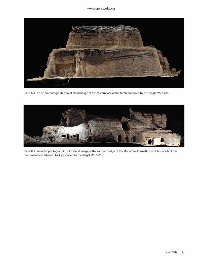
Color Plate 46
www.aeraweb.org
Color Plate 47
www.aeraweb.org
Plate 47.1. An orthophotographic point cloud image of the eastern face of the tomb produced by the Riegl LMS-Z420i.
Plate 47.2. An orthophotographic point cloud image of the southern edge of the Moqattam Formation, which is north of the monument and adjacent to it, produced by the Riegl LMS-Z420i.

www.aeraweb.org