Embed Size (px)
Citation preview
The following information and photographs are what I did to build the kit. Your methods and needs
may differ from this which is fine. There is no right or wrong way if you are used to scratch building. The idea is to make a final model that fits your railroad.
I do recommend having trucks and couplers on hand so they can be used to determine your final
dimensions. Most kits include grab & step irons, truss rod wire & turn buckles and other various items
for each particular car. You can add additional items as you desire. Most detail parts are available from Grandt Line, Tichy and others.
You can also modify the wood parts to get a shorter or narrower car, or you may want to make a full
width bolster or you might want to add a name board or an end beam. The point is, make it your own. Now for my tips.
Gondola Assembly
These photos are from my assembly of the 22' long x 7' wide gondola. This car is based on the Maine prototype Bridgton & Saco River RR low side 10T coal car. You can make different modifications to this car to fit your RR. Photo of the original is below for your reference. Make sure you have all the parts shown in the photo. Any missing parts will be sent free of cost. Also, have your trucks and couplers on hand so you can complete your assembly to work with them. Some of your parts and modifications will depend on these and on you making them match the other cars on your railroad. The procedures given here is how I built the model. You may find better methods and of course are free to use what works for you. Just try not to get ahead of yourself and get blocked into a corner.
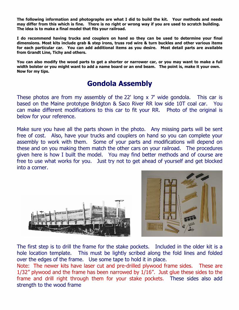
The first step is to drill the frame for the stake pockets. Included in the older kit is a hole location template. This must be lightly scribed along the fold lines and folded over the edges of the frame. Use some tape to hold it in place. Note: The newer kits have laser cut and pre-drilled plywood frame sides. These are 1/32” plywood and the frame has been narrowed by 1/16”. Just glue these sides to the frame and drill right through them for your stake pockets. These sides also add strength to the wood frame
EDGE VIEW Use a #64 (.036) drill for the holes and try to keep them straight across the frame. There is a small amount of play with this size hole to adjust the pockets when you glue them on. Important Note: I have found that some older frames for the kits may have one of the cross members cut in the wrong location. Do NOT use the cross members to locate the Needle Beams in the older kits (before Nov.2014)! The Needle Beams should be 4’6” from each bolster edge. Next is to glue the Needle Beams and Bolsters to the frame. The Needle beams should be located 1/3rd of the way between the bolsters, 4’6” from the edge of the bolsters. Make sure these are glued on square to the frame. The needle beams must be drilled to accept the Queen Posts. A #58 (.042) drill should work OK. The holes should be 1/8" from the outside end of the beam/frame. New kits have the needle beams with laser marked hole locations. And new kits also have 4 truss rods and are designed for the 4 to be used. Next is to cut four shallow grooves into the top of each bolster to line up with the queen posts. This is to accept the truss rods and only need to be .025-.030 deep. The TOP of the frame has laser scribed lines where these shallow cuts should be located. I use my small hand saw or an Xacto #11 saw blade to cut these. Now you can glue the queenposts into the holes with CA (super glue) and make sure they are properly lined up with the end grooves to accept the truss rods.
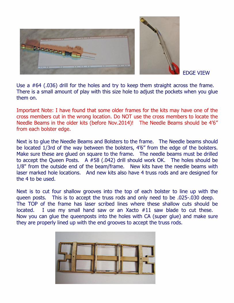
The kit includes flat bolsters that you need to taper the ends as shown. I simply carve them with my knife and sand as needed. I leave a small flat at the outside ends (not a chisel edge). Then, glue the Bolsters in place. Next, drill the bolster for the truck screws using the top side hole of the bolster as a guide. Now, take the truss rods (4" lengths) and lay them over the queen posts with approximately equal distance on either side. Note: New kits have 4 truss rods and appropriate queenposts and turnbuckles. Mark the wire with a marker or sharpie on the outside edge of each queenpost. This is where they will be bent. Now hold the wire in a flat plier and put a slight bend in each side. Do NOT over bend the angle of the wire, less is better. And make sure the bends on each truss wire are in line with the other.
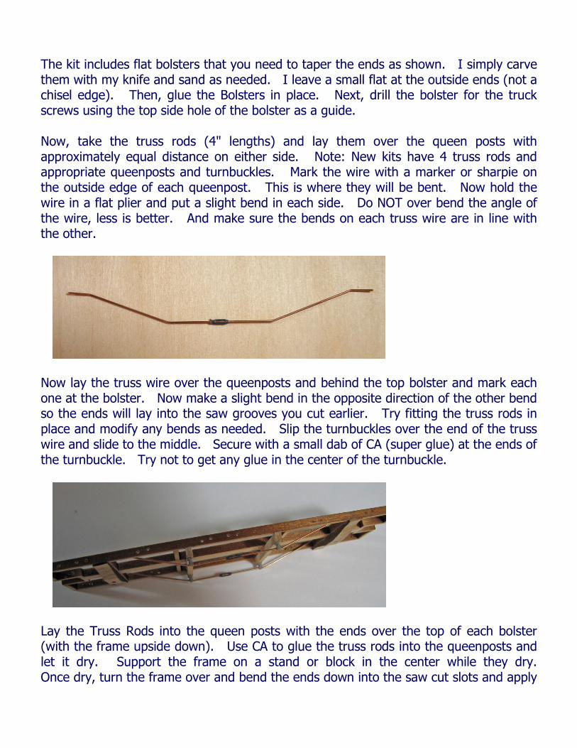
Now lay the truss wire over the queenposts and behind the top bolster and mark each one at the bolster. Now make a slight bend in the opposite direction of the other bend so the ends will lay into the saw grooves you cut earlier. Try fitting the truss rods in place and modify any bends as needed. Slip the turnbuckles over the end of the truss wire and slide to the middle. Secure with a small dab of CA (super glue) at the ends of the turnbuckle. Try not to get any glue in the center of the turnbuckle.
Lay the Truss Rods into the queen posts with the ends over the top of each bolster (with the frame upside down). Use CA to glue the truss rods into the queenposts and let it dry. Support the frame on a stand or block in the center while they dry. Once dry, turn the frame over and bend the ends down into the saw cut slots and apply
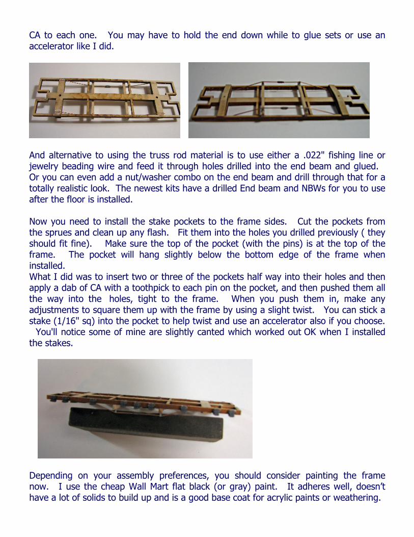
CA to each one. You may have to hold the end down while to glue sets or use an accelerator like I did.
And alternative to using the truss rod material is to use either a .022" fishing line or jewelry beading wire and feed it through holes drilled into the end beam and glued. Or you can even add a nut/washer combo on the end beam and drill through that for a totally realistic look. The newest kits have a drilled End beam and NBWs for you to use after the floor is installed. Now you need to install the stake pockets to the frame sides. Cut the pockets from the sprues and clean up any flash. Fit them into the holes you drilled previously ( they should fit fine). Make sure the top of the pocket (with the pins) is at the top of the frame. The pocket will hang slightly below the bottom edge of the frame when installed. What I did was to insert two or three of the pockets half way into their holes and then apply a dab of CA with a toothpick to each pin on the pocket, and then pushed them all the way into the holes, tight to the frame. When you push them in, make any adjustments to square them up with the frame by using a slight twist. You can stick a stake (1/16" sq) into the pocket to help twist and use an accelerator also if you choose. You'll notice some of mine are slightly canted which worked out OK when I installed the stakes.
Depending on your assembly preferences, you should consider painting the frame now. I use the cheap Wall Mart flat black (or gray) paint. It adheres well, doesn’t have a lot of solids to build up and is a good base coat for acrylic paints or weathering.

I sprayed a coat of Badger Model Flex Light Tuscan Oxide Red over that. I use lead sheet, cut to fit, for weights on the underside of the car. Use the frame as a template and cut pieces to fit in all the panels. ( the picture shown is from the flat car kit) I actually cut the lead sheet after the car was assembled and had to make a couple pieces smaller to get them in. This will work fine too.
Note: Before the next step you need to check your coupler height. Temporarily install your trucks on the car and align it on a piece of track with either another car that has couplers or use your coupler gauge to determine the location of the coupler box on this car. The latest kits come with the block still in the frame coupler location. You can cut this out if you need your coupler to be up high or you can split the block to use as a shim to lower your coupler or leave the block in place if you need to mount your coupler under the frame. After making that decision you can now move on to the next step, gluing the block to the underside of the floor. You can also remove the trucks for now. Now, glue the floor to the frame, making sure the stake cutouts line up. I used the stakes in the pockets to help align and square the floor. Just before putting the floor on, you should slip the center pieces of lead into the cutouts ( they won’t fit in later) and apply some tacky glue to the tops to hold them against the floor. Apply glue to the top of the frame and place the floor on and hold the center weight tight to the underside of the floor. Either now or later, apply glue to each of the end panel areas and put the lead in place. I use Elmer’s Tacky Glue but Aileene’s Tacky Glue is good also.
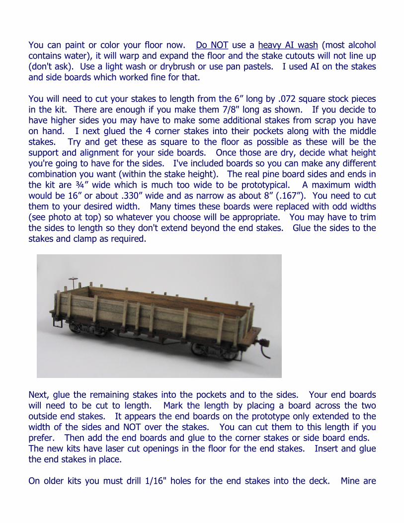
You can paint or color your floor now. Do NOT use a heavy AI wash (most alcohol contains water), it will warp and expand the floor and the stake cutouts will not line up (don't ask). Use a light wash or drybrush or use pan pastels. I used AI on the stakes and side boards which worked fine for that. You will need to cut your stakes to length from the 6” long by .072 square stock pieces in the kit. There are enough if you make them 7/8" long as shown. If you decide to have higher sides you may have to make some additional stakes from scrap you have on hand. I next glued the 4 corner stakes into their pockets along with the middle stakes. Try and get these as square to the floor as possible as these will be the support and alignment for your side boards. Once those are dry, decide what height you're going to have for the sides. I've included boards so you can make any different combination you want (within the stake height). The real pine board sides and ends in the kit are ¾” wide which is much too wide to be prototypical. A maximum width would be 16” or about .330” wide and as narrow as about 8” (.167”). You need to cut them to your desired width. Many times these boards were replaced with odd widths (see photo at top) so whatever you choose will be appropriate. You may have to trim the sides to length so they don't extend beyond the end stakes. Glue the sides to the stakes and clamp as required.
Next, glue the remaining stakes into the pockets and to the sides. Your end boards will need to be cut to length. Mark the length by placing a board across the two outside end stakes. It appears the end boards on the prototype only extended to the width of the sides and NOT over the stakes. You can cut them to this length if you prefer. Then add the end boards and glue to the corner stakes or side board ends. The new kits have laser cut openings in the floor for the end stakes. Insert and glue the end stakes in place. On older kits you must drill 1/16" holes for the end stakes into the deck. Mine are
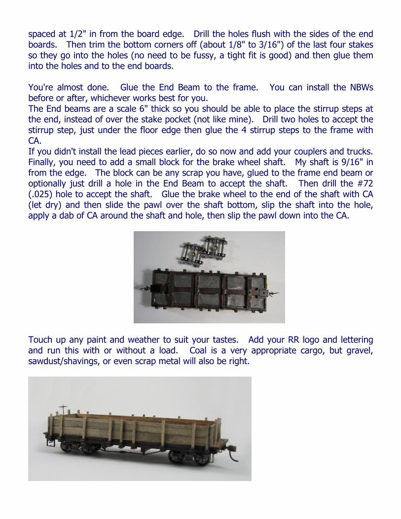
spaced at 1/2" in from the board edge. Drill the holes flush with the sides of the end boards. Then trim the bottom corners off (about 1/8" to 3/16") of the last four stakes so they go into the holes (no need to be fussy, a tight fit is good) and then glue them into the holes and to the end boards. You're almost done. Glue the End Beam to the frame. You can install the NBWs before or after, whichever works best for you. The End beams are a scale 6" thick so you should be able to place the stirrup steps at the end, instead of over the stake pocket (not like mine). Drill two holes to accept the stirrup step, just under the floor edge then glue the 4 stirrup steps to the frame with CA. If you didn't install the lead pieces earlier, do so now and add your couplers and trucks. Finally, you need to add a small block for the brake wheel shaft. My shaft is 9/16" in from the edge. The block can be any scrap you have, glued to the frame end beam or optionally just drill a hole in the End Beam to accept the shaft. Then drill the #72 (.025) hole to accept the shaft. Glue the brake wheel to the end of the shaft with CA (let dry) and then slide the pawl over the shaft bottom, slip the shaft into the hole, apply a dab of CA around the shaft and hole, then slip the pawl down into the CA.
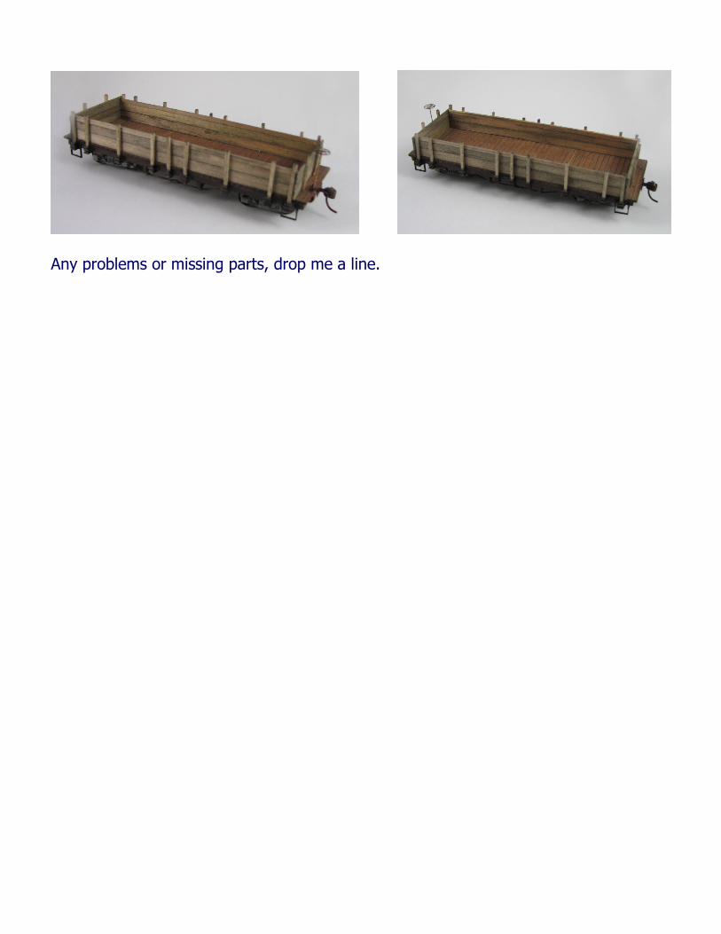
Touch up any paint and weather to suit your tastes. Add your RR logo and lettering and run this with or without a load. Coal is a very appropriate cargo, but gravel, sawdust/shavings, or even scrap metal will also be right.
Any problems or missing parts, drop me a line.