Embed Size (px)
Citation preview

1
Golf Prosthesis Final Design Report
Sponsor: QL+
Team Members:
Joseph Barcus: [email protected]
Lauren Wilson: [email protected]
Ryan Satcher: [email protected]
December 2nd, 2011

2
Confidentiality Agreement This document is to be held confidential under the authority of Quality of Life Plus (QL+). All
information in this document is under legal ownership of QL+ and their associates. For more
information regarding the terms and conditions of this report please contact Tom Mase of the
Mechanical Engineering department at [email protected].

3
Contents
Introduction .................................................................................................................................................. 8
Sponsor Background and Needs ............................................................................................................... 8
Problem Definition .................................................................................................................................... 8
Objectives/Specification Development .................................................................................................... 9
Project Management Plan ...................................................................................................................... 12
Outstanding Tasks ............................................................................................................................... 12
Background ................................................................................................................................................. 14
Existing Products ..................................................................................................................................... 14
Personal Contacts ................................................................................................................................... 17
Jim Taylor ............................................................................................................................................ 17
John Lawson ........................................................................................................................................ 18
List of Applicable Standards .................................................................................................................... 20
USGA Limitations for Modified Equipment......................................................................................... 20
Design Development ................................................................................................................................... 21
Initial Concept Overview ..................................................................................................................... 21
Conceptual Designs ................................................................................................................................. 21
Adaptive Golf Sleeve ........................................................................................................................... 21
Single Arm Design ............................................................................................................................... 22
Adaptive Golf Glove ............................................................................................................................ 23
Slotted Wrist ....................................................................................................................................... 25
Concept Selection ................................................................................................................................... 27
Supporting Preliminary Analysis ............................................................................................................. 28
Description of Final Designs ........................................................................................................................ 30
Adaptive Golf Sleeve ............................................................................................................................... 30

4
Golf Cuff .................................................................................................................................................. 32
Cost Analysis ........................................................................................................................................... 34
Bill of Materials ................................................................................................................................... 34
Travel Accommodations ..................................................................................................................... 34
Product Realization ..................................................................................................................................... 35
Manufacturing Process ........................................................................................................................... 35
Design Verification Plan .............................................................................................................................. 37
Testing ..................................................................................................................................................... 37
Specification Verification ........................................................................................................................ 40
Conclusion ................................................................................................................................................... 41
What we learned ..................................................................................................................................... 41
Successes ................................................................................................................................................ 41
Final Recommendations ............................................................................................................................. 43
Appendix ..................................................................................................................................................... 38
A. Initial Concept Development .......................................................................................................... 38
Design Selection Process ..................................................................................................................... 38
Top Concepts ...................................................................................................................................... 40
Slotted Wrist ........................................................................................................................................... 40
Specification Satisfaction for Top Concepts ........................................................................................ 44
B.1: Initial Slotted Wrist Solidworks Model ............................................................................................ 44
B.2: Golf sleeve drawings ........................................................................................................................ 45
B3: Golf Cuff Drawing .............................................................................................................................. 46
B.4: Hook drawings ................................................................................................................................. 47
B.5: Final Slotted Wrist Drawings............................................................................................................ 51
B.6 Forearm Attachment Solid works ModelB.7 Preset Wrist Solid works Design ................................ 51

5
C.Gantt Chart .......................................................................................................................................... 60

6
List of Figures Figure 1: United States double golf amputee patent………………………..……………………………… pg.13 Figure 2: Ping quadruple amputee…………………………………………………………………………………… pg.14 Figure 3: TRS grip………………………………………………………………………………………………………….... pg.14 Figure 4: Existing products, right hook golf adaptation…………………………….……………………… pg.15 Figure 5: Existing products, Right hook and clamp support golf adaptation…….………….…… pg.15 Figure 6: Jim Taylor’s follow through……………………………………………………………………………….. pg.15 Figure 7: Jim Taylor’s address at the ball………………………………………………………………………….. pg.15 Figure 8: Drawing of the design John Lawson uses…………………………………………………………… pg.18 Figure 9: Sketch of golf sleeve…………………………………………………………………………………………. pg.20 Figure 10: Sketch of the single arm design………………………………………………………………………… pg.21 Figure 11: Sketch of golf glove…………………………………………………………………………………………… pg.22 Figure 12: Sketch of a typical hook…………………………………………………………………………………….. pg.22 Figure 13: Sketch of the top view of the golf glove design…………………………………………………. pg.23 Figure 14: Sketch of the amputee at address…………………………………………………………………….. pg.23 Figure 15: Sketch of right view of the slotted wrist……………………………………………………………. pg.25 Figure 16: Sketch of front view of the slotted wrist……………………………………………………………. pg.25 Figure 17: Sketch of cross-sectional view of the slotted wrist……………………………………………. pg.25 Figure 18: Sketch of slotted wrist and arm bar………………………………………………………………….. pg.25 Figure 19: Sketch of slotted wrist and quick release………………………………………………………….. pg.25 Figure 20: Model and analysis of the force at impact………………………………………………………… pg.27 Figure 21: Model and analysis for the threaded fastener………………………………………………….. pg.28 Figure 22: Labeled model of the golf sleeve design……………………………………………………………. pg.29 Figure 23: Labeled model of the bottom of the golf sleeve design………………………………..….. pg.30 Figure 24: Labeled model of golf cuff design……………………………………………………………………… pg.31 Figure 25: Model of prosthetic arms attached to golf cuff…………………………………………………. pg.32 Figure 26: Overhead view of two part mold…….…………………………………………………………….….. pg.34 Figure 27: Final golf cuff design…………………………………………………………………………………………. pg.35 Figure 28: Final golf sleeve design…………..…………………………………………………………………………. pg.35 Figure 29: Photos of Jim Taylor testing final designs………………………………………………………….. pg.36 Figure 30: Testing designs with forearm replacements………………………………………………………. pg.37 Figure 31: Jim Taylor’s attempt to use the golf cuff……………………………………………………………. pg.39 Figure 32: Jim Taylor using his current device……………………………………………………………………. pg.42 Figure 33: Example of standard angle at address………………………………………………………………. pg.43 Figure 34: View of Jim’s interlocking grip…………………………………………………………………………… pg. 44

7
List of Tables Table 1: Design Specifications……………………………………………………………………………………………….. pg.9 Table 2: Bill of materials……………………………………………………………………………………………………….. pg.33 Table 3: Travel Accommodations………………………………………………………………………………………….. pg.33 Table 4: Jim Taylor test results…………………………………………………..………………………………………….. pg.37 Table 5: Comparison of current product to our final designs…………………………………………………. pg.41

8
Introduction
Sponsor Background and Needs
Missing Links consists of fourth and fifth year Cal Poly students working on a senior project with QL+ (Quality of Life Plus), an organization dedicated to improving the lives of wounded veterans injured while serving our country in Iraq and Afghanistan. These individuals are also known as wounded warriors. The project is specifically dedicated to help bilateral amputees swing a golf club and make consistent contact with a golf ball. The goal of this project is to design a golf prosthesis to help these individuals experience the game of golf they enjoyed before they were injured. The stakeholders for this project include the sponsor QL+, wounded warriors (specifically bilateral amputees, as the primary customers for our product), prosthetists who can implement our attachment for further applications, and the team of engineers developing a solution.
Problem Definition
To construct a device allowing a bilateral amputee to swing a golf club consistently and effectively. Our primary goal is to create a device that allows a bilateral amputee to use their everyday prosthetic arms to swing a golf club. Our secondary goal is creating a device that also functions in a way so that anyone can test it, including people who have full use of both arms. This secondary goal is necessary because upper extremity bilateral amputees are extremely rare. By designing a device that anyone can test, we can allot ourselves more time to make proper adjustments to our device in the future. Our final goal is to design a device that the amputee can independently attach and detach from the golf club, allowing them to play golf independently without the assistance of others.

9
Objectives/Specification Development
The primary objective of this golf prosthesis project is to construct a device that allows bilateral
amputees to swing a golf club consistently and effectively. In order to achieve this objective we
developed secondary objectives for our solution process in order to satisfy the customer as best as
possible. One secondary objective includes developing a device that bilateral amputees can use
independently. Currently, there are no existing products that allow the user to play golf without
personal assistance. This secondary objective will separate our device from any existing products. Our
final objective is to develop a system that allows anyone to test the device, whether they are an
amputee or have complete use of their arms. This simplifies the testing stage of our design, allowing us
to make proper adjustments in less time.
After meeting with John Lawson and talking with Jim Taylor over the phone we realized how important
their hooks are. Hooks, also known as terminal devices, screw into the end of prosthetic arms. Both
John and Jim refer to their prosthetic hooks as their hands. Their hooks make their lives much easier.
After taking this into consideration, another secondary objective was created which establishes that the
user to must have full ability to use of one of their arms while using our device. By pursuing this goal we
are attempting to insure that the user will be able to participate in other activities while golfing, such as
drinking a beer or driving a golf cart.
We developed the customer requirements based on what the customer wants. Our customer
requirements are listed in the Appendix in the QFD. The QFD, or house of quality, is a template used to
develop the customer’s wants, how their wants will be met, competitive analysis based on their needs,
and quantify how the needs will be met.
In order to establish our customer requirements we asked John Lawson and Jim Taylor what they would
want out of a prosthetic golf attachment. As a result, a list of the top five customer wants were created
including playing 18 holes of golf, participating in all aspects of the game, playing golf independently of
others, and creating a device that was inexpensive and light weight. We developed nine customer
specifications that encompass all of the customer wants. This list includes price, weight, ease of use,
comfort, interchangeability, durability, reliability, aesthetics, and independent use.
After establishing the customer specifications in the QFD we developed a decision matrix to establish
the targets of each specification as well as the risk and compliance. The list of all the design
specifications, their targets, risks and compliances can be seen below in Table 1.

10
Table 1: Design specifications table including requirements, tolerance, risk, and compliance
To determine the targets for each requirement we researched existing products. After researching we
quantified each specification with units and tolerances such as two pounds for the weight and $200 for
the price.
The risk assessment details how difficult it will be to meet each specification. The two high risk
specifications include interchangeability and independent use. Interchangeability and independent use
will be difficult to meet because they both rely completely on the user’s available motor skills and
patience. We also want the user to be able to put on and take off the golf prosthesis independently and
in fewer than 30 seconds in order for them to focus more on playing golf instead of spending time
manipulating the attachment.
After reviewing our design specifications we narrowed the definition of our objectives by setting targets.
The main objective focuses on the consistency and effectiveness of the golf swing. The specifications
that define this objective are ease of use, interchangeability, and comfort. We defined ease of use as
the user can make contact with a golf ball 9 out of 10 times. By achieving this goal we’ve established a
foundation for the user to develop their own golf skills using the golf prosthesis. The target for
Spec. # Parameter Description
Requirement or Target (units)
Tolerance Risk Compliance
1 Price < $200 Max L A
2 Weight < 2 lbs. ± 0.5 L A,T,S
3
Ease of Use
User can make contact with golf
ball 9/10 times with their given skill set
Min M T,S
4
Comfort
User should swing a golf club with no
abnormal positioning of their
body
Min L T
5
Interchangeability Change between
devices in under 30 seconds
Max H T,S
6
Durability 10 million swings
before failure (infinite use)
Max M A,I
7 Reliability 99% Min M A,I
8
Aesthetics Device is appealing
to the eye to at least 80% of users
Min L S
9 Independent Use 100% Max H T,S

11
interchangeability is to allow the user to take off and put on the prosthetic device in 30 seconds or less.
This target gives the user freedom to use other prosthetic devices on the golf course to help them drive
a golf cart or eat food. The last target that will help the user make a consistent and effective golf swing
is to make sure they don’t need to contort their bodies into abnormal positions. If the user forces their
bodies into awkward positions it will affect how well they’ll be able to swing a golf club. The device
needs to be comfortable so they can play golf to their maximum skill level.

12
Project Management Plan
All group members are responsible for research, attending meetings, and idea generation. The specific responsibilities of each individual are listed below. These responsibilities are subjected to change as the project develops. Deadlines and tasks for the remainder of this project are laid out in the Gantt Chart located in Appendix F. Lauren Wilson:
Record and keep track of contact’s information
Manage team’s schedule
Establish weekly duties for each team member
Establish short term and long term goals for the project
Manage project’s budget
Set up meetings with outside parties
Golf cuff design
Ryan Satcher:
Manufacturing
Prototype fabrication
Material selection and properties
Purchasing materials
Forearm attachment
Joseph Barcus:
Testing plans and procedures
Product safety and warnings
Analyze stresses and fatigue loading at impact
Calculations and statistical analysis of testing data
Develop a user’s manual
Golf sleeve design
Outstanding Tasks
Create a simulation for a worst case scenario and analyze the forces generated at impact. For example, the forces generated against the club face when taking a large divot. Use that force to perform finite element analysis and find the largest stress concentrations.
Establish contact with a double arm amputee wounded warrior: Contact has been established with two double amputee golfers, John Lawson and Jim Taylor, however neither are wounded warriors. There is a wounded warrior golf course in Washington, but thus far we have had no luck finding a bilateral amputee
Testing: testing of our prototypes will be accomplished during fall quarter and possibly spring quarter. For the purposes of testing, we would like to fly Jim Taylor out to San Luis Obispo to test all three of our devices. If we don’t get enough feedback on our designs, we will use the

13
forearm attachment, shown previously in the final design section, to finish up testing. With this device, we plan on hitting many balls on the range to see how well the device works and how we can make it better. More information about testing is located in the testing and construction section above.
Iterating the design: The design will need to be iterated many times to create the best solution. This will be done all throughout fall quarter.

14
Background
Existing Products
Although current information regarding bilateral amputee golf prosthetics is limited, the need is still very apparent. Wounded veterans often suffer from anger, depression, and post-traumatic stress disorder after returning home from combat; especially soldiers who suffer a life changing injury such as the amputation of both arms. Initially, an amputation sounds incredibly debilitating, but the strong will and determination of bilateral amputees goes above and beyond the general public’s expectations. In addition, golf has been shown to be an important part of the rehabilitation process for some amputees as mentioned in the Enterprise-Examiner, “(golf helps patients with) working on their balance and strength and their mental fitness”. Because of the physical and mental rehabilitation benefits of playing golf, it is imperative that a prosthetic device be engineered in a way that makes it easier for wounded warriors to start playing golf again. Currently there are only a handful of designs for golf prosthetics that address the need of bilateral amputees. One design was found through a US patent search and is shown in Figure 1 below. This system is unique because it locks both prosthetic arms to each other so they remain in the same plane during a golf swing. The system provides radial and linear rotation during the backswing for a full range of motion. Two other designs that incorporate standard body powered prosthetic hooks are also shown on the following page.
Figure 1: United States Patent 6582473 for swing regulating mechanism and wrist emulator for assisting an
amputee in swinging a golf club.

15
Another design, created by Ping for a quadruple amputee, involves a golf adaptation where the shaft of the club screws directly into the prosthetic of the amputee’s right arm, seen in Figure 2. This design was then used to create a single unilateral swing motion.
Figure 2: Ping’s golf prosthetic for a quadruple amputee TRS currently makes a golfing attachment for single arm amputees called the Eagle Golf TD, designed by Bob Radocy of TRS, that can create either a uni-lateral or bi-lateral (incorporating a wrist hinge) swing (Figure 3). A TRS grip has been donated by Bob Radocy to see if it could be incorporated into our design.
Figure 3: This prosthetic was developed by TRS and allows for use of unmodified clubs.

16
Other golfing adaptations have been created to assist double arm amputees by incorporating their hooks into the golf swing. Figure 4 is a device where the end of the golf club is inserted directly into the left prosthetic arm. Figure 5 is a device that clamps on the shaft of the golf club and attaches to the wrist of the left prosthetic arm.
Figure 4: Right hook golf adaptation Figure 5: Right hook and clamp support golf adaptation Jim Taylor, a double arm amputee, uses state of the art golf prosthetic equipment. He has special golf prosthetic arms that cost $10,000 and give him a unique advantage over other double arm amputee golfers. Figures 6 and 7 show the current prosthetics Jim Taylor uses.
Figure 6: Jim Taylor’s follow through Figure 7: Jim Taylor’s address at the ball

17
After talking with Cal Poly Kinesiology Professor Kevin Taylor, it became apparent that the prosthetic design must not give the user a distinct advantage over a fully capable golfer. If an autonomous device is developed that swings the golf club for the amputee, then that device is taking away the skill level required for golf. This is also in accordance with the USGA regulation 14-3 which is located in the list of applicable standards section. Finally, regardless of what we design, we are aware that current hook or claw prosthetics can also be used to actively and independently play golf with no modifications as proven by disabled Golfer Dan Balsiger. Dan plays golf with his standard prosthetic hooks using a unilateral swing motion. In addition, other double arm amputees have also made their mark in golf using other golf adapted prosthetics such as Jim Taylor. Jim is a disabled golfer from Longview, WA who actively competes in tournaments sponsored by the National Amputee Golf Association (NAGA), and who has already recorded 17 hole-in-ones.
Personal Contacts
Jim Taylor
On April 10, 2011, our senior project team came in contact with Jim Taylor. He is a double arm amputee who was injured in a severe electrical accident on May 5, 1965, where he was shocked with 7,300 volts of electricity from a nearby power line, at the age of 10. In the accident Jim broke his back and suffered severe tissue damage causing his arms to be amputated. His left arm was amputated just below the elbow while his right arm was amputated just above the elbow. Shortly after his accident Jim Taylor picked up the game of golf, and has been playing now for the past 40+ years. “‘The game is my therapy. It’s physical therapy and it’s good for me inside, too. It gives me a sense of accomplishment,’ said Taylor, who has undergone 20 surgeries in his lifetime, including four on his back” (The Daily News Online).
Jim is not your average golfer. Although a double arm amputee, he is amazingly talented and has 17 hole-in-ones, a 12 handicap, and an assortment of amputee golf titles to show for it. “In so many mysterious ways, golf has helped Taylor. . . level the playing field. . . ‘If you can golf, you can just be a golfer. All handicaps are out the door,’ said Taylor” (The Daily News Online). Jim currently lives in Washington State where his current golf set up is based around a set of custom built golf arms, which retail for about $10,000. Using his golf arms, he secures the golf club between his hooks with an interlocking grip; in the same fashion an able bodied golfer might grip a golf club, except imagine doing so using only two fingers on each hand. To achieve better control, Jim uses athletic tape, which he wraps around his hooks to increase their size, which increases the surface area contact with the golf club. This can be seen in figures 6 and 7 in the Existing Products Section of this report. He then takes further measures to ensure that the club is not lost during the golf swing by securing the butt end of the club into a C-shaped groove that is attached to his left forearm. Recently, Jim has added to his design by incorporating bungee cords, which he wraps over his hooks to increase their grip strength. Today, the golf prosthetic Jim uses is the result of 15 years of engineering, adjustments, and many iterations.
18
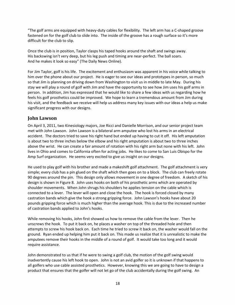
“The golf arms are equipped with heavy-duty cables for flexibility. The left arm has a C-shaped groove fastened on for the golf club to slide into. The inside of the groove has a rough surface so it’s more difficult for the club to slip. Once the club is in position, Taylor clasps his taped hooks around the shaft and swings away. His backswing isn’t very deep, but his leg push and timing are near-perfect. The ball soars. And he makes it look so easy” (The Daily News Online). For Jim Taylor, golf is his life. The excitement and enthusiasm was apparent in his voice while talking to him over the phone about our project. He is eager to see our ideas and prototypes in person, so much so that Jim is planning on driving down from Washington to visit us in middle to late May. During his stay we will play a round of golf with Jim and have the opportunity to see how Jim uses his golf arms in person. In addition, Jim has expressed that he would like to share a few ideas with us regarding how he feels his golf prosthetics could be improved. We hope to learn a tremendous amount from Jim during his visit, and the feedback we receive will help us address many key issues with our ideas a help us make significant progress with our designs.
John Lawson
On April 3, 2011, two Kinesiology majors, Joe Ricci and Danielle Morrison, and our senior project team met with John Lawson. John Lawson is a bilateral arm amputee who lost his arms in an electrical accident. The doctors tried to save his right hand but ended up having to cut it off. His left amputation is about two to three inches below the elbow and his right amputation is about two to three inches above the wrist. He can create a fair amount of rotation with his right arm but none with his left. John lives in Ohio and comes to California often for acting jobs. He likes to come to San Luis Obispo for the Amp Surf organization. He seems very excited to give us insight on our designs. He used to play golf with his brother and made a makeshift golf attachment. The golf attachment is very simple; every club has a pin glued on the shaft which then goes on to a block. The club can freely rotate 90 degrees around the pin. This design only allows movement in one degree of freedom. A sketch of his design is shown in Figure 8. John uses hooks on both of his prosthetic arms which are operated by shoulder movements. When John shrugs his shoulders he applies tension on the cable which is connected to a lever. The lever will open and close the hook. The hook is forced closed by many castration bands which give the hook a strong gripping force. John Lawson’s hooks have about 20 pounds gripping force which is much higher than the average hook. This is due to the increased number of castration bands applied to John’s hooks. While removing his hooks, John first showed us how to remove the cable from the lever. Then he unscrews the hook. To put it back on, he places a washer on top of the threaded hole and then attempts to screw his hook back on. Each time he tried to screw it back on, the washer would fall on the ground. Ryan ended up helping him put it back on. This made us realize that it is unrealistic to make the amputees remove their hooks in the middle of a round of golf. It would take too long and it would require assistance. John demonstrated to us that if he were to swing a golf club, the motion of the golf swing would inadvertently cause his left hook to open. John is not an avid golfer so it is unknown if that happens to all golfers who use cable assisted prosthetics. However, knowing this we are going to have to design a product that ensures that the golfer will not let go of the club accidentally during the golf swing. An

19
interesting point to note is that John can easily detach the cable from the lever of his left prosthetic arm, which then permanently prevents his left hook from opening until the cable is reattached. When asked if he would rather have a product that allows complete independent use or a product that looks like a natural golf swing, he said without hesitation that he would rather have a product that allows complete independence of use. John said the hardest part of golf is teeing up the golf ball. He has to pick up both tee and ball at the same time and delicately place it in the ground. John said that the easiest part of golf is the short game and putting. John is planning on coming back to California in May to help us further develop our prototypes.
Figure 8: Drawing of the design John Lawson (double arm amputee) uses

20
List of Applicable Standards
USGA Limitations for Modified Equipment
14-3. Artificial Devices, Unusual Equipment and Unusual Use of Equipment
The United States Golf Association (USGA) reserves the right, at any time, to change the Rules relating to artificial devices, unusual equipment and the unusual use of equipment, and make or change the interpretations relating to these Rules.
A player in doubt as to whether use of an item would constitute a breach of Rule 14-3 should consult the USGA.
A manufacturer should submit to the USGA a sample of an item to be manufactured for a ruling as to whether its use during a round would cause a player to be in breach of Rule 14-3. The sample becomes the property of the USGA for reference purposes. If a manufacturer fails to submit a sample or, having submitted a sample, fails to await a ruling before manufacturing and/or marketing the item, the manufacturer assumes the risk of a ruling that use of the item would be contrary to the Rules.
Except as provided in the Rules, during a stipulated round the player must not use any artificial device or unusual equipment, or use any equipment in an unusual manner:
a. That might assist him in making a stroke or in his play; or b. For the purpose of gauging or measuring distance or conditions that might affect his play; or c. That might assist him in gripping the club, except that:
(i) plain gloves may be worn; (ii) resin, powder and drying or moisturizing agents may be used; and (iii) a towel or handkerchief may be wrapped around the grip.
Exceptions:
1. A player is not in breach of this Rule if (a) the equipment or device is designed for or has the effect of alleviating a medical condition, (b) the player has a legitimate medical reason to use the equipment or device, and (c) the Committee is satisfied that its use does not give the player any undue advantage over other players.
2. A player is not in breach of this Rule if he uses equipment in a traditionally accepted manner.
Penalty for Breach of Rule 14-3: Disqualification.
Note: The Committee may make a Local Rule allowing players to use devices that measure or gauge distance only.

21
Design Development
Initial Concept Overview
After contacting both John Lawson and Jim Taylor we realized how much they rely on the use of their
prosthetic hook attachments. In the initial emails we had with John he stressed how important his hooks
are to him, that his hooks are essentially his “hands.” Jim Taylor confirmed this statement. As a result,
we knew we now had to design our solution to incorporate the capability of their prosthetic hooks.
With this in mind, we decided to head in a new direction, removing our initial concepts of the pre-set
wrist, the magnetic wrist, and bevel gear designs. The initial concept development, selection, and
specification satisfaction can be viewed in Appendix A.
Conceptual Designs
Adaptive Golf Sleeve
The adaptive golf sleeve is a concept derived from the TRS Grip, a terminal device used for single arm
amputee golfers. The concepts we developed before meeting John Lawson and Jim Taylor incorporated
the TRS grip, and as a result we were familiar with its functionality and application. After our interview
with John he stressed that using a device independently is more important than how easy it is to use.
With these new design targets in mind we wanted to develop a device allowing the bilateral amputee to
keep their hook attachments on the entire time.
A hand drawing of our initial golf sleeve concept is shown below in Figure 9. The shape of the sleeve is
similar to that of the TRS Grip. But unlike the TRS Grip we don’t want the sleeve to directly attach onto a
prosthetic arm. We want the user to be able to apply the sleeve on to a golf club shaft and use their
hooks to hold on to the club as if they were gripping the club with their hands. The sleeve is
approximately twice the length of the TRS Grip providing more stability during the golf swing.
Figure 9: Sketch of golf sleeve

22
In order to make the sleeve entirely independent, a ring extends from the front of the sleeve so the user
can use their hook to slide and pull the sleeve up the shaft of the club. The sleeve also has inlets on each
side where the users hooks are inserted, simulating a golf grip. The sleeve would be made from
polyurethane, similar to the TRS Grip, allowing some flexion when a bending moment is applied.
One design consideration for the golf sleeve is how the user will be able to keep the club in a single
plane during the swing. The hook inlets will need to be adjusted so the user has more control of the
club. Another consideration for the golf sleeve is how well the sleeve will be able to slide up the shaft of
the club and the grip without encountering large amounts of friction. This was a concern for us when
testing the capabilities of the TRS Grip. Applying the TRS Grip onto the shaft is simple but sliding it high
enough onto the grip proved extremely difficult. In order to avoid this complication we will need to
design the sleeve with a larger inner diameter, making it easier to apply onto a golf club.
Single Arm Design
As stated before with the adaptive golf sleeve, our concepts have now shifted so that the user still has
the ability to use their prosthetic hook attachments and they can use the device independently. The
single arm design is an effective and simple solution for double arm amputees that allow them to have
complete use of one of their arms at all times. A sketch of the single arm design can be seen below in
Figure(10).
Figure 10: Sketch of the single arm design
The sketch depicts a collar that would be attached onto the prosthetic arm, preferably the right arm.
The collar would need to be attached to the arm of the user before playing golf and it would stay there
throughout the round. Attached to the collar is a c-clamp that is attached to the collar via a bungee

23
cord. The c-clamp is put in place in order to clamp onto the grip of the club. The user would then grip
the shaft with their prosthetic hook. The bungee cord is applied between the collar and clamp to
simulate the rotation of the wrist during the backswing. So when the user pulls the club back, the
bungee cord extends at the top of the backswing creating lag in the downswing. This lag would then
release at impact, the same way a traditional golf swing releases the club at impact.
One consideration for the single arm design is its safety. The c-clamp needs to be secured to the grip of
the club extremely tight so that the momentum of the swing doesn’t force the club to fly out and
potentially hit someone or injure the user. Besides this consideration, the single arm design always
leaves the user with one prosthetic arm free to do whatever they want. It isn’t entirely independent
since an outside party would need to attach the collar onto their prosthetic arm. But once the collar is
attached it won’t need to be modified, and it becomes independent after that.
Adaptive Golf Glove
After finding out that independent use was more important to a bilateral amputee than a device that
allowed for a typical golf swing, we had to brainstorm some new ideas. We wanted something that the
user could easily put on and take off during a round of golf. The idea of a golf glove developed from
learning about Jim Taylor’s secret to increase the surface area of the gripping point. The hooks normally
have a gripping surface area of two or three square centimeters. A golf glove would simply slide on the
hook just like a normal golf glove. At the end of the hooks, there will be a curved slot that the grip can
fit into. The glove will not cover up the lever completely to allow for them to attach/detach their cables.
Figure 12: Sketch of a typical hook
Figure 11: Sketch of the golf glove
24
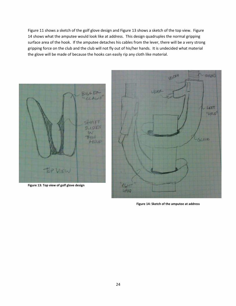
Figure 11 shows a sketch of the golf glove design and Figure 13 shows a sketch of the top view. Figure
14 shows what the amputee would look like at address. This design quadruples the normal gripping
surface area of the hook. If the amputee detaches his cables from the lever, there will be a very strong
gripping force on the club and the club will not fly out of his/her hands. It is undecided what material
the glove will be made of because the hooks can easily rip any cloth like material.
Figure 13: Top view of golf glove design
Figure 14: Sketch of the amputee at address

25
Slotted Wrist
The wrist hinge in a golf swing is a crucial element that adds club head speed as well as the necessary
downward striking force needed to create optimal contact with the golf ball. The slotted wrist idea
originated from this very need, which is apparent for double arm amputee golfers who lack rotation and
the ability to flex their wrists. Our first attempt at this design is show in Figures 15, 16, and 17.
The design attaches to a golf club by attaching the terminal devices on at the head of the golf shaft,
towards the head of the club, and then sliding the slotted wrist and TRS terminal device up the golf shaft
towards the grip. The slotted wrist is then secured in place by friction.
The design in its entirety is composed of two key components. The left arm utilizes the TRS grip
(background fig. 17), and is made from a polyurethane material. The right arm will utilize the Slotted
Wrist design, and will apply a hinging force to the left terminal device during the golf swing as the user
contracts their right bicep. The Slotted Wrist will be made from an aluminum alloy or composite
material for high strength and light weight.
The slotted wrist uses a unique angled slot design, where the golf shaft is allowed to pivot within the
cavity of the slot (Fig. 17). This design allows the user to apply a vertical force to their left wrist, storing
energy in the Eagle TRS terminal device, simply by contracting their right bicep. This allows the user to
hinge the golf club into the proper position on the backswing. During the down swing, the energy
stored in the elastic material of the Eagle TRS grip will be released as the right bicep extends, unhinging
the left wrist and returning some of the stored energy back into the ball at impact. A 3-D model of this
design is located in Appendix D.
After meeting with John Lawson and speaking with Jim Taylor over the phone, we realized that our
initial idea was unacceptable. Our initial idea for the Slotted Wrist would force the user to remove both
hooks from their prosthetic arms, rendering them almost completely helpless to perform other
necessary tasks outside of swinging a golf club. We needed to find a way to incorporate at least one
hook, preferably their dominate hook, into our design. To overcome this challenge we added a wrist
attachment and a quick release lever to our Slotted Wrist design. Now the golf prosthetic could be
secured to their prosthetic arm without the need to remove their dominate hook. The addition of the
quick release allows the Slotted Wrist to be pivoted into and out of position. In this way, the Slotted
Wrist can be used during the golf swing and then repositioned afterwards so that the prosthetic device
is no longer in the way, allowing the user to freely use their hook. Initial sketches of their design
improvements are show below in figures 18 and 19.

26
Forearm
Plates with
Velcro Straps
Golf
Shaft
and Grip
Threaded
Attachment
Figure 15: Right view of slotted wrist
design. As the right bicep contacts the
club is hinged upwards indicated by
the red arrows
Figure 16: Front view of slotted wrist
design.
Figure 17. Cross section of slotted wrist
design showing rotational freedom of the
golf shaft.
Eagle TRS
Grip
Threaded
Attachment
Slotted Wrist
Design
Slotted
Wrist
Figure 18. Wrist attachment and arm bar of the Slotted Wrist
assembly are shown, as the device is pivoted into and out of
position.
Figure 19. Wrist attachment and quick release of Slotted
Wrist assembly.

27
Concept Selection
After reviewing all four conceptual designs we narrowed down our choices in order to develop final
designs. Both designs address the problem definition and meet the objectives we set out to accomplish.
The adaptive golf sleeve is a completely independent device where bilateral amputees will have full use
of their prosthetic hooks while playing golf. The adaptive golf cuff is also a simple design that assists
bilateral amputees with gripping the club as if their hooks were their hands. The cuff will give them the
most realistic golf experience due to its similarity to an actual golf swing. Finally, the slotted wrist
design is a concept we initially developed before we understood the importance of hooks for bilateral
amputees. After understanding the importance of the hooks we adapted the slotted wrist to
incorporate the gripping force of the hooks to assist in swinging a golf club.
One important consideration for our final design is that we only have a general idea for how well a
specific design will be effective. We won’t know the effectiveness of a design until we’ve developed a
prototype and tested it. Also, every one of our concepts will be relatively cheap to manufacture. With
this in mind we decided to proceed with three final designs including the adaptive golf sleeve, adaptive
golf glove, and slotted wrist. We decided to leave out the single arm design due to its lack of feasibility.
It is more effective to have a golf swing that incorporates the use of both arms. Swinging with both
arms will render better results while golfing.

28
Supporting Preliminary Analysis
The primary analysis for our golf prosthetic is focused on a worst case scenario where the user swings a
golf club, using the slotted wrist design, and hits the ground at impact, transferring nearly all
momentum of the club into the ground. By recognizing this problem we can develop a model for how
much force is exerted from the ground onto the club and analyze the threaded fastener that connects
the slotted wrist design onto a prosthetic arm.
Figure 20 below provides a brief sketch, list of assumptions, and governing equation for the problem.
The assumptions are important because they allow us to simplify the problem, making the analysis
feasible. After using the equation for impulse/conservation of momentum, an impact force of 3350N
was calculated.
Figure 20: Model and analysis of the force at impact

29
Once the impact force was calculated we could analyze the force on the threaded fastener to determine
the stiffness. Figure 21 depicts a sketch and list of equations used in order to determine the stiffness of
the threaded fastener. We want to use a light weight metal such as aluminum for the slotted wrist
design so the user has an easier time swinging a golf club. After analyzing an aluminum threaded
fastener, a stiffness of 563304 in-lb. was calculated.
Figure 21: Model and analysis for determining the stiffness of the threaded fastener

30
Description of Final Designs There are two final designs, the golf sleeve and the golf cuff sleeve. Both of which make it easier for a
double arm amputee to securely grip the club while using their everyday prosthetic hooks. The designs
have different ways to grip the club which will accommodate any preference the user has.
Adaptive Golf Sleeve
The adaptive golf sleeve is a modified design based on the TRS Grip. The TRS Grip is a terminal device for
single arm amputees who want to play golf. The general concept of the golf sleeve is similar to the TRS
Grip. Unlike the TRS Grip the Golf Sleeve will be made via the UV Resin rapid prototype machine.
Originally we wanted to manufacture our device using an injection mold. This would allow us to test
different materials from a single mold. After several failed attempts we decided to pursue using the UV
resin rapid prototype machine. The UV Resin isn’t as flexible as polyurethane, but the availability of its
use allows us to make numerous iterations.
The golf sleeve is applied to a golf shaft just like the TRS Grip. The user will slide the grip up the shaft
starting from the lower end where the shaft diameter is smaller. A ring has been added to the top of the
golf sleeve allowing the user to pull the sleeve up the shaft of the club to the desired position.
The main focus of the golf sleeve is to incorporate the use of hooks that bilateral amputee’s use, located
at the ends of their prosthetic arms. In Figure 22 you can see exactly where each hook is applied onto
the sleeve once it has been secured to the shaft of a club.
Figure 22: Labeled model of golf sleeve
Hook insert for right arm
Hook insert for left arm
Assisting ring allows user to pull golf
sleeve up to desired position Upper diameter of sleeve where end
of club would be located

31
In order to simulate an actual golf grip the hook inserts were designed so that the user has to place their
left arm above their right arm just like an actual right handed golf grip. If the bilateral amputee is left
handed then an alternate device can be made to suit their preference. In order to give the user more
security while gripping the club, slots were cut from underneath the sleeve where the bottom of the
hooks can be placed. The slots can be seen in Figure 23.
Figure 23: Labeled model of the bottom of the golf sleeve
Slots designed for the
bottom of the hooks
to be placed into
while gripping the
club

32
Golf Cuff
The golf cuff was designed to provide a stronger and more secure grip on the club. This originated from
Jim Taylor’s golf prosthetic arms. He wraps one of his hooks in several layers of tape which increases
the area of the contact point. If a bilateral amputee just used their hooks to grip the golf club, there
would be a small contact point between the hooks and the grip creating a large concentrated force on
the shaft. John Lawson, an upper extremity bilateral amputee, plays golf with special shafts that were
double wrapped so that the shaft does not snap in half during the golf swing.
The golf cuff increases the area of that contact point so that the user can have more control over the
golf club. The force from the hooks is now a distributed force along the end of the shaft, which
minimizes the likelihood of the shaft snapping. The design was originally going to be two separate cuffs
that attach to the club, but there were problems with the inside taper of the cuffs fitting snugly on the
golf shaft. To fix this problem, the same taper for the golf sleeve was incorporated into this design to
provide a more secure connection between the grip and the device. The final prototype was made using
the UV resin rapid prototype machine at Cal Poly. This plastic is strong enough for the application but it
will wear quickly over time. Ideally the device will be made out of polyurethane or some other type of
rubber.
A bilateral amputee can simply put the device on the club by inserting their hook in the pull ring and
then pulling the sleeve up the grip until it tightly fits. The slots in the device were designed so that the
hooks fit perfectly to allow for a secure grip on the club. Once the hooks are inserted in the slots, the
hooks will not move unless the user opens up their hooks during the golf swing. This device is shown in
Figures 24 and Figure 25.
Before using this device it is important that the bilateral amputee has full control over the club. If they
feel uncomfortable swinging with the device they can wrap tape, bungee cord or Velcro around the
hooks so that the club will not come loose during the golf swing.
Figure 24: Labeled Solid works model of the golf cuff
Left Cuff
Right Cuff Pull Ring
Sleeve

33
Figure 25: Model of prosthetic arms and hooks interacting with the golf cuff design
Prosthetic
Arm
Terminal
Device
Golf Cuff
Golf Shaft

34
Cost Analysis
Bill of Materials
Table 2 below shows our total materials cost to manufacture our prototypes and forearm attachment.
Table 2: Bill of materials for golf glove, golf sleeve, and forearm attachment designs
MATERIAL AMOUNT COST
Smooth-On Mold Starter Kit 2 137.90
Aluminum Bar (Forearm
Attachment)
½” Dia. 12” long ¼” thick 8.17
Velcro Already purchased 20.00 (Home Depot)
TOTAL 166.07
Travel Accommodations
During the design process Jim Taylor traveled to San Luis Obispo from Longview, WA twice during the
course of a year. Below is a table showing the price for each trip Jim took to San Luis Obispo.
Table 3: Travel Plans for Jim Taylor to visit Cal Poly
Date From To Roundtrip
April 14-17 Longview, WA San Luis Obispo $350-400
November 17-19 Longview, WA San Luis Obispo $350-400

35
Product Realization
Manufacturing Process
Once our designs were finalized, we began researching various processes for manufacturing. From the
beginning we knew we would need to test different materials in order to select the most appropriate
one for our designs. We contacted Smooth-On, a mold making company located in Los Angeles, who
helped us select the best material for our application. They suggested proceeding with a soft plastic
material or polyurethane. In order to make our designs with these materials we first needed to create a
silicon mold.
In order to create a silicon mold a prototype was necessary. After creating each design in Solid Works,
we used the rapid prototype machines available on campus to create a model out of ABS plastic. Once
the model was finished, we created a mold box which we filled with clay as seen below in Figure 26.
Figure 26: Overhead view of plastic prototype submerged in clay layer before Silicon mixture is poured in
The plastic model was submerged halfway into the clay leaving only half of the model exposed. Next we
added a compound Silicon mixture provided by Smooth-On. Once the mixture dried, we flipped the
mold over, removed the clay, then added additional Silicon mixture to complete our two-part mold. The
idea of the two-part mold was to have a reusable mold that can be separated down the middle for easy
access. The biggest issue with our mold was the complexity of shapes of our final designs. The models
we created have numerous crevices where air can get trapped and the Silicon will not reach. After
numerous attempts to perfect the two-part mold, we finally decided to pursue other options.

36
Once our attempts to create a two-part mold failed we were left with few available options. Fortunately,
we discovered that the Mechanical Engineering department has UV Resin rapid prototypes available for
student use as well. Unlike the standard rapid prototype machine that uses plastic, a resin is used for the
UV Resin machines. The resin material is a much stronger material than ABS plastic but also sustains a
measurable amount of flexibility. With time running out and ideas running thin we decided to
manufacture our final designs with the UV Resin machines.
The machines took between 8-16 hours to completely render our designs. This proved to be a great
asset as we continued to iterate and alter our final designs. For our two final designs, three UV Resin
prototypes were manufactured for each. Below are the final renditions of both the golf sleeve and cuff
designs.
Figure 27: Final Golf Cuff UV Resin Rapid Prototyped design
Figure 28: Final Golf Sleeve UV Resin Rapid Prototyped design

37
Design Verification Plan
Testing
Figure 29. Working with Jim Taylor at Dairy Creek golf course, explaining our new prototype designs.
Testing our final designs was an intricate process due to the fact that upper extremity bilateral
amputees are extremely rare. Less than one percent of all amputees are bilateral amputees and of that
one percent, few play golf. This is due to the inherent lack of innovation or adaptations that have been
created to address this issue. Fortunately, through an independent search we came in contact with two
bilateral amputees, both of whom have experience playing golf, John Lawson and Jim Taylor. However,
because John Lawson lives in Ohio and Jim Taylor lives in Washington State, we were only able to have
Jim Taylor drive down to test our devices twice over the course of a year. To compensate for the lack of
personal feedback, we decided to build our own set of golf arms, which then allowed us to test our
prototype designs almost immediately after fabrication.
We built two pseudo-prosthetic arms, which we then used to mimic how a body powered prosthetic
device might interact with our prototype designs. To accomplish this, two prosthetic hooks were
donated to us from Jim Taylor. These pseudo-prosthetic arms provided us with instant feedback about
our prototypes and eventually lead to two working designs. Using our two designs we successfully hit
golf balls both out of the rough, off of the fairway, and off of a tee using irons, woods, and drivers. These
personal test trials allowed us to improve our design with each iteration and create a functioning
prototype before meeting with Jim Taylor in late November, where he tested out both of our designs
and compared them to his current working prosthetic golf arms.

38
Figure 30. Testing of our “golf sleeve” prototype using a set of custom built prosthetic arms that allow the user
to simulate the feeling of hitting a golf ball without immediate control of their wrists or forearms.
During Jim Taylor’s final visit in November we had him personally test our two prototype designs in
order to compare and contrast our designs with his current set of golf arms. Using his own set of golf
arms, we had Jim hit 5 golf balls, using his seven iron, while in line with a target one hundred yards
away. The results from the test are shown in Table 4 below.
Table 4: Test results from hitting trials with Jim Taylor while using his own custom built set of prosthetic golf
arms.
Prosthetic
Device
Golf
Club
Average
Distance
Standard
deviation
between shots
Average deviation
from the center line
Change in club
face angle after
impact
Jim’s Prosthetic
golf arms
7-iron 120.6 yards 6.37 yards 0.4 yards 10-15 degrees
Closed
After each practicing swing and after each shot Jim would have to readjust the head of the golf club.
Typically the head of the golf club would rotate counter clockwise or shut the face of the golf club after
impact with the ground. During testing Jim attempted to use our devices. He was successfully able to
put on and take off each device; however, Jim was not actually able to hit a golf ball with our devices
because he felt uncomfortable and unsafe. Jim’s everyday prosthetic arms not only lack the appropriate
gripping strength of his golf arms, but also have a host of issues associated with them, such as durability
and orientation, that make them difficult to golf with and that were not taken into account while

39
designing our two prostheses. Prior to testing we had not considered the limitation of Jim’s every day
prosthetic arms and how uncomfortable it would make him feel. Although Jim uses these arms for most
of his everyday functions, he was not comfortable golfing with these arms, and hadn’t done so in ten
years.
We also discovered that the angle created at the interface between our golf attachments and Jim’s
hooks made him feel uncomfortable. Our devices attempted to simulate the natural wrist hinge of a
fully able-bodied golfer; however, we did not consider that the angle we created would actually make
the user feel more uncomfortable while using our device. In fact, upon further analysis we discovered
that with Jim’s golf arms the golf club functioned as a direct extension of his arm, where no wrists hinge
was present.

40
Specification Verification
Figure 31. Jim Taylor trying on our “golf cuff” prototype design for the first time.
Our final two designs met each of our desired specifications such as weight, cost, ease of use, and
functioned to allow the user to play golf independently. After discussions with Jim, we discovered that
both devices accomplished many of our desired functions. Although Jim was uncomfortable actually
hitting a golf ball with our devices he did mentioned that they were both simple and easy to understand.
In addition, Jim was easily able to put on and take off both devices. In regards to weight, neither device
exceeded 1 pound, which met our initial design requirement of 2 pounds or less. Finally, both devices
were easily manufactured using the rapid prototyping machines in the ME lab were under our initial
requirement of $200.

41
Conclusion
What we learned
The golf swing is a very complex movement, especially for an upper extremity bilateral amputee.
Because most upper extremity bilateral amputees use body powered prosthetic devices flexing the
shoulders during the golf swing becomes a big concern. Flexing the shoulder blades puts tension of the
cables that connect to the prosthetic hooks to the body of the user, causing the hooks to open. This
same movement is created during the golf swing. In addition, through personal testing we realized that
the forces generated at impact can also cause the hooks of the users prosthetic to open (i.e. the normal
force of the ground against the club generated at impact creates a resultant downward force on the
hooks causing the hooks to stretch open).
Everyday prosthetic arms have three key limitations that need to be addressed in future iterations of
these golf prosthetic designs:
1) Grip pressure. Everyday use prosthetic arms have significantly lower grip strength (1-2lbs)
compared to Jim Taylor’s golf arms (5-6lbs of grip force). We’ve found that by adding sheep
castration bands to the hooks, however, that the grip pressure can easily be increased to 5lbs.
2) Durability. Jim’s hooks are made to be very durable. Instead of your standard aluminum hooks,
Jim has stainless steel hooks. In addition, Jim uses high strength cables, as opposed to the
standard strength cables, which allow him to open and close his hooks when his grip pressure is
further increased.
3) Flexing elbow joint for above the elbow amputations. Jim’s right prosthetic functions very
much like a ratchet, which can be unlocked to maneuver the elbow into position and then locks
into place when tension is relieved from the cable. This function allows the user to hinge their
artificial elbow at will, however, during a golf swing this function can be inadvertently triggered
and can cause the user to lose control of the club and potential injure themselves.
Successes
Through this project we created a golf adaptation form bilateral upper extremity amputee users that
met many of our key design requirements. Our design is simple and easy to understand, it is easy to use
and to take on and off of the club, and most importantly helps the user play golf independently, without
the assistance of others. In addition, our designs are durable, function well by means of securing the
club in place prior to and during impact with the golf ball, they are adjustable, and are also drastically
cheaper to manufacture than any other product currently available on the market. According to Jim
Taylor after his visit, “This is the best attempt I’ve seen at creating at creating an adaptive device for a
bilateral amputee. . . You guys have almost done in a matter of months what took me 10 years to do.”

42
Table 5: Comparison between Jim Taylor’s prosthetic golf arms and our two final designs based on critical
criteria such as cost, weight, and time required to put on and take off the device.
Taking the
device on
and off
Cost of the
device
Does the device
allow the user to be
independent?
Is the device
simple to
understand?
Weight of the
prosthetic
Device
Jim Taylor’s
Prosthetic golf
arms
5mins and
57secs
$10,000.00 Yes No 2-5lbs
Golf Cuffs 20secs $110.25 Yes Yes 0.748lbs
Golf Sleeve 18secs $62.65 Yes Yes 0.380lbs

43
Final Recommendations
Jim Taylor made his final appearance on November 18th, 2011. Jim drove from Longview, WA to San Luis
Obispo, CA in order to help us complete our senior project. At this point in the design process we were
able to create two working final designs, the golf sleeve and golf cuffs. After testing both designs Jim
provided us with numerous recommendations for the future ranging from functionality to material
selection.
The main concern for Jim when he was swinging a golf club with our designs was holding on to the club
for the duration of the swing. With Jim’s current device the grip of a club is actually connected to his left
prosthetic arm via a clamp. This acts as a safety net so the club doesn’t fly out of his grasp. While testing
both of our final designs it was difficult for Jim to hold on to the club the entire time. This limitation is
due to the fact that when Jim swings, his shoulders extend away from his body, forcing his hooks to
open up. With no other channel for Jim to be attached to the golf club it was easy for Jim to lose control
of the club. Not only is this detrimental for completing a golf swing, it could also develop into a hazard
for the user and others in the surrounding area.
The next suggestion Jim had for us concerned the grip angle. With his current design, the golf club
becomes an extension of his left arm as seen below in Figure 32.
Figure 32: Photo of Jim Taylor with current golfing device attached to left prosthetic arm

44
Normally a golfer would have a hinge in their wrists while addressing a golf club as seen in Figure 33.
Figure 33: Example of the angle made with wrists when a golf club is addressed
Jim has no such angle change from his prosthetic arms to the golf club. This was an oversight in our final
designs. We assumed the wrist hinge would still be in effect so we adjusted our designs to provide a
slight hinge when addressing a club. Because of this flaw Jim wasn’t able to grip the club comfortably.
The angle which he needed to address the club was so severe he was forced to contort his upper body,
causing discomfort. In the future Jim would like to see us correct our designs in this area. As a note of
caution, we are unaware if this is an issue for all bilateral amputees or if it is a single instance for Jim. Jim
has a custom set of “golf arms” that are designed just for him. In our designs, we were attempting to
simulate the natural angle of a person’s wrists while addressing a golf club. In the future, more research
should be done on more bilateral amputees to confirm this notion.
Another suggestion Jim had for us was the position of his hooks while attached to a device. With Jim’s
current device he is able to overlap his hooks so they’re resting at the same location on the grip of the
club. This set up is shown in Figure 34. With our final designs we have the user attaching their hooks
onto the device with the left hand slightly higher on the club than the right hand. This was done to
simulate the natural grip of a golf club where one hand rests below another. What we overlooked was
that because of Jim’s hooks he can actually grip the club in a single location by overlapping his hooks. By
doing this Jim alleviates some discomfort by keeping his shoulders in a plane parallel to the ground. He
doesn’t have to extend one arm further from his body than the other. This specification should be taken
into account for future iterations.
Angle made at
address from wrist
hinge

45
Figure 34: Close up view of Jim Taylor’s interlocking grip
The final major recommendation involves material selection for the final design. In our initial attempts
to manufacture our products we created silicon molds to inject mold our design. If done correctly, this
allows the maker to mold several parts out of different materials. We had hoped to use polyurethane as
a final material but were unable to render a working silicon mold. This forced us to use the UV Resin
rapid prototyper instead. In the future more research can take place to look at varying manufacturing
processes. A suggestion would be to involve an Industrial Manufacturing Engineering (IME) major in the
design process. Their insights would prove useful for not only manufacturing a final design but selecting
a proper material that is flexible and durable.
Other recommendations for the future involve further customer research. First and foremost, more
bilateral amputees should be contacted. Their insight and experience has proved invaluable for us in our
design process. The more information gathered from more sources the better the final design will be.
Also, we believe our devices can be used in other fields for bilateral amputees. The concept of a
universal sleeve where amputees only need to use their hooks to attach onto an object can be further
developed. Some rough ideas we had involved kitchen/house appliances. With a sleeve similar to our
final designs, amputees could experience more independent freedom.

38
Appendix
A. Initial Concept Development
Design Selection Process
Final concepts were selected by dividing the design into three subsystems. Those subsystems include
gripping mechanisms, wrist action, and forearm attachment. We brainstormed several ideas for each
subsystem and then narrowed those concepts down by using design matrices. The design matrices
include design specifications such as price, weight, ease of use, interchangeability, reliability, aesthetics,
and independent use.
The most weighted design specifications for wrist action, shown in Table 6, include ease of use,
interchangeable, and independent use. These specifications are important because we want the user to
be able to swing a golf club and hit a golf ball easily, attach/detach the device from each golf club, and
they must use the device as independently as possible. The designs receiving the most points were the
bevel gear and the magnetic design. Both of these designs rank the highest because they require less
effort from the user.
Table 6: Design matrix for wrist action
Specifications Weight Slotted Wrist
TRS attachment
Hand Crank
Cable Assisting
Ball Bearing/ 3deg of
freedom Spur Gear
Bevel Gear
Preset Wrist Magnets
Price 1 3 3 1 1 3 3 3 3 3
Weight 1 3 3 5 3 3 3 3 3 3
Ease of use 3 3 3 3 3 3 3 5 5 5
Interchangeable 3 3 3 1 1 3 3 3 3 3
Reliability 2 3 3 3 3 1 3 1 1 1
Aesthetics 1 3 3 1 1 3 3 3 1 3
Independent Use 3 5 5 1 3 5 5 5 5 5
48 48 28 32 44 48 50 48 50
39
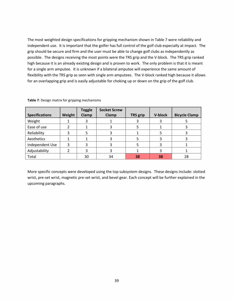
The most weighted design specifications for gripping mechanism shown in Table 7 were reliability and
independent use. It is important that the golfer has full control of the golf club especially at impact. The
grip should be secure and firm and the user must be able to change golf clubs as independently as
possible. The designs receiving the most points were the TRS grip and the V-block. The TRS grip ranked
high because it is an already existing design and is proven to work. The only problem is that it is meant
for a single arm amputee. It is unknown if a bilateral amputee will experience the same amount of
flexibility with the TRS grip as seen with single arm amputees. The V-block ranked high because it allows
for an overlapping grip and is easily adjustable for choking up or down on the grip of the golf club.
Table 7: Design matrix for gripping mechanisms
Specifications Weight Toggle Clamp
Socket Screw Clamp TRS grip V-block Bicycle Clamp
Weight 1 3 1 3 3 5
Ease of use 2 1 3 5 1 3
Reliability 3 5 3 1 5 3
Aesthetics 1 1 3 5 3 3
Independent Use 3 3 3 5 3 1
Adjustability 2 3 3 1 3 1
Total 30 34 38 38 28
More specific concepts were developed using the top subsystem designs. These designs include: slotted
wrist, pre-set wrist, magnetic pre-set wrist, and bevel gear. Each concept will be further explained in the
upcoming paragraphs.

40
Figure 35: Final slotted wrist design using realistic materials.
Slotted Wrist made
from carbon fiber Wrist attachment, arm bar, and
quick release all made from
Aluminum
Top Concepts
Slotted Wrist
The slotted wrist is a completely original idea that was inspired by the need for double arm
amputees to find a way to hinge their wrists during the golf swing. Our final design incorporates
many new features that are additions to our original conceptual design. These additions include
a quick release feature and a redesigned arm bar that provides the user with better control of
the golf club during their swing, show below in Figure 35. The heart and soul of this design is
based around the slotted wrist component. This device allows the user to hinge the club by
contracting their bicep, creating a wrist-like motion that ultimately creates a more natural
looking golf swing for double arm amputees who have minimal to zero wrist function.
Our final design will be manufactured using a variety of different techniques. For example, the
arm bar and wrist attachment of the slotted wrist will be machined using a CNC HAAS mill and
will made from aluminum. In contrast, the slotted wrist will be made from carbon fiber using a
hand layup process, where layers of carbon fiber will be molded along outside of a positive
mold shaped like the internal cavity of the slotted wrist, shown in Figure 36. The final
component of our design, the quick release, will be purchased online

41
Slotted Wrist: Mimics the
function of the wrist in the golf
swing, but accomplishes this
movement through the user
contracting their bicep.
Arm Bar: connects the
slotted wrist to the wrist
attachment
Quick Release: allows the
slotted wrist to be
adjusted into different
positions
Prosthetic Hook: used by the
majority of double and single
arm amputees.
Wrist Attachment: attaches
to the users prosthetic and
allows them to control the
slotted wrist
Prosthetic Arm: serves as
a basic representation of
the prosthetic arm that
many amputees use
Figure 36: Fully assembled slotted wrist design which incorporates a resigned arm bar, quick
release, and wrist attachment, providing complete control of the golf club for the user.
(http://www.everybicycletire.com/shopping/pc-1693-165-american-classic-titanium-quick-release-
skewers.aspx) and then welded to the wrist attachment.

42
Pre-set Wrist
The idea of the Pre-set Wrist came from the same need to find a way for a double arm amputee to hinge
their wrists during the golf swing in order to maximize the force at impact with the golf ball and the golf
club face. This is accomplished in the Pre-set Wrist design by hinging the wrist ahead of time prior to
starting the backswing. This idea was derived from a golf drill that many instructors use to teach
amateurs and professionals how to feel the proper wrist hinge during the take away and backswing.
The Pre-set Wrist design is made from mostly aluminum components, where the lever and TRS grip are
made from a polyurethane material and the ball and sock joint is made from stainless steel. The slotted
wrist attaches directly to the butt end of the golf club. The TRS grip attaches in the same manor
discussed in the slotted wrist design, and secures the club through friction generated between the TRS
grip and golf grip. In this design a slot and pin mechanism is used, with a designed lock and unlocking
feature that hinges the wrist into the appropriate position with the application of an upward applied
force (Fig. 37). The wrist will stay hinged in this position until an equal but opposite downward force is
applied to the locking mechanism. This force will be exerted on the down swing by the extension of the
right arm, unhinging and unlocking the wrist from its pre-set position just prior to impact, allowing the
club to strike the golf ball. A 3-D model of this design is located in Appendix E.
B.
C. A.
Figure 37: Complete Pre-set Wrist design including both forearm plates, TRS Grip, Ball and socket joint, hinge, and threaded
attachments (A). The hinge mechanism uses a locking system that orients the club at 0 and 60 degrees (B)(C).
Threaded
Attachments Direction of applied
force

43
Magnetic Pre-set Wrist
Figures 38 and 39 below show the magnetic wrist design. This design uses a magnet to hinge and
release the wrists during the golf swing. There will be a compartment located on the prosthetic that will
have a microprocessor and an accelerometer that controls the strength of the magnet. The
accelerometer will detect the accelerations produced during the golf swing. When the club accelerates,
current will be sent through the magnet, making it magnetize. The more current that goes through the
magnet, the stronger it will be. This will allow the wrists to hinge as the back swing is made. When the
swing starts to return to the neutral position, the magnet will release the club and then another magnet
will catch the club on the follow through. This design will require a lot of analysis of a golfer’s swing to
figure out the placement of the magnets and the strength of the magnets. The grips on all shafts will
have to be removed and altered so that the shaft can be directly attached to a ball and socket joint on
the prosthetic.
Figure 38: Front view of golfer using magnetic design Figure 39: Close-up front view of magnetic design

44
Bevel Gear
The bevel gear design idea originated from the golf swing robot arm, also known as the Iron Byron, seen
below in Figure 41. The basic concept of the Iron Byron involves a bevel gear system that is attached to a
golf club. The arm is powered by a motor that initiates rotation for the backswing. During the backswing
the club is able to rotate laterally and radially due to the freedom the bevel gear allows. The club locks in
position at the top of the backswing due to a lever that is caught by a hook under the robotic arm. Once
the club starts the downswing a solenoid releases the hook’s grip allowing the club to swing completely
through the ball.
The bevel gear design idea for the golf prosthesis uses the basic concepts from the Iron Byron. The main
difference between the two is that the Iron Byron simulates both arms swinging a golf club while the
bevel gear design is only designed for one arm. The bevel gear system is attached to the end of the right
arm which allows rotation in the backswing. The bevel gear system attaches to the grip of the golf club
using a TRS Eagle grip. Similarly, the left arm uses a TRS Eagle Golf TD grip that attaches to the grip of
the golf club. Since the TRS grips are made of polyurethane they have a substantial amount of flexibility
that assists in the rotation of the golf club.
Figure 40: Layout drawings of bevel gear design Figure 41: Golf swing robot arm (Iron Byron)

45
Specification Satisfaction for Top Concepts
In order to determine which concept will be selected as our final design we looked at each one to see
how well they satisfy the customer specifications. Earlier in the design process we looked at how well
our concepts satisfied the design specifications in order to select our top concepts. Now that we have
narrowed our choices down to four top concepts we must look closer at each design and determine how
feasible their construction will be.
Our first specification is price. Since we do not have a bill of materials for any of the top concepts we
cannot pinpoint the final cost for each. But we can roughly estimate the cost based on how many parts
will be needed. Both the slotted wrist and pre-set wrist designs are cheaper when compared to the
bevel gear and magnetic designs. They are cheaper because they do not require moving parts where
both the bevel gear and magnetic designs do require moving parts.
When it comes to weight the golfer wants the device to be as light as possible. With this in mind all of
the top concepts are relatively lightweight except the bevel gear system. The bevel gear has numerous
moving parts in order to assist rotation during the backswing. The extra weight of all the parts is
detrimental to the golf swing and makes the entire swinging process more difficult for the golfer.
Ease of use, interchangeability, reliability, and independent use are specifications to be determined by
the golfer when using the device. All four of our top concepts have been designed to meet each of these
specifications but it is difficult right now to determine which design will meet these specifications the
easiest. The only way to determine this will be to test our concepts.
The final specification is the aesthetics of the device, or how appealing the device is to look at. Since
each concept is essentially a swing aide they would look abnormal if you saw someone use one on a golf
course. With this in mind the final design must look as ordinary as possible. Immediately both the bevel
gear system and magnetic designs stick out like a sore thumb. Both systems have numerous moving
parts that take away from the golfer actually swinging the golf club with their given skill set. Also, the
bevel gear system is bulky and looks out of place on a golf course. The pre-setting wrist isn’t bulky but
the fact that you have to cock your wrists in place before you start your backswing may leave golfers
self-conscious when playing. The slotted wrist design has the least moving parts and isn’t bulky enough
to attract unwanted attention.
After reviewing how well our four top concepts meet the design specifications, we narrowed down our
selection to the slotted wrist and pre-setting wrist designs. These two designs, once manufactured, are
smaller and lighter making it easier for an amputee to use. They also involve less moving parts than the
bevel gear system and magnetic designs. We want to move forward with a simplistic design in order to
manage production cost and future maintenance of the device. Solid Works models of the slotted wrist
and pre-setting wrist designs are shown in Appendix E.

44
B.1: Initial Slotted Wrist Solidworks Model
Figure 42: Slotted Wrist Solid works Model

45
B.2: Golf sleeve drawings

46
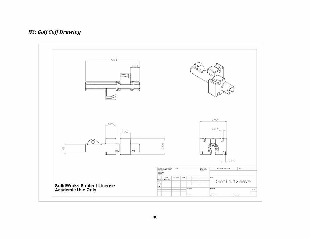
46
B3: Golf Cuff Drawing

47
B.4: Hook drawings

48

48
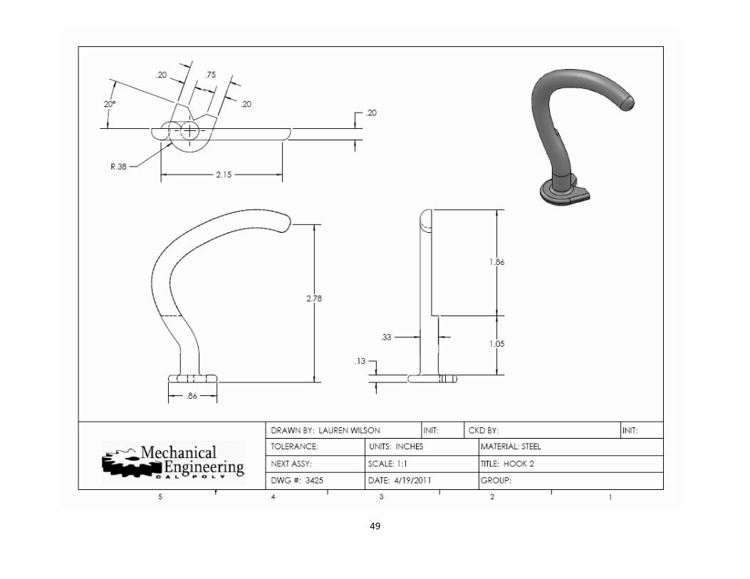
49

50

51
B.5: Final Slotted Wrist Drawings

52

53

54

55

56
B.6 Forearm Attachment Solid works Model

57

58
B.7 Preset Wrist Solid works Design
Stage 1: Before Pre-setting Stage 2: Pre-setting Stage 3: Release of the club

59

60
C.Gantt Chart
Winter Quarter 2011
Project Name ID Comments Who's responsible Days Start End 18-Jan 25-Jan 1-Feb 8-Feb 15-Feb 22-Feb 1-Mar 8-Mar 15-Mar 22-Mar
Golf Prosthesis:
Winter/Spring/Fall 2011 1.0 56 11-Jan 8-Mar
Problem Definition Phase 1.1 20 11-Jan 31-Jan
Define objectives 1.1.1 7 11-Jan 18-Jan
Define requirements 1.1.2 7 11-Jan 18-Jan
Put together background info 1.1.3 7 11-Jan 18-Jan
Layout responsibilities of members 1.1.4 7 11-Jan 18-Jan
Develop QFD 1.1.5 4 27-Jan 31-Jan
Report 1.1.6 Report due on Jan 31 4 27-Jan 31-Jan
Concept Design Phase 1.2 35 1-Feb 8-Mar
Idea Generation/Design Matrix 1.2.1 7 1-Feb 8-Feb
Conceptual Model 1.2.2 Due Feb 14 4 10-Feb 14-Feb
Sketches 1.2.3 7 10-Feb 17-Feb
Choose Final Design 1.2.4 Due Tuesday, Feb. 22 8 14-Feb 22-Feb
Analysis of picked design 1.2.5 7 15-Feb 22-Feb
Report 1.2.6 Report due on Feb 28 21 15-Feb 8-Mar
Prepare Presentation 1.2.7 Review on Mar 8 21 15-Feb 8-Mar
Design Phase 1.3
Critical Design Review 1.3.1 21 28-Mar 18-Apr
Build Product/System 1.3.2 39 25-Apr 3-Jun
Status Report to Sponsor 1.3.3 14 20-May 3-Jun
System Testing/Iterating 1.4 70 20-Sep 29-Nov
Final Report 1.4.1 70 20-Sep 29-Nov
Senior Design Expo 1.4.2 0 29-Nov 29-Nov
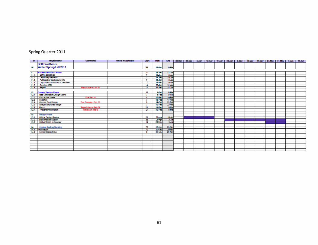
61
Spring Quarter 2011

62
Fall Quarter 2011