Embed Size (px)
Citation preview

2011-2012

Table of Contents
Irrigation Services 3
NSN® (National Support Network) 4
Control Systems and Field Controllers
Lynx™ Central Control 5
ITT Flowtronex® Pump Stations 6
Turf Guard® Soil Monitoring System 7
SitePro® Central Control 8
PRISM™ & T.Weather® 9
Hand-held Radio Interface 10
Network Radio Link and FIU with Radio 10
Network VP® Satellites 11
E-OSMAC®, OSMAC RDR Satellites 12
Network LTC® Plus Satellites 13
GDC Two-Wire System 14-15
Sprinklers/Drip
Comparison Charts 16-17
835S/855S Series Rotors 18-19
834S/854S Series Rotors 20-21
DT35/DT55 Series Rotors 22-23
DT34/DT54 Series Rotors 24-25
B Series Rotors 26-27
Mainless and Back Nozzle Data 28
Toro® Conversion Assemblies 29
R-Series Conversion Assemblies 30-31
810G Series Rotors 32-33
810GL Series Rotors 32-33
720/720G Series Rotors 34
640 Series Rotors 35
690 Series Rotors 36
Toro® Swing Joints 37
590GF Sprays 38
DL2000® Subsurface Drip 39
Precision™ Series Spray Nozzles 40-41
Precision™ Series Rotating Nozzles 42
Sprinkler Tools 43
Valves
Comparison Chart 44
220G Brass Series 45
P-220G Series 46
P-220GS Scrubber Series 47
Quick Couplers 48
Resources
Technical Data 49
Wire Sizing 50
Warranty 51
Distribution 52
2

3
Irrigation Services
Toro Technical SupportOur technical support team is highly skilled at what they do. From helping superintendents, program controllers, to troubleshooting complex system issues with consultants, the support team provides years of irrigation experience that you can count on. For exceptional technical support, call 1-877-345-TORO.
Toro Controller RepairDid you know that with Toro’s Board Exchange Program you can get the replacement controller boards you need immediately? Through your distributor, Controller Repair provides controller boards ready for immediate board exchange to assure that controller downtime is minimal and your golf course and reputation stays protected. For immediate assistance call: 1-877-345-TORO.
Toro Field ServiceWith some of the most knowledgeable and helpful field service staff in the industry, and our extensive training and support programs; Toro field service personnel are always there to assist—before, during, and well after a sale.
Toro Genuine PartsFrom the smallest sprinkler part to complete control systems, Toro Service Parts support can deliver most replacement parts to our distributors within hours. In fact, Toro offers its customers the highest parts order completion rate in the industry: 98%!
Toro FinancingBy offering a variety of customized, competitive financing plans, Toro gives you “one-stop shopping” eliminating the need for third-party funding. You can improve your course without draining your budget.
www.toro.com/golfLog onto www.toro.com/golf for more information about our products and services.

4
Features
• Remote access so that you can control Irrigation anytime, anywhere• Easy access from your Apple or Windows mobile device• Ability to easily transfer files• Ability to print remote documents from a remote location• Remote access activity logs and other security features
Features
• Adds remote hardware and software monitoring to NSN Connect• Automatic notifications via Email and Txt• Proactive support and computer hardware replacement from NSN• Ability to chat with NSN support staff
Minimum Requirements for Remote Control Devices
• Desktop or Laptop - Windows 7 or XP - Internet Explorer 5.0 or higher• Apple Mobile Device - iPhone, iPod Touch, or iPad - iOS 3.0 or higher - NSN Connect app from the iTunes App Store• Windows Mobile Device - Windows Mobile 5.x, 6.0, or 6.1.x - Mobile Internet Explorer - Touch screen
NSN® Connect Plus
Specifications
• Platform – Toro® Lynx™ control system• Operating System – Windows 7 (64-bit)• User Configuration - Ability to have multiple email/txt recipients for alert notifications - Ability to set a schedule (days and times) of when to receive alert notifications - Ability to enable / disable specific monitors - Ability to have alerts sent to different recipients for different monitors• Monitors - Toro Lynx Control System Software• Errors / Issues• Status - Computer Hardware• Health• Status• High speed Internet access required at the Irrigation computer• NSN Chat capability integrated into the NSN Button of the Toro Lynx control system
NSN® Connect
An Unparalleled Range Of Support Service SolutionsAt Toro, our top priority is providing you with the best golf irrigation products and then backing them with superior service and support. To keep you and your course on track, our comprehensive service offerings range from installation and training to system optimization, and everything in between. We understand your reputation is on the line every day and we pledge to provide a levelof support that ensures your success, with every Toro product, every day.
NSN® (National Support Network)-We’re Always Here For You
Features
• Control system repair and refinement provides more precise watering.• Site code setup for micro-managed irrigation.• Nozzle database and hydraulic system repair and refinement provide greater operational flexibility and reduced system wear and tear.• TZF file compression & cleaning and multiple database creation provide specialized programming to meet specific site requirements.
NSN® Custom Database Management
Irrigation Services

5
Lynx™ Central Control System
Features
• Area and Hole orientation allows you to control your irrigation system the same way you think about the course• Runtimes are executed to the second rather than rounding to the whole minute, resulting in more precise irrigation and water savings• Dynamic Drilldown enables area, hole or station views in Watering Plan and Course Report screens• Course Report provides both real time and daily summaries of both scheduled and manual watering events. Take the guesswork out of knowing how your system performed• Control your irrigation by setting runtime minutes or application inches and let the system calculate the other. See exactly how much water you will apply and how long you will irrigate each area.• Turf Guard integration helps you determine when to irrigate and how much• Create and edit your own interactive digital map.• Fully supports CAD-generated maps• Integrated run time display shows past and planned irrigation activity so you can easily determine what action to take.• With Quick Setup, you create station, hardware and area associations, and control the definition of greens, tees, fairways and sprinklers based on their locations.• A basic hydraulic tree is auto-generated for you during Quick Setup.• Instant Program has simple check-box selection and Dynamic Drilldown so you can instantly create and personalize new irrigation programs.• Projected Flow view shows you areas that will be watered and how much will be applied.• Integration with an ITT Flowtronex® pump station enables the exclusive Lynx Power Guard feature to track and controlelectricity usage of the system.
Features (continued)
• Pump station monitoring helps ensure sprinkler performance and prevent wasted water or energy.• Runtime synchronization with Network VP satellites prevents irrigation outages if the central goes offline.• Current-sensing capabilities notify you of wire cuts and sprinklers unintentionally turned off.• Constant communication with Network VP® satellites lets you take action if a power outage threatens irrigation.• GDC communication and solenoid diagnostics help identify shorts, low voltage and other issues.• Weather station integration and Hand-held Remote Interface support are included as standard features
Specifications
• Maximum satellites: 500• Maximum satellite stations: 32,000• Maximum GDC control units: 4000• Maximum GDC stations: 6400• Map Interface: Standard• Hand-held Radio Interface: Standard*• Weather Software: Standard*• Pump Station Integration: Standard*• Turf Guard Soil Sensor Integration: Standard*• Flow / Pressure / Temperature / Status Sensor Monitoring: Standard*• Communication modes: Wireless digital paging; 2-way wireline; 2-way wireless; Hybrid• Operating System: Windows 7• Platforms supported: Network VP, E-OSMAC, OSMAC-RDR, GDC
Warranty
• 1 or 5 Years Renewable NSN Support
Specifying Information—Lynx Central
LX-0X-X-0XComputer Hardware Service Field Hardware
0X X 0X
1—Standard Computer4—Premium Computer
1—1-year NSN5—5-years NSN
01—For OSMAC07—For Network VP08—For Network GDC
Example: When ordering a LYNX Central standard computer with one year of NSN and Network VP field hardware, you would order: LX-01-1-07

6
FlowNet Service - the largest most experienced service network in the golf course pump station industry. Sixty-five field offices with over 200 Certified FlowNet technicians. 24/7/365 customer support available at 1-800-786-7480.
NEW Silent Storm SSC Specifications
• Compact Modular Design• Available in 4 to 6 weeks• Flow Rates from 200-4300 gpm**• Pressures from 50-150 psi**** Other flows and pressures available
Silent Storm Vertical and Horizontal Specifications
• Toro central control ready with dynamic interaction• NEMA 4 enclosure provides optimum weather resistance for vital electrical components• Color touch screen menu-driven and easy to use, web-empowered control touch screen displays key station operational data• Smoothflow VII proven on thousands of pump stations, seventh generation control software is powerful & user-friendly• Web-enabled monitoring and control software allows remote access from almost anywhere.• cUL and UL listed for US and Canada• Fused disconnect 65kA rating provides extra protection for equipment and personnel• Protective coating direct-to-metal process with 3-year warranty ensures long-life station protective coating• Continuous uninterrupted weld around deck plate minimizes station corrosion• Wafer-style check valves• Integral Wetwell cover with built-in hinged panels provide easy access & ensure safety around the skid• Claval relief valve with inlet isolation valve provides proper hydraulic control in the event of drive failure• 1” Pump plate prevents deflection & adds life to the pumps & the station• Superior construction techniques ensure a long service life• UL listed as a packaged pump system• High discharge pressure safety• S.L.A.P. (Surge & Lightning Advanced Protection)• Solid state overload for phase imbalance, low voltage, and overload protection• Low discharge pressure with manual override• Suction & discharge “Z” Pipe• Lake level controls• Flowmeters available in mechanical or digital
FloBoy Series Specifications
• Flow rates up to 450 gpm**• Pressures from 50-150 psi**** Other flows and pressures available
Nutrifeed Features
• Rigid chemical resistant base• Neptune adjustable diaphragm metering pumps - 12.5, 30, and 85 GPH capacity• Corrosion-resistant control enclosure, NEMA 4X rated• High pressure braided PVC flexible hose for suction & discharge• Polypropylene fittings, impervious to all known irrigation chemicals• 316 SS wetted components are standard in 12.5 & 30 GPH pumps• PTFE diaphragm• Built-in externally adjustable pressure relief valve• Up to 3 pumps any combination can be operated at once
ITT Flowtronex® Pump Stations
7
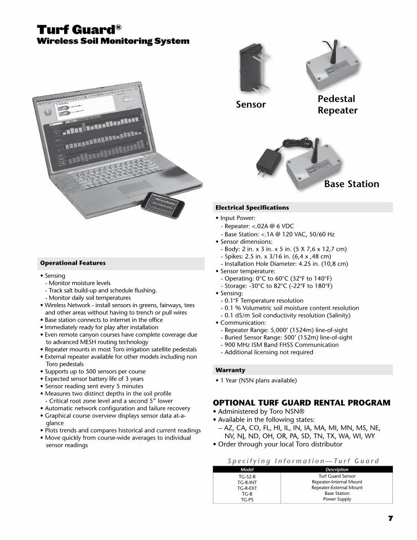
Turf Guard®
Wireless Soil Monitoring System
S p e c i f y i n g I n f o r m a t i o n — Tu r f G u a r dModel Description
TG-S2-RTG-R-INTTG-R-EXT
TG-BTG-PS
Turf Guard SensorRepeater-Internal MountRepeater-External Mount
Base StationPower Supply
Operational Features
• Sensing - Monitor moisture levels - Track salt build-up and schedule flushing. - Monitor daily soil temperatures• Wireless Network - install sensors in greens, fairways, tees and other areas without having to trench or pull wires• Base station connects to internet in the office• Immediately ready for play after installation• Even remote canyon courses have complete coverage due
to advanced MESH routing technology• Repeater mounts in most Toro irrigation satellite pedestals • External repeater available for other models including non
Toro pedestals• Supports up to 500 sensors per course• Expected sensor battery life of 3 years• Sensor reading sent every 5 minutes• Measures two distinct depths in the soil profile - Critical root zone level and a second 5” lower• Automatic network configuration and failure recovery• Graphical course overview displays sensor data at-a-
glance• Plots trends and compares historical and current readings• Move quickly from course-wide averages to individual
sensor readings
Sensor Pedestal Repeater
Base Station
Warranty
• 1 Year (NSN plans available)
OPTIONAL TURF GUARD RENTAL PROGRAM• Administered by Toro NSN®• Available in the following states: – AZ, CA, CO, FL, HI, IL, IN, IA, MA, MI, MN, MS, NE, NV, NJ, ND, OH, OR, PA, SD, TN, TX, WA, WI, WY • Order through your local Toro distributor
Electrical Specifications
• Input Power: - Repeater: <.02A @ 6 VDC - Base Station: <.1A @ 120 VAC, 50/60 Hz• Sensor dimensions: - Body: 2 in. x 3 in. x 5 in. (5 X 7,6 x 12,7 cm) - Spikes: 2.5 in. x 3/16 in. (6,4 x ,48 cm) - Installation Hole Diameter: 4.25 in. (10,8 cm)• Sensor temperature: - Operating: 0°C to 60°C (32°F to 140°F) - Storage: -30°C to 82°C (-22°F to 180°F)• Sensing: - 0.1°F Temperature resolution - 0.1 % Volumetric soil moisture content resolution - 0.1 dS/m Soil conductivity resolution (Salinity) • Communication: - Repeater Range: 5,000’ (1524m) line-of-sight - Buried Sensor Range: 500’ (152m) line-of-sight - 900 MHz ISM Band FHSS Communication - Additional licensing not required

8
SitePro® Central Control System
S p e c i f y i n g I n f o r m a t i o n — S i t e P r oSP-0X-X-0X-NB
Type Computer Hardware Service Field Hardware Optional
SP 0X X 0X NB
SP—SitePro 1—Standard Computer4—Premium Computer
1—1-year NSN5—5-years NSN
3—Network LTC Plus NB—Narrow-band Digital Wireless Paging
Example: When specifying a SitePro Central standard computer with one year of NSN and Network LTC Plus field hardware, you would specify: SP-01-1-03
Optional Features
• T.Weather® WeatherLogic® software module which allows: − Calculated ET-driven runtimes – User-defined alarm thresholds – Interactive, automatic response to the central• NWHH hand-held radio software for on-course irrigation
control• PRISM graphical on-course irrigation control
SitePro 3.0 Network VP Support
• Station base flow management• Station current sensing• Download times reduced by up to 80%• Individual station cancel
Features
• Remote access to your system anytime, anywhere with NSN® Connect.
• Integrate SitePro with your pump station.• Run your system directly from T.Map® to view, edit and create
irrigation programs. Compatible with GPS, CAD and aerial photography.
• Multiple communication modes: – Wireless digital paging – 2-way wireline – 2-way wireless – Hybrid (combination of wireline and wireless) for Network LTC® Plus and Network VP®• Available Alarm/Response capabilities: – Reads sensors from the field – Logs status of sensors based on multiple "if/then" logic to
generate alarms• Automated adjustment factors allow scheduling refinement
from 0-999% by station, satellite, program, group and global• Selectable program upload information• Microsoft® Windows XP Professional™ compatible• User-definable names vs. system defaults• Toro Repeat & Soak assigned by program or station: – Up to 3 repeats per program – Up to 24 starts per program• Advanced multi-manual operations for overseeding, hot spots or
fertilizer wash-in for all hardware platforms• Extensive reporting capabilities
Features (continued)
• Multi-lingual display (English, Spanish, French, German, Italian, Japanese and Chinese)
• Pump station integration – Connect to multple pump stations – Maximize system efficiency and save energy
Warranty
• 1 Year or 5 Year renewable warranty with NSN® support agreement
Specifying Information—SitePro Synergy SeriesModel Number Description
SP-00-1-11-NB SP-00-1-13 SP-00-1-18
SitePro Synergy Series for E-OSMAC and OSMAC RDRSitePro Synergy Series for Network LTC PlusSitePro Synergy Series for GDC

9
T.Weather® with WeatherLogic®
Specifying Information—T.Weather w/WeatherLogic
Model No. Description
997-04 T.Weather w/WeatherLogic Software
Close
SitePro Data
Radio Commands
Percent Adjust/Hold
Utilities
Cancel Current Selection
Soft Keyboard Select
QuickView
Multiple Sprinkler Select
Accept Current Selection
PRISM™ Mobile Control
Specifying Information—PRISM Software Order No. Description
676-17 676-18 676-19
676-26* 676-27* 676-28*
Bundles with iPAQ PDA PRISM Software, iPAQ Unit, 1 Year NSN Support (1st Unit) PRISM Software, iPAQ Unit, 1 Year NSN Support (2nd Unit) PRISM Software, iPAQ Unit, 1 Year NSN Support (Units 3–5)
Software Only* (with NSN) for iPAQ 3800 PRISM Software, 1 Year NSN Support (1st Unit) PRISM Software, 1 Year NSN Support (2nd Unit) PRISM Software, 1 Year NSN Support (Units 3–5)
*Only available to customers who have purchased an iPAQ through Toro NSN
Features
• Manually start stations, change station percent adjustments or put selected sprinklers on hold
• Review and adjust system settings• PRISM desktop software allows you to download all changes
to update your SitePro system• View greens, tees, fairways, etc.• Select holes and sprinklers• With the QuickView™ feature, use PRISM before you have
a map—it converts SitePro® data into a grid view with a station summary display
• Send radio commands (with repeat functions)• Save and recall up to 20 user-defined commands• Modify hold times by utilizing a pop-up calendar• One-year NSN® toll-free telephone support• Voice recorder, mobile address book and calendar capability• Works exclusively with Toro SitePro®, Network CDS,
Network LTC® Plus, Network DR2™, Network 8000®, Network VP® and GDC in conjunction with the Hand-Held remote system, and SitePro for E-OSMAC®
Features
• Provides control of on-site or off-site weather stations: - Phone - Radio - Wireline• User-defined polling interval• Color-coded alerts indicate when environmental
conditions are not within the normal range• Interactive, automatic response to the SitePro central control
system• Weather station data (temperature, relative humidity,
dew point, wind speed and direction) displays in real time or 24-hour periods:
- 24-hour periods show high, low and average data• Solar radiation displays daily total• Data totals for ET, rain and the difference between them
shown for the last hour, 24 hours, 7 days and 365 days• Stores weather station data for up to one year• System displays time in 12-hour (a.m./p.m.) or 24-hour
format• Defines specific conditions for alarms using multiple inputs• Pause irrigation cycles according to the user-defined alarm
thresholds• Transmits the changes in alarm conditions to SitePro so
it can resume irrigation again• Weather tracking allows viewing of current data retrieved
from the weather stations, or creating reports based on the past hour, day, week or year

10
Hand-held Radio Interface
Network Radio-Link and FIU with Radio
Specifying Information—Network Hand-held Software
Model Number Description
997-05 Network Hand-held SoftwareNote: FCC license required.
Specifying Information—Hand-held Radio InterfaceNB-HHRI-0X
Communication Hardware Optional
NB HHRI 0X
NB—Narrow Band HHRI—Hand-held Radio Interface 01—With Radio 02—Less Radio
Example: When specifying a Network Hand-held radio with narrow-band frequency and a 110 V ac transformer, you would specify: NB-HHRI-01
Note: FCC license required.
Specifying Information—Field Interface Unit (FIU) Model No. Description
FIU-2010 FIU-2011 FIU-2011R FIU-2020 FIU-2021 FIU-2021R
Field Interface Unit with 1 Wire Line Field Interface Unit with 1 Wire Line and 1 Radio Line, Radio Not Included Field Interface Unit with 1 Wire Line and 1 Radio Line, Radio Included Field Interface Unit with 2 Wire Lines Field Interface Unit with 2 Wire Lines and 1 Radio Line, Radio Not Included Field Interface Unit with 2 Wire Lines and 1 Radio Line, Radio Included
Note: FCC license required.
Features
• Wireless communication to Network satellites• Network Radio-Link kits for upgrades• True 2-way communication• Multi-port field interface allows one radio to be shared
among many satellites• Easy satellite installation• Compatible with Network LTC Plus and Network VP
Features
• Optional for the following Lynx™ central control systems: - Network VP - OSMAC - GDC• Optional for the following SitePro® Network central control
systems: - Network VP® - Network 8000® - Network LTC® Plus - Network CDS - Network DR2 - GDC• Access central and satellite features from the field.• Clear audio verification of system commands.• Simple command set• Extensive start and syringe capabilities• Comprehensive multi-manual functionality• System and program pause and resume• System On and Off command activation• Built-in programmable radio• UL listed
11
Dimensions
• Plastic Cabinet: 17” W x 40” H x 16” D (41cm W x 99cm H x 41cm D)• Metal Cabinet: 13” W x 36” H x 13” D (33cm W x 91cm H x 33cm D)
Additional Specifications
• Operating temperature: -10°C to 60°C (15°F to 140°F)• Storage temperature: -30°C to 65°C (-22°F to 149°F)• Humidity: 0% to 95% RH (non-condensing)
Features
• Station based flow management reduces nighttime water window and optimizes pump capacity.• Variable Length (VL) communication reduces download time by up to 80%.• Current sensing monitors each station output for proper amperage draw with user defined thresholds.• Intuitive user interface with backlit display for better low-light viewing.• Optional output switches and surge protection• Multi-Manual, Program Start and Syringe manual operations• Group Multi-Manual operation• Sturdy plastic or painted stainless steel pedestals• Operates as a stand-alone controller, or under the management of a central computer - Supports wireline or radio communications - Supports hybrid communication (wireline and radio) for increased flexibility and cost effectiveness.• 64 irrigation programs: independent stand-alone and central operation• Basic, Advanced and Grow-in programs • Pause, Resume and Stop functions• Supports run times from 1 second to 23 hours, 59 minutes, 59 seconds• Percent adjust from 1% to 900% (Station, Program, Satellite)
Features (continued)
• Each output can be defined as an irrigation station or general application switch• Non-volatile memory retains program information and satellite settings during power-off conditions. Battery back-up retains the satellite date and time • 16-64 stations in 8-station increments – 64 programs – individual station control and the ability to run up to 32 stations simultaneously• Backwards compatible with Network 8000 satellites.
Electrical Specifications
Input Power:• 108 V ac to 132 V ac, 60 Hz - 0.20 amps (no load) 115 V ac - 1.20 amps (max load) 115 V ac• 216 V ac to 264 V ac, 50 Hz - 0.10 amps (no load) 230 V ac - 0.60 amps (max load) 230 V acOutput Power:• 24 V ac - 3.0 amps (max total load)• UL Listed
Specifying Information—Network VP Satellites201-XX-X-6-X-X
Description Configuration Cabinet Output Comm. Options
201 XX X 6 X X
201—Network VP Satellite
16—16 Stations 24—24 Stations32—32 Stations 40—40 Stations48—48 Stations 56—56 Stations64—64 Stations
P—Plastic, GreenS—Stainless Steel (Painted)T—Desert SandB—Tree Bark
6—24 VAC Electric A—Stand-aloneM—2-Way Wire ModemR—UHF Radio
0—No Options1—Large-capacity Terminal Block w/Standard Surge2—Large-capacity Terminal Block w/Add’l Surge3—Large-capacity Terminal Block & Switches4—Large-capacity Terminal Block w/Add’l Surge & Switches
Example: When ordering a 24-station, Stand-alone VP Satellite in a plastic cabinet with large-capacity terminal block, additional surge and switches, you would specify: 201-24P6A4
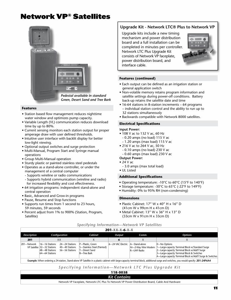
Network VP® Satellites
Pedestal available in standard Green, Desert Sand and Tree Bark
Upgrade kits include a new timing mechanism and power distribution board and a full installation can be completed in minutes per controller. Network LTC Plus Upgrade Kit consists of Network VP faceplate, power distribution board, and interface cable.
Upgrade Kit - Network LTC® Plus to Network VP
S p e c i f y i n g I n f o r m a t i o n — N e t w o r k LT C P l u s U p g r a d e K i t118-0038
Kit Contains Network VP Faceplate, Network LTC Plus To Network VP Power Distribution Board, Cable And Hardware

12
E-OSMAC® and OSMAC RDR Satellites
Dimensions
• Plastic Cabinet: 17” W x 40” H x 16” D• Metal Cabinet: 13” W x 36” H x 13” D• OSMAC RDR Large pedestal: 16’ W x 45 ½” H x 16” D
Optional Accessories
• Wide-band frequency modules (N1551XX) for E-OSMAC or OSMAC RDR• Low-voltage Retrofit Kit – (RDR0160LVN0) for OSMAC RDR
Features-E-OSMAC
• Up to 64 stations• Synthesized decoder modules that can be reprogrammed in the field - new frequency models can store up to 4 pre-programmed frequencies to transition from construction to permanent frequencies (narrow band)• Stainless steel (painted) and bi-wall plastic cabinet configurations• Five terminal strip options available• Colored LED indicators to confirm 24, 9-, and 5-volt power to various boards within the cabinet• LED’s for each station output• Simple self-testing by sliding a switch - more than eight separate functions can be verified. • Internal antenna allows for smaller profile cabinet• Uses automotive fuses• Patented Hot Post for each eight-station module• Mounts to many existing pedestal bolt patterns.
Electrical Specifications
• Input power: 120/240 V ac, 50/60 Hz - E-OSMAC û 0.20 amps, 110-120 V ac, 60 Hz (no load) û 0.96 amps, 110-120 V ac, 60 Hz (max load) û 0.10 amps, 220-240 V ac, 50/60 Hz (no load) û 0.47 amps, 220-240 V ac, 50/60 Hz (max load) - OSMAC RDR û 0.17 amps @ 115 V ac, 60 Hz (no load) û 0.76 amps @ 115 V ac, 60 Hz (max load) û 0.09 amps @ 230 V ac, 50 Hz (no load) û 0.41 amps @ 230 V ac, 50 Hz (max load)• Station output power: 24 V ac; 3.0 amps (72 VA) total• Enhanced surge protection for lower operating costs• UL and CE approved
Features-OSMAC RDR
• Expandable up to 48 stations in eight-station increments• Hydraulic or electric models available• Runs up to 16 stations simultaneously (from the central or by remote control)• Hand-held radio • Multi-function radio allows control and voice transmissions from the same unit• Programmable syringe time from 30 seconds to 128 minutes in 30-second intervals.• Optional relay card available• Pre-wired satellite pedestal models available without RDR control unit for upgrading existing OSMAC systems
Specifying Information—E-OSMAC SatellitesE-XX-X-6A-X-MX
Description Configuration Cabinet Output Communication Options
E XX X 6A X MX
E—E-OSMAC Satellite
16—16 Stations 24—24 Stations32—32 Stations 40—40 Stations48—48 Stations 56—56 Stations
64—64 Stations
P—Plastic, Green S—Stainless Steel (Painted) T—Desert Sand B—Tree Bark
6A—Electric N—Narrow Band P—Wide Band
0—No Options1—Large-capacity Terminal Block w/Standard Surge2—Large-capacity Terminal Block w/Additional Surge3—Large-capacity Terminal Block & Switches4—Large-capacity Terminal Block w/Additional Surge & Switches
Example: When specifying a 32-station, E-OSMAC Satellite with Wide Band digital wireless paging, a stainless steel cabinet, electric output, additional surge protection and a large-capacity terminal block, you would specify: E-32S6APM2
Note: FCC license required. Frequency modules do not need to be ordered separately.Product shipped with four pre-programmed synthesized frequency modules (462.2125, 462.4375, 467.2125 and 467.4375).
Note: FCC license required.
Specifying Information—OSMAC RDR SatelliteRDR-XX-P-XX-X-XX
Description Configuration Cabinet Output Communication Surge Protection
RDR XX P XX X 0
RDR— OSMAC RDR Satellite
16—16 Stations 24—24 Stations32—32 Stations 40—40 Stations 48—48 Stations
P—Plastic 01—Normally Open Hydraulic6A—24 VAC Electric
P—Wide BandN—Narrow Band
0—No SurgeM4—Full Surge
When specifying a 32-station OSMAC RDR Hydraulic satellite in a plastic cabinet, normally open hydraulic output with narrow-band communication, you would specify: RDR32P01N0
Warranty
• 1 Year
Pedestal available in standard Green, Desert Sand and Tree Bark

13
S p e c i f y i n g I n f o r m a t i o n — N e t w o r k LT C P l u s S a t e l l i t e sLTCP-XX-X-6-X-X
Configuration Stations Cabinet Output Communication Options
LTCP XX X 6 X X
LTCP—Network LTC Plus 16—16 Sta. 24—24 Sta.32—32 Sta. 40—40 Sta.48—48 Sta. 56—56 Sta.
64—64 Sta.
P—Plastic, GreenS—Stainless Steel (Painted)T—Desert SandB—Tree Bark)
6—24 VAC Electric A—Stand-alone M—2-Way Wire ModemR—UHF Radio
0—No Options1—Large-capacity Terminal Block w/Standard Surge2—Large-capacity Terminal Block w/Additional Surge3—Large-capacity Terminal Block & Switches4—Large-capacity Terminal Block w/Additional Surge & Switches
Example: When specifying a 64-station Network LTC Plus Satellite with a plastic cabinet, electric output with a 2-way wire modem and optional large-capacity terminal block, you would specify: LTCP64P6M1
Note: FIUs must be ordered separately.
Features
• Exclusive Toro Flowsafe™ protects flow-managed programs in the event of a central or wireline interruption• Transition from stand-alone to central control after construction is complete• 16 independent programs with up to eight running simultaneously (The Network LTC with Electric-hydraulic converters has 8 independent programs with up to 4 running simultaneously)• Wireless, wireline and hybrid configurations allow you to customize the communication network to meet site specific needs.• 16-64 stations in eight-station increments on the Network LTC Plus. The Electric-hydraulic converter models offer 12 to 24 stations in four-station increments• Standard or large-capacity terminal connections (accepts two 14-guage wires)• Standard or additional surge protection• Manual On/Off station switches (optional)• 14-day calendar or 1- to 29- day Interval scheduling by program• 0 to 3 repeats per program• 0- to 59-minute soak time between repeats• Up to 12 starts per program, per day• Station run times from 1-minute to 8 hours and 59 minutes• Global or independent program adjust at the satellite• Percent adjust by program (10 to 250%)• Syringe %, allows 10 to 99% operating adjustment.• Up to 2 non-irrigation (switch) programs available with central software• Non-volatile memory saves program data for up to 10 years without power• Pump and Common control module with standard surge protection• Manual operation by program (normal or syringe), independent station or multiple stations (up to 6)• Patented Toro Hot Post for easy valve activation and identification• Maximum lightning protection with EHC’s
Dimensions
• Network LTC Plus Plastic Cabinet: 17” W x 40” H x 16” D • Network LTC Plus Stainless Steel (painted): 13” W x 35 3/4” H x 13” D • Network LTC with Electric-hydraulic Converters: 16” W x 39” H x 16” D
Warranty
• 1 Year
Electrical Specifications
• Input power (Network LTC Plus): - 115/230 V ac, 50/60 Hz - 0.183 amps @ 115 V ac, 60 Hz (no load) - 0.872 amps @ 115 V ac, 60 Hz (max load) - 0.100 amps @ 230 V ac, 50 Hz (no load) - 0.50 amps @ 230 V ac, 50 Hz (max load)• Input power (Network LTC with Electric-hydraulic Converters): - 115/230 V ac, 50/60 Hz - 0.15 amps @ 115 V ac, 60 Hz (no load) - 1.09 amps @ 115 V ac, 60 Hz (max load) - 0.15 amps @ 230 V ac, 50 Hz (no load) - 0.59 amps @ 230 V ac, 50 Hz (max load)• Output power: - 24 V ac - 3.15 amps (76 VA) total
Network LTC® Plus Satellites
Pedestal available in standard Green, Desert Sand and Tree Bark

GDC 2-Wire Control System
Lynx™ for GDC
1, 2 and 4-station Decoders
GDC 100/200
S p e c i f y i n g I n f o r m a t i o n — G D C S y s t e mXX-0X-X-0X
Type Computer Hardware Service Field HardwareXX 0X X 0X
LX—LynxSP—SitePro
0— SitePro Synergy1—Standard Computer4—Premium Computer
1—1-year NSN5—5-years NSN
8—GDC System18—GDC Synergy (SitePro only)
Example: A Lynx Central standard computer with 1-year of NSN and GDC System field hardware would be specified as: LX-01-1-08
S p e c i f y i n g I n f o r m a t i o n — S t a n d - a l o n e G a t e w a yDEC-SA-200
Type Communication Sta. CountDEC SA 200
DEC—Decoder SA—Stand-alone 200—200 Stations
Specifying Information—DecoderDEC-ISP-X
Type ConfigurationDEC XX
DEC-ISP—Decoder* 1—1-station 2—2-station4—4-station
Example: A 2-station GDC Decoder would be specified as: DEC-ISP-2
*Refer to sprinkler pages for specifying information on Sprinkler Decoders
Specifications
• Maximum number of wire paths: - 16 per gateway• Maximum stations per gateway: - 200 on stand-alone - 1600 on Lynx™ Central• Maximum stations per system: - 200 on stand-alone - 6400 on Lynx Central• Simultaneous stations per output: - 20 on stand-alone - 100 on Lynx Central• Maximum distance from central to decoder (using 14 gauge wire): 2.6 miles• Maximum distance from decoder to sprinkler (using 14 gauge wire): 400 ft.• Solenoids per output: 2 DCLS-P• Stations per decoder: 1, 2 or 4• Operating temperature: 32°F to 140°F (0°C to 60°C)• Storage temperature: -22°F to 212°F (-30°C to 100°C)
Electrical Specifications
• ISP decoders are rated at 20 KV surge protection—the highest in the industry.• Input Power: - 100 V ac, 50/60 Hz - 120 V ac, 50/60 Hz - 220-240 V ac, 50/60 Hz• Gateway output voltage: 38 V ac max• Gateway output power: 98 VA max• Decoder wiring: 14 gauge
Features
• Connect to Lynx or SitePro® Synergy Control Systems or use it as a stand-alone system with the GDC• Station-based flow management• Lynx™ Central - Mapping capabilities - Remote hand-held operation - Weather station integration - Pump station integration• Enhanced diagnostics - Communication - Electrical shorts/opens - Solenoid check• No holding power required to operate stations• Decoder identification is a unique 6-character address• Non-corrosive lockable wall mount cabinet, indoor/outdoor installation
Warranty
• 1 Year
In addition to our standard GDC decoders, Toro® offers most valve-in-head sprinkler models with an integrated decoder.
14

15
Looped Lateral – reduces overall field wire. Direct connect option with integrated sprinkler-decoder reduces system splices.
Looped Lateral with Multi-Station Decoder – reduces overall field wire and communication wire splices. Provides lower system cost.
Herringbone Lateral – minimizes the quantity of communication wire and critical splices. Allows decoders to be accessed without digging.
System configuration options: One size does not fit all. And one type of control system design is not the best for all applications. Whether it’s lowering system costs, reducing field wire or splices, or providing easy access to system components, the GDC system offers a variety of configuration options to best fit your objectives.

16
Sprinkler Comparison Charts
Model 835S/855S 834S/854S DT35/DT55 DT34/DT54 B Series
Page Number 18-19 20-21 22-23 24-25 26-27
Radius 42’-100’ 52’-99’ 43’-92’ 52’-99’ 42’-95’
Short Radius (mainless) 42’-51’ 34’-50’
Radius Reduction Screw X Optional Optional
Back nozzle Capable X X X X
Inlet size 1” and 1½” NPT, BSP, Acme
1” and 1½” NPT, BSP, Acme
1” and 1½” NPT, BSP, Acme
1” and 1½” NPT, BSP, Acme 1” NPT, BSP, Acme
Flow Range 7.1-61.1 GPM 13.-61.8 GPM 8.2-61.3 GPM 13.0-61.8 GPM 7.1-56.3 GPM
Recommended Operating Pressure
65/100 PSI 65/100 PSI 65/100 PSI 65100 PSI 50/100 PSI
Turf X X X X X
High Wind X X X X X
Decoder Systems X X X X
Normally OpenHydraulic System
X X X X
Spike Guard™ Solenoid X X
Full Circle X X X X X
Part-circle Adjustable X X X
Part-circle Fixed
Part/Full Circle In One 40˚-330˚ and 360˚ 40˚-330˚ and 360˚ 40˚-330˚ and 360˚
Ratcheting Riser X
Check Valve X X X X X
Effluent Water Option X X X X X
Smart-Arc Memory
Below Grade
Trajectory Adjustment 7˚-30˚ 25˚ & 15˚ 25˚ & 15˚ 25˚ & 15˚ 7˚-30˚ / 25˚ & 15˚
Warranty 3 Years/5 Years* 3 Years/5 Years* 3 Years/5 Years* 3 Years/5 Years* 3 Years/5 Years*
*When purchased and installed with Toro Swing Joints.

17
Model 810G 810G “L” 720/720G 640 690 590GF
Page Number 32-33 34 35 36 38
Radius 33’-71’ 20’-47’ 19’-49’ 47’-67’ 87’-108’
Radius Reduction Screw X X X
Inlet size 1” NPT,BSP, Acme
1” NPT,BSP, Acme
3/4” NPT & 1” NPT, BSP, Acme 1” NPT, BSP 1½” NPT 1/2”
Flow Range 6.7-27 GPM 1.0-9.8 GPM .85-11.62 GPM 6.0-25.0 GPM 51.0-82.2 GPM .05-4.5 GPM
Recommended Operating Pressure
40-100 PSI 40-100 PSI See page 28 40-100 PSI 80/100 PSI 20-50 PSI
Turf X X X X X X
Low Pressure X X X X
High Wind X X X
Decoder Systems
Normally OpenHydraulic System
720 Only X X
Spike Guard Solenoid 720 Only
Full Circle X X X X 1 and 2 Speed X
Part-circle Adjustable X X X
Part-circle Fixed X 90˚ and 180˚ X
Part/Full Circle In One X X X X
Stainless Steel Riser X
Check Valve Standard Standard Standard Standard X X
Effluent Water Option X
Smart-Arc Memory X X X
Below Grade X X X X
Trajectory Adjustment 5°-25° 5°-25° 5°-25°
Warr Warranty 3 Years/5 Years* 5 Years* 3 Years/5 Years* 3 Years/5 Years* 3 Years/5 Years* 3 Years

18
835S 855S
Operating Specifications
• Inlet: - 835S: 1” NPT, BSP or ACME - 855S: 1 ½” NPT, BSP or ACME• Radius: - 835S: 42’ – 92’ - 855S: 52’ – 100’• Flow Rate: - 835S: 7.1 – 45.3 GPM - 855S: 13.9 - 61.1 GPM• Precipitation Rates: - 835S: Minimum - .37”/hr; Maximum - .53”/hr - 855S: Minimum - .43”/hr; Maximum - .60”/hr• Pilot Valve: Selectable at 50, 65, 80 and 100 psi• Recommended Operating Pressure Range: 65-100 psi (maximum -150 psi and minimum - 40 psi)• Electric Valve-in-Head Solenoid: 24V ac, 50/60 Hz - Inrush: 60 Hz, 0.12 Amps - Holding: 60 Hz, 0.10 Amps• Trajectory: 24 positions from 7° - 30° in 1° increments• Check-O-Matic maintains up to 37’ elevation
835S/855S Series Dimensions
• Body diameter: - 835S: 6 ½” - 855S: 7 ½” • Body height: - 835S: 10” - 855S: 11 3/8” • Weight: - 835S: 2.98 lbs. - 855S: 3.70 lbs. • Pop-up height to nozzle: 3 ¼”
Nozzle Selection
• 835S has eight nozzle variations (30, 31, 32, 33, 34, 35, 36 and 37)• 855S has nine nozzle variations (51, 52, 53, 54, 55, 56, 57, 58 and 59) • Four in-line nozzles, rotating stream pattern• One back nozzle position• Stator variations: 835S – 3 and 855S – 3
Features
• Trajectory 24 positions from 7 to 30 degrees in 1 degree increments.• Spike-guard solenoid with 20,000 volt lightning rating.• Arc adjustment - 40 - 330 degrees and true full-circle in one.• Ratcheting riser allows adjustment with no disassembly.
Warranty
• Three years• Five years when installed with Toro Swing Joints
835S Conversion Assemblies
Models Description
• 835S-3134
• 835S-3537
• 835S-3134E
• 835S-3537E
835S w/31–34 Nozzles(33 Nozzle Installed)835S w/35–37 Nozzles(35 Nozzle Installed)835S w/31–34 Nozzles(33 Nozzle Installed), Effluent835S w/35–37 Nozzles(35 Nozzle Installed), Effluent
855S Conversion Assemblies—(Ribbed Body)
Models Description
• 855S-5154
• 855S-5558
• 855S-59
• 855S-5154E
• 855S-5558E
• 855S-59E• 102-5011
855S w/51–54 Nozzles(53 Nozzle Installed)855S w/55–58 Nozzles(55 Nozzle Installed)(59 Nozzle installed)855S w/51–54 Nozzles(53 Nozzle Installed), Effluent855S w/55–58 Nozzles(55 Nozzle Installed), Effluent (59 Nozzle installed), Effluent690 Adapter allows you upgrade any 690 with 855S conversions
855S Conversion Assemblies—(Ribless Body)
Models Description
• 855S-5154R
• 855S-5558R
• 855S-59R• 855S-5154RE
• 855S-5558RE
• 855S-59RE
855S w/51–54 Nozzles (53 Nozzle Installed)855S w/55–58 Nozzles (55 Nozzle Installed)(59 Nozzle Installed)855S w/51–54 Nozzles (53 Nozzle Installed), Effluent855S w/55–58 Nozzles (55 Nozzle Installed), Effluent(59 Nozzle installed, Effluent)

19
S p e c i f y i n g I n f o r m a t i o n — 8 3 5 S & 8 5 5 S
8X5S-XX-XXXXXBodyInlet Arc Body
Threads Valve Type Nozzle Pressure Regulation* Optional
8X5S 5 X X X X X XX
3—1" 5—11⁄2" 5—Part-circle and Full-circle in one
0—NPT 4—ACME 5—BSP
1—Normally Open Hydraulic2—Check-O-Matic 6—Electric
835S—30, 31, 32, 33, 34, 35, 36, 37855S—51, 52, 53, 54, 55, 56, 57, 58, 59
6—65 psi8—80 psi1—100 psi
E—EffluentDL—DC Latching SolenoidN—Nickel-platedI—Integrated GDC
Example: When specifying an 835S Series Sprinkler with NPT threads, #34 nozzle, an electric valve and pressure regulation at 65 psi you would specify: 835S–06–346
* Electric models only. All sprinklers are equipped with the selectable pilot valve that allows settings at 50, 65, 80 and 100 psi.Note: Not all models available. Nickel-plated, corrosion-resistant models are available upon request.
Nozzle/PSI/GPM #34/54 Nozzle @ 65 psi #35/55 Nozzle @ 65 psi #36/56 Nozzle @ 80 psi
Trajectory 7° 10° 15° 20° 25° 30° 7° 10° 15° 20° 25° 30° 7° 10° 15° 20° 25° 30°
"A" Radius 58' 60' 63' 67' 74' 70' 59' 61'/62' 64'/66' 70' 76' 74'/77' 64'/72' 68'/73' 76'/75' 80'/82' 84'/85' 82'
"B" Spray Height 4'/5' 4'/6' 6'/8' 11'/10' 14' 17' 4'/6' 5'/6' 7'/9' 11' 15' 17' 5' 7' 9' 14' 17' 22'
"C" Distance from Head 24'/31' 26'/34' 35'/40' 39'/41' 39' 39'/42' 30'/34' 32'/36' 36'/43' 43'/45' 43'/45' 43'/45' 25' 38' 40' 45' 49' 45'
Nozzle/PSI/GPM #37/57 Nozzle @ 80 psi
Trajectory 7° 10° 15° 20° 25° 30°
"A" Radius 65'/72' 69'/74' 78'/77' 82'/83' 86'/89' 84'/85'
"B" Spray Height 5' 7' 9' 14' 18' 22'
"C" Distance from Head 30' 39' 41' 46' 50' 46'
#58 Nozzle @ 80 psi #59 Nozzle @ 80 psi
7° 10° 15° 20° 25° 30° 7° 10° 15° 20° 25° 30°
75' 77' 83' 87' 92' 88' 77' 78' 84' 89' 96' 92'
6' 7' 10' 15' 18' 22' 7' 8' 11' 16' 21' 25'
38' 40' 43' 47' 52' 48' 42' 44' 45' 47' 53' 49'
Information is for reference only. Actual results may vary.
835S Trajectory Performance Nozzle/PSI #31/51 Nozzle @ 65 psi #32/52 Nozzle @ 65 psi #33/53 Nozzle @ 65 psi
Trajectory 7° 10° 15° 20° 25° 30° 7° 10° 15° 20° 25° 30° 7° 10° 15° 20° 25° 30°
"A" Radius 46' 46' 50'/51' 53' 54' 50' 46'/49' 49'/50' 51' 55' 63'/64' 54'/65' 54' 56' 59' 62' 66'/68' 61'
"B" Spray Height 4' 4' 5'/6' 8'/10' 11'/13' 13'/15' 3'/4' 4' 6' 9' 12'/11' 15'/13' 4'/5' 5'/6' 7' 9' 13' 15'
"C" Distance from Head 25'/26' 25'/27' 26'/32' 33'/38' 33'/40' 33'/41' 20'/22' 24'/26' 28'/31' 34'/35' 34' 34'/30' 23'/30' 28'/33' 32' 34'/35' 35'/37' 35'/37'
AC
B
835S Series Performance Chart
BasePressure
Nozzle Set 30 (White)
Nozzle Set 31 (Yellow)
Nozzle Set 32 (Blue)
Nozzle Set 33 (Brown)
Nozzle Set 34 (Orange)
Nozzle Set 35 (Green)
Nozzle Set 36 (Gray)
Nozzle Set 37 (Black)
102-2208 102-4587 102-4588 102-4589 102-0728 102-0729 102-0730 102-4261Blue Gray Blue Gray Red Gray Orange Gray Orange Gray Blue Gray Blue Gray Orange Gray
102-2925 102-2910 102-2925 102-2910 102-2928 102-2910 102-2926 102-2910 102-2926 102-2910 102-2925 102-2910 102-2925 102-2910 102-2926 102-2910
psi Radius GPM Radius GPM Radius GPM Radius GPM Radius GPM Radius GPM Radius GPM Radius GPM50 42 7.1 52 13.7 61 17.1 64 20.2 69 27.4 — — — — — —65 45 8.7 54 15.5 63 20.5 66 22.9 74 30.0 76 32.4 80 34.0 — —80 46 9.6 57 17.0 67 22.6 70 25.3 77 33.2 79 35.8 84 37.5 86 40.8100 48 11.2 59 18.9 72 25.2 74 28.2 80 37.0 84 39.9 88 42.5 92 45.3
Stator 102-6929 Blue 102-1939 Yellow 102-1940 WhiteConversions 835S-3134 835S-3537
855S Series Performance Chart
BasePressure
Nozzle Set 51 (Yellow)
Nozzle Set 52 (Blue)
Nozzle Set 53 (Brown)
Nozzle Set 54 (Orange)
Nozzle Set 55 (Green)
Nozzle Set 56 (Gray)
Nozzle Set 57 (Black)
Nozzle Set 58 (Red)
Nozzle Set 59 (Beige)
102-4587 102-4588 102-4589 102-0728 102-0729 102-0730 102-4261 102-4260 102-4259
Blue Gray Red Gray Orange Gray Orange Gray Blue Gray Blue Gray Orange Gray Blue Gray Blue Gray
102-2925 102-2910 102-2928 102-2910 102-2926 102-2910 102-2926 102-2910 102-2925 102-2910 102-2925 102-2910 102-2926 102-2910 102-2925 102-2910 102-2925 102-2910
psi Radius GPM Radius GPM Radius GPM Radius GPM Radius GPM Radius GPM Radius GPM Radius GPM Radius GPM50 52 13.9 62 17.4 66 20.7 69 28.6 — — — — — — — — — —65 54 15.7 64 20.8 68 23.4 74 31.2 76 33.8 81 35.7 — — — — — —80 57 17.2 68 22.9 72 25.8 77 34.4 79 37.2 85 39.4 89 43.6 92 47.5 96 57.0100 59 19.1 73 25.5 76 28.7 80 38.2 84 41.3 89 43.7 94 48.5 95 51.1 100 61.1
Stator 102-1939 Yellow 102-1940 White 102-1941Conver. 855S-5154 855S-5558 855S-59
■ Not recommended at these pressures. Radius shown in feet. Toro recommends the use of a 11⁄4" swing joint at flows over 25-GPM (95-LPM). Sprinkler radius data collected in Toro’s zero wind test facility per ASAE standard S398.1.
Actual site conditions must be considered when selecting the appropriate nozzle.All sprinklers are equipped with the selectable pilot valve that allows settings at 50, 65, 80 and 100 psi.

20
Dimensions
• Body diameter: - 834S: 6 ½” - 854S: 7 ½” • Body height: - 834S: 10” - 854S: 11 3/8” • Weight: - 834S: 2.98 lbs. - 854S: 3.70 lbs. • Pop-up height to nozzle: 3 ¼”
Operating Specifications
• Inlet: - 834S: 1” NPT, BSP or ACME - 854S: 1 ½” NPT, BSP or ACME• Radius: - 834S: 52’ – 91’ - 854S: 52’ – 99’• Flow Rate: - 834S: 13.0 – 46.9 GPM - 854S: 13.2 - 61.8 GPM• Precipitation Rates: - 834S: Minimum - .33”/hr; Maximum - .55”/hr - 854S: Minimum - .33”/hr; Maximum - .61”/hr• Pilot Valve: Selectable at 50, 65, 80 and 100 psi• Recommended Operating Pressure Range: 65-100 psi (maximum-150 psi and minimum-40 psi)• Electric Valve-in-Head Solenoid: 24V ac, 50/60 Hz - Inrush: 60 Hz, 0.12 Amps - Holding: 60 Hz, 0.10 Amps• Trajectory: 25° or 15°• Check-O-Matic maintains up to 37’ elevation
Nozzle Selection
• 834S has seven nozzle variations (31, 32, 33, 34, 35, 36 and 37)• 854S has nine nozzle variations (51, 52, 53, 54, 55, 56, 57, 58 and 59) • Three opposing nozzles, rotating stream pattern• Two additional front nozzle positions provide maximum flexibility• Stator variations: 834S – 2 and 854S - 3
Features
• Dual Trajectory adjustment on main nozzle - 25 or 15 degrees• Spike-Guard solenoid with 20,000 volt lightning rating.• Constant velocity full circle drive• Radius reduction screw can effectively reduce the sprinkler throw down to 30’
Warranty
• Three years• Five years when installed with Toro Swing Joints
834S Conversion Assemblies
Models Description
• 834S-3134
• 834S-3537
• 834S-3134E
• 834S-3537E
834S w/31–34 Nozzles (33 Nozzle Installed)834S w/35–37 Nozzles (35 Nozzle Installed)834S w/31–34 Nozzles (33 Nozzle Installed), Effluent 834S w/35–37 Nozzles (35 Nozzle Installed), Effluent
854S Conversion Assemblies
Models Description
• 854S-5154
• 854S-5558
• 854S-59 • 854S-5154E
• 854S-5558E
• 854S-59E
• 102-5011
854S w/51–54 Nozzles (53 Nozzle Installed)854S w/55–58 Nozzles (55 Nozzle Installed) 854S w/ 59 Nozzle854S w/51–54 Nozzles (53 Nozzle Installed), Effluent854S w/55–58 Nozzles (55 Nozzle Installed), Effluent854S w/ 59 Nozzle, Effluent690 Adapter allows you to upgrade any 690 with 854S conversions
834S
834S/854S Series
854S
854S Nozzle Apex
Pressure Nozzle Apex at 15˚ Apex at 25°
65 PSI
31/51 6’ @ 51’ 13’ @ 54’32/52 6’ @ 51’ 11’ @ 64’33/53 7’ @ 59’ 13’ @ 68’34/54 8’ @ 63’ 15’ @ 74’35/55 9’ @ 66’ 15’ @ 76’
80 PSI
36/56 8’ @ 75’ 18’ @ 83’37/57 9’ @ 74’ 19’ @ 82’
58 10’ @ 82’ 18’ @ 87’59 11’ @ 81’ 21’ @ 91’

21
S p e c i f y i n g I n f o r m a t i o n — 8 3 4 S & 8 5 4 S
8X4S-XX-XXXXXBodyInlet Arc Body
Threads Valve Type Nozzle Pressure Regulation* Optional
8X4S 4 X X X X X XX3—1" 5—11⁄2" 4—Full
Circle0—NPT 4—ACME 5—BSP
1—Normally Open Hydraulic2—Check-O-Matic 6—Electric
834S—31, 32, 33 , 34, 35, 36, 37854S—51, 52, 53, 54, 55, 56, 57, 58, 59
6—65 psi8—80 psi1—100 psi
E—EffluentDL—DC Latching Solenoid For GDC SystemsN—Nickel-platedI—Integrated GDC Systems
Example: When specifying an 834S Series Sprinkler with NPT threads, #34 nozzle, an electric valve and pressure regulation at 65 psi you would specify: 834S–06–346
* Electric models only. All sprinklers are equipped with the selectable pilot valve that allows settings at 50, 65, 80 and 100 psi.Note: Not all models available. Nickel-plated, corrosion-resistant models are available upon request.
854S Series Performance Chart—25°
FrontNozzle
Positions
Nozzle Set 51 (Yellow)
Nozzle Set 52 (Blue)
Nozzle Set 53 (Brown)
Nozzle Set 54 (Orange)
Nozzle Set 55 (Green)
Nozzle Set 56 (Gray)
Nozzle Set 57 (Black)
Nozzle Set 58 (Red)
Nozzle Set 59 (Beige)
102-0725 102-7001 102-0727 102-7002 102-6908 102-0730 102-4261 102-4260 102-4259
Red Plug Red Plug Red Plug Red Plug Red Plug Red Plug Red Plug Red Plug Red Plug Red Plug Red Plug Red Plug Red Plug Brown Red Plug Brown Red Plug Red Plug
102-4335 102-4335 102-4335 102-4335 102-4335 102-4335 102-4335 102-4335 102-4335 102-4335 102-4335 102-4335 102-4335 102-6883 102-4335 102-6883 102-4335 102-4335
Back NozzlePositions
Yellow Blue Yellow Orange Yellow Red Yellow Beige Yellow Beige Yellow Red Yellow Gray Yellow Gray Yellow Gray
102-6937 102-2925 102-6937 102-2926 102-6937 102-2928 102-6937 102-2929 102-6937 102-2929 102-6937 102-6944 102-6937 102-6945 102-6937 102-6945 102-6937 102-6945
PSI Radius GPM Radius GPM Radius GPM Radius GPM Radius GPM Radius GPM Radius GPM Radius GPM Radius GPM50 58 13.2 59 15.7 64 22.0 70 26.2 — — — — — — — — — —65 60 14.8 61 17.5 68 24.8 74 29.3 79 34.2 — — — — — — — —80 61 16.4 64 20.0 72 27.6 78 32.6 83 38.0 85 40.7 87 44.9 91 50.2 96 55.6100 63 18.1 67 23.6 75 30.4 81 36.7 87 42.5 90 45.8 93 50.2 95 55.4 99 61.8
854S Series Performance Chart—15°PSI Radius GPM Radius GPM Radius GPM Radius GPM Radius GPM Radius GPM Radius GPM Radius GPM Radius GPM50 52 13.2 53 15.6 61 22.0 65 26.0 — — — — — — — — — —65 53 14.8 54 17.1 63 24.8 67 29.2 69 34.1 — — — — — — — —80 56 16.4 58 19.0 68 27.6 72 32.5 75 37.8 79 40.4 81 44.6 85 49.9 87 55.3100 58 18.1 60 20.5 71 30.4 75 36.4 79 42.3 84 45.5 87 49.9 89 55.1 94 61.5
Stator 102-6929 Blue 102-1940 White 102-1941 White
Conversions 854S-5154 854S-5557 854S-59
■ Not recommended at these pressures. Radius shown in feet. Toro recommends the use of a 11⁄4" swing joint at flows over 25-GPM (95-LPM). Sprinkler radius data collected in Toro’s zero wind test facility per ASAE standard S398.1.
Actual site conditions must be considered when selecting the appropriate nozzle.All sprinklers are equipped with the selectable pilot valve that allows settings at 50, 65, 80 and 100 psi.
834S Series Performance Chart—25°
FrontNozzle
Positions
Nozzle Set 31 (Yellow)
Nozzle Set 32 (Blue)
Nozzle Set 33 (Brown)
Nozzle Set 34 (Orange)
Nozzle Set 35 (Green)
Nozzle Set 36 Gray)
Nozzle Set 37 (Black)
102-0725 102-7001 102-0727 102-7002 102-6908 102-0730 102-4261Red Plug Red Plug Red Plug Red Plug Red Plug Red Plug Red Plug Red Plug Red Plug Red Plug Red Plug Red Plug Red Plug Brown
102-4335 102-4335 102-4335 102-4335 102-4335 102-4335 102-4335 102-4335 102-4335 102-4335 102-4335 102-4335 102-4335 102-6883
Back NozzlePositions
Yellow Blue Yellow Orange Yellow Red Yellow Beige Yellow Beige Yellow Red Yellow Gray
102-6937 102-2925 102-6937 102-2926 102-6937 102-2928 102-6937 102-2929 102-6937 102-2929 102-6937 102-6944 102-6937 102-6945
PSI Radius GPM Radius GPM Radius GPM Radius GPM Radius GPM Radius GPM Radius GPM50 57 13.0 58 15.5 64 21.9 68 24.4 — — — — — —65 58 14.6 60 18.0 68 24.4 72 28.1 76 32.2 — — — —80 60 16.2 63 20.5 72 26.9 76 31.1 80 35.6 83 38.2 85 41.5100 62 17.9 66 23.4 75 29.8 79 34.9 84 49.3 88 43.4 91 46.9
834S Series Performance Chart—15°PSI Radius GPM Radius GPM Radius GPM Radius GPM Radius GPM Radius GPM Radius GPM50 52 12.9 53 15.6 60 21.7 62 25.5 — — — — — —65 53 14.4 54 17.1 61 24.2 64 28.0 67 32.1 — — — —80 56 16.0 57 19.0 65 26.6 69 31.0 73 35.5 76 38.0 77 41.3100 57 17.5 59 20.5 67 29.5 71 33.9 75 38.4 80 43.1 81 46.8

22
Nozzle Selection
• DT35 has eight nozzle variations (30, 31, 32, 33, 34, 35, 36 and 37)• DT55 has nine nozzle variations (51, 52, 53, 54, 55, 56, 57, 58 and 59) • Three in-line nozzles, rotating stream pattern• Two back nozzle positions• Stator variations• Optional radius reduction screw 363-4839 for fine tuning
Features
• Dual trajectory adjustment of the main nozzle—25° or 15°• Part and full circle in one – 40° – 330° and true uni-directional full circle• Stainless steel valve seat is molded to the body and has virtually eliminated body replacements due to seat damage
Warranty
• Three years• Five years when installed with Toro Swing Joints
DT35 Conversion Assemblies
Models Description
• DT35-3134
• DT35-3537
• DT35-3134E
• DT35-3537E
DT35 w/31–34 Nozzles (33 Nozzle Installed)DT35 w/35–37 Nozzles (35 Nozzle Installed) DT35 w/31–34 Nozzles (33 Nozzle Installed), Effluent DT35 w/35–37 Nozzles (35 Nozzle Installed), Effluent
DT55 Conversion Assemblies (Ribbed Body)
Models Description
• DT55-5154 • DT55-5558 • DT55-59 • DT55-5154E • DT55-5558E
• DT55-59E• 102-5011
DT55 w/51–54 Nozzles (53 Nozzle Installed)DT55 w/55–58 Nozzles (55 Nozzle Installed) DT55 w/59 NozzleDT55 w/51–54 Nozzles (53 Nozzle Installed), EffluentDT55 w/55–58 Nozzles (55 Nozzle Installed), EffluentDT55 w/59 Nozzle, Effluent690 Adapter allows you to upgrade any 690 with DT55 conversions
DT55 Conversion Assemblies (Ribless Body)
Models Description
• DT55-5154R • DT55-5558R • DT55-59R • DT55-5154RE • DT55-5558RE
• DT55-59RE
DT55 w/51–54 Nozzles (53 Nozzle Installed)DT55 w/55–58 Nozzles (55 Nozzle Installed) DT55 w/9 NozzleDT55 w/51–54 Nozzles (53 Nozzle Installed), EffluentDT55 w/55–58 Nozzles (55 Nozzle Installed), EffluentDT55 w/59 Nozzle, Effluent
Dimensions
• Body diameter: - DT35: 6 ½” - DT55: 7 ½”• Body height: - DT35: 10” - DT55: 11 3/8”• Weight: - DT35: 2.98 lbs. - DT55: 3.70 lbs.• Pop-up height to nozzle: 3 ¼”
Operating Specifications
• Inlet: - DT35: 1” NPT, BSP or ACME - DT55: 1 ½” NPT, BSP or ACME• Radius: - DT35: 43’ – 83’ - DT55: 55’ – 92’• Flow Rate: - DT35: 8.2 – 47.3 GPM - DT55: 14.1 - 61.3 GPM• Precipitation Rates: - DT35: Minimum - .41”/hr; Maximum - .45”/hr - DT55: Minimum - .46”/hr; Maximum - .58”/hr• Pilot Valve: Selectable at 50, 65, 80 and 100 psi• Recommended Operating Pressure Range: 65-100 psi (maximum-150 psi and minimum-40 psi)• Electric Valve-in-Head Solenoid: 24V ac, 50/60 Hz - Inrush: 60 Hz, 0.3 Amps - Holding: 60 Hz, 0.2 Amps• Check-O-Matic maintains up to 37’ elevation
DT35/DT55 Series
DT35 DT55

23
S p e c i f y i n g I n f o r m a t i o n — D T 3 5 & D T 5 5
DTX5-XX-XXXXXBody Inlet Arc Body Threads Valve Type Nozzle Pressure Regulation* Optional
DTX5 5 X X X X X XX
3—1" 5—11⁄2" 5—Part-circle and Full-circle In One
0—NPT 4—ACME 5—BSP
1—Normally Open Hydraulic 2—Check-O-Matic 6—Electric
DT3530, 31, 32, 33, 34, 35, 36, 37DT5551, 52, 53, 54, 55, 56, 57, 58, 59
6—65 psi (4,5 Bar) 8—80 psi (5,5 Bar)
E—EffluentDL—DC Latching Solenoid For GDC SystemsN—Nickel-platedI—Integrated GDC Systems
Example: When specifying a DT35 Series Sprinkler with NPT threads, #34 nozzle, an electric valve and pressure regulation at 65 psi (4,5 Bar), you would specify: DT35–06–346
* Electric models only. All sprinklers are equipped with the selectable pilot valve that allows settings at 50, 65, 80 and 100 psi.Note: Not all models available.
DT55 Series Performance Chart—25°
FrontNozzle
Positions
Nozzle Set 51 (Yellow)
Nozzle Set 52 (Blue)
Nozzle Set 53 (Brown)
Nozzle Set 54 (Orange)
Nozzle Set 55 (Green)
Nozzle Set 56 (Gray)
Nozzle Set 57 (Black)
Nozzle Set 58 (Red)
Nozzle Set 59 (Beige)
102-6906 102-0726 102-6907 102-0728 102-6955 102-6935 102-6936 102-6909 102-4259Yellow Brown Yellow Yellow Yellow Yellow Yellow Yellow Yellow Green Green Green Green Green Green Green Green Green
102-5670 102-5671 102-5670 102-6884 102-5670 102-6884 102-5670 102-6884 102-5670 02-6885 102-6531 102-6885 102-6531 102-6885 102-6531 102-6885 102-6531 102-6885
BackNozzle
Positions
Red Plug Red Plug Red Plug Red Plug Red Plug Red Plug Red Plug Red Plug Red Plug Red Plug Red Plug Red Plug Red Plug Red Plug Red Plug Red Plug Red Plug Red Plug
102-4335 102-4335 102-4335 102-4335 102-4335 102-4335 102-4335 102-4335 102-4335 102-4335 102-4335 102-4335 102-4335 102-4335 102-4335 102-4335 102-4335 102-4335
PSI Radius GPM Radius GPM Radius GPM Radius GPM Radius GPM Radius GPM Radius GPM Radius GPM Radius GPM50 55 14.1 57 18.5 62 22.3 66 25.8 — — — — — — — — — —65 57 15.8 60 20.9 65 25.1 69 28.7 73 35.9 — — — — — — — —80 59 17.5 61 23.1 68 27.8 72 31.7 76 39.7 80 43.1 83 48.2 85 50.0 89 57.5100 61 19.3 63 25.3 71 30.3 75 34.5 80 43.5 83 49.0 88 51.5 90 53.9 92 61.3
DT55 Series Performance Chart—15°
Stator 102-1939 Yellow 102-1940 White
Conver. DT55-5154 DT55-5558
■ Not recommended at these pressures. Radius shown in feet. Toro recommends the use of a 11⁄4" swing joint at flows over 25-GPM (95-LPM). Sprinkler radius data collected in Toro’s zero wind test facility per ASAE standard S398.1.
Actual site conditions must be considered when selecting the appropriate nozzle.All sprinklers are equipped with the selectable pilot valve that allows settings at 50, 65, 80 and 100 psi.
psi Radius GPM Radius GPM Radius GPM Radius GPM Radius GPM Radius GPM Radius GPM Radius GPM Radius GPM50 55 14.0 59 16.5 62 22.2 63 25.6 — — — — — — — — — —65 56 15.6 62 20.7 65 25.0 66 28.5 75 35.3 — — — — — — — —80 59 17.4 66 23.0 69 27.7 70 31.5 78 39.0 78 42.4 79 46.9 79 49.5 82 57.2100 60 19.2 68 25.1 71 30.2 72 34.3 80 41.9 81 47.2 83 52.1 83 53.4 85 60.8
DT55-59102-1941 White
DT35 Series Performance Chart—25°
FrontNozzle
Positions
Nozzle Set 30 (White Plug)
Nozzle Set 31 (Yellow)
Nozzle Set 32 (Blue)
Nozzle Set 33 (Brown)
Nozzle Set 34 (Orange)
Nozzle Set 35 (Green)
Nozzle Set 36 (Gray)
Nozzle Set 37 (Black)
102-2208 102-6906 102-0726 102-6907 102-0728 102-6955 102-6935 102-6936Yellow Biege Yellow Brown Yellow Yellow Yellow Yellow Yellow Yellow Yellow Green Green Green Green Green
102-5670 102-6942 102-5670 102-5671 102-5670 102-6884 102-5670 102-6884 102-5670 102-6884 102-5670 102-6885 102-6531 102-6885 102-6531 102-6885
Back NozzlePositions
Red Plug Red Plug Red Plug Red Plug Red Plug Red Plug Red Plug Red Plug Red Plug Red Plug Red Plug Red Plug Red Plug Red Plug Red Plug Red Plug
102-4335 102-4335 102-4335 102-4335 102-4335 102-4335 102-4335 102-4335 102-4335 102-4335 102-4335 102-4335 102-4335 102-4335 102-4335 102-4335
PSI Radius GPM Radius GPM Radius GPM Radius GPM Radius GPM Radius GPM Radius GPM Radius GPM50 43 8.2 53 13.8 56 18.3 61 21.7 65 25.3 — — — — — —65 45 10.0 53 15.5 59 20.5 64 24.4 68 28.2 72 34.1 — — — —80 46 11.5 57 17.3 62 22.7 67 27.1 71 31.1 75 37.8 78 40.3 80 44.0100 47 13.4 59 19.1 65 24.9 70 29.8 74 34.1 79 40.9 81 43.8 83 47.3
DT35 Series Performance Chart—15°
Stator 102-6929 Blue 102-1939 Yellow 102-1940 White
Conversions DT35-3134 DT35-3537
psi Radius GPM Radius GPM Radius GPM Radius GPM Radius GPM Radius GPM Radius GPM Radius GPM50 43 8.2 52 13.6 58 18.1 61 21.5 62 25.6 — — — — — —65 45 10.0 54 15.3 60 20.3 64 24.2 65 27.3 69 33.1 — — — —80 46 11.5 58 17.2 64 22.6 69 26.8 69 30.2 75 36.8 76 39.7 76 42.9100 47 13.4 60 19.0 66 24.7 71 29.5 72 32.9 78 39.5 82 42.6 82 46.1
Note: Mainless and Back Nozzle Data Located on Page 28.Apex Data Located on Page 24.

DT34/DT54 Series
DT34 DT54
Nozzle Selection
• DT34 has seven nozzle variations (31, 32, 33, 34, 35, 36 and 37)• DT54 has nine nozzle variations (51, 52, 53, 54, 55, 56, 57, 58 and 59) • Three opposing nozzles, rotating stream pattern• Two additional front nozzle positions provide maximum flexibility• Stator variations: DT34–2 and DT54–3• Optional radius reduction screw 363-4839 for fine tuning
Features
• Dual trajectory adjustment of the main nozzle—25° or 15°• Constant velocity full circle drive• Stainless steel valve seat is molded to the body and has virtually eliminated body replacements due to seat damage
Dimensions
• Body diameter: - DT34: 6 ½” - DT54: 7 ½” • Body height: - DT34: 10” - DT54: 11 ³/8” • Weight: - DT34: 2.98 lbs. - DT54: 3.70 lbs.• Pop-up height to nozzle: 3 ¼”
Operating Specifications
• Inlet: - DT34: 1” NPT, BSP or ACME - DT54: 1 ½” NPT, BSP or ACME• Radius: - DT34: 52’ – 91’ - DT54: 52’ – 99’• Flow Rate: -DT34: 13.0 – 46.9 GPM - DT54: 13.2 - 61.8 GPM• Precipitation Rates: - DT34: Minimum - .33”/hr; Maximum - .55”/hr - DT54: Minimum - .33”/hr; Maximum - .61”/hr• Pilot Valve: Selectable at 50, 65, 80 and 100 psi• Recommended Operating Pressure Range: 65-100 psi (maximum-150 psi and minimum-40 psi)• Electric Valve-in-Head Solenoid: 24V ac, 50/60 Hz - Inrush: 60 Hz, 0.3 Amps - Holding: 60 Hz, 0.2 Amps• Trajectory: 25° or 15°• Check-O-Matic maintains up to 37’ elevation
DT34 Conversion Assemblies
Models Description
• DT34-3134
• DT34-3537
• DT34-3134E
• DT34-3537E
DT34 w/31–34 Nozzles (33 Nozzle Installed)DT34 w/35–37 Nozzles (35 Nozzle Installed) DT34 w/31–34 Nozzles (33 Nozzle Installed), Effluent DT34 w/35–37 Nozzles (35 Nozzle Installed), Effluent
DT54 Conversion Assemblies
Models Description
• DT54-5154 • DT54-5558 • DT54-59 • DT54-5154E • DT54-5558E
• DT54-59E• 102-5011
DT54 w/51–54 Nozzles (53 Nozzle Installed)DT54 w/55–58 Nozzles (55 Nozzle Installed) DT54 w/59 NozzleDT54 w/51–54 Nozzles (53 Nozzle Installed), EffluentDT54 w/55–58 Nozzles (55 Nozzle Installed), EffluentDT55 w/59 Nozzle, Effluent690 Adapter allows you to upgrade any 690 with DT54 conversions
Warranty
• Three years• Five years when installed with Toro Swing Joints
DT34/54 Nozzle Apex
Pressure Nozzle Apex at 15˚ Apex at 25°
65 PSI
31/51 6’ @ 51’ 13’ @ 54’
32/52 6’ @ 51’ 11’ @ 64’
33/53 7’ @ 59’ 13’ @ 68’
34/54 8’ @ 63’ 15’ @ 74’
35/55 9’ @ 66’ 15’ @ 76’
80 PSI
36/56 8’ @ 75’ 18’ @ 83’
37/57 9’ @ 74’ 19’ @ 82’
58 10’ @ 82’ 18’ @ 87’
59 11’ @ 81’ 21’ @ 91’
24

25
S p e c i f y i n g I n f o r m a t i o n — D T 3 4 & D T 5 4
DTX4-XX-XXXXXBody Inlet Arc Body Threads Valve Type Nozzle Pressure Regulation* Optional
DTX4 4 X X X X X XX
3—1" 5—11⁄2"
4—Full Circle
0—NPT 4—ACME 5—BSP
1—Normally Open Hydraulic 2—Check-O-Matic 6—Electric
DT34—31, 32, 33, 34, 35, 36, 37DT54—51, 52, 53, 54, 55, 56, 57, 58, 59
6—65 psi 8—80 psi1—100 psi
E—EffluentDL—DC LatchingSolenoid For GDC SystemsN—Nickel-platedI—Integrated GDC Systems
Example: When specifying a DT34 Series Sprinkler with NPT threads, #34 nozzle, an electric valve and pressure regulation at 65 psi (4,5 Bar), you would specify: DT34–06–346
* Electric models only. All sprinklers are equipped with the selectable pilot valve that allows settings at 50, 65, 80 and 100 psi.Note: Not all models available.
DT54 Series Performance Chart—25°
FrontNozzle
Positions
Nozzle Set 51 (Yellow)
Nozzle Set 52 (Blue)
Nozzle Set 53 (Brown)
Nozzle Set 54 (Orange)
Nozzle Set 55 (Green)
Nozzle Set 56 (Gray)
Nozzle Set 57 (Black)
Nozzle Set 58 (Red)
Nozzle Set 59 (Beige)
102-0725 102-7001 102-0727 102-7002 102-6908 102-0730 102-4261 102-4260 102-4259Red Plug Red Plug Red Plug Red Plug Red Plug Red Plug Red Plug Red Plug Red Plug Red Plug Red Plug Red Plug Red Plug Brown Red Plug Brown Red Plug Red Plug
102-4335 102-4335 102-4335 102-4335 102-4335 102-4335 102-4335 102-4335 102-4335 102-4335 102-4335 102-4335 102-4335 102-6883 102-4335 102-6883 102-4335 102-4335
Back Nozzle
Positions
Yellow Blue Yellow Orange Yellow Red Yellow Beige Yellow Beige Yellow Red Yellow Gray Yellow Gray Yellow Gray
102-6937 102-2925 102-6937 102-2926 102-6937 102-2928 102-6937 102-2929 102-6937 102-2929 102-6937 102-6944 102-6937 102-6945 102-6937 102-6945 102-6937 102-6945
PSI Radius GPM Radius GPM Radius GPM Radius GPM Radius GPM Radius GPM Radius GPM Radius GPM Radius GPM50 58 13.2 59 15.7 64 22.0 70 26.2 — — — — — — — — — —65 60 14.8 61 17.5 68 24.8 74 29.3 79 34.2 — — — — — — — —80 61 16.4 64 20.0 72 27.6 78 32.6 83 38.0 85 40.7 87 44.9 91 50.2 96 55.6100 63 18.1 67 23.6 75 30.4 81 36.7 87 42.5 90 45.8 93 50.2 95 55.4 99 61.8
DT54 Series Performance Chart—15°
Stator 102-6929 Blue 102-1940 White 102-1941 White
Conver-sions DT54-5154 DT54-5558 DT54-59
■ Not recommended at these pressures. Radius shown in feet. Toro recommends the use of a 11⁄4" swing joint at flows over 25-GPM (95-LPM). Sprinkler radius data collected in Toro’s zero wind test facility per ASAE standard S398.1.
Actual site conditions must be considered when selecting the appropriate nozzle.All sprinklers are equipped with the selectable pilot valve that allows settings at 50, 65, 80 and 100 psi.
psi Radius GPM Radius GPM Radius GPM Radius GPM Radius GPM Radius GPM Radius GPM Radius GPM Radius GPM50 52 13.2 53 15.8 61 22.0 65 26.0 — — — — — — — — — —65 53 14.8 54 17.4 63 24.8 67 29.2 69 34.1 — — — — — — — —80 56 16.4 58 19.4 68 27.6 72 32.5 75 37.8 79 40.4 81 44.6 85 49.9 87 55.3100 58 18.1 60 21.1 71 30.4 75 36.4 79 42.3 84 45.5 87 49.9 89 55.1 94 61.5
DT34 Series Performance Chart—25°
FrontNozzle
Positions
Nozzle Set 31 (Yellow)
Nozzle Set 32 (Blue)
Nozzle Set 33 (Brown)
Nozzle Set 34 (Orange)
Nozzle Set 35 (Green)
Nozzle Set 36 (Gray)
Nozzle Set 37 (Black)
102-0725 102-7001 102-0727 102-7002 102-6908 102-0730 102-4261Red Plug Red Plug Red Plug Red Plug Red Plug Red Plug Red Plug Red Plug Red Plug Red Plug Red Plug Red Plug Red Plug Red Plug
102-4335 102-4335 102-4335 102-4335 102-4335 102-4335 102-4335 102-4335 102-4335 102-4335 102-4335 102-4335 102-4335 102-4335
BackNozzle
Positions
Yellow Blue Yellow Orange Yellow Red Yellow Beige Yellow Beige Yellow Red Yellow Gray
102-6937 102-2925 102-6937 102-2926 102-6937 102-2928 102-6937 102-2929 102-6937 102-2929 102-6937 102-6944 102-6937 102-6945
PSI Radius GPM Radius GPM Radius GPM Radius GPM Radius GPM Radius GPM Radius GPM50 57 13.0 58 15.5 64 21.9 68 24.4 — — — — — —65 58 14.6 60 18.0 68 24.4 72 28.1 76 32.2 — — — —80 60 16.2 63 20.5 72 26.9 76 31.1 80 35.6 83 38.2 85 41.5100 62 17.9 66 23.4 75 29.8 79 34.9 84 39.3 88 43.4 91 46.9
DT34 Series Performance Chart—15°
Stator 102-6929 Blue 102-1940 White
Conver-sions DT34-3134 DT34-3537
psi Radius GPM Radius GPM Radius GPM Radius GPM Radius GPM Radius GPM Radius GPM50 52 12.9 53 15.6 60 21.7 62 25.5 — — — — — —65 53 14.4 54 17.1 61 24.2 64 28.0 67 32.1 — — — —80 56 16.0 57 19.0 65 26.6 69 31.0 73 35.5 76 38.0 77 41.3100 57 17.5 59 20.5 67 29.5 71 33.9 75 38.4 80 43.1 81 46.8
Note: Mainless and Back Nozzle Data Located on Page 30

26
B Series
Operating Specifications
• Inlet:- 1” NPT, BSP or ACME
• Radius:- 835B—42’-95’- DT35B—43’-90’- DT34B—57’-95’
• Flow Rate:- 835B—7.1 – 52.5 gpm- DT35B—8.2 – 56.3 gpm- DT34B—13.0 – 55.4 gpm
• Precipitation Rates:- 835B—.34 in/hr - .56 in/hr- DT35B—.37 in/hr - .67 in/hr- DT34B—.33 in/hr - .59 in/hr
• Recommended Operating Pressure- 50-100 psi
• Trajectory:- 835B – 7°-30° in 1° increments; 24 positions- DT35B - 15° or 25° - 2 positions- DT34B - 15° or 25° - 2 positions
• Check-O-Matic feature prevents low head drainage up to 10’ of elevation change
S p e c i f y i n g I n f o r m a t i o n — B S e r i e s
XXXXB-X2-XXXXXSeries Arc System Thread Type Valve Type Nozzle OptionalXXX X B X 2 XXXX X
DT3—DT Series 83—835 Series
4—Full-Circle (DT only)5—Part-/Full-Circle
B—Block 0—NPT 4—ACME 5—BSP
Check-O-Matic 3134— Includes nozzles #31, 32, 33 & 343538— Includes nozzles #35, 36, 37 & 38
E—Effluent Model
Example: When specifying a DT34B Series Sprinkler with NPT threads, #34 nozzle, you would specify: DT34B–02–3134
Dimensions
• Body diameter: 6”• Body height: 8.5”• Weight: 2 lbs.• Pop-up height to nozzle: 3 ¼”
Features
• Part and full circle in one – 40° to 330° and true uni-directional ful-circle• Small exposed diameter. Perfect for high traffic areas like trees, greens and surrounds• Flanged cap installs below grade
Warranty
• Three years• Five years when installed with Toro swing joints
Nozzle Selection
• Nozzle variations- 835B – Nine variations (30, 31, 32, 33, 34, 35, 36, 37, 38)- DT35B - Nine variations (30, 31, 32, 33, 34, 35, 36, 37, 38)- DT34B – Eight variations (31, 32, 33, 34, 35, 36, 37, 38)
• Back nozzle capability on part circle models standard- 835B – one position available- DT35B – two positions available- DT34B has 2 additional front nozzle positions
• Main-less capability for short radius applications• Optional radius reduction screw (363-4839) on DT models for fine tuning the radius• Stator variations – 2
835B DT34B

27
835B Series Performance Chart—25°
BasePressure
Nozzle Set 30 (White)
102-2208
Nozzle Set 31 (Yellow)
102-4587
Nozzle Set 32 (Blue)
102-4588
Nozzle Set 33 (Brown)102-4589
Nozzle Set 34 (Orange)102-0728
Nozzle Set 35 (Green)
102-0729
Nozzle Set 36 (Gray)
102-0730
Nozzle Set 37 (Black)
102-4261
Nozzle Set 38 (Red)
102-6909
Blue Gray Blue Gray Red Gray Orange Gray Orange Gray Blue Gray Blue Gray Orange Gray Blue Gray
102-2925 102-2910 102-2925 102-2910 102-2928 102-2910 102-2926 102-2910 102-2926 102-2910 102-2925 102-2910 102-2925 102-2910 102-2926 102-2910 102-2925 102-2910
Back Nozzle 102-4335 Red Plug
psi Radius GPM Radius GPM Radius GPM Radius GPM Radius GPM Radius GPM Radius GPM Radius GPM Radius GPM
50 42 7.1 52 14.0 58 18.0 — — — — — — — — — — — —
60 43 7.9 54 15.2 60 19.5 66 21.9 — — — — — — — — — —
70 45 8.8 55 16.4 63 21.0 68 23.6 74 32.7 77 35.2 — — — — — —
80 46 9.6 57 17.4 65 22.6 70 25.3 77 35.1 79 37.7 84 39.6 86 43.4 90 47.5
90 47 10.4 58 18.5 68 23.9 72 26.8 79 37.0 82 9.9 86 41.9 88 45.9 93 50.0
100 48 11.2 59 19.4 70 25.2 74 28.2 80 38.9 84 41.8 88 44.1 90 48.4 95 52.5
Stator 102-6929 Blue 102-1939 Yellow 102-1940 White
Conversions 835S-3134 (Requires screen replacement) 835S-3537 (Requires screen replacement)
■ Not recommended at these pressures. Radius shown in feet. Toro recommends the use of a 11⁄4" swing joint at flows over 25-GPM (95-LPM). Sprinkler radius data collected in Toro’s zero wind test facility per ASAE standard S398.1.
Actual site conditions must be considered when selecting the appropriate nozzle.All sprinklers are equipped with the selectable pilot valve that allows settings at 50, 65, 80 and 100 psi.
DT35B Series Performance Chart—25°
FrontNozzle
Positions
Nozzle Set 30 (White Plug)
102-2208
Nozzle Set 31 (Yellow)102-6906
Nozzle Set 32 (Blue)
102-0726
Nozzle Set 33 (Brown)102-6907
Nozzle Set 34 (Orange)102-0728
Nozzle Set 35 (Green)
102-6955
Nozzle Set 36 (Gray)
102-6935
Nozzle Set 37 (Black)
102-6936
Nozzle Set 38 (Red)
102-6909
Yellow Biege Yellow Brown Yellow Yellow Yellow Yellow Yellow Yellow Yellow Green Green Green Green Green Green Green
102-5670 102-6942 102-5670 102-5671 102-5670 102-6884 102-5670 102-6884 102-5670 102-6884 102-5670 102-6885 102-6531 102-6885 102-6531 102-6885 102-6531 102-6885
Back Nozzles 102-4335 Red Plug
PSI Radius GPM Radius GPM Radius GPM Radius GPM Radius GPM Radius GPM Radius GPM Radius GPM Radius GPM
50 43 8.2 55 13.6 56 18.3 — — — — — — — — — — — —
60 44 9.3 56 15.0 58 20.1 63 24.2 — — — — — — — — — —
70 45 10.4 58 16.2 60 21.8 65 26.3 69 30.0 73 37.0 — — — — — —
80 46 11.5 59 17.3 62 23.3 67 28.0 71 32.1 75 39.6 78 42.9 80 48.6 85 50.6
90 47 12.5 60 18.4 64 24.7 69 29.8 73 34.2 77 42.0 80 45.4 82 51.5 88 53.6
100 47 13.4 61 19.3 65 26.0 70 31.4 74 35.9 79 44.2 81 48.8 83 54.2 90 56.3
Stator 102-6929 Blue 102-1939 Yellow 102-1940 White
Conversions DT35-3134 (Requires screen replacement) DT35-3537 (Requires screen replacement)
DT34B Series Performance Chart—25°
FrontNozzle
Positions
Nozzle Set 31 (Yellow)102-0725
Nozzle Set 32 (Blue)
102-7001
Nozzle Set 33 (Brown)102-0727
Nozzle Set 34 (Orange)102-7002
Nozzle Set 35 (Green)
102-6908
Nozzle Set 36 (Gray)
102-0730
Nozzle Set 37 (Black)
102-4261
Nozzle Set 38 (Red)
102-4260
Front Nozzles 102-4335 Red Plug
BackNozzle
PositionsYellow Blue Yellow Orange Yellow Red Yellow Beige Yellow Beige Yellow Red Yellow Gray Yellow Gray
102-6937 102-2925 102-6937 102-2926 102-6937 102-2928 102-6937 102-2929 102-6937 102-2929 102-6937 102-6944 102-6937 102-6945 102-6937 102-6945
PSI Radius GPM Radius GPM Radius GPM Radius GPM Radius GPM Radius GPM Radius GPM Radius GPM
50 57 13.0 58 15.5 — — — — — — — — — — — —
60 58 14.1 60 17.2 67 23.6 — — — — — — — — — —
70 59 15.5 61 18.2 69 26.2 73 30.0 78 35.7 — — — — — —
80 60 16.2 63 20.5 72 27.9 76 32.1 80 38.2 83 40.9 85 42.1 91 50.2
90 61 17.5 65 22.0 74 29.7 78 34.1 82 40.5 86 43.4 88 44.5 93 52.8
100 62 18.8 66 23.4 75 31.4 79 36.0 84 42.7 88 45.8 91 46.9 95 55.4
Stator 102-6929 Blue 102-1940 White
Conver-sions DT34-3134 (Requires screen replacement) DT34-3537 (Requires screen replacement)
■ Not recommended at these pressures. Radius shown in feet. Toro recommends the use of a 11⁄4" swing joint at flows over 25-GPM (95-LPM). Sprinkler radius data collected in Toro’s zero wind test facility per ASAE standard S398.1.
Actual site conditions must be considered when selecting the appropriate nozzle.All sprinklers are equipped with the selectable pilot valve that allows settings at 50, 65, 80 and 100 psi.
Note: Mainless and Back Nozzle Data Located on Page 28

28
Back Nozzle Performance Data
Nozzles 65 PSI 80 PSI
Part # Description Color Radius GPM Radius GPM Profile
102-6937 Inner Nozzle w/ Yellow Restrictor Yel/Yel 29 3.7 30 4.1
102-6531 Inner Nozzle w/ White Restrictor Grn/Wht 31 4.3 33 4.6
102-6883 Intermediate Nozzle Brown 38 2.8 38 2.8
102-6884 Intermediate Nozzle Yellow 41 4.1 43 4.5
102-6885 Intermediate Nozzle Green 42 5.4 45 6.0
102-2925 Intermediate Nozzle Blue 40 2.8 42 3.2
102-2926 Intermediate Nozzle Orange 44 4.3 45 4.8
102-2927 Intermediate Nozzle Gray 46 5.1 47 5.4
102-2928 Intermediate Nozzle Red 48 6.5 50 7.0
102-2929 Intermediate Nozzle Beige 51 8.1 53 9.1
DT35 Mainless Nozzle Performance Data
Green Plug Grey102-6531 102-2208 102-2910
Green Plug Green102-6531 102-2208 102-6885
Green Plug Red102-6531 102-2208 102-2928
Green Plug Beige102-6531 102-2208 102-2929
PSI Radius GPM Radius GPM Radius GPM Radius GPM
65 34 10.4 44 10.2 48 11.5 50 13.5
SOR 3:40 3:50 3:25 2:40
80 37 11.6 44 11.4 48 12.9 50 15.0
SOR 3:15 3:25 3:00 2:30
Mainless and Back Nozzle Data835S Series Mainless Nozzle Performance Data
Blue - Plug - Gray102-2925 102-2208 102-2910
Orange - Plug - Gray102-2926 - 102-2208 - 102-2910
Red - Plug - Gray102-2928 - 102-2208 - 102-2910
Gray - Plug - Gray 102-2910 - 102-2208 - 102-2910
Gray - Plug - Gray102-2930 - 102-2208 - 102-2910
PSI Radius GPM Radius GPM Radius GPM Radius GPM Radius GPM
65 46 8.7 46 10.4 50 12.4 42 10.2 47 13.9
SOR 5:02 4:16 3:36 4:19 4:06
80 46 9.6 47 11.5 53 13.7 44 11.2 51 15.3
SOR 4:22 3:40 3:03 3:53 3:40
29
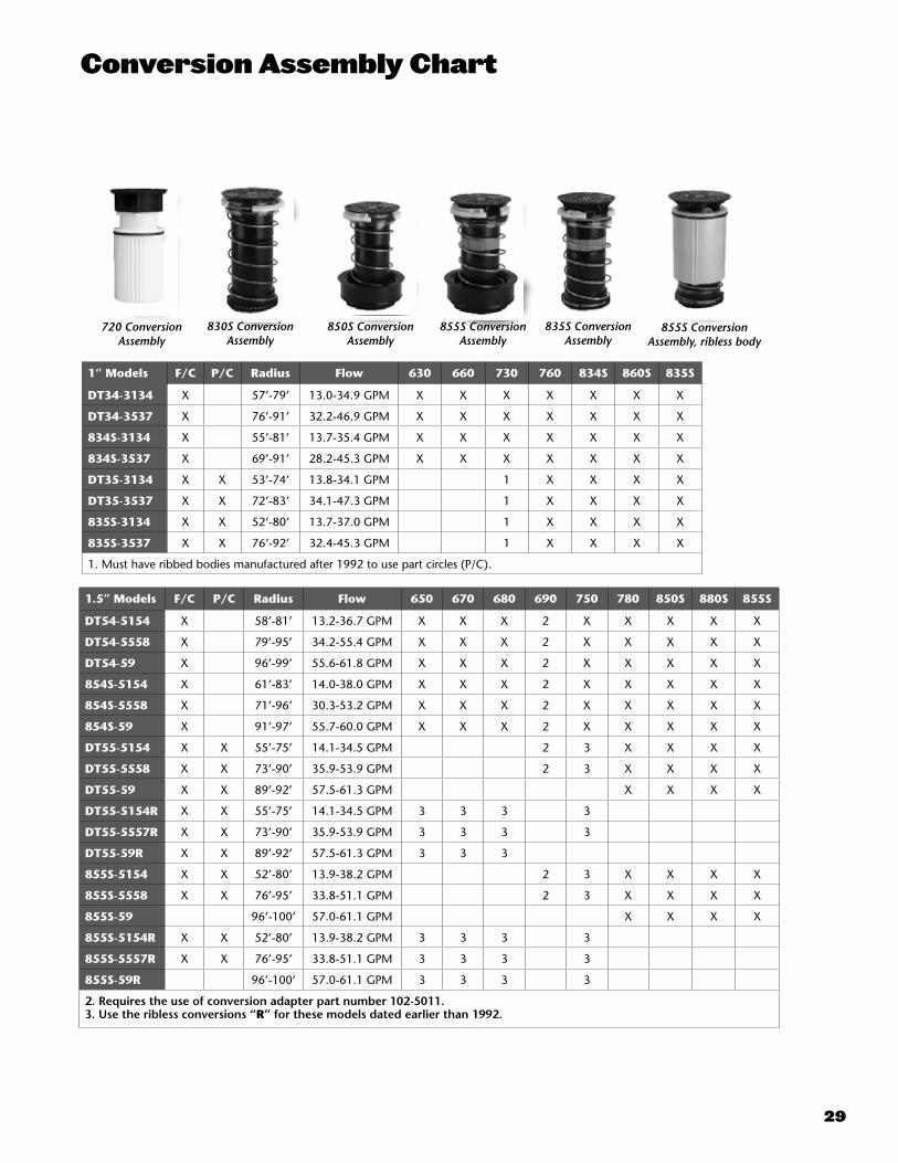
1” Models F/C P/C Radius Flow 630 660 730 760 834S 860S 835S
DT34-3134 X 57’-79’ 13.0-34.9 GPM X X X X X X X
DT34-3537 X 76’-91’ 32.2-46.9 GPM X X X X X X X
834S-3134 X 55’-81’ 13.7-35.4 GPM X X X X X X X
834S-3537 X 69’-91’ 28.2-45.3 GPM X X X X X X X
DT35-3134 X X 53’-74’ 13.8-34.1 GPM 1 X X X X
DT35-3537 X X 72’-83’ 34.1-47.3 GPM 1 X X X X
835S-3134 X X 52’-80’ 13.7-37.0 GPM 1 X X X X
835S-3537 X X 76’-92’ 32.4-45.3 GPM 1 X X X X
1. Must have ribbed bodies manufactured after 1992 to use part circles (P/C).
1.5” Models F/C P/C Radius Flow 650 670 680 690 750 780 850S 880S 855S
DT54-5154 X 58’-81’ 13.2-36.7 GPM X X X 2 X X X X X
DT54-5558 X 79’-95’ 34.2-55.4 GPM X X X 2 X X X X X
DT54-59 X 96’-99’ 55.6-61.8 GPM X X X 2 X X X X X
854S-5154 X 61’-83’ 14.0-38.0 GPM X X X 2 X X X X X
854S-5558 X 71’-96’ 30.3-53.2 GPM X X X 2 X X X X X
854S-59 X 91’-97’ 55.7-60.0 GPM X X X 2 X X X X X
DT55-5154 X X 55’-75’ 14.1-34.5 GPM 2 3 X X X X
DT55-5558 X X 73’-90’ 35.9-53.9 GPM 2 3 X X X X
DT55-59 X X 89’-92’ 57.5-61.3 GPM X X X X
DT55-5154R X X 55’-75’ 14.1-34.5 GPM 3 3 3 3
DT55-5557R X X 73’-90’ 35.9-53.9 GPM 3 3 3 3
DT55-59R X X 89’-92’ 57.5-61.3 GPM 3 3 3
855S-5154 X X 52’-80’ 13.9-38.2 GPM 2 3 X X X X
855S-5558 X X 76’-95’ 33.8-51.1 GPM 2 3 X X X X
855S-59 96’-100’ 57.0-61.1 GPM X X X X
855S-5154R X X 52’-80’ 13.9-38.2 GPM 3 3 3 3
855S-5557R X X 76’-95’ 33.8-51.1 GPM 3 3 3 3
855S-59R 96’-100’ 57.0-61.1 GPM 3 3 3 3
2. Requires the use of conversion adapter part number 102-5011.3. Use the ribless conversions “R” for these models dated earlier than 1992.
720 ConversionAssembly
830S ConversionAssembly
835S ConversionAssembly
850S ConversionAssembly
855S ConversionAssembly
855S Conversion Assembly, ribless body
Conversion Assembly Chart

30
R Series Conversion Assemblies
Specifications
• 60-100 psi – operating pressure range• 150 psi maximum pressure rating
Features
• Trajectory adjustment of the main nozzle for radius reduction and obstacle avoidance - 24 positions from 7-30 degrees in 1 degree increments – 855RB - 2 positions 25 or 15 degrees - DT54RB & DT55RB • Adjustable part/full circle or full circle only models available - Adjustable part circle from 40-330 degrees and true full circle - 855RB & DT55RB - Full circle only - DT54RB• Ratcheting riser allows riser positioning without riser removal• 4 main nozzle combinations included provides a wide range of radius and flow capabilities• Largest and most flexible nozzle offering• Radius reduction screw for radius refinement • All nozzles threaded in from the front with no disassembly required• Back nozzle capable (855RB & DT55RB only) • Two additional front nozzle positions (DT54RB only)• Riser pull up feature simplifies servicing• Nozzle base clutching (855RB & DT55RB only) allows nozzle base movement by hand• Effluent identifier included• Yardage marker capable• 3.25” pop up clears the tall grasses
Features
SPIKEGUARD-RB
• 20,000 volt surge protection; 3 times the surge protection of the leading competitor. Save time and money with fewer replacements and less time digging up failed solenoids• Half the amperage of the leading competitor; Run more heads simultaneously (if control system and available water allow) and provides improved performance in low voltage situations
DCLATCH-RB
• Compatible with Toro’s GDC 2-wire control system this solenoid adapter allows a more economical solution when considering a control system upgrade• Sometimes the cost of a complete system upgrade can be a bit overwhelming. This adapter allows you to manage that cost better by maintaining your existing sprinkler bodies and upgrading just the controls. • Solenoids are 100% compatible with all Toro sprinklers so when it’s time to upgrade the sprinklers your already part way there.
Toro® has designed and manufactured this product to fit within a sprinkler housing made by Rain Bird® Corporation, but Toro’s product is not manufactured by or affiliated with Rain Bird. Rain Bird is a registered trademark of Rain Bird Corporation.
R-Series Solenoid AdaptersThe New Toro solenoid adapters allow you to easily and economically upgrade your Rain Bird® Eagle 700, 900 and 1100 Series sprinklers with the Toro Spike Guard and DC Latching solenoids.
Specifying Information—R Series Solenoid AdaptorsModel Number Description
SPIKEGUARD-RB DCLATCH-RB
Toro solenoid adapter with Spike Guard™ solenoid for Rain Bird Eagle 700, 900 or 1100 Series sprinklers Toro solenoid adapter with DC Latching solenoid for Rain Bird Eagle 700, 900 or 1100 Series sprinklers
Specifying Information—R Series Conversion AssembliesModel Number Description
855RB-5154 855RB-5558 DT55RB-5154 DT55RB-5558 DT54RB-5154 DT54RB-5558
R Series Conversion with 855 riser assembly and low flow nozzle set #51 - #54 R Series Conversion with 855 riser assembly and high flow nozzle set #55 - #58 R Series Conversion with DT55 riser assembly and low flow nozzle set #51 - #54R Series Conversion with DT55 riser assembly and high flow nozzle set #55 - #58R Series Conversion with DT54 riser assembly and low flow nozzle set #51 - #54R Series Conversion with DT54 riser assembly and high flow nozzle set #55 - #58
Adds 1” of pop-up height
855RB DT55RB DT54RB
SPIKEGUARD-RB DCLATCH-RB

31
855RB-5154 Performance Chart 855RB-5558 Performance Chart
Front Nozzle
Positions
Nozzle Set 51 (Yellow)
Nozzle Set 52 (Blue)
Nozzle Set 53 (Brown)
Nozzle Set 54 (Orange)
Nozzle Set 55 (Green)
Nozzle Set 56 (Gray)
Nozzle Set 57 (Black)
Nozzle Set 58 (Red)
102-4587 102-4588 102-4589 102-0728 102-0729 102-0730 102-4261 102-4260Blue Gray Red Gray Orange Gray Orange Gray Blue Gray Blue Gray Orange Gray Blue Gray
102-2925 102-2910 102-2928 102-2910 102-2926 102-2910 102-2926 102-2910 102-2925 102-2910 102-2925 102-2910 102-2926 102-2910 102-2925 102-2910
Back Nozzle
PositionsRed Plug Red Plug Red Plug Red Plug Red Plug Red Plug Red Plug Red Plug
102-4335 102-4335 102-4335 102-4335 102-4335 102-4335 102-4335 102-4335
PSI rad/ft gpm rad/ft gpm rad/ft gpm rad/ft gpm rad/ft gpm rad/ft gpm rad/ft gpm rad/ft gpm60 55 16.1 63 20.3 69 23.4 75 31.3 — — — — — — — —70 56 17.4 66 21.8 70 25.3 76 33.8 — — — — — — — —80 57 18.5 68 23.3 72 27.0 77 36.0 80 39.1 85 41.0 88 45.4 92 49.790 58 19.4 70 24.5 75 28.5 79 38.1 83 41.5 87 43.5 91 48.2 94 52.8100 59 20.5 72 25.9 76 30.0 80 40.2 86 43.7 90 45.7 94 50.6 96 55.3
Stator 102-1939 Yellow 102-1940 WhiteConver. 855RB-5154 855RB-5558
DT55RB-5154 Performance Chart DT55RB-5558 Performance Chart
Front Nozzle
Positions
Nozzle Set 51 (Yellow)
Nozzle Set 52 (Blue)
Nozzle Set 53 (Brown)
Nozzle Set 54 (Orange)
Nozzle Set 55 (Green)
Nozzle Set 56 (Gray)
5Nozzle Set 57 (Black)
Nozzle Set 58 (Red)
102-6906 102-0726 102-6907 102-0728 102-6955 102-6935 102-6936 102-6909Yellow Brown Yellow Yellow Yellow Yellow Yellow Yellow Yellow Green Green Green Green Green Green Green
102-5670 102-5671 102-5670 102-6884 102-5670 102-6884 102-5670 102-6884 102-5670 102-6885 102-6531 102-6885 102-6531 102-6885 102-6531 102-6885
Back Nozzle
PositionsRed Plug Red Plug Red Plug Red Plug Red Plug Red Plug Red Plug Red Plug Red Plug Red Plug Red Plug Red Plug Red Plug Red Plug Red Plug Red Plug
102-4335 102-4335 102-4335 102-4335 102-4335 102-4335 102-4335 102-4335 102-4335 102-4335 102-4335 102-4335 102-4335 102-4335 102-4335 102-4335
PSI rad/ft gpm rad/ft gpm rad/ft gpm rad/ft gpm rad/ft gpm rad/ft gpm rad/ft gpm rad/ft gpm60 56 15.2 57 20.1 66 24.3 68 28.0 — — — — — — — —70 58 16.5 60 21.7 67 26.2 71 30.4 — — — — — — — —80 59 17.5 62 23.1 68 27.8 72 31.7 76 39.7 80 43.1 83 48.2 85 53.090 60 18.4 64 24.5 71 28.8 74 34.5 78 43.1 81 45.1 86 51.2 87 56.0
100 61 19.3 66 25.3 72 30.3 75 36.5 80 45.5 82 49.0 90 54.5 89 59.0Stator 102-1939 Yellow 102-1940 White
Conver. DT55RB-5154 DT55RB-5558
DT54RB-5154 Performance Chart DT54RB-5558 Performance Chart
Front Nozzle
Positions
Nozzle Set 51 (Yellow)
Nozzle Set 52 (Blue)
Nozzle Set 53 (Brown)
Nozzle Set 54 (Orange)
Nozzle Set 55 (Green)
Nozzle Set 56 (Gray)
Nozzle Set 57 (Black)
Nozzle Set 58 (Red)
102-0725 102-7001 102-0727 102-7002 102-6908 102-0730 102-4261 102-4260Red Plug Red Plug Red Plug Red Plug Red Plug Red Plug Red Plug Red Plug Red Plug Red Plug Red Plug Red Plug Red Plug Brown Red Plug Brown102-4335 102-4335 102-4335 102-4335 102-4335 102-4335 102-4335 102-4335 102-4335 102-4335 102-4335 102-4335 102-4335 102-6883 102-4335 102-6883
Back Nozzle
Positions
Yellow Blue Yellow Orange Yellow Red Yellow Beige Yellow Beige Yellow Red Yellow Gray Yellow Gray
102-6937 102-2925 102-6937 102-2926 102-6937 102-2928 102-6937 102-2929 102-6937 102-2929 102-6937 102-2928 102-6937 102-4965 102-6937 102-4965
PSI rad/ft gpm rad/ft gpm rad/ft gpm rad/ft gpm rad/ft gpm rad/ft gpm rad/ft gpm rad/ft gpm60 59 14.6 62 17.4 68 24.3 71 28.2 — — — — — — — —70 60 15.7 63 18.8 70 26.3 75 30.6 — — — — — — — —80 61 16.4 64 20.0 72 27.6 78 32.6 83 39.5 85 42.7 87 45.9 91 50.290 62 17.8 66 21.3 74 29.9 80 34.7 85 41.6 88 44.9 90 48.5 93 52.8100 63 18.1 67 23.6 75 30.4 81 36.7 87 43.7 90 46.8 93 51.2 95 55.4
Stator 102-6929 Blue 102-1940 WhiteConver. DT54RB-5154 DT54RB-5558
■ Not recommended at these pressures. Radius shown in feet.
Toro recommends the use of a 11⁄4" swing joint at flows over 25-GPM (95-LPM). Sprinkler radius data collected in Toro’s zero wind test facility per ASAE standard S398.1.Actual site conditions must be considered when selecting the appropriate nozzle.
All sprinklers are equipped with the selectable pilot valve that allows settings at 50, 65, 80 and 100 psi.

32
810G Series
810G
Features
• Adjustable part and full circle in one—30° - 360°• The flow shut-off features allows you to shut off the water to an individual sprinkler wet or dry• Flanged cap installs below grade• Simple to set adjusting band – arc is factory pre-set to 180°• Smart Arc™ memory returns sprinkler to previously set arc• Below-grade installation• Unique over-molded wiper seal• Cluster, water-lubricated, gear-drive design• Standard rubber cover• Large filter screen• Color-coded nozzle tree with seven nozzles • Factory-installed #12 nozzle
Warranty
• Three years• Five years when installed with Toro swing joints
Dimensions
• Body diameter: 2 3/8” • Body height: 9 ¼” • Weight: .99 lbs.• Pop-up height to nozzle: 4 ¾”
Operating Specifications
• Inlet: 1” female threaded NPT, BSP or ACME• Radius: 30’ – 68’• Flow Rate: 6.6 – 26.3 GPM • Recommended Operating Pressure Range: 40-100 psi • Trajectory: Adjustable 5° to 25°• Check Valve: Reversible check valve prevents low-head drainage (maintains up to 6’ elevation change)
S p e c i f y i n g I n f o r m a t i o n — 8 1 0 G S e r i e s
810G-X2XModel Body Threads Optional
810G X2 X
810G—810G Sprinkler
0—NPT4—ACME5—BSP
E—Effluent
Example: An 810G Series Sprinkler having NPT threads, would be specified as: 810G-02
NozzleSize psi Flow
25° 15° 5°
Radius Precip. Rate* Radius Precip. Rate* Radius Precip. Rate*▲ ■ ▲ ■ ▲ ■
7
Orange
40 6.6 38 0.51 0.44 35 0.60 0.52 30 0.82 0.7150 7.3 40 0.51 0.44 37 0.59 0.51 33 0.75 0.6560 8.1 43 0.49 0.42 40 0.56 0.49 36 0.69 0.6070 8.8 45 0.48 0.42 42 0.55 0.48 39 0.64 0.5680 9.4 46 0.49 0.43 43 0.57 0.49 40 0.65 0.5790 9.9 48 0.48 0.41 45 0.54 0.47 41 0.65 0.57
100 10.4 49 0.48 0.42 46 0.55 0.47 42 0.66 0.57
9
Red
40 7.4 39 0.54 0.47 36 0.63 0.55 32 0.80 0.7050 8.1 41 0.54 0.46 38 0.62 0.54 35 0.73 0.6460 8.7 44 0.50 0.43 41 0.58 0.50 38 0.67 0.5870 9.4 46 0.49 0.43 43 0.57 0.49 40 0.65 0.5780 10 48 0.48 0.42 44 0.57 0.50 41 0.66 0.5790 10.7 49 0.50 0.43 46 0.56 0.49 43 0.64 0.56
100 11.4 51 0.49 0.42 47 0.57 0.50 44 0.65 0.57
12*
Black
40 9.7 40 0.67 0.58 36 0.83 0.72 32 1.05 0.9150 10.5 43 0.63 0.55 40 0.73 0.63 35 0.95 0.8360 11.2 47 0.56 0.49 44 0.64 0.56 38 0.86 0.7570 12 50 0.53 0.46 46 0.63 0.55 42 0.76 0.6580 12.9 52 0.53 0.46 49 0.60 0.52 45 0.71 0.6190 13.8 55 0.51 0.44 51 0.59 0.51 47 0.69 0.60
100 14.7 57 0.50 0.44 53 0.58 0.50 49 0.68 0.59
16
Blue
40 11.9 40 0.83 0.72 36 1.02 0.88 33 1.21 1.0550 13.3 44 0.76 0.66 40 0.92 0.80 36 1.14 0.9960 14.7 48 0.71 0.61 45 0.81 0.70 39 1.07 0.9370 16.1 52 0.66 0.57 47 0.81 0.70 43 0.97 0.8480 17.2 54 0.66 0.57 50 0.76 0.66 46 0.90 0.7890 18.3 57 0.63 0.54 52 0.75 0.65 49 0.85 0.73
100 19.4 59 0.62 0.54 54 0.74 0.64 50 0.86 0.75
20
Green
40 14.2 40 0.99 0.85 36 1.22 1.05 32 1.54 1.3350 15.8 45 0.87 0.75 40 1.10 0.95 35 1.43 1.2460 17.4 49 0.81 0.70 45 0.96 0.83 37 1.41 1.2270 19 54 0.72 0.63 48 0.92 0.79 44 1.09 0.9480 20.2 56 0.72 0.62 51 0.86 0.75 47 1.02 0.8890 21.3 59 0.68 0.59 53 0.84 0.73 50 0.95 0.82
100 22.5 61 0.67 0.58 56 0.80 0.69 51 0.96 0.83
24
Brown
40 14.9 41 0.99 0.85 37 1.21 1.05 32 1.62 1.4050 17.1 46 0.90 0.78 41 1.13 0.98 35 1.55 1.3460 18.3 50 0.81 0.70 46 0.96 0.83 38 1.41 1.2270 19.5 56 0.69 0.60 52 0.80 0.69 45 1.07 0.9380 20.8 58 0.69 0.60 54 0.79 0.69 48 1.00 0.8790 22 60 0.68 0.59 56 0.78 0.68 51 0.94 0.81100 23.2 62 0.67 0.58 57 0.79 0.69 52 0.95 0.83
27
Gray
40 16.6 41 1.10 0.95 38 1.28 1.11 32 1.80 1.5650 18.9 47 0.95 0.82 42 1.19 1.03 38 1.45 1.2660 20.4 51 0.87 0.75 50 0.91 0.79 48 0.98 0.8570 21.9 55 0.80 0.70 54 0.83 0.72 53 0.87 0.7580 23.3 60 0.72 0.62 58 0.77 0.67 55 0.86 0.7490 24.8 64 0.67 0.58 61 0.74 0.64 58 0.82 0.71
100 26.3 68 0.63 0.55 63 0.74 0.64 59 0.84 0.73
*▲ Precipitation rates are for triangular spacing, shown in inches per hour, calculated at 50% of diameter.
■ Precipitation rates are for square spacing, shown in inches per hour, calculated at 50% of diameter.
All performance specifications are based on the stated working pressure available at the base of the sprinkler.Radius shown in feet. Data based on 360°.#12 nozzle comes pre-installed from factory in standard models. Sprinkler radius data collected in Toro’s zero wind test facility per ASAE standard S398.1.Actual site conditions must be considered when selecting the appropriate nozzle.
810G Performance Data
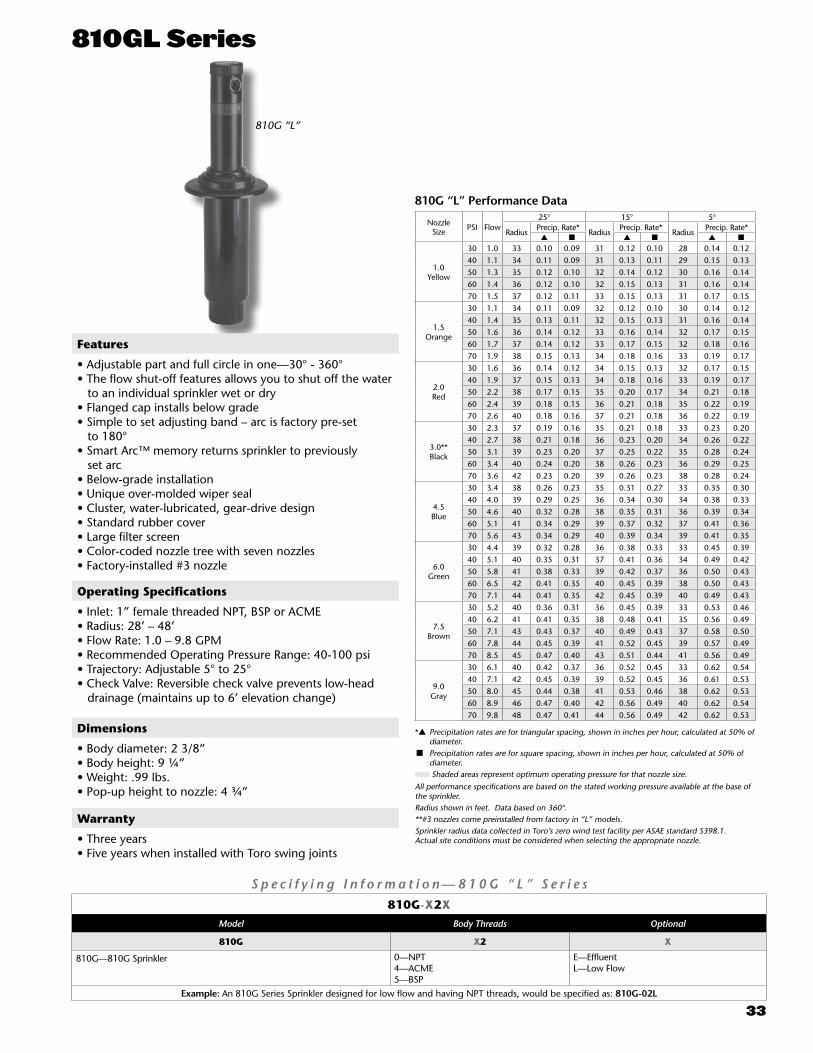
33
810GL Series
810G “L”
Features
• Adjustable part and full circle in one—30° - 360°• The flow shut-off features allows you to shut off the water to an individual sprinkler wet or dry• Flanged cap installs below grade• Simple to set adjusting band – arc is factory pre-set to 180°• Smart Arc™ memory returns sprinkler to previously set arc• Below-grade installation• Unique over-molded wiper seal • Cluster, water-lubricated, gear-drive design• Standard rubber cover• Large filter screen• Color-coded nozzle tree with seven nozzles • Factory-installed #3 nozzle
Warranty
• Three years• Five years when installed with Toro swing joints
Dimensions
• Body diameter: 2 3/8” • Body height: 9 ¼” • Weight: .99 lbs.• Pop-up height to nozzle: 4 ¾”
Operating Specifications
• Inlet: 1” female threaded NPT, BSP or ACME• Radius: 28’ – 48’ • Flow Rate: 1.0 – 9.8 GPM• Recommended Operating Pressure Range: 40-100 psi • Trajectory: Adjustable 5° to 25°• Check Valve: Reversible check valve prevents low-head drainage (maintains up to 6’ elevation change)
S p e c i f y i n g I n f o r m a t i o n — 8 1 0 G “ L ” S e r i e s
810G-X2XModel Body Threads Optional
810G X2 X
810G—810G Sprinkler
0—NPT4—ACME5—BSP
E—EffluentL—Low Flow
Example: An 810G Series Sprinkler designed for low flow and having NPT threads, would be specified as: 810G-02L
Nozzle Size PSI Flow
25° 15° 5°
RadiusPrecip. Rate*
RadiusPrecip. Rate*
RadiusPrecip. Rate*
▲ ■ ▲ ■ ▲ ■
1.0Yellow
30 1.0 33 0.10 0.09 31 0.12 0.10 28 0.14 0.1240 1.1 34 0.11 0.09 31 0.13 0.11 29 0.15 0.1350 1.3 35 0.12 0.10 32 0.14 0.12 30 0.16 0.1460 1.4 36 0.12 0.10 32 0.15 0.13 31 0.16 0.1470 1.5 37 0.12 0.11 33 0.15 0.13 31 0.17 0.15
1.5Orange
30 1.1 34 0.11 0.09 32 0.12 0.10 30 0.14 0.1240 1.4 35 0.13 0.11 32 0.15 0.13 31 0.16 0.1450 1.6 36 0.14 0.12 33 0.16 0.14 32 0.17 0.1560 1.7 37 0.14 0.12 33 0.17 0.15 32 0.18 0.1670 1.9 38 0.15 0.13 34 0.18 0.16 33 0.19 0.17
2.0 Red
30 1.6 36 0.14 0.12 34 0.15 0.13 32 0.17 0.1540 1.9 37 0.15 0.13 34 0.18 0.16 33 0.19 0.1750 2.2 38 0.17 0.15 35 0.20 0.17 34 0.21 0.1860 2.4 39 0.18 0.15 36 0.21 0.18 35 0.22 0.1970 2.6 40 0.18 0.16 37 0.21 0.18 36 0.22 0.19
3.0** Black
30 2.3 37 0.19 0.16 35 0.21 0.18 33 0.23 0.2040 2.7 38 0.21 0.18 36 0.23 0.20 34 0.26 0.2250 3.1 39 0.23 0.20 37 0.25 0.22 35 0.28 0.2460 3.4 40 0.24 0.20 38 0.26 0.23 36 0.29 0.2570 3.6 42 0.23 0.20 39 0.26 0.23 38 0.28 0.24
4.5 Blue
30 3.4 38 0.26 0.23 35 0.31 0.27 33 0.35 0.3040 4.0 39 0.29 0.25 36 0.34 0.30 34 0.38 0.3350 4.6 40 0.32 0.28 38 0.35 0.31 36 0.39 0.3460 5.1 41 0.34 0.29 39 0.37 0.32 37 0.41 0.3670 5.6 43 0.34 0.29 40 0.39 0.34 39 0.41 0.35
6.0 Green
30 4.4 39 0.32 0.28 36 0.38 0.33 33 0.45 0.3940 5.1 40 0.35 0.31 37 0.41 0.36 34 0.49 0.4250 5.8 41 0.38 0.33 39 0.42 0.37 36 0.50 0.4360 6.5 42 0.41 0.35 40 0.45 0.39 38 0.50 0.4370 7.1 44 0.41 0.35 42 0.45 0.39 40 0.49 0.43
7.5 Brown
30 5.2 40 0.36 0.31 36 0.45 0.39 33 0.53 0.4640 6.2 41 0.41 0.35 38 0.48 0.41 35 0.56 0.4950 7.1 43 0.43 0.37 40 0.49 0.43 37 0.58 0.5060 7.8 44 0.45 0.39 41 0.52 0.45 39 0.57 0.4970 8.5 45 0.47 0.40 43 0.51 0.44 41 0.56 0.49
9.0 Gray
30 6.1 40 0.42 0.37 36 0.52 0.45 33 0.62 0.5440 7.1 42 0.45 0.39 39 0.52 0.45 36 0.61 0.5350 8.0 45 0.44 0.38 41 0.53 0.46 38 0.62 0.5360 8.9 46 0.47 0.40 42 0.56 0.49 40 0.62 0.5470 9.8 48 0.47 0.41 44 0.56 0.49 42 0.62 0.53
*▲ Precipitation rates are for triangular spacing, shown in inches per hour, calculated at 50% of diameter.
■ Precipitation rates are for square spacing, shown in inches per hour, calculated at 50% of diameter. Shaded areas represent optimum operating pressure for that nozzle size.
All performance specifications are based on the stated working pressure available at the base of the sprinkler.Radius shown in feet. Data based on 360°. **#3 nozzles come preinstalled from factory in “L” models.Sprinkler radius data collected in Toro’s zero wind test facility per ASAE standard S398.1.Actual site conditions must be considered when selecting the appropriate nozzle.
810G “L” Performance Data l

34
720/720G Series
720 720G
Operating Specifications
• Inlet: - 720: 1” female threaded NPT, BSP or ACME - 720G: ¾” threaded• Radius: - 720: 22’ – 49’ - 720G: 19’ – 49’• Flow Rate: - 720: 3.0 – 9.0 GPM - 720G: 0.85 – 11.62 GPM• Precipitation rates from .10-.45 in./hr.• Optimum Nozzle Performance: 65 psi• Recommended Operating Pressure Range: - 720: Electric; 40-120 psi – Normally Open & Check-O-Matic; 40-90 psi - 720G: 20 – 50 psi• Standard Pressure Regulation for Model 720: 65 psi • Trajectory: Adjustable 5° - 25°• Check-O-Matic: - 720: Maintains up to 37’ elevation - 720G: Maintains up to 10’ elevation• Electric Valve-in-Head Solenoid: 24V ac, 50/60 Hz - Inrush: 60 Hz, 0.12 Amps - Holding: 60 Hz, 0.10 Amps
S p e c i f y i n g I n f o r m a t i o n — 7 2 0 G S e r i e s 72XGE
Arc Optional
72XG E4—Full-circle5—Part-circle
E—Effluent Model
Example: When specifying a full-circle 720G Sprinkler, you would specify: 724G
S p e c i f y i n g I n f o r m a t i o n — 7 2 0 S e r i e s 72X-XX-396E
Body Arc Threads Valve-In-Head Type Nozzle PressureRegulation* Optional
72X X X 39 6 E
4—Full-circle5—Part-circle
0—NPT4—ACME5—BSP
1—N.O. Hydraulic2—Check-O-Matic 6—Electric
Nozzles selection from 3-9
6—65 psi E—Effluent Model
Example: When specifying a full-circle 720 Series Sprinkler with NPT threads, electric valve and pressure regulation at 65 psi, you would specify: 724-06-396
Dimensions
• Body diameter: - 720: 6½” - 720G: 2½”• Body height: - 720: 10” - 720G: 7”
• Weight: - 720: 2.96 lbs. - 720G: .69 lbs• Pop-up height to nozzle: - 720: 2 7/8” - 720G: 2 5/8”
Features
• The MultiMatrx nozzle allows you to select nine different flow settings from the top of the sprinkler wet or dry• The 720 model is a golf valve-in-head body that provides the Spike Guard solenoid, individual head control, pressure regulation at the head, and manual ON-OFF- AUTO control.• The 720G models are a block system style body that requires water supplied from a separate valve and includes a standard rubber cover and check vale and a riser snap ring retention feature that allows riser servicing without digging• Adjustable part/full and true full circle uni-directional model from 40° to 360°• High pop-up height to clear taller grasses• All adjustments made from the top-wet or dry • Balanced precipitation rates• Time-proven planetary gear-drive design• Variable reversing stator• All internal components serviceable from the top of the sprinkler with Servi-Snap™• Durable engineering plastic and stainless steel construction
Warranty
• Three years• Five years when installed with Toro swing joints (720 only)
720G Series MultiMatrx Low-pressure Nozzle Performance Data1.0 1.5 2.0 3.0 4.0 4.5 6.0 8.0 9.0
PSI Radius GPM Radius GPM Radius GPM Radius GPM Radius GPM Radius GPM Radius GPM Radius GPM Radius GPM
25 29 0.85 25 1.05 27 1.44 26 1.85 26 2.73 27 3.23 28 4.00 28 5.0 29 5.5730 30 0.94 27 1.15 29 1.65 28 2.09 30 3.09 30 3.68 31 4.56 31 5.6 33 6.2535 31 1.02 29 1.25 32 1.82 32 2.34 33 3.47 34 4.09 35 5.05 35 6.3 37 6.9640 31 1.08 30 1.33 33 1.96 33 2.54 34 3.72 36 4.42 35 5.51 38 6.8 39 7.5845 31 1.12 31 1.42 31 2.08 34 2.73 35 4.06 39 4.71 39 5.90 42 7.4 42 8.1650 31 1.17 31 1.49 34 2.15 34 2.89 36 4.31 39 4.98 41 6.27 43 7.9 44 8.7555 31 1.21 31 1.55 35 2.29 35 3.04 38 4.52 40 5.23 42 6.61 45 8.26 46 9.2360 32 1.24 30 1.60 35 2.39 35 3.15 38 4.69 40 5.41 43 6.87 45 8.61 47 9.6765 32 1.28 30 1.66 36 2.48 36 3.30 39 4.88 41 5.62 44 7.14 45 8.99 49 10.0970 31 1.31 30 1.70 36 2.57 36 3.42 39 5.05 41 5.84 44 7.43 46 9.29 49 10.4275 30 1.34 30 1.75 37 2.64 37 3.55 39 5.21 42 6.00 44 7.68 47 9.61 49 10.89
= Nozzles not recommended at this pressure. = Low flow setting recommended for 720G models only. = Optimum nozzle performance. All performance specifications are based on the stated working pressure available at the base of the sprinkler.
Radius shown in feet. Data based on 360°.

35
640 Series Performance DataNozzle psi GPM Radius
40
40 6.0 4750 6.7 5060 7.3 5270 8.0 5380 8.6 5490 9.2 55
41
40 9.5 4850 10.2 5360 11.0 5470 11.9 5580 12.7 5690 13.4 57
42
40 12.0 5250 12.9 5560 14.0 5670 14.7 5780 15.8 5890 16.8 58
43
40 13.2 5650 14.5 5960 15.7 5970 17.0 6180 18.3 6390 19.4 64
44
40 16.7 5550 18.6 6060 19.9 6170 21.9 6380 23.4 6590 25.0 67
All performance specifications are based on the stated working pressure available at the base of the sprinkler.
Radius shown in feet. Data based on 360°.Note: For the 640, differing arcs cannot be valved together.
Sprinkler radius data collected in Toro’s zero wind test facility per ASAE standard S398.1.Actual site conditions must be considered when selecting the appropriate nozzle.
EffluentCheck-O-Matic Valve in Head
S p e c i f y i n g I n f o r m a t i o n — 6 4 0 S e r i e s 64X-0X-4X-XXXE
Arc Valve Type Nozzle Special Arc Optional
64X 0X 4X XXX E
0—Special Arc1—90°2—180°3—270°4—360°
1—Normally Open Valve-In-Head2—Check-O-Matic
01234
045° 148° 060° 173° 108° 192° 127° 238°
E—Effluent Model
Example: A 640 Series Sprinkler with a 90° arc, 40 nozzle and a check valve, would be specified as: 641–02–40Most 640 sprinklers are available in component parts only. Consult Res/Com Finished Goods Price List (Form No. 8-1000-IRC) for a complete list of sprinklers available as finished goods.
640 Series
640 Series Sprinklers Apex @ 50 psi
Nozzle27°
Max. Ht. of Spray40 11' 6" 41 13' 10" 42 13' 5"
640 Series Sprinklers Apex @ 60 psi
Nozzle27°
Max. Ht. of Spray43 18' 8"
640 Series Sprinklers Apex @ 75 psi
Nozzle27°
Max. Ht. of Spray44 19' 8"
Features
• High pressure with low flow nozzles creates a misting effect to bring the ambient temperature down and reduce turf stress• Twelve fixed arc drive assemblies• Standard rubber cover • Vandal-resistant cap with locking set screw• Gear-drive design • Basket filter screen • Stainless steel retraction spring
Operating Specifications
• Radius: 47’ – 67’• Flow Rate: 6.0 – 25.0 GPM• Recommended Operating Pressure Range: 40-90 psi (maximum-100 psi)• Trajectory: 27°• Pop-up to nozzle: 2 3/8”• Inlet: 1” female-threaded • Below-grade installation: up to ½” • Check-O-Matic maintains up to 15’ elevation change• Selection of five nozzles and 12 arcs • Adjustment screw allows up to 25% radius reduction
Dimensions
• Body diameter: 2 ½”• Cap diameter: 3 ¼”• Body height: Check-O-Matic – 9”; Valve-In-head – 10 ½”• Exposed surface diameter when buried ½” below grade: 1¾”
Warranty• Five years

36
690
690 Series
690 Series Performance ChartBase
PressureNozzle Set
90Nozzle Set
91Nozzle Set
92
psi Radius GPM Radius GPM Radius GPM
80 87 51.0 96 61.2 100 74.0
100 90 57.1 100 73.5 108 82.2
Radius shown in feet.Sprinkler radius of throw per ASAE standard S398.1.
S p e c i f y i n g I n f o r m a t i o n — 6 9 0
69X-0X-XXXArc Valve-In-Head Type Nozzle Pressure Regulation*
69X 0X XX X
1—90° 2—180° 4—Full-circle 6—Full-circle, 2-speed (60°–120°) 8—Full-circle, 2-speed (180°–180°)
1—Normally Open Hydraulic2—Check-O-Matic6—Electric
909192
8—80 psi1—100 psi
Example: When specifying a 690 Series Sprinkler with a 180° arc, electric valve-in-head, #91 nozzle, and pressure regulation at 80 psi, you would specify: 692-06-918
*Electric models only.
Features
• Used in single row applications the 696 2-speed models operate at a slower speed over the 60 degree non-overlap area and a faster speed over the 120 degree overlapped areas to provide a balanced application rate• Used in double row applications the 698 2-speed models operate at a slower speed over the 180 degree non-overlap area and a faster speed over the 180 degree overlapped areas to provide a balanced application rate• Radius and flow capabilities are perfect for cooling and rinsing artificial playing surfaces such as football fields • Manual control at the sprinkler, On-Off-Auto (electric)• Time-proven, gear-drive design• All internal components serviceable from the top of the sprinkler• Durable engineering plastic and stainless steel construction• Nine arc selections
Dimensions
• Body diameter: 10”• Body height: 16” • Weight: 5.6 lbs.• Pop-up height to nozzle: 3/4”
Operating Specifications
• Inlet: 1 ½” NPT• Radius: 87’ – 108’• Flow Rate: 51.0 – 82.2 GPM• Recommended Operating Pressure Range: 80-100 psi Maximum pressure: 150 psi Minimum pressure: 40 psi• Electric Valve-In-Head Solenoid: 24V ac, 50/60 Hz - Inrush: 60 Hz, 0.30 Amps - Holding: 60 Hz, 0.20 Amps• Check-O-Matic: Maintains 37’ of elevation
Warranty
• Three years• Five years when installed with Toro Swing Joints

37
Toro® Swing Joints
1 ¼” Female ACME x 1” Male ACME Adapter
Allows you to upgrade existing Rain Bird® Eagle 700 1 ¼” ACME sprinklers to any Toro 800S or DT Series Sprinkler. P/N TA36-132.
S p e c i f y i n g I n f o r m a t i o n — To r o S w i n g J o i n tTSJ-XXXXXX-XX-X-XXX*
Description Inlet Size Inlet Type Size Length Number of Elbows Outlet Size Outlet TypeTSJ XX XX XX XX X XX X
TSJ— Toro Swing Joint
10—1”12—1.25”15—1.5”
M—MIPT (male pipe thread)S—4” SpigotA—ACME threadGE—Glue elowGT—Glue TeeST—Saddle Tee
Blank—same as inlet size10—1”12—1.25”15—1.5”
12—12” Lay Length18—18” Lay Length
3—Standard Unibody4—Standard Unibody for Saddle Tees5—Ultra Unibody6—Ultra Unibody for Saddle Tees
10—1” 15—1 1/2”
M—MIPT (Male pipe thread)A—ACME threadQC—Quick Coupler
Example: A Toro 1 1/4” Swing Joint with an 1 1/4” ACME inlet, 12” lay length, 3 elbows (standard uni-body) and 1” ACME outlet fitting would be specified as:TSJ-12A-12-3-10A
Features
• Schedule 80 PVC construction• Double o-ring swivel joints• Low friction loss characteristics• 315 psi pressure rating• 800 psi burst pressure safety rating• 1”, 1¼” and 1½” models • Standard models with 2X90 outlet configuration• Ultra models with 4X90 outlet for maximum alignment flexibility• 3 inlet fittings styles; ACME, male thread and 4” spigot• 2 outlet fitting styles; ACME and male thread• 12” and 18” lay lengths• Saddle Tee models; 2” tee w/ 1”, 1¼” or 1½” outlet• Glue Tee models; 2” tee w/ 1”, 1 ¼” or 1½” outlet• Glue 90° models; 2” 90° w/ 1”, 1¼” or 1½” outlet• Quick coupler models w/ Dura-lock anti-rotation feature• Compatible with all brands of service and saddle tees
Warranty
• Five years• Toro Golf sprinkler warranty extended to 5 years when purchased and installed with a Toro Swing Joint.
Toro Tool Tip:
Use a 1¼” hole saw for the 1” Saddle Tee.
Use a 1½” hole saw for the1¼” and 1½” Saddles.
1", 1 1/4" and 1 1/2"
Standard 2x90 and Ultra 4x90
Glue tees, Saddle tees
Quick Coupler
* Not all combinations are available. Contact your Toro distributor for details.

38
590GF Series
590GF-4
590GF-6
590GF-12
Features
• Sprinkler flushes during pop-up and retraction clearing debris from around the riser• X-Flow® shut-off device stops the flow of water if the nozzle is damaged or removed• The standard check valve prevents low head drainage with up to 10’ of elevation change• Flanged cap installs below grade• Stainless steel retraction spring• Ratcheting riser feature for arc adjustment• Pop-up and retraction flushing clears debris for reliable pop-down• Small 2” diameter cap• All bodies shipped with flush plug in place
Warranty
• Three years
Dimensions
• Body diameter: - 1 3/8” on 4P and 6P - 1 5/8” on 12P • Cap diameter: 2” • Inlet: ½” female-threaded
Operating Specifications
• Radius: 2’ – 26’• Recommended pressure range: 25-50 psi (maximum – 75 psi • Flow rate: 0.05 – 4.71 GPM• 2 GPM flush rate
S p e c i f y i n g I n f o r m a t i o n Model Number Description
590GF-4 4” Pop-Up 590GF-4E 4” Pop-Up, Effluent 590GF-6 6” Pop-Up 590GF-6E 6” Pop-Up, Effluent 590GF-12 12” Pop-Up 590GF-12E 12” Pop-Up, Effluent
Risers and Extenders570-6X• 570 extender• Male-inlet threads install onto any 570 pop-up sprinkler or shrub adapter to provide a 6" extension
• Maximum pressure: 75 psi
570-SR-6 and 570SR-18• 570 stationary riser• 1⁄2" male-threaded inlet for installation on pipe fittings
• Maximum pressure: 75 psi• Height: 6" and 18"
S p e c i f y i n g I n f o r m a t i o n Model Number Description
570SR-6 570SR-6 Riser 570SR-18 570SR-18 Riser 570S Shrub Adaptor 570-6X 570-6X Extender
Including: • Precision™ Series Spray Nozzles • Precision™ Series Rotating Nozzles • MPR Nozzles • TVAN Nozzles
The 590GF Uses ALL Toro® Spray Nozzles

39
S p e c i f y i n g I n f o r m a t i o n — D L 2 0 0 0 ®
Model Number Description
SSDS-LF-500SSDS-HF-1000RGP-212-05
DL2000 500' Subsurface Drip System—Low FlowDL2000 1000' Subsurface Drip System—High FlowDL2000 500’ (Roll, 0.5 GPH), 12” Spacing
DL2000® Subsurface Drip Irrigation System
Drip System Specifications
• Flow range: - Low flow: 0.1 to 8.0 GPM - High flow: 2.0 to 20.0 GPM• DL2000 range: - Low flow: 12’ to 1000’ - High flow: 250’ to 2500’• Pressure compensating emitter: 0.5 GPH • DL2000 Maximum run length: 250’• Application rate (12” x 12” spacing): 0.85” per hour
Features
• Pressure compensating emitters• Each emitter is impregnated with Treflan, a root inhibitor that prevents roots from entering and clogging the emitter opening• The airjection system draws a measured amount of air into the system to deliver oxygen rich water directly to the root zone to promote healthy plant growth• The air relief valve opens at the end of every watering cycle allowing clean air to enter the system and eliminate emitter clogging from siphoning • Applies water directly to the root zone allowing turf to stay dry• Uniformly applies water to areas such as fingers• Minimizes runoff• Eliminates overspray into bunker keeping sand dry• Cycle/soak allows for application on steep slopes• Reduces bunker cave-ins• Saves time, labor and money by eliminating the need for
hand-watering
System Components
• DL2000 subsurface dripline - Low Flow system – 500’ - High Flow system – 1000’• Drip Zone Valve Kit – includes control valve, pressure
regulator, Y-filter and manual ball valve• Air Vent Assembly – pre-assembled and ready to install for
labor savings• Required inlet/outlet fittings• Flush Assembly Fittings (8 GPM) 2 psi sealing flush valve• Installation Fittings: - Includes Toro exclusive Loc-Eze® tees, couplings, elbows and end clamps - 10’ of Blue Stripe® polyethylene tubing - Soil staples for secure tubing placement• Pipe thread tape
Warranty
• 2 Years
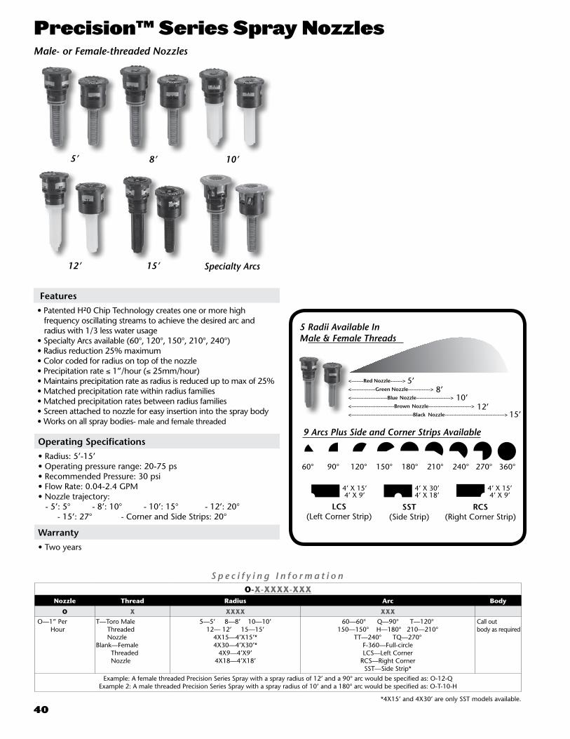
40
Precision™ Series Spray Nozzles
S p e c i f y i n g I n f o r m a t i o nO-X-XXXX-XXX
Nozzle Thread Radius Arc Body
O X XXXX XXX O—1” Per Hour
T—Toro Male Threaded NozzleBlank—Female Threaded Nozzle
5—5’ 8—8’ 10—10’12— 12’ 15—15’
4X15—4’X15’*4X30—4’X30’*
4X9—4’X9’4X18—4’X18’
60—60° Q—90° T—120°150—150° H—180° 210—210°
TT—240° TQ—270°F-360—Full-circle LCS—Left Corner
RCS—Right Corner SST—Side Strip*
Call out body as required
Example: A female threaded Precision Series Spray with a spray radius of 12’ and a 90° arc would be specified as: O-12-QExample 2: A male threaded Precision Series Spray with a spray radius of 10’ and a 180° arc would be specified as: O-T-10-H
*4X15’ and 4X30’ are only SST models available.
60° 90° 120° 150° 180° 210° 240° 270° 360°
5 Radii Available InMale & Female Threads
9 Arcs Plus Side and Corner Strips Available
5’8’
10’12’
15’
LCS (Left Corner Strip)
SST (Side Strip)
RCS (Right Corner Strip)
4’ X 15’4’ X 9’
4’ X 30’4’ X 18’
4’ X 15’4’ X 9’
<-------Red Nozzle------->
<--------------Green Nozzle------------->
<---------------------Blue Nozzle-------------------->
<-------------------------Brown Nozzle------------------------->
<------------------------------------Black Nozzle----------------------------------->
5’ 8’ 10’
12’ 15’ Specialty Arcs
Male- or Female-threaded Nozzles
Features• Patented H²0 Chip Technology creates one or more high frequency oscillating streams to achieve the desired arc and radius with 1/3 less water usage• Specialty Arcs available (60°, 120°, 150°, 210°, 240°)• Radius reduction 25% maximum• Color coded for radius on top of the nozzle• Precipitation rate ≤ 1”/hour (≤ 25mm/hour)• Maintains precipitation rate as radius is reduced up to max of 25%• Matched precipitation rate within radius families• Matched precipitation rates between radius families• Screen attached to nozzle for easy insertion into the spray body• Works on all spray bodies- male and female threaded
Operating Specifications• Radius: 5’-15’ • Operating pressure range: 20-75 ps • Recommended Pressure: 30 psi • Flow Rate: 0.04-2.4 GPM • Nozzle trajectory: - 5’: 5° - 8’: 10° - 10’: 15° - 12’: 20° - 15’: 27° - Corner and Side Strips: 20°
Warranty• Two years

41
Arc PSI GPM Radius Precip.Rate (in./hr.)
Precip. Rate (in./hr.)
5-60°20 0.04 4.7 0.99 1.1530 0.04 5.0 0.99 1.1540 0.04 5.0 0.99 1.1550 0.05 5.3 0.99 1.14
5Q20 0.06 4.6 1.02 1.1830 0.06 5.0 0.99 1.1440 0.07 5.0 1.00 1.1650 0.07 5.0 1.02 1.17
5T20 0.07 4.4 1.01 1.1730 0.09 5.0 1.04 1.2040 0.09 5.2 0.99 1.1550 0.10 5.4 0.98 1.13
5-150°20 0.07 4.0 1.02 1.1830 0.11 5.0 1.03 1.1940 0.12 5.2 1.04 1.2050 0.13 5.4 1.04 1.20
5H20 0.10 4.4 0.99 1.1530 0.13 5.0 1.00 1.1640 0.14 5.1 1.00 1.1550 0.14 5.2 0.99 1.14
5-210°20 0.10 4.4 0.99 1.1530 0.15 5.2 1.07 1.2340 0.16 5.3 1.10 1.2750 0.17 5.5 1.08 1.25
5TT 20 0.14 4.3 1.09 1.2630 0.17 5.0 0.98 1.1340 0.19 5.0 1.07 1.2350 0.19 5.0 1.09 1.25
5TQ 20 0.15 4.3 1.02 1.1730 0.20 5.0 1.00 1.1640 0.21 5.0 1.05 1.2150 0.22 5.0 1.10 1.27
5F 20 0.17 4.0 1.02 1.1830 0.26 5.0 1.00 1.1640 0.26 5.0 1.00 1.1650 0.26 5.0 1.00 1.16
Arc PSI GPM Radius Precip.Rate (in./hr.)
Precip. Rate (in./hr.)
8-60°20 0.10 7.6 1.0 1.230 0.11 8.0 1.0 1.140 0.12 8.1 1.1 1.250 0.13 8.3 1.1 1.3
8Q20 0.14 7.0 1.1 1.330 0.17 8.0 1.0 1.140 0.18 8.2 1.0 1.250 0.18 8.4 1.0 1.1
8T20 0.20 7.6 1.0 1.230 0.22 8.0 1.0 1.140 0.23 8.2 1.0 1.150 0.24 8.3 1.0 1.1
8-150°20 0.25 7.5 1.0 1.230 0.27 8.0 1.0 1.140 0.28 8.1 1.0 1.150 0.29 8.2 1.0 1.2
8H20 0.26 7.0 1.0 1.230 0.33 8.0 1.0 1.140 0.34 8.0 1.0 1.250 0.34 8.0 1.0 1.2
8-210°20 0.33 7.6 1.1 1.330 0.36 8.0 1.1 1.340 0.37 8.1 1.1 1.350 0.38 8.2 1.1 1.3
8TT 20 0.34 7.0 1.0 1.230 0.44 8.0 1.0 1.140 0.46 8.0 1.0 1.250 0.46 8.0 1.0 1.2
8TQ 20 0.41 7.2 1.0 1.130 0.49 8.0 1.1 1.140 0.54 8.0 1.1 1.250 0.55 8.0 1.1 1.2
8F 20 0.55 7.0 1.1 1.230 0.66 8.0 1.0 1.140 0.68 8.0 1.0 1.250 0.71 8.0 1.1 1.2
Arc PSI GPM Radius Precip.Rate (in./hr.)
Precip. Rate (in./hr.)
10-60°20 0.16 9.5 1.0 1.230 0.17 10.0 1.0 1.140 0.18 10.0 1.0 1.250 0.19 10.0 1.1 1.3
10Q20 0.26 9.5 1.0 1.130 0.23 10.0 1.0 1.240 0.28 10.2 1.0 1.250 0.28 10.3 1.0 1.2
10T20 0.31 9.5 1.0 1.130 0.34 10.0 1.0 1.140 0.36 10.0 1.0 1.250 0.37 10.0 1.1 1.2
10-150°
20 0.41 9.8 1.0 1.130 0.43 10.0 1.0 1.140 0.44 10.2 1.0 1.150 0.46 10.4 1.0 1.1
10H20 0.48 9.7 1.0 1.130 0.51 10.0 1.0 1.140 0.55 10.3 1.0 1.250 0.56 10.4 1.0 1.2
10-210°
20 0.56 9.8 1.1 1.330 0.58 10.0 1.1 1.340 0.60 10.4 1.1 1.250 0.62 10.5 1.1 1.3
10TT 20 0.63 9.6 1.0 1.130 0.69 10.0 1.0 1.240 0.73 10.3 1.0 1.150 0.74 10.4 1.0 1.1
10TQ 20 0.71 9.5 1.0 1.130 0.79 10.0 1.0 1.140 0.84 10.3 1.0 1.150 0.86 10.4 1.0 1.1
10F 20 0.95 9.6 1.0 1.130 1.03 10.0 1.0 1.140 1.08 10.3 1.0 1.150 1.12 10.4 1.0 1.2
Arc PSI GPM Radius Precip.Rate (in./hr.)
Precip. Rate (in./hr.)
12-60°20 0.24 11.5 1.0 1.230 0.25 12.0 1.0 1.240 0.26 12.1 1.0 1.250 0.28 12.2 1.1 1.3
12Q20 0.34 12.0 1.0 1.230 0.37 12.1 1.0 1.140 0.39 11.4 1.0 1.250 0.39 12.0 1.0 1.1
12T20 0.46 11.5 1.0 1.230 0.49 12.0 1.0 1.140 0.51 12.2 1.0 1.150 0.52 12.3 1.0 1.1
12-150°
20 0.60 11.6 1.0 1.230 0.62 12.0 1.0 1.240 0.63 12.2 1.0 1.150 0.64 12.3 1.0 1.1
12H20 0.70 11.5 1.0 1.230 0.74 12.0 1.0 1.140 0.79 12.3 1.0 1.250 0.80 12.4 1.0 1.2
12-210°
20 0.76 11.6 1.1 1.330 0.82 12.0 1.1 1.340 0.84 12.3 1.1 1.250 0.85 12.4 1.1 1.2
12TT 20 0.90 11.4 1.0 1.230 0.99 12.0 1.0 1.140 1.04 12.3 1.0 1.150 1.05 12.4 1.0 1.1
12TQ 20 1.05 11.4 1.0 1.230 1.15 12.0 1.0 1.240 1.19 12.2 1.0 1.250 1.22 12.3 1.0 1.2
12F 20 1.35 11.5 1.0 1.130 1.48 12.0 1.0 1.140 1.59 12.4 1.0 1.150 1.60 12.5 1.0 1.1
Arc PSI GPM Radius Precip.Rate (in./hr.)
Precip. Rate (in./hr.)
15-60°20 0.35 14.0 1.0 1.230 0.39 15.0 1.0 1.240 0.40 15.1 1.0 1.250 0.42 15.3 1.0 1.2
15Q20 0.53 14.2 1.0 1.230 0.58 15.0 1.0 1.140 0.60 15.1 1.0 1.250 0.61 15.3 1.0 1.2
15T20 0.72 14.3 1.0 1.230 0.77 15.0 1.0 1.140 0.81 15.3 1.0 1.250 0.82 15.4 1.0 1.2
15-150°
20 0.92 14.7 1.0 1.230 0.96 15.0 1.0 1.240 1.00 15.2 1.0 1.250 1.10 15.3 1.1 1.3
15H20 1.10 14.5 1.0 1.230 1.16 15.0 1.0 1.140 1.25 15.4 1.0 1.250 1.28 15.5 1.0 1.2
15-210°
20 1.15 14.5 1.1 1.230 1.20 15.0 1.0 1.240 1.30 15.5 1.0 1.250 1.40 15.6 1.1 1.3
15TT 20 1.45 14.5 1.0 1.230 1.54 15.0 1.0 1.140 1.58 15.2 1.0 1.150 1.61 15.3 1.0 1.1
15TQ 20 1.72 14.5 1.0 1.230 1.78 15.0 1.0 1.140 1.82 15.0 1.0 1.250 1.90 15.3 1.0 1.2
15F 20 2.20 14.5 1.0 1.230 2.31 15.0 1.0 1.140 2.35 15.2 1.0 1.150 2.40 15.3 1.0 1.1
Arc PSI GPM Radius Precip.Rate (in./hr.)
Precip. Rate (in./hr.)
4X30SST
20 0.62 4x28 1.0 1.130 0.66 4x30 1.1 1.240 0.67 4x30 1.1 1.250 0.68 4x30 1.1 1.3
4X15LCS
20 0.32 4x15 1.0 1.230 0.33 4x15 1.1 1.240 0.34 4x15 1.1 1.350 0.34 4x15 1.1 1.3
4X15RCS
20 0.32 4x15 1.0 1.230 0.33 4x15 1.1 1.240 0.34 4x15 1.1 1.350 0.34 4x15 1.1 1.3
4X18SST
20 0.36 4X18 1.0 1.130 0.37 4X18 1.0 1.140 0.38 4X18 1.0 1.250 0.38 4X18 1.0 1.2
4X9LCS
20 0.18 4X9 1.0 1.130 0.19 4X9 1.0 1.240 0.20 4X9 1.1 1.250 0.20 4X9 1.1 1.1
4X9RCS
20 0.18 4X9 1.0 1.230 0.19 4X9 1.0 1.240 0.20 4X9 1.1 1.250 0.20 4X9 1.1 1.2
Performance Data Precision™ Series Spray Nozzles

42
Operating Specifications• Radius: 14’-26’• Operating pressure range: 20-50 psi (maximum – 75 psi)• Flow Rate: .17-3.68 GPM
WarrantyFive years
Features• Proven planetary gear drive, variable stator and turbine to rotate the nozzle • 15 unique streams with different trajectories• Maximum height of 20° trajectory to fight through wind • Threads onto nearly all sprayheads and shrub adapters (male & female)• Pre-attached screen for easy installation• Radius adjustment of 25% by turning set screw 60°• Color coded to identify adjustable or full circle• Precipitation rate = 0.55”hr on square spacing plans• Maintains precipitation rate as radius is reduced• Adjustable by hand or with included tool• Consistent speed of rotation not affected by pressure
S p e c i f y i n g I n f o r m a t i o n — P r e c i s i o n S e r i e s R o t a t i n g N o z z l ePRN-XX
Model Thread Model
PRN X XPRN—Precision Rotating Nozzle
T—Male ThreadBlank—Female Thread
A—Adjustable arcF— Full-circle
Example: A male threaded Precision Series Rotating nozzle with a 24’ radius and a 180° arc would be specified as: PRN-TAA female threaded Precision Series Rotating nozzle with a 20’ radius and 360° arc would be specified as: PRN-F
Precision™ Series Rotating Nozzles
Male Threaded• PRN-TA: Toro Threaded, 14-26 feet, Adjustable from 45°-270°• PRN-TF: Toro Threaded, 14-26 feet, Full-Circle
Female Threaded
• PRN-A: Threaded, 14-26 feet, Adjustable from 45°-270°• PRN-F: Threaded, 14-26 feet, Full-Circle
Female-threaded
PRN-A
Male-threadedPRN-TA
Female-threaded
PRN-F
Male-threadedPRN-TF
Per formance Data—Precis ion™ Series Rotating Nozzles
Arc PSI GPM Radius Precip.Rate (in./hr.)
Precip. Rate (in./hr.)
45°
20 0.17 14.0 0.67 0.7730 0.19 15.0 0.65 0.7540 0.25 17.0 0.67 0.7750 0.31 18.5 0.70 0.8160 0.35 19.5 0.71 0.8275 0.43 22.0 0.68 0.79
90°
20 0.43 16.0 0.65 0.7530 0.49 17.5 0.62 0.7140 0.62 20.5 0.57 0.6650 0.75 22.5 0.57 0.6660 0.82 23.5 0.57 0.6675 0.92 25.0 0.57 0.65
120°
20 0.48 16.4 0.69 0.7930 0.57 17.5 0.72 0.8340 0.78 20.2 0.55 0.6450 0.97 22.5 0.55 0.6460 1.07 23.5 0.56 0.6575 1.18 25.0 0.55 0.63
180°
20 0.83 15.0 0.71 0.8230 0.94 17.0 0.63 0.7240 1.22 20.5 0.56 0.6550 1.46 22.5 0.56 0.6460 1.61 24.0 0.54 0.6275 1.81 26.0 0.52 0.60
240°
20 1.12 15.0 0.72 0.8330 1.27 17.0 0.63 0.7340 1.56 20.0 0.56 0.6550 1.80 21.5 0.56 0.6560 1.95 22.5 0.56 0.6475 2.20 24.0 0.55 0.64
270°
20 1.08 14.0 0.71 0.8130 1.23 16.0 0.62 0.7140 1.62 19.0 0.57 0.6650 2.00 21.5 0.55 0.6460 2.26 23.0 0.55 0.6375 2.60 25.0 0.53 0.61
360°
20 1.81 15.0 0.77 0.8930 2.00 17.2 0.65 0.7540 2.56 20.9 0.56 0.6550 3.09 22.9 0.57 0.6560 3.34 23.8 0.57 0.6675 3.68 25.6 0.54 0.62
Nozzle data subject to change.

43
Sprinkler Tools995-15 Selector tool • All electric golf sprinklers • Allows user to manually turn the sprinkler “ON”, turn or leave it “OFF” or place it into the “AUTO” position awaiting a command from the controller
995-83 Multi Purpose tool • All Golf sprinklers • Riser pull up for DT and 800S Series.• Riser screen removal on all models.• Upper snap ring remover on all models
995-100 Valve snap ring pliers with screen remover • All Golf sprinklers Lower snap ring removal on all models• Rock screen removal on all DT and 800S Series• Valve removal on all models
995-82 Arc adjustment tool, 3/32” allen wrench • 765,785,865S,885S Arc adjustment of the part circle drives• DT Series Adjustment of the radius reduction screw
Nut Drivers• 995-105 5/16” nut driver DT and 800S Series Trujectory adjustment on 835S/855S models - Inner, intermediate and back nozzle removal on all DT and 800S models• 995-99 5/8” nut driver DT and 800S Series Dual trajectory selection on all DT models - Main nozzle removal on all DT and 800S models• 995-79 7/16” nut driver 834S/854S pre August 2007 - Inner, intermediate and back nozzle removal - 650/760/780/860S/880S Inner, intermediate and back nozzle removal• 995-81 9/16” nut driver 760/780 Series Main nozzle removal• 995-80 1/2” nut driver 760/780/860S/880S Nozzle base jam nut removal• 995-52 1/4” nut driver 660/680 Drive plate nut removal• 995-53 3/8” nut driver 660/680 Cap nut removal
Valve Insertion Tools• 995-xx valve insertion tool, 640 - Aligns and installs valve into the 640 VIH body• 995-76 valve insertion tool, all 1” golf models - Aligns and installs valve into the 1” golf body• 995-101 valve insertion tool, all 1.5” golf models - Aligns and installs valve into the 1.5” golf body• 995-12 valve insertion tool, 690 - Aligns and installs valve into the 690 body• 995-20 valve insertion tool, 690 w/ rubber cover - Aligns and installs valve into the 690 body w/ rubber cover
Valve Removal Tools • 995-08 valve removal tool, 1” All 1” golf models and 640 - Removes valve from the body of all 1” golf sprinklers and the 640• 995-09 valve removal tool, 1.5” All 1.5” models and 690. - Removes valve from the body of all 1.5” goldf sprinklers and the 690
Riser Removal Tools• 995-06 drive assembly extraction tool 630, 650 and 690 models - Threads into the nozzle base and allows removal of the drive from the body• 995-85 drive assembly extraction tool 730,750,760,780,860S,880S - Threads onto the drive output shaft and allows removal of the drive from the body
Riser Hold Up Tools• 995-55 Riser hold up tool, all 700 models - Holds riser up to allow for nozzle servicing• 995-102 Universal hold up tool, all 700, 800S and DT models - Holds riser up to allow for nozzle servicing
89-7350 Adjustment Key, 720/720G• Adjusts flow, arc and trajectory• Removes riser snap ring

44
Valves
Model 220G Series P220G Series P220GS SeriesScrubber
Page Number 45 46 47
Flow Range 5.0-180 GPM 5.0-180 GPM 80.0-150 GPM
Operating Pressure 10-220 Psi Max 10-220 PSI Max 10-220 PSI Max
Conditions Electrically Activated Systems
X X X
Pressure Regulated Systems
X X X
Effluent Water X X X
Sizes
1” (25 mm) X X
1 1/4” (32 mm) X
1 1/2” (40 mm) X X
2” (50 mm) X X X
ConfigurationsAngle X X X
Inline/Globe X X X
Inlet/Outlet Threaded (Female) X X X
Features
Manual Flow Control X X X
Pressure Regulation X X X
Internal Manual Bleed X X X
External Manual Bleed (Flush)
X X X
BodyConstruction
Glass-filled Nylon X X
Brass X
Warranty 5 Years 5 Years 5 Years
Valve Comparison Chart

45
S p e c i f y i n g I n f o r m a t i o n — 2 2 0 G S e r i e s220G-27-0XXXX
Type Body Style Size Optional
220G 27 OX XXX
220G—220G Series Brass Valve 27—NPT, Pressure-regulated (5–100 PSI) 4—1" 5—11
⁄4" 6—11
⁄2" 8—2"
DL—Latching Solenoid for GDC SystemsE—Effluent
Example: A 1" NPT pressure-regulated,220G Series Brass Valve with 60 Hz solenoid, would be specified as: 220G-27-04
220G Series Friction Loss Data
Model TypeGPM Flow
5 10 15 20 30 40 50 60 70 80 100 120 150 170 180 200 250 300 350
1" Electric 2.0 2.5 1.5 2.5 5.5 8.9
11/4" Electric 4.4 4.7 5.1 5.5 5.8 7.2
11/2" Electric 3.9 4.2 4.6 4.9 5.2 5.5 7.2
2" Electric 1.0 2.0 2.0 2.5 3.0 3.5 6.0 7.5 10.0 12.0 14.0Notes: For optimum performance when designing a system, calculate total friction loss to ensure sufficient downstream pressure.
For optimum regulation performance, size regulating valves toward the higher flow ranges.Flow rates are recommended not to exceed 5 psi loss.
Values shown in psi.
Valve Wire Sizing ChartMaximum One-way Distance (in ft.) Between Controller
and Valve Using Spike-Guard™ Solenoid*
Ground WireControl Wire
18 16 14 12 10 8 6
18 2040 2520 2940 3280 3540 3720 3860
16 2520 3260 4000 4660 5220 5620 5920
14 2940 4000 5180 6360 7420 8300 8960
12 3280 4660 6360 8240 10100 11800 13180
10 3540 5220 7420 10100 13180 16060 18770
8 3720 5260 8300 11800 16060 20800 25540
6 3860 5960 8960 13180 18700 25540 33080
* Solenoid Model: 24 V ac Pressure: 150 psi Voltage Drop: 4 V Minimum Operating Voltage: 20 V Amperage (peak) 0.12 A
Dimensions
• 1” – 5 ¼” H x 5” W• 1 ¼” – 6 ½” H x 6” W• 1 ½” - 6 ½” H x 6” W• 2” – 7 ½” H x 7” W
Operating Specifications
• Flow Range: – 1” – 5 to 40 GPM – 1 ¼” – 20 to 100 GPM – 1 ½” – 20 to 130 GPM – 2” – 30 to 180 GPM• Operating Pressure (220 psi maximum pressure rating): – Electric – 10 to 220 psi• Pressure regulating: – Outlet: 5 to 100 psi ± 3 psi• Inlet: 10 to 220 psi• Minimum pressure differential (between inlet and outlet) for pressure regulation: 10 psi• Burst pressure safety rating: 750 psi• Body style: – Globe valve – 1”, 1 ¼”, 1 ½”, 2” female threads• Spike Guard™ Solenoid with 20,000 volt lightning rating: 24 VAC (50/60 Hz) Standard – Inrush: 60 Hz: 0.12 amps – Holding: 60 Hz: 0.1 amps
Warranty
• Five years
Features
• EZ-Reg pressure regulating system can be adjusted from 5-100 PSI.• Self flushing and serviceable stainless steel filter.• Diaphragm stem guide • Ingot brass and stainless steel construction• Pressure regulates in electric and manual modes, serviceable under pressure• Forward-flow design for more precise regulation• Standard, built-in Schrader-type valve for downstream pressure verification• Anti-vandal dust cap on pressure-regulating models• No external tubing • Internal and external manual bleed for system flushing• Manual flow control: adjustable to zero flow• Tough, double-beaded, fabric-reinforced rubber diaphragm• Stainless steel diaphragm support ring for minimum wear• Stainless steel solenoid seat for longer life and positive shutoff• Low-power requirement for longer wire runs
220G Series Brass
220G-27-04
220G-27-06

46
Valve Wire Sizing ChartMaximum One-way Distance (in ft.) Between Controller
and Valve Using Spike-Guard™ Solenoid*
Ground Wire
Control Wire
18 16 14 12 10 8 6
18 2040 2520 2940 3280 3540 3720 3860
16 2520 3260 4000 4660 5220 5620 5920
14 2940 4000 5180 6360 7420 8300 8960
12 3280 4660 6360 8240 10100 11800 13180
10 3540 5220 7420 10100 13180 16060 18770
8 3720 5260 8300 11800 16060 20800 25540
6 3860 5960 8960 13180 18700 25540 33080
* Solenoid Model: 24 V ac Pressure: 150 psi Voltage Drop: 4 V Minimum Operating Voltage: 20 V Amperage (peak) 0.12 A
P-220G Series
P220G-27-06
1½”
P220G-27-08
2”
P220G-27-04
1”
S p e c i f y i n g I n f o r m a t i o n — P 2 2 0 G S e r i e sP220G-27-OXXXX
Type Body Style Size Optional
P220G 27 X XXX
P220G—P220G Series Plastic Valve 27—NPT, Pressure-regulated (5–100 PSI) 4—1" 6—11
⁄2" 8—2"
DL—DC Latching Solenoid for GDC SystemsE—Effluent
Example: A 1” P220G Series plastic electric, pressure-regulating valve with a 60 Hz solenoid, would be specified as: P220G-27-04
P220G Series Friction Loss Data*
Size ConfigurationGPM Flow
5 10 20 30 40 50 60 70 80 90 100 110 120 130 140 150 180 200 225 250 275 300
1" GlobeAngle
4.004.00
4.204.20
3.203.10
4.102.70
7.204.80
11/2" GlobeAngle
1.601.30
2.301.60
3.602.80
5.204.00
7.005.50
9.207.10
11.208.90
13.6010.90
16.4013.80
2" GlobeAngle
2.101.20
2.70 1.60
3.302.00
4.002.40
4.802.80
5.603.30
6.503.90
7.504.40
8.705.20
Note: For optimum performance when designing a system, be sure to calculate total friction loss to ensure sufficient downstream pressure. For optimum regulation performance, size regulating valves toward the higher flow ranges.
Flow rates are recommended not to exceed 5 psi loss.Values shown in psi.
Operating Specifications
• Flow Range: – 1” – 5 to 35 GPM – 1 ½” – 30 to 110 GPM – 2” – 80 to 180 GPM• Operating Pressure (220 psi maximum pressure rating): – Electric – 10 to 220 psi• EZ-Reg® Pressure regulating: – Outlet: 5 to 100 psi ± 3 psi• Inlet: 10 to 220 psi• Minimum pressure differential (between inlet and outlet) for pressure regulation: 10 psi• Burst pressure safety rating: 750 psi• Body styles: – Globe/Angle – 1”, 1 ½”, 2” female threads• Spike Guard™ Solenoid with 20,000 volt lightning rating: 24 VAC (50/60 Hz) Standard – Inrush: 60 Hz: 0.12 amps – Holding: 60 Hz: 0.1 amps
Features
• Double beaded fabric reinforced diaphragm• Glass-filled nylon and stainless steel construction• Internal and External bleed• No external tubing• Standard, built-in Schrader-type valve for downstream pressure verification• Flow control independent of solenoid• Self-aligning bonnet to ensure correct installation• Self-cleaning, stainless steel metering rod• Low-flow capability down to 5 GPM• Low-power requirement for longer wire runs
Dimensions
• 1” – 6 ¾” H x 3 5⁄8” W• 1 ½” – 7 ¼” H x 3 5⁄8” W• 2” – 9 ½” H x 6 1⁄8” W
Warranty
• Five years

47
P-220GS Scrubber Series
Dimensions• 2”: 9 ½” H x 6 1⁄8” W
Operating Specifications
• Flow Range: – 2” 80 to 180 GPM• Operating Pressure – Electric – 20 to 220 psi• Pressure regulating: – Outlet (EZR-30): 5 to 30 psi ± 3 – Outlet (EZR-100): 5 to 100 psi ± 3• Inlet: 10 to 220 psi• Minimum pressure differential (between inlet and outlet) for
pressure regulation: 10 psi • Body styles: – Globe/Angle – 2”• Spike Guard™ Solenoid with 20,000 Volt lightning rating: 24 VAC (50/60 Hz) Standard – Inrush: 60 Hz: 1.2 amps – Holding: 60 Hz: 0.1 amps
S p e c i f y i n g I n f o r m a t i o n — P 2 2 0 SP220GS-27-0-XX
Model Activation Type Size OptionalP220S 27 X X
P220GS—P-220GS Scrubber Series Plastic Valve 7—NPT, Pressure-regulated (5-100 psi) 8—2” DL—Latching Solenoid for GDC SystemsE—Effluent
Example: A 2” (50mm) P220GS Series plastic electric, pressure-regulating valve would be specified as: P220GS-27-08
P-220S Series Friction Loss Data
Size Config.GPM Flow
80 90 100 110 120 130 140 150 180 200 225 250 275 300
2" GlobeAngle
3.872.79
4.293.58
4.415.69
6.505.62
7.786.4
9.307.35
9.948.95
12.159.94
Note: For optimum performance when designing a system, be sure to calculate total friction loss to ensure sufficient downstream pressure. For optimum regulation performance, size regulating valves toward the higher flow ranges.
Flow rates are recommended not to exceed 5 psi loss.
Features
• Active Cleansing Technology (ACT™), the industry’s first active scrubber valve, cleans continuously whereas competitive valves only clean on opening and closing• Fabric-reinforced EPDM Diaphragm and EPDM Seat• Diaphragm assembly may be replaced or retrofitted to previous models• Tough glass-filled nylon and stainless steel construction• Internal and External bleed• Pressure regulates in electric or pressure-regulating models• No external tubing for either pressure-regulating model• Standard, built-in Schrader-type valve for downstream pressure verification• Flow control independent of solenoid• Self-aligning bonnet to ensure correct installation• Self-cleaning, stainless steel metering rod• Low-flow capability down to 5 GPM with EZReg®• 316 nuclear-grade stainless-steel stem for maximum corrosion resistance
Valve Wire Sizing ChartMaximum One-way Distance (in ft.) Between Controller
and Valve Using Spike-Guard™ Solenoid*
Ground Wire
Control Wire
18 16 14 12 10 8 6
18 2040 2520 2940 3280 3540 3720 3860
16 2520 3260 4000 4660 5220 5620 5920
14 2940 4000 5180 6360 7420 8300 8960
12 3280 4660 6360 8240 10100 11800 13180
10 3540 5220 7420 10100 13180 16060 18770
8 3720 5260 8300 11800 16060 20800 25540
6 3860 5960 8960 13180 18700 25540 33080
* Solenoid Model: 24 V ac Pressure: 150 psi Voltage Drop: 4 V Minimum Operating Voltage: 20 V Amperage (peak) 0.12 A

48
470 Quick Coupler Valves
O r d e r i n g I n f o r m a t i o n —Q u i c k C o u p l e r V a l v e A c c e s s o r i e s
Order Number Description
463-01464-01464-02464-03465-01465-02466-01
1⁄2" Female, 3⁄4" Male, Single-lug Coupler Key3⁄4" Female, 1" Male, Single-lug Coupler Key1" Female, Single-lug Coupler Key1" ACME Thread Coupler Key11⁄4" Inlet, 3⁄4" Female, 1" Male, Single-lug Coupler Key1" Female, 11⁄2" Male, Single-lug Coupler Key11⁄4" Female, 11⁄2" Male, Single-lug Coupler Key
477-00477-01477-02
3⁄4" NPT x 3⁄4" MHT Hose Swivel1" NPT x 3⁄4" MHT Hose Swivel1" NPT x 1" MHT Hose Swivel
491-02 Key for Locking Cover
470 Series Friction Loss DataGPM Flow
10 15 20 25 30 35 40 50 60 70 85 100
Model 473 1.5 3.1 5.3 8.5
Model 474 1.1 2.2 3.6 5.7 8.0
Model 475 1.0 1.8 2.7 3.6 6.4 9.8
Model 476 1.0 1.7 2.6 3.6 5.6 8.8Note: For optimum sprinkler performance when designing a system, be sure
to calculate total friction loss to ensure sufficient downstream pressure.Flow rates are recommended not to exceed 5 psi loss. Values listed in psi.
Features
• Full range of flows from 0 to 100 gallons per minute• ¾”, 1” and 1½” one- and two-piece single-lug models including ACME thread key connections to meet a variety of installation requirements• Hose swivel provides 360° movement without hose tangling for ease of use• A variety of sizes meet various applications• Metal and vinyl locking and non-locking covers• Effluent (lavender-colored) locking cover
Warranty
• Two years
Toro ModelNumber Description Inlet Size
NPT ThreadsBodyType
OutletKey Size
CorrespondingKey(s)
Valve Cover Type
CorrespondingSwivel(s)*
477-00 477-01 477-02
473-00 474-00 474-01 474-03 474-04 474-21 474-24474-40474-41 474-44 475-00 475-01 476-00 476-01 476-04
QCV .75, SS CVRQCV 1, SS CVRQCV 1, VYL CVRQCV 1, VYL CVR, W/LKQCV 1, LAV VYL CVRQCV 1, VYL CVR, 2PCQCV 1, LAV VYL CVR, 2PCQCV 1, SS CVR, ACMEQCV 1, VYL CVR, ACMEQCV 1, LAV VYL CVR, W/LK, ACMEQCV 1.25, SS CVRQCV 1.25, VYL CVRQCV 1.5, SS CVRQCV 1.5, VYL CVRQCV 1.5, LAV VYL CVR
3⁄4"1"1"1"1"1"1"1"1"1"1"1"
1 1⁄2"1 1⁄2"1 1⁄2"
1 Piece1 Piece1 Piece1 Piece1 Piece2 Piece2 Piece1 Piece1 Piece1 Piece1 Piece1 Piece1 Piece1 Piece1 Piece
3⁄4"1"1"1"1"1"1"1"1"1"
1¼"1¼"1 1⁄2"1 1⁄2"1 1⁄2"
463-01 464-01 & 464-02 464-01 & 464-02 464-01 & 464-02 464-01 & 464-02 464-01 & 464-02 464-01 & 464-02
464-03 464-03464-03
465-01 & 465-02 465-01 & 465-02
466-01 466-01 466-01
Stainless SteelStainless SteelYellow Vinyl, Spring LoadedYellow Vinyl, Locking, Spring Loaded Lavender Vinyl, Locking, Spring LoadedYellow Vinyl, Spring LoadedLavender Vinyl, Locking, Spring LoadedStainless SteelYellow Vinyl, Spring LoadedLavender Vinyl, Locking, Spring LoadedStainless SteelYellow VinylStainless SteelYellow Vinyl, Spring LoadedLavender Vinyl, Locking, Spring Loaded
AB B B B B B BBB B B B B B
BA A A A A A A AA B B B B B
BAAAAAAA AABBBBB
S p e c i f y i n g I n f o r m a t i o n — Q u i c k C o u p l e r s
474-44
477-00
464-03
473-00

49
CONVERSION INFORMATION
■ All gallons per minute are shown in U.S. ■ To convert to imperial gallons per
minute, multiply by 0.833 ■ To convert to liters per minute, multiply
by 3.78 ■ To convert pounds per square inch (psi)
to atmospheres, divide by 14.7 ■ To convert pounds per square inch (psi)
to kilograms per square centimeter (kg/cm2), divide by 14.22
■ To convert feet to meters, divide by 3.28
WINTERIzING SPECIFICATIONS
In freezing climates, valves should be properly winterized to prevent freeze-related damage.
SPRINKLER SPACING
The Toro Company does not recommend designing for zero (0) mph wind conditions.
■ Square Spacing No wind - 55% of diameter 4 mph wind - 50% of diameter 6,4 kph wind - 50% of diameter 8 mph wind - 45% of diameter 12,8 kph - 45% of diameter
■ Triangular Spacing No wind - 60% of diameter 4 mph wind - 55% of diameter 6,4 kph wind - 55% of diameter 8 mph wind - 50% of diameter 12,8 kph - 50% of diameter
■ Single Row Spacing No wind - 50% of diameter 4 mph wind - 50% of diameter 6,4 kph wind - 50% of diameter 8 mph wind - 45% of diameter 12,8 kph - 45% of diameter
Design in consideration of the worst wind conditions.
PRECIPITATION RATE FORMULAS
■ Square-spaced sprinklers in pattern:
GPM of full-circle x 96.3
(Spacing)2
■ Triangular-spaced sprinklers in pattern:
GPM of full-circle x 96.3
(Spacing)2 (.866)
■ Area and flow:
Total GPM of zone x 96.3
Total irrigated square feet of zone
■ Single row:
GPM of full-circle x 96.3
(Spacing) (Scallop)
Electric • Pressure regulation feature
available to ensure that all heads operate at the same pressure—regardless of elevation changes
• Manual On-Off-Auto control at the sprinkler
• Individual sprinkler control for more precise watering
Normally Open • Individual sprinkler control for
more precise watering• Hydraulic control capability with
sophisticated electronic/electric control systems
• Ideal for all dirty water applications—irrigation water is not used for control
• Lightning resistant
Check-O-Matic • Maintains 37' elevation change• Eliminates low-head drainage• Requires separate remote
control valve
Valve-In-Head Activation Types
Technical Data
VALVE SPECIFICATIONS
CONTROL SySTEMS
Type of System Max. Distance From Controller to Valve
Elevation Restrictions
Pin Type£ (00) Hydraulic* with 3⁄16" Control Tubing
100'
Pin Type£ (00) Hydraulic* with 1⁄4" Control Tubing
200'
Normally Open (01) with 3⁄16" Control Tubing
500' Valve elevation should not exceed 25' ABOVEor 70' BELOW controller elevation.
Normally Closed (08) Hydraulic with 3⁄16" Control Tubing
500' Valve elevation should not exceed 0' ABOVE or 70' BELOW controller elevation.
Normally Open (01) with 1⁄4" Control Tubing
1000' Valve elevation should not exceed 25' ABOVE or 70' BELOW controller elevation.
Normally Closed (08) Hydraulic with 1⁄4" Control Tubing
1000' Valve elevation should not exceed 0' ABOVE or 70' BELOW controller elevation.
Electric (06) Depends on variables• Voltage available• Wire size
NONE
* - All hydraulic connections on Toro valves are 1⁄4" insert type. £ Maximum of one (1) valve per station on
- Control line pressure must be equal to or greater than mainline pressure. pin type systems. - Control line pressure range is 40 to 150 psi.* * Minimum solenoid voltage required for reliable electric VIH operation is 19.5 V ac
Technical Data Book
Form No. 490-1737

50
Standard Wattage Solenoid
Product Solenoids
Assumes 24 VAC, 50/60 Hz Output120 VAC, 60 Hz 240 VAC, 50 Hz
Inrush Holding Inrush HoldingNetwork VP
Satellite 0 — 0.20 — 0.19 1 0.26 0.25 0.30 0.22 2 0.35 0.30 0.34 0.25 3 0.40 0.34 0.36 0.28 4 0.46 0.39 0.39 0.30 5 0.50 0.43 0.42 0.33 6 0.64 0.48 0.44 0.36 7 0.70 0.52 0.46 0.38 8 0.73 0.56 0.50 0.41 9 0.77 0.61 0.53 0.4310 0.80 0.65 0.57 0.4611 0.85 0.69 0.57 0.4812 0.91 0.73 0.57 0.5113 1.00 0.77 0.61 0.5314 1.03 0.81 0.62 0.5515 1.05 0.85 0.63 0.5816 1.14 0.88 0.66 0.60
Network LTCSatellite
0 0.15 0.15 0.08 0.08 1 0.23 0.21 0.12 0.11 2 0.31 0.27 0.17 0.14 3 0.39 0.33 0.22 0.17 4 0.47 0.39 0.26 0.20 5 0.55 0.45 0.31 0.24 6 0.63 0.51 0.36 0.27 7 0.71 0.57 0.40 0.30 8 0.79 0.63 0.45 0.33 9 0.87 0.69 0.50 0.3610 0.95 0.75 0.55 0.4011 1.03 0.81 0.59 0.4312 1.11 0.87 0.64 0.46
E-SeriesOSMACSatellite
0 0.05 0.05 0.03 0.031 0.13 0.11 0.07 0.062 0.21 0.17 0.12 0.093 0.29 0.23 0.17 0.124 0.37 0.29 0.21 0.155 0.45 0.35 0.26 0.196 0.53 0.41 0.31 0.227 0.61 0.47 0.35 0.258 0.69 0.53 0.40 0.289 0.77 0.59 0.45 0.3110 0.85 0.65 0.50 0.3511 0.93 0.71 0.54 0.3812 1.01 0.77 0.59 0.4113 1.09 0.83 0.64 0.4414 1.17 0.89 0.68 0.4715 1.25 0.95 0.73 0.5116 1.33 1.01 0.81 0.54
Spike Guard™ Low Wattage Solenoid
Product Solenoids
Assumes 24 VAC, 50/60 Hz Output120 VAC, 60 Hz 240 VAC, 50 Hz
Inrush Holding Inrush HoldingNetwork VP
Satellite 0 — 0.20 0.21 0.20 1 0.24 0.22 0.22 0.21 2 0.26 0.24 0.23 0.22 3 0.29 0.27 0.24 0.23 4 0.31 0.29 0.25 0.24 5 0.33 0.31 0.26 0.26 6 0.35 0.33 0.28 0.27 7 0.39 0.37 0.29 0.28 8 0.41 0.39 0.30 0.30 9 0.43 0.41 0.32 0.3110 0.46 0.44 0.34 0.3311 0.47 0.46 0.35 0.3512 0.49 0.48 0.36 0.3613 0.52 0.50 0.37 0.3814 0.54 0.52 0.38 0.3915 0.56 0.54 0.40 0.4016 0.58 0.56 0.43 0.4217 0.60 0.58 0.44 0.4318 0.61 0.60 0.46 0.4519 0.63 0.62 0.47 0.4620 0.66 0.64 0.49 0.4821 0.68 0.66 0.50 0.4922 0.70 0.68 0.51 0.5023 0.74 0.70 0.53 0.5224 0.76 0.72 0.54 0.5325 0.79 0.74 0.55 0.5426 0.80 0.75 0.57 0.5627 0.85 0.77 0.58 0.5728 0.90 0.79 0.59 0.5829 0.93 0.81 0.60 0.5930 0.96 0.82 0.61 0.6031 1.01 0.84 0.62 0.6132 1.04 0.86 0.64 0.62
Network LTCSatellite and
Network LTC Plus Satellite
0 0.15 0.15 0.08 0.08 1 0.17 0.17 0.10 0.10 2 0.20 0.19 0.11 0.11 3 0.22 0.21 0.13 0.13 4 0.25 0.23 0.15 0.14 5 0.27 0.25 0.17 0.16 6 0.29 0.27 0.18 0.17 7 0.32 0.29 0.20 0.19 8 0.34 0.31 0.22 0.20 9 0.37 0.33 0.23 0.2210 0.39 0.35 0.25 0.2311 0.41 0.37 0.27 0.2512 0.44 0.39 0.28 0.26
E-OSMACSatellite
0 0.05 0.05 0.03 0.031 0.07 0.07 0.05 0.052 0.10 0.09 0.06 0.063 0.12 0.11 0.08 0.084 0.15 0.13 0.10 0.095 0.17 0.15 0.12 0.116 0.19 0.17 0.13 0.127 0.22 0.19 0.15 0.148 0.24 0.21 0.17 0.159 0.27 0.23 0.18 0.1710 0.29 0.25 0.20 0.1811 0.31 0.27 0.22 0.2012 0.34 0.29 0.23 0.2113 0.36 0.31 0.25 0.2314 0.39 0.33 0.27 0.2415 0.41 0.35 0.29 0.2616 0.44 0.37 0.30 0.27
Wire SizingCurrent Draw (Amperage)

51
We reserve the right to improve our products and make changes in the specifications and designs without notice and without incurring obligation. Products depicted in this brochure are for demonstration purposes only. Actual products offered for sale may vary in design and features.
The Toro Company and its affiliate, Toro Warranty Company, pursuant to an agreement between them, jointly warrants to the owner, each new piece of irrigation equipment (featured in the current catalog at date of installation) against defects in material and workmanship for a period described below, provided they are used for irrigation purposes under manufacturer’s recommended specifications.
During the warranty period, we will repair or replace, at our option, any part found to be defective. Your remedy is limited solely to the replacement or repair of defective parts.
This warranty does not apply (i) to Acts of God (e.g., lightning, flooding, etc.); or (ii) to products not manufactured by Toro when used in conjunction with Toro products; or (iii) where equipment is used, or installation is performed in any manner contrary to Toro’s specifications and instructions, nor where equipment is altered or modified.
Return the defective part to your irrigation contractor or installer, or your local Golf Irrigation Distributor, or contact The Toro Warranty Company, P.O. Box 489, Riverside, California 92502, (800) 664-4740 for the location of your nearest Toro distributor or outside the U.S., call (951) 688-9221.
Neither Toro nor Toro Warranty Company is liable for indirect, incidental or consequential damages in connection with the use of equipment, including but not
The Toro Limited Warranty for Golf Irrigation Equipment
limited to: vegetation loss, the cost of substitute equipment or services required during periods of malfunction or resulting non-use, property damage or personal injury resulting from installer’s actions, whether negligent or otherwise.Some states do not allow the exclusion of incidental or consequential damages, so the above exclusion may not apply to you.
All implied warranties, including those of merchantability and fitness for use, are limited to the duration of this express warranty.
Some states do not allow limitations on how long an implied warranty lasts, so the above limitation may not apply to you.
This warranty gives you specific legal rights and you may have other rights which vary from state to state.
Golf Sprinklers
All Toro golf sprinklers and conversion assemblies are covered by this warranty for 3 years from date the date of installation. Proof of installation date required for any warranty claim.
All Toro golf sprinklers purchased and installed with a Toro swing joint will be covered by a 5-year Warranty*. Proof of simultaneous installation required for any warranty claim.
Swing Joints
Toro swing joints are covered by this warranty for 5 years from the date of installation. Proof of installation date required for any warranty claim.
Valves
220G Series and P-220G Series valves are covered by this warranty for 5 years from date of installation. 470 Series quick coupler valves are covered by this warranty for 2 years from date of installation.
DL2000 Subsurface Drip Irrigation
Toro DL2000 Subsurface Drip Irrigation products are covered by this warranty for 2 years from date of installation.
Control Systems and Turf Guard®
All Toro golf control systems (central controls, field satellite controllers, GDC and Turf Guard), unless covered by a Toro NSN Support Plan, are covered by this warranty for 1 year from date of installation.
* Excludes 720G Series, 590GF Series and sprinkler conversion assemblies.