Embed Size (px)
Citation preview

8/14/2019 GMED unit 2 reading material.doc
http://slidepdf.com/reader/full/gmed-unit-2-reading-materialdoc 1/47
Sand casting, also known as sand molded casting, is a metal casting process
characterized by using sand as the mold material. It is relatively cheap and
sufficiently refractory even for steel foundry use. A suitable bonding agent (usually
clay) is mixed or occurs with the sand. he mixture is moistened with water to
develop strength and plasticity of the clay and to make the aggregate suitable for
molding. he term !sand casting! can also refer to a casting produced via the sand
casting process. "and castings are produced in specialized factories called foundries.
#ver $%& of all metal castings are produced via a sand casting process.
here are six steps in this process'
1.lace a pattern in sand to create a mold.
. Incorporate the pattern and sand in a gating system.
*. +emove the pattern.
. -ill the mold cavity with molten metal.
. Allow the metal to cool.
/. 0reak away the sand mold and remove the casting.

8/14/2019 GMED unit 2 reading material.doc
http://slidepdf.com/reader/full/gmed-unit-2-reading-materialdoc 2/47
Die casting is a metal casting process that is characterized by forcing molten
metal under high pressure into a mold cavity. he mold cavity is created using two
hardened tool steel dies which have been machined into shape and work similarly to
an in1ection mold during the process. 2ost die castings are made from non3
ferrous metals,
specifically zinc, copper , aluminium, magnesium, lead, pewter and tin based alloys.
4epending on the type of metal being cast, a hot3 or cold3chamber machine is used.
he casting e5uipment and the metal dies represent large capital costs and this tends
to limit the process to high volume production. 2anufacture of parts using die casting
is relatively simple, involving only four main steps, which keeps the incremental cost per item low. It is especially suited for a large 5uantity of small to medium sized
castings, which is why die casting produces more castings than any other casting
process. 4ie castings are characterized by a very good surface finish (by casting
standards) and dimensional consistency.
wo variants are pore3free die casting, which is used to eliminate gas porosity defects6
and direct in1ection die casting, which is used with zinc castings to reduce scrap and
increase yield.
8/14/2019 GMED unit 2 reading material.doc
http://slidepdf.com/reader/full/gmed-unit-2-reading-materialdoc 3/47
he main die casting alloys are' zinc, aluminium, magnesium, copper, lead, and tin6
although uncommon, ferrous die casting is possible.78 "pecific dies casting alloys
include' 9A2A: 6zinc aluminium6 aluminium to, e.g. he Aluminum
Association (AA) standards' AA *;%, AA *;, AA *;/, AA *<%6 and A9<=4
magnesium.7/8 he following is a summary of the advantages of each alloy' 7=8
9inc' the easiest alloy to cast6 high ductility6 high impact strength6 easily
plated6 economical for small parts6 promotes long die life.
Aluminium' lightweight6 high dimensional stability for complex shapes and
thin walls6 good corrosion resistance6 good mechanical properties6 high thermal
and electrical conductivity6 retains strength at high temperatures.
2agnesium' the easiest alloy to machine6 excellent strength3to3weight ratio6
lightest alloy commonly die cast.
>opper' high hardness6 high corrosion resistance6 highest mechanical
properties of alloys die cast6 excellent wear resistance6 excellent dimensional
stability6 strength approaching that of steel parts.
?ead and tin' high density6 extremely close dimensional accuracy6 used for
special forms of corrosion resistance. "uch alloys are not used
in foodservice applications for health reasons.
An engine block with aluminium and magnesium die castings.
Advantages and disadvantages
8/14/2019 GMED unit 2 reading material.doc
http://slidepdf.com/reader/full/gmed-unit-2-reading-materialdoc 4/47
Advantages'
@xcellent dimensional accuracy (dependent on casting material, but typically
%.= mm for the first . cm (%.%% inch for the first inch) and %.% mm for each
additional centimeter (%.%% inch for each additional inch).
"mooth cast surfaces (+a =. micrometres or %.%%.=% thou rms).
hinner walls can be cast as compared to sand and permanent mold casting
(approximately %.$ mm or %.%*% in).
Inserts can be cast3in (such as threaded inserts, heating elements, and high
strength bearing surfaces).
+educes or eliminates secondary machining operations.
+apid production rates.
>asting tensile strength as high as = megapascals (/% ksi).
he main disadvantage to die casting is the very high capital cost. 0oth the casting
e5uipment re5uired and the dies and related components are very costly, as compared
to most other casting processes. herefore to make die casting an economic process a
large production volume is needed. #ther disadvantages include' the process is
limited to high3fluidity metals and casting weights must be between *% grams (= oz)and =% kg (% lb). In the standard die casting process the final casting will have a
small amount of porosity. his prevents any heat treating or welding, because the heat
causes the gas in the pores to expand, which causes micro3cracks inside the part and
exfoliation of the surface.

8/14/2019 GMED unit 2 reading material.doc
http://slidepdf.com/reader/full/gmed-unit-2-reading-materialdoc 5/47

8/14/2019 GMED unit 2 reading material.doc
http://slidepdf.com/reader/full/gmed-unit-2-reading-materialdoc 6/47
Investment casting is an industrial process based on and also called lost-wax casting ,
one of the oldest known metal3forming techni5ues.7=8 -rom ,%%% years ago, when
beeswax formed the pattern, to todayBs high3technology waxes, refractory materials
and specialist alloys, the castings allow the production of components with accuracy,
repeatability, versatility and integrity in a variety of metals and high3performance
alloys. ?ost foam casting is a modern form of investment casting that eliminates
certain steps in the process.
he process is generally used for small castings, but has been used to produce
complete aircraft door frames, steel castings of up to *%% kg (//% lbs)
and aluminium castings of up to *% kg (// lbs). It is generally more expensive per unit
than die casting or sand casting, but has lower e5uipment costs. It can produce
complicated shapes that would be difficult or impossible with die casting, yet like that
process, it re5uires little surface finishing and only minor machining.
Applications
Investment casting is used in the aerospace and power generation industries to
produce turbine blades with complex shapes or cooling systems. 0lades produced by
investment casting can include single3crystal ("C), directionally solidified (4"), or
conventional e5uiaxed blades. Investment casting is also widely used by firearms
manufacturers to fabricate firearm receivers, triggers, hammers, and other precision
parts at low cost. #ther industries that use standard investment3cast parts include
military, medical, commercial and automotive.
Inlet-outlet cover of a valve for a nuclear power station produced using investment casting

8/14/2019 GMED unit 2 reading material.doc
http://slidepdf.com/reader/full/gmed-unit-2-reading-materialdoc 7/47

8/14/2019 GMED unit 2 reading material.doc
http://slidepdf.com/reader/full/gmed-unit-2-reading-materialdoc 8/47

8/14/2019 GMED unit 2 reading material.doc
http://slidepdf.com/reader/full/gmed-unit-2-reading-materialdoc 9/47

8/14/2019 GMED unit 2 reading material.doc
http://slidepdf.com/reader/full/gmed-unit-2-reading-materialdoc 10/47

8/14/2019 GMED unit 2 reading material.doc
http://slidepdf.com/reader/full/gmed-unit-2-reading-materialdoc 11/47

8/14/2019 GMED unit 2 reading material.doc
http://slidepdf.com/reader/full/gmed-unit-2-reading-materialdoc 12/47
Forging is a manufacturing process involving the shaping of metal using localized
compressive forces. -orging is often classified according to the temperature at which
it is performed' D!cold,! !warm,! or !hot! forging. -orged parts can range in weight
from less than a kilogram to ;% metric tons.7=878 -orged parts usually re5uire further
processing to achieve a finished part.
Advantages and disadvantages
-orging can produce a piece that is stronger than an e5uivalent cast or machined part.
As the metal is shaped during the forging process, its internal grain deforms to follow
the general shape of the part. As a result, the grain is continuous throughout the part,
giving rise to a piece with improved strength characteristics.
"ome metals may be forged cold6 however iron and steel are almost always hot
forged. Eot forging prevents the work hardening that would result from cold forging,
which would increase the difficulty of performing secondary machining operations on
the piece. Also, while work hardening may be desirable in some circumstances, other
methods of hardening the piece, such as heat treating, are generally more economical
and more controllable. Alloys that are amenable to precipitation hardening, such as
most aluminium alloys and titanium, can be hot forged, followed by hardening.
here are many different kinds of forging processes available6 however they can be
grouped into three main classes'
4rawn out' length increases, cross3section decreases

8/14/2019 GMED unit 2 reading material.doc
http://slidepdf.com/reader/full/gmed-unit-2-reading-materialdoc 13/47
Fpset' length decreases, cross3section increases
"5ueezed in closed compression dies' produces multidirectional flow
>ommon forging processes include' roll forging, swaging, cogging, open3die forging,
impression3die forging, press forging, automatic hot forging and upsetting.7=8
Drop forging
4rop forging is a forging process where a hammer is raised up and then !dropped!
onto the work piece to deform it according to the shape of the die. here are two types
of drop forging' open-die drop forging and closed-die drop forging . As the names
imply, the difference is in the shape of the die, with the former not fully enclosing the
work piece, while the latter does.
A cross-section of a forged connecting rod that has been etched to show the grain flow
Upset forging
Fpset forging increases the diameter of the workpiece by compressing its
length. 0ased on number of pieces produced this is the most widely used forging
process. A few examples of common parts produced using the upset forging processare engine valves, couplings, bolts, screws, and other fasteners.
he following three rules must be followed when designing parts to be upset forged'
he length of unsupported metal that can be upset in one blow without
in1urious buckling should be limited to three times the diameter of the bar.
?engths of stock greater than three times the diameter may be upset
successfully provided that the diameter of the upset is not more than =. times the
diameter of the stock.

8/14/2019 GMED unit 2 reading material.doc
http://slidepdf.com/reader/full/gmed-unit-2-reading-materialdoc 14/47
In an upset re5uiring stock length greater than three times the diameter of the
stock, and where the diameter of the cavity is not more than =. times the diameter
of the stock, the length of unsupported metal beyond the face of the die must not
exceed the diameter of the bar.
Press forging
ress forging works by slowly applying a continuous pressure or force, which differs
from the near3instantaneous impact of drop3hammer forging. he amount of time the
dies are in contact with the workpiece is measured in seconds (as compared to the
milliseconds of drop3hammer forges). he press forging operation can be done either
cold or hot.
he main advantage of press forging, as compared to drop3hammer forging, is its
ability to deform the complete workpiece. 4rop3hammer forging usually only deforms
the surfaces of the workpiece in contact with the hammer and anvil6 the interior of the
workpiece will stay relatively unreformed. Another advantage to the process includes
the knowledge of the new partDs strain rate. Ge specifically know what kind of strain
can be put on the part, because the compression rate of the press forging operation is
controlled. here are a few disadvantages to this process, most stemming from the
workpiece being in contact with the dies for such an extended period of time. he
operation is a time consuming process due to the amount of steps and how long each
of them take. he workpiece will cool faster because the dies are in contact with
workpiece6 the dies facilitate drastically more heat transfer than the surrounding
atmosphere. As the workpiece cools it becomes stronger and less ductile, which may
induce cracking if deformation continues. herefore heated dies are usually used to
reduce heat loss, promote surface flow, and enable the production of finer details and
closer tolerances. he workpiece may also need to be reheated. Ghen done in high
productivity, press forging is more economical than hammer forging. he operation
also creates closer tolerances. In hammer forging a lot of the work is absorbed by the
machinery, when in press forging, the greater percentage of work is used in the work
piece. Another advantage is that the operation can be used to create any size part
because there is no limit to the size of the press forging machine. Hew press forging
techni5ues have been able to create a higher degree of mechanical and orientation

8/14/2019 GMED unit 2 reading material.doc
http://slidepdf.com/reader/full/gmed-unit-2-reading-materialdoc 15/47
integrity. 0y the constraint of oxidation to the outer most layers of the part material,
reduced levels of micro cracking take place in the finished part.
ress forging can be used to perform all types of forging, including open3die and
impression3die forging. Impression3die press forging usually re5uires less draft than
drop forging and has better dimensional accuracy. Also, press forgings can often be
done in one closing of the dies, allowing for easy automation.
8/14/2019 GMED unit 2 reading material.doc
http://slidepdf.com/reader/full/gmed-unit-2-reading-materialdoc 16/47
A rolling-element bearing, also known as a rolling bearing, is a bearing which
carries a load by placing round elements between the two pieces. he relative motion
of the pieces causes the round elements to roll with very little rolling resistance and
with little sliding.
#ne of the earliest and best3known rolling3element bearings are sets of logs laid on
the ground with a large stone block on top. As the stone is pulled, the logs roll along
the ground with little sliding friction. As each log comes out the back, it is moved to
the front where the block then rolls on to it. It is possible to imitate such a bearing by
placing several pens or pencils on a table and placing an item on top of them. "ee
! bearings! for more on the historical development of bearings.
A rolling3element rotary bearing uses a shaft in a much larger hole, and cylinders
called !rollers! tightly fill the space between the shaft and hole. As the shaft turns,
each roller acts as the logs in the above example. Eowever, since the bearing is round,
the rollers never fall out from under the load.
+olling3element bearings have the advantage of a good tradeoffs between cost, size,
weight, carrying capacity, durability, accuracy, friction, and so on. #ther bearing
designs are often better on one specific attribute, but worse in most other attributes,
although fluid bearings can sometimes simultaneously outperform on carrying
capacity, durability, accuracy, friction, rotation rate and sometimes cost. #nly plain
bearings are used as widely as rolling3element bearings.
Types of rolling elements
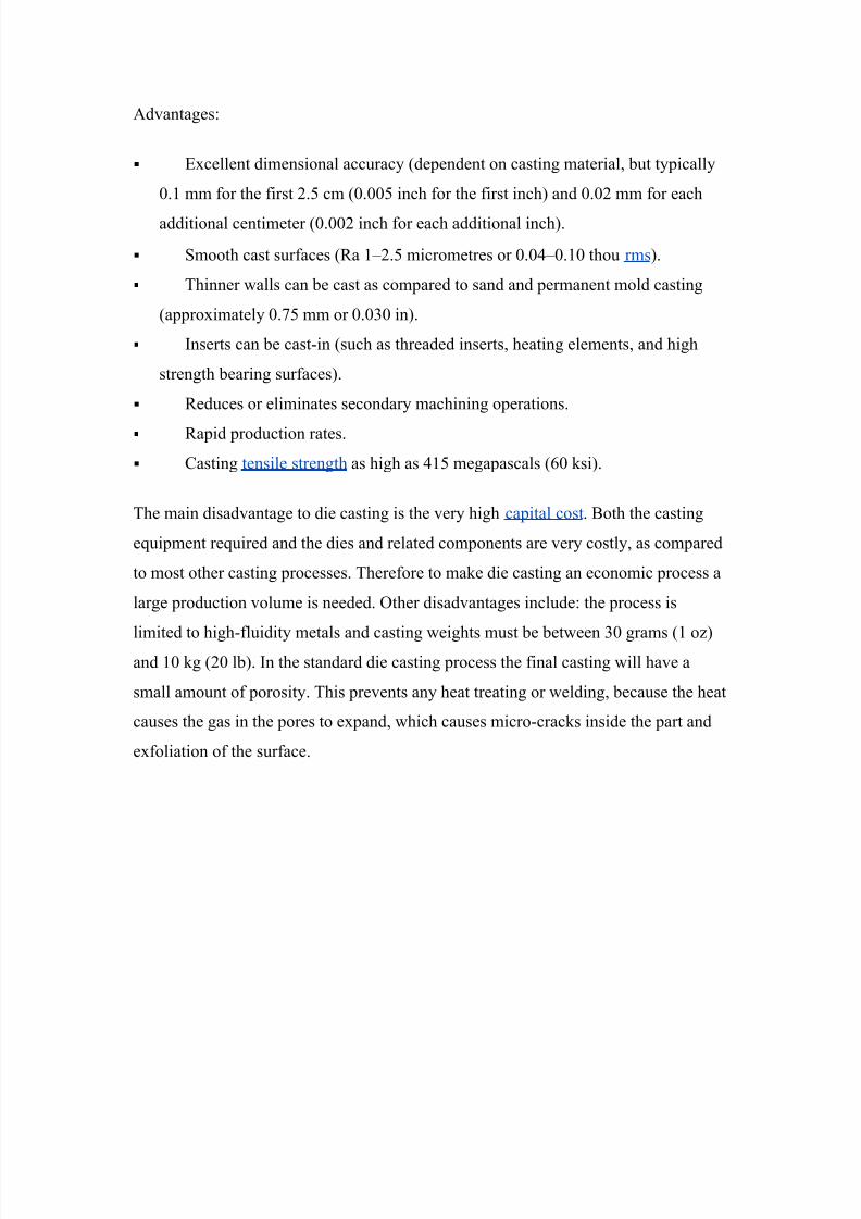
There are five types of rolling-elements that are used in rolling element bearings: balls,
cylindrical rollers, tapered rollers, spherical rollers, and needles.
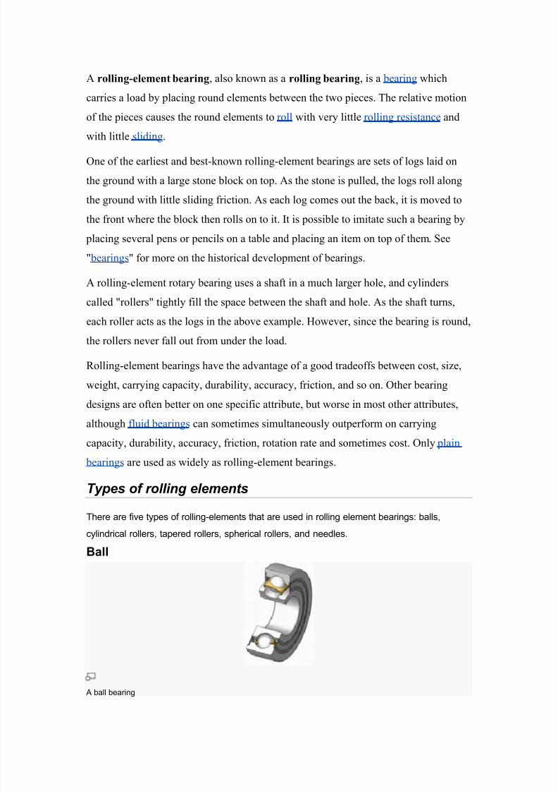
Ball
A ball bearing

8/14/2019 GMED unit 2 reading material.doc
http://slidepdf.com/reader/full/gmed-unit-2-reading-materialdoc 17/47
Ball bearings use balls instead of cylinders. Ball bearings can support
both radial perpendicular to the shaft! and a"ial loads parallel to the shaft!. #or lightly loaded
bearings, balls offer lower friction than rollers. Ball bearings can operate when the bearing
races are misaligned. $recision balls are typically cheaper to produce than shapes such as
rollers% combined with high-volume use, ball bearings are often much cheaper than other
bearings of similar dimensions. Ball bearings may have high point loads, limiting total load
capacity compared to other bearings of similar dimensions.
Cylindrical roller
A roller bearing
&ommon roller bearings use cylinders of slightly greater length than diameter. 'oller bearings
typically have higher load capacity than ball bearings, but a lower capacity and higher friction
under loads perpendicular to the primary supported direction. If the inner and outer races are
misaligned, the bearing capacity often drops (uickly compared to either a ball bearing or a
spherical roller bearing.
'oller bearings are the earliest known type of rolling-element-bearing, dating back to at least
)* B&.
Needle
A needle roller bearing
+eedle roller bearings use very long and thin cylinders. ften the ends of the rollers taper to
points, and these are used to keep the rollers captive, or they may be hemispherical and not
captive but held by the shaft itself or a similar arrangement. ince the rollers are thin, the
outside diameter of the bearing is only slightly larger than the hole in the middle. owever, the
small-diameter rollers must bend sharply where they contact the races, and thus the
bearing fatigues relatively (uickly.

8/14/2019 GMED unit 2 reading material.doc
http://slidepdf.com/reader/full/gmed-unit-2-reading-materialdoc 18/47
Tapered roller
Tapered roller bearings
Tapered roller bearings use conical rollers that run on conical races. /ost roller bearings only
take radial or a"ial loads, but tapered roller bearings support both radial and a"ial loads, and
generally can carry higher loads than ball bearings due to greater contact area. Taper roller
bearings are used, for e"ample, as the wheel bearings of most cars, trucks, buses, and so on.
The downsides to this bearing is that due to manufacturing comple"ities, tapered rollerbearings are usually more e"pensive than ball bearings% and additionally under heavy loads
the tapered roller is like a wedge and bearing loads tend to try to e0ect the roller% the force
from the collar which keeps the roller in the bearing adds to bearing friction compared to ball
bearings.
Spherical roller
pherical roller bearings
pherical roller bearings use rollers that are thicker in the middle and thinner at the ends% the
race is shaped to match. pherical roller bearings can thus ad0ust to support misaligned
loads. owever, spherical rollers are difficult to produce and thus e"pensive, and the bearings
have higher friction than a comparable ball bearing since different parts of the spherical rollers
run at different speeds on the rounded race and thus there are opposing forces along the
bearing1race contact.

8/14/2019 GMED unit 2 reading material.doc
http://slidepdf.com/reader/full/gmed-unit-2-reading-materialdoc 19/47
A ball bearing is a type of rolling3element bearing that uses balls to maintain the
separation between the moving parts of the bearing. he purpose of a ball bearing is
to reduce rotational friction and support radial and axial loads. It achieves this by
using at least two races to contain the balls and transmit the loads through the balls.
Fsually one of the races is held fixed. As one of the bearing races rotates it causes the
balls to rotate as well. 0ecause the balls are rolling they have a much
lower coefficient of friction than if two flat surfaces were rotating on each other.
0all bearings tend to have lower load capacity for their size than other kinds of
rolling3element bearings due to the smaller contact area between the balls and races.
Eowever, they can tolerate some misalignment of the inner and outer races.
>ompared to other rolling3element bearings, the ball bearing is the least expensive,
primarily because of the low cost of producing the balls used in the bearing.
2ing(uist3s and 4#3s self-aligning ball bearing A ) point angular contact ball bearing
Applications
oday the ball bearing is used in numerous everyday applications. 0all bearings are
used for dental and medical instruments. In dental and medical hand pieces, it is
necessary for the pieces to withstand sterilization and corrosion. 0ecause of this
re5uirement, dental and medical hand pieces are made from %> stainless steel,
which allows smooth rotations at fast speeds.
• "kateboarding. he wheels in a skateboard contain two bearings in each of the
four wheels.
• o3oDs, there are 0all bearings in the center of high 5uality o3oDs.
• Agricultural @5uipment. he many moving parts in a piece of farm machinery
depend on several different types of bearings to operate. Fnder the heavy

8/14/2019 GMED unit 2 reading material.doc
http://slidepdf.com/reader/full/gmed-unit-2-reading-materialdoc 20/47
loads and dusty conditions, these bearings need to be lubricated, repaired, or
replaced often.
Conrad
A Conrad bearing is assembled by placing the inner and outer races radially offset, so
the races touch at one point and have a large gap on the radially opposite side. he
bearing is then filled by placing balls in to the large gap, then distributing them
around the bearing assembly. he act of distributing the balls causes the inner and
outer races to become concentric. If the balls were left free, the balls could resume
their offset locations and the bearing could disassemble itself. hus, a cage is inserted
to hold the balls in their distributed positions. he cage supports no bearing load6 it
serves to keep the balls located. >onrad bearings have the advantage that they take
both radial and axial loads, but the disadvantage they cannot be filled to a full
complement and thus have reduced load3carrying capacity compared to a full3
complement bearing. he >onrad bearing is named for its inventor, +obert >onrad,
who got 0ritish patent =,%/ in =<%* and F.". patent ;,$* in =<%/. robably the
most familiar industrial ball bearing is the deep3groove >onrad style. he bearing is
used in most of the mechanical industries.
Slot-fill
In a slot-fill radial bearing, the inner and outer races are notched so that when they are
aligned, balls can be slipped in the slot to fill the bearing. A slot3fill bearing has the
advantage that the entire groove is filled with balls, called a full complement . A slot3
fill bearing has the disadvantages that it handles axial loads poorly, and the notches
weaken the races. Hote that an angular contact bearing can be disassembled axially
and so can easily be filled with a full complement.
Split-race
he outer race may be split axially or radially, or a hole drilled in it for filling. hese
approaches allow a full complement to be used, but also limit the orientation of loads
or the amount of misalignment the bearing can tolerate. hus, these designs find much
less use.
Rows
here are two row designs' single-row bearings and double-row bearings. 2ost ball
bearings are a single3row design, which means there is one row of bearing balls. his
design works with radial and thrust loads.7=8
A double-row design has two rows of bearing balls. heir disadvantage is they need better alignment than single3row bearings.

8/14/2019 GMED unit 2 reading material.doc
http://slidepdf.com/reader/full/gmed-unit-2-reading-materialdoc 21/47
Flanged
0earings with a flange on the outer ring simplify axial location. he housing for such
bearings can consist of a through3hole of uniform diameter, but the entry face of the
housing (which may be either the outer or inner face) must be machined truly normal
to the hole axis. Eowever such flanges are very expensive to manufacture. A more
cost effective arrangement of the bearing outer ring, with similar benefits, is a snap
ring groove at either or both ends of the outside diameter. he snap ring assumes the
function of a flange.
Caged
>ages are typically used to secure the balls in a >onrad3style ball bearing. In other
construction types they may decrease the number of balls depending on the specific
cage shape, and thus reduce the load capacity. Githout cages the tangential position is
stabilized by sliding of two convex surfaces on each other. Gith a cage the tangential
position is stabilized by a sliding of a convex surface in a matched concave surface,
which avoids dents in the balls and has lower friction. >aged roller bearings were
invented by John Earrison in the mid3=;th century as part of his work on
chronographs.78 >aged bearings were used more fre5uently during wartime steel
shortages for bicycle wheel bearings married to replaceable cups.
Ceramic hybrid ball bearings sing ceramic balls
>eramic bearing balls can weigh up to %& less than steel bearing balls, depending onsize and material. his reduces centrifugal loading and skidding, so hybrid ceramic
bearings can operate %& to %& faster than conventional bearings. his means that
the outer race groove exerts less force inward against the ball as the bearing spins.
his reduction in force reduces the friction and rolling resistance. he lighter ball
allows the bearing to spin faster, and uses less energy to maintain its speed.
>eramic hybrid ball bearings use these ceramic balls in place of steel balls. hey are
constructed with steel inner and outer rings, but ceramic balls6 hence
the hybrid designation.Self-aligning
"elf3aligning ball bearings are constructed with the inner ring and ball assembly
contained within an outer ring that has a spherical raceway. his construction allows
the bearing to tolerate a small angular misalignment resulting from deflection or
improper mounting.

8/14/2019 GMED unit 2 reading material.doc
http://slidepdf.com/reader/full/gmed-unit-2-reading-materialdoc 22/47
A plain bearing, also known as a plane bearing or a friction bearing is the simplest
type of bearing, comprising 1ust a bearing surfaceand no rolling elements. herefore
the 1ournal (i.e., the part of the shaft in contact with the bearing) slides over the
bearing surface. he simplest example of a plain bearing is a shaft rotating in a hole.
A simple linear bearing can be a pair of flat surfaces designed to allow motion6 e.g., a
drawer and the slides it rests on or the ways on the bed of a lathe.
lain bearings, in general, are the least expensive type of bearing. hey are also
compact, light weight, and have a high load3carrying capacity.
Lubrication
he types of lubrication system can be categorized into three groups'
• Class I K bearings that re5uire the application of a lubricant from an external
source
• Class II K 0earings that contain a lubricant within the walls of the bearing
• Class III K bearings made of materials that are the lubricant
@xamples of the second type of bearing are #ilites and plastic bearings made
from polyacetal6 examples of the third type are metalized graphite bearings and -@
bearings.
2ost plain bearings have a plain inner surface, however some are grooved. he
grooves help lubrication enter the bearing and cover the whole 1ournal.
"elf3lubricating plain bearings have a lubricant contained within the bearing walls.
here are many forms of self3lubricating bearings. he first, and most common,
are sintered metal bearings, which have porous walls. he porous walls draw oil in
via capillary action and release the oil when pressure or heat are applied. Another
form is a solid one3piece metal bushing with a figure eight groove channel on the I4
that is filled with graphite. A similar bearing replaces the figure eight groove with
holes that are plugged with graphite6 this allows the bearing to be lubricated inside
and out. he last form is a plastic bearing, which has the lubricant molded into the
bearing. he lubricant is released as the bearing is run in.
here are three main types of lubrication' full-film condition, boundary condition,
and dry condition. -ull3film conditions are when the bearingDs load is carried solely by

8/14/2019 GMED unit 2 reading material.doc
http://slidepdf.com/reader/full/gmed-unit-2-reading-materialdoc 23/47
a film of fluid lubricant and there is no contact between the two bearing surfaces. In
mix or boundary conditions, load is carried partly by direct surface contact and partly
by a film forming between the two. In a dry condition, the full load is carried by
surface3to3surface contact.
0earings that are made from bearing grade materials always run in the dry condition.
he other two classes of plain bearings can run in all three conditions6 the condition in
which a bearing runs is dependent on the operating conditions, load, relative surface
speed, clearance within the bearing, 5uality and 5uantity of lubricant, and temperature
(affecting lubricant viscosity). If the plain bearing is not designed to run in the dry or
boundary condition it will wear out and have a high coefficient of friction. 4ry and
boundary conditions may be experienced even in a fluid bearing when operatingoutside of its normal operating conditions6 e.g., at start3up and shutdown.
A schematic of a 0ournal bearing under a hydrodynamic lubrication state showing how the 0ournal centreline
shifts from the bearing centreline

8/14/2019 GMED unit 2 reading material.doc
http://slidepdf.com/reader/full/gmed-unit-2-reading-materialdoc 24/47
A pillow block, also known as a plummer block or bearing housing, is a pedestal used to
provide support for a rotating shaft with the help of compatible bearings 5 various
accessories. ousing material for a pillow block is typically made of cast iron or cast steel.
A drill bshing, also known as a !ig bshing, is a tool used in metalworking 1igs toguide cutting tools, most commonly drill bits. #ther tools that are commonly used in a
drill bushing include counter bores, countersinks, and reamers. hey are designed to
guide, position, and support the cutting tool.
In the F"A, >ustomary sized bushings are standardized via A"2@ 0<.**
and metric bushings are standardized via A"2@ 0<.**.=.7*878 here are over %,%%%
standard configurations of customary sized bushings.
8/14/2019 GMED unit 2 reading material.doc
http://slidepdf.com/reader/full/gmed-unit-2-reading-materialdoc 25/47
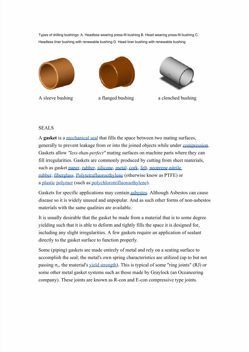
Types of drilling bushings: A. eadless wearing press-fit bushing B. ead wearing press-fit bushing &.
eadless liner bushing with renewable bushing 6. ead liner bushing with renewable bushing
A sleeve bushing a flanged bushing a clenched bushing
"@A?"
A gas"et is a mechanical seal that fills the space between two mating surfaces,
generally to prevent leakage from or into the 1oined ob1ects while under compression.
Laskets allow "less-than-perfect" mating surfaces on machine parts where they can
fill irregularities. Laskets are commonly produced by cutting from sheet materials,
such as gasket paper , rubber , silicone, metal, cork , felt, neoprene,nitrile
rubber , fiberglass, olytetrafluoroethylene (otherwise know as -@) or
a plastic polymer (such as polychlorotrifluoroethylene).
Laskets for specific applications may contain asbestos. Although Asbestos can cause
disease so it is widely unused and unpopular. And as such other forms of non3asbestos
materials with the same 5ualities are available.
It is usually desirable that the gasket be made from a material that is to some degree
yielding such that it is able to deform and tightly fills the space it is designed for,
including any slight irregularities. A few gaskets re5uire an application of sealant
directly to the gasket surface to function properly.
"ome (piping) gaskets are made entirely of metal and rely on a seating surface to
accomplish the seal6 the metalDs own spring characteristics are utilized (up to but not
passing My, the materialDs yield strength). his is typical of some !ring 1oints! (+J) or
some other metal gasket systems such as those made by Lraylock (an #ceaneering
company). hese 1oints are known as +3con and @3con compressive type 1oints.

8/14/2019 GMED unit 2 reading material.doc
http://slidepdf.com/reader/full/gmed-unit-2-reading-materialdoc 26/47
"ome seals and gaskets
=. #3ring
. -iber washer
*. aper gaskets. >ylinder head gasket (for a carBs engine)

8/14/2019 GMED unit 2 reading material.doc
http://slidepdf.com/reader/full/gmed-unit-2-reading-materialdoc 27/47
A garter spring is a coil spring tied end-to-end to provide a clamping force around an ob0ect.
They are often used to maintain the function of radial shaft seals by keeping
the elastomer seals tight against the rotating shaft.
A garter spring inside a rubber seal

8/14/2019 GMED unit 2 reading material.doc
http://slidepdf.com/reader/full/gmed-unit-2-reading-materialdoc 28/47
A circle cotter , also known as a cotter ring or split ring, is a formed wire fastener that is
shaped like a circle, hence the name. The open end of the wire is in the middle of the cotter
so when it is installed the inner tab is first installed in the hole. Because of this feature it is
often used in applications where a sharp edge cannot be tolerated, such
as fabric applications.

8/14/2019 GMED unit 2 reading material.doc
http://slidepdf.com/reader/full/gmed-unit-2-reading-materialdoc 29/47
A labyrinth seal is a type of mechanical seal that provides a tortuous path to help
prevent leakage. An example of such a seal is sometimes found within
an axleDs bearing to help prevent the leakage of the oil lubricating the bearing.
A labyrinth seal may be composed of many grooves that press tightly inside another
axle, or inside a hole, so that the fluid has to pass through a long and difficult path to
escape. "ometimes screw threads exist on the outer and inner portion. hese interlock,
to produce the long characteristic path which slows leakage. -or labyrinth seals on a
rotating shaft, a very small clearance must exist between the tips of the labyrinth
threads and the running surface.
?abyrinth seals on rotating shafts provide non3contact sealing action by controlling
the passage of fluid through a variety of chambers by centrifugal motion, as well as by
the formation of controlled fluid vortices. At higher speeds, centrifugal motion forces
the li5uid towards the outside and therefore away from any passages. "imilarly, if the
labyrinth chambers are correctly designed, any li5uid that has escaped the main
chamber, becomes entrapped in a labyrinth chamber, where it is forced into a vortex3
like motion. his acts to prevent its escape, and also acts to repel any other fluid.
0ecause these labyrinth seals are non3contact, they do not wear out.

8/14/2019 GMED unit 2 reading material.doc
http://slidepdf.com/reader/full/gmed-unit-2-reading-materialdoc 30/47
2any gas turbine engines, having high rotational speeds, use labyrinth seals due to
their lack of friction and long life.
?abyrinth seals are also found on pistons, which use them to store oil and seal against
high pressure during compression and power strokes, as well as on other non3rotatingshafts. In these applications, it is the long and difficult path and the formation of
controlled fluid vortices plus some limited contact3sealing action that creates the seal.
A simple labyrinth seal

8/14/2019 GMED unit 2 reading material.doc
http://slidepdf.com/reader/full/gmed-unit-2-reading-materialdoc 31/47
Copling
A coupling is a device used to connect two shafts together at their ends for the purpose of
transmitting power. &ouplings do not normally allow disconnection of shafts during operation,
however there are tor(ue limiting couplings which can slip or disconnect when some tor(ue
limit is e"ceeded.
The primary purpose of couplings is to 0oin two pieces of rotating e(uipment while permitting
some degree of misalignment or end movement or both. By careful selection, installation and
maintenance of couplings, substantial savings can be made in reduced maintenance costs
and downtime.
Uses
"haft couplings are used in machinery for several purposes, the most common of
which are the following.
• o provide for the connection of shafts of units that are manufactured
separately such as a motor and generator and to provide for disconnection for
repairs or alternations.

8/14/2019 GMED unit 2 reading material.doc
http://slidepdf.com/reader/full/gmed-unit-2-reading-materialdoc 32/47
• o provide for misalignment of the shafts or to introduce mechanical
flexibility.
• o reduce the transmission of shock loads from one shaft to another.
• o introduce protection against overloads.
• o alter the vibration characteristics of rotating units.
An #ldham copler is a method to transfer tor5ue between two parallel but
not collinear shafts. It has three discs, one coupled to the input, one coupled to the
output, and a middle disc that is 1oined to the first two by tongue and groove.
he tongue and groove on one side is perpendicular to the tongue and groove on the
other. #ften springs are used to reduce backlash of the mechanism. he coupler is
much more compact than, for example, two universal 1oints. he coupler is named
for John #ldham who invented it in Ireland, in =;%, to solve a paddle placement
problem in a steamship design.
he middle disc rotates around its center at the same speed as the input and output
shafts. Its center traces a circular orbit, twice per rotation, around the midpoint
between input and output shafts.
ldham coupler, assembled ldham coupler, disassembled
Rigid copling
A rigid coupling is a unit of hardware used to 1oin two shafts within a motor or
mechanical system. It may be used to connect two separate systems, such as a motor
and a generator, or to repair a connection within a single system. A rigid coupling
may also be added between shafts to reduce shock and wear at the point where the
shafts meet.

8/14/2019 GMED unit 2 reading material.doc
http://slidepdf.com/reader/full/gmed-unit-2-reading-materialdoc 33/47
Ghen 1oining shafts within a machine, mechanics can choose between flexible and
rigid couplings. Ghile flexible units offer some movement and give between the
shafts, rigid couplings are the most effective choice for precise alignment and secure
hold. 0y precisely aligning the two shafts and holding them firmly in place, rigid
couplings help to maximize performance and increase the expected life of the
machine. hese rigid couplings are available in two basic designs to fit the needs of
different applications. "leeve3style couplings are the most affordable and easiest to
use. hey consist of a single tube of material with an inner diameter thatDs e5ual in
size to the shafts. he sleeve slips over the shafts so they meet in the middle of the
coupling. A series of set screws can be tightened so they touch the top of each shaft
and hold them in place without passing all the way through the coupling.
>lamped or compression rigid couplings come in two parts and fit together around the
shafts to form a sleeve. hey offer more flexibility than sleeved models, and can be
used on shafts that are fixed in place. hey generally are large enough so that screws
can pass all the way through the coupling and into the second half to ensure a secure
hold. -langed rigid couplings are designed for heavy loads or industrial e5uipment.
hey consist of short sleeves surrounded by a perpendicular flange. #ne coupling is
placed on each shaft so the two flanges line up face to face. A series of screws or bolts
can then be installed in the flanges to hold them together. 0ecause of their size and
durability, flanged units can be used to bring shafts into alignment before they are
1oined together. +igid couplings are used when precise shaft alignment is re5uired6
shaft misalignment will affect the couplingDs performance as well as its life.
A niversal !oint, niversal copling, U !oint, Cardan !oint, $ardy-Spicer !oint,
or $oo"e%s !oint is a 1oint or coupling in a rigid rod that allows the rod to DbendD in
any direction, and is commonly used in shafts that transmit rotary motion. It consists
of a pair of hinges located close together, oriented at <%N to each other, connected by a
cross shaft.
4rive train for a car >O 1oint for the wheels of a car

8/14/2019 GMED unit 2 reading material.doc
http://slidepdf.com/reader/full/gmed-unit-2-reading-materialdoc 34/47
Cltches
A cltch is a mechanical device which provides for the transmission of power (and
therefore usually motion) from one component (the driving member) to another (the
driven member). he opposite component of the clutch is the brake.
>lutches are used whenever the ability to limit the transmission of power or motion
needs to be controlled either in amount or over time (e.g. electric screwdrivers limit
how much tor5ue is transmitted through use of a clutch6 clutches control whether
automobiles transmit engine power to the wheels).
In the simplest application clutches are employed in devices which have two rotating
shafts. In these devices one shaft is typically attached to a motor or other power unit
(the driving member) while the other shaft (the driven member) provides output
power for work to be done. In a drillfor instance, one shaft is driven by a motor and
the other drives a drill chuck. he clutch connects the two shafts so that they may be
locked together and spin at the same speed (engaged), locked together but spinning at
different speeds (slipping), or unlocked and spinning at different speeds (disengaged).
Clutch for a drive shaft: The clutch disccenter! spins with the flywheel left!. To disengage, the lever is pulled
black arrow!, causing a white pressure plate right! to disengage the green clutch disc from turning the drive
shaft, which turns within the thrust-bearing ring of the lever. +ever will all 7 rings connect, with no gaps.
<iple plate cltch
his type of clutch has several driving members interleaved or !stacked! with several
driven members. It is used in race cars including -=, Indy>ar , Gorld +ally and even
most club racing,motorcycles, automatic transmissions and in some diesel
locomotives with mechanical transmissions. It is also used in some electronically
controlled all3wheel drive systems.

8/14/2019 GMED unit 2 reading material.doc
http://slidepdf.com/reader/full/gmed-unit-2-reading-materialdoc 35/47
Centrifgal
A centrifugal clutch is used in some vehicles (e.g. 2opeds) and also in other
applications where the speed of the engine defines the state of the clutch, for example,in a chainsaw. his clutch system employs centrifugal force to automatically engage
the clutch when the engine rpm rises above a threshold and to automatically
disengage the clutch when the engine rpm falls low enough. he system involves a
clutch shoe or shoes attached to the driven shaft, rotating inside a clutch bell attached
to the output shaft. he shoe(s) are held inwards by springs until centrifugal force
overcomes the spring tension and the shoe(s) make contact with the bell, driving the
output. In the case of a chainsaw this allows the chain to remain stationary whilst the
engine is idling6 once the throttle is pressed and the engine speed rises, the centrifugal
clutch engages and the cutting chain moves. "ee "axomat and Oariomatic
'et vs( dry
A !wet clutch! is immersed in a cooling lubricating fluid which also keeps the
surfaces clean and gives smoother performance and longer life. Get clutches,
however, tend to lose some energy to the li5uid. "ince the surfaces of a wet clutch can
be slippery (as with a motorcycle clutch bathed in engine oil), stacking multiple clutch
disks can compensate for the lower coefficient of friction and so eliminate slippageunder power when fully engaged.
he Eele3"haw clutch was a wet clutch that relied entirely on viscous effects, rather
than on friction. A !dry clutch!, as the name implies, is not bathed in fluid and should
be, literally, dry.
)elt Drives
A belt is a loop of flexible material used to link two or more
rotating shafts mechanically. 0elts may be used as a source of motion, to transmit
power efficiently, or to track relative movement. 0elts are looped over pulleys. In a
two pulley system, the belt can either drive the pulleys in the same direction, or the
belt may be crossed, so that the direction of the shafts is opposite. As a source of
motion, a conveyor belt is one application where the belt is adapted to continually
carry a load between two points. 0elts are the cheapest utility for power transmission
between shafts that may not be axially aligned. ower transmission is achieved byspecially designed belts and pulleys. he demands on a belt drive transmission system

8/14/2019 GMED unit 2 reading material.doc
http://slidepdf.com/reader/full/gmed-unit-2-reading-materialdoc 36/47
are large and this has led to many variations on the theme. hey run smoothly and
with little noise, and cushion motor and bearings against load changes, albeit with less
strength than gears or chains. Eowever, improvements in belt engineering allow use
of belts in systems that only formerly allowed chains or gears.
=. Oee belts (also known as O3belt or wedge rope) solved the slippage and
alignment problem. It is now the basic belt for power transmission. hey
provide the best combination of traction, speed of movement, load of the
bearings, and long service life. he O3belt was developed in =<=$ by John
Lates of the Lates +ubber >ompany. hey are generally endless, and their
general cross3section shape is trapezoidal. he !O! shape of the belt tracks in a
mating groove in the pulley (or sheave), with the result that the belt cannot slipoff. he belt also tends to wedge into the groove as the load increases K the
greater the load, the greater the wedging action K
improving tor5ue transmission and making the O3belt an effective solution,
needing less width and tension than flat belts. O3belts trump flat belts with
their small center distances and high reduction ratios.
. -lat belts were used early in line shafting to transmit power in factories. hey
were also used in countless farming, mining, and logging applications, such
as bucksaws, sawmills, threshers, silo blowers, conveyors for filling corn
cribs or haylofts, balers, water pumps (for wells, mines, or swampy farm
fields), and electrical generators. he flat belt is a simple system of power
transmission that was well suited for its day. It delivered high power for high
speeds (%% hp for =%,%%% ftPmin), in cases of wide belts and large pulleys.
hese drives are bulky, re5uiring high tension leading to high loads, so vee
belts have mainly replaced the flat3belts except when high speed is neededover power.

8/14/2019 GMED unit 2 reading material.doc
http://slidepdf.com/reader/full/gmed-unit-2-reading-materialdoc 37/47
*. iming belts, (also known as toothed, notch, cog, or synchronos belts) are
a positive transfer belt and can track relative movement. hese belts have teeth
that fit into a matching toothed pulley. Ghen correctly tensioned, they have no
slippage, run at constant speed, and are often used to transfer direct motion forindexing or timing purposes (hence their name). hey are often used in lieu of
chains or gears, so there is less noise and a lubrication bath is not
necessary. >amshafts of automobiles, miniature timing systems, and stepper
motors often utilize these belts. iming belts need the least tension of all belts,
and are among the most efficient. hey can bear up to %% hp (=% kG) at
speeds of =/,%%% ftPmin. iming belts with a helical offset tooth design are
available. he helical offset tooth design forms a chevron pattern and causes
the teeth to engage progressively. he chevron pattern design is self3aligning.
he chevron pattern design does not make the noise that some timing belts
make at idiosyncratic speeds, and is more efficient at transferring power (up to
<;&). 4isadvantages include a relatively high purchase cost, the need for
specially fabricated toothed pulleys, less protection from overloading and
1amming, and the lack of clutch action.
. Chain drive is a way of transmitting mechanical power from one place to
another. It is often used to convey power to the wheels of a vehicle,
particularly bicycles and motorcycles. It is also used in a wide variety of

8/14/2019 GMED unit 2 reading material.doc
http://slidepdf.com/reader/full/gmed-unit-2-reading-materialdoc 38/47
machines besides vehicles. 2ost often, the power is conveyed by a roller
chain, known as the drive chain or transmission chain, passing over
a sprocket gear, with the teeth of the gear meshing with the holes in the links
of the chain. he gear is turned, and this pulls the chain putting mechanical
force into the system. Another type of drive chain is the 2orse chain, invented
by the 2orse >hain >ompany of Ithaca, Hew ork , F"A. his has inverted
teeth. "ometimes the power is output by simply rotating the chain, which can
be used to lift or drag ob1ects. In other situations, a second gear is placed and
the power is recovered by attaching shafts or hubs to this gear. hough drive
chains are often simple oval loops, they can also go around corners by placing
more than two gears along the chain6 gears that do not put power into the
system or transmit it out are generally known as idler3wheels. 0y varying the
diameter of the input and output gears with respect to each other, the gear
ratio can be altered, so that, for example, the pedals of a bicycle can spin all
the way around more than once for every rotation of the gear that drives the
wheels.
Use in vehicles
)icycles
>hain drive was the main feature which differentiated the safety bicycle introduced in
=;;, with its two e5ual3sized wheels, from the direct3drive penny3farthing or !high
wheeler! type of bicycle. he popularity of the chain3driven safety bicycle brought
about the demise of the penny3farthing, and is still a basic feature of bicycle design
today.Atomobiles
*ransmitting power to the wheels
>hain final drive, =<= illustration

8/14/2019 GMED unit 2 reading material.doc
http://slidepdf.com/reader/full/gmed-unit-2-reading-materialdoc 39/47
Chain drive was a popular power transmission system from the earliest days of
the automobile. It gained prominence as an alternative to the Système Panhard with
its rigid Hotchiss driveshaft and universal 1oints.
A chain3drive system uses one or more roller chains to transmit power froma differential to the rear axle. his system allowed for a great deal of vertical axle
movement (for example, over bumps), and was simpler to design and build than a
rigid driveshaft in a workable suspension. Also, it had less unsprung weight at the rear
wheels than the Eotchkiss drive, which would have had the weight of the driveshaft to
carry as well, which in turn meant that the tires would last longer.
Internal combustion engines often use chain drive to power the timing chain used to
drive overhead camshaft valve trains. his is an area in which chain drives fre5uently
compete directly with belt drive systems, and an excellent example of some of thedifferences and similarities between the two approaches. -or this application, chains
last longer, but are often harder to replace. 0eing heavier, the chain robs more power,
but is also less likely to fail. he camshaft of a four stroke engine must rotate at half
crankshaft speed, so some form of reduction gearing is needed and a direct drive from
the crankshaft isnDt possible. Alternatives to chain drives include gear trains, bevel
gear and shaft drives, or toothed flexible belt drives.
*ransfer cases
D"ilent chainD drives inside a =<= gearbox
oday, inverted tooth drive chains are commonly used in passenger car and light
truck transfer cases. ransfer case
&otorcycles
>hain drive versus belt drive or use of a driveshaft is a fundamental design decision in
motorcycle design6 nearly all motorcycles use one of these three designs.
"ee 2otorcycle construction for more details.

8/14/2019 GMED unit 2 reading material.doc
http://slidepdf.com/reader/full/gmed-unit-2-reading-materialdoc 40/47
)ra"es
A drm ba"e is a brake in which the friction is caused by a set of shoes or pads that
press against a rotating drum3shaped part called a brake drum.
he term !drum brake! usually means a brake in which shoes press on the inner
surface of the drum. Ghen shoes press on the outside of the drum, it is usually called
a clasp brake. Ghere the drum is pinched between two shoes, similar to a
conventional disk brake, it is sometimes called a !pinch drum brake!, although such
brakes are relatively rare. A related type of brake uses a flexible belt or !band!
wrapping around the outside of a drum, called a band brake.
Doble shoe bra"e system

8/14/2019 GMED unit 2 reading material.doc
http://slidepdf.com/reader/full/gmed-unit-2-reading-materialdoc 41/47
+ears ,+eneral nomenclatre
PRAC*IC. S/.*C$I0+ *$. +.AR
A)#1. P2.AS......
Helical gears offer a refinement over spur gears. he leading edges of the teeth are
not parallel to the axis of rotation, but are set at an angle. "ince the gear is curved, this
angling causes the tooth shape to be a segment of a helix. Eelical gears can be meshed
in a parallel or crossed orientations. he former refers to when the shafts are parallel
to each other6 this is the most common orientation. In the latter, the shafts are non3
parallel, and in this configuration are sometimes known as !skew gears!.

8/14/2019 GMED unit 2 reading material.doc
http://slidepdf.com/reader/full/gmed-unit-2-reading-materialdoc 42/47
he angled teeth engage more gradually than do spur gear teeth causing them to run
more smoothly and 5uietly. Gith parallel helical gears, each pair of teeth first make
contact at a single point at one side of the gear wheel6 a moving curve of contact then
grows gradually across the tooth face to a maximum then recedes until the teeth break
contact at a single point on the opposite side. In spur gears teeth suddenly meet at a
line contact across their entire width causing stress and noise. "pur gears make a
characteristic whine at high speeds and can not take as much tor5ue as helical gears.
Ghereas spur gears are used for low speed applications and those situations where
noise control is not a problem, the use of helical gears is indicated when the
application involves high speeds, large power transmission, or where noise
abatement is important. he speed is considered to be high when the pitch line
velocity exceeds mPs.78
A disadvantage of helical gears is a resultant thrust along the axis of the gear, which
needs to be accommodated by appropriate thrust bearings, and a greater degree
of sliding friction between the meshing teeth, often addressed with additives in the
lubricant.
Spur gears or straight-cut gears are the simplest type of gear. They consist of a cylinder
or disk with the teeth pro0ecting radially, and although they are not straight-sided in form,
the edge of each tooth is straight and aligned parallel to the a"is of rotation. These gears
can be meshed together correctly only if they are fitted to parallel shafts.
8/14/2019 GMED unit 2 reading material.doc
http://slidepdf.com/reader/full/gmed-unit-2-reading-materialdoc 43/47
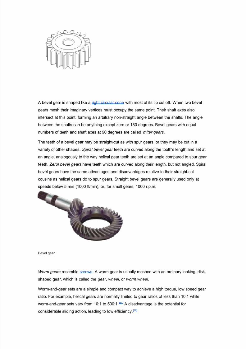
A bevel gear is shaped like a right circular cone with most of its tip cut off. 2hen two bevel
gears mesh their imaginary vertices must occupy the same point. Their shaft a"es also
intersect at this point, forming an arbitrary non-straight angle between the shafts. The angle
between the shafts can be anything e"cept 8ero or 9* degrees. Bevel gears with e(ual
numbers of teeth and shaft a"es at ;* degrees are called miter gears.
The teeth of a bevel gear may be straight-cut as with spur gears, or they may be cut in a
variety of other shapes. Spiral bevel gear teeth are curved along the tooth3s length and set at
an angle, analogously to the way helical gear teeth are set at an angle compared to spur gear
teeth. Zerol bevel gears have teeth which are curved along their length, but not angled. piral
bevel gears have the same advantages and disadvantages relative to their straight-cut
cousins as helical gears do to spur gears. traight bevel gears are generally used only at
speeds below < m1s 9*** ft1min!, or, for small gears, 9*** r.p.m.
Bevel gear
Worm gears resemble screws. A worm gear is usually meshed with an ordinary looking, disk-
shaped gear, which is called the gear , wheel , or worm wheel .
2orm-and-gear sets are a simple and compact way to achieve a high tor(ue, low speed gear
ratio. #or e"ample, helical gears are normally limited to gear ratios of less than 9*:9 while
worm-and-gear sets vary from 9*:9 to <**:9.
=99>
A disadvantage is the potential forconsiderable sliding action, leading to low efficiency.=9?>

8/14/2019 GMED unit 2 reading material.doc
http://slidepdf.com/reader/full/gmed-unit-2-reading-materialdoc 44/47
2orm gears can be considered a species of helical gear, but its heli" angle is usually
somewhat large close to ;* degrees! and its body is usually fairly long in the a"ial direction%
and it is these attributes which give it its screw like (ualities. The distinction between a worm
and a helical gear is made when at least one tooth persists for a full rotation around the heli".
If this occurs, it is a 3worm3% if not, it is a 3helical gear3. A worm may have as few as one tooth.
If that tooth persists for several turns around the heli", the worm will appear, superficially, to
have more than one tooth, but what one in fact sees is the same tooth reappearing at
intervals along the length of the worm. The usual screw nomenclature applies: a one-toothed
worm is called single thread or single start % a worm with more than one tooth is called multiple
thread or multiple start . The heli" angle of a worm is not usually specified. Instead, the lead
angle, which is e(ual to ;* degrees minus the heli" angle, is given.
In a worm-and-gear set, the worm can always drive the gear. owever, if the gear attempts to
drive the worm, it may or may not succeed. $articularly if the lead angle is small, the gear3s
teeth may simply lock against the worm3s teeth, because the force component circumferential
to the worm is not sufficient to overcome friction. 2orm-and-gear sets that do lock are
called self locking, which can be used to advantage, as for instance when it is desired to set
the position of a mechanism by turning the worm and then have the mechanism hold that
position. An e"ample is the machine head found on some types of stringed instruments.
2orm gear

8/14/2019 GMED unit 2 reading material.doc
http://slidepdf.com/reader/full/gmed-unit-2-reading-materialdoc 45/47
&achining #perations
A milling machine also see synonyms below! is a machine tool used
to machine solid materials. /illing machines are often classed in two basic forms, hori8ontal
and vertical, which refers to the orientation of the main spindle. Both types range in si8e from
small, bench-mounted devices to room-si8ed machines. @nlike a drill press, which holds the
workpiece stationary as the drill moves a"ially to penetrate the material, milling machines also
move the workpiece radially against the rotating milling cutter , which cuts on its sides as well
as its tip. 2orkpiece and cutter movement are precisely controlled to less than *.**9 in
*.*?< mm!, usually by means of precision ground slides and lead screws or analogous
technology. /illing machines may be manually operated, mechanically automated, or digitally
automated via computer numerical control &+&!.
/illing machines can perform a vast number of operations, from simple e.g., slot and keyway
cutting, planing, drilling! to comple" e.g., contouring, die sinking!. &utting fluid is often
pumped to the cutting site to cool and lubricate the cut and to wash away the resulting swarf .
1ertical milling machine. =' milling cutter ' spindle *' top slide or over arm '
column ' table /' 3axis slide $' knee ;' base

8/14/2019 GMED unit 2 reading material.doc
http://slidepdf.com/reader/full/gmed-unit-2-reading-materialdoc 46/47
A shaper is a type of machine tool that uses linear relative motion between the workpiece
and a single-point cutting tool to machine a linear tool path. Its cut is analogous to that of
a lathe, e"cept that it is archetypally! linear instead of helical. Adding a"es of motion can
yield helical tool paths, as also done in helical planing.! A shaper is analogous to a planer , but
smaller, and with the cutter riding a ram that moves above a stationary workpiece, rather thanthe entire workpiece moving beneath the cutter. The ram is moved back and forth typically by
a crank inside the column% hydraulically actuated shapers also e"ist.
A lathe is a machine tool which rotates the workpiece on its a"is to perform various
operations such as cutting, sanding, knurling, drilling, or deformation with tools that are
applied to the workpiece to create an ob0ect which has symmetry about an a"is of rotation.
athes are used in woodturning, metalworking, metal spinning, and glass working. athes can
be used to shape pottery, the best-known design being the potter3s wheel. /ost suitably
e(uipped metalworking lathes can also be used to produce most solids of revolution, plane
surfaces and screw threads or helices. rnamental lathes can produce three-dimensional
solids of incredible comple"ity. The material can be held in place by either one or two centers,
at least one of which can be moved hori8ontally to accommodate varying material lengths.
ther work holding methods include clamping the work about the a"is of rotation using a
chuck or collet, or to a faceplate, using clamps or dogs.
"amples of ob0ects that can be produced on a lathe include candlestick holders, cue
sticks, table legs, bowls, baseball bats, musical instruments especially woodwind
instruments!, crankshafts and camshafts.
A metalworking lathe from =<== showing component parts.
a Q bed, b Q carriage (with cross3slide and tool post), c Q headstock, d Q back gear

8/14/2019 GMED unit 2 reading material.doc
http://slidepdf.com/reader/full/gmed-unit-2-reading-materialdoc 47/47
(other gear train nearby below drives lead screw), e Q cone pulley for belt drive from
an external power source, f Q faceplate mounted on spindle, g Q tailstock. h Q lead
screw.