Embed Size (px)
Citation preview

Printed in USA 11/09 P/N 60998 rev. E
GM-FA-10J Gate Monitoring Safety Module24V ac/dc operation, 1- or 2-Channel Input
Features
• Monitorsoneortwosafetyswitchesforacontactfailureorwiringfault
• Twooutputswitchingchannelsforconnectiontocontrol-reliablepowerinterruptcircuits
• Autoresetormonitoredmanualreset
• DesigncomplieswithstandardsUL991,ISO14119,andISO13849-1(EN954-1) (SafetyCategory2,3or4)
• Foruseinfunctionalstopcategory0applicationsperNFPA79 andIEC60204-1
• 6ampsafetyoutputcontacts
• Plug-interminalblocks
• Ifterminalblocksareswapped,Moduleremainsfunctionalwithnolossofsafetyfunction
Emergency Stop Device 29YL
Overview
TheGM-FA-10JGateMonitorSafetyModule(the“SafetyModule”)isusedtoverifytheproperoperationofcodedmagneticsafetyswitchesandpositive-openingsafetyswitchesbymonitoringanormallyopen(N.O.)andanormallyclosed(N.C.)contactfromeachswitch.Itcanalsobeusedtomonitorandverifythecorrectstateoftworedundantcurrent-sourcingPNPsignals.(OnePNPsourcemustbeNormallyOFFandtheotherNormallyConductingforeachinputchannel.)Inatypicalapplication,twosafetyswitches(individuallymounted)indicatetheopenorclosedstatusofagate,moveableguard,orbarrier(allcalled“guards”throughoutthisdocument).
TwofunctionsoftheSafetyModuleare:
1.TomonitorthecontactsandwiringofsafetyswitchesforcertainfailuresandtopreventthemachinefromrestartingiftheswitchortheModulefails,and
2.Toprovidearesetroutineafterclosingtheguardandreturningtheinputstotheir“closed”condition.Thisresetfunctionmayberequiredbymachinesafetystandards.
TheSafetyModulemonitorseachswitchforcomplementaryswitching;eachchannelmusthaveoneopen(OFF)inputandoneclosed(conducting)inputatalltimes.Theseinputsmustalwaysbeinoppositestatesandmustswitchstatewithin1secondofeachother.Channel1hasa“guardclosed”conditionwhenS11/S13isclosedandS11/S12isopen.Similarly,Channel2hasa“guardclosed”conditionwhenS21/S23isclosedandS21/S22isopen(seeFigures2and3).TheSafetyModulealsowilldetectandproperlyrespondtoashortcircuitbetweenthechannelsandashortcircuittoothersourcesofpower.TheSafetyModulewillopenthesafetyoutputswithin35millisecondsoftheswitchingofeitherchannelwhentheguardopens.
Whentheguardcloses,debouncelogicintheSafetyModule’sinputsincreasesthereliabilityandrepeatabilityofsuccessfullyresettingtheSafetyModuleandreducesthenecessityofre-cyclingtheguard.Thisfeaturecanresultinincreasedefficiencyofthemachine,eveniftheguardismisalignedorvibrationispresent.
Original Instructions
Gate Monitoring Safety Module – Model GM-FA-10J
2 P/N 60998 rev. E
Banner Engineering Corp. •Minneapolis,U.S.A.www.bannerengineering.com•Tel:763.544.3164
Banner Engineering Corp. •Minneapolis,U.S.A.www.bannerengineering.com•Tel:763.544.3164
Important ... read this page before proceeding!
The user is responsible for satisfying all local, state, and national laws,rules,codes,andregulationsrelatingtotheuseofthisproductanditsapplication.Pleasedirectanyquestionsregardingtheuseorinstallationofthisproducttothefactoryapplicationsdepartmentatthetelephonenumbersoraddressshownonbackcover.
The user is responsibleformakingsurethatallmachineoperators,maintenancepersonnel,electricians,andsupervisorsarethoroughlyfamiliarwithandunderstandallinstructionsregardingtheinstallation,maintenance,anduseofthisproduct,andwiththemachineryitcontrols.TheuserandanypersonnelinvolvedwiththeinstallationanduseofthisproductmustbethoroughlyfamiliarwithallapplicableANSI/NFPAstandards,someofwhicharelistedbelow.BannerEngineeringCorp.makesnoclaimregardingaspecificrecommendationofanyorganization,theaccuracyoreffectivenessofanyinformationprovided,ortheappropriatenessoftheprovidedinformationforaspecificapplication.
Certificate of Adequacy
ThisSafetyModuledatasheet(p/n60998)satisfiestherequirementsofMachineryDirective2006/42/EC,Section1.7.4—instructions.
Applicable U. S. StandardsANSIB11 StandardsforMachineTools
Availablefrom: SafetyDirector AMT–TheAssociationforManufacturingTechnology 7901WestparkDrive McLean,VA22102-4269 Tel.:703-827-2900
ANSINFPA79 ElectricalStandardforIndustrialMachinery
Availablefrom: NationalFireProtectionAssociation 1BatterymarchPark,P.O.Box9101 Quincy,MA02269-9101 Tel.:800-344-3555
ANSI/RIAR15.06 SafetyRequirementsforIndustrialRobotsandRobotSystems
Availablefrom: RoboticIndustriesAssociation 900VictorsWay,P.O.Box3724 AnnArbor,MI48106 Tel.:734-994-6088
Applicable International Standards ISO12100-1&-2 SafetyofMachinery–BasicConcepts,General
Principals(EN292-1&-2)forDesign,Part1:BasicTerminology,MethodologyandPart2:TechnicalPrinciplesandSpecifications
IEC60204-1 ElectricalEquipmentofMachines:Part1:GeneralRequirements
ISO13849-1 SafetyofMachinery–SafetyRelatedPartsofControlSystems
ISO13855(EN999) SafetyofMachinery–ThePositioningofProtectiveEquipment
ISO14119(EN1088) SafetyofMachinery–InterlockingDevicesAssociatedwithGuards
Also,requestatype“C”standardforyourspecificmachinery.
Availablefrom: GlobalEngineeringDocuments 15InvernessWayEast Englewood,CO80112-5704 Tel.:800-854-7179
Gate Monitoring Safety Module – Model GM-FA-10J
P/N 60998 rev. E 3Banner Engineering Corp. •Minneapolis,U.S.A.www.bannerengineering.com•Tel:763.544.3164
Banner Engineering Corp. •Minneapolis,U.S.A.www.bannerengineering.com•Tel:763.544.3164
WARNING . . .
It must not be possible for personnel to reach any hazard point through an opened guard (or any opening) before hazardous machine motion has completely stopped.Pleasereferencetheappropriatestandards(seepage2)forinformationondeterminingsafetydistancesandsafeopeningsizesforyourguardingdevices.
S21A1
S11 S13
S23 S21 S22
13 23 Y1
Y2 14 24 A2
K1
K2
14 24
MachineSafety
GM-FA-10J
Power
Fault
In 1
In 2
Output
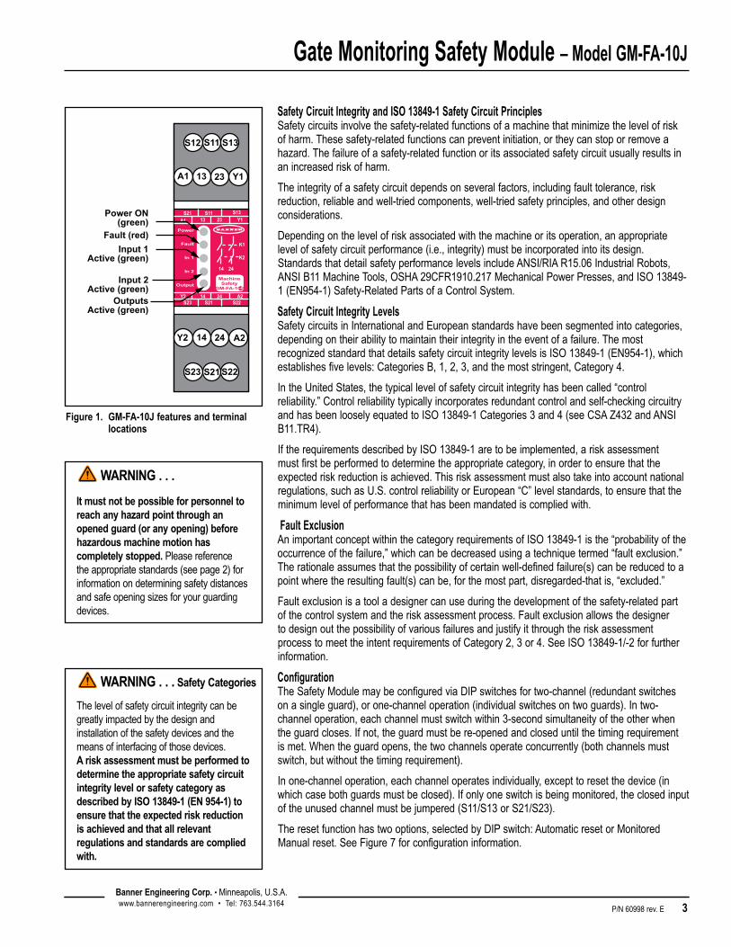
Power ON(green)
Input 1Active (green)
Fault (red)
Input 2Active (green)
OutputsActive (green)
S12 S13 S11
Y12313 A1
A2 2414Y2
S22 S21 S23
Figure 1. GM-FA-10J features and terminal locations
Safety Circuit Integrity and ISO 13849-1 Safety Circuit Principles Safetycircuitsinvolvethesafety-relatedfunctionsofamachinethatminimizethelevelofriskofharm.Thesesafety-relatedfunctionscanpreventinitiation,ortheycanstoporremoveahazard.Thefailureofasafety-relatedfunctionoritsassociatedsafetycircuitusuallyresultsinanincreasedriskofharm.
Theintegrityofasafetycircuitdependsonseveralfactors,includingfaulttolerance,riskreduction,reliableandwell-triedcomponents,well-triedsafetyprinciples,andotherdesignconsiderations.
Dependingonthelevelofriskassociatedwiththemachineoritsoperation,anappropriatelevelofsafetycircuitperformance(i.e.,integrity)mustbeincorporatedintoitsdesign.StandardsthatdetailsafetyperformancelevelsincludeANSI/RIAR15.06IndustrialRobots,ANSIB11MachineTools,OSHA29CFR1910.217MechanicalPowerPresses,andISO13849-1(EN954-1)Safety-RelatedPartsofaControlSystem.
Safety Circuit Integrity LevelsSafetycircuitsinInternationalandEuropeanstandardshavebeensegmentedintocategories,dependingontheirabilitytomaintaintheirintegrityintheeventofafailure.ThemostrecognizedstandardthatdetailssafetycircuitintegritylevelsisISO13849-1(EN954-1),whichestablishesfivelevels:CategoriesB,1,2,3,andthemoststringent,Category4.
IntheUnitedStates,thetypicallevelofsafetycircuitintegrityhasbeencalled“controlreliability.”Controlreliabilitytypicallyincorporatesredundantcontrolandself-checkingcircuitryandhasbeenlooselyequatedtoISO13849-1Categories3and4(seeCSAZ432andANSIB11.TR4).
IftherequirementsdescribedbyISO13849-1aretobeimplemented,ariskassessmentmustfirstbeperformedtodeterminetheappropriatecategory,inordertoensurethattheexpectedriskreductionisachieved.Thisriskassessmentmustalsotakeintoaccountnationalregulations,suchasU.S.controlreliabilityorEuropean“C”levelstandards,toensurethattheminimumlevelofperformancethathasbeenmandatediscompliedwith.
Fault ExclusionAnimportantconceptwithinthecategoryrequirementsofISO13849-1isthe“probabilityoftheoccurrenceofthefailure,”whichcanbedecreasedusingatechniquetermed“faultexclusion.”Therationaleassumesthatthepossibilityofcertainwell-definedfailure(s)canbereducedtoapointwheretheresultingfault(s)canbe,forthemostpart,disregarded-thatis,“excluded.”
Faultexclusionisatooladesignercanuseduringthedevelopmentofthesafety-relatedpartofthecontrolsystemandtheriskassessmentprocess.FaultexclusionallowsthedesignertodesignoutthepossibilityofvariousfailuresandjustifyitthroughtheriskassessmentprocesstomeettheintentrequirementsofCategory2,3or4.SeeISO13849-1/-2forfurtherinformation.
ConfigurationTheSafetyModulemaybeconfiguredviaDIPswitchesfortwo-channel(redundantswitchesonasingleguard),orone-channeloperation(individualswitchesontwoguards).Intwo-channeloperation,eachchannelmustswitchwithin3-secondsimultaneityoftheotherwhentheguardcloses.Ifnot,theguardmustbere-openedandcloseduntilthetimingrequirementismet.Whentheguardopens,thetwochannelsoperateconcurrently(bothchannelsmustswitch,butwithoutthetimingrequirement).
Inone-channeloperation,eachchanneloperatesindividually,excepttoresetthedevice(inwhichcasebothguardsmustbeclosed).Ifonlyoneswitchisbeingmonitored,theclosedinputoftheunusedchannelmustbejumpered(S11/S13orS21/S23).
Theresetfunctionhastwooptions,selectedbyDIPswitch:AutomaticresetorMonitoredManualreset.SeeFigure7forconfigurationinformation.
WARNING . . . Safety Categories
Thelevelofsafetycircuitintegritycanbe greatlyimpactedbythedesignandinstallationofthesafetydevicesandthemeansofinterfacingofthosedevices.A risk assessment must be performed to determine the appropriate safety circuit integrity level or safety category as described by ISO 13849-1 (EN 954-1) to ensure that the expected risk reduction is achieved and that all relevant regulations and standards are complied with.

Gate Monitoring Safety Module – Model GM-FA-10J
4 P/N 60998 rev. E
Banner Engineering Corp. •Minneapolis,U.S.A.www.bannerengineering.com•Tel:763.544.3164
Banner Engineering Corp. •Minneapolis,U.S.A.www.bannerengineering.com•Tel:763.544.3164
TheresetinputalsocanbeusedforanExternalDeviceMonitoring(EDM)circuit.TheEDMcircuitconsistsofanormallyclosed,force-guidedcontactfromeachdevicebeingcontrolledbytheSafetyModule,allwiredinserieswiththeResetbutton(ifused)andterminatedatterminalsY1andY2.SeeFigure6forfurtherinformation.
TheoutputoftheSafetyModuleconsistsoftworedundantoutputswitchingchannels,eachofwhichistheseriesconnectionoftwoforced-guidedrelaycontacts(K1andK2inFigure6).Eachoftheswitchingoutputsisratedforupto250Vacatupto6amps.
Safety Switch RequirementsThefollowinggeneralrequirementsandconsiderationsapplytotheinstallationofinterlockedgatesandguardsforthepurposeofsafeguarding.Inaddition,theusermustrefertotherelevantregulationsandbesuretocomplywithallnecessaryrequirements.
Hazardsguardedbytheinterlockedguardmustbepreventedfromoperatinguntiltheguardisclosed;astopcommandmustbeissuedtotheguardedmachineiftheguardopenswhilethehazardispresent.Closingtheguardmustnot,byitself,initiatehazardousmotion;aseparateproceduremustberequiredtoinitiatethemotion.Thesafetyswitchesmustnotbeusedasamechanicalorend-of-travelstop.
Theguardmustbelocatedanadequatedistancefromthedangerzone(sothehazardhastimetostopbeforetheguardisopenedsufficientlytoprovideaccesstothehazard),anditmustopeneitherlaterallyorawayfromthehazard,notintothesafeguardedarea.Theguardalsoshouldnotbeabletoclosebyitselfandactivatetheinterlockingcircuitry.Theinstallationmustpreventpersonnelfromreachingover,under,aroundorthroughtheguardtothehazard.Anyopeningsintheguardmustnotallowaccesstothehazard(seetheappropriatestandard).Theguardmustbestrongenoughanddesignedtoprotectpersonnelandcontainhazardswithintheguardedareathatcanbeejected,droppedoremittedbythemachine.
Thesafetyswitches,actuators,sensorsandmagnetsusedwiththeSafetyModulemustbedesignedandinstalledsothattheycannotbeeasilydefeated.Theymustbemountedsecurely,sothattheirphysicalpositioncannotshift,usingreliablefastenersthatrequireatooltoremove.Mountingslotsinthehousingsareforinitialadjustmentonly;finalmountingholesmustbeusedforpermanentlocation.
Coded Magnetic Safety Switches: Similartopositive-openingsafetyswitches,codedmagneticswitchesusedwiththeSafetyModulemustprovideonenormallyclosedcontactandonenormallyopencontact(typicallyafour-wireswitch).(SeeBannerSafetyCatalogorpage15formoreinformation.)The sensor and its magnet must be mounted a minimum distance of 15 mm (0.6″) from any magnetized or ferrous materials for proper operation.Ifeitherthesensorormagnetismountedonamaterialthatcanbemagnetized(aferrousmetal,suchasiron),theswitchingdistancewillbeaffected.Althoughthesensorandmagnetarecodedtominimizethepossibilityoffalseactuation,theyshouldnotbeusedwithinknownfieldsofhigh-levelelectromagneticradiation.
Dependingonthemodelofsensorandmagnetused,theinstallationmustbedesignedtoprovidethecorrectdirectionofapproach(seepage17).The speed of approach must be fast enough to meet the simultaneity-monitoring period of 1.0 second, approximately equal to or greater than 0.1 m (4″) per second.Ifthesimultaneityrequirementisnotmet,theSafetyModulecannotberesetandwillnotcloseitssafetyoutputcontacts.
Positive-Opening Interlocking Switches: SafetyinterlockswitchesusedwiththeSafetyModulemustsatisfyseveralrequirements.Eachswitchmustprovideelectricallyisolatedcontacts:atminimum,onenormallyclosed(N.C.)contactornormallyconductingsourceandonenormallyopen(N.O.)contactornormallyOFFsourcetointerfacewiththeModule.
Thecontactsmustbeof“positive-opening”design,withoneormorenormallyclosedcontactsratedforsafety.Positive-openingoperationcausestheswitchtobeforcedopen,withouttheuseofsprings,whentheswitchactuatorisdisengagedormovedfromitshomeposition(seetheBannerSafetyCatalogforexamples).Inaddition,theswitchesmustbemountedina“positivemode,”tomove/disengagetheactuatorfromitshomepositionandopenthenormallyclosedcontact,whentheguardopens.
Gate Monitoring Safety Module – Model GM-FA-10J
P/N 60998 rev. E 5Banner Engineering Corp. •Minneapolis,U.S.A.www.bannerengineering.com•Tel:763.544.3164
Banner Engineering Corp. •Minneapolis,U.S.A.www.bannerengineering.com•Tel:763.544.3164
Switch Hookups, Typical ApplicationsRequirementsvarywidelyforthelevelofcontrolreliabilityorsafetycategory(perISO13849)intheapplicationofinterlockedguards.WhileBannerEngineeringalwaysrecommendsthehighestlevelofsafetyinanyapplication,itistheresponsibilityoftheusertosafelyinstall,operateandmaintaineachsafetysystemandcomplywithallrelevantlawsandregulations.TheapplicationsshowninFigures2,3,and4meetorexceedtherequirementsforcontrolreliabilityandSafetyCategory3or4,perISO13849(EN954-1).
Mechanical Installation
RoutetheswitchcabletotheSafetyModulelocation.TheSafetyModuleisnotdesignedforexposedwiring;houseitinanenclosurewithaNEMA3(orIECIP54)rating,orbetter.TheSafetyModulemaybemounteddirectlyontostandard35mmDINrail.
Heat Dissipation ConsiderationsForreliableoperation,theusermustensurethattheoperatingspecificationsarenotexceeded.Theenclosuremustprovideadequateheatdissipation,sothattheaircloselysurroundingtheModuledoesnotexceedthemaximumoperatingtemperaturestatedintheSpecifications.Methodstoreduceheatbuild-upincludeventing,forcedairflow(e.g.,exhaustfans),adequateenclosureexteriorsurfacearea,andspacingbetweenmodulesandothersourcesofheat.
Electrical Installation
EachSafetyModuleispoweredby24Vac/dc(atlessthan150mA).TheSafetyModule,inturn,suppliespowertoeachswitch.
ItisnotpossibletogiveexactwiringinstructionsforaSafetyModulewhichinterfacestoamultitudeofmachinecontrolconfigurations.Thefollowingguidelinesaregeneralinnature.
TheSafetyModulehasnodelayfunction.Itsoutputrelaycontactsopenwithin35millisecondsafterasafetyinputopens.ThisclassifiestheSafetyModuleasfunctionalstop“Category0”,asdefinedbyANSINFPA79andIEC/EN60204-1.
Connection of Power to the Safety ModuleTheSafetyModulerequiresa24Vac/dcsupplyvoltage(seeSpecifications).Useextremecautionwheneverinstallingacpower.Useaminimumof16to18AWGwireforpowerandoutputconnections.Useaminimumof20AWGwireforallotherterminalconnections.Ahand-operatedsupplydisconnectandover-currentprotection(e.g.,acircuitbreaker)mustbeprovidedperANSINFPA79andIEC/EN60204-1.
SeeFigures2through6forconnectionofsafetyswitches.
Monitoring Series-Connected Safety Switches Whenmonitoringtwoindividuallymountedsafetyswitches(asshowninFigures2,3,and4),afaultyswitchwillbedetectedifitfailstoswitchastheguardopens.Inthiscase,theGateMonitorModulewillde-energizeitsoutputrelaysanddisableitsresetfunctionuntiltheinputrequirementsaremet(i.e.,thefaultyswitchisreplaced).However,whenaseriesofinterlockingsafetyswitchesismonitoredbyasingleSafetyModule,thefailureofoneswitchinthesystemmaybemaskedornotdetectedatall(refertoFigures5and6).
Series-connectedinterlockswitchcircuitsdonotmeetISO13849(EN954-1)SafetyCategory4andmaynotmeetControlReliabilityrequirementsbecauseofthepotentialforaninappropriateGateMonitorresetorapotentiallossofthesafetystopsignal.Amultipleconnectionofthistypeshouldnotbeusedinapplicationswherelossofthesafetystopsignaloraninappropriateresetcanleadpotentiallytoseriousinjuryordeath.Thefollowingtwoscenariosassumetwopositive-openingsafetyswitchesoneachguard:
WARNING . . . Shock Hazard
Always disconnect power from the Safety Module and all power from the machine being controlled before making any connections or replacing any component. ElectricalinstallationandwiringmustbemadebyqualifiedpersonnelandmustcomplywiththeNEC(NationalElectricalCode),ANSINFPA79orIEC60204-1,andallapplicablelocalstandardsandcodes.

Gate Monitoring Safety Module – Model GM-FA-10J
6 P/N 60998 rev. E
Banner Engineering Corp. •Minneapolis,U.S.A.www.bannerengineering.com•Tel:763.544.3164
Banner Engineering Corp. •Minneapolis,U.S.A.www.bannerengineering.com•Tel:763.544.3164
1. Masking of a failure.Ifaguardisopenedbutaswitchfailstoopen,theredundantsafetyswitchwillopenandcausetheSafetyModuletode-energizeitsoutputs.Ifthefaultyguardisthenclosed,bothSafetyModuleinputchannelsalsoclose,butbecauseonechanneldidnotopen,theSafetyModulewillnotreset.However,ifthefaultyswitchisnotreplacedandasecond“good”guardiscycled(openingandthenclosingbothoftheModule’sinputchannels),theModuleconsidersthefailuretobecorrected.Withtheinputrequirementsapparentlysatisfied,theModuleallowsareset.Thissystemisnolongerredundantand,ifthesecondswitchfails,mayresultinanunsafecondition(i.e.,theaccumulationoffaultsresultsinthelossofthesafetyfunction).
2.Non-detection of a failure.Ifagoodguardisopened,theSafetyModule de-energizesitsoutputs(anormalresponse).Butifafaultyguardisthenopenedandclosedbeforethegoodguardisre-closed,thefailureonthefaultyguardisnotdetected.Thissystemisnolongerredundantandmayresultinalossofsafetyifthesecondsafetyswitchfailstoswitchwhenneeded.
Thesystemsineitherscenariodonotinherentlycomplywiththesafetystandardrequirementsofdetectingsinglefaultsandpreventingthenextcycle.Inmultiple-guardsystemsusingseries-connectedsafetyswitches,itisimportanttoperiodicallycheckthefunctionalintegrityofeachinterlockedguardindividually.Operators, maintenance personnel, and others associated with the operation of the machine must be trained to recognize such failures and be instructed to correct them immediately.
OpenandcloseeachguardseparatelywhileverifyingthattheGateMonitoroutputsoperatecorrectlythroughoutthecheckprocedure.Followeachgateclosurewithamanualreset,ifneeded.Ifacontactsetfails,theSafetyModulewillnotenableitsresetfunction.IftheSafetyModuledoesnotreset,aswitchmayhavefailed;thatswitchmustbeimmediatelyreplaced.
Thischeckmustbeperformedandallfaultsmustbecleared,ataminimum,duringperiodiccheckouts.If the application can not exclude these types of failures and such a failure could result in serious injury or death, then the series connection of safety switches must not be used.
Connection to the Guarded Machine Themachineinterfacehookupdiagram(Figure7)showsagenericconnectionoftheModule’stworedundantoutputcircuitstomachineprimarycontrolelementsMPCE1andMPCE2.Amachineprimarycontrolelementisanelectricallypowereddevice,externaltotheModule,whichstopstheguardedmachinerybyimmediatelyremovingelectricalpowertothemachineand(whennecessary)byapplyingbrakingtodangerousmotion.ThestopisaccomplishedbyremovingpowertotheactuatorcoilofeitherMPCE.
TosatisfytheSafetyCategory4requirementsofISO13849(EN954-1),eachMPCEmustofferanormallyclosed,forced-guidedmonitorcontact.OnenormallyclosedmonitorcontactfromeachMPCEiswiredinseriestotheY1-Y2feedback/resetinput(seeFigure7).Inoperation,ifoneoftheswitchingcontactsofeitherMPCEfailsintheshortedcondition,theassociatedmonitorcontactwillremainopen,preventingtheresetoftheModule.
External Device MonitoringTosatisfytherequirementsofControlReliability(OSHAandANSI)andCategory3and4ofISO13849-1(EN954-1),themachineprimarycontrolelements(MPCEs)musteachofferanormallyclosed,forced-guided(mechanicallylinked)monitorcontact.ConnectonenormallyclosedmonitorcontactfromeachmasterstopcontrolelementinseriestoY1andY2(seehookupdrawings).
Inoperation,ifoneoftheswitchingcontactsofeitherMPCEfailsintheenergizedcondition,theassociatedmonitorcontactwillremainopen.Therefore,itwillnotbepossibletoresettheSafetyModule.IfnoMPCE-monitorcontactsaremonitored,ajumpermustbeinstalledbetweenterminalsY1andY2(dottedline),asshowninthehookupdrawings.It is the user’s responsibility to ensure that any single failure will not result in a hazardous condition and will prevent a successive machine cycle.
WARNING . . . Mutiple Switching Devices
Whenever two or more switches are connected to the same Safety Module:•Contacts of the corresponding pole
of each switch must be connected together in series. Never connect the contacts of multiple emergency-stop switches in parallel to one Module. SuchaparallelconnectiondefeatstheswitchcontactmonitoringabilityoftheModuleandcreatesanunsafeconditionwhichcouldresutinseriousinjuryordeath.
•Each switch must be individually actuated (engaged), then re-armed and the Safety Module reset. ThisallowstheModuletocheckeachswitchanditswiringtodetectfaults.
Failure to test each switch individually in this manner could result in undetected faults and create an unsafe condition which could result in serious injury or death. Thischeckmustbeperformedduringperiodiccheckouts.
Gate Monitoring Safety Module – Model GM-FA-10J
P/N 60998 rev. E 7Banner Engineering Corp. •Minneapolis,U.S.A.www.bannerengineering.com•Tel:763.544.3164
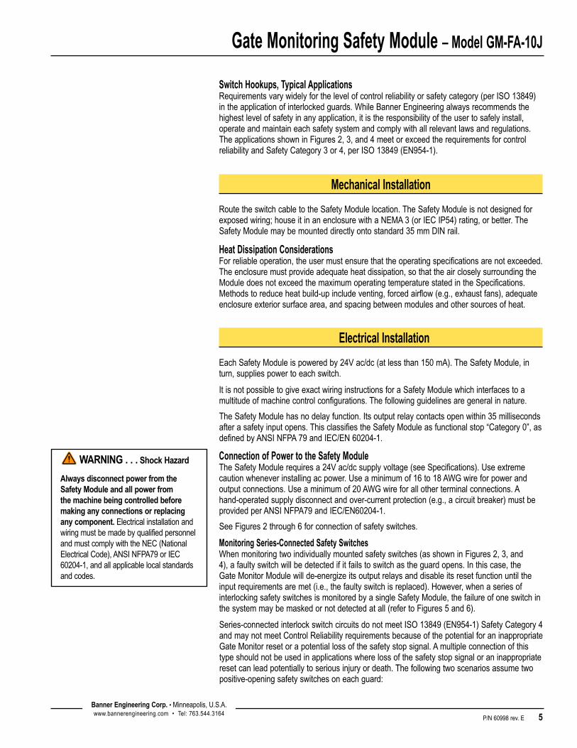
Figure 2. Hookup to two 4-wire coded magnetic safety switches
Guard
Mechanicalstop
Mechanicalstop
open
S12 S13S11
S23 S22S21
Guard #1
NOTE: Guard shown in closed position.
Figure 3. Hookup to two positive-opening safety interlock switches
Two-Channel Monitoring Configured for two-channel monitoring of one guard. This application is considered to meet or exceed requirements for Control Reliability and Safety Categories 3 and 4 per ISO 13849-1 (EN954-1).
Mechanical stop
Guard #1open
Guard #2open
BlueGray
Black
Brown
SI-MAG..SM SI-MAG..MM
SI-MAG..SM SI-MAG..MM
Mechanical stop
BlueGray
Black
Brown
NOTE: If only one magnetic safety switch is used, select 1-channel input and jumper S23 to S21.
S12 S13S11
S23 S22S21
One-Channel Monitoring Configured for one-channel monitoring of either one or two guards. This application is considered to meet or exceed requirements for Control Reliability and Safety Categories 3 and 4 per ISO 13849-1 (EN954-1).
S12 S13
S23 S22
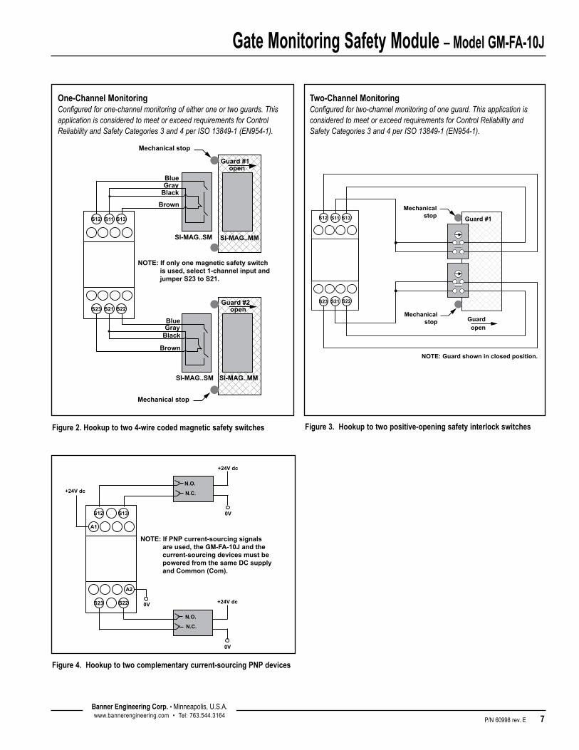
NOTE: If PNP current-sourcing signals are used, the GM-FA-10J and the current-sourcing devices must be powered from the same DC supply and Common (Com).
A1
A2
+24V dc
0V
+24V dc
+24V dc
N.O.
N.C.
N.O.
N.C.
0V
0V
Figure 4. Hookup to two complementary current-sourcing PNP devices
Gate Monitoring Safety Module – Model GM-FA-10J
8 P/N 60998 rev. E
Banner Engineering Corp. •Minneapolis,U.S.A.www.bannerengineering.com•Tel:763.544.3164
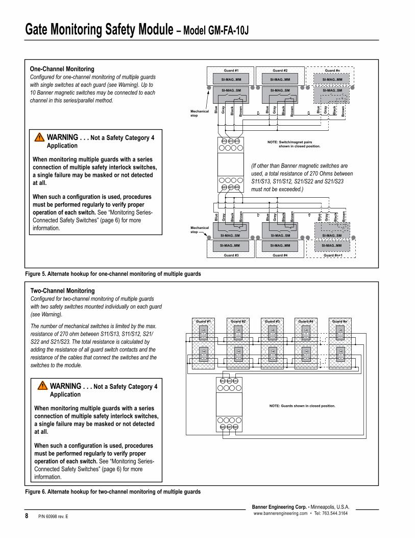
Figure 5. Alternate hookup for one-channel monitoring of multiple guards
Blu
e
Gra
y
Bla
ck
Bro
wn
Blu
e
Gra
y
Bla
ck
Bro
wn
Blu
e
Gra
y
Bla
ck
Bro
wn
Blu
e
Gra
y
Bla
ck
Bro
wn
Blu
e
Gra
y
Bla
ck
Bro
wn
Blu
e
Gra
y
Bla
ck
Bro
wn
S12 S13S11
S23 S22S21
SI-MAG..SM SI-MAG..SM SI-MAG..SM
Guard #1 Guard #2 Guard #n
SI-MAG..SM SI-MAG..SM SI-MAG..SM
Guard #3 Guard #4 Guard #n+1
NOTE: Switch/magnet pairs shown in closed position.
Mechanical stop
Mechanical stop
SI-MAG..MMSI-MAG..MM SI-MAG..MM
SI-MAG..MM SI-MAG..MM SI-MAG..MM
One-Channel Monitoring Configured for one-channel monitoring of multiple guards with single switches at each guard (see Warning). Up to 10 Banner magnetic switches may be connected to each channel in this series/parallel method.
(If other than Banner magnetic switches are used, a total resistance of 270 Ohms between S11/S13, S11/S12, S21/S22 and S21/S23 must not be exceeded.)
Guard #1 Guard #2 Guard #3 Guard #n
NOTE: Guards shown in closed position.
S12 S13S11
S23 S22S21
Guard #4
Figure 6. Alternate hookup for two-channel monitoring of multiple guards
Two-Channel Monitoring Configured for two-channel monitoring of multiple guards with two safety switches mounted individually on each guard (see Warning).
The number of mechanical switches is limited by the max. resistance of 270 ohm between S11/S13, S11/S12, S21/S22 and S21/S23. The total resistance is calculated by adding the resistance of all guard switch contacts and the resistance of the cables that connect the switches and the switches to the module.
WARNING . . . Not a Safety Category 4 Application
When monitoring multiple guards with a series connection of multiple safety interlock switches, a single failure may be masked or not detected at all.
When such a configuration is used, procedures must be performed regularly to verify proper operation of each switch. See“MonitoringSeries-ConnectedSafetySwitches”(page6)formoreinformation.
Gate Monitoring Safety Module – Model GM-FA-10J
P/N 60998 rev. E 9Banner Engineering Corp. •Minneapolis,U.S.A.www.bannerengineering.com•Tel:763.544.3164
Banner Engineering Corp. •Minneapolis,U.S.A.www.bannerengineering.com•Tel:763.544.3164
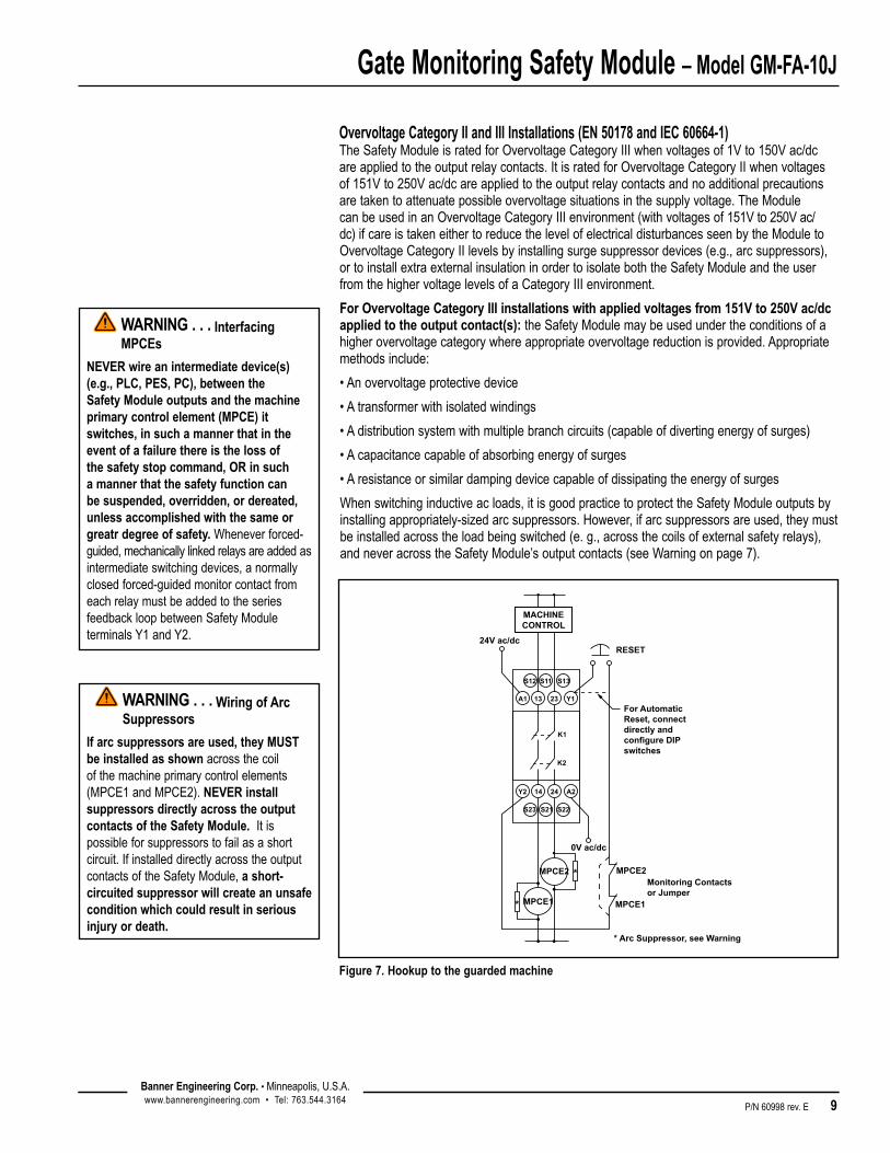
Overvoltage Category II and III Installations (EN 50178 and IEC 60664-1)TheSafetyModuleisratedforOvervoltageCategoryIIIwhenvoltagesof1Vto150Vac/dc areappliedtotheoutputrelaycontacts.ItisratedforOvervoltageCategoryIIwhenvoltagesof151Vto250Vac/dcareappliedtotheoutputrelaycontactsandnoadditionalprecautionsaretakentoattenuatepossibleovervoltagesituationsinthesupplyvoltage.TheModulecanbeusedinanOvervoltageCategoryIIIenvironment(withvoltagesof151Vto250Vac/dc)ifcareistakeneithertoreducethelevelofelectricaldisturbancesseenbytheModuletoOvervoltageCategoryIIlevelsbyinstallingsurgesuppressordevices(e.g.,arcsuppressors),ortoinstallextraexternalinsulationinordertoisolateboththeSafetyModuleandtheuserfromthehighervoltagelevelsofaCategoryIIIenvironment.
For Overvoltage Category III installations with applied voltages from 151V to 250V ac/dc applied to the output contact(s):theSafetyModulemaybeusedundertheconditionsofahigherovervoltagecategorywhereappropriateovervoltagereductionisprovided.Appropriatemethodsinclude:
•Anovervoltageprotectivedevice
•Atransformerwithisolatedwindings
•Adistributionsystemwithmultiplebranchcircuits(capableofdivertingenergyofsurges)
•Acapacitancecapableofabsorbingenergyofsurges
•Aresistanceorsimilardampingdevicecapableofdissipatingtheenergyofsurges
Whenswitchinginductiveacloads,itisgoodpracticetoprotecttheSafetyModuleoutputsbyinstallingappropriately-sizedarcsuppressors.However,ifarcsuppressorsareused,theymustbeinstalledacrosstheloadbeingswitched(e.g.,acrossthecoilsofexternalsafetyrelays),andneveracrosstheSafetyModule’soutputcontacts(seeWarningonpage7).
*
*
* Arc Suppressor, see Warning
A1 Y1
24V ac/dc
MACHINECONTROL
RESET
S12 S13S11
S23 S22S21
2313
Y2 A22414
K1
K2
0V ac/dc
MPCE2Monitoring Contactsor Jumper
MPCE1 MPCE1
For AutomaticReset, connectdirectly and configure DIPswitches
MPCE2
Figure 7. Hookup to the guarded machine
WARNING . . . Interfacing MPCEs
NEVER wire an intermediate device(s) (e.g., PLC, PES, PC), between the Safety Module outputs and the machine primary control element (MPCE) it switches, in such a manner that in the event of a failure there is the loss of the safety stop command, OR in such a manner that the safety function can be suspended, overridden, or dereated, unless accomplished with the same or greatr degree of safety. Wheneverforced-guided,mechanicallylinkedrelaysareaddedasintermediateswitchingdevices,anormallyclosedforced-guidedmonitorcontactfromeachrelaymustbeaddedtotheseriesfeedbackloopbetweenSafetyModuleterminalsY1andY2.
WARNING . . . Wiring of Arc Suppressors
If arc suppressors are used, they MUST be installed as shownacrossthecoilofthemachineprimarycontrolelements(MPCE1andMPCE2).NEVER install suppressors directly across the output contacts of the Safety Module.Itispossibleforsuppressorstofailasashortcircuit.IfinstalleddirectlyacrosstheoutputcontactsoftheSafetyModule,a short-circuited suppressor will create an unsafe condition which could result in serious injury or death.
Gate Monitoring Safety Module – Model GM-FA-10J
10 P/N 60998 rev. E
Banner Engineering Corp. •Minneapolis,U.S.A.www.bannerengineering.com•Tel:763.544.3164
Banner Engineering Corp. •Minneapolis,U.S.A.www.bannerengineering.com•Tel:763.544.3164
Configuration
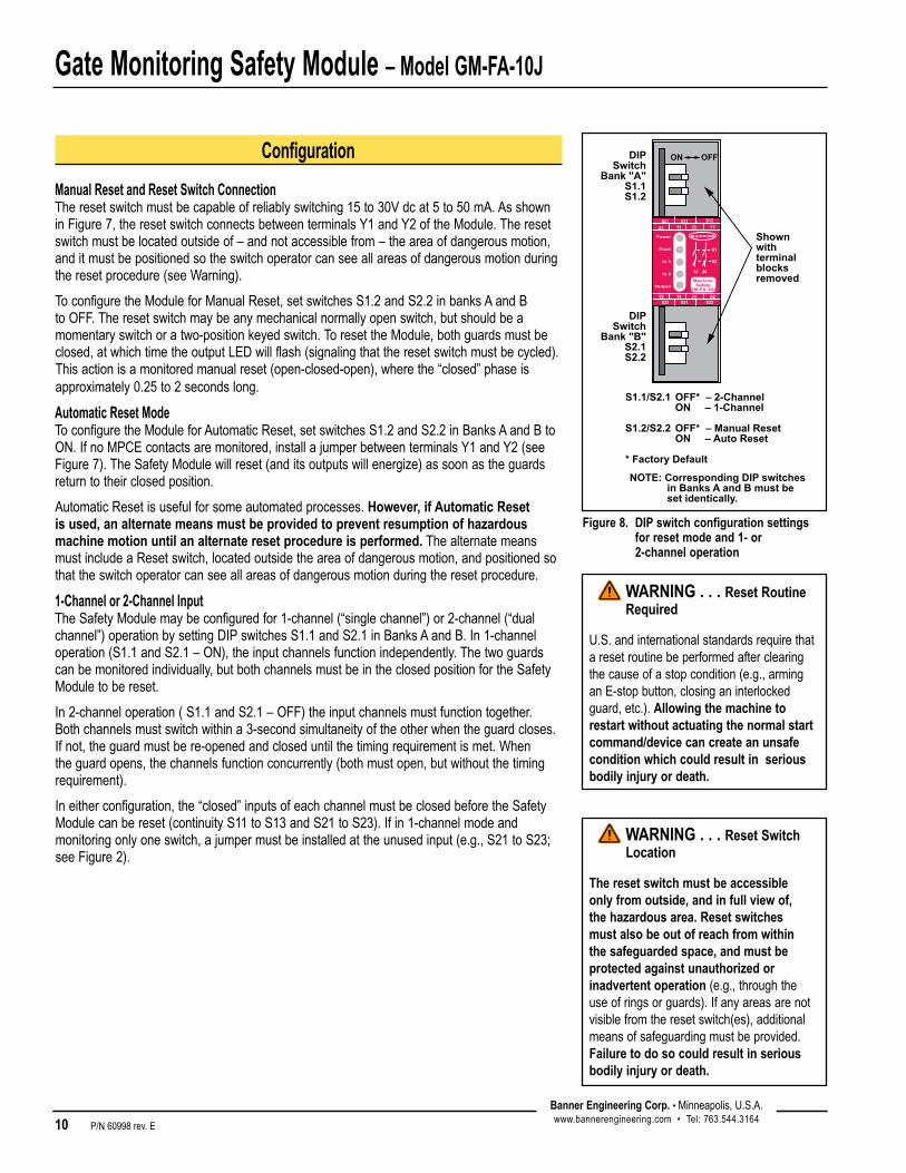
Manual Reset and Reset Switch Connection Theresetswitchmustbecapableofreliablyswitching15to30Vdcat5to50mA.AsshowninFigure7,theresetswitchconnectsbetweenterminalsY1andY2oftheModule.Theresetswitchmustbelocatedoutsideof–andnotaccessiblefrom–theareaofdangerousmotion,anditmustbepositionedsotheswitchoperatorcanseeallareasofdangerousmotionduringtheresetprocedure(seeWarning).
ToconfiguretheModuleforManualReset,setswitchesS1.2andS2.2inbanksAandBtoOFF.Theresetswitchmaybeanymechanicalnormallyopenswitch,butshouldbeamomentaryswitchoratwo-positionkeyedswitch.ToresettheModule,bothguardsmustbeclosed,atwhichtimetheoutputLEDwillflash(signalingthattheresetswitchmustbecycled).Thisactionisamonitoredmanualreset(open-closed-open),wherethe“closed”phaseisapproximately0.25to2secondslong.
Automatic Reset ModeToconfiguretheModuleforAutomaticReset,setswitchesS1.2andS2.2inBanksAandBtoON.IfnoMPCEcontactsaremonitored,installajumperbetweenterminalsY1andY2(seeFigure7).TheSafetyModulewillreset(anditsoutputswillenergize)assoonastheguardsreturntotheirclosedposition.
AutomaticResetisusefulforsomeautomatedprocesses.However, if Automatic Reset is used, an alternate means must be provided to prevent resumption of hazardous machine motion until an alternate reset procedure is performed.ThealternatemeansmustincludeaResetswitch,locatedoutsidetheareaofdangerousmotion,andpositionedsothattheswitchoperatorcanseeallareasofdangerousmotionduringtheresetprocedure.
1-Channel or 2-Channel InputTheSafetyModulemaybeconfiguredfor1-channel(“singlechannel”)or2-channel(“dualchannel”)operationbysettingDIPswitchesS1.1andS2.1inBanksAandB.In1-channeloperation(S1.1andS2.1–ON),theinputchannelsfunctionindependently.Thetwoguardscanbemonitoredindividually,butbothchannelsmustbeintheclosedpositionfortheSafetyModuletobereset.
In2-channeloperation(S1.1andS2.1–OFF)theinputchannelsmustfunctiontogether.Bothchannelsmustswitchwithina3-secondsimultaneityoftheotherwhentheguardcloses.Ifnot,theguardmustbere-openedandcloseduntilthetimingrequirementismet.Whentheguardopens,thechannelsfunctionconcurrently(bothmustopen,butwithoutthetimingrequirement).
Ineitherconfiguration,the“closed”inputsofeachchannelmustbeclosedbeforetheSafetyModulecanbereset(continuityS11toS13andS21toS23).Ifin1-channelmodeandmonitoringonlyoneswitch,ajumpermustbeinstalledattheunusedinput(e.g.,S21toS23;seeFigure2).
Figure 8. DIP switch configuration settings for reset mode and 1- or 2-channel operation
S21A1
S11 S13
S23 S21 S22
13 23 Y1
Y2 14 24 A2
K1
K2
14 24
MachineSafety
GM-FA-10J
Power
Fault
In 1
In 2
Output
DIPSwitch
Bank "A"S1.1S1.2
DIPSwitch
Bank "B"S2.1S2.2
S1.1/S2.1 OFF* – 2-Channel ON – 1-Channel
S1.2/S2.2 OFF* – Manual Reset ON – Auto Reset
* Factory Default
NOTE: Corresponding DIP switches in Banks A and B must be set identically.
OFFON
Shownwithterminalblocksremoved
WARNING . . . Reset Routine Required
U.S.andinternationalstandardsrequirethataresetroutinebeperformedafterclearingthecauseofastopcondition(e.g.,arminganE-stopbutton,closinganinterlockedguard,etc.).Allowing the machine to restart without actuating the normal start command/device can create an unsafe condition which could result in serious bodily injury or death.
WARNING . . . Reset Switch Location
The reset switch must be accessible only from outside, and in full view of, the hazardous area. Reset switches must also be out of reach from within the safeguarded space, and must be protected against unauthorized or inadvertent operation (e.g.,throughtheuseofringsorguards).Ifanyareasarenotvisiblefromtheresetswitch(es),additionalmeansofsafeguardingmustbeprovided.Failure to do so could result in serious bodily injury or death.

Gate Monitoring Safety Module – Model GM-FA-10J
P/N 60998 rev. E 11Banner Engineering Corp. •Minneapolis,U.S.A.www.bannerengineering.com•Tel:763.544.3164
Banner Engineering Corp. •Minneapolis,U.S.A.www.bannerengineering.com•Tel:763.544.3164
Initial Checkout Procedure
1. Removepowerfromthemachineprimarycontrolelements(MPCEs).
2. Closeallmonitoredguards.IftheModuleiswiredto1-channelinput,thesecondinput(S21/S23orS11/S13)mustbejumperedifunused.
3.Applyinputpower(only)totheGateMonitorModuleatterminalsA1andA2(seeFigure7).ThefollowingLEDsshouldcomeON: Power Input1 Input2
IfthePowerLEDcomesON,buteitherorbothInputLEDsarenotON,disconnectinputpowerandcheckthewiringoftheconnectedswitch(es)and/orthejumper.Checkifthejumperisinstalledcorrectlyontheunusedinput.Returntostep2afterthecauseoftheproblemhasbeencorrected.
4. If the Module is set to 1-channel operation:AfterthePower,Input1,andInput2LEDsallareON,openandcloseallconnectedguardsoneatatime.Wheneachindividualguardopens,thecorrespondingInputLEDmustturnOFF,andwhentheguardclosesitsLEDmustcomeONagain.
If the Module is set to 2-channel operation:AfterthePower,Input1,andInput2LEDsallareON,opentheguard;bothswitchesmustopenwithin3seconds,andbothInputLEDsmustturnOFF.IftheredFaultLEDcomesON,simultaneitybetweentheswitchesorwithinoneswitch(betweenitsNOandNCcontacts)wasnotmet.Checkallwiringandtheswitches.
If the Module is set to Auto Reset:(Y1/Y2closedandDIPswitchessettoAutoReset),theoutputLEDwillcomeONassoonasbothInputLEDsareON(outputcontacts13/14and23/24close).
If the Module is set to Manual Monitored Reset:theOutputLEDshouldcomeONonlyifInput1and2LEDsareONandtheResetbuttonconnectedtoY1andY2wentfromopentoclosedandbacktoopenposition.
5. Repeatstep4individuallyforeachguardthatisbeingmonitored.
6. Closetheguard.ApplypowertothemachinecontrolelementsandperformthePeriodicCheckoutProcedureonpage12.
NOTE:MakesurethatbothInput1and2LEDsareONonly when ALL connected guards are closed.IftheguardsareclosedandtheInputLEDsareOFF,theguardswitchesmaybewiredincorrectly,whichcouldresettheModuleinappropriately(safetyoutputcontactscloseassoonasoneoftheconnectedguardsopens).
Donotcontinueoperationuntilallchecksarecompletedandallproblemsarecorrected.SeetheWarningonpage12,andRepairandTroubleshootingonpages18and19forfurtherinformation.
To remove a terminal block, insert a small screwdriver into the slot as shown, and pry to loosen.
When reinserting the block, take care to slide the dovetail on the terminal block into the slot on the frame.
Figure 9. Removal of terminal blocks
CAUTION . . . Disconnect Power Prior to Checkout
Before performing the initial checkout procedure, make certain all power is disconnected from the machine to be controlled.DangerousvoltagesmaybepresentalongtheE-stopSafetyModulewiringbarrierswheneverpowertothemachinecontrolelementsisON.Exercise extreme caution whenever machine control power is or may be present. Always disconnect power to the machine control elements before opening the enclosure housing of the Safety Module.
WARNING . . . Multiple Safety Devices
When two or more safety devices are used, each device must be individually actuated, causing a STOP or open-contact condition, then reset/rearmed and the Safety Module reset (ifusingmanualresetmode).Thisallowsthemonitoringcircuitstocheckeachdeviceanditswiringtodetectfaults.Failure to test each device in this way could result in undetected faults and create an unsafe condition. This could result in serious bodily injury or death.

Gate Monitoring Safety Module – Model GM-FA-10J
12 P/N 60998 rev. E
Banner Engineering Corp. •Minneapolis,U.S.A.www.bannerengineering.com•Tel:763.544.3164
Banner Engineering Corp. •Minneapolis,U.S.A.www.bannerengineering.com•Tel:763.544.3164
Periodic Checks
Ateachshiftchangeormachinesetup,aDesignatedPerson*shoulddothefollowingchecksonallsafetyswitches:
1.Breakageordamageoftheswitch,sensor,actuator,ormagnet.
2.Goodalignmentbetweentheswitchandactuatororsensorandmagnet.
3.Confirmationthattheswitchesarenotbeingusedasanend-of-travelstop.
4.Looseningofthemountinghardware.
5.Verificationthatitisnotpossibletoreachanyhazardpointthroughanopenedguard(oranyopening)beforehazardousmachinemotionstopscompletely.
6.OpenandcloseeachguardseparatelywhileverifyingthattheGateMonitoroutputsoperatecorrectlythroughoutthecheckprocedure.Followeachgateclosurewithamanualreset,ifneeded.Ifacontactsetfails,theSafetyModulewillnotenableitsresetfunction.IftheSafetyModuledoesnotreset,aswitchmayhavefailed;thatswitchmustbeimmediatelyreplaced.
Inaddition,aQualifiedPerson*shoulddothefollowingonaperiodicschedule(determinedbytheuser,basedupontheseverityoftheenvironmentandthefrequencyofswitchactuations):
1.Inspecttheelectricalwiringforcontinuityanddamage.
2.Confirmthatwiringconformstotheinstructionsgiveninthisinstallationmanual.
Donotcontinueoperationuntilallchecksarecompletedandallproblemsarecorrected.SeeRepairandTroubleshootingonpages18and19forfurtherinformation.
*ADesignatedPersonisidentifiedinwritingbytheemployerasbeingappropriatelytrainedtoperformaspecifiedcheckoutprocedure.AQualifiedPersonpossessesarecognizeddegreeorcertificateorhasextensiveknowledge,training,andexperiencetobeabletosolveproblemsrelatingtosafetyswitchinstallation.
WARNING . . . Do Not Use Machine Until System Is Working Properly
Ifallofthesecheckscannotbeverified,donotattempttousetheguardedmachineuntilthedefectorproblemhasbeencorrected.
Attempts to use the guarded machine under such conditions could result in serious bodily injury or death.

Gate Monitoring Safety Module – Model GM-FA-10J
P/N 60998 rev. E 13Banner Engineering Corp. •Minneapolis,U.S.A.www.bannerengineering.com•Tel:763.544.3164
Banner Engineering Corp. •Minneapolis,U.S.A.www.bannerengineering.com•Tel:763.544.3164
Supply Voltage and Current 24Vdc±15%@150mA(SELV-ratedsupplyaccordingtoENIEC60950,NECClass2)24Vac±15%@150mA,50-60Hz+/-5%(NECClass2-ratedtransformer)Power consumption: approx.3VA/3W TocomplywithULandCSAstandards,theisolatedsecondarypowersupplycircuitintheinstallationmustincorporateamethodtolimittheovervoltageto0.8kV.
Supply Protection Circuitry Protectedagainsttransientvoltagesandreversepolarity
Overvoltage Category Output relay contact voltage of 1V to 150V ac/dc: CategoryIII Output relay contact voltage of 151V to 250V ac/dc: CategoryII(CategoryIII,ifappropriateovervoltagereductionisprovided,asdescribedonpage9.)
Pollution Degree 2
Output Configuration Eachnormallyopenoutputchannelisaseriesconnectionofcontactsfromtwoforced-guided(mechanicallylinked)relays,K1-K2.Contacts:AgNi,5µmgold-platedLo w Current Rating:The5µmgold-platedcontactsallowtheswitchingoflowcurrent/lowvoltage.Inthese
low-powerapplications,multiplecontactscanalsobeswitchedinseries(e.g.,“dryswitching”). To preserve the gold plating on the contacts, do not exceed the following max. values at any time: Min. voltage: 1Vac/dc Max. voltage:60V Min. current:5mAac/dc Max. current:300mA Min. power:5mW(5mVA) Max. power:7W(7VA)Hi gh Current Rating:Ifhigherloadsmustbeswitchedthroughoneormoreofthecontacts,theminimum
andmaximumvaluesofthecontact(s)changesto:
Mechanical life: ≥50,000,000operationsElectrical life (switching cycles of the output contacts, resistive load): 150,000cycles@900VA; 1,000,000cycles@250VA;2,000,000cycles@150VA;5,000,000cycles@100VANOTE: Transient suppression is recommended when switching inductive loads. Install suppressors
across load. Never install suppressors across output contacts (see Warning, page 9).
Output Response Time 35msmax.
Input Requirements Eachswitchorsensormusthaveanormallyclosedcontactandanormallyopencontactcapableofswitching20to50mA@15to30Vdc.
Reset switch:20mA@12Vdc,hardcontactonly
Max. external resistance between terminals S11/S12, S11/S13, S21/S22 and S21/S23: 270ohmseach.
Simultaneity Monitoring 2-Channel operation:3seconds1-Channel operation: infinite
Status Indicators 1 red LED:Fault(see“Troubleshooting,”page18)4 green LEDs:Power–powerissuppliedtoSafetyModuleChannel1–inputssatisfied(guardclosed)Channel2–inputssatisfied(guardclosed)Output–K1andK2energized,safetyoutputsclosed
Construction Polycarbonatehousing.RatedIECIP20
Mounting Mountstostandard35mmDINrailtrack.SafetyModulemustbeinstalledinsideanenclosureratedNEMA3(IECIP54),orbetter.
Specifications
Emergency Stop Device 29YL
Minimum: Voltage: 15Vac/dcCurrent:30mAac/dc Power:0.45W(0.45VA)
Maximum: 250Vac/24Vdc,6Aresistive B300,R300perUL508
Minimum: Voltage: 15Vac/dcCurrent:30mAac/dc Power:0.45W(0.45VA)
Maximum: 250Vac/24Vdc,6Aresistive IEC60947-5-1: AC15:230Vac,3A;DC-13:24Vdc,2A
Gate Monitoring Safety Module – Model GM-FA-10J
14 P/N 60998 rev. E
Banner Engineering Corp. •Minneapolis,U.S.A.www.bannerengineering.com•Tel:763.544.3164
Banner Engineering Corp. •Minneapolis,U.S.A.www.bannerengineering.com•Tel:763.544.3164
S12A1
S11 S13
S23 S21 S22
13 23 Y1
Y2 14 24 A2
K1
K2
14 24
MachineSafety
GM-FA-10I
Power
Fault
In 1
In 2
Output
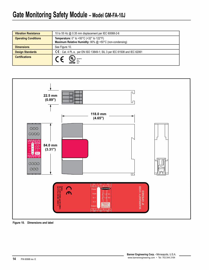
118.0 mm(4.65")
84.0 mm(3.31")
22.5 mm(0.89")
Figure 10. Dimensions and label
Vibration Resistance [email protected]
Operating Conditions Temperature:0°to+50°C(+32°to122°F)Maximum Relative Humidity:90%@+50°C(non-condensing)
Dimensions SeeFigure10.
Design Standards :Cat.4PLe,perENISO13849-1;SIL3perIEC61508andIEC62061
CertificationsEmergency Stop Device 29YL

Gate Monitoring Safety Module – Model GM-FA-10J
P/N 60998 rev. E 15Banner Engineering Corp. •Minneapolis,U.S.A.www.bannerengineering.com•Tel:763.544.3164
Banner Engineering Corp. •Minneapolis,U.S.A.www.bannerengineering.com•Tel:763.544.3164
Magnet / Sensor PairMagnet Sensor*
Coded Magnet Sensor Cable
Switching Distance Min. ON Max. OFF
SI-MAG1SMSI-MAG1SMCO†
SI-MAG1MMSI-MAG1MM90††
3m(10')
3mm(0.12") 14mm(0.55")
SI-MAG1MMHF 8mm(0.31") 16mm(0.63")
SI-MAG2SM SI-MAG2MM 4mm(0.16") 8mm(0.32")
SI-MAG3SM SI-MAG3MM 3mm(0.12") 7mm(0.28")
Magnetic Switch Models
*9m(30')cablesareavailableformagnetsensorsbyaddingsuffix“w/30”tothemodelnumber(e.g.,SI-MAG1SM w/30).
†CableoppositeseeFigure11b,page16)††90°orientation(seeFigure14a,page17)
Magnetic Switch SpecificationsSwitching Elements Threepole-stablereedswitches
Repeat Switching Accuracy ±0.1mm(±0.004")
Construction Epoxy-encapsulatedcircuitinpolyamidehousing
Environmental Rating NEMA4X,IECIP67
Switching Capacity [email protected](27Ωfuseresistorin-line,eachchannel)
Operating Temperature -5°to+70°C(+23°to+158°F)
ConnectionsIntegralPVC-jacketed3m(10')4-wirecable.CableO.D.is5mm(0.2").Wiresare24AWG(0.25mm²).
HardwareAllmountinghardwareissuppliedbyuser.Useofpermanentfastenersorlockinghardwareisrecommendedtopreventlooseningordisplacementoftheactuatorandswitchbody.MountingholesinthemagnetandsensoracceptM4(#6)hardware(seeFigures11,12,and13).
Application NoteThesensor/magnetpairmustbemountedaminimumdistanceof15mm(0.6”)fromanymagnetizedorferrousmaterials.MultipleSFA-IMB1(usedwithSI-MAG1..)andSFA-IMB2(usedwithSI-MAG2..)canbeusedasspacers.
Accessories

Gate Monitoring Safety Module – Model GM-FA-10J
16 P/N 60998 rev. E
Banner Engineering Corp. •Minneapolis,U.S.A.www.bannerengineering.com•Tel:763.544.3164
43 mm(1.69")
22 mm(0.87")
7 mm(0.28")
26 mm(1.02")
ø 8.3 mm(0.33") (2)
ø 4.3 mm(0.17") (2)
SensingSurface
29 mm(1.14")
13 mm(0.51")
4.5 mm(0.18")
88 mm(3.46")
78 mm(3.07")
68 mm(2.68")
4.5 mm(0.18") (3)
6.5 mm(0.26")
25 mm(0.98")
10.7 mm(0.42")
7.2 mm(0.28")2.5 mm(0.10")
13 mm(0.51")
SensingSurface
3.0 mm(0.12")
43 mm(1.69")
22 mm(0.87")
7 mm(0.28")
26 mm(1.02")
ø 8.3 mm(0.33") (2)
ø 4.3 mm(0.17") (2)
MagnetSurface
29 mm(1.14")
13 mm(0.51")
4.5 mm(0.18")
88 mm(3.46")
78 mm(3.07")
68 mm(2.68")
4.5 mm(0.18") (3)
6.5 mm(0.26")
25 mm(0.98")
10.7 mm(0.42")
7.2 mm(0.28")2.5 mm(0.10")
13 mm(0.51")
MagnetSurface
3.0 mm(0.12")
Figure 11a. SI-MAG1SM Sensor
88 mm(3.46")
78 mm(3.07")
68 mm(2.68")
4.5 mm(0.18") (3)
6.5 mm(0.26")
25 mm(0.98")
10.7 mm(0.42")
7.2 mm(0.28")
2.5 mm(0.10")
13 mm(0.51")
SensingSurface
3.0 mm(0.12")
Figure 11b. SI-MAG1SMCO Sensor Figure 11c. SI-MAG1MM/MM90/MMHF Magnet
35 mm(1.38")
34 mm(1.34")
2 mm(0.08")
SW365.2 mm
(0.2")
27.5 mm (1.06")
M30 x 1.5 mm
SensingSurface
ø 35 mm (1.38")
15 mm (0.59")
9 mm (0.35")
35 mm(1.38")
25 mm(0.98")
4.5 mm (0.18")
10.5 mm(0.41")Magnet
Surface
Figure 13a. SI-MAG3SM Sensor Figure 13b. SI-MAG3MM Magnet
Figure 12a. SI-MAG2SM Sensor Figure 12b. SI-MAG2MM Magnet
Magnetic Switch Dimensions

Gate Monitoring Safety Module – Model GM-FA-10J
P/N 60998 rev. E 17Banner Engineering Corp. •Minneapolis,U.S.A.www.bannerengineering.com•Tel:763.544.3164
Direction ofMovement
Alternate Direction of Approachmovement is parallel to theplane of the sensing face
Important! The magnet mounting holes must be orientedas shown, relative to the sensor cable position.
CodedMagnet
MagnetSensor
Normal Direction of Approachmovement is perpendicular to theplane of the sensing face
Direction ofMovement
Important! The magnet mounting holes must be orientedas shown, relative to the sensor cable position.
CodedMagnetMagnet
Sensor
Direction ofMovement
Incorrect Magnet Orientation
CodedMagnet
MagnetSensor
“Direction of Approach” Options for Sensor/Magnet Pairs
Direction ofMovement
Incorrect Direction of ApproachLabel to label approach of sensor and magnet is notpossible
Direction ofMovement
Incorrect Direction of Approach90º approach of sensor and magnet is not possible
Incorrect Direction of ApproachLabel to label approach of sensor and magnet is not possible
Direction ofMovement
Sensing face
CodedMagnet
Normal Direction of Approachmovement is perpendicular to theplane of the sensing face
Direction ofMovement
MagnetSensor
Incorrect Direction of Approach90º approach of sensor and magnet is not possible
Direction ofMovement
Alternate Direction of Approachmovement is parallel to theplane of the sensing face
Direction ofMovement
CodedMagnet
MagnetSensor
Direction ofMovement
Alternate Direction of Approachmovement is parallel to theplane of the sensing face
Direction ofMovement
Normal Direction of Approachmovement is perpendicular to theplane of the sensing face
CodedMagnet
MagnetSensor
Figure 14a. Direction of Approach for SI-MAG1.. sensor/magnet pairs
Figure 14b. Direction of Approach for SI-MAG2.. sensor/magnet pairs
Figure 14c. Direction of Approach for SI-MAG3.. sensor/magnet pairs
NOTE:Forallmagnetstyleswitches,approachspeedmustbegreaterthan0.1m/stoallowforproperswitching.(Seepage4.)
Gate Monitoring Safety Module – Model GM-FA-10J
18 P/N 60998 rev. E
Banner Engineering Corp. •Minneapolis,U.S.A.www.bannerengineering.com•Tel:763.544.3164
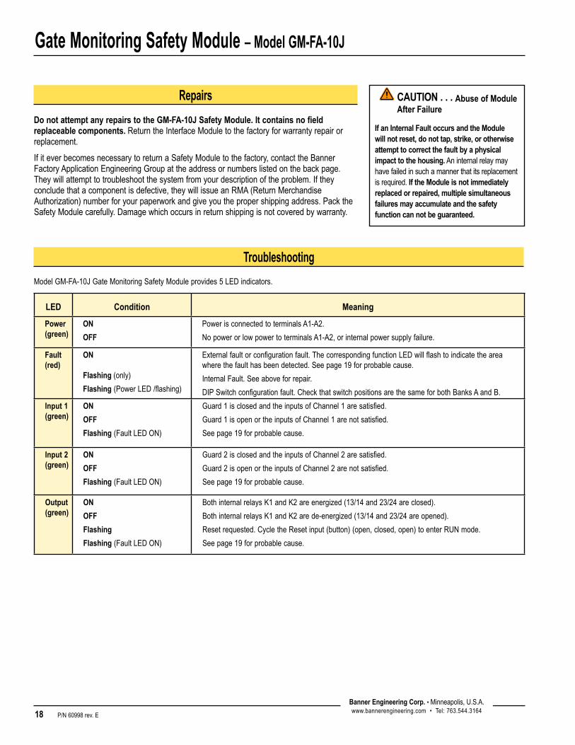
Troubleshooting
ModelGM-FA-10JGateMonitoringSafetyModuleprovides5LEDindicators.
LED Condition Meaning
Power(green)
ON
OFF
PowerisconnectedtoterminalsA1-A2.
NopowerorlowpowertoterminalsA1-A2,orinternalpowersupplyfailure.
Fault(red)
ON Flashing(only)
Flashing (PowerLED/flashing)
Externalfaultorconfigurationfault.ThecorrespondingfunctionLEDwillflashtoindicatetheareawherethefaulthasbeendetected.Seepage19forprobablecause.
InternalFault.Seeaboveforrepair.
DIPSwitchconfigurationfault.CheckthatswitchpositionsarethesameforbothBanksAandB.
Input 1(green)
ON
OFF
Flashing (FaultLEDON)
Guard1isclosedandtheinputsofChannel1aresatisfied.
Guard1isopenortheinputsofChannel1arenotsatisfied.
Seepage19forprobablecause.
Input 2(green)
ON
OFF
Flashing (FaultLEDON)
Guard2isclosedandtheinputsofChannel2aresatisfied.
Guard2isopenortheinputsofChannel2arenotsatisfied.
Seepage19forprobablecause.
Output(green)
ON
OFF
Flashing
Flashing (FaultLEDON)
BothinternalrelaysK1andK2areenergized(13/14and23/24areclosed).
BothinternalrelaysK1andK2arede-energized(13/14and23/24areopened).
Resetrequested.CycletheResetinput(button)(open,closed,open)toenterRUNmode.
Seepage19forprobablecause.
Repairs
Do not attempt any repairs to the GM-FA-10J Safety Module. It contains no field replaceable components.ReturntheInterfaceModuletothefactoryforwarrantyrepairorreplacement.
IfiteverbecomesnecessarytoreturnaSafetyModuletothefactory,contacttheBannerFactoryApplicationEngineeringGroupattheaddressornumberslistedonthebackpage.Theywillattempttotroubleshootthesystemfromyourdescriptionoftheproblem.Iftheyconcludethatacomponentisdefective,theywillissueanRMA(ReturnMerchandiseAuthorization)numberforyourpaperworkandgiveyouthepropershippingaddress.PacktheSafetyModulecarefully.Damagewhichoccursinreturnshippingisnotcoveredbywarranty.
CAUTION . . . Abuse of Module After Failure
If an Internal Fault occurs and the Module will not reset, do not tap, strike, or otherwise attempt to correct the fault by a physical impact to the housing.Aninternalrelaymayhavefailedinsuchamannerthatitsreplacementisrequired.If the Module is not immediately replaced or repaired, multiple simultaneous failures may accumulate and the safety function can not be guaranteed.
Gate Monitoring Safety Module – Model GM-FA-10J
P/N 60998 rev. E 19Banner Engineering Corp. •Minneapolis,U.S.A.www.bannerengineering.com•Tel:763.544.3164
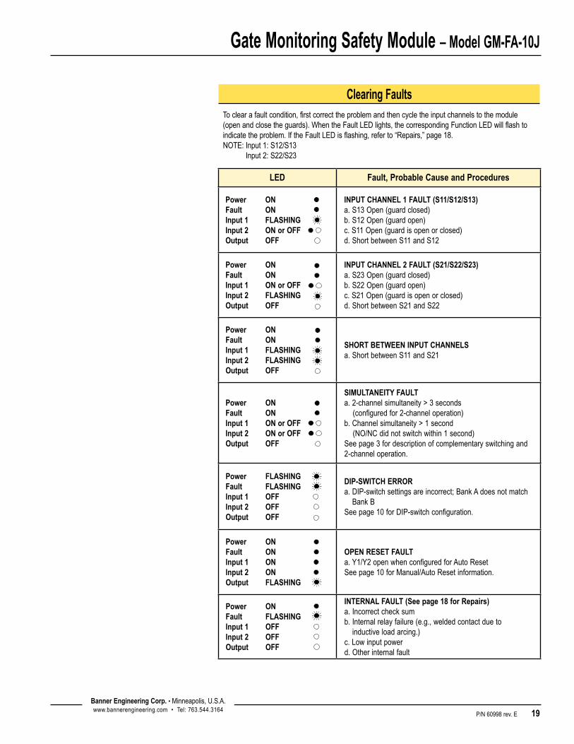
Clearing FaultsToclearafaultcondition,firstcorrecttheproblemandthencycletheinputchannelstothemodule(openandclosetheguards).WhentheFaultLEDlights,thecorrespondingFunctionLEDwillflashtoindicatetheproblem.IftheFaultLEDisflashing,referto“Repairs,”page18.NOTE:Input1:S12/S13
Input2:S22/S23
LED Fault, Probable Cause and Procedures
Power ONFault ON Input 1 FLASHING Input 2 ON or OFF Output OFF
INPUT CHANNEL 1 FAULT (S11/S12/S13) a.S13Open(guardclosed) b.S12Open(guardopen) c.S11Open(guardisopenorclosed) d.ShortbetweenS11andS12
Power ONFault ON Input 1 ON or OFF Input 2 FLASHING Output OFF
INPUT CHANNEL 2 FAULT (S21/S22/S23) a.S23Open(guardclosed) b.S22Open(guardopen) c.S21Open(guardisopenorclosed) d.ShortbetweenS21andS22
Power ONFault ON Input 1 FLASHING Input 2 FLASHING Output OFF
SHORT BETWEEN INPUT CHANNELS a.ShortbetweenS11andS21
Power ONFault ON Input 1 ON or OFF Input 2 ON or OFF Output OFF
SIMULTANEITY FAULT a.2-channelsimultaneity>3seconds(configuredfor2-channeloperation) b.Channelsimultaneity>1second (NO/NCdidnotswitchwithin1second)Seepage3fordescriptionofcomplementaryswitchingand2-channeloperation.
Power FLASHINGFault FLASHING Input 1 OFF Input 2 OFF Output OFF
DIP-SWITCH ERROR a.DIP-switchsettingsareincorrect;BankAdoesnotmatch
BankBSeepage10forDIP-switchconfiguration.
Power ONFault ON Input 1 ON Input 2 ON Output FLASHING
OPEN RESET FAULT a.Y1/Y2openwhenconfiguredforAutoResetSeepage10forManual/AutoResetinformation.
Power ONFault FLASHING Input 1 OFF Input 2 OFF Output OFF
INTERNAL FAULT (See page 18 for Repairs) a.Incorrectchecksum b.Internalrelayfailure(e.g.,weldedcontactdueto
inductiveloadarcing.)c.Lowinputpower d.Otherinternalfault

Gate Monitoring Safety Module – Model GM-FA-10J
WARRANTY: BannerEngineeringCorp.warrantsitsproductstobefreefromdefectsforoneyear.BannerEngineeringCorp.willrepairorreplace,freeofcharge,anyproductofitsmanufacturefoundtobedefectiveatthetimeitisreturnedtothefactoryduringthewarrantyperiod.ThiswarrantydoesnotcoverdamageorliabilityfortheimproperapplicationofBannerproducts.Thiswarrantyisinlieuofanyotherwarrantyeitherexpressedorimplied.
BannerEngineeringCorp.,9714TenthAve.No.,Minneapolis,MN55441•Phone:763.544.3164•www.bannerengineering.com•Email:[email protected]
P/N 60998 rev. E
For more information: Contact your local Banner representative or Banner Corporate Offices around the world.
Corporate Headquarters Europe Latin America
Banner Engineering Corp.
9714TenthAve.North Mpls.,MN55441 Tel:763-544-3164 www.bannerengineering.com [email protected]
Banner Engineering Europe
ParkLaneCulliganlaan2F DiegemB-1831 BELGIUM Tel:32-24560780 Fax:32-24560789 www.bannereurope.com [email protected]
Contact Banner Engineering Corp. (US) or e-mail
Mexico: [email protected]
Brazil: [email protected]
Asia — China Asia — Japan Asia India
Banner Engineering China
Shanghai Rep Office Rm.G/H/I,28thFlr. CrossRegionPlaza No.899,LinglingRoad Shanghai200030CHINA Tel:86-21-54894500 Fax:86-21-54894511 www.bannerengineering.com.cn [email protected]
Banner Engineering Japan
Cent-UrbanBuilding 3053-23-15Nishi-Nakajima Yodogawa-Ku, Osaka532-0011JAPAN Tel:81-6-6309-0411 Fax:81-6-6309-0416
www.bannerengineering.co.jp [email protected]
Banner Engineering Asia ─ Taiwan
NeihuTechnologyPark 5F-1,No.51,Lane35,JihuRd. Taipei114TAIWAN Tel:886-2-8751-9966 Fax:886-2-8751-2966 www.bannerengineering.com.tw [email protected]
Banner Engineering India
Pune Head Quarters Office No.1001SaiCapital,Opp. ICCSenapatiBapatRoad Pune411016INDIA Tel:91-20-66405624 Fax:91-20-66405623 www.bannerengineering.co.in [email protected]
BannerEngineeringCorp.,9714TenthAve.No.,Minneapolis,MN55441•Phone:763.544.3164•www.bannerengineering.com•Email:[email protected]
EC Declaration of ConformityBannerEngineringCorp.
9714TenthAvenueNorth
Minneapolis,MN55441-5019USA
WeherewithdeclarethatGM-FA-10JGateMonitoringSafetyModuleforindustrialcontrolisinconformitywiththeprovisionsoftheMachineryDirective(Directive98/37/EEC),andallessentialHealthandSafetyRequirementshavebeenmet.
10/16/2009
R.Eagle/EngineeringManager Date
DownloadthecompleteECDeclarationofConformityasaPDFfileatwww.bannerengineering.com/ESMODULE