Embed Size (px)
Citation preview

Dialogic® Global Call APIProgramming Guide
September 2008
05-1867-007

Dialogic® Global Call API Programming Guide – September 2008Dialogic Corporation
Copyright and Legal NoticeCopyright © 1996-2008 Dialogic Corporation. All Rights Reserved. You may not reproduce this document in whole or in part without permission in writing from Dialogic Corporation at the address provided below.
All contents of this document are furnished for informational use only and are subject to change without notice and do not represent a commitment on the part of Dialogic Corporation or its subsidiaries (“Dialogic”). Reasonable effort is made to ensure the accuracy of the information contained in the document. However, Dialogic does not warrant the accuracy of this information and cannot accept responsibility for errors, inaccuracies or omissions that may be contained in this document.
INFORMATION IN THIS DOCUMENT IS PROVIDED IN CONNECTION WITH DIALOGIC® PRODUCTS. NO LICENSE, EXPRESS OR IMPLIED, BY ESTOPPEL OR OTHERWISE, TO ANY INTELLECTUAL PROPERTY RIGHTS IS GRANTED BY THIS DOCUMENT. EXCEPT AS PROVIDED IN A SIGNED AGREEMENT BETWEEN YOU AND DIALOGIC, DIALOGIC ASSUMES NO LIABILITY WHATSOEVER, AND DIALOGIC DISCLAIMS ANY EXPRESS OR IMPLIED WARRANTY, RELATING TO SALE AND/OR USE OF DIALOGIC PRODUCTS INCLUDING LIABILITY OR WARRANTIES RELATING TO FITNESS FOR A PARTICULAR PURPOSE, MERCHANTABILITY, OR INFRINGEMENT OF ANY INTELLECTUAL PROPERTY RIGHT OF A THIRD PARTY.
Dialogic products are not intended for use in medical, life saving, life sustaining, critical control or safety systems, or in nuclear facility applications.
Due to differing national regulations and approval requirements, certain Dialogic products may be suitable for use only in specific countries, and thus may not function properly in other countries. You are responsible for ensuring that your use of such products occurs only in the countries where such use is suitable. For information on specific products, contact Dialogic Corporation at the address indicated below or on the web at www.dialogic.com.
It is possible that the use or implementation of any one of the concepts, applications, or ideas described in this document, in marketing collateral produced by or on web pages maintained by Dialogic may infringe one or more patents or other intellectual property rights owned by third parties. Dialogic does not provide any intellectual property licenses with the sale of Dialogic products other than a license to use such product in accordance with intellectual property owned or validly licensed by Dialogic and no such licenses are provided except pursuant to a signed agreement with Dialogic. More detailed information about such intellectual property is available from Dialogic’s legal department at 9800 Cavendish Blvd., 5th Floor, Montreal, Quebec, Canada H4M 2V9. Dialogic encourages all users of its products to procure all necessary intellectual property licenses required to implement any concepts or applications and does not condone or encourage any intellectual property infringement and disclaims any responsibility related thereto. These intellectual property licenses may differ from country to country and it is the responsibility of those who develop the concepts or applications to be aware of and comply with different national license requirements.
Dialogic, Dialogic Pro, Brooktrout, Cantata, SnowShore, Eicon, Eicon Networks, Eiconcard, Diva, SIPcontrol, Diva ISDN, TruFax, Realblocs, Realcomm 100, NetAccess, Instant ISDN, TRXStream, Exnet, Exnet Connect, EXS, ExchangePlus VSE, Switchkit, N20, Powering The Service-Ready Network, Vantage, Making Innovation Thrive, Connecting People to Information, Connecting to Growth and Shiva, among others as well as related logos, are either registered trademarks or trademarks of Dialogic. Dialogic's trademarks may be used publicly only with permission from Dialogic. Such permission may only be granted by Dialogic’s legal department at 9800 Cavendish Blvd., 5th Floor, Montreal, Quebec, Canada H4M 2V9. Any authorized use of Dialogic's trademarks will be subject to full respect of the trademark guidelines published by Dialogic from time to time and any use of Dialogic’s trademarks requires proper acknowledgement.
Microsoft, Visual C++, Windows, and Win32 are registered trademarks of Microsoft Corporation in the United States and/or other countries. The other names of actual companies and products mentioned herein are the trademarks of their respective owners.
Publication Date: September 2008
Document Number: 05-1867-007

Dialogic® Global Call API Programming Guide – September 2008 3Dialogic Corporation
Contents
Revision History . . . . . . . . . . . . . . . . . . . . . . . . . . . . . . . . . . . . . . . . . . . . . . . . . . . . . . . . . . . . . 11
About This Publication . . . . . . . . . . . . . . . . . . . . . . . . . . . . . . . . . . . . . . . . . . . . . . . . . . . . . . . 13
1 Product Description . . . . . . . . . . . . . . . . . . . . . . . . . . . . . . . . . . . . . . . . . . . . . . . . . . . . . . . . . . 17
1.1 Dialogic® Global Call API Software Overview . . . . . . . . . . . . . . . . . . . . . . . . . . . . . . . . . . 171.2 Dialogic® Global Call API Feature Categories. . . . . . . . . . . . . . . . . . . . . . . . . . . . . . . . . . 18
1.2.1 Call Control Features . . . . . . . . . . . . . . . . . . . . . . . . . . . . . . . . . . . . . . . . . . . . . . 181.2.2 Operation, Administration, and Maintenance Features. . . . . . . . . . . . . . . . . . . . . 19
1.3 Dialogic® Global Call API Architecture . . . . . . . . . . . . . . . . . . . . . . . . . . . . . . . . . . . . . . . 191.3.1 Overview. . . . . . . . . . . . . . . . . . . . . . . . . . . . . . . . . . . . . . . . . . . . . . . . . . . . . . . . 201.3.2 Dialogic® Global Call API . . . . . . . . . . . . . . . . . . . . . . . . . . . . . . . . . . . . . . . . . . . 20
1.4 Call Control Libraries . . . . . . . . . . . . . . . . . . . . . . . . . . . . . . . . . . . . . . . . . . . . . . . . . . . . . 211.4.1 Starting Call Control Libraries . . . . . . . . . . . . . . . . . . . . . . . . . . . . . . . . . . . . . . . . 221.4.2 Call Control Library States . . . . . . . . . . . . . . . . . . . . . . . . . . . . . . . . . . . . . . . . . . 22
1.5 Dialogic® Global Call API Object Identifiers. . . . . . . . . . . . . . . . . . . . . . . . . . . . . . . . . . . . 231.5.1 Line Device Identifier . . . . . . . . . . . . . . . . . . . . . . . . . . . . . . . . . . . . . . . . . . . . . . 241.5.2 Call Reference Number . . . . . . . . . . . . . . . . . . . . . . . . . . . . . . . . . . . . . . . . . . . . 241.5.3 Object Identifiers and Resource Sharing Across Processes . . . . . . . . . . . . . . . . 241.5.4 Target Objects . . . . . . . . . . . . . . . . . . . . . . . . . . . . . . . . . . . . . . . . . . . . . . . . . . . 25
1.6 Dialogic® Global Call API versus Dialogic® DTI API . . . . . . . . . . . . . . . . . . . . . . . . . . . . . 281.7 Dialogic® Global Call API versus Dialogic® ISDN API. . . . . . . . . . . . . . . . . . . . . . . . . . . . 29
2 Programming Models . . . . . . . . . . . . . . . . . . . . . . . . . . . . . . . . . . . . . . . . . . . . . . . . . . . . . . . . . 31
2.1 Programming Models Overview. . . . . . . . . . . . . . . . . . . . . . . . . . . . . . . . . . . . . . . . . . . . . 312.2 Synchronous Mode Programming for Linux . . . . . . . . . . . . . . . . . . . . . . . . . . . . . . . . . . . 312.3 Asynchronous Mode Programming for Linux. . . . . . . . . . . . . . . . . . . . . . . . . . . . . . . . . . . 312.4 Synchronous Mode Programming for Windows®. . . . . . . . . . . . . . . . . . . . . . . . . . . . . . . . . . . . . . . . 32
2.5 Asynchronous Mode Programming for Windows®. . . . . . . . . . . . . . . . . . . . . . . . . . . . . . . . . . . . . . . 33
2.5.1 Asynchronous Model Overview . . . . . . . . . . . . . . . . . . . . . . . . . . . . . . . . . . . . . . 342.5.2 Asynchronous Model with Event Handlers . . . . . . . . . . . . . . . . . . . . . . . . . . . . . . 352.5.3 Asynchronous with Windows® Callback Model . . . . . . . . . . . . . . . . . . . . . . . . . . 352.5.4 Asynchronous with Win32® Synchronization Model . . . . . . . . . . . . . . . . . . . . . . . 352.5.5 Extended Asynchronous Programming Model . . . . . . . . . . . . . . . . . . . . . . . . . . . 36
3 Call State Models . . . . . . . . . . . . . . . . . . . . . . . . . . . . . . . . . . . . . . . . . . . . . . . . . . . . . . . . . . . . 37
3.1 Call State Model Overview . . . . . . . . . . . . . . . . . . . . . . . . . . . . . . . . . . . . . . . . . . . . . . . . 373.2 Basic Call Model . . . . . . . . . . . . . . . . . . . . . . . . . . . . . . . . . . . . . . . . . . . . . . . . . . . . . . . . 37
3.2.1 Basic Call States at the Inbound Interface . . . . . . . . . . . . . . . . . . . . . . . . . . . . . . 383.2.2 Basic Call States at the Outbound Interface. . . . . . . . . . . . . . . . . . . . . . . . . . . . . 393.2.3 Basic Call States for Call Termination . . . . . . . . . . . . . . . . . . . . . . . . . . . . . . . . . 39
3.3 Basic Call Model Configuration Options . . . . . . . . . . . . . . . . . . . . . . . . . . . . . . . . . . . . . . 403.3.1 Call State Configuration . . . . . . . . . . . . . . . . . . . . . . . . . . . . . . . . . . . . . . . . . . . . 403.3.2 Call State Event Configuration . . . . . . . . . . . . . . . . . . . . . . . . . . . . . . . . . . . . . . . 413.3.3 Call Acknowledgment Configuration. . . . . . . . . . . . . . . . . . . . . . . . . . . . . . . . . . . 423.3.4 Call Proceeding Configuration . . . . . . . . . . . . . . . . . . . . . . . . . . . . . . . . . . . . . . . 42

4 Dialogic® Global Call API Programming Guide – September 2008Dialogic Corporation
Contents
3.3.5 Minimum Destination Information Configuration . . . . . . . . . . . . . . . . . . . . . . . . . . 433.3.6 Maximum Destination Information Configuration. . . . . . . . . . . . . . . . . . . . . . . . . . 43
3.4 Basic Call Control in Asynchronous Mode . . . . . . . . . . . . . . . . . . . . . . . . . . . . . . . . . . . . . 433.4.1 Inbound Calls in Asynchronous Mode . . . . . . . . . . . . . . . . . . . . . . . . . . . . . . . . . . 443.4.2 Outbound Calls in Asynchronous Mode . . . . . . . . . . . . . . . . . . . . . . . . . . . . . . . . 583.4.3 Call Termination in Asynchronous Mode . . . . . . . . . . . . . . . . . . . . . . . . . . . . . . . . 65
3.5 Basic Call Control in Synchronous Mode . . . . . . . . . . . . . . . . . . . . . . . . . . . . . . . . . . . . . . 693.5.1 Inbound Calls in Synchronous Mode . . . . . . . . . . . . . . . . . . . . . . . . . . . . . . . . . . . 693.5.2 Outbound Calls in Synchronous Mode . . . . . . . . . . . . . . . . . . . . . . . . . . . . . . . . . 793.5.3 Call Termination in Synchronous Mode. . . . . . . . . . . . . . . . . . . . . . . . . . . . . . . . . 833.5.4 Handling Unsolicited Events . . . . . . . . . . . . . . . . . . . . . . . . . . . . . . . . . . . . . . . . . 87
3.6 Advanced Call Control with Call Hold and Transfer . . . . . . . . . . . . . . . . . . . . . . . . . . . . . . 873.6.1 Advanced Call State Model Overview . . . . . . . . . . . . . . . . . . . . . . . . . . . . . . . . . . 873.6.2 Advanced Call States for Hold and Transfer . . . . . . . . . . . . . . . . . . . . . . . . . . . . . 883.6.3 Call Hold . . . . . . . . . . . . . . . . . . . . . . . . . . . . . . . . . . . . . . . . . . . . . . . . . . . . . . . . 883.6.4 Call Transfer . . . . . . . . . . . . . . . . . . . . . . . . . . . . . . . . . . . . . . . . . . . . . . . . . . . . . 89
4 Event Handling . . . . . . . . . . . . . . . . . . . . . . . . . . . . . . . . . . . . . . . . . . . . . . . . . . . . . . . . . . . . . . 95
4.1 Overview of Event Handling . . . . . . . . . . . . . . . . . . . . . . . . . . . . . . . . . . . . . . . . . . . . . . . . 954.2 Event Categories . . . . . . . . . . . . . . . . . . . . . . . . . . . . . . . . . . . . . . . . . . . . . . . . . . . . . . . . 954.3 Blocked and Unblocked Event Handling. . . . . . . . . . . . . . . . . . . . . . . . . . . . . . . . . . . . . . . 964.4 Event Retrieval . . . . . . . . . . . . . . . . . . . . . . . . . . . . . . . . . . . . . . . . . . . . . . . . . . . . . . . . . . 974.5 Events Indicating Errors . . . . . . . . . . . . . . . . . . . . . . . . . . . . . . . . . . . . . . . . . . . . . . . . . . . 984.6 Masking Events . . . . . . . . . . . . . . . . . . . . . . . . . . . . . . . . . . . . . . . . . . . . . . . . . . . . . . . . . 984.7 Event Handlers . . . . . . . . . . . . . . . . . . . . . . . . . . . . . . . . . . . . . . . . . . . . . . . . . . . . . . . . . . 98
4.7.1 Event Handlers for Linux . . . . . . . . . . . . . . . . . . . . . . . . . . . . . . . . . . . . . . . . . . . . 984.7.2 Event Handlers for Windows® . . . . . . . . . . . . . . . . . . . . . . . . . . . . . . . . . . . . . . . . . . . . . . . . . .99
5 Error Handling . . . . . . . . . . . . . . . . . . . . . . . . . . . . . . . . . . . . . . . . . . . . . . . . . . . . . . . . . . . . . . 101
5.1 Error Handling Overview. . . . . . . . . . . . . . . . . . . . . . . . . . . . . . . . . . . . . . . . . . . . . . . . . . 1015.2 Fatal Error Recovery. . . . . . . . . . . . . . . . . . . . . . . . . . . . . . . . . . . . . . . . . . . . . . . . . . . . . 102
6 Application Development Guidelines . . . . . . . . . . . . . . . . . . . . . . . . . . . . . . . . . . . . . . . . . . . 105
6.1 General Programming Tips. . . . . . . . . . . . . . . . . . . . . . . . . . . . . . . . . . . . . . . . . . . . . . . . 1056.2 Tips for Programming Drop and Insert Applications . . . . . . . . . . . . . . . . . . . . . . . . . . . . . 1066.3 Using Dialogic® Global Call API with Dialogic® DM3 Boards . . . . . . . . . . . . . . . . . . . . . . 108
6.3.1 Routing Configurations Overview . . . . . . . . . . . . . . . . . . . . . . . . . . . . . . . . . . . . 1086.3.2 Working with Flexible Routing Configurations . . . . . . . . . . . . . . . . . . . . . . . . . . . 1096.3.3 Working with Fixed Routing Configurations. . . . . . . . . . . . . . . . . . . . . . . . . . . . . 1156.3.4 Handling Multiple Call Objects Per Channel in a Glare Condition . . . . . . . . . . . . 1206.3.5 TDM Bus Time Slot Considerations. . . . . . . . . . . . . . . . . . . . . . . . . . . . . . . . . . . 121
7 Call Control . . . . . . . . . . . . . . . . . . . . . . . . . . . . . . . . . . . . . . . . . . . . . . . . . . . . . . . . . . . . . . . . 123
7.1 Call Analysis when Using Dialogic® Springware Boards . . . . . . . . . . . . . . . . . . . . . . . . . 1237.2 Call Progress Analysis when Using Dialogic® DM3 Boards . . . . . . . . . . . . . . . . . . . . . . . 124
7.2.1 Call Progress Analysis Definition. . . . . . . . . . . . . . . . . . . . . . . . . . . . . . . . . . . . . 1247.2.2 Configuring Default Call Progress Analysis Parameters . . . . . . . . . . . . . . . . . . . 1247.2.3 Configuring Call Progress Analysis on a Per Call Basis . . . . . . . . . . . . . . . . . . . 1257.2.4 Setting Call Analysis Attributes on a Per Call Basis . . . . . . . . . . . . . . . . . . . . . . 1277.2.5 Configuring Call Progress Analysis on a Per Channel Basis. . . . . . . . . . . . . . . . 1287.2.6 Setting Call Analysis Attributes on a Per Channel Basis . . . . . . . . . . . . . . . . . . . 129

Dialogic® Global Call API Programming Guide – September 2008 5Dialogic Corporation
Contents
7.2.7 Customizing Call Progress Tones on a Per Board Basis . . . . . . . . . . . . . . . . . . 1297.2.8 Customizing Nonstandard Special Information Tones . . . . . . . . . . . . . . . . . . . . 130
7.3 Resource Routing . . . . . . . . . . . . . . . . . . . . . . . . . . . . . . . . . . . . . . . . . . . . . . . . . . . . . . 1317.4 Feature Transparency and Extension . . . . . . . . . . . . . . . . . . . . . . . . . . . . . . . . . . . . . . . 132
7.4.1 Feature Transparency and Extension Overview. . . . . . . . . . . . . . . . . . . . . . . . . 1327.4.2 Technology-Specific Feature Access . . . . . . . . . . . . . . . . . . . . . . . . . . . . . . . . . 1327.4.3 Technology-Specific User Information . . . . . . . . . . . . . . . . . . . . . . . . . . . . . . . . 134
8 Alarm Handling . . . . . . . . . . . . . . . . . . . . . . . . . . . . . . . . . . . . . . . . . . . . . . . . . . . . . . . . . . . . . 135
8.1 Alarm Handling Overview . . . . . . . . . . . . . . . . . . . . . . . . . . . . . . . . . . . . . . . . . . . . . . . . 1358.1.1 Alarm Management System Components . . . . . . . . . . . . . . . . . . . . . . . . . . . . . 136
8.2 Operation and Configuration of GCAMS . . . . . . . . . . . . . . . . . . . . . . . . . . . . . . . . . . . . . 1378.2.1 Generation of Events for Blocking Alarms . . . . . . . . . . . . . . . . . . . . . . . . . . . . . 1378.2.2 Generation of Alarm Events . . . . . . . . . . . . . . . . . . . . . . . . . . . . . . . . . . . . . . . . 1388.2.3 Configuration of Alarm Properties and Characteristics . . . . . . . . . . . . . . . . . . . . 1398.2.4 Starting and Stopping Alarm Transmission. . . . . . . . . . . . . . . . . . . . . . . . . . . . . 1428.2.5 Retrieving Alarm Data. . . . . . . . . . . . . . . . . . . . . . . . . . . . . . . . . . . . . . . . . . . . . 142
8.3 Sample Alarm Scenarios . . . . . . . . . . . . . . . . . . . . . . . . . . . . . . . . . . . . . . . . . . . . . . . . . 1448.3.1 Scenario 1: Application Notified of First and Last Blocking Alarm . . . . . . . . . . . 1448.3.2 Scenario 2: Default Behavior for Alarm Notification . . . . . . . . . . . . . . . . . . . . . . 1468.3.3 Scenario 3: Alarm Transmission. . . . . . . . . . . . . . . . . . . . . . . . . . . . . . . . . . . . . 147
8.4 GCAMS and the DTI API Method of Alarm Handling . . . . . . . . . . . . . . . . . . . . . . . . . . . 147
9 Real Time Configuration Management . . . . . . . . . . . . . . . . . . . . . . . . . . . . . . . . . . . . . . . . . . 149
9.1 Real Time Configuration Management Overview . . . . . . . . . . . . . . . . . . . . . . . . . . . . . . 1499.2 RTCM Components . . . . . . . . . . . . . . . . . . . . . . . . . . . . . . . . . . . . . . . . . . . . . . . . . . . . . 150
9.2.1 Customer Application Using Dialogic® Global Call API RTCM. . . . . . . . . . . . . . 1519.2.2 Dialogic® Global Call RTCM. . . . . . . . . . . . . . . . . . . . . . . . . . . . . . . . . . . . . . . . 1519.2.3 RTCM Parameters . . . . . . . . . . . . . . . . . . . . . . . . . . . . . . . . . . . . . . . . . . . . . . . 152
9.3 Using RTCM Parameters. . . . . . . . . . . . . . . . . . . . . . . . . . . . . . . . . . . . . . . . . . . . . . . . . 1529.3.1 Parameter Dependencies . . . . . . . . . . . . . . . . . . . . . . . . . . . . . . . . . . . . . . . . . . 1539.3.2 Parameter Definitions . . . . . . . . . . . . . . . . . . . . . . . . . . . . . . . . . . . . . . . . . . . . . 153
9.4 Getting and Setting Parameter Information . . . . . . . . . . . . . . . . . . . . . . . . . . . . . . . . . . . 1549.4.1 GC_PARM_BLK Data Structure . . . . . . . . . . . . . . . . . . . . . . . . . . . . . . . . . . . . . 1549.4.2 Control Parameters. . . . . . . . . . . . . . . . . . . . . . . . . . . . . . . . . . . . . . . . . . . . . . . 155
9.5 Querying Configuration Data . . . . . . . . . . . . . . . . . . . . . . . . . . . . . . . . . . . . . . . . . . . . . . 1579.6 Handling RTCM Errors . . . . . . . . . . . . . . . . . . . . . . . . . . . . . . . . . . . . . . . . . . . . . . . . . . 1589.7 Configuration Procedure . . . . . . . . . . . . . . . . . . . . . . . . . . . . . . . . . . . . . . . . . . . . . . . . . 1589.8 Sample Scenarios Using the RTCM API Functions. . . . . . . . . . . . . . . . . . . . . . . . . . . . . 159
9.8.1 Getting or Setting GCLib Configuration in Synchronous Mode. . . . . . . . . . . . . . 1609.8.2 Getting or Setting CCLib Configuration in Synchronous Mode. . . . . . . . . . . . . . 1619.8.3 Getting or Setting Protocol Configuration in Synchronous Mode . . . . . . . . . . . . 1629.8.4 Getting or Setting Line Device Configuration in Synchronous Mode . . . . . . . . . 1649.8.5 Setting Line Device Configuration in Asynchronous Mode. . . . . . . . . . . . . . . . . 165
9.9 Dynamically Retrieving and Modifying Selected Protocol Parameters when Using Dialogic® DM3 Boards. . . . . . . . . . . . . . . . . . . . . . . . . . . . . . . . . . . . . . . . . . . . . . . . . . . . . . . . . . . 1679.9.1 Prerequisites for Feature Use. . . . . . . . . . . . . . . . . . . . . . . . . . . . . . . . . . . . . . . 1689.9.2 Retrieving a Protocol ID . . . . . . . . . . . . . . . . . . . . . . . . . . . . . . . . . . . . . . . . . . . 1699.9.3 Retrieving or Modifying CAS Signal Definitions . . . . . . . . . . . . . . . . . . . . . . . . . 1709.9.4 Retrieving or Modifying CDP Variable Values . . . . . . . . . . . . . . . . . . . . . . . . . . 172

6 Dialogic® Global Call API Programming Guide – September 2008Dialogic Corporation
Contents
9.9.5 Sample Code for Getting and Setting CAS Signal Definitions and CDP Variable Values . . . . . . . . . . . . . . . . . . . . . . . . . . . . . . . . . . . . . . . . . . . . . . . . . . . . . . . . . 173
9.9.6 Dynamically Configuring a Trunk. . . . . . . . . . . . . . . . . . . . . . . . . . . . . . . . . . . . . 1839.9.7 Applicable Data Structures, Set IDs, and Parm IDs . . . . . . . . . . . . . . . . . . . . . . 1879.9.8 Restrictions and Limitations. . . . . . . . . . . . . . . . . . . . . . . . . . . . . . . . . . . . . . . . . 189
10 Handling Service Requests . . . . . . . . . . . . . . . . . . . . . . . . . . . . . . . . . . . . . . . . . . . . . . . . . . . 191
10.1 Service Request Overview . . . . . . . . . . . . . . . . . . . . . . . . . . . . . . . . . . . . . . . . . . . . . . . . 19110.2 Service Request Components . . . . . . . . . . . . . . . . . . . . . . . . . . . . . . . . . . . . . . . . . . . . . 19210.3 Service Request Data. . . . . . . . . . . . . . . . . . . . . . . . . . . . . . . . . . . . . . . . . . . . . . . . . . . . 19310.4 General Service Request Scenario . . . . . . . . . . . . . . . . . . . . . . . . . . . . . . . . . . . . . . . . . 19310.5 ISDN BRI-Specific Service Request Scenario . . . . . . . . . . . . . . . . . . . . . . . . . . . . . . . . . 194
11 Using Dialogic® Global Call API to Implement Call Transfer . . . . . . . . . . . . . . . . . . . . . . . . 197
11.1 Introduction to Call Transfer . . . . . . . . . . . . . . . . . . . . . . . . . . . . . . . . . . . . . . . . . . . . . . . 19711.1.1 Blind Call Transfer . . . . . . . . . . . . . . . . . . . . . . . . . . . . . . . . . . . . . . . . . . . . . . . . 19711.1.2 Supervised Call Transfer . . . . . . . . . . . . . . . . . . . . . . . . . . . . . . . . . . . . . . . . . . . 198
11.2 Call Transfer State Machine . . . . . . . . . . . . . . . . . . . . . . . . . . . . . . . . . . . . . . . . . . . . . . . 198
12 Building Applications . . . . . . . . . . . . . . . . . . . . . . . . . . . . . . . . . . . . . . . . . . . . . . . . . . . . . . . . 205
12.1 Compiling and Linking in Linux . . . . . . . . . . . . . . . . . . . . . . . . . . . . . . . . . . . . . . . . . . . . . 20512.1.1 Include Files. . . . . . . . . . . . . . . . . . . . . . . . . . . . . . . . . . . . . . . . . . . . . . . . . . . . . 20512.1.2 Required Libraries . . . . . . . . . . . . . . . . . . . . . . . . . . . . . . . . . . . . . . . . . . . . . . . . 20512.1.3 Variables for Compiling and Linking Commands. . . . . . . . . . . . . . . . . . . . . . . . . 206
12.2 Compiling and Linking in Windows®. . . . . . . . . . . . . . . . . . . . . . . . . . . . . . . . . . . . . . . . . . . . . . . . . . . .206
12.2.1 Include Files. . . . . . . . . . . . . . . . . . . . . . . . . . . . . . . . . . . . . . . . . . . . . . . . . . . . . 20612.2.2 Required Libraries . . . . . . . . . . . . . . . . . . . . . . . . . . . . . . . . . . . . . . . . . . . . . . . . 20712.2.3 Variables for Compiling and Linking Commands. . . . . . . . . . . . . . . . . . . . . . . . . 20712.2.4 Dynamically Loaded Libraries . . . . . . . . . . . . . . . . . . . . . . . . . . . . . . . . . . . . . . . 20712.2.5 Dynamically Loaded Protocol Modules . . . . . . . . . . . . . . . . . . . . . . . . . . . . . . . . 208
13 Debugging . . . . . . . . . . . . . . . . . . . . . . . . . . . . . . . . . . . . . . . . . . . . . . . . . . . . . . . . . . . . . . . . . 209
Glossary . . . . . . . . . . . . . . . . . . . . . . . . . . . . . . . . . . . . . . . . . . . . . . . . . . . . . . . . . . . . . . . . . . . 211
Index . . . . . . . . . . . . . . . . . . . . . . . . . . . . . . . . . . . . . . . . . . . . . . . . . . . . . . . . . . . . . . . . . . . . . . 219
Dialogic® Global Call API Programming Guide – September 2008 7Dialogic Corporation
Contents
Figures
1 Dialogic® Global Call API Architecture . . . . . . . . . . . . . . . . . . . . . . . . . . . . . . . . . . . . . . . . . . . 202 Call Control Library States. . . . . . . . . . . . . . . . . . . . . . . . . . . . . . . . . . . . . . . . . . . . . . . . . . . . . 223 Basic Asynchronous Inbound Call State Diagram. . . . . . . . . . . . . . . . . . . . . . . . . . . . . . . . . . . 454 Basic Asynchronous Inbound Call Scenario . . . . . . . . . . . . . . . . . . . . . . . . . . . . . . . . . . . . . . . 535 Incoming Call Scenario with Call Proceeding . . . . . . . . . . . . . . . . . . . . . . . . . . . . . . . . . . . . . . 546 Call Acknowledgment and Call Proceeding Done at the Application Layer. . . . . . . . . . . . . . . . 557 Call Proceeding Done by the Application Layer with Minimum Information Configured . . . . . . 568 Call Acknowledgment and Call Proceeding Done at Technology Call Control Layer . . . . . . . . 579 Call Acknowledgment Done by the Technology Call Control Layer and Call Proceeding Done by
the Application . . . . . . . . . . . . . . . . . . . . . . . . . . . . . . . . . . . . . . . . . . . . . . . . . . . . . . . . . . . . . . 5810 Basic Asynchronous Outbound Call State Diagram . . . . . . . . . . . . . . . . . . . . . . . . . . . . . . . . . 6011 Asynchronous Outbound Call Scenario. . . . . . . . . . . . . . . . . . . . . . . . . . . . . . . . . . . . . . . . . . . 6412 Asynchronous Outbound Call Scenario with Call Acknowledgment . . . . . . . . . . . . . . . . . . . . . 6413 Asynchronous Outbound Call Scenario with Overlap Sending . . . . . . . . . . . . . . . . . . . . . . . . . 6514 Asynchronous Call Tear-Down State Diagram . . . . . . . . . . . . . . . . . . . . . . . . . . . . . . . . . . . . . 6615 User Initiated Asynchronous Call Termination Scenario . . . . . . . . . . . . . . . . . . . . . . . . . . . . . . 6816 Network Initiated Asynchronous Call Termination Scenario . . . . . . . . . . . . . . . . . . . . . . . . . . . 6817 Basic Synchronous Inbound Call State Diagram. . . . . . . . . . . . . . . . . . . . . . . . . . . . . . . . . . . . 7018 Synchronous Inbound Call Scenario . . . . . . . . . . . . . . . . . . . . . . . . . . . . . . . . . . . . . . . . . . . . . 7719 Synchronous Inbound Call Scenario with Call Acknowledgment . . . . . . . . . . . . . . . . . . . . . . . 7820 Synchronous Inbound Call Scenario with Overlap Receiving . . . . . . . . . . . . . . . . . . . . . . . . . . 7921 Outbound Synchronous Call Process . . . . . . . . . . . . . . . . . . . . . . . . . . . . . . . . . . . . . . . . . . . . 8022 Outbound Call Scenario in Synchronous Mode. . . . . . . . . . . . . . . . . . . . . . . . . . . . . . . . . . . . . 8223 Synchronous Call Tear-Down State Diagram . . . . . . . . . . . . . . . . . . . . . . . . . . . . . . . . . . . . . . 8424 User Initiated Call Termination Scenario in Synchronous Mode . . . . . . . . . . . . . . . . . . . . . . . . 8625 Network Initiated Synchronous Call Termination Scenario . . . . . . . . . . . . . . . . . . . . . . . . . . . . 8626 Call State Transitions for Hold and Retrieve . . . . . . . . . . . . . . . . . . . . . . . . . . . . . . . . . . . . . . . 8927 Call State Model for Supervised and Unsupervised Transfers . . . . . . . . . . . . . . . . . . . . . . . . . 9128 Call Termination by the Network or Application During a Transfer . . . . . . . . . . . . . . . . . . . . . . 9229 Cluster Configurations for Fixed and Flexible Routing . . . . . . . . . . . . . . . . . . . . . . . . . . . . . . 10930 Architectural Diagram of Alarm Management Components . . . . . . . . . . . . . . . . . . . . . . . . . . 13631 Notification of First and Last Blocking Alarm . . . . . . . . . . . . . . . . . . . . . . . . . . . . . . . . . . . . . . 14532 Default Behavior for Alarm Notification . . . . . . . . . . . . . . . . . . . . . . . . . . . . . . . . . . . . . . . . . . 14633 Alarm Transmission . . . . . . . . . . . . . . . . . . . . . . . . . . . . . . . . . . . . . . . . . . . . . . . . . . . . . . . . . 14734 Relationship of Customer Application, Dialogic® Global Call RTCM, and RTCM Parameters 15035 Run Time Configuration Procedure . . . . . . . . . . . . . . . . . . . . . . . . . . . . . . . . . . . . . . . . . . . . . 15936 Getting or Setting GCLib Configuration in Synchronous Mode . . . . . . . . . . . . . . . . . . . . . . . . 16037 Getting or Setting CCLib Configuration in Synchronous Mode . . . . . . . . . . . . . . . . . . . . . . . . 16138 Getting or Setting Protocol Configuration in Synchronous Mode . . . . . . . . . . . . . . . . . . . . . . 16239 Getting or Setting Line Device Configuration in Synchronous Mode. . . . . . . . . . . . . . . . . . . . 16440 Setting Line Device Configuration in Asynchronous Mode . . . . . . . . . . . . . . . . . . . . . . . . . . . 16641 Service Request Architecture . . . . . . . . . . . . . . . . . . . . . . . . . . . . . . . . . . . . . . . . . . . . . . . . . 192

8 Dialogic® Global Call API Programming Guide – September 2008Dialogic Corporation
Contents
42 Generic Service Request Operation. . . . . . . . . . . . . . . . . . . . . . . . . . . . . . . . . . . . . . . . . . . . . 19443 ISDN BRI Service Request Operation . . . . . . . . . . . . . . . . . . . . . . . . . . . . . . . . . . . . . . . . . . . 19544 Blind Call Transfer (Unsupervised Transfer) . . . . . . . . . . . . . . . . . . . . . . . . . . . . . . . . . . . . . . 19845 Supervised Call Transfer . . . . . . . . . . . . . . . . . . . . . . . . . . . . . . . . . . . . . . . . . . . . . . . . . . . . . 19846 Call State Model for Blind Call Transfer at Party A. . . . . . . . . . . . . . . . . . . . . . . . . . . . . . . . . . 20047 Call State Model for Blind Call Transfer at Party B. . . . . . . . . . . . . . . . . . . . . . . . . . . . . . . . . . 20148 Call State Model for Supervised Transfer at Party A . . . . . . . . . . . . . . . . . . . . . . . . . . . . . . . . 20249 Call State Model for Supervised Transfer at Party B . . . . . . . . . . . . . . . . . . . . . . . . . . . . . . . . 20350 Call State Model for Supervised Transfer at Party C . . . . . . . . . . . . . . . . . . . . . . . . . . . . . . . . 204

Dialogic® Global Call API Programming Guide – September 2008 9Dialogic Corporation
Contents
Tables
1 Call Control Library States. . . . . . . . . . . . . . . . . . . . . . . . . . . . . . . . . . . . . . . . . . . . . . . . . . . . . 222 Supported Target Types . . . . . . . . . . . . . . . . . . . . . . . . . . . . . . . . . . . . . . . . . . . . . . . . . . . . . . 253 Target Types and Target IDs. . . . . . . . . . . . . . . . . . . . . . . . . . . . . . . . . . . . . . . . . . . . . . . . . . . 264 Target Object Availability . . . . . . . . . . . . . . . . . . . . . . . . . . . . . . . . . . . . . . . . . . . . . . . . . . . . . . 275 Obtaining Target IDs . . . . . . . . . . . . . . . . . . . . . . . . . . . . . . . . . . . . . . . . . . . . . . . . . . . . . . . . . 276 Asynchronous Inbound Call State Transitions. . . . . . . . . . . . . . . . . . . . . . . . . . . . . . . . . . . . . . 467 Asynchronous Outbound Call State Transitions . . . . . . . . . . . . . . . . . . . . . . . . . . . . . . . . . . . . 618 Asynchronous Call Termination Call State Transitions . . . . . . . . . . . . . . . . . . . . . . . . . . . . . . . 679 Synchronous Inbound Call State Transitions. . . . . . . . . . . . . . . . . . . . . . . . . . . . . . . . . . . . . . . 7110 Synchronous Outbound Call State Transitions . . . . . . . . . . . . . . . . . . . . . . . . . . . . . . . . . . . . . 8111 Synchronous Call Termination Call State Transitions . . . . . . . . . . . . . . . . . . . . . . . . . . . . . . . . 8512 Unsolicited Events Requiring Signal Handlers . . . . . . . . . . . . . . . . . . . . . . . . . . . . . . . . . . . . . 8713 Dialogic® Global Call Function Restrictions in a Fixed Routing Configuration . . . . . . . . . . . . 11614 Handling Glare. . . . . . . . . . . . . . . . . . . . . . . . . . . . . . . . . . . . . . . . . . . . . . . . . . . . . . . . . . . . . 12015 Call Progress Analysis Settings and Possible Results . . . . . . . . . . . . . . . . . . . . . . . . . . . . . . 12616 Comparison with Call Progress Analysis Using gc_SetParm( ). . . . . . . . . . . . . . . . . . . . . . . . 12917 Update Condition Flag and Dialogic® Global Call Process . . . . . . . . . . . . . . . . . . . . . . . . . . . 15718 Dialogic® Global Call API Call Transfer States . . . . . . . . . . . . . . . . . . . . . . . . . . . . . . . . . . . . 199

10 Dialogic® Global Call API Programming Guide – September 2008Dialogic Corporation
Contents

Dialogic® Global Call API Programming Guide — September 2008 11
Dialogic Corporation
Revision History
This revision history summarizes the changes made in each published version of this document.
Document No. Publication Date Description of Revisions
05-1867-007 September 2008 Made global changes to reflect Dialogic brand and changed title to “Dialogic® Global Call API Programming Guide.”
Merged Linux information into this Programming Guide so that this version supports both the Linux and Windows® operating systems and supersedes the Linux-only version, document number 05-1817-003.
Call Control section: Added Customizing Nonstandard Special Information Tones.
Real Time Configuration Management section: Added Dynamically Retrieving and Modifying Selected Protocol Parameters when Using Dialogic® DM3 Boards.
05-1867-006 May 2006 Call Control Libraries section: Updated the library descriptions to identify the technologies/protocols that each library supports.
Setting Call Analysis Attributes on a Per Call Basis section: Updated descriptions of the CCPARM_CA_PAMD_QTEMP and CCPARM_CA_PVD_QTEMP parameter IDs. Replaced the note that describes PAMD/PVD qualification template defaults and references the technote for tuning these parameters.
Using Protocols with Dialogic® DM3 Boards (Flexible Routing) section: Fixed incorrect references to using the Dialogic® DM3 PDK Manager and the FCDGEN utility.
Debugging chapter : Added reference to the “Runtime Trace Facility (RTF) Reference” chapter in the Dialogic® System Software Diagnostics Guide.
05-1867-005 September 2005 Starting Call Control Libraries section: Added note about loading only the required call control libraries to keep the required memory footprint small.
Synchronous Mode Programming section: Added restriction that no more than one synchronous function can be called on the same device simultaneously from different threads.
Overlap Sending section: Explicitly mentioned ISDN in the list of technologies that do not have messages to request more information.
Working with Flexible Routing Configurations section: Added note to check Release Guide for a system release to determine the routing configuration supported by a board.
Using Protocols with Dialogic® DM3 Boards (Flexible Routing) section: Updated to indicate protocols available with system release software or on a separate CD.
Country Dependent Parameter (CDP) Files section: Updated to indicate protocols available with system release software or on a separate CD.
Supervised Transfers section: Updated the call termination figure and added note to describe the unsolicited GCEV_CONNECTED event that is generated for a call when the new call being set up is terminated.
Working with Fixed Routing Configurations section: Added note to check Release Guide for a system release to determine the routing configuration supported by a board.
Call Transfer Overview section: Added note to clarify that the generic method of call transfer described is not supported by all technologies.

12 Dialogic® Global Call API Programming Guide — September 2008Dialogic Corporation
Revision History
05-1867-005 (continued)
TDM Bus Time Slot Considerations section: Added to describe when the sharing of time slots (SOT) algorithm applies.
Real Time Configuration Management chapter : Fixed several references to gc_util_insert_val( ) and gc_util_insert_ref( ) which should be gc_util_insert_parm_val( ) and gc_util_insert_parm_ref( ).
05-1867-004 September 2004 Supervised Transfers and Unsupervised Transfers sections: Changed the captions and the order of the two figures describing the call state transitions. (PTR 32481)
Event Retrieval section: Added text to explain that the memory pointed by the extevtdatap field in the METAEVENT structure is read-only.
GCAMS and the DTI API Method of Alarm Handling section: Added to describe workaround to continue using DTI API for alarm handling if absolutely necessary.
05-1867-003 November 2003 General: Removed all references to ANAPI.
Application Development Guidelines chapter : Removed the Programming Tip When Using a DI/0408-LS-A Board section that provided inaccurate information. (PTR 31145)
Configuring Default Call Progress Analysis Parameters section: Added section to point to the appropriate Global Call Technology Guide for information if default CPA parameter configuration (in the CONFIG file) is supported by the technology.
Building Applications chapter : Deleted a section on cross-compiler compatibility, which contained a reference to using the Borland compiler which is not supported.
05-1867-002 September 2003 Call Progress Analysis when Using Dialogic® DM3 Boards section: Added to describe a new unified method of implementing call progress analysis (CPA) when using Analog, E1/T1, and ISDN protocols on Dialogic® DM3 Boards.
05-1867-001 November 2002 Initial version of document. Much of the information contained in this document was previously published in the Dialogic® GlobalCall Application Developer’s Guide for UNIX and Windows®, document number 05-1526-002, and the Dialogic® GlobalCall API Software Reference for Linux and Windows®, document number 05-0387-009.
Document No. Publication Date Description of Revisions

Dialogic® Global Call API Programming Guide — September 2008 13
Dialogic Corporation
About This Publication
The following topics provide information about this publication:
• Purpose
• Applicability
• Intended Audience
• How to Use This Publication
• Related Information
Purpose
This publication provides guidelines for those choosing to use the Dialogic® Global Call API to build computer telephony applications that require call control functionality. Such applications include, but are not limited to, call routing, enhanced services, unified messaging, voice messaging, LAN telephony services, computer telephony services, switching, PBX, interactive voice response, help desk, and work flow applications.
This publication is a companion guide to the Dialogic® Global Call API Library Reference, which provides details on the functions, parameters, and data structures in the Global Call library, and the Dialogic® Global Call Technology Guides, which provide analog-, E1/T1-, IP-, ISDN-, and SS7-specific information.
Applicability
This document version (05-1867-007) is published for Dialogic® System Release Software for Linux and Windows® operating systems.
This document may also be applicable to other software releases (including service updates) on Linux or Windows® operating systems. Check the Release Guide for your software release to determine whether this document is supported.
Intended Audience
This publication is written for the following audience:
• Distributors
• System Integrators
• Toolkit Developers
• Independent Software Vendors (ISVs)

14 Dialogic® Global Call API Programming Guide — September 2008Dialogic Corporation
About This Publication
• Value Added Resellers (VARs)
• Original Equipment Manufacturers (OEMs)
How to Use This Publication
Refer to this publication after you have installed the hardware and the Dialogic® System Release Software, which includes the Dialogic® Global Call software.
This publication assumes that you are familiar with the operating system you are using (Linux or Windows®) and the C programming language.
The information in this guide is organized as follows:
• Chapter 1, “Product Description” provides an overview of the Global Call development software.
• Chapter 2, “Programming Models” describes the supported programming models in the Linux and Windows® environments.
• Chapter 3, “Call State Models” describes the call state models used by Global Call.
• Chapter 4, “Event Handling” describes how to handle Global Call events.
• Chapter 5, “Error Handling” describes the error handling facilities provided by Global Call.
• Chapter 6, “Application Development Guidelines” provides guidelines for developing applications that use Global Call.
• Chapter 7, “Call Control” describes basic call control capabilities, resource routing, and feature extensions provided by Global Call.
• Chapter 8, “Alarm Handling” describes how Global Call can be used to handle alarms.
• Chapter 9, “Real Time Configuration Management” describes how Global Call can be used for real time configuration of parameters associated with the interface.
• Chapter 10, “Handling Service Requests” describes the generic service request facility provided by Global Call.
• Chapter 11, “Using Dialogic® Global Call API to Implement Call Transfer” provides general information on the implementation of unsupervised (blind) and supervised call transfer.
• Chapter 12, “Building Applications” provides guidelines for those choosing to build applications that use Global Call software.
• Chapter 13, “Debugging” provides pointers to where technology-specific debugging information can be obtained.
• The Glossary provides a definition of terms used in this guide.
Related Information
See the following for additional information:
• http://www.dialogic.com/manuals/ (for Dialogic® product documentation)
• http://www.dialogic.com/support/ (for Dialogic technical support)

Dialogic® Global Call API Programming Guide — September 2008 15
Dialogic Corporation
About This Publication
• http://www.dialogic.com/ (for Dialogic® product information)

16 Dialogic® Global Call API Programming Guide — September 2008Dialogic Corporation
About This Publication

Dialogic® Global Call API Programming Guide — September 2008 17Dialogic Corporation
11.Product Description
This chapter describes the Dialogic® Global Call API software. Topics include:
• Dialogic® Global Call API Software Overview . . . . . . . . . . . . . . . . . . . . . . . . . . . . . . 17
• Dialogic® Global Call API Feature Categories . . . . . . . . . . . . . . . . . . . . . . . . . . . . . . . 18
• Dialogic® Global Call API Architecture . . . . . . . . . . . . . . . . . . . . . . . . . . . . . . . . . . . . 19
• Call Control Libraries . . . . . . . . . . . . . . . . . . . . . . . . . . . . . . . . . . . . . . . . . . . . . . . . . . 21
• Dialogic® Global Call API Object Identifiers . . . . . . . . . . . . . . . . . . . . . . . . . . . . . . . . 23
• Dialogic® Global Call API versus Dialogic® DTI API. . . . . . . . . . . . . . . . . . . . . . . . . 28
• Dialogic® Global Call API versus Dialogic® ISDN API . . . . . . . . . . . . . . . . . . . . . . . 29
1.1 Dialogic® Global Call API Software Overview
Dialogic® Global Call API software provides a common signaling interface for network-enabled applications, regardless of the signaling protocol needed to connect to the local telephone network. The signaling interface provided by Global Call software facilitates the exchange of call control messages between the telephone network and any network-enabled applications. Global Call software enables developers to create applications that can work with signaling systems worldwide, regardless of the network to which the applications are connected. The Global Call software is well suited for high-density, network-enabled solutions, such as voice, data, and video applications, where the supported hardware and signaling technology can vary widely from country to country.
As an example, the signal acknowledgment or information flow required to establish a call may vary from country to country. Rather than requiring the application to handle low-level details, Global Call offers a consistent, high-level interface to the user and handles each country's unique protocol requirements transparently to the application.
The Global Call software comprises three major components:
Global Call Application Programming Interface (API) A common, extensible API providing network interfaces to higher levels of software. Application developers use API function calls in their computer telephony applications.
Call Control Libraries A set of libraries that provide the interface between Global Call and the various network signaling protocols.
Global Call Protocols Network signaling protocols, such as T1 Robbed Bit, E1 CAS, ISDN, Analog, QSIG, SS7, and IP H.323 and SIP can be invoked by Global Call to facilitate call control.
18 Dialogic® Global Call API Programming Guide — September 2008Dialogic Corporation
Product Description
1.2 Dialogic® Global Call API Feature Categories
The Dialogic® Global Call API provides many features allowing for the development of flexible and robust applications. The features fall into one of two main categories:
• Call Control Features
• Operation, Administration, and Maintenance Features
1.2.1 Call Control Features
Global Call software provides the following call control features:
Basic call control Includes basic call control features such as the ability to make a call, detect a call, answer a call, release a call, etc. The implementation of these capabilities is based on the basic call state model, which is a common model for all network technologies. The procedures for establishing and terminating calls differ for the asynchronous and synchronous call models, and are therefore discussed in separate sections of this document. See Section 3.2, “Basic Call Model” for more information on the basic call model.
Advanced call model Defines the behavior for advanced features, such as hold and transfer. These capabilities are provided to support technologies and protocols that support such features, for example, supervised transfer. The implementation of these capabilities is based on a more advanced call state model. See Section 3.6, “Advanced Call Control with Call Hold and Transfer” for more information.
Call progress and call analysis Provides the capabilities for handling pre-connect (call progress) information that reports the status of the call connection, such as busy, no dial tone, or no ringback, and post connect (call analysis) information that reports the destination party’s media type, for example, voice, answering machine, or fax modem. This information is determined by the detection of tones defined specifically for this purpose. See Section 7.1, “Call Analysis when Using Dialogic® Springware Boards” and Section 7.2, “Call Progress Analysis when Using Dialogic® DM3 Boards” for more information.
Feature transparency and extension (FTE) Provides the ability to extend the capabilities of the Global Call software to handle features that are specific to a particular technology so that those features are accessible via the Global Call interface. For example, for ISDN applications, Global Call supports supplementary services such as overlap send, overlap receive, any message, any IE, and user-to-user messaging. See Section 7.4, “Feature Transparency and Extension” for more information.

Dialogic® Global Call API Programming Guide — September 2008 19Dialogic Corporation
Product Description
1.2.2 Operation, Administration, and Maintenance Features
Global Call software provides the following features that facilitate the operation, administration, and maintenance of Global Call applications:
Error handling functionality When an error occurs, the Global Call API provides functions that enable an application to retrieve more information about the error. See Chapter 5, “Error Handling” for more information.
Event handling functionality Provides the ability to handle and process events, including the ability to disable and enable events and to retrieve event information. See Chapter 4, “Event Handling” for more information.
Global Call Alarm Management System (GCAMS) Provides the ability to manage alarms. GCAMS provides Global Call applications with the ability to receive extensive alarm information that can be used in conjunction with information from the Central Office (CO) to troubleshoot line problems. See Chapter 8, “Alarm Handling” for more information.
Real Time Configuration Management (RTCM) Allows the modification of call control and protocol elements in real time, providing a single common user interface for configuration management. See Chapter 9, “Real Time Configuration Management” for more information.
Global Call Service Request (GCSR) Enables an application to send a request for a service to a remote device. Examples of the types of services that this feature supports are device registration, channel setup, call setup, information requests, or other kinds of requests that need to be made between two devices across the network. See Chapter 10, “Handling Service Requests” for more information.
Library information functions Enables an application to get information about the call control libraries being used. See the Dialogic® Global Call API Library Reference for more information about these functions.
Debugging facilities The Global Call API provides powerful debugging capabilities for troubleshooting protocol-related problems, including the ability to generate a detailed log file. See the appropriate Dialogic® Global Call Technology Guide for information on the debugging facilities available when using the Global Call API with each technology.
1.3 Dialogic® Global Call API Architecture
The Dialogic® Global Call API development software architecture is based on the Dialogic® architecture that supports Dialogic® Springware and Dialogic® DM3 Boards. The architecture is described in the following topics:
• Overview
• Dialogic® Global Call API
20 Dialogic® Global Call API Programming Guide — September 2008Dialogic Corporation
Product Description
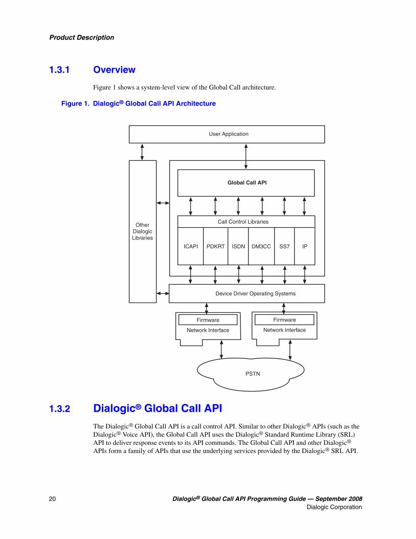
1.3.1 Overview
Figure 1 shows a system-level view of the Global Call architecture.
Figure 1. Dialogic® Global Call API Architecture
1.3.2 Dialogic® Global Call API
The Dialogic® Global Call API is a call control API. Similar to other Dialogic® APIs (such as the Dialogic® Voice API), the Global Call API uses the Dialogic® Standard Runtime Library (SRL) API to deliver response events to its API commands. The Global Call API and other Dialogic® APIs form a family of APIs that use the underlying services provided by the Dialogic® SRL API.
User Application
OtherDialogicLibraries
Global Call API
Call Control Libraries
ICAPI PDKRT ISDN DM3CC SS7 IP
Device Driver Operating Systems
Firmware
Network Interface
Firmware
Network Interface
PSTN

Dialogic® Global Call API Programming Guide — September 2008 21Dialogic Corporation
Product Description
The Global Call API provides a collection of functions supporting call control operations as well as functions to support operation, administration, and maintenance tasks. See the Dialogic® Global Call API Library Reference for detailed information about each function.
1.4 Call Control Libraries
Each supported network technology requires a call control library to provide the interface between the network and the Dialogic® Global Call API library. The call control libraries currently supported by Global Call are as follows:
GC_CUSTOM1_LIB The first of two call control library place holders for custom call control libraries. Any third-party Global Call compatible call control library can be used as a custom library. The Global Call library supports up to two custom libraries.
GC_CUSTOM2_LIB The second of two call control library place holders for custom call control libraries. Any third-party Global Call compatible call control library can be used as a custom library. The Global Call library supports up to two custom libraries.
GC_DM3CC_LIB The call control library that controls access to network interfaces on Dialogic® DM3 Boards. This library is used for call control using ISDN and CAS/R2MF (PDK protocols) signaling on Dialogic® DM3 Boards.
GC_H3R_LIBThe call control library that controls access to IP network interfaces. This call control library supports IP H.323 and SIP protocols and is used in conjunction with GC_IPM_LIB.
GC_ICAPI_LIB The Interface Control Application Programming Interface (ICAPI) call control library that controls access to network interfaces that use T1 robbed bit signaling or E1 CAS and ICAPI protocols. This library is used for call control using CAS/R2MF (ICAPI protocols) signaling on Dialogic® Springware Boards only.
GC_IPM_LIB The call control library that provides access to IP media resources. This library is used for H.323/SIP call control signaling and is used in conjunction with GC_H3R_LIB.
GC_ISDN_LIB The Integrated Services Digital Network (ISDN) call control library that controls network interfaces connected to an ISDN network. This library is used for ISDN call control signaling on Dialogic® Springware Boards only.
GC_PDKRT_LIB The Protocol Development Kit Run Time (PDKRT) call control library that controls access to network interfaces that use T1 robbed bit signaling or E1 CAS and PDK protocols. The PDKRT is a flexible engine and can be used to add features to protocols. This library is used for call control using CAS/R2MF (PDK protocols) signaling on Dialogic® Springware Boards only.
22 Dialogic® Global Call API Programming Guide — September 2008Dialogic Corporation
Product Description
GC_SS7_LIB The call control library that controls SS7 network interfaces on Dialogic® SS7 Boards. This library is used for SS7 call control signaling only.
1.4.1 Starting Call Control Libraries
Call control libraries must be started before they can be used by Global Call functions. The call control libraries are started when a gc_Start( ) function is issued. The gc_Start( ) function allows the selective starting of call control libraries where the application can specify if all the call control libraries are to be started or only specified libraries are to be started. The application can also start a custom call control library that is not supported by Global Call. See the Dialogic® Global Call API Library Reference for more information about the gc_Start( ) function.
Note: Invoking gc_Start(NULL) loads all call control libraries and consequently the memory footprint includes memory that is allocated for all call control libraries. To reduce the memory footprint, selective loading of call control libraries should be done. For example, if only the ISDN and PDKRT call control libraries are required, load GC_ISDN_LIB and GC_PDKRT_LIB only. For more information and an example, see the gc_Start( ) function in the Dialogic® Global Call API Library Reference.
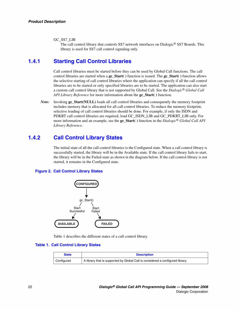
1.4.2 Call Control Library States
The initial state of all the call control libraries is the Configured state. When a call control library is successfully started, the library will be in the Available state. If the call control library fails to start, the library will be in the Failed state as shown in the diagram below. If the call control library is not started, it remains in the Configured state.
Figure 2. Call Control Library States
Table 1 describes the different states of a call control library.
gc_Start()
StartFailed
StartSuccessful
CONFIGURED
AVAILABLE FAILED
Table 1. Call Control Library States
State Description
Configured A library that is supported by Global Call is considered a configured library.

Dialogic® Global Call API Programming Guide — September 2008 23Dialogic Corporation
Product Description
Each configured call control library is assigned an ID number by Global Call. Each library also has a name in an ASCII string format. Library functions perform tasks such as converting a call control library ID to an ASCII name and vice-versa, determining the configured libraries, determining the available libraries, determining the libraries that started and the libraries that failed to start, and other library functions.
The following functions are the call control library information functions. All the library functions are synchronous, thus they return without a termination event.
• gc_CCLibIDToName( )
• gc_CCLibNameToID( )
• gc_CCLibStatusEx( )
• gc_GetVer( )
See the Dialogic® Global Call API Library Reference for detailed information about these functions.
1.5 Dialogic® Global Call API Object Identifiers
The Dialogic® Global Call API is call-oriented, that is, each call initiated by the application or network is assigned a call reference number (CRN) for call control and tracking purposes. Call handling is independent of the line device over which the call is routed. Each line device or device group is assigned a line device identifier (LDID) that enables the application to address any resource or group of resources using a single device identifier. Certain features, such as Feature Transparency and Extension (FTE), Real Time Configuration Management (RTCM), and Global Call Service Request (GCSR) operate on a basic entity called a Global Call target object. Target objects are identified by a target type and a target ID.
The following topics provide more detailed information:
• Line Device Identifier
• Call Reference Number
• Object Identifiers and Resource Sharing Across Processes
• Target Objects
Available A library that has been successfully started is considered to be available for use by a Global Call application.
Failed A library that has failed to start is considered to be unavailable for use by a Global Call application.
Table 1. Call Control Library States (Continued)
State Description

24 Dialogic® Global Call API Programming Guide — September 2008Dialogic Corporation
Product Description
1.5.1 Line Device Identifier
A line device identifier (LDID) is a unique logical number assigned to a specific resource (for example, a time slot) or a group of resources within a process by the Global Call library. Minimally, the LDID number will represent a network resource. For example, both a network resource and a voice resource are needed to process an R2 MFC dialing function. Using Global Call, a single LDID number is used by the application (or thread) to represent this combination of resources for call control.
An LDID number is assigned to represent a physical device(s) or logical device(s) that will handle a call, such as a network interface resource, when the gc_OpenEx( ) function is called. This identification number assignment remains valid until the gc_Close( ) function is called to close the line device.
When an event arrives, the application (or thread) can retrieve the LDID number associated with the event by using the linedev field of the associated METAEVENT structure. The LDID is retrieved using the gc_GetMetaEvent( ) or the gc_GetMetaEventEx( ) function.
1.5.2 Call Reference Number
A call reference number (CRN) is a means of identifying a call on a specific line device. A CRN is created by the Global Call library when a call is requested by the application, thread, or network.
With the CRN approach, the application (or thread) can access and control the call without any reference to a specific physical port or line device. CRNs are assigned to both inbound and outbound calls:
Inbound calls The CRN is assigned via the gc_WaitCall( ) function. For more information on gc_WaitCall( ), see the Dialogic® Global Call API Library Reference.
Outbound calls The CRN is assigned via either the gc_MakeCall( ) or gc_SetupTransfer( ) function. For more information on these functions, see the Dialogic® Global Call API Library Reference.
This CRN has a single LDID associated with it, for example, the line device on which the call was made. However, a single line device may have multiple CRNs associated with it (that is, more than one call may exist on a given line). A line device can have a maximum of 20 CRNs associated with it. At any given instant, each CRN is a unique number within a process. After a call is terminated and the gc_ReleaseCallEx( ) function is called to release the resources used for the call, the CRN is no longer valid.
1.5.3 Object Identifiers and Resource Sharing Across Processes
The CRNs and LDIDs assigned by the Global Call library can not be shared among multiple processes. These assigned CRNs and LDIDs remain valid only within the process invoked. That is, for call control purposes, you should not open the same physical device from more than one process, nor from multiple threads in a Windows® environment. Unpredictable results may occur if these guidelines are not followed.

Dialogic® Global Call API Programming Guide — September 2008 25Dialogic Corporation
Product Description
1.5.4 Target Objects
A target object provides a way of identifying a particular entity that is maintained by a specific software module. In API function calls, the target object is specified by a pair of parameters, the target_type and target_ID:
target_type Identifies the kind of software module and the entity that it maintains. For example, the target type GCTGT_GCLIB_CHAN represents the Global Call Library and a channel entity that it maintains.
target_ID Identifies the specific target object, such as a line device ID (LDID), which is generated by Global Call at run time.
Table 2 shows the combinations of physical or logical entities and software module entities that can make up a target type (target_type).
The possible software modules include:
• GCLib
• CCLib
• Protocol
• Firmware
The possible entities include:
System all physical boards
Network interface logical board or virtual board
Channel time slot
CRN call reference number
Table 2. Supported Target Types
Software ModuleEntity
System Network Interface Channel CRN
GCLib S S S S
CCLib S S S S
Protocol SV SV SV
Firmware SV SV
S = SupportedSV = Supported with variances, see the appropriate Dialogic® Global Call Technology Guide for more information.

26 Dialogic® Global Call API Programming Guide — September 2008Dialogic Corporation
Product Description
A target type (target_type) name is composed of the prefix, GCTGT, which stands for Global Call Target, a software module name, such as GCLIB, and an entity name, such as NETIF. For example, the target type GCTGT_GCLIB_NETIF indicates that the desired target type is a network interface maintained by the Global Call library.
A target ID (target_ID) identifies the specific object that is located within the category defined by the target type (target_type). A target ID can be any of the following:
• line device ID (LDID)
• call reference number (CRN)
• Global Call library ID (GCGV_LIB)
• call control library ID (CCLib ID)
• protocol ID
The types and IDs for target objects are defined at the Global Call level. Table 3 shows the target types, as described in Table 2, with various target IDs to represent valid target objects.
Table 3. Target Types and Target IDs
Target Type Target ID Description
GCTGT_GCLIB_SYSTEM ‡ GCGV_LIB Global Call library module target object.
GCTGT_CCLIB_SYSTEM ‡ CCLib ID Call control library module target object.
GCTGT_PROTOCOL_SYSTEM ‡ Protocol ID Protocol module target object.
GCTGT_GCLIB_NETIF Global Call line device ID Network interface target object in Global Call library module.
GCTGT_CCLIB_NETIF Global Call line device ID Network interface target object in call control library module.
GCTGT_PROTOCOL_NETIF ‡ Global Call line device ID Network interface target object in protocol module.
GCTGT_FIRMWARE_NETIF Global Call line device ID Network interface target object in firmware module.
GCTGT_GCLIB_CHAN Global Call line device ID Channel target object in Global Call library module.
GCTGT_CCLIB_CHAN Global Call line device ID Channel target object in call control library module.
GCTGT_PROTOCOL_CHAN Global Call line device ID Channel of protocol module target object.
GCTGT_FIRMWARE_CHAN Global Call line device ID Channel target object in firmware module.
GCTGT_GCLIB_CRN Global Call CRN CRN target object in Global Call library module.
GCTGT_CCLIB_CRN Global Call CRN CRN target object in call control library module.
‡ Target types that can only be used by functions issued in synchronous mode. If a function uses one of these target types in asynchronous mode, an error will be generated. The functions that can use these target types are gc_GetConfigData( ), gc_QueryConfigData( ), gc_SetConfigData( ), gc_ReqService( ), and gc_RespService( ).

Dialogic® Global Call API Programming Guide — September 2008 27Dialogic Corporation
Product Description
Target Object Availability
Except for the GCTGT_GCLIB_SYSTEM target object, all target IDs are generated or assigned by Global Call when the target object is created (for physical targets) or loaded (for software targets). Table 4 shows when a target object becomes available and when it becomes unavailable, depending on the target type.
Retrieving Target IDs
Before the Global Call application can retrieve, update, or query the configuration data of a target object, it should obtain the target ID as shown in Table 5.
Table 4. Target Object Availability
Target Type Target Object Available Target Object Unavailable
GCTGT_GCLIB_SYSTEM
GCTGT_CCLIB_SYSTEM
After gc_Start( ) After gc_Stop( )
GCTGT_PROTOCOL_SYSTEM After first successful call to gc_OpenEx( )
After call to gc_Close( ) using the protocol specified in target_type
GCTGT_GCLIB_CRN
GCTGT_CCLIB_CRN
After a call is created (gc_MakeCall( ) returns or GCEV_OFFERED is received)
After gc_ReleaseCallEx( )
GCTGT_GCLIB_NETIF
GCTGT_CCLIB_NETIF
GCTGT_PROTOCOL_NETIF
GCTGT_FIRMWARE_NETIF
GCTGT_GCLIB_CHAN
GCTGT_CCLIB_CHAN
GCTGT_PROTOCOL_CHAN
GCTGT_FIRMWARE_CHAN
After gc_OpenEx( ) After gc_Close( )
Table 5. Obtaining Target IDs
Target ID Procedure for Obtaining Target ID
GCGV_LIB After the call control library has been successfully started (that is, after the gc_Start( ) function is called), the target object’s CCLib ID can be obtained by calling the gc_CCLibNameToID( ) function.
Protocol ID After the first successful call to gc_OpenEx( ), the protocol ID can be obtained by calling gc_QueryConfigData( ) in which:
• Query ID is GCQUERY_PROTOCOL_NAME_TO_ID
• Source data is the protocol name
• Destination data is the protocol ID

28 Dialogic® Global Call API Programming Guide — September 2008Dialogic Corporation
Product Description
1.6 Dialogic® Global Call API versus Dialogic® DTI API
The Dialogic® R4 Digital Network Interface (DTI) API presents several functions, for example, time-division multiplexing (TDM) bus routing, network interface alarms, and time slot signaling control. The Dialogic® Global Call API presents a higher level of call control abstraction than the DTI API.
There are numerous digital interface telephony protocols in use worldwide. To name some, there are robbed-bit T1, CAS E1, ISDN, SS7, IP, and ATM. They all have one thing in common: they all try to solve the problem of connecting two or more people or machines anywhere in the world in direct conversation. Once the connection has been established, various data and voice streaming mechanisms can be used, such as digitized human voice, IP packets, or any other digital data.
Those protocols mentioned above all use a similar high level layer 3 protocol. The end result is that one end can initiate a call (make call), be informed of an incoming call, or drop the call. Global Call presents the developer with a similar level of abstraction at the API level, hiding the internals of the specific protocol. That is, in order to make a call under a T1 robbed-bit trunk, the protocol indicates that one must flip the A & B signaling bits, while to do the same under an ISDN PRI protocol, one must send a specific HDLC packet over the ISDN data channel. All of these operations are hidden from developers using Global Call.
It is technically possible to design a Global Call application in such a way that the same application can run with an E1 CAS trunk or an E1 ISDN trunk without requiring changes.
Global Call is the API of choice over the DTI API for a number of reasons, including the following:
• Global Call presents the right level of abstraction for rapid digital interface telephony application deployment.
• The Dialogic® DM3 architecture with the TSC resource does not provide access to low-level channel associated signaling (CAS, robbed-bit), so most of the DTI API cannot be provided.
• Global Call also enables easier digital network interface to analog network interface portability, where analog network interface is supported.
One of the challenges of migrating an application that used Dialogic® Springware Boards and the DTI API is the lack of support for much of the DTI API functionality when using Dialogic® DM3 Boards. However, Global Call more than makes up for this shortcoming and simplifies the life of the CTI application developer by providing a level of abstraction that allows seamless support for
Global Call line device ID After a line device is opened, the CCLib ID and protocol ID (if applicable) associated with this line device can be obtained by the gc_GetConfigData( ) function with the set ID and parameter ID as (GCSET_CCLIB_INFO, GCPARM_CCLIB_ID) and (GCSET_PROTOCOL, GCPARM_PROTOCOL_ID).
Global Call CRN After a call target object is created, its target object ID (that is, the Global Call CRN) will be an output of the gc_MakeCall( ) function or provided by the metaevent associated with the GCEV_OFFERED event.
Table 5. Obtaining Target IDs (Continued)
Target ID Procedure for Obtaining Target ID
Dialogic® Global Call API Programming Guide — September 2008 29Dialogic Corporation
Product Description
any telephony interface, including T1, E1, ISDN, or even analog. Once an application has been designed to use Global Call, minimum changes (if any) are required for the same application to run on various Dialogic® hardware, including Dialogic® Springware and Dialogic® DM3 Boards.
It is a good architectural decision to use Global Call because of the greater flexibility and portability provided by Global Call. This is true, not just for applications that use Dialogic® DM3 Boards, but for any CTI application that uses Dialogic® hardware.
1.7 Dialogic® Global Call API versus Dialogic® ISDN API
Many existing R4 applications make use of the Dialogic® ISDN API. This API has been evolving over time, and provides access to two levels of abstraction, known as layer 3 and layer 2. When using Dialogic® DM3 Boards, the ISDN API is not supported; however, much of its layer 3 functionality can be accomplished directly and at a similar level of abstraction using the Dialogic® Global Call API.
If you wish to port an existing ISDN application that uses Dialogic® Springware Boards to an ISDN application that uses Dialogic® DM3 Boards, you must replace the ISDN functions with equivalent Global Call functions. Most of the ISDN API functions have the cc_ function name prefix.

30 Dialogic® Global Call API Programming Guide — September 2008Dialogic Corporation
Product Description
Dialogic® Global Call API Programming Guide — September 2008 31Dialogic Corporation
22.Programming Models
This chapter describes the programming models supported by the Dialogic® Global Call API. Topics include:
• Programming Models Overview . . . . . . . . . . . . . . . . . . . . . . . . . . . . . . . . . . . . . . . . . . 31
• Synchronous Mode Programming for Linux. . . . . . . . . . . . . . . . . . . . . . . . . . . . . . . . . 31
• Asynchronous Mode Programming for Linux. . . . . . . . . . . . . . . . . . . . . . . . . . . . . . . . 31
• Synchronous Mode Programming for Windows®. . . . . . . . . . . . . . . . . . . . . . . . . . . . . 32
• Asynchronous Mode Programming for Windows®. . . . . . . . . . . . . . . . . . . . . . . . . . . . 33
2.1 Programming Models Overview
The Dialogic® Global Call API supports application development using both asynchronous and synchronous programming models. By usage, the asynchronous and synchronous models are often said to use asynchronous and synchronous modes. The programming modes are introduced briefly in this chapter and described in more detail in the Dialogic® Standard Runtime Library API Programming Guide:
2.2 Synchronous Mode Programming for Linux
Synchronous mode programming is characterized by functions that run uninterrupted to completion. Synchronous functions block an application or process until the required task is successfully completed or a failed or error message is returned. Thus, a synchronous function blocks the application and waits for a completion indication from the firmware, driver, or network before returning control to the application. Since further execution is blocked, a separate process is needed for each channel or task managed by the application. A termination event is not generated for a synchronous function.
The synchronous mode can handle multiple calls in a multiline application by structuring the application as a single-line application and then spawning a process for each line required.
Note: Restriction – No more than one synchronous function can be called on the same device simultaneously from different threads. The Global Call library disables a second synchronous function call immediately if the first synchronous function call has not been completed.
2.3 Asynchronous Mode Programming for Linux
Asynchronous mode programming is characterized by allowing other processing to take place while a function executes. In asynchronous mode programming, multiple channels are handled in a single process rather than in separate processes as required in synchronous mode programming.

32 Dialogic® Global Call API Programming Guide — September 2008Dialogic Corporation
Programming Models
An asynchronous mode function typically receives an event from the Dialogic® Standard Runtime Library (SRL) indicating completion (termination) of the function in order for the application to continue processing a call on a particular channel. A function called in the asynchronous mode returns control to the application after the request is passed to the device driver. A termination event is returned when the requested operation completes.
Caution: In general, when a function is called in asynchronous mode, and an associated termination event exists, the gc_Close( ) function should not be called until the termination event has been received. In order to disable gc_WaitCall( ), the gc_ResetLineDev( ) function should be called. If this is not done, there are potential race conditions under which the application may crash with a segmentation fault.
For Linux environments, the asynchronous models provided for application development include:
Asynchronous (polled) In this model, the application polls for or waits for events using the sr_waitevt( ) function. When an event is available, event information may be retrieved using the gc_GetMetaEvent( ) function. Retrieved event information is valid until the sr_waitevt( ) function is called again. Typically, the polled model is used for applications that do not need to use event handlers to process events.
Asynchronous with event handlers The asynchronous with event handlers model may be run in non-signal mode only. Event handlers can be enabled or disabled for specific events on specific devices; see Chapter 4, “Event Handling” for details.
2.4 Synchronous Mode Programming for Windows®
Synchronous mode programming is characterized by functions that block thread execution until the function completes or a failed or error message is returned. The operating system can put individual device threads to sleep while allowing other device threads to continue their actions unabated. Thus, a synchronous function waits for a completion indication from the firmware or driver before returning control to the thread. Since further execution is blocked by a synchronous function, a separate thread is needed for each channel or task. When a Dialogic® function completes, the operating system wakes up the function’s thread so that processing continues. A termination event is not generated for a synchronous function.
The Windows® synchronous programming model should be used for less complex applications where only a limited number of channels and calls will be handled and processor loading remains light. The synchronous model should be used only for simple and straight flow control applications with only one action per device occurring at any time.
Note: Restriction – No more than one synchronous function can be called on the same device simultaneously from different threads. The Global Call library disables a second synchronous function call immediately if the first synchronous function call has not been completed.
A synchronous model application can handle multiple channels by structuring the application as a single-channel application and then creating a separate synchronous thread for each channel. For example, for a 60-channel application, the application creates 60 synchronous threads, one thread to handle each of the 60 channels. The application would not need event-driven state machine

Dialogic® Global Call API Programming Guide — September 2008 33Dialogic Corporation
Programming Models
processing because each Dialogic® function runs uninterrupted to completion. Since this model calls functions synchronously, it is less complex than a corresponding asynchronous model application. However, since synchronous applications imply the creation of a thread or a process for each channel used, these applications tend to slow down the response of the system and to require a high level of system resources (that is, they increase processor loading) to handle each channel. This can limit maximum device density, providing limited scalability for growing systems.
When using the synchronous model, unsolicited events are not processed until the thread calls a Dialogic® function such as gc_GetMetaEvent( ), dx_getevt( ), or dt_getevt( ). Unsolicited events can be handled as follows:
• By creating a separate asynchronous thread with event handlers; see Section 2.5.2, “Asynchronous Model with Event Handlers”, on page 35. For example, the synchronous application would first create an asynchronous thread to handle all unsolicited events and then the application could create synchronous threads, one for each channel, to process the calls on each channel. The asynchronous thread uses the sr_waitevt( ) function to do a blocking call. When an unsolicited event occurs, the asynchronous unsolicited event-processing thread identifies the event to a device, services the event, and notifies the synchronous thread controlling the device of the action taken. When the application runs an unsolicited events asynchronous thread, the event processing thread internal to the SRL should be disabled by setting the SR_MODELTYPE value of the sr_setparm( ) function’s parmno parameter to SR_STASYNC.
• By enabling event handler(s) within the application before creating the synchronous threads that handle each channel. For example, the synchronous application would first enable the unsolicited event handler(s) for the device(s) and event(s) and/or for any device, any event. Then the application would create synchronous threads, one for each channel, to process the calls on each channel. When an unsolicited event specified by an enabled event handler occurs, the SRL passes the unsolicited event information to the application. When the application uses the unsolicited event handler(s) approach, the event processing thread internal to the SRL must be enabled (default). The SRL event processing thread can also be enabled by setting the SR_MODELTYPE value of the sr_setparm( ) function’s parmno parameter to SR_MTASYNC.
2.5 Asynchronous Mode Programming for Windows®
Programming in asynchronous mode in Windows® is described in the following topics:
• Asynchronous Model Overview
• Asynchronous Model with Event Handlers
• Asynchronous with Windows® Callback Model
• Asynchronous with Win32® Synchronization Model
• Extended Asynchronous Programming Model

34 Dialogic® Global Call API Programming Guide — September 2008Dialogic Corporation
Programming Models
2.5.1 Asynchronous Model Overview
Asynchronous mode programming is characterized by the calling thread performing other processing while a function executes. At completion, the application receives event notification from the SRL and then the thread continues processing the call on a particular channel.
A function called in the asynchronous mode returns control immediately after the request is passed to the device driver and allows thread processing to continue. A termination event is returned when the requested operation completes, thus allowing the Dialogic operation (state machine processing) to continue.
Caution: In general, when a function is called in asynchronous mode, and an associated termination event exists, the gc_Close( ) function should not be called until the termination event has been received. In order to disable gc_WaitCall( ), gc_ResetLineDev( ) should be called. If this is not done, there are potential race conditions under which the application may crash with a segmentation fault.
Functions may be initiated asynchronously from a single thread and/or the completion (termination) event can be picked up by the same or a different thread that calls the sr_waitevt( ) and gc_GetMetaEvent( ) functions. When these functions return with an event, the event information is stored in the METAEVENT data structure. The event information retrieved determines the exact event that occurred and is valid until the sr_waitevt( ) and gc_GetMetaEvent( ) functions are called again.
For Windows® environments, the asynchronous models provided for application development also include:
• Combined synchronous and asynchronous programming; see Section 2.4, “Synchronous Mode Programming for Windows®”, on page 32
• Asynchronous model with event handlers
• Asynchronous with Windows® callback model
• Asynchronous with Win32® synchronization model
• Extended asynchronous programming model
The asynchronous programming models should be used for more complex applications that require coordinating multiple tasks. Asynchronous model applications typically run faster than synchronous models and require lower levels of system resources. Asynchronous models reduce processor loading because of the reduced number of threads inherent in asynchronous models and the elimination of scheduling overhead. Asynchronous models use processor resources more efficiently because multiple channels are handled in a single thread or in a few threads. See Section 6.1, “General Programming Tips”, on page 105 for details. Of the asynchronous models, the asynchronous with SRL callback model and the asynchronous with Windows® callback model provide the tightest integration with the Windows® message/event mechanism. Asynchronous model applications are typically more complex than corresponding synchronous model applications due to a higher level of resource management (that is, the number of channels managed by a thread and the tracking of completion events) and the development of a state machine.
After the application issues an asynchronous function, the application uses the sr_waitevt( ) function to wait for events on Dialogic® devices. All event coding can be accomplished using

Dialogic® Global Call API Programming Guide — September 2008 35Dialogic Corporation
Programming Models
switch statements in the main thread. When an event is available, event information may be retrieved using the gc_GetMetaEvent( ) function. Retrieved event information is valid until the sr_waitevt( ) function is called again. The asynchronous model does not use event handlers to process events.
In this model, the SRL handler thread must be initiated by the application by setting the SR_MODELTYPE value to SR_STASYNC.
2.5.2 Asynchronous Model with Event Handlers
The asynchronous with event handlers model uses the sr_enbhdlr( ) function to automatically create the SRL handler thread. The application does not need to call the sr_waitevt( ) function since the thread created by the sr_enbhdlr( ) already calls the sr_waitevt( ) function to get events. Each call to the sr_enbhdlr( ) function allows the Dialogic® events to be serviced when the operating system schedules the SRL handler thread for execution.
Note: The SR_MODELTYPE value must not be set to SR_STASYNC because the SRL handler thread must be created by the sr_enbhdlr( ) call. The event handler must not call the sr_waitevt( ) function or any synchronous Dialogic® function.
Individual handlers can be written to handle events for each channel. The SRL handler thread can be used when porting applications developed for other operating systems.
2.5.3 Asynchronous with Windows® Callback Model
The asynchronous with Windows® callback model allows an asynchronous application to receive SRL event notification through the standard Windows® message handling scheme. This model is used to achieve tight integration with the Windows® messaging scheme. Using this model, the entire Dialogic portion of the application could be run on a single thread. This model calls the sr_NotifyEvt( ) function once to define a user-specified application window handle and a user-specified message type. When an event is detected, a message is sent to the application window. The application responds by calling the sr_waitevt( ) function with a 0 timeout value. For Global Call events and optionally for non-Global Call events, the application must then call the gc_GetMetaEvent( ) function before servicing the event.
In this model, the SRL event handler thread must be initiated by the application by setting the SR_MODELTYPE value to SR_STASYNC. For detailed information on this programming model, see the Dialogic® Standard Runtime Library API Programming Guide.
2.5.4 Asynchronous with Win32® Synchronization Model
The asynchronous with Win32® synchronization model allows an asynchronous application to receive SRL event notification through standard Windows® synchronization mechanisms. This model uses one thread to run all Dialogic® devices and thus requires a lower level of system resources than the synchronous model. This model allows for greater scalability in growing systems. For detailed information on this programming model, see the Dialogic® Standard Runtime Library API Programming Guide.

36 Dialogic® Global Call API Programming Guide — September 2008Dialogic Corporation
Programming Models
2.5.5 Extended Asynchronous Programming Model
The extended asynchronous programming model is basically the same as the asynchronous model except that the application uses multiple asynchronous threads, each of which controls multiple devices. In this model, each thread has its own specific state machine for the devices that it controls. Thus, a single thread can look for separate events for more than one group of channels. This model may be useful, for example, when you have one group of devices that provides fax services and another group that provides interactive voice response (IVR) services, while both groups share the same process space and database resources. The extended asynchronous model can be used when an application needs to wait for events from more than one group of devices and requires a state machine.
Because the extended asynchronous model uses only a few threads for all Dialogic® devices, it requires a lower level of system resources than the synchronous model. This model also enables using only a few threads to run the entire Dialogic portion of the application.
Whereas default asynchronous programming uses the sr_waitevt( ) function to wait for events specific to one device, extended asynchronous programming uses the sr_waitevtEx( ) function to wait for events specific to a number of devices (channels).
Note: Do not use the sr_waitevtEx( ) function in combination with either the sr_waitevt( ) function or event handlers.
This model can run an entire application using only a few threads. When an event is available, the gc_GetMetaEventEx( ) function must be used to retrieve event-specific information. The values returned are valid until the sr_waitevtEx( ) function is called again. Event commands can be executed from the main thread through switch statements; the events are processed immediately.
The extended asynchronous model calls the sr_waitevtEx( ) function for a group of devices (channels) and polls for (waits for) events specific to that group of devices. In this model, the SRL event handler thread is not created (the SR_MODELTYPE value is set to SR_STASYNC) and the sr_enbhdlr( ) function in not used.
In the extended asynchronous model, functions are initiated asynchronously from different threads. A thread waits for events using the sr_waitevtEx( ) function. The event information can be retrieved using the gc_GetMetaEventEx( ) function. When this function returns, the event information is stored in the METAEVENT data structure.
Caution: When calling the gc_GetMetaEventEx( ) function from multiple threads, make sure that your application uses unique thread-related METAEVENT data structures (thread local variables or local variables), or make sure that the METAEVENT data structure is not overwritten until all processing of the current event has completed.
The event information retrieved determines the exact event that occurred and is valid until the sr_waitevtEx( ) function returns with another event.

Dialogic® Global Call API Programming Guide — September 2008 37Dialogic Corporation
33.Call State Models
This chapter describes the call state models provided by the Dialogic® Global Call API. Topics include the following:
• Call State Model Overview . . . . . . . . . . . . . . . . . . . . . . . . . . . . . . . . . . . . . . . . . . . . . . 37
• Basic Call Model . . . . . . . . . . . . . . . . . . . . . . . . . . . . . . . . . . . . . . . . . . . . . . . . . . . . . . 37
• Basic Call Model Configuration Options . . . . . . . . . . . . . . . . . . . . . . . . . . . . . . . . . . . 40
• Basic Call Control in Asynchronous Mode. . . . . . . . . . . . . . . . . . . . . . . . . . . . . . . . . . 43
• Basic Call Control in Synchronous Mode . . . . . . . . . . . . . . . . . . . . . . . . . . . . . . . . . . . 69
• Advanced Call Control with Call Hold and Transfer . . . . . . . . . . . . . . . . . . . . . . . . . . 87
3.1 Call State Model Overview
The Dialogic® Global Call API maintains a generic call model from which technology-specific call models can be derived. Some technologies support only a subset of the complete call model. The call establishment and termination procedures are based on this call model. The following sections describe the call states associated with the basic call model and configuration options.
3.2 Basic Call Model
Each call received or generated by the Dialogic® Global Call API is processed through a series of states, where each state represents the completion of certain tasks or the current status of the call. Some states in the basic call model are optional and can be enabled or disabled selectively. Only the optional states can be enabled or disabled. Every technology or call control library has a default call state model consisting of all the states it can possibly support from the basic call model. If a state is disabled, all corresponding events are disabled. If a state is enabled, all corresponding events are enabled.
The call states change in accordance with the sequence of functions called by the application and the events that originate in the network and system hardware. The current state of a call can be changed by:
• Function call returns
• Termination events (indications of function completion)
• Unsolicited events
The states of the basic call model are described in the following sections:
• Basic Call States at the Inbound Interface
• Basic Call States at the Outbound Interface

38 Dialogic® Global Call API Programming Guide — September 2008Dialogic Corporation
Call State Models
• Basic Call States for Call Termination
3.2.1 Basic Call States at the Inbound Interface
The basic inbound call states are as follows:
Null state (GCST_NULL) This state indicates that no call is assigned to the channel (time slot or line). This is the initial state of a channel when it is first opened. This state is also reached when a call is released or after the channel is reset. A channel in this state is available for inbound calls after being initialized to receive incoming calls.
Call Detected (GCST_DETECTED) An incoming call has been received but not yet offered to the application. In this state, the call is being processed, which typically involves waiting for more information or allocating a resource. Although the call is not yet offered to the application, this state is for informational purposes to reduce glare conditions since the application is aware of the presence of a call on the channel.
Call Offered (GCST_OFFERED) This state exists for an incoming call when the user application has received a call establishment request but has not yet responded. The newly arrived inbound call is offered to the user application to be accepted, answered, rejected, etc. Call information is typically available at this time to be examined so that the application can determine the appropriate action to take with regards to the call.
Get More Information (GCST_GETMOREINFO) This state exists for an incoming call when the network has received an acknowledgment of the call establishment request, which permits the network to send additional call information (if any) in the overlap mode. The application is waiting for more information, typically called party number digits. (This state is optional and may not be supported in all technologies. See the appropriate Dialogic® Global Call Technology Guide for information.)
Call Routing (GCST_CALLROUTING) This state exists for an incoming call when the user has sent an acknowledgment that all call information necessary to effect call establishment has been received. The acknowledgment can be sent from the Offered or the GetMoreInfo state if all the information has been received. This transition typically involves the sending of Call Routing tones or technology specific messages; for example, in the case of ISDN, a CALL_PROCEEDING message is sent. The application can now accept or answer the call. (This state is optional and may not be supported in all technologies. See the appropriate Dialogic® Global Call Technology Guide for information.)
Call Accepted (GCST_ACCEPTED) This state indicates that the incoming call was offered and accepted by the application. The user on the inbound side has indicated to the calling party that the destination user is alerting or ringing but has not yet answered.
Call Connected (GCST_CONNECTED) This is a common state that exists for an incoming call when the user has answered the call.

Dialogic® Global Call API Programming Guide — September 2008 39Dialogic Corporation
Call State Models
3.2.2 Basic Call States at the Outbound Interface
The basic outbound call states are as follows:
Null state (GCST_NULL) This state indicates that no call is assigned to the channel (time slot or line). This is the initial state of a channel when it is first opened. This state is also reached when a call is released or after the channel is reset. The channel in this state is available for making outbound calls.
Call Dialing (GCST_DIALING) This state exists for an outgoing call when an outbound call request is made. The call signaling or message is in the process of being prepared for transfer or being transferred across the telephony network (overlap sending or partial dialing). In response, the remote side may request more information, acknowledge the call, accept the call, or answer the call.
Send More Information (GCST_SENDMOREINFO) This state exists for an outgoing call when the user has received an acknowledgment of the call establishment request that permits or requests the user to send additional call information to the network in overlap mode. The information, typically digits, is in the process of being prepared for transfer or being transferred across the telephony network (overlap sending or partial dialing). (This state is optional and may not be supported in all technologies. See the appropriate Dialogic® Global Call Technology Guide for information.)
Call Proceeding (GCST_PROCEEDING) This state exists for an outgoing call when the user has received an acknowledgment that all call information necessary to effect call establishment has been received and the call is proceeding. The remote side can now accept or answer the call. (This state is optional and may not be supported in all technologies. See the appropriate Dialogic® Global Call Technology Guide for information.)
Call Alerting (GCST_ALERTING) This state exists for an outgoing call when the calling user has received an indication that remote user alerting has been initiated, typically ringing. The outbound call has been delivered to the remote party, which has not yet answered the call.
Call Connected (GCST_CONNECTED) This is a common state that exists for an outgoing call when the user has received an indication that the remote user has answered the call. The calling and called parties are connected and the call is therefore active on the related call channel.
3.2.3 Basic Call States for Call Termination
The basic call termination states are as follows:
Call Disconnected (GCST_DISCONNECTED) This state indicates that the remote party has disconnected the call. The remote party can disconnect the call prior to establishing a connection, that is, while the call setup is in progress. Thus, the call does not have to be in the connected state before it can be disconnected. The user must respond by dropping the call and releasing the internal resources allocated for the call.
Call Idle (GCST_IDLE) This state indicates that the local user has dropped the call. This may be a termination initiated by the local user or a response to the remote side disconnecting the call. While the call no
40 Dialogic® Global Call API Programming Guide — September 2008Dialogic Corporation
Call State Models
longer exists, internal system resources committed to servicing the call are still present. The user must release these resources, as they are no longer required.
3.3 Basic Call Model Configuration Options
Depending on the specific technology, the following options are available for configuring the technology call control layer or the application:
Call State If a state is disabled, the corresponding call state event is also disabled.
Call State Event Call state transition events are masked so that the events are not generated.
Call Acknowledgment An acknowledgment is sent to indicate to the remote side that the call has been received, but more information is required to proceed with the call.
Call Proceeding Call proceeding information is sent to the remote side when an incoming call is received and all the information required to proceed with the call is available.
Minimum Information A minimum amount of destination address information, such as DNIS, is collected before the call is offered to the application.
Maximum InformationA maximum amount of destination information is collected, after which no more information is accepted or stored.
3.3.1 Call State Configuration
Some states in the basic call model are optional and can be enabled or disabled selectively. Every technology or call control library has a default call state model consisting of all the states it can support from the basic call model. If a state is disabled, the corresponding call state event will also be disabled. If a state is enabled, the event mask setting still determines which call state events are sent to the application.
This configuration can be done by issuing the gc_SetConfigData( ) function with a target_type of GCTGT_GCLIB_CHAN and a target_ID of a line device, and passing the appropriate set ID and parameter IDs. The set ID used in this context is GCSET_CALLSTATE_MSK and the relevant parameter IDs are:
GCACT_ADDMSKEnable the call states specified in the value in addition to other states already enabled.
GCACT_SUBMSKDisable all the call states specified in the value.
GCACT_SETMSKEnable the call states specified in the value and disable other optional states that are already enabled.

Dialogic® Global Call API Programming Guide — September 2008 41Dialogic Corporation
Call State Models
The GCACT_ADDMSK, GCACT_SUBMSK, and GCACT_SETMSK parameter IDs can be assigned one of the following values (of type GC_VALUE_LONG), or an ORed combination of the values:
• GCMSK_ALERTING_STATE
• GCMSK_CALLROUTING_STATE
• GCMSK_DETECTED_STATE
• GCMSK_GETMOREINFO_STATE
• GCMSK_PROCEEDING_STATE
• GCMSK_SENDMOREINFO_STATE
See the Dialogic® Global Call API Library Reference for more information on the gc_SetConfigData( ) function.
3.3.2 Call State Event Configuration
Some call state transition events can be masked so that the events are not generated. Although an event may be masked, the corresponding call state transition can still take place. This configuration can be done by issuing the gc_SetConfigData( ) function with a target_type of GCTGT_GCLIB_CHAN and a target_ID of a line device, and passing the appropriate set ID and parm IDs.
The set ID used in this context is GCSET_CALLEVENT_MSK and the relevant parm IDs are:
GCACT_ADDMSKEnable the notification of events specified in the value in addition to previously enabled events.
GCACT_SUBMSKDisable notification of the events specified in the value.
GCACT_SETMSKEnable the notification of events specified in the value and disable notification of any event not specified.
The GCACT_ADDMSK, GCACT_SUBMSK, and GCACT_SETMSK parm IDs can be assigned one of the following values (of type GC_VALUE_LONG), or an ORed combination of the values:
• GCMSK_ALERTING
• GCMSK_DETECTED
• GCMSK_DIALING
• GCMSK_PROCEEDING
• GCMSK_REQMOREINFO
Note: Using the gc_SetConfigData( ) function with a target_ID of a board device to mask events for all devices associated with a board is not supported. Call state events can be masked on a per line device basis only.

42 Dialogic® Global Call API Programming Guide — September 2008Dialogic Corporation
Call State Models
See the Dialogic® Global Call API Library Reference for more information on the gc_SetConfigData( ) function.
3.3.3 Call Acknowledgment Configuration
When an incoming call is received, an acknowledgment is typically sent to the remote side to indicate that the call was received. In some technologies, if the incoming call does not have sufficient information, this acknowledgment also indicates to the remote side that more information is required to proceed with the call (see Section 3.4.1.8, “Overlap Receiving” for more information). Either the technology call control layer or the application can be configured to send the acknowledgment. This configuration can be set by the application issuing the gc_SetConfigData( ) function. The set ID used in this context is GCSET_CALL_CONFIG and the relevant parm ID is:
GCPARM_CALLACKSpecify whether call acknowledgment is provided by the application or the technology call control layer.
The GCPARM_CALLACK parm ID can be assigned one of the following values (of type GC_VALUE_INT):
• GCCONTROL_APP (application controlled)
• GCCONTROL_TCCL (technology call control layer controlled)
See the Dialogic® Global Call API Library Reference for more information on the gc_SetConfigData( ) function.
3.3.4 Call Proceeding Configuration
When an incoming call is received and all the information required to proceed with the call is available, an indication that the call is proceeding is usually sent to the remote side for informational purposes. Either the technology call control layer or the application can be configured to send a call proceeding indication to the remote side. This can be done by issuing the gc_SetConfigData( ) function. The set ID used in this context is GCSET_CALL_CONFIG and the relevant parm ID is:
GCPARM_CALLPROCSpecify whether call proceeding indication is provided by the application or the technology call control layer.
The GCPARM_CALLPROC parm ID can be assigned one of the following values (of type GC_VALUE_INT):
• GCCONTROL_APP (application controlled)
• GCCONTROL_TCCL (technology call control layer controlled)
See the Dialogic® Global Call API Library Reference for more information on the gc_SetConfigData( ) function.

Dialogic® Global Call API Programming Guide — September 2008 43Dialogic Corporation
Call State Models
3.3.5 Minimum Destination Information Configuration
In some technologies, the technology call control layer can be configured to collect a minimum amount of destination information before the call is offered to the application. This configuration is set by issuing the gc_SetConfigData( ) function to pass the GCPARM_MIN_INFO parameter, which is set to the minimum amount of information required. After the minimum amount of information is received, an acknowledgment is sent to the remote side to indicate that the call was received but more information is required to proceed with the call. Either the technology call control layer or the application can send this acknowledgment. See Section 3.3.3, “Call Acknowledgment Configuration” for more details.
The set ID used in this context is GCSET_CALL_CONFIG and the relevant parm ID is:
GCPARM_MIN_INFOSend an acknowledgment to the remote side when the minimum amount of information has been received. The value of this parameter is of type GC_VALUE_INT (integer).
See the Dialogic® Global Call API Library Reference for more information on the gc_SetConfigData( ) function.
3.3.6 Maximum Destination Information Configuration
In some technologies, the technology call control layer can be configured to collect a maximum amount of destination information after which no more information is accepted or stored. Any additional incoming information will be ignored. This configuration is set by issuing the gc_SetConfigData( ) function to pass the GCPARM_MAX_INFO parameter, which is set to the maximum amount of information required. After the maximum amount of information is received, a call proceeding indication is sent to the remote side to indicate that the call was received and all address information required has been received. Either the technology call control layer or the application can send this indication. See Section 3.3.4, “Call Proceeding Configuration” for more details.
The set ID used in this context is GCSET_CALL_CONFIG and the relevant parm ID is:
GCPARM_MAX_INFOSet a maximum amount of information after which no more information is accepted or stored. The value of this parameter is of type GC_VALUE_INT (integer).
See the Dialogic® Global Call API Library Reference for more information on the gc_SetConfigData( ) function.
3.4 Basic Call Control in Asynchronous Mode
This section describes and illustrates the basic call model and state transitions for call control in asynchronous mode. This section also describes the process for call establishment for both inbound and outbound calls and call termination in the asynchronous mode.

44 Dialogic® Global Call API Programming Guide — September 2008Dialogic Corporation
Call State Models
The procedures for establishing and terminating calls in the asynchronous mode are described in the following sections:
• Inbound Calls in Asynchronous Mode
• Outbound Calls in Asynchronous Mode
• Call Termination in Asynchronous Mode
Note: The Advanced Call Model includes call states associated with holding, retrieving, and transferring calls. See Section 3.6, “Advanced Call Control with Call Hold and Transfer” for more information.
Caution: In general, when a function is called in asynchronous mode, and an associated termination event exists, the gc_Close( ) function should not be called until the termination event has been received. Otherwise, the behavior is undefined.
3.4.1 Inbound Calls in Asynchronous Mode
This section describes how calls are established and shows call scenarios for asynchronous inbound calls. The following topics describe the processing of inbound calls in asynchronous mode:
• Inbound Calls in Asynchronous Mode Overview
• Channel Initialization
• Call Detection
• Call Offered
• Call Routing
• Call Acceptance
• Call Establishment
• Overlap Receiving
• Call Failure
• Abandoned Calls
• Inbound Call Scenarios in Asynchronous Mode
3.4.1.1 Inbound Calls in Asynchronous Mode Overview
Figure 3 illustrates a Basic Inbound Call Model, which shows the call states associated with establishing a call in asynchronous mode. All calls start from a Null state. The call establishment process for inbound calls is shown. See Table 6, “Asynchronous Inbound Call State Transitions”, on page 46 for a summary of the call state transitions.

Dialogic® Global Call API Programming Guide — September 2008 45Dialogic Corporation
Call State Models
Figure 3. Basic Asynchronous Inbound Call State Diagram
GCEV_DETECTED(maskable)
gc_AcceptCall()GCEV_ACCEPT
gc_AcceptCall()GCEV_ACCEPT
gc_AcceptCall()GCEV_ACCEPT
gc_AnswerCall()GCEV_ANSWERED
Required
Optional
gc_AnswerCall()GCEV_ANSWERED
gc_AnswerCall()GCEV_ANSWERED
gc_CallAck(MORE_INFO)GCEV_MOREINFO
GCEV_OFFERED
GCEV_OFFERED
gc_WaitCall()(called only once)
gc_CallAck(CALL_PROC)GCEV_CALLPROC
gc_CallAck(CALL_PROC)GCEV_CALLPROC
gc_ReqMoreInfo()GCEV_MOREINFO
DETECTED
OFFERED
NULL
ACCEPTED
CallRoutingGetMoreInfo
CONNECTED
Legend:
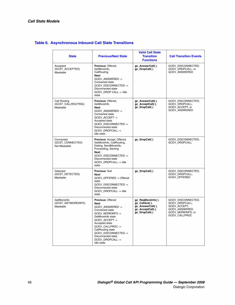
46 Dialogic® Global Call API Programming Guide — September 2008Dialogic Corporation
Call State Models
Table 6. Asynchronous Inbound Call State Transitions
State Previous/Next StateValid Call State
Transition Functions
Call Transition Events
Accepted (GCST_ACCEPTED) Maskable
Previous: Offered, GetMoreInfo, CallRoutingNext:GCEV_ANSWERED -> Connected stateGCEV_DISCONNECTED -> Disconnected stateGCEV_DROP CALL -> Idle state
gc_AnswerCall( ), gc_DropCall( )
GCEV_DISCONNECTED, GCEV_DROPCALL, or GCEV_ANSWERED
Call Routing (GCST_CALLROUTING) Maskable
Previous: Offered, GetMoreInfoNext:GCEV_ANSWERED -> Connected stateGCEV_ACCEPT -> Accepted stateGCEV_DISCONNECTED -> Disconnected stateGCEV_DROPCALL -> Idle state
gc_AnswerCall( ), gc_AcceptCall( ), gc_DropCall( )
GCEV_DISCONNECTED, GCEV_DROPCALL, GCEV_ACCEPT, or GCEV_ANSWERED
Connected (GCST_CONNECTED) Not Maskable
Previous: Accept, Offered, GetMoreInfo, CallRouting, Dialing, SendMoreInfo, Proceeding, AlertingNext: GCEV_DISCONNECTED -> Disconnected stateGCEV_DROPCALL -> Idle state
gc_DropCall( ) GCEV_DISCONNECTED, GCEV_DROPCALL
Detected (GCST_DETECTED) Maskable
Previous: NullNext:GCEV_OFFERED -> Offered stateGCEV_DISCONNECTED -> Disconnected stateGCEV_DROPCALL -> Idle state
gc_DropCall( ) GCEV_DISCONNECTED, GCEV_DROPCALL, GCEV_OFFERED
GetMoreInfo (GCST_GETMOREINFO)Maskable
Previous: OfferedNext:GCEV_ANSWERED -> Connected stateGCEV_MOREINFO -> GetMoreInfo stateGCEV_ACCEPT -> Accepted stateGCEV_CALLPROC -> CallRouting stateGCEV_DISCONNECTED -> Disconnected stateGCEV_DROPCALL -> Idle state
gc_ReqMoreInfo( ), gc_CallAck( ), gc_AnswerCall( ), gc_AcceptCall( ), gc_DropCall( )
GCEV_DISCONNECTED, GCEV_DROPCALL, GCEV_ACCEPT, GCEV_ANSWERED, GCEV_MOREINFO, or GCEV_CALLPROC

Dialogic® Global Call API Programming Guide — September 2008 47Dialogic Corporation
Call State Models
The following sections describe the asynchronous inbound call processes.
3.4.1.2 Channel Initialization
To establish calls, the following conditions must be met:
• The condition of the line device must be unblocked. When a channel is initially opened, the initial condition of a line device is blocked. A “blocking” condition on a line device is indicated by the reception of a GCEV_BLOCKED event, and an “unblocking” condition on a line device is indicated by the reception of a GCEV_UNBLOCKED event. The GCEV_BLOCKED and GCEV_UNBLOCKED events are sent as unsolicited events to the application in response to blocking alarms. GCEV_BLOCKED and GCEV_UNBLOCKED events are related to layer 1 alarms, as well as to channel states (service status in T1 ISDN, bit states in CAS). GCEV_BLOCKED and GCEV_UNBLOCKED are used as what might be termed flow-control events within the application. For more information on blocking alarms and the GCEV_BLOCKED and GCEV_UNBLOCKED events, see Section 4.3, “Blocked and Unblocked Event Handling”. When the condition of the line device is unblocked, the line device is ready for establishing calls.
• The call state of the channel must be in the Null state. This is the initial call state of a line device when it is first opened. This state is also reached when a call is released or after the channel is reset.
If the above conditions are met, the application or thread must issue a gc_WaitCall( ) function in the Null state to indicate readiness to accept an inbound call request on the specified line device. In the asynchronous mode, the gc_WaitCall( ) function must be called only once after the line device is opened using the gc_OpenEx( ) function. However, if the gc_ResetLineDev( ) function was
Null (GCST_NULL) Not Maskable
Previous: IdleNext: gc_WaitCall( ) -> Null state gc_ResetLineDev( ) -> Null stateGCEV_OFFERED -> Offered stateGCEV_DETECTED -> Detected state
gc_WaitCall( ) GCEV_DETECTED, GCEV_OFFERED
Offered (GCST_OFFERED) Not Maskable
Previous: Null, DetectedNext:GCEV_ANSWERED -> Connected stateGCEV_ACCEPT -> Accepted stateGCEV_CALLPROC -> CallRouting stateGCEV_MOREINFO -> GetMoreInfo stateGCEV_DISCONNECTED -> Disconnected stateGCEV_DROPCALL -> Idle state
gc_CallAck( ), gc_AnswerCall( ), gc_AcceptCall( ), gc_DropCall( )
GCEV_DISCONNECTED, GCEV_DROPCALL, GCEV_ACCEPT, GCEV_ANSWERED, GCEV_MOREINFO, GCEV_CALLPROC
Table 6. Asynchronous Inbound Call State Transitions (Continued)
State Previous/Next StateValid Call State
Transition Functions
Call Transition Events

48 Dialogic® Global Call API Programming Guide — September 2008Dialogic Corporation
Call State Models
issued, gc_WaitCall( ) must be reissued. In asynchronous mode, it is not necessary to issue gc_WaitCall( ) again after a call is released.
Note: After gc_WaitCall( ) is issued to wait for incoming calls on a line device, it is possible to use gc_makeCall( ) to make an outbound calls on that line device.
3.4.1.3 Call Detection
The inbound call from the network is received on the line device specified in the gc_WaitCall( ) function, but the call has not been offered to the application. The technology call control layer typically sends an acknowledgment to the remote side. In some configurations, this acknowledgment can also be sent by the application when the call is offered. At this stage, the call is being processed, which typically involves allocating resources or waiting for more information. The GCEV_DETECTED event is generated, if enabled. If the GCEV_DETECTED event is generated, a new CRN is assigned to the incoming call. This event is for informational purposes to reduce glare conditions as the application is now aware of the presence of a call on the channel.
Notes: 1. For applications that use PDK protocols, if the application enables the generation of the GCEV_DETECTED event and a call disconnects while in the Detected state, a GCEV_DISCONNECTED event is received. If the application did not enable the generation of the GCEV_DETECTED event and a call disconnects while it is in the Detected state (that is, before the call enters the Offered state), the application receives a GCEV_OFFERED event with a result value of GCRV_CALLABANDONED, then a GCEV_DISCONNECTED event.
2. When developing applications that use Dialogic® DM3 Boards, the GCEV_DETECTED event is not supported. A GCEV_DISCONNECTED event is only received if the host application already received the GCEV_OFFERED event before the remote side disconnects.
3.4.1.4 Call Offered
When an incoming call is received in en-bloc mode, where all the information required is available, the call is offered to the application by generating an unsolicited GCEV_OFFERED event (equivalent to a “ring detected” notification). This GCEV_OFFERED event causes the call to change to the Offered state. In the Offered state, a CRN is assigned as a means of identifying the call on a specific line device. If a GCEV_DETECTED event was generated before the GCEV_OFFERED event, the same CRN is assigned as the one assigned when the GCEV_DETECTED event was generated.
If the incoming call does not have sufficient information, the call is offered to the application when all the required information is received. If the technology is configured to accept minimum information, the call is offered to the application when the specified minimum amount of information is received. In this case, the application must request additional information if required. See Section 3.4.1.8, “Overlap Receiving” for more information.
A call proceeding indication can be sent by the technology call control layer, or by the application by issuing the gc_CallAck(GCACK_SERVICE_PROC) function. Otherwise, the application can accept or answer the call by issuing the gc_AcceptCall( ) or gc_AnswerCall( ) functions, respectively.
Notes: 1. For applications that use PDK protocols, if the application enables the generation of the GCEV_DETECTED event and a call disconnects while in the Detected state, a

Dialogic® Global Call API Programming Guide — September 2008 49Dialogic Corporation
Call State Models
GCEV_DISCONNECTED event is received. If the application did not enable the generation of the GCEV_DETECTED event and a call disconnects while it is in the Detected state (that is, before the call enters the Offered state), the application receives a GCEV_OFFERED event with a result value of GCRV_CALLABANDONED, then a GCEV_DISCONNECTED event.
2. When developing applications that use Dialogic® DM3 Boards, the GCEV_DETECTED event is not supported. A GCEV_DISCONNECTED event is only received if the host application already received the GCEV_OFFERED event before the remote side disconnects.
3.4.1.5 Call Routing
After the call has been offered, a call proceeding indication can be sent to the remote party to indicate that all the information has been received and the call is now proceeding. This indication can be sent by the technology call control layer or by the application by issuing the gc_CallAck(GCACK_SERVICE_PROC) function. This stage typically involves routing the call to the destination exchange or party. An information call routing tone can be played at this point to inform the remote party that the call is routing.
3.4.1.6 Call Acceptance
If the application or thread is not ready to answer the call, a gc_AcceptCall( ) function is issued to indicate to the remote end that the call was received but not yet answered. This provides an interval during which the system can verify parameters, determine routing, and perform other tasks before connecting the call. A GCEV_ACCEPT event is generated when the gc_AcceptCall( ) function is successfully completed and the call changes to the Accepted state. The application can then answer the call by issuing the gc_AnswerCall( ) function.
3.4.1.7 Call Establishment
When the call is to be directly connected, such as to a voice messaging system, or if the application or thread is ready to answer the call, a gc_AnswerCall( ) function is issued to make the final connection. Upon answering the call, a GCEV_ANSWERED event is generated and the call changes to the Connected state. At this point, the call is connected to the called party and call charges begin.
3.4.1.8 Overlap Receiving
After an incoming call has been received, the call is offered to the application based on the call acknowledgment configuration and the availability of information required for proceeding with the call. If the incoming call is in en-bloc mode where all the information required for processing the call is present, the call is offered to the application. Otherwise, the call is offered to the application based on the following configurations:
Call acknowledgment If the application is configured to send the call acknowledgment, the call is immediately offered to the application regardless of the amount of information available. The application can then request and collect more information as required. If the technology call control layer is configured to send the call acknowledgment, then the call is offered to the application based on the minimum amount of information specified.

50 Dialogic® Global Call API Programming Guide — September 2008Dialogic Corporation
Call State Models
Minimum information specified If the incoming call does not have sufficient information, the call is offered to the application based on the amount of information required. If the technology is configured to accept minimum information, the call is offered to the application only after the specified minimum amount of information is received. Thereafter, the application can request and collect more information as required. If the technology is not configured to accept minimum information, then the call is offered to the application regardless of the amount of information available. The application can then request and collect more information as required.
The following sections describe various configurations operating in overlap receiving mode.
Scenario 1
In this scenario, the application is configured to acknowledge the incoming call and send a call proceeding indication after sufficient information has been received. When an incoming call is detected, the call is immediately offered to the application regardless of the amount of information available to proceed with the call.
When the call is in the Offered state (after the generation of the unsolicited GCEV_OFFERED event), the application sends an acknowledgment for the incoming call by issuing a gc_CallAck(GCACK_SERVICE_INFO) function. The application may selectively retrieve call information, such as destination address and origination address (caller ID), by issuing the gc_GetCallInfo( ) function. If more information is still required, the gc_ReqMoreInfo( ) function is issued to request more information. When the information is received, the GCEV_MOREINFO event is generated again. When all the required information is received, the application may send a call proceeding indication to the remote side by issuing the gc_CallAck( ) function. Otherwise, the application can choose to accept or answer the call.
Scenario 2
In this scenario, the technology call control layer is configured to acknowledge the incoming call and send a call proceeding indication after sufficient information has been received. When an incoming call is detected, the technology call control layer immediately sends an acknowledgment. If the minimum amount of information required is specified, then the call is offered to the application only after the minimum amount of information required is received. After the call is offered to the application, the address information can be retrieved to determine if more information is required. If more information is required, a gc_CallAck(GCACK_SERVICE_INFO) function must be issued. Since an acknowledgment was already sent out, nothing is sent to the remote side at this time. However, if the minimum amount of information is not specified, then the technology control layer requests and collects more information. After the expected information is received, the technology control layer sends a call proceeding indication to the remote side. The call is then offered to the application, which can then accept or answer the call.
Scenario 3
In this scenario, the technology call control layer is configured to acknowledge the incoming call, and the application is configured to send a call proceeding indication after sufficient information has been received. When an incoming call is detected, the technology call control layer

Dialogic® Global Call API Programming Guide — September 2008 51Dialogic Corporation
Call State Models
immediately sends an acknowledgment. If the minimum amount of information required is specified, then the call is offered to the application only after the minimum amount of information required is received. Otherwise the call is immediately offered to the application.
When the call is in the Offered state (after generation of the unsolicited GCEV_OFFERED event), the application may selectively retrieve call information, such as the destination and origination address (caller ID), by issuing the gc_GetCallInfo( ) function. If more information is required, the application may also request more address information using the gc_CallAck(GCACK_SERVICE_INFO) function. Since an acknowledgment was already sent out, no acknowledgment is sent to the remote side at this time. When the additional information is received, the GCEV_MOREINFO event is generated. If more information is still required, the gc_ReqMoreInfo( ) function is issued to request more information. When the additional information is received, the GCEV_MOREINFO event is generated again. When all the required information is received, the application may send a call proceeding indication to the remote side by issuing the gc_CallAck(GCACK_SERVICE_PROC) function. Otherwise, the application can choose to accept or answer the call.
Scenario 4
In this scenario, the application is configured to acknowledge the incoming call, and the technology call control layer is configured to send a call proceeding indication after sufficient information has been received. When an incoming call is detected, the call is offered to the application regardless of the amount of information available.
When the call is in the Offered state (after generation of the unsolicited GCEV_OFFERED event), the application sends an acknowledgment for the incoming call by issuing a gc_CallAck(GCACK_SERVICE_INFO). The application may selectively retrieve call information, such as destination address and origination address (caller ID), by issuing the gc_GetCallInfo( ) function. If more information is still required, the gc_ReqMoreInfo( ) function is issued to request more information. When the information is received, the GCEV_MOREINFO event is generated again. When all the required information is received, the technology call control layer sends a call proceeding indication to the remote side. The application may also attempt to send a call proceeding indication to the remote side in case the technology call control layer hasn’t done so. The application can then choose to accept or answer the call.
3.4.1.9 Call Failure
The following are various causes of call failures:
Call rejection From the Offered state, the application or thread may reject the call by issuing the gc_DropCall( ) function followed by a gc_ReleaseCallEx( ) function (see the Dialogic® Global Call API Library Reference).
Forced release From the Accepted state, not all protocols support a forced release of the line, that is, issuing a gc_DropCall( ) function after a gc_AcceptCall( ) function. If a forced release is not supported and is attempted, the function will fail and an error will be returned. To recover, the application should issue the gc_AnswerCall( ) function followed by gc_DropCall( ) and

52 Dialogic® Global Call API Programming Guide — September 2008Dialogic Corporation
Call State Models
gc_ReleaseCallEx( ) functions. However, any time a GCEV_DISCONNECTED event is received in the Accepted state, the gc_DropCall( ) function can be issued.
Task failure If a call fails at any point in the call establishment process, that is, if a GCEV_TASKFAIL event is received by the application, the call stays in its current state. In most cases, the application needs to drop and release the call to return the line device to the Null state. However, in some cases, such as call failure due to a trunk error, the application needs to use the gc_ResetLineDev( ) function to reset the line device to the Null state. For more information, see the gc_DropCall( ), gc_ReleaseCallEx( ), and gc_ResetLineDev( ) function descriptions in the Dialogic® Global Call API Library Reference.
3.4.1.10 Abandoned Calls
During call establishment, the remote side may choose to hang up before call setup has been completed. The application must be capable of handling error conditions and the lack of complete information when requesting call information.
One such scenario, when using PDK protocols, is the case where the remote side chooses to disconnect a call while it is between the Detected and Offered states. The resulting behavior when the call disconnects depends on whether the application has enabled the generation of the GCEV_DETECTED event:
• If GCEV_DETECTED event generation is enabled, the application will receive a GCEV_DISCONNECTED event.
• If GCEV_DETECTED event generation is not enabled, the application will receive a GCEV_OFFERED event with a result value of GCRV_CALLABANDONED, then a GCEV_DISCONNECTED event.
Global Call uses this mechanism to can keep the application informed of the incoming, but abandoned, call.
Note: When developing applications that use Dialogic® DM3 Boards, the GCEV_DETECTED event is not supported. If the host application has not received a GCEV_OFFERED event when the call is disconnected by the remote side, the host application will not receive any event. If the host application has already received a GCEV_OFFERED event, it receives a GCEV_DISCONNECTED event when the call is disconnected.
3.4.1.11 Inbound Call Scenarios in Asynchronous Mode
This section shows various asynchronous inbound call scenarios. For call scenarios used by a specific signaling protocol, check the Dialogic® Global Call Technology Guide for that technology.
Figure 4 shows a basic asynchronous call scenario for an incoming call.

Dialogic® Global Call API Programming Guide — September 2008 53Dialogic Corporation
Call State Models
Figure 4. Basic Asynchronous Inbound Call Scenario
ApplicationGlobal Call
Library/Technology
Network
GCEV_ACCEPTED
GCEV_OFFERED
GCEV_ANSWERED
Incoming Call
(All InformationReceived)
gc_GetCallInfo(DESTINATION_ADDRESS)gc_GetCallInfo(ORIGINATION_ADDRESS)
(Sufficient Information Received)
gc_AcceptCall()
gc_AnswerCall()
Alerting
Call Answered

54 Dialogic® Global Call API Programming Guide — September 2008Dialogic Corporation
Call State Models
Figure 5 shows an asynchronous call scenario for an incoming call with call proceeding.
Figure 5. Incoming Call Scenario with Call Proceeding
ApplicationGlobal Call
Library/Technology
Network
GCEV_CALLPROC
GCEV_OFFERED
GCEV_ACCEPTED
Incoming Call
(All InformationReceived)
gc_GetCallInfo(DESTINATION_ADDRESS)gc_GetCallInfo(ORIGINATION_ADDRESS)
(Sufficient Information Received)
gc_CallAck(GCACK_SERVICE_PROC)
Alerting
Call Answered
gc_AcceptCall()
gc_AnswerCall()
GCEV_ANSWERED
Call Proceeding

Dialogic® Global Call API Programming Guide — September 2008 55Dialogic Corporation
Call State Models
Figure 6 shows an asynchronous call scenario for an incoming call with call acknowledgment and call proceeding controlled by the application.
Figure 6. Call Acknowledgment and Call Proceeding Done at the Application Layer
ApplicationGlobal Call
Library/Technology
Network
GCEV_MOREINFO
GCEV_OFFERED
Incoming Call
gc_GetCallInfo(DESTINATION_ADDRESS)gc_GetCallInfo(ORIGINATION_ADDRESS)
gc_CallAck(GCACK_SERVICE_INFO)
gc_AcceptCall()
Acknowledgementand Request forMore Address
Information
More Information
More Information
gc_ReqMoreInfo(DESTINATION_ADDRESS)
(New InformationBuffered)
GCEV_MOREINFO
gc_GetCallInfo(DESTINATION_ADDRESS)(Sufficient Information Received)
gc_GetCallInfo(DESTINATION_ADDRESS)
GCEV_CALLPROC
GCEV_ACCEPTED
GCEV_ANSWERED
gc_AnswerCall()
Call Proceeding
Alerting
Call Answered
gc_CallAck(GCACK_SERVICE_PROC)

56 Dialogic® Global Call API Programming Guide — September 2008Dialogic Corporation
Call State Models
Figure 7 shows an asynchronous call scenario for an incoming call with call proceeding controlled by the application with the minimum information configuration.
Figure 7. Call Proceeding Done by the Application Layer with Minimum Information Configured
ApplicationGlobal Call
Library/Technology
Network
GCEV_OFFERED
GCEV_DETECTEDIncoming Call
gc_GetCallInfo(DESTINATION_ADDRESS)gc_GetCallInfo(ORIGINATION_ADDRESS)
gc_AcceptCall()
Acknowledgementand Request forMore Address
Information
More Information
More Information
gc_CallAck(GCACK_SERVICE_INFO)
(New InformationBuffered)
GCEV_MOREINFO
gc_CallAck(GCACK_SERVICE_PROC)
GCEV_CALLPROC
GCEV_ACCEPTED
GCEV_ANSWERED
gc_AnswerCall()
Call Proceeding
Alerting
Call Answered
(MinimumInformationReceived)

Dialogic® Global Call API Programming Guide — September 2008 57Dialogic Corporation
Call State Models
Figure 8 shows an asynchronous call scenario for an incoming call with call acknowledgment and call proceeding controlled by the call control layer.
Figure 8. Call Acknowledgment and Call Proceeding Done at Technology Call Control Layer
ApplicationGlobal Call
Library/Technology
Network
GCEV_OFFERED
GCEV_DETECTED
Incoming Call
gc_GetCallInfo(DESTINATION_ADDRESS) /gc_GetCallInfo(ORIGINATION_ADDRESS)
Acknowledgementand Request forMore Address
Information
More Information
(All InformationReceived)
GCEV_ACCEPTED
GCEV_ANSWERED
gc_AnswerCall()
Call Proceeding
Alerting
Call Answered
(Not EnoughInformationReceived)
gc_AcceptCall()
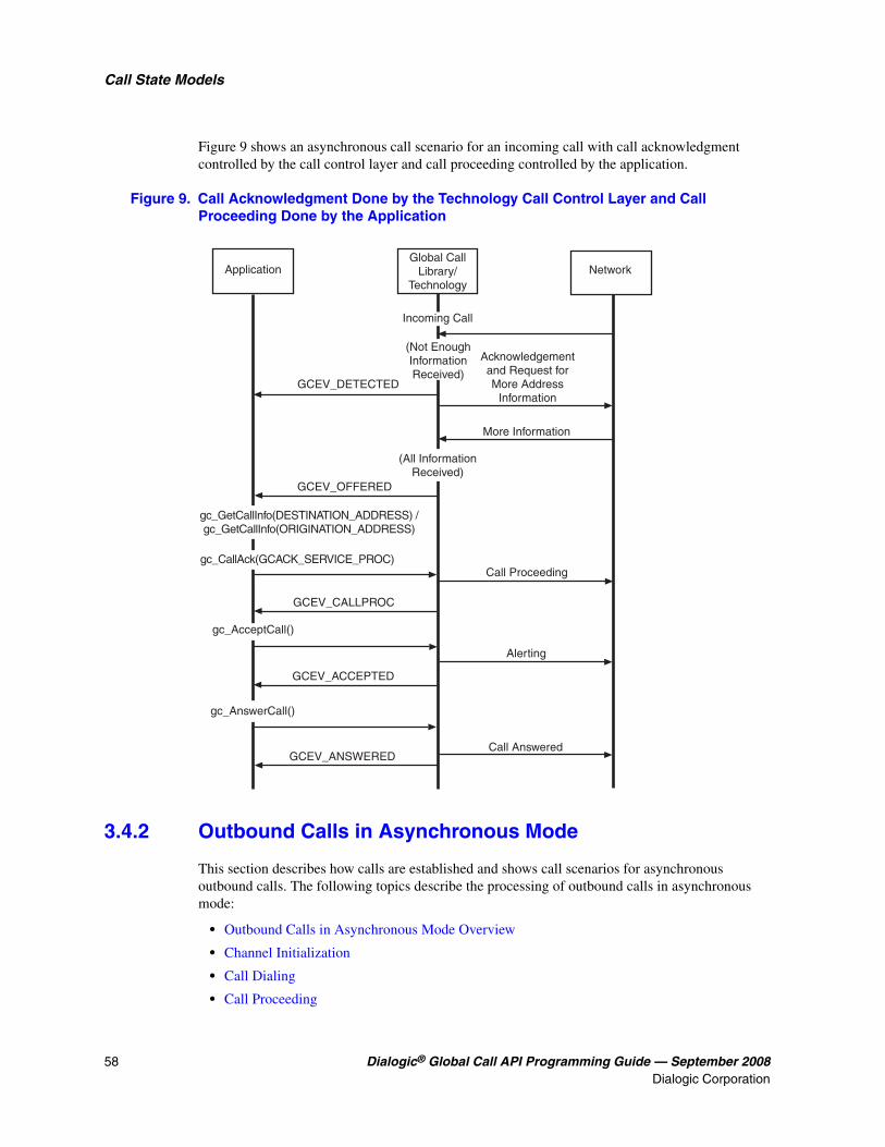
58 Dialogic® Global Call API Programming Guide — September 2008Dialogic Corporation
Call State Models
Figure 9 shows an asynchronous call scenario for an incoming call with call acknowledgment controlled by the call control layer and call proceeding controlled by the application.
Figure 9. Call Acknowledgment Done by the Technology Call Control Layer and Call Proceeding Done by the Application
3.4.2 Outbound Calls in Asynchronous Mode
This section describes how calls are established and shows call scenarios for asynchronous outbound calls. The following topics describe the processing of outbound calls in asynchronous mode:
• Outbound Calls in Asynchronous Mode Overview
• Channel Initialization
• Call Dialing
• Call Proceeding
ApplicationGlobal Call
Library/Technology
Network
GCEV_OFFERED
GCEV_DETECTED
Incoming Call
gc_GetCallInfo(DESTINATION_ADDRESS) /gc_GetCallInfo(ORIGINATION_ADDRESS)
Acknowledgementand Request forMore Address
Information
More Information
(All InformationReceived)
GCEV_ACCEPTED
GCEV_ANSWERED
gc_AnswerCall()
Call Proceeding
Alerting
Call Answered
(Not EnoughInformationReceived)
gc_AcceptCall()
gc_CallAck(GCACK_SERVICE_PROC)
GCEV_CALLPROC

Dialogic® Global Call API Programming Guide — September 2008 59Dialogic Corporation
Call State Models
• Call Alerting
• Call Connected
• Overlap Sending
• Call Failure
• Outbound Call Scenarios in Asynchronous Mode
3.4.2.1 Outbound Calls in Asynchronous Mode Overview
Figure 10 illustrates a basic Outbound Call Model, which shows the call states associated with establishing a call in the asynchronous mode. All calls start from a Null state. The call establishment process for outbound calls is shown. Table 7 presents a summary of the outbound call state transitions.

60 Dialogic® Global Call API Programming Guide — September 2008Dialogic Corporation
Call State Models
Figure 10. Basic Asynchronous Outbound Call State Diagram
GCEV_ALERTINGGCEV_ALERTING
GCEV_ALERTING
GCEV_CONNECTED
Required
Optional
GCEV_CONNECTED
GCEV_CONNECTED
GCEV_PROCEEDING
gc_MakeCall()GCEV_DIALING
(maskable)GCEV_REQMOREINFO
orgc_SendMoreInfo()
GCEV_SENDMOREINFO
GCEV_PROCEEDING
gc_SendMoreInfo()GCEV_SENDMOREINFOGCEV_REQMOREINFO
Dialing
Null
Alerting
SendMoreInfoProceeding
Connected
Legend:

Dialogic® Global Call API Programming Guide — September 2008 61Dialogic Corporation
Call State Models
The following sections describe the asynchronous outbound call processes, as shown in Figure 10, “Basic Asynchronous Outbound Call State Diagram”, on page 60.
Table 7. Asynchronous Outbound Call State Transitions
State Previous/Next StateValid Call State
Transition Functions
Call Transition Events
Alerting (GCST_ALERTING) Maskable
Previous: Proceeding, Dialing, SendMoreInfo Next:GCEV_CONNECTED -> Connected stateGCEV_DISCONNECTED -> Disconnected stateGCEV_DROPCALL -> Idle state
gc_DropCall( ) GCEV_DISCONNECTED, GCEV_DROPCALL, GCEV_CONNECTED
Dialing (GCST_DIALING) Not Maskable
Previous: Null Next: GCEV_CONNECTED -> Connected stateGCEV_ALERTING -> Alerting (Delivered) stateGCEV_PROCEEDING -> Proceeding stateGCEV_REQMOREINFO -> SendMoreInfo state GCEV_SENDMOREINFO -> SendMoreInfo state GCEV_DISCONNECTED -> Disconnected stateGCEV_DROPCALL -> Idle state
gc_SendMoreInfo( ) gc_DropCall( )
GCEV_CONNECTED, GCEV_ALERTING, GCEV_REQMOREINFO, GCEV_PROCEEDING, GCEV_DISCONNECTED, GCEV_DROPCALL
Null (GCST_NULL) Not Maskable
Previous: IdleNext:gc_ResetLineDev( ) -> NullGCEV_DIALING -> Dialing stateGCEV_DETECTED -> Detected state
gc_MakeCall( ) GCEV_DIALING
Proceeding (GCST_PROCEEDING) Maskable
Previous: Dialing, SendMoreInfo Next: GCEV_ALERTING -> Alerting (Delivered) stateGCEV_CONNECTED -> Connected stateGCEV_DISCONNECTED -> Disconnected stateGCEV_DROPCALL ->Idle state
gc_DropCall( ) GCEV_DISCONNECTED, GCEV_DROPCALL, GCEV_CONNECTED, GCEV_ALERTING
SendMoreInfo (GCST_SENDMOREINFO) Maskable
Previous: Dialing Next: GCEV_CONNECTED -> Connected stateGCEV_PROCEEDING -> Proceeding stateGCEV_DISCONNECTED -> Disconnected stateGCEV_DROPCALL -> Idle state
gc_SendMoreInfo( ) gc_DropCall( )
GCEV_DISCONNECTED, GCEV_DROPCALL, GCEV_PROCEEDING, GCEV_CONNECTED

62 Dialogic® Global Call API Programming Guide — September 2008Dialogic Corporation
Call State Models
3.4.2.2 Channel Initialization
To establish calls, the following conditions must be met:
• The condition of the line device must be unblocked. When a channel is initially opened, the initial condition of a line device is blocked. A “blocking” condition on a line device is indicated by the reception of a GCEV_BLOCKED event, and an “unblocking” condition on a line device is indicated by the reception of a GCEV_UNBLOCKED event. The GCEV_BLOCKED and GCEV_UNBLOCKED events are sent as unsolicited events to the application in response to blocking alarms. (For more information on blocking alarms and the GCEV_BLOCKED and GCEV_UNBLOCKED events, see Section 4.3, “Blocked and Unblocked Event Handling”). When the condition of the line device is unblocked, the line device is ready for establishing calls.
• The call state of the channel must be in the Null state. This is the initial call state of a line device when it is first opened. This state is also reached when a call is released or after the channel is reset by issuing the gc_ResetLineDev( ) function.
If the above conditions are met, the application is ready to make outbound calls.
3.4.2.3 Call Dialing
To initiate an outbound call using the asynchronous mode, the application issues a gc_MakeCall( ) function that requests an outgoing call to be made on a specific line device. The gc_MakeCall( ) function returns immediately. and the call state transitions to the Dialing state. The GCEV_DIALING event is generated (if enabled) to indicate that the call has transitioned to the Dialing state. A CRN is assigned to the call being established on that line device. If the gc_MakeCall( ) function fails, the line device remains in the Null state. In this state, dialing information is sent to the remote side.
3.4.2.4 Call Proceeding
In the Dialing state, the remote side may indicate that all the information was received and the call is proceeding. In this case, the GCEV_PROCEEDING event is generated and the call transitions to the Proceeding state. The remote side may either accept or answer the call.
3.4.2.5 Call Alerting
If the remote end is not ready to answer the call, a GCEV_ALERTING event is generated. This event indicates that the called party has accepted but not answered the call and that the network is waiting for the called party to complete the connection. At this stage, the remote side is typically ringing. This GCEV_ALERTING event changes the call state to the Alerting state.
3.4.2.6 Call Connected
When the called party immediately accepts the call, such as a call directed to a fax or voice messaging system, a GCEV_CONNECTED event is generated to indicate that the connection was established. This event changes the call to the Connected state. In the Connected state, the call is connected to the called party and call charges begin.

Dialogic® Global Call API Programming Guide — September 2008 63Dialogic Corporation
Call State Models
When the call is answered (the remote end makes the connection), a GCEV_CONNECTED event changes the call to the Connected state. In the Connected state, the call is connected to the called party and call charges begin. The GCEV_CONNECTED event indicates successful completion of the gc_MakeCall( ) function.
3.4.2.7 Overlap Sending
In the Dialing state, if the remote side requests more information such as the destination address, the GCEV_REQMOREINFO event is generated and the call transitions to the SendMoreInfo state. The gc_SendMoreInfo( ) function is issued to send more information. If the remote side still requests more information, the GCEV_REQMOREINFO event is generated again. Once the remote side has received sufficient information, it indicates that the call is proceeding, and accepts or answers the call. Some technologies, such as ISDN and SS7, do not have any messages or signals to request more information. For such protocols, the application never gets the unsolicited GCEV_REQMOREINFO event. In this case, the application may call the gc_SendMoreInfo( ) function to send more information as it becomes available.
3.4.2.8 Call Failure
The following are two causes of call failures:
Call rejection When the remote end does not answer the call, a GCEV_DISCONNECTED event is generated. This event is also generated when an inbound call arrives while the application is setting up an outbound call, causing a “glare” condition. Unless the protocol specifies otherwise, the incoming call takes precedence over the outbound call. When an asynchronous gc_MakeCall( ) function conflicts with the arrival of an inbound call, all the resources need to be released for the outbound call. Subsequently, the GCEV_DISCONNECTED event is generated with a result value indicating that an inbound call took precedence. The gc_DropCall( ) function must be issued after the GCEV_DISCONNECTED event is received.
If a gc_MakeCall( ) function is issued while the inbound call is being set up, the gc_MakeCall( ) function fails. The inbound call event is held in the driver until the CRN of the outbound call is released using the gc_ReleaseCallEx( ) function. After release of the outbound CRN, the pending inbound call event is sent to the application. This behavior may be modified by the individual protocol specification.
Task failure If the gc_MakeCall( ) cannot be completed successfully, a GCEV_TASKFAIL event or a GCEV_DISCONNECTED event is sent to the application. The result value associated with the event indicates the reason for the event. If the GCEV_TASKFAIL event is sent, then a problem occurred when placing the call from the local end.
3.4.2.9 Outbound Call Scenarios in Asynchronous Mode
This section shows various asynchronous outbound call scenarios. For call scenarios used for a specific signaling protocol, check the appropriate Dialogic® Global Call Technology Guide for that technology.
Figure 11 shows a basic asynchronous call scenario for outgoing calls.

64 Dialogic® Global Call API Programming Guide — September 2008Dialogic Corporation
Call State Models
Figure 11. Asynchronous Outbound Call Scenario
Figure 12 shows an asynchronous call scenario for outgoing calls with call acknowledgment.
Figure 12. Asynchronous Outbound Call Scenario with Call Acknowledgment
ApplicationGlobal Call
Library/Technology
Network
GCEV_DIALING
Outbound Call
Alerting
Call Answered
gc_MakeCall ()
GCEV_ALERTING
GCEV_CONNECTED
ApplicationGlobal Call
Library/Technology
Network
GCEV_PROCEEDING
Outbound Call
Alerting
Call Answered
gc_MakeCall ()
GCEV_ALERTING
GCEV_CONNECTED
GCEV_DIALING
Call Proceeding

Dialogic® Global Call API Programming Guide — September 2008 65Dialogic Corporation
Call State Models
Figure 13 shows an asynchronous call scenario for outgoing calls with overlap sending.
Figure 13. Asynchronous Outbound Call Scenario with Overlap Sending
3.4.3 Call Termination in Asynchronous Mode
This section describes how calls are terminated and shows call scenarios for asynchronous call termination. The following topics describe call termination in asynchronous mode:
• Call Termination in Asynchronous Mode Overview
• User Initiated Termination
• Network Initiated Termination
• Call Release
• Call Termination Call Control Scenarios in Asynchronous Mode
3.4.3.1 Call Termination in Asynchronous Mode Overview
Figure 14 illustrates the call states associated with call termination or call teardown in the asynchronous mode initiated by either a call disconnection or failure. See Table 8 for a summary of
ApplicationGlobal Call
Library/Technology
Network
GCEV_SENDMOREINFO
Outbound Call
Alerting
Call Answered
gc_MakeCall ()
GCEV_ALERTING
GCEV_CONNECTED
GCEV_DIALING
Request MoreAddress Information
GCEV_REQMOREINFO
gc_SendMoreInfo (DESTINATION_ADDRESS)
Call Proceeding
GCEV_PROCEEDING
More AddressInformation

66 Dialogic® Global Call API Programming Guide — September 2008Dialogic Corporation
Call State Models
the call state transitions. A call can be terminated by the application or by the detection of a call disconnect from the network. Either of these terminations can occur at any point in the process of setting up a call and during any call state.
Figure 14. Asynchronous Call Tear-Down State Diagram
gc_DropCall()GCEV_DROPCALL
GCEV_DISCONNECTED
From Any StateShown Below
From Any StateShown Below
TERMINATEDBY NETWORK
TERMINATEDBY APPLICATION
gc_DropCall()GCEV_DROPCALL
Disconnected
Idle
Null
Dialing
Offered
Accepted
Connected
GetMoreInfo
SendMoreInfo
CallRouting
Proceeding
Alerting
Dialing
Offered
Accepted
Connected
GetMoreInfo
SendMoreInfo
CallRouting
Proceeding
Alerting
gc_ReleaseCall()gc_ReleaseCallEx()GCEV_RELEASECALL
Detected * Detected *
Note: * applies if the application requested to be notified of GCEV_DETECTED events.

Dialogic® Global Call API Programming Guide — September 2008 67Dialogic Corporation
Call State Models
3.4.3.2 User Initiated Termination
The application terminates a call by issuing a gc_DropCall( ) function that initiates disconnection of the call specified by the CRN. When the remote side responds by disconnecting the call, a GCEV_DROPCALL event is generated and causes a transition from the current call state to the Idle state. The user must then issue the gc_ReleaseCallEx( ) function to release all internal resources allocated for the call.
3.4.3.3 Network Initiated Termination
When a network call termination is initiated, an unsolicited GCEV_DISCONNECTED event is generated. This event indicates the call was disconnected at the remote end or an error was detected, which prevented further call processing. The GCEV_DISCONNECTED event causes the call state to change from the current call state to the Disconnected state. This event may be received during call setup or after a connection is requested. In the Disconnected state, the user issues the gc_DropCall( ) function to disconnect the call. The gc_DropCall( ) function is equivalent to set hook ON. After the remote side is notified about the call being dropped, a GCEV_DROPCALL event is generated causing the call state to change to the Idle state. In the Idle state, the gc_ReleaseCallEx( ) function must be issued to release all internal resources committed to servicing the call.
3.4.3.4 Call Release
Once in the Idle state, the call has been disconnected and the application must issue a gc_ReleaseCallEx( ) function to free the line device for another call. The gc_ReleaseCallEx( ) function releases all internal system resources committed to servicing the call. A GCEV_RELEASECALL event is generated and the call state transitions to the Null state.
Table 8. Asynchronous Call Termination Call State Transitions
State Previous/Next StateValid Call State
Transition FunctionsCall Transition Events
Disconnected (GCEV_DISCONNECTED)Not maskable
Previous: Offered, Accepted, Connected, Dialing, SendMoreInfo, Proceeding, Alerting, GetMoreInfo, CallRoutingNext:GCEV_DROPCALL -> Idle state
gc_DropCall( ) GCEV_DROPCALL
Idle (GCST_IDLE) Not Maskable
Previous: Offered, Accepted, Connected, Dialing, SendMoreInfo, Proceeding, Alerting, GetMoreInfo, CallRouting, DisconnectedNext:GCEV_RELEASECALL -> Null
gc_ReleaseCallEx( ) GCEV_RELEASECALL

68 Dialogic® Global Call API Programming Guide — September 2008Dialogic Corporation
Call State Models
3.4.3.5 Call Termination Call Control Scenarios in Asynchronous Mode
This section shows various asynchronous call termination call scenarios. For call scenarios used for a specific signaling protocol, check the appropriate Dialogic® Global Call Technology Guide for that technology.
Figure 15 shows an asynchronous user initiated call termination scenario.
Figure 15. User Initiated Asynchronous Call Termination Scenario
Figure 16 shows an asynchronous network initiated call termination scenario.
Figure 16. Network Initiated Asynchronous Call Termination Scenario
ApplicationGlobal Call
Library/Technology
Network
Disconnectgc_DropCall ()
GCEV_RELEASECALL
GCEV_DROPCALL
Call Disconnectedgc_ReleaseCallEx()
ApplicationGlobal Call
Library/Technology
Network
Call Disconnected
GCEV_DROPCALL
GCEV_RELEASECALL
GCEV_DISCONNECTED
Disconnected
gc_DropCall()
gc_ReleaseCallEx ()
Dialogic® Global Call API Programming Guide — September 2008 69Dialogic Corporation
Call State Models
3.5 Basic Call Control in Synchronous Mode
This section describes and illustrates the basic call model and state transitions for call control in the synchronous mode. This section also describes the process for call establishment for both inbound and outbound calls and call termination in the synchronous mode.
The procedures for establishing and terminating calls in the synchronous mode are described in the following sections:
• Inbound Calls in Synchronous Mode
• Outbound Calls in Synchronous Mode
• Call Termination in Synchronous Mode
The application must handle unsolicited events in the synchronous mode, unless these events are masked or disabled. Procedures for handling unsolicited events are described in Section 3.5.4, “Handling Unsolicited Events”.
3.5.1 Inbound Calls in Synchronous Mode
This section describes how calls are established and shows call scenarios for synchronous inbound calls. The following topics describe the processing of inbound calls in synchronous mode:
• Inbound Calls in Synchronous Mode Overview
• Channel Initialization
• Call Offered
• Call Routing
• Call Acceptance
• Call Establishment
• Overlap Receiving
• Call Failure
• Inbound Call Scenarios in Synchronous Mode
3.5.1.1 Inbound Calls in Synchronous Mode Overview
Figure 17 illustrates a Basic Call Model, and indicates the call states associated with establishing or setting up a call in the synchronous mode. The call establishment process for inbound calls is shown. All calls start from a Null state. See Table 9 for a summary of the call state transitions.
Some features, such as overlap sending/receiving, are not supported in the synchronous mode. Typically, synchronous calls are made when the application does not care about the intermediate function calls or events required for establishing a call. However, the overlap feature requires intermediate state transitions where additional function calls need to be made. Previously, functions returned upon successful completion; but in the overlap mode, they may return before successful completion, possibly due to an intermediate request for more information.
Note: The Advanced Call Model includes call states associated with holding, retrieving, and transferring calls. See Section 3.6, “Advanced Call Control with Call Hold and Transfer” for more information.

70 Dialogic® Global Call API Programming Guide — September 2008Dialogic Corporation
Call State Models
Figure 17. Basic Synchronous Inbound Call State Diagram
gc_WaitCall()(maskable)
gc_AcceptCall()
gc_AcceptCall()
gc_AcceptCall()
gc_AnswerCall()
Required
Optional
gc_AnswerCall()
gc_AnswerCall()
gc_CallAck(MORE_INFO)
gc_WaitCall()
gc_CallAck(CALL_PROC)
gc_CallAck(CALL_PROC)
gc_ReqMoreInfo()
Detected
Offered
Null
Accepted
CallRoutingGetMoreInfo
Connected
Legend:

Dialogic® Global Call API Programming Guide — September 2008 71Dialogic Corporation
Call State Models
Table 9. Synchronous Inbound Call State Transitions
State Previous/Next StateValid Call State
Transition Functions
Call Transition Events
Accepted (GCST_ACCEPTED)
Maskable
Previous: Offered, GetMoreInfo, CallRouting
Next:
gc_AnswerCall( ) -> Connected state
GCEV_DISCONNECTED -> Disconnected state
gc_DropCall( ) -> Idle state
gc_AnswerCall( ), gc_DropCall( )
GCEV_DISCONNECTED
Call Routing (GCST_CALLROUTING)
Maskable
Previous: Offered, GetMoreInfo
Next:
gc_AnswerCall( ) -> Connected state
gc_AcceptCall( ) -> Accepted state
GCEV_DISCONNECTED -> Disconnected state
gc_DropCall( ) -> Idle state
gc_AnswerCall( ), gc_AcceptCall( ), gc_DropCall( )
GCEV_DISCONNECTED
Connected (GCST_CONNECTED)
Not Maskable
Previous: Accept, Offered, GetMoreInfo, CallRouting, Dialing, SendMoreInfo, Proceeding, Alerting
Next:
GCEV_DISCONNECTED -> Disconnected state
gc_DropCall( ) -> Idle state
gc_DropCall( ) GCEV_DISCONNECTED
GetMoreInfo (GCST_GETMOREINFO)
Maskable
Previous: Offered
Next:
gc_AnswerCall( ) -> Connected state
gc_AcceptCall( ) -> Accepted state
gc_CallAck( ) sends CallProceeding -> CallRouting state
gc_ReqMoreInfo( ) -> GetMoreInfo state
GCEV_DISCONNECTED -> Disconnected state
gc_DropCall( ) -> Idle state
gc_ReqMoreInfo( ), gc_CallAck( ), gc_AnswerCall( ), gc_AcceptCall( ), gc_DropCall( )
GCEV_DISCONNECTED

72 Dialogic® Global Call API Programming Guide — September 2008Dialogic Corporation
Call State Models
3.5.1.2 Channel Initialization
To establish calls, the following conditions must be met:
• The condition of the line device must be unblocked. When a channel is initially opened, the initial condition of a line device is blocked. A “blocking” condition on a line device is indicated by the reception of a GCEV_BLOCKED event, and an “unblocking” condition on a line device is indicated by the reception of a GCEV_UNBLOCKED event. The GCEV_BLOCKED and GCEV_UNBLOCKED events are sent as unsolicited events to the application in response to blocking alarms. For more information on blocking alarms and the GCEV_BLOCKED and GCEV_UNBLOCKED events, see Section 4.3, “Blocked and Unblocked Event Handling”. When the condition of the line device is unblocked, the line device is ready for establishing calls.
• The call state of the channel must be in the Null state. This is the initial call state of a line device when it is first opened. This state is also reached when a call is released or after the channel is reset.
If the above conditions are met, the application must issue a gc_WaitCall( ) function in the Null state to indicate readiness to accept an inbound call request on the specified line device. In the synchronous mode, the gc_WaitCall( ) function waits for an inbound call for the length of time specified by the timeout parameter. When the timeout expires, the function fails with an error code, EGC_TIMEOUT, and must be reissued. If the time specified is 0, the function fails unless a call is already pending on the specified line device.
Null (GCST_NULL)
Not Maskable
Previous: Idle
Next:
gc_WaitCall( ) -> Offered state
gc_WaitCall( ) GCEV_DETECTED
Offered (GCST_OFFERED)
Not Maskable
Previous: Null, Detected
Next:
gc_AnswerCall( ) -> Connected state
gc_AcceptCall( ) ->Accepted state
gc_CallAck( ) sends CallProceeding -> CallRouting state
gc_CallAck( ) requests more info -> GetMoreInfo state
GCEV_DISCONNECTED -> Disconnected state
gc_DropCall( ) -> Idle state
gc_CallAck( ), gc_AnswerCall( ), gc_AcceptCall( ), gc_DropCall( )
GCEV_DISCONNECTED
Table 9. Synchronous Inbound Call State Transitions (Continued)
State Previous/Next StateValid Call State
Transition Functions
Call Transition Events

Dialogic® Global Call API Programming Guide — September 2008 73Dialogic Corporation
Call State Models
A gc_WaitCall( ) function waiting for a call to arrive can be stopped (terminated) by issuing the gc_ResetLineDev( ) function. When the gc_WaitCall( ) function fails or is stopped, all system resources including the CRN assigned to the call are released. To accept inbound calls, another gc_WaitCall( ) function must be issued each time the application wishes to receive an inbound call. The application blocks to wait for an incoming call by issuing the gc_WaitCall( ) function. The application must repeat the poll for incoming calls by issuing the gc_WaitCall( ) function each time it polls for a call.
3.5.1.3 Call Offered
The inbound call from the network is received on the specified line device but is not yet offered to the application, which causes the call state to change to the Detected state, if supported. At this stage, the call is being processed, which typically involves allocating resources or waiting for more information. If the call does change to the Detected state, no GCEV_DETECTED event is generated and the gc_WaitCall( ) function does not return until the call is offered to the application. After all the required processing is done, the call is offered to the application and the call state changes to the Offered state. The application may selectively retrieve call information, such as destination address and origination address (caller ID). If more information is required (overlap receiving) or the call needs to be acknowledged, the gc_CallAck( ) function must be issued. (See Section 3.5.1.7, “Overlap Receiving”.) Otherwise, the user can accept or answer the call by issuing gc_AcceptCall( ) or gc_AnswerCall( ) respectively.
3.5.1.4 Call Routing
After the call has been offered, the gc_CallAck(GCACK_SERVICE_PROC) function can be issued to indicate to the other side that all the information has been received and the call is now proceeding. This stage typically involves routing the call to the destination exchange or party. An information call routing tone can be played at this point to inform the remote party that the call is routing.
3.5.1.5 Call Acceptance
If the application is not ready to answer the call, a gc_AcceptCall( ) function is issued to indicate to the remote end that the call was received but not yet answered. This provides an interval during which the system can verify parameters, determine routing, and perform other tasks before connecting the call. When the gc_AcceptCall( ) function is successfully completed, the call changes to the Accepted state. The application may selectively retrieve call information, such as the destination address and origination address (caller ID). The application can then answer the call by issuing the gc_AnswerCall( ) function.
3.5.1.6 Call Establishment
When the call is to be directly connected, such as to a voice messaging system, the gc_AnswerCall( ) function is issued to make the final connection. When the gc_AnswerCall( ) function is successfully completed, the call changes to the Connected state. At this time, the call is connected to the called party and call charges begin.

74 Dialogic® Global Call API Programming Guide — September 2008Dialogic Corporation
Call State Models
3.5.1.7 Overlap Receiving
After an incoming call has been received, the call is offered to the application based on the call acknowledgment configuration and the availability of information required for proceeding with the call. If the incoming call is in en-bloc mode where all the information required for processing the call is present, the call is offered to the application. Otherwise, the call is offered to the application based on the following:
Call acknowledgment If the application is configured to send the call acknowledgment, the call is immediately offered to the application regardless of the amount of information available. The application can then request and collect more information as required. If the technology call control layer is configured to send the call acknowledgment, then the call is offered to the application based on the minimum amount of information specified.
Minimum information specified If the incoming call does not have sufficient information, the call is offered to the application based on the amount of information required. If the technology is configured to accept minimum information, the call is offered to the application only after the specified minimum amount of information is received. Thereafter, the application can request and collect more information as required. If the technology is not configured to accept minimum information, then the call is offered to the application regardless of the amount of information available. The application can then request and collect more information as required.
The following sections describe various configurations operating in overlap receiving mode.
Scenario 1
In this scenario, the application is configured to acknowledge the incoming call and send a call proceeding indication after sufficient information has been received. When an incoming call is detected, the call is immediately offered to the application regardless of the amount of information available to proceed with the call.
When the call is in the Offered state, the application sends an acknowledgment for the incoming call by issuing a gc_CallAck(GCACK_SERVICE_INFO). The application may selectively retrieve call information, such as destination address and origination address (caller ID), by issuing gc_GetCallInfo( ). If more information is still required, the gc_ReqMoreInfo( ) function is issued to request more information. The function returns when the requested information is received. The application may then send a call proceeding indication to the remote side by issuing the gc_CallAck(GCACK_SERVICE_PROC) function. Otherwise, the application can choose to accept or answer the call.
Scenario 2
In this scenario, the technology call control layer is configured to acknowledge the incoming call and send a call proceeding indication after sufficient information has been received. When an incoming call is detected, the technology call control layer immediately sends an acknowledgment.
If the minimum amount of information required is specified, then the call is offered to the application only after the minimum amount of information required is received. When the call is

Dialogic® Global Call API Programming Guide — September 2008 75Dialogic Corporation
Call State Models
offered to the application and more information is required, the gc_CallAck(GCACK_SERVICE_INFO) must be issued. Since an acknowledgment was already sent out, no acknowledgment is sent to the remote side at this time. However, if the minimum amount of information is not specified, then the technology control layer requests and collects more information. After all the information is received, the technology control layer sends a call proceeding indication to the remote side. The call is then offered to the application, which can then accept or answer the call.
Scenario 3
In this scenario, the technology call control layer is configured to acknowledge the incoming call and the application is configured to send a call proceeding indication after sufficient information has been received. When an incoming call is detected, the technology call control layer immediately sends an acknowledgment.
If the minimum amount of information required is specified, then the call is offered to the application only after the minimum amount of information required is received. Otherwise the call is immediately offered to the application.
When the call is in the Offered state, the application may selectively retrieve call information, such as destination address and origination address (caller ID), by issuing the gc_GetCallInfo( ) function. If more information is required, the application may also request more address information using the gc_CallAck(GCACK_SERVICE_INFO) function. This function returns when the requested information is received. If more information is still required, the gc_ReqMoreInfo( ) function is issued to request more information. When all the required information is received, the application may send a call proceeding indication to the remote side by issuing the gc_CallAck(GCACK_SERVICE_PROC) function. Otherwise, the application can choose to accept or answer the call.
Scenario 4
In this scenario, the application is configured to acknowledge the incoming call and the technology call control layer is configured to send a call proceeding indication after sufficient information has been received. When an incoming call is detected, the call is offered to the application regardless of the amount of information available.
When the call is in the Offered state (after generation of the unsolicited GCEV_OFFERED event), the application sends an acknowledgment for the incoming call by issuing a gc_CallAck(GCACK_SERVICE_INFO). The application may selectively retrieve call information, such as the destination address and origination address (caller ID), by issuing the gc_GetCallInfo( ) function. If more information is still required, the gc_ReqMoreInfo( ) function is issued to request more information. This function returns when the requested information is received. When all the required information is received, the technology call control layer sends a call proceeding indication to the remote side. The application may also attempt to send a call proceeding indication to the remote side in case the technology call control layer hasn’t done so. The application can then choose to accept or answer the call.

76 Dialogic® Global Call API Programming Guide — September 2008Dialogic Corporation
Call State Models
3.5.1.8 Call Failure
The following are various causes of call failures:
Call rejection From the Offered state, the application may reject the call by issuing the gc_DropCall( ) function followed by the gc_ReleaseCallEx( ) function.
Forced release From the Accepted state, not all E1 CAS protocols support a forced release of the line. that is, issuing the gc_DropCall( ) function after the gc_AcceptCall( ) function. If a forced release is attempted, the function fails, and an error is returned. To recover, the application should issue the gc_AnswerCall( ) function followed by the gc_DropCall( ) and gc_ReleaseCallEx( ) functions. However, anytime a GCEV_DISCONNECTED event is received in the Accepted state, the gc_DropCall( ) function can be issued.
Task failure If a call fails at any point in the call establishment process, the call stays in its current state. In most cases, the application needs to drop and release the call to return the line device to the Null state. However, in some cases, such as call failure due to a trunk error, the application needs to use the gc_ResetLineDev( ) function to reset the line device to the Null state. For more information, see the gc_DropCall( ), gc_ReleaseCallEx( ), and gc_ResetLineDev( ) function descriptions in the Dialogic® Global Call API Library Reference.
3.5.1.9 Inbound Call Scenarios in Synchronous Mode
The following shows the various synchronous inbound call scenarios. For call scenarios used for a specific signaling protocol, check the Dialogic® Global Call Technology Guide for that technology.
Figure 18 shows a basic synchronous call scenario for an incoming call.
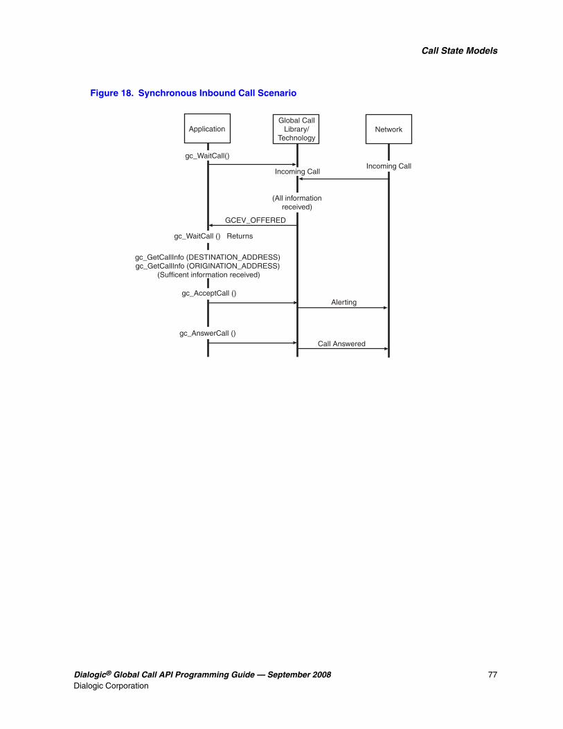
Dialogic® Global Call API Programming Guide — September 2008 77Dialogic Corporation
Call State Models
Figure 18. Synchronous Inbound Call Scenario
ApplicationGlobal Call
Library/Technology
Network
Alerting
GCEV_OFFERED
Incoming CallIncoming Call
gc_WaitCall()
(All informationreceived)
gc_GetCallInfo (DESTINATION_ADDRESS)gc_GetCallInfo (ORIGINATION_ADDRESS)
(Sufficent information received)
gc_WaitCall () Returns
Call Answered
gc_AcceptCall ()
gc_AnswerCall ()

78 Dialogic® Global Call API Programming Guide — September 2008Dialogic Corporation
Call State Models
Figure 19 shows a basic synchronous call scenario for an incoming call with call acknowledgment.
Figure 19. Synchronous Inbound Call Scenario with Call Acknowledgment
ApplicationGlobal Call
Library/Technology
Network
Alerting
GCEV_OFFERED
Incoming Call
gc_WaitCall()
(All informationreceived)
gc_GetCallInfo (DESTINATION_ADDRESS)/gc_GetCallInfo (ORIGINATION_ADDRESS)
(Sufficent information received)
gc_WaitCall () Returns
Call Answered
gc_CallAck (GCACK_SERVICE_PROC)
gc_AnswerCall ()
gc_AcceptCall ()
Call Proceeding

Dialogic® Global Call API Programming Guide — September 2008 79Dialogic Corporation
Call State Models
Figure 20 shows a basic synchronous call scenario for an incoming call with overlap receiving.
Figure 20. Synchronous Inbound Call Scenario with Overlap Receiving
3.5.2 Outbound Calls in Synchronous Mode
This section describes how calls are established and shows a call scenario for synchronous outbound calls. The following topics describe the processing of outbound calls in synchronous mode:
• Outbound Calls in Synchronous Mode Overview
• Channel Initialization
• Call Dialing
• Call Proceeding
• Call Alerting
• Call Connected
• Outbound Call Scenario in Synchronous Mode
ApplicationGlobal Call
Library/Technology
Network
Alerting
GCEV_OFFERED
Incoming Call
gc_WaitCall()
(New InformationBuffered)
gc_GetCallInfo (DESTINATION_ADDRESS)/gc_GetCallInfo (ORIGINATION_ADDRESS)
gc_WaitCall () Returns
Call Answered
gc_CallAck (GCACK_SERVICE_PROC)
gc_AnswerCall ()
gc_AcceptCall ()Call Proceeding
gc_CallAck (GCACK_SERVICE_INFO) returns
gc_GetCallInfo (DESTINATION_ADDRESS)(Sufficient information received)
gc_CallAck (GCACK_SERVICE_PROC)
More Information
More Information
Request More Adddress Information
gc_ReqMoreInfo (DESTINATION ADDRESS)

80 Dialogic® Global Call API Programming Guide — September 2008Dialogic Corporation
Call State Models
3.5.2.1 Outbound Calls in Synchronous Mode Overview
Figure 21 shows the outbound synchronous call model states. Table 10 shows a summary of call state transitions.
The overlap sending/receiving feature is not supported in the outbound synchronous call model. Typically, synchronous calls are made when the application does not need the intermediate function calls or events for establishing a call. However, the overlap feature requires intermediate state transitions where additional function calls need to be made. In addition, synchronous functions always return upon successful completion. But in the overlap mode, functions must return before successful completion due to an intermediate request for more information. Handling all the possible cases can complicate the synchronous model.
Figure 21. Outbound Synchronous Call Process
gc_MakeCall()
Call is Answered
Null
GCEV_PROCEEDING
GCEV_ALERTING
GCEV_ALERTING
Dialing
Call is Answered
Alerting
Connected
Proceeding

Dialogic® Global Call API Programming Guide — September 2008 81Dialogic Corporation
Call State Models
3.5.2.2 Channel Initialization
In order to establish calls, the following conditions must be met:
• The condition of the line device must be unblocked. When a channel is initially opened, the initial condition of a line device is blocked. A “blocking” condition on a line device is indicated by the reception of a GCEV_BLOCKED event, and an “unblocking” condition on a line device is indicated by the reception of a GCEV_UNBLOCKED event. The GCEV_BLOCKED and GCEV_UNBLOCKED events are sent as unsolicited events to the application in response to blocking alarms. For more information on blocking alarms and the GCEV_BLOCKED and GCEV_UNBLOCKED events, see Section 4.3, “Blocked and Unblocked Event Handling”. When the condition of the line device is unblocked, the line device is ready for establishing calls.
• The call state of the channel must be in the Null state. This is the initial call state of a line device when it is first opened. This state is also reached when a call is released or after the channel is reset by issuing gc_ResetLineDev( ).
If the above conditions are met, the application is ready to receive inbound calls.
3.5.2.3 Call Dialing
To initiate an outbound call (see Figure 21 and Table 10) using the synchronous mode, the application issues the gc_MakeCall( ) function, which requests an outgoing call to be made on a specific line device. A CRN is assigned to the call being made on the specific line device. Dialing information is then sent to and acknowledged by the network. When the gc_MakeCall( ) function is issued in the synchronous mode, the function returns successfully when the call reaches the
Table 10. Synchronous Outbound Call State Transitions
State Previous/Next StateValid Call State
Transition Functions
Call Transition Events
Alerting (GCST_ALERTING)
Maskable
Previous: Proceeding, Dialing, SendMoreInfo
Next:
gc_DropCall( ) -> Idle state
gc_DropCall( ) GCEV_DISCONNECTED
Dialing (GCST_DIALING)
Maskable
Previous: Null
Next:
gc_DropCall( ) -> Idle state
gc_DropCall( ) GCEV_ALERTING, GCEV_DISCONNECTED
Null (GCST_NULL)
Not Maskable
Previous: Idle
Next:
gc_MakeCall( ) -> Dialing state
gcDropCall( ) -> Idle state
gc_MakeCall( )
Proceeding (GCST_PROCEEDING)
Not Maskable
Previous: Dialing, SendMoreInfo
Next:
gc_DropCall( ) -> Idle state
gc_DropCall( ) GCEV_DISCONNECTED, GCEV_ALERTING

82 Dialogic® Global Call API Programming Guide — September 2008Dialogic Corporation
Call State Models
Connected state. See the Dialogic® Global Call Technology Guide for your technology for valid completion points for the gc_MakeCall( ) function.
Some call related events indicating the status of the call may be generated, if enabled, while the gc_MakeCall( ) function is in progress.
3.5.2.4 Call Proceeding
The remote side may indicate that all the information was received and that the call is proceeding. In this case, the GCEV_PROCEEDING event is generated, if enabled, and the call transitions to the Proceeding state. The remote side may either accept or answer the call.
3.5.2.5 Call Alerting
If the remote end is not ready to answer the call, the GCEV_ALERTING event is generated, if enabled. This event indicates that the called party has accepted but not answered the call, and that the network is waiting for the called party to complete the connection. At this stage, the remote side is typically ringing. This GCEV_ALERTING event changes the call state to the Alerting state.
3.5.2.6 Call Connected
When the call is answered (the remote end makes the connection), the gc_MakeCall( ) function completes successfully and the call changes to the Connected state.
3.5.2.7 Outbound Call Scenario in Synchronous Mode
Figure 22 shows a synchronous outbound call scenario. For call scenarios used for a specific signaling protocol, check the Dialogic® Global Call Technology Guide for that technology.
Figure 22. Outbound Call Scenario in Synchronous Mode
ApplicationGlobal Call
Library/Technology
Network
Alerting
GCEV_RPOCEEDING
gc_MakeCall()
Call Answered
Call Proceeding
Outbound Call
GCEV_ALERTING
GCEV_CONNECTED

Dialogic® Global Call API Programming Guide — September 2008 83Dialogic Corporation
Call State Models
3.5.3 Call Termination in Synchronous Mode
This section describes how calls are terminated and shows call scenarios for synchronous call terminations. The following topics describe the processing of call termination in synchronous mode:
• Call Termination in Synchronous Mode Overview
• User Initiated Termination
• Network Initiated Termination
• Call Release
• Call Termination Call Control Scenarios in Synchronous Mode
3.5.3.1 Call Termination in Synchronous Mode Overview
Figure 23 illustrates the call states associated with call termination or call tear-down in the synchronous mode, initialized by either call disconnection or failure. Table 11 summarizes the call state transitions. A call can be terminated by the application or by detection of a call disconnect from the network. Either of these terminations can occur at any point in the process of setting up a call and during any call state.

84 Dialogic® Global Call API Programming Guide — September 2008Dialogic Corporation
Call State Models
Figure 23. Synchronous Call Tear-Down State Diagram
gc_ReleaseCallEx()
gc_DropCall()
GCEV_DISCONNECTED
From Any StateShown Below
From Any StateShown Below
See the Global Call CDP ConfigurationGuide for the protocols that support a forced release of the line.
*
TERMINATEDBY NETWORK
TERMINATEDBY APPLICATION
gc_DropCall()
Disconnected
Idle
Null
Offered
Accepted
Connected
Alerting
GetMoreInfo
CallRouting
Offered
Accepted*
Connected
Alerting
GetMoreInfo
CallRouting

Dialogic® Global Call API Programming Guide — September 2008 85Dialogic Corporation
Call State Models
3.5.3.2 User Initiated Termination
The application terminates a call by issuing a gc_DropCall( ) function that initiates disconnection of the call specified by the CRN. This gc_DropCall( ) function causes the call to change from the current call state to the Idle state. In the Idle state, the call has been disconnected and the application must issue a gc_ReleaseCallEx( ) function to free the line device for another call. This gc_ReleaseCallEx( ) function instructs the driver and firmware to release all system resources committed to servicing the call, and causes the call state to change to the Null state.
3.5.3.3 Network Initiated Termination
When a network call termination is initiated, an unsolicited GCEV_DISCONNECTED event is generated. This event indicates the call was disconnected at the remote end or an error was detected, which prevented further call processing. The GCEV_DISCONNECTED event causes the call state to change from the current call state to the Disconnected state. In the Disconnected state, the user issues the gc_DropCall( ) function to disconnect the call. The gc_DropCall( ) function is equivalent to set hook ON. This gc_DropCall( ) function causes the call state to change to the Idle state. In the Idle state, the gc_ReleaseCallEx( ) function must be issued to release all internal resources allocated for the call.
3.5.3.4 Call Release
Once in the Idle state, the call has been disconnected and the application must issue a gc_ReleaseCallEx( ) function to free the line device for another call. The gc_ReleaseCallEx( ) function releases all internal system resources committed to servicing the call, and the call state transitions to the Null state.
Table 11. Synchronous Call Termination Call State Transitions
State Previous/Next StateValid Call State
Transition Functions
Call Transition Events
Disconnected (GCEV_DISCONNECTED)
Not maskable
Previous: Offered, Accepted, Connected, Alerting, GetMoreInfo, CallRouting
Next:
gc_DropCall( ) -> Idle state
gc_DropCall( )
Idle (GCST_IDLE)
Not Maskable
Previous: Offered, Accepted, Connected, Alerting, GetMoreInfo, CallRouting, Disconnected
Next:
gc_ReleaseCallEx( ) -> Null
gc_ReleaseCallEx( )

86 Dialogic® Global Call API Programming Guide — September 2008Dialogic Corporation
Call State Models
3.5.3.5 Call Termination Call Control Scenarios in Synchronous Mode
This section shows synchronous call termination scenarios. For call scenarios used for a specific signaling protocol, check the Dialogic® Global Call Technology Guide for that technology.
Figure 24 shows a synchronous user-initiated call termination scenario.
Figure 24. User Initiated Call Termination Scenario in Synchronous Mode
Figure 25 shows a synchronous network-initiated call termination scenario.
Figure 25. Network Initiated Synchronous Call Termination Scenario
ApplicationGlobal Call
Library/Technology
Network
gc_DropCall()
Call Disconnected
gc_DropCall () returns
gc_ReleaseCallEx()
gc_ReleaseCallEx() returns
Disconnect
ApplicationGlobal Call
Library/Technology
Network
gc_DropCall()Call Disconnected
gc_DropCall () returns
gc_ReleaseCallEx()
gc_ReleaseCallEx() returns
DisconnectGCEV_DISCONNECTED

Dialogic® Global Call API Programming Guide — September 2008 87Dialogic Corporation
Call State Models
3.5.4 Handling Unsolicited Events
The application must handle unsolicited events in the synchronous mode, unless these events are masked or disabled. The gc_SetConfigData( ) function specifies the events that are enabled or disabled for a specified line device. This function sets the event mask associated with the specified line device. If an event bit in the mask is cleared, the event is disabled and not sent to the application.
The unsolicited events listed in Table 12 require a signal handler if they are enabled. Unsolicited events that cannot be masked must use a signal handler. All technology-specific unsolicited events also require a signal handler (see the appropriate Dialogic® Global Call Technology Guide for details). If any of these unsolicited events are not masked by the application and signal handlers are not defined, they are queued without being retrievable and memory problems are likely to occur.
3.6 Advanced Call Control with Call Hold and Transfer
Note: The advanced call model does not apply to IP technology, which uses a different scheme for features such as call transfer. See the Dialogic®Global Call IP Technology Guide for more information.
This section describes the advanced call state model. Topics include:
• Advanced Call State Model Overview
• Advanced Call States for Hold and Transfer
• Call Hold
• Call Transfer
3.6.1 Advanced Call State Model Overview
The advanced call model provides additional call control functionality over the basic call model, adding the ability to transfer calls, place calls on hold, and retrieve calls on hold. This section provides brief descriptions of the Dialogic® Global Call API functions used to hold, retrieve, and transfer calls, and describes the call state transitions that occur when the functions are used. This
Table 12. Unsolicited Events Requiring Signal Handlers
Event Default Setting Maskable
GCEV_ALERTING enabled yes
GCEV_PROCEEDING disabled yes
GCEV_DETECTED disabled yes
GCEV_BLOCKED enabled yes
GCEV_UNBLOCKED enabled yes
GCEV_DISCONNECTED enabled no
GCEV_TASKFAIL enabled no

88 Dialogic® Global Call API Programming Guide — September 2008Dialogic Corporation
Call State Models
section also provides figures that illustrate the call state transitions for advanced call model functions.
Note: The hold, retrieve, and transfer functions are supported by particular protocols for the ISDN, E1 (PDKRT only), and T1 (PDKRT only) technologies. For more information, see the function descriptions in the Dialogic® Global Call API Library Reference and the appropriate Dialogic® Global Call Technology Guide.
3.6.2 Advanced Call States for Hold and Transfer
Two advanced call states are appended to the basic call model to support call hold and transfer. These advanced call states are as follows:
On-hold State (GCST_ONHOLD) A call must be in the Connected call state to be put on hold. When a call is put on hold, the remote party is often routed via the local switch or network to receive background music while temporarily suspended from conversing with the local party. The call remains on hold until the application retrieves the call, effectively re-transitioning it into the Connected, “conversational” state. The application may not issue a gc_MakeCall( ) or receive another call while a call is in the On-hold state.
There is no limit to the number of times a call may be placed in and retrieved from the On-hold state. In addition, either the called party or the calling party can put the call in the On-hold state.
The On-hold call state applies only to call scenarios where a single call is present on the specified channel. The On-hold call state does not apply to call transfer scenarios that use the On-hold Pending Transfer call state instead.
On-hold Pending Transfer State (GCST_ONHOLDPENDINGTRANSFER) During a supervised call transfer, two calls are made accessible to the local channel. Both calls must be in the Connected call state. The call that is temporarily suspended from conversing is considered to be in the On-hold Pending Transfer call state. This call is often routed via the local switch or network to receive background music while awaiting completion of the call transfer.
Both the suspended call and the currently active call may be swapped at any time so that the call that was in the On-hold Pending Transfer state is now actively connected, while the former active call is placed in the On-hold Pending Transfer state. There is no limit to the number of times two calls may be swapped between the On-hold Pending Transfer and “Connected” states. The completion of the call transfer is independent of which call is active or on hold.
3.6.3 Call Hold
The advanced call model allows the application to place a call on hold. Global Call provides the following functions to place a call on hold and, subsequently, to retrieve the call on hold:
gc_HoldCall( ) place a call on hold
gc_RetrieveCall( ) retrieve a call from hold

Dialogic® Global Call API Programming Guide — September 2008 89Dialogic Corporation
Call State Models
The gc_HoldCall( ) function places an active call in the On-hold (GCST_ONHOLD) state. The gc_RetrieveCall( ) function retrieves the call from the GCST_ONHOLD state and returns it to the Connected (GCST_CONNECTED) state.
Figure 26 illustrates the transition between call states when a call is put on hold and then retrieved.
Figure 26. Call State Transitions for Hold and Retrieve
Calls in the On-hold state must be returned to the Connected state before they can be dropped. Calls are dropped following the Basic Call scenario. See Section 3.4, “Basic Call Control in Asynchronous Mode” and Section 3.5, “Basic Call Control in Synchronous Mode” for more information.
3.6.4 Call Transfer
This section describes the different types of call transfer. Topics include:
• Call Transfer Overview
• Supervised Transfers
• Unsupervised Transfers
3.6.4.1 Call Transfer Overview
There are two types of call transfers:
Supervised transfers The person transferring the call stays on the line, announces the call, and consults with the party to whom the call is being transferred before the transfer is completed.
Unsupervised transfers The call is sent without any consultation or announcement by the person transferring the call. Unsupervised transfers are also known as one-step transfers or blind transfers.
Note: The call transfer implementations described in this section are common to a number of different technologies. However, not all technologies support these implementations and some technologies have technology-specific implementations for call transfer. See the appropriate Dialogic® Global Call Technology Guide for technology-specific information on call transfer.
gc_RetrieveCall()
state(ch1) = Connected
gc_HoldCall()
state(ch1) = Onhold

90 Dialogic® Global Call API Programming Guide — September 2008Dialogic Corporation
Call State Models
Supervised transfers use the following Global Call functions:
gc_SetupTransfer( ) initiates a supervised transfer
gc_CompleteTransfer( ) completes a supervised transfer
gc_SwapHold( ) switches between the consultation call and the call pending transfer
Unsupervised transfers use the following Global Call function:
gc_BlindTransfer( ) initiates and completes an unsupervised (one-step) transfer
3.6.4.2 Supervised Transfers
A supervised transfer begins with a successful call to the gc_SetupTransfer( ) function. The following steps describe how the transfer is completed:
1. Successful call to the gc_SetupTransfer( ) function changes the state of the original call to the GCST_ONHOLDPENDINGTRANSFER state.
2. A consultation CRN is allocated with the initial state of GCST_DIALTONE and is returned by the gc_SetupTransfer( ) function.
3. The gc_MakeCall( ) function is called to establish a connection on the consultation call. The CRN returned by gc_MakeCall( ) is the same CRN as was returned by gc_SetupTransfer( ).
4. The consultation call proceeds similarly to a singular outbound call proceeding through the GCST_DIALING and GCST_ALERTING (if enabled) call states. (See Section 3.4, “Basic Call Control in Asynchronous Mode” and Section 3.5, “Basic Call Control in Synchronous Mode” for more information.)
5. If the consultation call is successfully established, the state of the consultation call changes to the GCST_CONNECTED state, and the state of the original call remains unchanged.
6. While the consultation call is in the GCST_CONNECTED state, the gc_SwapHold( ) function may be used to switch between the call pending transfer and the consultation call.
7. A call to the gc_CompleteTransfer( ) function transfers the original call to the consultation call and internally drops both channels.
8. The states of the original and the consultation call both change to the GCST_IDLE state upon receipt of the GCEV_COMPLETETRANSFER event.
9. The application must call gc_ReleaseCallEx( ) for both of the calls to release the resources allocated for both channels.
Note: The consultation call may be terminated at any point in the process by the application or by the detection of a call disconnect from the network.
The call state transitions that occur during a supervised transfer are shown in Figure 27 (which also shows the call state transitions for an unsupervised transfer).

Dialogic® Global Call API Programming Guide — September 2008 91Dialogic Corporation
Call State Models
Figure 27. Call State Model for Supervised and Unsupervised Transfers
If the network or application terminates a call during a transfer, the call state transitions are as shown in Figure 28.
gc_SwapHold()GCEV_SWAPHOLD
Idle (Call 1)Idle (Call 2)*
Connected (Call 1)
OnHoldPendingTransfer (Call 1)Connected (Call 2)
Connected (Call 1)OnHoldPendingTransfer (Call 2)
gc_MakeCall()
gc_CompleteTransfer()GCEV_COMPLETETRANSFER)
gc_SetupTransfer()sr_waitevt()
GCEV_SETUPTRANSFER)
Completion ofgc_MakeCall()gc_AnswerCall()gc_AnswerCall()
gc_ReleaseCallEx() (Call 1)gc_ReleaseCallEx() (Call 2)
gc_CompleteTransfer()gc_CompleteTransfer()
gc_CompleteTransfer()
gc_SwapHold()
gc_CompleteTransfer()
Indicates that Call 2 doesnot apply in a blind transfer.
Note:*
OnHoldPendingTransfer (Call 1)Dialtone (Call 2)
OnHoldPendingTransfer (Call 1)Dialtone (Call 2)
GCEV_ALERTING(maskable)
OnHoldPendingTransfer (Call 1)Alerting (Call 2)
Dialing (Call 1)
GCEV_ALERTING(maskalbe)
Alerting (Call 1)
Offered (Call 1)
gc_AcceptCall()
gc_MakeCall()
GCEV_CONNECTED
Accepted (Call 1)
Null (Call 1)
INBOUND CALL OUTBOUND CALL
Detected (Call 1)
GCEV_OFFERED
gc_WaitCall()GCEV_DETECTED
(maskable)gc_WaitCall()
GCEV_OFFERED
GCEV_CONNECTED
GCEV_CONNECTED
Idle (Call 1)
gc_ReleaseCallEx() (Call 1)
gc_BlindTransfer()

92 Dialogic® Global Call API Programming Guide — September 2008Dialogic Corporation
Call State Models
Figure 28. Call Termination by the Network or Application During a Transfer
Note: In Figure 28, when gc_DropCall( ) is issued, an unsolicited GCEV_CONNECTED event is received for call 1, transitioning it back to the Connected state.
3.6.4.3 Unsupervised Transfers
In an unsupervised transfer, a successful call to the gc_BlindTransfer( ) function transfers the call in a single step, without any consultation or announcement by the person transferring the call. Internally, the currently connected call is placed on hold, the new party is dialed, and, finally, the connection to both parties is relinquished. When the application receives the GCEV_BLINDTRANSFER event, the original call enters the GCST_IDLE state. At this point, the application must call gc_ReleaseCallEx( ) for the call to release the allocated resources.
Once the new party is dialed, the control and responsibility for the results of the transfer, whether successfully connected or not, lie totally with the remote party once the transfer is relinquished. Only one call is controlled by the application, as the transfer is initiated internally via the protocol.
Unsupervised transfers do not provide call progress results for the transfer, nor do they support terminating the transfer at any point via the gc_DropCall( ) function.
gc_DropCall (Call 2)*GCEV_DROPCALL (Call 2)
GCEV_CONNECTED (Call 1)
gc_ReleaseCallEx (Call 2)
gc_DropCall (Call 2)*GCEV_DROPCALL (Call 2)
GCEV_CONNECTED (Call 1)
OnHoldPendingtransfer (Call 1)Dialing (Call 2)
OnHoldPendingtransfer (Call 1)Alerting (maskable) (Call 2)
OnHoldPendingtransfer (Call 1)Connected (Call 2)
OnHoldPendingtransfer (Call 1)Dialing (Call 2)
state unchanged (Call 1)Disconnected (Call 2)
Connected (Call 1)Idle (Call 2)
Connected (Call 1)Null (Call 2)
OnHoldPendingtransfer (Call 1)Alerting (maskable) (Call 2)
OnHoldPendingtransfer (Call 1)Connected (Call 2)
Disconnected (Call 1)state unchanged (Call 2)
TERMINATEDBY
NETWORK(from any of the states
shown in the box below)
TERMINATEDBY
APPLICATION(from any of the states
shown in the box below)
This can be Call 1 or Call 2 depending on which call is currenly active, that is, not in an OnHoldPendingTransfer state.
*Note:
Connected (Call 1)OnHoldPendingtransfer (Call 2)
Connected (Call 1)OnHoldPendingtransfer (Call 2)

Dialogic® Global Call API Programming Guide — September 2008 93Dialogic Corporation
Call State Models
Figure 27 illustrates the call state transitions that occur in an unsupervised transfer, which basically includes only:
• The transition of Call 1 from the Connected to the Idle state (invoked by the gc_BlindTransfer( ) function)
• The transition of Call 1 from the Idle to the Null state (invoked by the gc_ReleaseCallEx( ) function)

94 Dialogic® Global Call API Programming Guide — September 2008Dialogic Corporation
Call State Models

Dialogic® Global Call API Programming Guide — September 2008 95Dialogic Corporation
44.Event Handling
This chapter describes how the Dialogic® Global Call API handles events generated in the call state model. Topics include:
• Overview of Event Handling . . . . . . . . . . . . . . . . . . . . . . . . . . . . . . . . . . . . . . . . . . . . . 95
• Event Categories . . . . . . . . . . . . . . . . . . . . . . . . . . . . . . . . . . . . . . . . . . . . . . . . . . . . . . 95
• Blocked and Unblocked Event Handling. . . . . . . . . . . . . . . . . . . . . . . . . . . . . . . . . . . . 96
• Event Retrieval. . . . . . . . . . . . . . . . . . . . . . . . . . . . . . . . . . . . . . . . . . . . . . . . . . . . . . . . 97
• Events Indicating Errors . . . . . . . . . . . . . . . . . . . . . . . . . . . . . . . . . . . . . . . . . . . . . . . . 98
• Masking Events . . . . . . . . . . . . . . . . . . . . . . . . . . . . . . . . . . . . . . . . . . . . . . . . . . . . . . . 98
• Event Handlers. . . . . . . . . . . . . . . . . . . . . . . . . . . . . . . . . . . . . . . . . . . . . . . . . . . . . . . . 98
4.1 Overview of Event Handling
The Dialogic® Global Call API protocol handler continuously monitors the line device for events from the network. As each call is processed through its various states, corresponding events are generated and passed to the application. An overview of Global Call event categories is provided in this chapter. Specific event definitions are described in the Dialogic® Global Call API Library Reference. See the appropriate Dialogic® Global Call Technology Guide for technology-specific event information.
4.2 Event Categories
The events that can occur when using the Dialogic® Global Call API are divided into the following categories:
Termination Events returned after the termination of a function. Termination events apply to asynchronous programming only.
Notification Events that are requested by the application and provide information about a function call. Notification events apply to synchronous and asynchronous programming.
Unsolicited Events triggered by, and providing more information about, external events. Unsolicited events apply to synchronous and asynchronous programming.
See the Dialogic® Global Call API Library Reference for detailed information about each event, and see the appropriate Dialogic® Global Call Technology Guide for any technology-specific event information.

96 Dialogic® Global Call API Programming Guide — September 2008Dialogic Corporation
Event Handling
4.3 Blocked and Unblocked Event Handling
The Dialogic® Global Call API uses the concept of blocked and unblocked conditions for line devices. By default, when the gc_OpenEx( ) function is used to open a line device, the line device is in a blocked condition, meaning that the application cannot perform call related functions on the line device, such as waiting for a call or making a call. The application must wait for the GCEV_UNBLOCKED event before waiting for a call or making a call.
Note: Since, by default, the line device is initially in the blocked condition, the application does not receive an initial GCEV_BLOCKED event.
Circumstances can occur, such as a blocking layer 1 (physical) alarm or the remote side going out of service, that cause a line device to move to a blocked condition. When this happens, the application receives a GCEV_BLOCKED event. When the line device is in the blocked condition, the application can only perform a small subset of the valid functions for line devices. The functions common to all interface technologies and that can be used while a line device is in the blocked condition are:
• gc_DropCall( )
• gc_ReleaseCall( )
• gc_ReleaseCallEx( )
• gc_Close( )
• Functions related to alarm processing and retrieving alarm information, for example, gc_AlarmName( )
• Functions related to error processing, for example, gc_ErrorInfo( )
• Functions related to event processing, for example, gc_ResultInfo( ), gc_GetMetaEvent( ), and gc_GetMetaEventEx( )
• Functions related to retrieving information about the call control libraries, for example, gc_CCLibIDToName( )
• gc_AttachResource( ) and gc_Detach( )
As indicated in the list above, the application may drop and release calls while a line device is in the blocked condition, but it should not do so in response to the GCEV_BLOCKED event. If a call is active, typically a GCEV_DISCONNECTED event arrives either just before or just after the GCEV_BLOCKED event, at which point the application should drop and release the call indicated by the GCEV_DISCONNECTED event.
Note: The Global Call term blocked does not refer to the signaling bits indicating a blocked condition as defined in some network interface technologies, although the line device may move to a blocked condition as a consequence of the signaling bits indicating a blocked condition.
At some point, the application may receives a GCEV_UNBLOCKED event, indicating that the conditions blocking a line device have been removed and the line device has now returned to the unblocked condition. The application can once again use any valid function on the line device.
The reception of the GCEV_BLOCKED and GCEV_UNBLOCKED events may be disabled using the gc_SetConfigData( ) function. The default is that these events are enabled. However, disabling the reception of these events is not recommended since the application will not be notified of these

Dialogic® Global Call API Programming Guide — September 2008 97Dialogic Corporation
Event Handling
critical events. In addition, if the GCEV_BLOCKED event is disabled, some functions will fail with a reason of EGC_INVALIDSTATE, which may cause confusion. For more information on blocking alarms and the GCEV_BLOCKED and GCEV_UNBLOCKED events, see Section 8.2.1, “Generation of Events for Blocking Alarms”, on page 137.
Note: A GCEV_UNBLOCKED event will be generated when opening a board device. A GCEV_BLOCKED event will also be generated if there are blocking alarms on the board, and the corresponding GCEV_UNBLOCKED event will be generated when the blocking alarms clear. The application must be prepared to handle these events.
4.4 Event Retrieval
All events are retrieved using the Dialogic® Standard Runtime Library (SRL) event retrieval mechanisms, including event handlers. (See the Dialogic® Standard Runtime Library API Programming Guide for details.) The gc_GetMetaEvent( ) function, or the gc_GetMetaEventEx( ) function for Windows® extended asynchronous models, maps the current SRL event into a metaevent. A metaevent is a data structure that explicitly contains the information describing the event. This data structure provides uniform information retrieval among all call control libraries.
For Dialogic® Global Call API events, the structure contains Global Call related information (CRN and line device) used by the application. For events that are not Global Call events, the device descriptor, the event type, a pointer to variable length event data, and the length of the event data are available through the METAEVENT structure. Since all the data associated with an event is accessible via the METAEVENT structure, no additional SRL calls are required to access the event data.
The LDID associated with an event is available from the linedev field of the METAEVENT. If the event is related to a CRN, that CRN is available from the crn field of the METAEVENT; if the crn field of the METAEVENT is 0, then the event is not a call-related event.
The METAEVENT structure also includes an extevtdatap field that contains a pointer to more information about the event. The memory pointed to by the extevtdatap field should be treated as read-only and should not be altered and/or freed.
Late events are events that arrive for a released CRN. Late events can occur if the gc_ReleaseCallEx( ) function is issued before the application has retrieved all of the termination events. To avoid late events, the application should issue a gc_DropCall( ) function before issuing the gc_ReleaseCallEx( ) function. Failure to issue this function could result in one or more of the following problems:
• memory problems due to memory being allocated and not being released
• a blocking condition
• events sent to the previous user of a CRN that could be processed by a later user of the CRN with unexpected results
The reason for an event can be retrieved using the gc_ResultInfo( ) function. The information returned uniquely identifies the cause of the event.

98 Dialogic® Global Call API Programming Guide — September 2008Dialogic Corporation
Event Handling
4.5 Events Indicating Errors
Events that explicitly provide error indications are as follows:
GCEV_TASKFAILReceived when an API function call fails
GCEV_ERROR Received in an unsolicited manner when an internal component fails
When either of these events is received, the application should call gc_ResultInfo( ) immediately after the event arrives to determine the reason for the event. The data structure associated with gc_ResultInfo( ) can contain reason information provided by the Dialogic® Global Call API and additional reason information provided by the underlying call control library. See the Dialogic® Global Call API Library Reference for more information.
4.6 Masking Events
Some events are maskable. See the gc_SetConfigData( ) function description in the Dialogic® Global Call API Library Reference for specific information regarding enabling and disabling events.
4.7 Event Handlers
An event handler is a user-defined function called by the Dialogic® Standard Runtime Library (SRL) API to handle a specific event that occurs on a specified device. Event handlers are described in the following topics:
• Event Handlers for Linux
• Event Handlers for Windows®
4.7.1 Event Handlers for Linux
The following guidelines apply to event handlers (for detailed information, see the Dialogic® Standard Runtime Library API Programming Guide):
• More than one handler can be enabled for an event.
• General handlers can be enabled that handle any event on a specified device.
• Handlers can be enabled to handle any event on any device.
• Synchronous functions cannot be called in a handler.
• Handlers must return a 1 to advise the SRL to keep the event in the SRL queue, and a 0 to advise the SRL to remove the event from the SRL queue.
When using the asynchronous with event handlers model, after initiation of the asynchronous function, the process cannot receive termination (solicited) or unsolicited events until the sr_waitevt( ) function is called. When using this model, the main process typically issues a single
Dialogic® Global Call API Programming Guide — September 2008 99Dialogic Corporation
Event Handling
call for the sr_waitevt( ) function. If a handler returns a non-zero value, the sr_waitevt( ) function returns to the main process.
4.7.2 Event Handlers for Windows®
Typically, in a Windows® environment, processing events within a thread or using a separate thread to process events tends to be more efficient than using event handlers. However, if event handlers are used, such as when an application is being ported from Linux, then you must use the asynchronous with SRL callback model.
The following guidelines apply to using event handlers:
• More than one handler can be enabled for an event. The SRL calls all specified handlers when the event is detected.
• Handlers can be enabled or disabled from any thread.
• General handlers can be enabled to handle all events on a specific device.
• A handler can be enabled to handle any event on any device.
• Synchronous functions cannot be called from a handler.
By default, when the sr_enbhdlr( ) function is first called, a thread internal to the SRL is created to service the application-enabled event handlers. This SRL handler thread exists as long as one handler is still enabled. The creation of this internal SRL event handler thread is controlled by the SR_MODELTYPE value of the SRL sr_setparm( ) function. The SRL handler thread should be:
• enabled when using the asynchronous with SRL callback model. Enable the SRL event handler thread by not specifying the SR_MODELTYPE value (default is to enable) or by setting this value to SR_MTASYNC (do not specify SR_STASYNC).
• disabled when using an application-handler thread wherein a separate event handler thread is created within the application that calls the sr_waitevt( ) and gc_GetMetaEvent( ) functions. For an application-handler model, use the asynchronous with SRL callback model but set the SR_MODELTYPE value to SR_STASYNC to disable the creation of the internal SRL event handler thread.
Note: An application-handler thread must not call any synchronous functions.
See the Dialogic® Standard Runtime Library API Programming Guide for the hierarchy (priority) order in which event handlers are called.

100 Dialogic® Global Call API Programming Guide — September 2008Dialogic Corporation
Event Handling

Dialogic® Global Call API Programming Guide — September 2008 101Dialogic Corporation
55.Error Handling
The chapter describes the error handling capabilities provided by the Dialogic® Global Call API. Topics include the following:
• Error Handling Overview . . . . . . . . . . . . . . . . . . . . . . . . . . . . . . . . . . . . . . . . . . . . . . . 101
• Fatal Error Recovery . . . . . . . . . . . . . . . . . . . . . . . . . . . . . . . . . . . . . . . . . . . . . . . . . . . 102
5.1 Error Handling Overview
When an error occurs during execution of a function, one of the following occurs:
• The function returns with a value < 0.
• The unsolicited error event, GCEV_TASKFAIL, is sent to the application.
Call control libraries supported by the Dialogic® Global Call API may have a larger set of error codes than those defined in the gcerr.h header file. The call control library error values are available using the gc_ErrorInfo( ) function, which retrieves Global Call and call control library information. To retrieve the information, this function must be called immediately after the Global Call function failed. This function returns a result value associated directly with the Global Call and call control library.
The gc_ResultInfo( ) function retrieves information about solicited and unsolicited events when a Global Call application gets an expected or unexpected event. To retrieve the information, the gc_ResultInfo( ) function must be called immediately after a Global Call event arrives, and before the next event returns Global Call and call control library information related to the last Global Call function call. To process an error, this function must be called immediately after an event is returned to the application. For example, if an alarm occurs while making an outbound call, a GCEV_DISCONNECTED event is sent to the application with a result value indicating an alarm on the line. The GCEV_BLOCKED event is also generated with a result value that also indicates an alarm on the line. See the appropriate Dialogic® Global Call Technology Guide for information on specific protocol errors.
If an error occurs during execution of an asynchronous function, a termination event, such as the GCEV_GETCONFIGDATA_FAIL or GCEV_SETCONFIGDATA_FAIL event, is sent to the application. No change of state is triggered by this event. If events on the line require a state change, this state change occurs as described in Section 3.4.3, “Call Termination in Asynchronous Mode”, on page 65. When an error occurs during a protocol operation, the error event is placed in the event queue with the error value that identifies the error. Upon receiving a GCEV_TASKFAIL event, the application can retrieve the reason for the failure using the gc_ResultInfo( ) function.
An unsolicited GCEV_ERROR event can be received if an internal component fails. The gc_ResultInfo( ) function can be used to determine the reason for the event. Valid reasons are any of the Global Call reasons (error code or result values) or a call control library-specific reason (see the appropriate Dialogic® Global Call Technology Guide).

102 Dialogic® Global Call API Programming Guide — September 2008Dialogic Corporation
Error Handling
5.2 Fatal Error Recovery
A fatal error can be defined as any error that will cause a channel to hang. There are several types of fatal errors:
• Fatal errors where a recovery attempt is possible via sending the protocol a protocol reset command.
• Fatal errors where no recovery attempt is possible except by closing the channel and re-opening it.
• Fatal errors where no recovery attempt is possible; the application must be shut down and restarted. An example of this is an internal error in a call control library. Normally, this should not occur.
The following fatal error recovery scenario is only possible when using PDKRT protocols.
When a fatal error where an internal recovery attempt is possible is caught, the application is notified by the GCEV_FATALERROR event, with a result value of GCRV_RESETABLE_FATALERROR, that a recovery from a fatal error is in progress. The application then assumes a gc_ResetLineDev( ) has been done and waits for the gc_ResetLineDev( ) completion event (GCEV_RESETLINEDEV). The application does not need to drop any active calls; dropping of calls occurs automatically.
When a fatal error where an internal recovery attempt is not possible, but an error that is non-fatal is caught, the application is notified by the GCEV_FATALERROR event, with a result value of GCRV_RECOVERABLE_FATALERROR, indicating that the application needs to issue a gc_Close( ) followed by a gc_OpenEx( ).
When a fatal, non-recoverable error is caught, the application is notified by the GCEV_FATALERROR event with a result value of GCRV_NONRECOVERABLE_FATALERROR. The application must then shut down. The firmware should then be reloaded, and the application restarted.
If the application makes any requests while the recovery process is in progress, the request will fail. In asynchronous mode, the application is notified by a GCEV_TASKFAIL event with a reason of GCRV_FATALERROR_OCCURRED. In synchronous mode, the application receives a -1 indicating that an error has occurred. The error value for the failure is EGC_FATALERROR_OCCURRED. Similarly, if any requests are in the queue, a check is performed to see if fatal error recovery is in progress. If it is in progress, then the request will fail with a reason of GCRV_FATALERROR_OCCURRED.
The following errors are not handled automatically:
• errors during open
• errors during close
• errors during start
• errors during stop
• lack of dynamic memory
• recursive errors (errors that occurred while recovering)

Dialogic® Global Call API Programming Guide — September 2008 103Dialogic Corporation
Error Handling
For a listing of the error codes and result values used in fatal error recovery, see the Dialogic® Global Call API Library Reference.

104 Dialogic® Global Call API Programming Guide — September 2008Dialogic Corporation
Error Handling
Dialogic® Global Call API Programming Guide — September 2008 105Dialogic Corporation
66.Application Development Guidelines
This chapter provides some tips for developing programs using the Dialogic® Global Call API. Topics include:
• General Programming Tips . . . . . . . . . . . . . . . . . . . . . . . . . . . . . . . . . . . . . . . . . . . . . . 105
• Tips for Programming Drop and Insert Applications . . . . . . . . . . . . . . . . . . . . . . . . . . 106
• Using Dialogic® Global Call API with Dialogic® DM3 Boards . . . . . . . . . . . . . . . . . 108
6.1 General Programming Tips
The following tips apply when programming with the Dialogic® Global Call API:
• When using Global Call functions, the application must use the Global Call handles, that is, the line device ID and call reference number (CRN), to access Global Call functions. Do not substitute a network, voice, or media device handle for the Global Call line device ID or CRN. If the application needs to use a network, voice, or media device handle for a specific network or voice library call, for example dx_play( ), you must use the gc_GetResourceH( ) function to retrieve the network, voice, or media device handle associated with the specified Global Call line device. The gc_GetResourceH( ) function is only needed if the voice or media resource is associated with a Global Call line device. If a voice resource is not part of the Global Call line device, the device handle returned from the dx_open( ) call should be used.
• Do not access the underlying call control libraries directly. All access must be done using the Global Call library, that is, using Global Call (gc_) functions.
• Do not call any network library (dt_) function directly from your application that may affect the state of the line or the reporting of events, for example, dt_settssig( ), dt_setevtmsk( ), or others.
• The GCEV_BLOCKED and GCEV_UNBLOCKED events are line related events, not call related events. These events do not cause the state of a call to change.
• Before exiting an application:
– Drop and release all active calls, using the gc_DropCall( ) and gc_ReleaseCallEx( ) functions.
– Close all open line devices, using the gc_Close( ) function.
– Stop the application, using the gc_Stop( ) function
• Before issuing gc_DropCall( ), you must use the dx_stopch( ) function to terminate any application-initiated voice functions, such as dx_play( ) or dx_record( ).
• In Windows® environments, although asynchronous models are more complex than the synchronous model, asynchronous programming is recommended for more complex applications that require coordinating multiple tasks. Asynchronous programming can handle multiple channels in a single thread. In contrast, synchronous programming requires separate

106 Dialogic® Global Call API Programming Guide — September 2008Dialogic Corporation
Application Development Guidelines
threads. Asynchronous programming uses system resources more efficiently because it handles multiple channels in a single thread. Asynchronous models let you program complex applications and achieve a high level of resource management in your application by combining multiple voice channels in a single thread. This streamlined code reduces the system overhead required for inter process communication and simplifies the coordination of events from many devices.
• In Windows® environments, when calling the gc_GetMetaEventEx( ) function from multiple threads, make sure that your application uses unique thread-related METAEVENT data structures, or make sure that the METAEVENT data structure is not written to simultaneously.
• In Linux environments, when programming in synchronous mode, performance may deteriorate as the number of synchronous processes increases due to the increased Linux overhead needed to handle these processes. When programming multichannel applications, asynchronous mode programming may provide better performance.
• The following tips apply to Dialogic® Standard Runtime Library (SRL)-related programming in a Linux environment:
– When the SRL is in signaling mode (SIGMODE), do not call any synchronous mode Global Call function (that is, any function whose mode=EV_SYNC) from within a handler registered to the SRL.
– When the SRL is in signaling mode (SIGMODE) and a Global Call function is issued synchronously (that is, the function mode=EV_SYNC), make sure that the application only enables handlers with the SRL to catch the exceptions, that is, unsolicited events like GCEV_BLOCKED, GCEV_UNBLOCKED, or GCEV_DISCONNECTED. Do not enable wildcard handlers to catch all events. If you enable wildcard handlers, the application may receive unexpected events that should not be consumed.
6.2 Tips for Programming Drop and Insert Applications
For Dialogic® Global Call API applications, signaling is made available to the application as follows:
• Signaling information is passed to the Global Call application in the form of call control events; for example, line answer is passed as a GCEV_ANSWERED event.
• Signaling, such as line busy, is available to the application as an EGC_BUSY error code or a GCRV_BUSY result value; line no answer is available as an EGC_NOANSWER error code or GCRV_NOANSWER result value.
• Signaling such as a protocol error, an alerting event, a fast busy, an undefined telephone number, or network congestion are all returned to the application as an EGC_BUSY error code or a GCRV_BUSY result value.
• Protocols without acknowledgment, for example, non-backward CAS signaling protocols, generate a GCEV_DISCONNECTED event with an EGC_BUSY error code or a GCRV_BUSY result value when time-out or protocol errors occur during dialing.
For a drop and insert application in which the calling party needs to be notified of the exact status of the called party’s line, the following approach may be used:
• Upon receipt of an incoming call from a calling party, issue a gc_MakeCall( ) function on the outbound line to the called party.

Dialogic® Global Call API Programming Guide — September 2008 107Dialogic Corporation
Application Development Guidelines
• After dialing completes on the outbound line, the application should drop the dialing resource, turn off call progress, and connect the inbound line to the outbound line so that the calling party can hear the tones returned on the outbound line. These tones provide positive feedback to the calling party as to the status of the called party’s line.
• If the status of the called party’s line is such that the call cannot be completed, the calling party hangs up and the application can then drop the call and release the resources used. Otherwise, when the call is answered, a GCEV_CONNECTED event will be received.
When call progress is being used, after dialing completes, the call progress software looks for ringback or voice on the outbound line. When ringback is detected, a GCEV_ALERTING event is generated. When voice is detected, a GCEV_ANSWERED event is generated. An unacceptable amount of time may lapse before either of these events is generated while the calling party is waiting for a response that indicates the status of the call. Thus, for drop and insert applications, call progress should be disabled as soon as dialing completes and the inbound and outbound lines connected so as to provide the calling party with immediate outbound line status and voice cut-through.
For a drop and insert application in which a call cannot be completed, the application can simulate and return a busy tone or a fast busy (redial) tone to the calling party. Typically, this condition occurs when a GCEV_DISCONNECTED event is generated due to a time-out or a protocol error during dialing, or due to R2 backward signaling indicating a busy called party’s line, equipment failure, network congestion, or an invalid telephone number.
When a call cannot be completed because the called party’s line is busy:
1. Use a tone or voice resource to generate a busy tone (60 ipm [impulses per minute]) or to record a busy tone.
2. Connect the busy tone to the calling party’s line or play back the recorded busy tone file.
3. Drop and release the calling party’s line when a GCEV_DISCONNECTED event is received.
When a call cannot be completed because of equipment failure, network congestion, or an invalid telephone number:
1. Use a tone or voice resource to generate a fast busy tone (120 ipm) or to record a fast busy tone.
2. Connect the fast busy tone to the calling party’s line or play back the recorded fast busy tone file.
3. Drop and release the calling party’s line when a GCEV_DISCONNECTED event is received.
For voice function information, see the Dialogic® Voice API Library Reference.

108 Dialogic® Global Call API Programming Guide — September 2008Dialogic Corporation
Application Development Guidelines
6.3 Using Dialogic® Global Call API with Dialogic® DM3 Boards
The Dialogic® DM3 architecture is a powerful DSP architecture that provides you with greater channel density and performance for building CTI solutions on PCI and CompactPCI bus architectures. Global Call supports the development of applications that use Dialogic® DM3 Boards. The following topics provide guidelines for using Global Call with DM3 Boards:
• Routing Configurations Overview
• Working with Flexible Routing Configurations
• Working with Fixed Routing Configurations
• Handling Multiple Call Objects Per Channel in a Glare Condition
• TDM Bus Time Slot Considerations
6.3.1 Routing Configurations Overview
When using Dialogic® DM3 Boards, two types of routing configuration are supported:
flexible routing configuration This configuration is compatible with Dialogic® R4 API routing on Dialogic® Springware Boards; that is, Springware Boards use flexible routing. Flexible routing for DM3 Boards became available in Dialogic® System Release 5.01. With flexible routing, the resource devices (voice/fax) and network interface devices are independent, which allows exporting and sharing of the resources. All resources have access to the TDM bus. For example, on a Dialogic® DM/V960A-4T1 Board, each voice resource channel device and each network interface time slot device can be independently routed on the TDM bus.
fixed routing configuration This configuration is primarily for backward compatibility with R4 on DM3 in DNA 3.3 and Dialogic® System Release 5.0. The fixed routing configuration applies only to DM3 Boards. With fixed routing, the resource devices (voice/fax) and network interface devices are permanently coupled together in a fixed configuration. Only the network interface time slot device has access to the TDM bus. For example, on a Dialogic® DM/V960A-4T1 Board, each voice resource channel device is permanently routed to a corresponding network interface time slot device on the same physical board. The routing of these resource and network interface devices is predefined and static. The resource device also does not have access to the TDM bus and so cannot be routed independently on the TDM bus. No off-board sharing or exporting of voice/fax resources is allowed.
The fixed routing configuration is one that uses permanently coupled resources, while the flexible routing configuration uses independent resources. From a DM3 perspective, the fixed routing cluster is restricted by its coupled resources and the flexible routing cluster allows more freedom by nature of its independent resources, as shown in Figure 29.

Dialogic® Global Call API Programming Guide — September 2008 109Dialogic Corporation
Application Development Guidelines
Figure 29. Cluster Configurations for Fixed and Flexible Routing
You select the routing configuration (fixed or flexible) when you assign a firmware file (PCD file) to each DM3 Board. The routing configuration takes effect at board initialization.
The availability of flexible routing for a specific Dialogic® product depends upon the software release in which the product is supported. Some products support fixed routing only while others support flexible routing only. In other cases, a choice of fixed or flexible routing is available.
You can only select the routing configuration at the product level. You cannot select the routing configuration at a resource level or configure a board to use fixed routing for some of its resources and flexible routing for other resources.
6.3.2 Working with Flexible Routing Configurations
Note: The routing configuration supported for a board depends on the software release in which the board is used. Some boards support flexible routing only while others support fixed routing only. Check the Release Guide for the Dialogic® System Release Software you are using to determine the routing configuration supported for your board.
The following topics provide more information about using the Dialogic® Global Call API with Dialogic® DM3 Boards that use the flexible routing configuration:
• Determining Channel Capabilities (Flexible Routing)
• Using Device Handles (Flexible Routing)
Voice Fax
NetworkInterface
TDM bus
The R4 Voice Resource includes the DM3 Player, Recorder, Tone Generator, and Signal Detector resources.
The Fax Resource is an optional component.
The Network Interface is referred to in DM3 terms as the Telephony Service Channel (TSC).
Notes:1.
2.
3.
Fixed Routing(Coupled Resources)
Flexible Routing(Independent Resources)
Voice
TDM bus
NetworkInterface
TDM bus
Fax
TDM bus

110 Dialogic® Global Call API Programming Guide — September 2008Dialogic Corporation
Application Development Guidelines
• Multi-Threading and Multi-Processing (Flexible Routing)
• Initializing an Application that Uses Dialogic® DM3 Boards (Flexible Routing)
• Initializing Global Call when Using Dialogic® DM3 Boards (Flexible Routing)
• Device Discovery for Dialogic® DM3 Boards and Dialogic® Springware Boards (Flexible Routing)
• Method for Device Initialization (Flexible Routing)
• Using Protocols with Dialogic® DM3 Boards (Flexible Routing)
6.3.2.1 Determining Channel Capabilities (Flexible Routing)
Dialogic® DM3 Boards support three different types of voice devices:
• E1 CAS compatible
• T1 CAS compatible
• ISDN compatible
The E1 CAS compatible is a superset of T1 CAS compatible, and the T1 CAS compatible is a superset of ISDN compatible.
When using the Dialogic® Global Call API, only certain Dialogic® DM3 network interface devices can be associated with certain other Dialogic® DM3 voice devices using gc_OpenEx( ) or gc_AttachResource( ). Attaching DM3 devices together depends on the network protocol used and voice device capabilities. Specifically:
• A DM3 ISDN network device can be attached to any DM3 voice device.
• A DM3 T1 CAS network device must be attached to a T1 CAS compatible DM3 voice device.
• A DM3 E1 CAS network device must be attached to an E1 CAS compatible DM3 voice device.
Caution: When using gc_OpenEx( ) to open devices, or gc_AttachResource( ) to associate a network device with a resource device, you cannot mix Dialogic® DM3 and Dialogic® Springware devices. For example, you cannot attach a DM3 network interface device with a Springware voice device.
An application can query the capabilities of a device using the dx_getfeaturelist( ) function, which includes information about the front end supported, meaning ISDN, TI CAS, or R2/MF. See the Dialogic® Voice API Library Reference for more information about the dx_getfeaturelist( ) function.
When using Global Call, if a voice device is not CAS or R2/MF capable, it cannot be attached (either in the gc_OpenEx( ) function or when using the gc_AttachResource( ) function) to a network interface device that has CAS or R2/MF loaded. Likewise, if a voice device is not routable, it cannot be used in a gc_AttachResource( ) call.
While a network interface protocol cannot be determined programmatically, the dx_getfeaturelist( ) function provides a programmatic way of determining voice capability so that the application can make decisions.

Dialogic® Global Call API Programming Guide — September 2008 111Dialogic Corporation
Application Development Guidelines
6.3.2.2 Using Device Handles (Flexible Routing)
For Dialogic® DM3 Boards using a flexible routing configuration, you can use the same Global Call device initialization, handling, and routing procedures for Dialogic® DM3 devices as you use for Dialogic® Springware devices.
In general, when using DM3 or Springware Boards, an application must use a device discovery procedure to become hardware-aware. To perform device discovery and identify whether a logical device belongs to a Springware Board or a DM3 Board, use the gc_GetCTInfo( ) function and check the ct_devfamily field in the CT_DEVINFO structure for a value of CT_DFDM3. See the Dialogic® Voice API Library Reference for more information on the CT_DEVINFO structure.
When using DM3 Boards, application performance may be a consideration when opening and closing devices using Global Call. If an application must use Global Call to dynamically open and close devices as needed, it can impact the application’s performance. One way to avoid this is to open all DM3 devices during application initialization and keep them open for the duration of the application, closing them only at the end.
6.3.2.3 Multi-Threading and Multi-Processing (Flexible Routing)
When using Dialogic® DM3 Boards, the Dialogic® R4 APIs support multi-threading and multi-processing with some restrictions on multi-processing as follows:
• One specific channel can only be opened in one process at a time. There can, however, be multiple processes accessing different sets of channels. In other words, make sure that each process is provided with a unique set of devices to manipulate.
• If a channel was opened in process A and then closed, process B is then allowed to open the same channel. However, since closing a channel is an asynchronous operation when using R4 with DM3 Boards, there is a small gap between the time when the xx_close( ) function returns in process A and the time when process B is allowed to open the same channel. If process B opens the channel too early, things could go wrong. For this reason, this type of sequence should be avoided.
6.3.2.4 Initializing an Application that Uses Dialogic® DM3 Boards (Flexible Routing)
Dialogic® DM3 devices have similar characteristics to Dialogic® Springware devices. The device must first be opened in order to obtain its handle, which can then be used to access the device functionality. Since applications use Global Call for call control (that is, for call setup and tear-down), all Dialogic® network interface devices must be opened using the gc_OpenEx( ) function.
Note: When call control is not required, such as with ISDN NFAS, dt_open( ) can be used to open DM3 network interface devices.
Once the call has been established, voice and or data streaming should be done using the Dialogic® Voice API. Functions such as dx_playiottdata( ), dx_reciottdata( ), and dx_dial( ) can be used. Of course, in order to do so, the voice device handle must be obtained.
Application initialization differs depending on the types of hardware and the APIs used. The simplest hardware and API scenario is that where the system contains only one type of board, so

112 Dialogic® Global Call API Programming Guide — September 2008Dialogic Corporation
Application Development Guidelines
that the application uses either Dialogic® Springware Boards or Dialogic® DM3 Boards but not both. In these cases, the initialization routine is the simplest in that it does not need to discover the board family type. See Section 6.3.2.5, “Initializing Global Call when Using Dialogic® DM3 Boards (Flexible Routing)”, on page 112 for more information.
Applications that want to make use of both Springware and DM3 devices must have a way of differentiating what type of device is to be opened. The Global Call routing function gc_GetCTInfo( ) provides a programming solution to this problem. DM3 hardware is identified by the CT_DFDM3 value in the ct_devfamily field of the CT_DEVINFO structure. Only DM3 devices will have this field set to CT_DFDM3. See Section 6.3.2.6, “Device Discovery for Dialogic® DM3 Boards and Dialogic® Springware Boards (Flexible Routing)”, on page 114 for more information.
6.3.2.5 Initializing Global Call when Using Dialogic® DM3 Boards (Flexible Routing)
This scenario is one where an application uses only Dialogic® DM3 Boards in a flexible routing configuration. When initializing an application to use boards based on the Dialogic® DM3 architecture, you must use Global Call to handle the call control. Initializing Global Call in a system with only DM3 Boards is no different than initializing Global Call in a system with only Dialogic® Springware Boards. This is because R4 is flexible enough to support the different methods of Global Call initialization for both ISDN and CAS protocols.
Take note of the following flexibility that exists for the gc_OpenEx( ) function when opening a Global Call line device on DM3 Boards:
• Due to the nature of the DM3 architecture, the protocol name is irrelevant at the time of opening the Global Call line device; that is, the protocol name is ignored. Although it is not necessary to specify a protocol name, you can retain a protocol name in this field to support Springware Boards and so as to retain compatibility with code for Springware Boards. Also, when using R4 with boards based on the DM3 architecture, all protocols are bi-directional. You do not need to dynamically open and close devices to change the direction of the protocol.
• It is not necessary to specify a voice device name when opening a Global Call line device. If you specify the voice device name, the network interface device is automatically associated with the voice device (they are attached and routed on the TDM bus). If you do not specify the voice device name when you open the Global Call line device, you can separately open a voice device, and then attach and route it to the network interface device. This flexibility allows you to port a Global Call application that uses Springware Boards to an application that uses DM3 Boards with little change and regardless of whether the application uses an ISDN or CAS protocol.
Note that when opening a Global Call line device for CAS protocols on Springware Boards, the voice device name, network interface device name, and protocol name are required; otherwise the function fails. For ISDN protocols on Springware Boards, it is invalid to specify a voice device name; otherwise the function fails. For boards that use the DM3 architecture in a flexible routing configuration, only the network device name is required.
The following procedure shows how to initialize Global Call when using DM3 Boards. For some steps, two alternatives are described, depending upon whether you want your application to retain the greatest degree of compatibility with Global Call using an ISDN protocol or a CAS protocol on Springware Boards. Since this procedure is oriented toward retaining compatibility with two

Dialogic® Global Call API Programming Guide — September 2008 113Dialogic Corporation
Application Development Guidelines
common ways of initializing Global Call on Springware Boards, it is not intended as a recommendation of a preferred way to initialize Global Call on DM3 Boards. Global Call allows design flexibility. The procedure for Global Call initialization for a given application would depend on things such as whether Springware Boards and DM3 Boards are used in the same system, what protocol is used, the purpose of the application program, and its design.
Note: In Windows®, use the sr_getboardcnt( ) function with the class name set to DEV_CLASS_DTI and DEV_CLASS_VOICE to determine the number of network and voice boards in the system, respectively. In Linux, use SRL device mapper functions to return information about the structure of the system. For information on these functions, see the Dialogic® Standard Runtime Library API Library Reference.
1. Start/initialize Global Call using gc_Start( ).
2. Use gc_OpenEx( ) to open a Global Call line device.
• Specify the network interface device name and the protocol name in the devicename parameter, as in the following example:":N_dtiB1T1:P_ISDN"
• Alternatively, specify the network interface device name, the voice device name, and the protocol name in the devicename parameter, as in the following example:":N_dtiB1T1:V_dxxxB1C1:P_ar_r2_io"
3. Obtain the voice channel device handle.
• Open a voice channel device (for example, dxxxB1C1) with dx_open( ) to get its handle.
• Alternatively, if you specified the voice device name in the devicename parameter in step 2, use gc_GetResourceH( ), with a resourcetype of GC_VOICEDEVICE, to get the handle.
4. Attach the voice and network interface devices.
• Use gc_AttachResource( ) to attach the voice resource and the network interface line device.
• Alternatively, if you specified the voice device name in the devicename parameter in step 2, the voice and network interface devices are attached by nature of the gc_OpenEx( ), so no action is necessary for this step.
5. Use gc_GetResourceH( ), with a resourcetype of GC_NETWORKDEVICE, to obtain the network interface time slot device handle that is associated with the line device.
6. Set up TDM bus full duplex routing between the network interface device and voice device.
• Use nr_scroute(FULL DUPLEX).
• Alternatively, if you specified the voice device name in the devicename parameter in step 2, the network interface device and voice device are automatically routed on the TDM bus by nature of the gc_OpenEx( ).
Repeat steps 2 to 6 for all Global Call device line devices.

114 Dialogic® Global Call API Programming Guide — September 2008Dialogic Corporation
Application Development Guidelines
6.3.2.6 Device Discovery for Dialogic® DM3 Boards and Dialogic® Springware Boards (Flexible Routing)
The following procedure shows how to initialize an application and perform device discovery when the application supports Dialogic® DM3 and Dialogic® Springware Boards.
Note: In Windows®, use the sr_getboardcnt( ) function with the class name set to DEV_CLASS_DTI and DEV_CLASS_VOICE to determine the number of network and voice boards in the system, respectively. In Linux, use SRL device mapper functions to return information about the structure of the system. For information on these functions, see the Dialogic® Standard Runtime Library API Library Reference.
1. Open the first network interface time slot device (for example, dtiB1T1) on the first trunk with dt_open( ).
2. Call dt_getctinfo( ) and check the CT_DEVINFO.ct_devfamily value.
3. If ct_devfamily is CT_DFDM3, then flag all the network interface time slot devices associated with the trunk as DM3 type.
4. Close the DTI device with dt_close( ).
5. Repeat steps 1 to 4 for each trunk.
6. Open the first voice channel device on the first voice board in the system with dx_open( ).
7. Call dx_getctinfo( ) and check the CT_DEVINFO.ct_devfamily value.
8. If ct_devfamily is CT_DFDM3, then flag all the voice channel devices associated with the board as DM3 type.
9. Close the voice channel with dx_close( ).
10. Repeat steps 6 to 9 for each voice board.
11. For those voice and network interface devices that are not DM3 devices, proceed with the standard initialization process for Springware Boards as performed in the original application.
12. For those voice and network interface devices that are DM3 devices, proceed with the initialization as described in Section 6.3.2.5, “Initializing Global Call when Using Dialogic® DM3 Boards (Flexible Routing)”, on page 112.
6.3.2.7 Method for Device Initialization (Flexible Routing)
In some applications, when xx_open( ) functions (Global Call, Voice, Fax) are issued asynchronously, it may cause slow device-initialization performance. You can avoid this particular problem by reorganizing the way the application opens and then configures devices: do all xx_open( ) functions for all channels before proceeding with the next function. For example, you would have one loop through the system devices to do all the xx_open( ) functions first, and then start a second loop through the devices to configure them, instead of doing one single loop where an xx_open( ) is immediately followed by other API functions on the same device. With this method, by the time all xx_open( ) commands are completed, the first channel will be initialized, so you shouldn’t experience problems.
This change is not needed for all applications, but if you experience poor initialization performance, you can gain back speed by using this method.

Dialogic® Global Call API Programming Guide — September 2008 115Dialogic Corporation
Application Development Guidelines
6.3.2.8 Using Protocols with Dialogic® DM3 Boards (Flexible Routing)
For ISDN protocols, the protocol to use is determined at board initialization time and not when opening a Global Call device. Protocol parameters are configured in the CONFIG file before the firmware is downloaded to the board. If a protocol is specified in the devicename parameter of the gc_OpenEx( ) function when opening a device, it is ignored.
For T1/E1 CAS/R2MF protocols, the protocol to use for a trunk is selected using the “Trunk Configurator” feature of the Dialogic® Configuration Manager (DCM) in Windows®; in Linux, use the appropriate screen of the Configuration Utility. Protocol files are provided with the Dialogic® System Release Software in the \data directory under the Dialogic® home directory. A protocol can be configured by changing the parameter values in the corresponding Country Dependent Parameter (CDP) file located in the \data directory. See the Dialogic® Global Call Country Dependent Parameters (CDP) for PDK Protocols Configuration Guide for details on the parameters that can be changed for each protocol. If a protocol is specified in the devicename parameter of the gc_OpenEx( ) function when opening a device, it is ignored.
Caution: For configurations that use both Dialogic® DM3 and Dialogic® Springware Boards, CDP files for protocols used with DM3 Boards have the same names as CDP files for protocols used with Springware Boards. The DM3 CDP files are located in the \data directory; while the Springware CDP files are located in the \cfg directory. When editing a CDP file, be careful that you are editing the correct CDP file.
6.3.3 Working with Fixed Routing Configurations
Note: The routing configuration supported for a board depends on the software release in which the board is used. Some boards support fixed routing only, while others support flexible routing only. Check the Release Guide for the Dialogic® System Release Software you are using to determine the routing configuration supported for your board.
The following topics provide more information about using the Dialogic® Global Call API with Dialogic® DM3 Boards that use the fixed routing configuration:
• Fixed Routing Configuration Restrictions
• gc_OpenEx( ) Restrictions (Fixed Routing)
• Associating Network and Voice Devices (Fixed Routing)
• ISDN Direct Layer 2 Access (Fixed Routing)
• Using Device Handles (Fixed Routing)
• Device Handling Guidelines for the Dialogic® Global Call API (Fixed Routing)
• Initializing Applications with Dialogic® DM3 Boards Only (Fixed Routing)
• Initializing Applications with Dialogic® DM3 and Dialogic® Springware Boards (Fixed Routing)

116 Dialogic® Global Call API Programming Guide — September 2008Dialogic Corporation
Application Development Guidelines
6.3.3.1 Fixed Routing Configuration Restrictions
The following restrictions apply to Dialogic® DM3 fixed routing configurations only.
Note: Except where explicitly stated, these restrictions are in addition to those described for the DM3 flexible routing configuration. See Section 6.3.2, “Working with Flexible Routing Configurations”, on page 109 for more information.
Table 13 shows the Dialogic® Global Call API restrictions when using a Dialogic® DM3 Board with a fixed routing configuration.
6.3.3.2 gc_OpenEx( ) Restrictions (Fixed Routing)
For details on the Global Call functions discussed in this section, see the Dialogic® Global Call API Library Reference.
In Dialogic® R4 applications that use a Dialogic® DM3 Board with a fixed routing configuration, it is not possible to specify the protocol and voice device in the devicename parameter in gc_OpenEx( ) commands.
The devicename can be as simple as: :N_dtiB1T1
where N_ denotes a network time slot device, in this example, dtiB1T1.
The following restrictions apply:
• The network time slot device field (N_) is required.
• The protocol identifier field (P_), if specified, is ignored. The protocol name is unnecessary here because it is selected when using the Dialogic® Configuration Manager (DCM) in Windows®, or Configuration Utility in Linux, for PCD/FCD file selection. Also, for R4 on DM3 products, all protocols are bi-directional. You do not need to dynamically open and close devices to change the direction of the protocol. For R4 on earlier-generation devices, most protocols are unidirectional.
• The voice channel device field (V_), if set to a value other than the voice device automatically assigned during download, causes the gc_Open( ) command to fail. Voice devices are
Table 13. Dialogic® Global Call Function Restrictions in a Fixed Routing Configuration
Function Name Notes
gc_AttachResource( ) Not supported. See Section 6.3.3.3, “Associating Network and Voice Devices (Fixed Routing)”, on page 117 for more information.
gc_Detach( ) Not supported. See Section 6.3.3.3, “Associating Network and Voice Devices (Fixed Routing)”, on page 117 for more information.
gc_OpenEx( ) Limitations: See Section 6.3.3.2, “gc_OpenEx( ) Restrictions (Fixed Routing)”, on page 116, Section 6.3.3.3, “Associating Network and Voice Devices (Fixed Routing)”, on page 117, and Section 6.3.3.5, “Using Device Handles (Fixed Routing)”, on page 117 for more information.

Dialogic® Global Call API Programming Guide — September 2008 117Dialogic Corporation
Application Development Guidelines
automatically associated with network devices as part of the cluster configuration during firmware download.
6.3.3.3 Associating Network and Voice Devices (Fixed Routing)
For applications that use Dialogic® Springware Boards, it is possible to open a line device using the gc_OpenEx( ) function, open a voice device using the dx_open( ) function, then use the gc_AttachResource( ) function to associate the voice device with the line device, using the line device ID and the voice device handle.
For Dialogic® R4 applications that use Dialogic® DM3 Boards and a fixed routing configuration, this is neither necessary nor possible. A voice device is automatically associated with a line device as part of a DM3 cluster configuration during DM3 initialization. Therefore, the gc_AttachResource( ) and gc_Detach( ) functions are not supported.
Note: Including a voice device name that is different than the voice device automatically associated with the line device, in the devicename parameter of the gc_Open( ) function, returns an error.
6.3.3.4 ISDN Direct Layer 2 Access (Fixed Routing)
For applications that use a Dialogic® DM3 Board and a fixed routing configuration, the gc_GetFrame( ) and gc_SndFrame( ) functions are supported. The DM3 firmware supports direct layer 2 access in DM3 fixed routing configurations.
6.3.3.5 Using Device Handles (Fixed Routing)
Since a Dialogic® R4 for DM3 application must use Global Call for call control on Dialogic® DM3 Boards, the DM3 network interface devices must be opened with the gc_OpenEx( ) function.
Note: Where call control is not required, such as with ISDN NFAS, dt_open( ) may be used to open DM3 network interface devices.
Also, since the voice device and network interface time slot in a DM3 fixed routing configuration are permanently routed and attached to each other, TDM bus routing and attaching of the devices is unnecessary with DM3 Boards. The same is true of a fax device and its network interface time slot in the DM3 fixed routing configuration. The resource device (voice/fax) and its associated DTI network interface time slot on the same physical port are tied together in a DM3 cluster. The resource channel is explicitly tied to the network interface time slot; and the voice resource cannot be shared or separately routed to another network interface device. Thus, the resource device and associated network interface device are bound together in a static link, and there is no support for routing the resource independently to the TDM bus. However, the DTI network interface can be routed to the TDM bus, allowing access to other TDM bus resources.
With the DM3 fixed routing configuration, the voice or fax resource device has no direct access to the TDM bus time slots, and it is neither necessary nor possible to attach the resource and network interface devices together from the host. Therefore, in most cases, an application does not need to open the voice channel device and/or the network interface time slot device directly using the dx_open( ) and dt_open( ) functions, respectively. However, the fax device must explicitly be opened using fx_open( ). Although the fax device also has no direct access to the TDM bus time

118 Dialogic® Global Call API Programming Guide — September 2008Dialogic Corporation
Application Development Guidelines
slots and therefore cannot be routed over the TDM bus, it is necessary to retrieve the fax device handle to do fax operations.
6.3.3.6 Device Handling Guidelines for the Dialogic® Global Call API (Fixed Routing)
The following summary applies only to a Dialogic® DM3 fixed routing configuration and presents some guidelines for DM3 device-handling using the Dialogic® Global Call API.
• Use gc_Start( ) to initialize Global Call prior to using any devices.
• Use gc_OpenEx( ) to open the voice resource and network interface devices. Then use gc_GetResourceH( ), with a resourcetype of GC_VOICEDEVICE, to retrieve the voice device handle and gc_GetResourceH( ), with a resourcetype of GC_NETWORKDEVICE, to retrieve the network interface device handle.
The gc_OpenEx( ) function internally opens the associated voice channel on Dialogic® DM3 Boards. Do not specify the name of the voice device channel in the gc_OpenEx( ) device string. The devicename string for the gc_OpenEx( ) function should look similar to the following: ":N_dtiB1T1:P_ISDN"
See Section 6.3.3.2, “gc_OpenEx( ) Restrictions (Fixed Routing)”, on page 116 for more information.
• Since the Dialogic® Fax Library does not support the use of a voice handle for fax commands, you cannot use the device handle from dx_open( ) to call Fax API functions. You must use fx_open( ) to open a channel device for fax processing and use that fax device handle. Do the following to retrieve and use the fax device handle:
– Use ATDV_NAMEP( ) to retrieve the voice device name for the voice device handle returned by gc_GetResourceH( ) with a resourcetype of GC_VOICEDEVICE.
– Use fx_open( ) on this voice device name to open the associated fax device and retrieve the fax device handle.
• The voice device is automatically and permanently associated with and connected to the network interface line device, so the gc_AttachResource( ) and gc_Detach( ) functions cannot be used and are not supported for DM3 Boards.
• In general, when using Dialogic® DM3 and Dialogic® Springware Boards, the application must use a device-discovery procedure to become hardware-aware. To perform device discovery and identify whether a logical device belongs to a DM3 Board, use the gc_GetCTInfo( ) function and in the CT_DEVINFO structure check the ct_devfamily field for a value of CT_DFDM3. For details, see the CT_DEVINFO data structure description in the Dialogic® Voice API Programming Guide.
• Application performance may be a consideration when opening and closing devices with Global Call. If the application uses Global Call to dynamically open and close devices as needed, it can impact the application’s performance. One way to avoid this is to open all DM3 devices during application initialization and keep them open for the duration of the application, closing them only at the end.

Dialogic® Global Call API Programming Guide — September 2008 119Dialogic Corporation
Application Development Guidelines
6.3.3.7 Initializing Applications with Dialogic® DM3 Boards Only (Fixed Routing)
This scenario is one where the application uses only Dialogic® DM3 Boards.
SCbus routing and attaching of the devices is not necessary with Dialogic® DM3 hardware and the DM3 clustering scheme. The voice device and network interface time slot that share the same DM3 cluster are permanently routed and attached to each other, and the voice device has no direct access to the CT Bus time slots.
In most cases, applications do not need to open the voice channel device and/or the network interface time slot device directly using the Dialogic® Voice and DTI APIs respectively, since it is neither necessary nor possible to attach both devices together from the host.
Furthermore, for the same reasons mentioned above, the gc_OpenEx( ) device string should not indicate the name of the voice device channel. For example, the device name string for the gc_OpenEx( ) function should look similar to the following:
":N_dtiB1T1:P_ISDN"
Although it is not necessary to specify the ISDN protocol for R4 on Dialogic® DM3 Boards, it is specified in this example to retain compatibility with R4 on Dialogic® Springware Boards. The gc_OpenEx( ) function will internally open the associated voice channel.
An R4 for DM3 digital interface application would typically perform the following initialization routine:
Note: In Windows®, use the sr_getboardcnt( ) function with the class name set to DEV_CLASS_DTI and DEV_CLASS_VOICE to determine the number of network and voice boards in the system, respectively. Use SRL device mapper functions to return information about the structure of the system. For information on these functions, see the Dialogic® Standard Runtime Library API Library Reference.
1. Start/initialize Global Call with gc_Start( ).
2. Open a Global Call time slot device using gc_OpenEx( ).
3. Obtain an associated DTI time slot device handle using gc_GetResourceH( ) with a resourcetype of GC_NETWORKDEVICE.
4. Obtain an associated voice channel device handle using gc_GetResourceH( ) with a resourcetype of GC_VOICEDEVICE.
5. Repeat steps 2 to 4 for each Global Call time slot device.

120 Dialogic® Global Call API Programming Guide — September 2008Dialogic Corporation
Application Development Guidelines
6.3.3.8 Initializing Applications with Dialogic® DM3 and Dialogic® Springware Boards (Fixed Routing)
The following procedure shows how to use the Dialogic® Global Call API to initialize an application and perform device discovery when the application supports both Dialogic® DM3 and Dialogic® Springware Boards.
Note: In Windows®, use the sr_getboardcnt( ) function with the class name set to DEV_CLASS_DTI and DEV_CLASS_VOICE to determine the number of network and voice boards in the system, respectively. Use SRL device mapper functions to return information about the structure of the system. For information on these functions, see the Dialogic® Standard Runtime Library API Library Reference.
1. Start/initialize Global Call using gc_Start( ).
2. Open a Global Call time slot device using gc_OpenEx( ).
3. Obtain an associated DTI time slot device handle using gc_GetResourceH( ) with a resourcetype of GC_NETWORKDEVICE.
4. Call gc_GetCTInfo( ) and check CT_DEVINFO.ct_devfamily value:
• If ct_devfamily value is CT_DFDM3, then obtain associated voice channel device handle using gc_GetResourceH( ) with a resourcetype of GC_VOICEDEVICE, and flag all the Global Call time slot devices associated with the trunk as DM3 type.
• Otherwise, open the standard R4 voice device and obtain a device handle. Attach the standard R4 voice channel device to the Global Call time slot device using gc_AttachResource( ).
5. Repeat steps 2 to 4 for all Global Call time slot devices.
6.3.4 Handling Multiple Call Objects Per Channel in a Glare Condition
When using Dialogic® DM3 Boards, the Dialogic® Global Call API supports the handling of multiple call objects per channel in a glare condition. An application running on bi-directional circuits is capable of handling two call reference numbers (CRNs) on a single line device, where one call can be in an Idle state, while the other call is in Active state. For example, a glare condition occurs when a call has been dropped but not released and an inbound call is detected as indicated in Table 14. In order to avoid a long delay in processing the inbound call, the Global Call library does not wait for the outbound call to be released before notifying the application of the inbound call.
Table 14. Handling Glare
Application Global Call Library
gc_MakeCall(CRN1) -->
<-- GCEV_DISCONNECTED(CRN1)
gc_DropCall(CRN1) -->
<-- GCEV_OFFERED(CRN2)
gc_AcceptCall(CRN2) -->

Dialogic® Global Call API Programming Guide — September 2008 121Dialogic Corporation
Application Development Guidelines
Alternatively, the application can just respond to events using their associated CRN, performing a gc_ReleaseCallEx( ) upon reception of any GCEV_DROPCALL event whether the CRN is the active one or not. Using this procedure, the application only needs to store one CRN per line device.
6.3.5 TDM Bus Time Slot Considerations
In a configuration where a network interface device listens to the same TDM bus time slot device as a local, on board voice device (or other media device such as fax, IP, conferencing, and continuous speech processing), the sharing of time slot (SOT) algorithm applies. This algorithm imposes limitations on the order and sequence of “listens” and “unlistens” between network and media devices. This section gives general guidelines. For details on application development rules and guidelines regarding SOT, see the technical note posted on the Dialogic Support web site: http://www.dialogic.com/support/helpweb/dxall/tnotes/legacy/2000/tn043.htm
Note: These considerations apply to Dialogic® DM/V, DM/V-A, DM/IP, and DM/VF boards. They do not apply to Dialogic® DM/V-B, DISI, and DM/V160-LP Boards.
• If you call a listen function (gc_Listen( ) or dt_listen( )) on a network interface device to listen to an external TDM bus time slot device, followed by one or more listen functions (dx_listen( ), ec_listen( ), fx_listen( ), or other related functions), to a local, on-board voice device in order to listen to the same external TDM bus time slot device, then you must break (unlisten) the TDM bus voice connection(s) first, using an unlisten function (dx_unlisten( ), ec_unlisten( ), fx_unlisten( ), etc.), prior to breaking the local network interface connection (gc_UnListen( ) or dt_unlisten( )). Failure to do so will cause the latter call or subsequent voice calls to fail. This scenario can arise during recording (or transaction recording) of an external source, during a two-party tromboning (call bridging) connection.
• If more than one local, on-board network interface device is listening to the same external TDM bus time slot device, the network interface devices must undo the TDM bus connections (unlisten) in such a way that the first network interface to listen to the TDM bus time slot device is the last one to unlisten. This scenario can arise during broadcasting of an external source to several local network interface channels.
These considerations can be avoided by routing media devices before network interface devices, which forces all time slots to be routed externally; however, density limitations for transaction record and Continuous Speech Processing (CSP) with external reference signals apply. For more information about how to program using external reference signals, see the technical notes posted on the Dialogic Support web site. For transaction record, see http://www.dialogic.com/support/helpweb/dxall/tnotes/legacy/dlsoft/tn253.htm. For CSP, see http://www.dialogic.com/support/helpweb/dxall/tnotes/legacy/dlsoft/tn254.htm.
<-- GCEV_DROPCALL(CRN1)
gc_ReleaseCallEx(CRN1) -->
Table 14. Handling Glare (Continued)
Application Global Call Library

122 Dialogic® Global Call API Programming Guide — September 2008Dialogic Corporation
Application Development Guidelines

Dialogic® Global Call API Programming Guide — September 2008 123Dialogic Corporation
77.Call Control
This chapter describes the Dialogic® Global Call API capabilities relating to call control. Topics include:
• Call Analysis when Using Dialogic® Springware Boards . . . . . . . . . . . . . . . . . . . . . . 123
• Call Progress Analysis when Using Dialogic® DM3 Boards . . . . . . . . . . . . . . . . . . . . 124
• Resource Routing . . . . . . . . . . . . . . . . . . . . . . . . . . . . . . . . . . . . . . . . . . . . . . . . . . . . . 131
• Feature Transparency and Extension . . . . . . . . . . . . . . . . . . . . . . . . . . . . . . . . . . . . . . . 132
7.1 Call Analysis when Using Dialogic® Springware Boards
Analog, E1, and T1 telephony protocols may transmit in-channel call analysis information through the network via tones. Other protocols such as IP, ISDN, and SS7 utilize packetized messages to convey call analysis information, and others use CAS line signaling. For the purposes of this discussion, call analysis refers to the detection and notification of these tones.
Call analysis consists of both pre-connect and post-connect information about the status of the call:
• Pre-connect information (call progress) determines the status of the call connection, that is, busy, no dial tone, no ring back, etc.
• Post-connect information (media type detection) determines the destination party's media type, for example, voice, answering machine, or fax modem. The gc_GetCallInfo( ) function is used immediately following the receipt of a GCEV_CONNECTED event to retrieve this post-connect information notifying of the media type of the answering party. See the Dialogic® Global Call API Library Reference for more information.
Call analysis tones such as dial tone, ringback, busy, and fax are defined either in the firmware (global tone detection and global tone generation), or in the .cdp file (for Analog and E1/T1 technologies), or a combination of both. Tones defined in the firmware can be enabled or disabled by configuring parameters in the DX_CAP (call analysis parameter) data structure. Similarly, the DX_CAP data structure can be used to configure the voice detection algorithm, which distinguishes answering machine or human speech. The default parameter values defined in the DX_CAP data structure can be changed by the gc_LoadDxParm( ) function to fit the needs of your application. For a detailed description of enhanced call analysis (Perfect Call) and how to use call analysis, see the Call Analysis topic in the Dialogic® Voice API Programming Guide. For a detailed description of the gc_LoadDxParm( ) function, see the Dialogic® Global Call API Library Reference.

124 Dialogic® Global Call API Programming Guide — September 2008Dialogic Corporation
Call Control
Some example uses of call progress tones are as follows:
• By detecting the ringback tone, the Dialogic® Global Call API can count the rings and report a GCEV_DISCONNECTED event when the call is not answered within the specified number of rings.
• For telephone circuits that include analog links, the local line may not have access to all of the digital signaling information. If so, the user must modify the country dependent parameters (.cdp) file accordingly to detect or generate the busy, ringback, or dial tone of the native country.
Call analysis configuration and behavior is unique to each technology and protocol type. See the following for more information:
• For Analog PDK protocols, see the Dialogic® Global Call Analog Technology Guide.
• For ICAPI and E1/T1 PDK protocols, see the Dialogic® Global Call E1/T1 CAS/R2 Technology Guide.
7.2 Call Progress Analysis when Using Dialogic® DM3 Boards
When using Dialogic® DM3 Boards, the Dialogic® Global Call API provides a consistent method of pre-connect call progress and post-connect call analysis across Analog, E1/T1 CAS, and ISDN protocols. The level of support that Global Call provides is described in the following topics:
• Call Progress Analysis Definition
• Configuring Default Call Progress Analysis Parameters
• Configuring Call Progress Analysis on a Per Call Basis
• Setting Call Analysis Attributes on a Per Call Basis
• Configuring Call Progress Analysis on a Per Channel Basis
• Setting Call Analysis Attributes on a Per Channel Basis
• Customizing Call Progress Tones on a Per Board Basis
• Customizing Nonstandard Special Information Tones
7.2.1 Call Progress Analysis Definition
Pre-connect call progress determines the status of a call connection, that is, busy, no dial tone, no ringback, etc., and can also include the frequency detection of special information tones (SIT), such as an operator intercept. Post-connect call analysis determines the destination party’s media type, that is, voice, fax, or answering machine. The term call progress analysis (CPA) is used to refer to call progress and call analysis collectively.
7.2.2 Configuring Default Call Progress Analysis Parameters
Call progress analysis (CPA) is characterized by parameters such as CaSignalTimeout (the maximum time to wait to detect a call progress tone), CaAnswerTimeout (the maximum time that

Dialogic® Global Call API Programming Guide — September 2008 125Dialogic Corporation
Call Control
call analysis will wait for ringback to stop), and others that define CPA behavior. Depending on the technology you are using, the default values of CPA parameters may be configurable in the CONFIG file corresponding to the board. If this is the case, the required information is documented in the corresponding Dialogic® Global Call Technology Guide.
Note: When a voice resource has been attached (using either gc_OpenEx( ) or gc_AttachResource( )), by default, the Dialogic® DM3 host runtime library enables the detection of BUSY, RINGING, and SIT tone (that is, pre-connect call progress), even if CPA is disabled in the CONFIG file. A user who does not want pre-connect call progress must explicitly use the gc_SetConfigData( ) function to disable CPA on that line device. Alternatively, the user can attach the voice resource after the call is connected.
7.2.3 Configuring Call Progress Analysis on a Per Call Basis
To specify call progress analysis behavior, use the gc_MakeCall( ) function with an associated GC_PARM_BLK (accessible via the GC_MAKECALL_BLK and GCLIB_MAKECALL_BLK structures) containing the CCSET_CALLANALYSIS parameter set ID and the CCPARM_CA_MODE parameter ID with one or more of the following bitmask values ORed together:
GC_CA_BUSY Pre-connect busy tone detection
GC_CA_RINGING Pre-connect ringback tone detection
GC_CA_SIT Pre-connect special information tone (SIT) detection
GC_CA_FAX Post-connect fax detection
GC_CA_PVD Post-connect positive voice detection (PVD)
GC_CA_PAMD Post-connect positive answering machine detection (PAMD)
While the CCPARM_CA_MODE bitmask offers flexibility in terms of the selected options, not all option combinations make sense. For this reason, the following defines, which can also be used as values to the CCPARM_CA_MODE parameter ID, identify the most logical and traditionally used option combinations:
GC_CA_DISABLE Call progress and call analysis disabled
GC_CA_PREONLY Busy and Ringing enabled
GC_CA_PREONLY_SIT Busy, Ringing, and SIT enabled
GC_CA_POSTONLY_PVD Fax and PVD enabled

126 Dialogic® Global Call API Programming Guide — September 2008Dialogic Corporation
Call Control
GC_CA_POSTONLY_PVD_PAMD Fax, PVD, and PAMD enabled
GC_CA_ENABLE_PVD Busy, Ringing, and SIT enabled; fax and PVD enabled
GC_CA_ENABLE_ALL Busy, Ringing, and SIT enabled; fax, PVD, and PAMD enabled
These options correspond closely to call progress and call analysis options available when using the Dialogic® Voice API as indicated in Table 15. See the “Call Progress Analysis” chapter in the Dialogic® Voice API Programming Guide.
When an option that enables call progress is selected, a GCEV_DISCONNECTED event can be received. The gc_ResultInfo( ) function can be used to get more information about the event. The possible cause values (the gcValue field in the associated GC_INFO structure) that can be retrieved are:
GCRV_BUSY Busy
GCRV_NOANSWER No Answer
GCRV_CEPT SIT, Operator Intercept
GCRV_UNALLOCATED SIT, Vacant Circuit, non-registered number
GCRV_CONGESTION SIT, No Circuit Found or SIT, Reorder, system busy
See the Dialogic® Global Call API Library Reference for more information about the gc_ResultInfo( ) function.
Table 15. Call Progress Analysis Settings and Possible Results
CCPARM_CA_MODE Setting Equivalent ca_intflg Setting in DX_CAP Structure
When Using Dialogic® Voice API
GC_CA_DISABLE DISABLE
GC_CA_PREONLY DX_OPTDIS
GC_CA_PREONLY_SIT DX_OPTNOCON or DX_OPTEN
GC_CA_POSTONLY_PVD DX_PVDENABLE
GC_CA_POSTONLY_PVD_PAMD DX_PAMDENABLE
GC_CA_ENABLE_PVD DX_PVDOPTNOCON or DX_PVDOPTEN
GC_CA_ENABLE_ALL DX_PAMDOPTEN

Dialogic® Global Call API Programming Guide — September 2008 127Dialogic Corporation
Call Control
When an option that enables call analysis is selected, a GCEV_MEDIADETECTED event can be received. The gc_GetCallInfo( ) function can be used to determine the type of detection (by setting the info_id function parameter to CONNECT_TYPE). The valuep function parameter indicates the connect type when the function completes. Typical values in this context are:
GCCT_FAX Fax detection
GCCT_PVD Positive voice detection (PVD)
GCCT_PAMD Positive answering machine detection (PAMD)
See the Dialogic® Global Call API Library Reference for more information about the gc_GetCallInfo( ) function.
7.2.4 Setting Call Analysis Attributes on a Per Call Basis
Certain call analysis attributes can be configured on a per call basis using the gc_MakeCall( ) function with an associated GC_PARM_BLK (accessible via the GC_MAKECALL_BLK and GCLIB_MAKECALL_BLK structures) that contains the CCSET_CALLANALYSIS parameter set ID and one of the following parameter IDs:
CCPARM_CA_PAMDSPDVAL Positive answering machine detection (PAMD) speed value. Quick or full evaluation of answering machine detection. Possible values are:
• PAMD_FULL – Full evaluation of response. • PAMD_QUICK – Quick look at connection characteristics. • PAMD_ACCU – Recommended setting. Does the most accurate evaluation detecting live
voice as accurately as PAMD_FULL, but is more accurate than PAMD_FULL (although slightly slower) in detecting an answering machine. Use PAMD_ACCU when accuracy is more important than speed. This is the default value.
CCPARM_CA_NOANSR No Answer. The length of time (in 10 ms units) to wait after the first ringback before deciding that the call is not answered. Possible values are in the range 0 to 65535. The default value is 3000.
CCPARM_CA_NOSIG Continuous No Signal. The maximum amount of silence (in 10 ms units) allowed immediately after cadence detection begins. If exceeded, a no ringback is returned. Possible values are in the range 0 to 65535. The default value is 4000.
CCPARM_CA_PAMDFAILURE PAMD Fail Time. The maximum time (in 10 ms units) to wait for positive answering machine detection (PAMD) or positive voice detection (PVD) after a cadence break. Possible values are in the range 0 to 65535. The default value is 800.
CCPARM_CA_PAMD_QTEMP PAMD Qualification Template. Specifies which PAMD template to use. Possible values are:
• PAMD_QUAL1TMP – First predefined qualification template. This is the default value.

128 Dialogic® Global Call API Programming Guide — September 2008Dialogic Corporation
Call Control
• -1 – No qualification template
Setting CCPARM_CA_PAMD_QTEMP to a value of PAMD_QUAL2TMP is not supported.
Note: The CCPARM_CA_PAMD_QTEMP parameter can also be set to a qualification template ID that is defined in the CONFIG file.
CCPARM_CA_PVD_QTEMP PVD Qualification Template. Specifies which PVD template to use. Possible values are:
• PAMD_QUAL1TMP – First predefined qualification template. This is the default value. • -1 – No qualification template
Setting CCPARM_CA_PVD_QTEMP to a value of PAMD_QUAL2TMP is not supported.
Note: The CCPARM_CA_PVD_QTEMP parameter can also be set to a qualification template ID that is defined in the CONFIG file.
To support earlier Dialogic® System Release Software releases, a tech note provides instructions for modifying the PAMD and PVD qualification template parameters on Dialogic® DM3 Boards to accomplish higher successful PAMD and PVD rates. For further information about these parameters, see the tech note at http://www.dialogic.com/support/helpweb/dxall/tnotes/legacy/2000/tn030.htm. The modified parameters are now the defaults in the firmware, so it is no longer necessary to tune the PAMD and PVD parameters as explained in the tech note. Operating with these new default values should result in improved accuracy of call progress analysis on Dialogic® boards. However, although these values are the most commonly used, they may not be suitable for every application environment. If needed, the PAMD and PVD templates are still tunable, as explained in the tech note, to achieve better results based on the individual application environment.
Note: Dialogic® DM/IP Boards use a slightly different version of the PVD/PAMD qualification templates; the values are adjusted for gain loss. CONFIG files for DM/IP Boards do include PVD/PAMD qualification templates.
7.2.5 Configuring Call Progress Analysis on a Per Channel Basis
The Dialogic® Global Call API also supports the setting of call progress analysis parameters on a per channel basis. When call progress analysis parameters are set on a per channel basis, the parameter settings apply to all calls made on that channel (line device).
To specify call progress analysis behavior on a per channel basis, use the gc_SetConfigData( ) function. The relevant function parameters and values in this context are:
target_type GCTGT_CCLIB_CHAN
target_id the line device
target_datap a pointer to a GC_PARM_BLK structure that contains the following parameter set ID and parameter IDs:
• SetId – CCSET_CALLANALYSIS • ParmId – CCPARM_CA_MODE that can take any of the values described in
Section 7.2.3, “Configuring Call Progress Analysis on a Per Call Basis”, on page 125.

Dialogic® Global Call API Programming Guide — September 2008 129Dialogic Corporation
Call Control
In earlier Dialogic® System Release Software releases, when using CAS PDK protocols, it was possible to specify call progress and call analysis on a per channel basis using the gc_SetParm( ) function to enable or disable the GCPR_CALLPROGRESS and GCPR_MEDIADETECT parameters. See the Dialogic® Global Call E1/T1 CAS/R2 Technology Guide for more information.
Table 16 shows how the CCPARM_CA_MODE values correspond to the GCPR_CALLPROGRESS and GCPR_MEDIADETECT parameters. This table is provided as a convenience for users that have previously used the gc_SetParm( ) method and now wish to use the greater flexibility provided by gc_MakeCall( ) with the CCPARM_CA_MODE parameter.
Note: The gc_SetConfigData( ) method of setting call progress analysis on a per channel basis is an enhancement over using the gc_SetParm( ) with the GCPR_MEDIADETECT and/or GCPR_CALLPROGRESS parameters. Applications should not use both the gc_SetConfigData( ) method and the gc_SetParm( ) method on the same line device. If both methods are used, the gc_SetConfigData( ) method takes precedence.
7.2.6 Setting Call Analysis Attributes on a Per Channel Basis
In addition to enabling and disabling call progress analysis on a per channel basis, certain call analysis attributes can be configured on a per channel basis using the gc_SetConfigData( ) function. The relevant function parameter values in this context are:
target_type GCTGT_CCLIB_CHAN
target_id the line device
target_datap a pointer to a GC_PARM_BLK structure that contains the following parameter set ID and parameter IDs:
• SetId – CCSET_CALLANALYSIS • ParmId – Any of the values described in Section 7.2.4, “Setting Call Analysis Attributes
on a Per Call Basis”, on page 127.
7.2.7 Customizing Call Progress Tones on a Per Board Basis
When using Dialogic® Boards, an application can create, delete, and query call progress tones on a per board device basis using the dx_createtone( ), dx_deletetone( ), and dx_querytone( ) functions and the associated TONE_DATA structure in the Dialogic® Voice API. See the Dialogic® Voice API Programming Guide for more information.
Table 16. Comparison with Call Progress Analysis Using gc_SetParm( )
GCPR_CALLPROGRESS GCPR_MEDIADETECT Equivalent CCPARM_CA_MODE Value
GCPV_DISABLE GCPV_DISABLE GC_CA_DISABLE
GCPV_DISABLE GCPV_ENABLE GC_CA_POSTONLY_PVD_PAMD
GCPV_ENABLE GCPV_DISABLE GC_CA_PREONLY_SIT
GCPV_ENABLE GCPV_ENABLE GC_CA_ENABLE_ALL

130 Dialogic® Global Call API Programming Guide — September 2008Dialogic Corporation
Call Control
7.2.8 Customizing Nonstandard Special Information Tones
Predictive dialing applications, which are widely used in call centers, may need to detect a variety of special information tones (SITs) being used by Service Providers around the world. The Dialogic® Voice and Global Call APIs each provide 15 SITs with customizable SIT templates, which allow the user to detect a variety of nonstandard SITs used by Service Providers. When the Dialogic® DM3 Board firmware detects an incoming SIT tone during call progress analysis, it tries to match it to one of the existing (default) templates. Tones that do not match the default templates will be matched against the custom SIT templates created by the user, and reported as such. If the SIT still does not fall into any of those two categories, custom or standard, it may still be collected and reported as undetected (SIT_ANY), and also reported back.
The custom SITs are detected via the regular API events for detecting call progress analysis outcome, and in particular, SIT tone detection. Create, query, and modify support of these SIT tones via the Voice API is provided via the dx_createtone( ), dx_querytone( ), and dx_deletetone( ) functions as discussed in Section 7.2.7, “Customizing Call Progress Tones on a Per Board Basis”, on page 129.
For the Voice API, the custom tone templates are supported for detection and reporting by the ATDX_CRTNID( ) function. For the Global Call API, the custom SITs are reported to the application via the GCEV_DISCONNECTED event once any one of them is detected via Global Call. The following table maps the custom SIT tone ID to the Global Call values:
In addition, four default SITs can be detected via Global Call. The following table maps the Voice SITs to the Global Call values:
Global Call Result Value Tone ID Description
GCRV_SIT_UNKNOWN (GCRV_RESULT | 0x70)
0x38F Custom SIT tone 1 detected
0x390 Custom SIT tone 2 detected
0x391 Custom SIT tone 3 detected
0x392 Custom SIT tone 4 detected
0x393 Custom SIT tone 5 detected
0x394 Custom SIT tone 6 detected
0x395 Custom SIT tone 7 detected
0x396 Custom SIT tone 8 detected
0x397 Custom SIT tone 9 detected
0x398 Custom SIT tone 10 detected
0x399 Custom SIT tone 11 detected
0x39A Custom SIT tone 12 detected
0x39B Custom SIT tone 13 detected
0x39C Custom SIT tone 14 detected
0x39D Custom SIT tone 15 detected

Dialogic® Global Call API Programming Guide — September 2008 131Dialogic Corporation
Call Control
Supported Boards
The ability to create and detect the custom SITs is supported on the following boards:
• Dialogic® DM/V-B Media Boards
• Dialogic® DM/V300BTEPEQ, DM/V600BTEPEQ, and DM/V1200BTEPEQ Media Boards
• Dialogic® DI/SI Switching Boards
• Dialogic® DM/V160-LP Media Boards
• Dialogic® DM/V and DM/V-A Media Boards (ISDN or resource)
Note: DM/V and DM/V-A Boards running CAS, PDK (R2MF), and clear channel (ts16) do not support this feature. Dialogic® DM/IP, HDSI, VFN, DM/F Fax, and CPI Fax Boards do not support this feature.
Refer to the Release Guide for your Dialogic® System Release Software to see if this feature is supported, as well as for PCD files that are excluded from this feature.
7.3 Resource Routing
The Dialogic® Global Call API routing functions use the device handles of resources such as a voice channel, a media resource, or a network time slot. The gc_GetResourceH( ) function can be used to obtain the network, media, and voice device handles, associated with the specified line device.
The gc_GetResourceH( ) function with a resourcetype of GC_MEDIADEVICE returns the media device handle for the specified line device.
The gc_GetResourceH( ) function with a resourcetype of GC_NETWORKDEVICE returns the network device handle for the specified line device.
The gc_GetResourceH( ) function with a resourcetype of GC_VOICEDEVICE returns the voice device handle only if the specified line device has a voice, media, or tone resource associated with it, for example, if a voice channel was specified in the gc_OpenEx( ) function devicename
Voice SIT Global Call Result Value ValueGlobal Call Error
CodeValue Description
TID_SIT_ANY GCRV_SIT_UNKNOWN (GCRV_RESULT | 0x70)
EGC_SIT_UNKNOWN
0x162 Unknown SIT detected
TID_SIT_NC_INTERLATA GCRV_NO_CIRCUIT_INTERLATA
(GCRV_RESULT | 0x71)
EGC_NO_CIRCUIT_INTERLATA
0x163 No circuit interlata SIT detected
TID_SIT_RO_INTERLATA GCRV_REORDER_INTERLATA
(GCRV_RESULT | 0x72)
EGC_REORDER_INTERLATA
0x164 Reorder interlata SIT detected
TID_SIT_IO GCRV_INEFFECTIVE_OTHER
(GCRV_RESULT | 0x73)
EGC_INEFFECTIVE_OTHER
0x165 Ineffective other SIT detected

132 Dialogic® Global Call API Programming Guide — September 2008Dialogic Corporation
Call Control
parameter, or if the voice channel was subsequently attached to the line device and has remained attached to that line device.
Refer to the appropriate Dialogic® Global Call Technology Guide for technology-specific information on routing resources when using the gc_OpenEx( ) function to specify a voice or media resource, or when using the gc_AttachResource( ) function to associate a voice or media resource with a Global Call line device.
7.4 Feature Transparency and Extension
Dialogic® Global Call Feature Transparency and Extension (FTE) provides a common interface to multiple network interface-specific libraries for features that are abstracted across multiple call control libraries (see Figure 1, “Dialogic® Global Call API Architecture”, on page 20). FTE is described in the following topics:
• Feature Transparency and Extension Overview
• Technology-Specific Feature Access
• Technology-Specific User Information
7.4.1 Feature Transparency and Extension Overview
Feature Transparency and Extension (FTE) is comprised of a number of Dialogic® Global Call API functions. These functions provide the flexibility to extend the generic Global Call API to access all technology or protocol-specific features unique to any given network interfaces that were formerly only accessible via their native technology call control libraries. Thus, technology-specific features may be accessible from the application solely via the singular Global Call library interface, thereby alleviating the need to access these call control libraries directly via additional APIs.
The Global Call functions provided for FTE are:
gc_Extension( ) provides a generic interface extensible for technology-specific features
gc_GetUserInfo( ) retrieves technology-specific user information for the specified line device
gc_SetUserInfo( ) permits technology-specific user information to be defined for the specified line device or call
Note: The gc_SetUserInfo( ) function is not supported for a board device.
7.4.2 Technology-Specific Feature Access
The gc_Extension( ) function provides a single common interface to access various technology-specific features supported by underlying call control libraries.
This Dialogic® Global Call API function utilizes an extension function identifier (ext_id) to specify the feature. The associated technology’s Dialogic® Global Call Technology Guide for each

Dialogic® Global Call API Programming Guide — September 2008 133Dialogic Corporation
Call Control
call control library lists all the supported extension function identifiers (ext_id values) and the associated features that are accessible via the gc_Extension( ) function (if any).
By specifying the associated parameter identifiers (also described in the associated technology’s Dialogic® Global Call Technology Guide), and either the target line device or a specific call, those features unique to the subject technology may be utilized entirely using Global Call. Without FTE support, a Global Call application requiring this feature support would also have to be written to the specific call control API in addition to Global Call.
For example, in an ISDN platform, the application may use the gc_Extension( ) function to set D or B channel states. As the concept of B and D channels is ISDN specific and inherently foreign to other protocols, without FTE support, the application would have to link directly with the ISDN call control library then call the required Dialogic® ISDN library functions cc_SetBChanState( ) or cc_SetDChanState( ).
The gc_Extension( ) function may be supported in either asynchronous mode, synchronous mode, or both depending on the call control library.
If the gc_Extension( ) function is supported and called in synchronous mode, the relevant information parameters returned in the GC_PARM_BLK buffer must be processed or copied prior to the next Global Call function call. The reason for this is that the GC_PARM_BLK buffer will be deallocated within Global Call in a subsequent function call.
If the gc_Extension( ) function is supported and called in asynchronous mode, relevant information may be returned via the call control library via GCEV_EXTENSIONCMPLT termination event and its referenced extension block structure, EXTENSIONEVTBLK. The EXTENSIONEVTBLK structure contains technology-specific information and is referenced via the extevtdatap pointer in the METAEVENT structure associated with the GCEV_EXTENSIONCMPLT event. See the Dialogic® Global Call API Library Reference for more information about these structures.
The gc_Extension( ) function can also be used to transmit information to the remote endpoint. In this case, while the application at the local endpoint receives a GCEV_EXTENSIONCMPLT, the application at the remote endpoint will receive an unsolicited GCEV_EXTENSION notification event from the network with the transmitted information. The EXTENSIONEVTBLK structure contains the transmitted information and is referenced via the extevtdatap pointer in the METAEVENT structure associated with the GCEV_EXTENSION event.
The application at the local endpoint may also receive an unsolicited GCEV_EXTENSION event with information from the network.
It is important to note that the EXTENSIONEVTBLK structure referenced in the GCEV_EXTENSION event has a persistence only until the next call of gc_GetMetaEvent( ). In other words, any information contained or referenced in the associated EXTENSIONEVTBLK structure must be either processed or copied in the application, or risk having the memory space containing the actual information lost on the next gc_GetMetaEvent( ) call.

134 Dialogic® Global Call API Programming Guide — September 2008Dialogic Corporation
Call Control
7.4.3 Technology-Specific User Information
The gc_GetUserInfo( ) and gc_SetUserInfo( ) functions permit the application to retrieve and configure user information for the specified line device that is transmitted to or received from the remote side. The actual content and format of the user information is technology- or protocol-specific, or both. Refer to the associated technology’s Dialogic® Global Call Technology Guide for details on the format of the user information supported and the proper usage of the gc_GetUserInfo( ) and gc_SetUserInfo( ) functions.
One typical application of the gc_SetUserInfo( ) and gc_GetUserInfo( ) functions is on an ISDN platform where it is desired to transmit and receive user-to-user information elements in each incoming and outgoing message.
In the case of gc_SetUserInfo( ), user information is transmitted to the remote side embedded in a protocol-specific message. The duration flag is used to specify the persistence of the information. Using the duration flag, the user information may be specified to persist as long as the current or next call, or for all calls (including the current call). When the duration is specified to be all calls on the specified line device, the user information is valid and utilized for all calls until the device is eventually closed via gc_Close( ).
In the case of gc_GetUserInfo( ), the user information is retrieved from an already received protocol-specific message that has been received from the remote side. Note that the user information parameters returned from the call control library in the GC_PARM_BLK buffer must be processed or copied prior to the next Dialogic® Global Call API function call. The reason for this is that the GC_PARM_BLK buffer will be deallocated within Global Call in a subsequent function call.

Dialogic® Global Call API Programming Guide — September 2008 135Dialogic Corporation
88.Alarm Handling
This chapter describes the Dialogic® Global Call API Alarm Management System (GCAMS). Topics include the following:
• Alarm Handling Overview. . . . . . . . . . . . . . . . . . . . . . . . . . . . . . . . . . . . . . . . . . . . . . . 135
• Operation and Configuration of GCAMS . . . . . . . . . . . . . . . . . . . . . . . . . . . . . . . . . . . 137
• Sample Alarm Scenarios . . . . . . . . . . . . . . . . . . . . . . . . . . . . . . . . . . . . . . . . . . . . . . . . 144
• GCAMS and the DTI API Method of Alarm Handling . . . . . . . . . . . . . . . . . . . . . . . . 147
8.1 Alarm Handling Overview
Dialogic® Global Call API alarms originate from alarm source objects (ASOs). An alarm source object can be a network library, such as the Dialogic® Springware DTI network library, or a call control library, or it can reside within a call control library. Some alarm source objects are for internal Global Call use only and are not available to the application.
There are basically two sources of Global Call alarms:
• Layer 1 alarms (physical alarms)
• “Logical” alarms, such as remote side out of service, or layer 2 or layer 3 out of service
Note: Not all technologies support physical alarms. Refer to the appropriate Dialogic® Global Call Technology Guide to determine if a particular technology supports physical alarms.
The portion of the Global Call call control library that manages alarms is called the Global Call Alarm Management System (GCAMS). GCAMS is initialized automatically when Global Call is started.
GCAMS provides Global Call applications with the ability to receive extensive alarm information. Some of the ways this information can be used include:
• Managing the network
• Troubleshooting hardware
• Monitoring line quality
• Working with the central office to solve line problems
• Generating status reports
• Modifying alarm source object properties and characteristics based on alarm history
• Manual handling of alarms for drop and insert applications.
The following sections describe the components and operation of GCAMS.

136 Dialogic® Global Call API Programming Guide — September 2008Dialogic Corporation
Alarm Handling
8.1.1 Alarm Management System Components
The alarm management system (AMS) is made up of several components, including GCAMS. The other components are the customer application’s AMS and the alarm source objects (ASOs). ASOs can either reside within a call control library (cclib) or separate from a call control library. Figure 30 illustrates the relationship between the alarm management system components.
Figure 30. Architectural Diagram of Alarm Management Components
The customer application is responsible for configuring the behavior of GCAMS, including the designation of which alarms are blocking, which alarms the application wants to be notified of, and controlling the flow of alarms to the application. For more information, see Section 8.2.3, “Configuration of Alarm Properties and Characteristics”, on page 139.
GCAMS acts as an interface between the customer application and the alarm source objects. GCAMS passes requests from the application to the ASOs, processes application configuration requests, and processes ASO alarm events. GCAMS also maintains a database of the current configuration attributes by alarm source object and line device. In addition, GCAMS implements the ASOs that are common across multiple technologies. For more on the operation and
CUSTOMER APPLICATIONOperation and Configuration Subsystem
Customer AMS
Global CallOperation andConfigurationSubsystem
GCAMS
CALLCONTROLLIBRARY
ASO (optional)
NetworkInterface
NetworkInterface
ASO

Dialogic® Global Call API Programming Guide — September 2008 137Dialogic Corporation
Alarm Handling
configuration of GCAMS, see Section 8.2, “Operation and Configuration of GCAMS”, on page 137.
The final components of the alarm management system are the ASOs. ASOs are responsible for generating alarm events when alarms occur and then clear. If configured to do so, ASOs are also responsible for starting and stopping the transmission of alarms and setting and getting alarm parameters, such as timing parameters.
8.2 Operation and Configuration of GCAMS
The primary functions of GCAMS are as follows:
• Generation of Events for Blocking Alarms
• Generation of Alarm Events
• Configuration of Alarm Properties and Characteristics
• Starting and Stopping Alarm Transmission
• Retrieving Alarm Data
8.2.1 Generation of Events for Blocking Alarms
Dialogic® Global Call API alarms are classified as either blocking or non-blocking. Blocking alarms are alarms that cause the application to become blocked and potentially generate a GCEV_BLOCKED event when the alarm is set (the “alarm on” condition is detected). Subsequently, all blocking alarms generate a GCEV_UNBLOCKED event when the alarm clears (the “alarm off” condition is detected). Non-blocking alarms are alarms that do not cause the application to become blocked and do not generate a GCEV_BLOCKED or GCEV_UNBLOCKED event when the alarm is set or clears.
Note: The gc_SetAlarmConfiguration( ) function can be used to change which alarms are blocking and which alarms are not blocking for a given alarm source object. To retrieve the status of the current alarm configuration, use gc_GetAlarmConfiguration( ). For more on changing the configuration of alarm source objects, see Section 8.2.3, “Configuration of Alarm Properties and Characteristics”, on page 139.
The GCEV_BLOCKED and GCEV_UNBLOCKED events are unsolicited events that are sent in addition to other Global Call events. The blocked and unblocked events do not require any application-initiated action. The blocked event is generated only for the first blocking condition detected. Subsequent blocking conditions on the same line device will not generate additional blocked events. Until all blocking conditions are cleared, the line device affected by the blocking condition (that is, the line device that received the GCEV_BLOCKED event) cannot generate or accept calls. When the line device has completely recovered from the blocking condition, a GCEV_UNBLOCKED event is sent.
When a blocking condition occurs while a call is in progress or connected, any calls on the line device that is in the blocked condition are treated in the same manner as if a remote disconnection occurred: an unsolicited GCEV_DISCONNECTED event is sent to the application and the call changes to the Disconnected state. The result value retrieved for the event will indicate the reason

138 Dialogic® Global Call API Programming Guide — September 2008Dialogic Corporation
Alarm Handling
for the disconnection, for example, an alarm condition occurred. Result values are retrieved by calling the gc_ResultInfo( ) function, see Section 4.4, “Event Retrieval”, on page 97. The GCEV_BLOCKED event is also sent to the application to indicate that a blocking condition occurred; the gc_ResultInfo( ) function can be called to retrieve the reason for the GCEV_BLOCKED event, as well.
The GCEV_BLOCKED and GCEV_DISCONNECTED events may arrive in any order. When the blocking condition(s) clears, an unsolicited GCEV_UNBLOCKED event is sent to the application, indicating complete recovery from the blocking condition.
When a blocking condition occurs while a line device is in the Null, Disconnected, or Idle state, only the GCEV_BLOCKED event is sent since there is no call to disconnect. The call state does not change when a GCEV_BLOCKED or GCEV_UNBLOCKED event is sent to the application.
Note: In the asynchronous mode, if a gc_WaitCall( ) function is pending when a GCEV_UNBLOCKED event is generated, the gc_WaitCall( ) function does not need to be reissued.
The GCEV_BLOCKED and GCEV_UNBLOCKED events are generated for blocking alarms at the trunk level and the channel level:
Trunk level When Global Call recognizes a blocking alarm on condition at the trunk level, a GCEV_BLOCKED event is generated for the trunk device, assuming that the device is open. A GCEV_BLOCKED event is also generated for all time slots currently open on the trunk device, assuming that the application is currently unblocked. The application will receive a GCEV_BLOCKED event only for the first alarm on condition for a particular line device.
When Global Call recognizes a blocking alarm off condition at the trunk level, a GCEV_UNBLOCKED event is generated for the trunk device, assuming that the device is open. A GCEV_UNBLOCKED event is also generated for all time slots currently open on the trunk device, assuming there are no other blocking conditions on the line device. The application will receive a GCEV_UNBLOCKED event only for the last alarm off condition for a particular line device.
Channel level When Global Call recognizes a blocking alarm on condition at the channel level, a GCEV_BLOCKED event is generated for the channel, assuming that the application is currently unblocked. The application will receive a GCEV_BLOCKED event only for the first alarm on condition for the line device.
When Global Call recognizes a blocking alarm off condition at the channel level, a GCEV_UNBLOCKED event is generated for the time slot, assuming there are no other blocking conditions on the line device. The application will receive a GCEV_UNBLOCKED event only for the last alarm off condition for the line device.
Note: When using Global Call with Dialogic® DM3 Boards, alarms apply only a the trunk level. An alarm that occurs on a trunk applies to all channels on that trunk.
8.2.2 Generation of Alarm Events
The GCEV_ALARM event can be generated by both blocking and non-blocking alarms. Blocking alarms are alarms that generate GCEV_BLOCKED and GCEV_UNBLOCKED events when the

Dialogic® Global Call API Programming Guide — September 2008 139Dialogic Corporation
Alarm Handling
alarms set and clear. GCEV_ALARM events are for information purposes only and do not cause any channel state or call state changes.
Note: A previous method of retrieving alarm information was via the use of the dt_open( ) function. Using the GCEV_ALARM event is the preferred method for retrieving alarm information.
In order for the GCEV_ALARM event to be returned by the application, the notify attribute for the specified alarm source object must be set to “on” via the gc_SetAlarmConfiguration( ) function. In addition, the alarm source object must meet the alarm flow configuration requirements, which are set using the gc_SetAlarmFlow( ) function or the gc_NotifyAll( ) function. (See Section 8.2.3, “Configuration of Alarm Properties and Characteristics”, on page 139 for more information.)
When the application returns a GCEV_ALARM event, indicating that an alarm has been received, information about the alarm can be retrieved using the gc_AlarmName( ) function. The gc_AlarmName( ) function converts the alarm to its text name to allow for interpretation of the reason for the alarm. For more information on retrieving alarm data for a given GCEV_ALARM event, see Section 8.2.5, “Retrieving Alarm Data”, on page 142.
Some of the ways the information provided by the GCEV_ALARM events can be used are:
• Administration of alarms (using alarm information to determine the appropriate configuration of GCAMS)
• Detection and transmission of alarm conditions between networks (drop and insert applications)
• Manual handling of alarms for drop and insert applications
• Generating reports
• Troubleshooting connections and protocols
8.2.3 Configuration of Alarm Properties and Characteristics
GCAMS provides the ability to set the alarm configuration for line devices and alarm source objects (ASOs). The initialization of ASO configuration values is done at build time.
The Dialogic® Global Call API provides several functions that are used to configure how, when, and which alarms are sent to the application, and to define the characteristics of the alarms. These functions are:
• gc_SetAlarmConfiguration( )
• gc_SetAlarmFlow( )
• gc_SetAlarmNotifyAll( )
• gc_SetAlarmParm( )
Corresponding functions allow for the retrieval of the current status of the configurations. These functions are:
• gc_GetAlarmConfiguration( )
• gc_GetAlarmFlow( )
• gc_GetAlarmParm( )

140 Dialogic® Global Call API Programming Guide — September 2008Dialogic Corporation
Alarm Handling
The use of these functions is described in the following sections. Alarm configuration tips are also provided. For more information about the alarm configuration functions, see the Dialogic® Global Call API Library Reference.
For line devices opened by technologies that use GCAMS, there is an entity called the network ASO ID that is the alarm source object associated with the network. For example, in Dialogic® Springware architecture, it is the DTI alarms. As a programming convenience, Global Call defines ALARM_SOURCE_ID_NETWORK_ID that corresponds to the network ASO ID. This define is useful in many contexts. For example, notification of all alarms on a line device can be configured using the call:
gc_SetAlarmNotifyAll(..., ALARM_SOURCE_ID_NETWORK_ID, ...)
The ALARM_SOURCE_ID_NETWORK_ID is a value that can be used to represent, for a given line device, whatever the network ASO ID happens to be.
If two different line devices use different network ASO IDs, for example, the network ASO ID of the first line device is ALARM_SOURCE_ID_SPRINGWARE_E1 and the network ASO ID of the second line device is ALARM_SOURCE_ID_DM3_T1, then:
• gc_SetAlarmNotifyAll(linedevice1, ALARM_SOURCE_ID_NETWORK_ID, ...) means use ALARM_SOURCE_ID_SPRINGWARE_E1.
• gc_SetAlarmNotifyAll(linedevice2, ALARM_SOURCE_ID_NETWORK_ID, ...) means use ALARM_SOURCE_ID_DM3_T1.
The ALARM_SOURCE_ID_NETWORK_ID define is a convenience to the developer. An alternative implementation to the example shown above might be (error handling not shown):
unsigned long aso_id; gc_GetAlarmSourceObjectNetworkID(linedevice1, &aso_id) gc_SetAlarmNotifyAll(linedevice1, aso_id) gc_GetAlarmSourceObjectNetworkID(linedevice2, &aso_id) gc_SetAlarmNotifyAll(linedevice2, aso_id)
8.2.3.1 Configuring Alarm Notification
In order for an alarm to be sent to the application, the “notify” attribute of the alarm must be set to “yes”. Initially, the notify attribute of all alarms is set to “no”. The gc_SetAlarmConfiguration( ) function is used to set and change the notify attribute for a specified alarm source object on a given line device. To retrieve the status of the alarm configuration parameters, use the gc_GetAlarmConfiguration( ) function.
Alternatively, the gc_SetAlarmNotifyAll( ) function can be used as a shortcut when the application wants to change the notification status, that is, when the application wants to change from “notify” to “no notify”, for all line devices that have the specified alarm source object.

Dialogic® Global Call API Programming Guide — September 2008 141Dialogic Corporation
Alarm Handling
8.2.3.2 Configuring Alarm Flow
The gc_SetAlarmFlow( ) function is used to further refine which of the alarms are sent (that is, allowed to “flow”) to the application. Alarm flow configuration is controlled on a line device basis. The alarm flow can be configured in any of the following ways:
• All alarms are sent to the application.
• All, and only, blocking alarms are sent to the application.
• Only the first alarm on and the last alarm off are sent to the application.
• Only the first blocking alarm on and the last blocking alarm off are sent to the application.
Note: To configure the alarm flow so that no alarms are sent to the application, use the gc_SetAlarmConfiguration( ) function and set the notify attribute of all alarms to “no”.
To determine the current alarm flow options, use the gc_GetAlarmFlow( ) function.
8.2.3.3 Configuring Blocking and Non-Blocking Alarm Classification
For any given alarm source object, the gc_SetAlarmConfiguration( ) function can be used to set and change which alarms are blocking or non-blocking. This information is stored in the ALARM_LIST data structure.
To retrieve the status of the current alarm configuration, use the gc_GetAlarmConfiguration( ) function.
8.2.3.4 Configuring Alarm Parameters
The gc_SetAlarmParm( ) function is used to set alarm parameters that control ASO parameters such as timing. An example of a timing parameter would be setting how long a loss of synchronization must be present before the ASO declares a loss of sync alarm or alarm handling mode.
Use of the gc_SetAlarmParm( ) function, as well as the gc_GetAlarmParm( ) function, is highly alarm source object dependent and requires detailed knowledge of the underlying ASO technology by the application writer. For a description of ASOs that are common across multiple technologies, see the Dialogic® Global Call API Library Reference.
8.2.3.5 Alarm Configuration Tips
The procedures for configuring alarms depends on whether the application writer is configuring the behavior of alarm source objects or specific line devices associated with a given alarm source object. (When a line device is opened, it takes the blocking and notify attributes of the network ASO, if any, associated with the given line device.)
The default configuration (that is, the flow, blocking, and notify attributes) of an alarm source object can be changed by using the gc_SetAlarmFlow( ) and gc_SetAlarmConfiguration( ) functions. Typically, the default configuration should be changed immediately after calling gc_Start( ) and prior to calling gc_OpenEx( ).

142 Dialogic® Global Call API Programming Guide — September 2008Dialogic Corporation
Alarm Handling
To change the default configuration for all known ASOs, perform the following steps:
1. Convert the ASO name to the ASO ID using the gc_AlarmSourceObjectNameToID( ) function.
2. Change the attributes of the specified ASO name using the gc_SetAlarmConfiguration( ) function.
Note: Changing the attributes of an ASO requires detailed knowledge of the given ASO.
The procedures for changing the configuration of line devices depends on whether all the line devices associated with the same ASO are to have the same attributes, or if the application requires different behaviors for line devices associated with the same ASO. For those applications that require all line devices to have the same attributes, use the procedures for changing the default configuration for ASOs as described above. For applications that are intended to be cross-technology and/or more robust, the following steps should be performed to change the attributes:
1. Call gc_OpenEx( ).
2. Retrieve the network ASO ID associated with the line device using the gc_GetAlarmSourceObjectNetworkID( ) function.
3. Convert the network ASO ID to a name using the gc_AlarmSourceObjectIDToName( ) function. This is a necessary step, as not all ASOs will have a fixed ID.
4. Using the ASO name, change the attributes of the line device using the gc_SetAlarmConfiguration( ) function.
Note: Changing the attributes of an ASO for a specified line device requires detailed knowledge of the given ASO.
For applications that are using only one “known” technology, the application can use either gc_GetAlarmSourceObjectNetworkID( ) to retrieve the network ASO ID associated with the line device, or gc_AlarmSourceObjectNameToID( ) to retrieve the ID for the “known” ASO.
8.2.4 Starting and Stopping Alarm Transmission
GCAMS is automatically started when Global Call is started. However, to begin the transmission of alarms to the remote side, the gc_TransmitAlarms( ) function must be called. The gc_TransmitAlarms( ) function sends all alarms as specified in the ALARM_LIST data structure for a given alarm source object.
To stop the transmission of alarms to the remote side, use the gc_StopTransmitAlarms( ) function.
8.2.5 Retrieving Alarm Data
The GCAMS database contains the following information:
• A list, by call control library, of all the boards that are currently open
• Information about each opened board, including the board name, the call control library ID, all open time slots on the board, alarm source objects associated with the device, and the alarm callback procedure

Dialogic® Global Call API Programming Guide — September 2008 143Dialogic Corporation
Alarm Handling
• A list of registered alarm source objects and their attributes. (Alarm source objects are registered automatically when the gc_Start( ) function is called.)
• Default alarm source object data (provided by GCAMS)
8.2.5.1 Alarm Numbers and Names
Alarm events are identified in the database by name and number. The following functions are used to retrieve the names, numbers, and IDs and to convert them from one to the other:
gc_AlarmName( ) converts the alarm name to its text name, for a given event. Alarm names are assigned by the developer for use in report generation.
gc_AlarmNumber( ) retrieves the alarm number, for a given event. Alarm numbers (values) are predefined for a given ASO. See the Dialogic® Global Call API Library Reference for ASOs that are common to multiple call control libraries.
gc_AlarmNumberToName( ) converts the alarm number to its text name
8.2.5.2 Alarm Source Object IDs and Names
Alarm source objects (ASOs) are identified in the GCAMS database by the ASO ID and by the ASO name. ASOs that are not part of a call control library have predefined names, as provided in the Dialogic® Global Call API Library Reference. The names of ASOs that are part of a call control library are provided in the appropriate Dialogic® Global Call Technology Guide.
The following functions are used to retrieve ASO names and IDs and to convert them from one to the other:
gc_AlarmSourceObjectID( ) retrieves the alarm source object ID, for a given event
gc_AlarmSourceObjectIDToName( ) converts the alarm source object ID to the alarm source object name
gc_AlarmSourceObjectName( ) retrieves the alarm source object name, for a given event
gc_AlarmSourceObjectNameToID( ) converts the alarm source object name to the alarm source object ID
Note: GCAMS uses predefined IDs for the ASOs it has implemented; however, applications should use the gc_AlarmSourceObjectNameToID( ) function to associate the ASO name with an ID rather than using the ID directly. This allows for more flexible applications if ASOs that reside in call control libraries and have dynamically assigned IDs are added to the application.
In addition, the following functions are used to obtain additional information about the ASOs:
gc_GetAlarmSourceObjectList( ) gets all ASOs associated with a line device

144 Dialogic® Global Call API Programming Guide — September 2008Dialogic Corporation
Alarm Handling
gc_GetAlarmSourceObjectNetworkID( ) gets the network ID associated with a line device
For more information on these functions, see the function descriptions in the Dialogic® Global Call API Library Reference.
8.3 Sample Alarm Scenarios
The following scenarios illustrate the relationship between the application, GCAMS, and the ASO and provide examples of alarm system configurations and the sequence for transmission of alarms. The scenarios include:
• Scenario 1: Application Notified of First and Last Blocking Alarm
• Scenario 2: Default Behavior for Alarm Notification
• Scenario 3: Alarm Transmission
8.3.1 Scenario 1: Application Notified of First and Last Blocking Alarm
In this scenario, the application wants to be notified of only the first and last blocking alarm events. The default blocking configuration is acceptable. See Figure 31.
Note: If both a GCEV_ALARM and a GCEV_BLOCKED (or GCEV_UNBLOCKED) event are generated for an alarm, the order in which these events are sent to the application is not guaranteed.
The steps are:
1. Configure all known call control libraries – set all alarms to notify and set flow control to first and last blocking.
2. Open a line device. The line device’s configuration will be “inherited” from its network ASO, which has already been initialized.

Dialogic® Global Call API Programming Guide — September 2008 145Dialogic Corporation
Alarm Handling
Figure 31. Notification of First and Last Blocking Alarm
Note: The function calls for alarm processing are not shown.
Application Global Call Alarm SourceObject (ASO)
gc_NotifyAll (ASO1)
gc_NotifyAll (ASO2)
*gc_NotifyAll (ASOn)
gc_SetAlarmFlow (ASO1)
gc_SetAlarmFlow (ASO2)
*gc_SetAlarmFlow (ASOn)
gc_Open Ex ()
GCEV_ALARM
GCEV_BLOCKED
GCEV_UNBLOCKED
GCEV_ALARM
First Blocking Alarm Occurred
Second Blocking Alarm Occurred
First Unblocking Alarm Occurred
Second Unblocking Alarm Occurred
Note: * indicates that the function should be repeated for all ASO's

146 Dialogic® Global Call API Programming Guide — September 2008Dialogic Corporation
Alarm Handling
8.3.2 Scenario 2: Default Behavior for Alarm Notification
The default behavior is that the application is not notified of alarm events. See Figure 32.
Figure 32. Default Behavior for Alarm Notification
Application Global Call Alarm SourceObject (ASO)
gc_OpenEx ()
GCEV_BLOCKED
GCEV_UNBLOCKED
First Blocking Alarm Occurred
Second Blocking Alarm Occurred
First Unblocking Alarm Occurred
Second Unblocking Alarm Occurred

Dialogic® Global Call API Programming Guide — September 2008 147Dialogic Corporation
Alarm Handling
8.3.3 Scenario 3: Alarm Transmission
Figure 33 shows a scenario that demonstrates the sequence of function calls and the actions that they cause in the transmission of alarms.
Figure 33. Alarm Transmission
8.4 GCAMS and the DTI API Method of Alarm Handling
GCAMS is the preferred way of handling alarms and supersedes the previous method that used the standard Dialogic® R4 Digital Network Interface (DTI) API. Prior to the introduction of GCAMS, an application could issue a gc_OpenEx( ) command on a board device, for example dtiB1, then get PSTN alarms on the DTI device handle, which could be obtained using the gc_GetResourceH( ) function with a resourcetype of GC_NETWORKDEVICE. With the introduction of GCAMS, this is no longer possible, since the application receives alarms via GCAMS on the Global Call device handle.
However, should it be necessary to continue to use the Dialogic® DTI API for alarm handling, a workaround is available. The workaround involves the opening of a board device using gc_OpenEx( ) followed by the opening of the same board device using dt_Open( ). The application then receives alarms on the DTI device handle allocated by the dt_Open( ) function. While this method works, customers are encouraged to take advantage of the increased functionality provided by GCAMS.
Application Global Call Network
gc_OpenEx ()
Set Alarm Parameters
Alarm SourceObject (ASO)
gc_SetAlarmParm ()(optional depending on ASO)
gc_TransmitAlarms ()
gc_StopTransmitAlarms ()
gc_SetAlarmParm ()(optional depending on ASO)
Transmit Alarm(s)
Set Alarm Parameters
Stop Transmitting Alarms
Transmit Alarm(s)
Stop Transmitting Alarms

148 Dialogic® Global Call API Programming Guide — September 2008Dialogic Corporation
Alarm Handling

Dialogic® Global Call API Programming Guide — September 2008 149Dialogic Corporation
99.Real Time Configuration Management
This chapter describes the Dialogic® Global Call API Real Time Configuration Management (RTCM) feature. Topics include the following:
• Real Time Configuration Management Overview. . . . . . . . . . . . . . . . . . . . . . . . . . . . . 149
• RTCM Components . . . . . . . . . . . . . . . . . . . . . . . . . . . . . . . . . . . . . . . . . . . . . . . . . . . . 150
• Using RTCM Parameters . . . . . . . . . . . . . . . . . . . . . . . . . . . . . . . . . . . . . . . . . . . . . . . . 152
• Getting and Setting Parameter Information. . . . . . . . . . . . . . . . . . . . . . . . . . . . . . . . . . 154
• Querying Configuration Data . . . . . . . . . . . . . . . . . . . . . . . . . . . . . . . . . . . . . . . . . . . . 157
• Handling RTCM Errors . . . . . . . . . . . . . . . . . . . . . . . . . . . . . . . . . . . . . . . . . . . . . . . . . 158
• Configuration Procedure . . . . . . . . . . . . . . . . . . . . . . . . . . . . . . . . . . . . . . . . . . . . . . . . 158
• Sample Scenarios Using the RTCM API Functions . . . . . . . . . . . . . . . . . . . . . . . . . . . 159
• Dynamically Retrieving and Modifying Selected Protocol Parameters when Using Dialogic® DM3 Boards167
9.1 Real Time Configuration Management Overview
The Dialogic® Global Call Real Time Configuration Management (RTCM) system manages run-time configuration for Global Call components. The RTCM feature is used when the application needs to retrieve or modify configuration data. If the configuration data is not modified, the application uses the initial values for the configuration.
Note: Not all technologies support the RTCM feature. Refer to the appropriate Dialogic® Global Call Technology Guide to determine if RTCM is supported.
The Global Call RTCM system allows applications to:
• Get or set the configuration of a protocol dynamically. For example, the default values of country dependent parameters (CDP) can be retrieved or updated with new values.
• Get or set the configuration of a physical or logical entity dynamically. The entity can be a system (that is, all boards), board, network interface, channel, or call.
• Get or set the configuration of a call control library dynamically. For example, the default call state mask value of a channel can be retrieved or updated with a new value.
• Query the protocol ID from the given protocol name or CDP parameter ID from the given CDP parameter name.

150 Dialogic® Global Call API Programming Guide — September 2008Dialogic Corporation
Real Time Configuration Management
In addition, the RTCM feature provides Global Call applications with the ability to retrieve configuration parameter information. Some of the ways this information can be used include:
• Efficient network management
• Troubleshooting software and hardware
• Performance tuning
• Dynamic alteration of a target object’s behavior based upon past behavior
• Generation of status reports
• Dynamic configuration of Global Call call modules or call events
9.2 RTCM Components
The RTCM comprises three major components: the customer application using RTCM, the Dialogic® Global Call RTCM, which consists of the Global Call RTCM APIs and the Global Call RTCM Manager, and the RTCM parameters. Figure 34 shows the relationship between these components. Each of the components of the RTCM is described in the following sections.
Figure 34. Relationship of Customer Application, Dialogic® Global Call RTCM, and RTCM Parameters
Customer RTCM
Global Call APIs
GCLib Parameters
Operation and Maintenance SubsystemCUSTOMER APPLICATION
Global Call RTCM
Global Call RTCM Manager
Firmware Parameters
CCLib Parameters
Protocol Parameters

Dialogic® Global Call API Programming Guide — September 2008 151Dialogic Corporation
Real Time Configuration Management
9.2.1 Customer Application Using Dialogic® Global Call API RTCM
The customer application interfaces with the Dialogic® Global Call RTCM Manager via Global Call RTCM API functions. The primary function of an application with regards to RTCM is the maintenance of parameter data. It is the application developer’s responsibility to understand the impact on system operation before changing a parameter value. Specifically, the application developer is responsible for the following:
• Obtaining the information about run-time configuration support from the appropriate Dialogic® Global Call Technology Guide
• Checking that the configurable parameters match the target entity, and inserting parameter data in the proper data format
• Choosing the proper Global Call RTCM API control parameters (programming mode, update condition, and timeout) for increased efficiency of the retrieve or update configuration process, and to make sure that the application program is not blocked
• Obtaining the configuration data from Global Call RTCM retrieval events
• Correcting errors in input configurable parameter data based on the Global Call error messages
9.2.2 Dialogic® Global Call RTCM
The Dialogic® Global Call RTCM acts as an interface between the customer application and the configurations of the target objects. A target object is a configurable basic entity and is represented by its target type and target ID (for more information, see Section 1.5.4, “Target Objects”, on page 25).
As mentioned before, the Global Call RTCM comprises the RTCM Manager and the RTCM API functions.
The RTCM Manager is responsible for configuring components, including the Global Call Library (GCLib), Call Control Library (CCLib), protocol, and firmware parameters (see Section 9.3, “Using RTCM Parameters”, on page 152).
The RTCM API functions are used to get, set, or query configuration parameters (consisting of a specified target object and the configuration data) from the customer application to the software module where the target object is located. The Global Call RTCM maintains the information about a target object with its associated software module so that the Global Call RTCM can call the appropriate software module to execute the configuration request. The Global Call RTCM also assigns a unique ID for each request and outputs it to the application. The ID is used by the application for tracking function calls.
In addition, the Global Call RTCM returns an error value when the function returns in synchronous mode, or generates a Global Call event related to the Global Call RTCM in asynchronous mode.
Since the Global Call RTCM may not have any knowledge about configurable parameters defined or used in individual modules, it passes the configuration request to the software module in which the target object is located. The customer application must make sure that the target object and requested parameters match.

152 Dialogic® Global Call API Programming Guide — September 2008Dialogic Corporation
Real Time Configuration Management
9.2.3 RTCM Parameters
The RTCM parameters are the third component of the Dialogic® Global Call RTCM feature. The parameters are defined and maintained in four categories of software modules: Global Call Library (GCLib), Call Control Library (CCLib), Protocol, and Firmware. Each software module supports different target objects as well as the target objects’ parameters.
9.3 Using RTCM Parameters
The Dialogic® Global Call RTCM provides a generic way of getting and setting the configuration information for a target object. The target objects and their parameters are defined and maintained in the following categories of software modules:
Parameters in GCLib module parameters that are defined in GCLib. These parameters are common across multiple technologies, such as protocol name and ID, call event mask, and the call state mask of a line device. Although the GCLib module maintains many of the GCLib-defined parameters, some parameters, such as calling number and call info, are maintained in other modules (such as CCLib).
Parameters in CCLib module parameters that are defined and maintained in the CCLib module. The CCLib may maintain some GCLib-defined parameters, such as calling number and call info. See the appropriate Dialogic® Global Call Technology Guide for more information about configurable parameters.
Parameters in protocol module parameters that are defined and maintained in a protocol module. One example of protocol parameters is the country dependent parameters (CDP). See the appropriate Dialogic® Global Call Technology Guide for more information about configurable parameters.
Parameters in firmware module parameters that are defined and maintained in a firmware module. See the appropriate Dialogic® Global Call Technology Guide for more information about configurable parameters.
To access the value of a parameter, the application must specify a four-part name consisting of two pairs: (target object type, target object ID) and (set ID, parameter ID).
Target object type and target object ID This pair represents the target object. See Section 1.5.4, “Target Objects”, on page 25 for more information. Both the target object type and target object ID are specified as the first two arguments to the Global Call RTCM API function. An example of a target object is (GCTGT_CCLIB_CHAN, Global Call line device ID).
Set ID and parameter ID This uniquely represents a parameter within a specified target object. See Section 9.4, “Getting and Setting Parameter Information”, on page 154 for more information. A set ID typically represents a group of parameters that are closely related and are maintained in the same software module. The parm ID represents a parameter within a given set ID. In general, parameter IDs are only guaranteed to be unique within a given set ID. Note that some configurable parameters are defined only for a specific software module, while others may be

Dialogic® Global Call API Programming Guide — September 2008 153Dialogic Corporation
Real Time Configuration Management
used across different software modules. Typically, a software module that supports RTCM contains multiple parameter sets as well as target objects.
Note: The set ID and parm ID pairs are used by other Global Call features in addition to RTCM.
9.3.1 Parameter Dependencies
A high-level target object, such as a system entity, can contain a lower-level target object, such as a channel entity. When a target object is created, its configuration is initialized as the default or current value, depending on its implementation. If a parameter is defined and used for both the high-level and the lower-level target object, updating the parameter of the high-level target object may also cause the same parameter of the newly-created lower-level target object to be updated. Consult the appropriate Dialogic® Global Call Technology Guide for information about parameter usage.
9.3.2 Parameter Definitions
GCLib or CCLib parameter descriptions can be found in the Dialogic® Global Call API Library Reference. Other target objects and their associated set IDs and parameters are described in the appropriate Dialogic® Global Call Technology Guide. The Dialogic® Global Call Technology Guides also include which header files are required.
There are two kinds of parameters:
Staticparameters that are predefined in header files with a fixed set ID and parameter ID
Dynamic parameters where the set ID and parameter ID are generated by the Dialogic® Global Call API at run time
Dynamic parameters can be obtained by calling the gc_QueryConfigData( ) function. For example, to obtain the set ID and parameter ID of a dynamic parameter by name, such as a CDP parameter, call the gc_QueryConfigData( ) function where:
• the source data is the parameter name
• the query ID is GCQUERY_PARM_NAME_TO_ID
• the destination data is stored in a GC_PARM_ID data structure
For more on the gc_QueryConfigData( ) function, see Section 9.5, “Querying Configuration Data”, on page 157 and the Dialogic® Global Call API Library Reference.
Every parameter is further defined by the software module as one of the following update conditions:
read-only Parameter is not allowed to be changed by the application.
update immediately Parameter is updated immediately upon a set request.
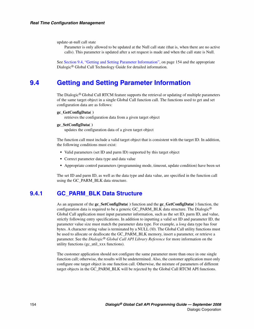
154 Dialogic® Global Call API Programming Guide — September 2008Dialogic Corporation
Real Time Configuration Management
update-at-null call state Parameter is only allowed to be updated at the Null call state (that is, when there are no active calls). This parameter is updated after a set request is made and when the call state is Null.
See Section 9.4, “Getting and Setting Parameter Information”, on page 154 and the appropriate Dialogic® Global Call Technology Guide for detailed information.
9.4 Getting and Setting Parameter Information
The Dialogic® Global Call RTCM feature supports the retrieval or updating of multiple parameters of the same target object in a single Global Call function call. The functions used to get and set configuration data are as follows:
gc_GetConfigData( ) retrieves the configuration data from a given target object
gc_SetConfigData( ) updates the configuration data of a given target object
The function call must include a valid target object that is consistent with the target ID. In addition, the following conditions must exist:
• Valid parameters (set ID and parm ID) supported by this target object
• Correct parameter data type and data value
• Appropriate control parameters (programming mode, timeout, update condition) have been set
The set ID and parm ID, as well as the data type and data value, are specified in the function call using the GC_PARM_BLK data structure.
9.4.1 GC_PARM_BLK Data Structure
As an argument of the gc_SetConfigData( ) function and the gc_GetConfigData( ) function, the configuration data is required to be a generic GC_PARM_BLK data structure. The Dialogic®
Global Call application must input parameter information, such as the set ID, parm ID, and value, strictly following entry specifications. In addition to inputting a valid set ID and parameter ID, the parameter value size must match the parameter data type. For example, a long data type has four bytes. A character string value is terminated by a NULL (\0). The Global Call utility functions must be used to allocate or deallocate the GC_PARM_BLK memory, insert a parameter, or retrieve a parameter. See the Dialogic® Global Call API Library Reference for more information on the utility functions (gc_util_xxx functions).
The customer application should not configure the same parameter more than once in one single function call; otherwise, the results will be undetermined. Also, the customer application must only configure one target object in one function call. Otherwise, the mixture of parameters of different target objects in the GC_PARM_BLK will be rejected by the Global Call RTCM API functions.

Dialogic® Global Call API Programming Guide — September 2008 155Dialogic Corporation
Real Time Configuration Management
9.4.2 Control Parameters
The Dialogic® Global Call RTCM API control parameters help to maintain the efficiency of the retrieve or update configuration process, and help to make sure that the application program is not blocked. The application can specify:
• the programming mode
• the timeout interval for completing the retrieval or update
• the update condition, that is, whether the update should occur either at the Null call state or immediately when updating the parameters of a target object with an active call. (This parameter does not apply to the gc_GetConfigData( ) function.)
9.4.2.1 Programming Mode
The customer application can specify whether to access configurations in the asynchronous mode or synchronous mode. The following paragraphs describe how the gc_GetConfigData( ) and gc_SetConfigData( ) functions operate in the asynchronous and synchronous programming modes:
gc_GetConfigData( ), Synchronous Mode Upon completion of the function call, the retrieved parameter data is still in the original GC_PARM_BLK data block after the gc_GetConfigData( ) function returns. The function’s return value, GC_SUCCESS, indicates that all requested parameters in a given target object have been successfully retrieved. Other return values indicate that at least one requested parameter in the target object failed to be retrieved due to an error. The gc_ErrorInfo( ) function is called immediately to obtain the last error and an additional message describing the parameter and the error (pointer to the additional message field). During the gc_GetConfigData( ) function call, once an error occurs, the Dialogic® Global Call API stops retrieving the remaining parameters and returns an error value to the application. If this function call is retrieving multiple parameters, the parameters before the error may have been retrieved while other parameters will not have had a chance to be retrieved.
gc_GetConfigData( ), Asynchronous Mode Upon completion of the function call, the Global Call application receives the GCEV_GETCONFIGDATA event if all requested parameters have been successfully retrieved. Otherwise, the Global Call application receives the GCEV_GETCONFIGDATA_FAIL event, which means at least one requested parameter of this request failed to be retrieved due to an error. The METAEVENT data structure associated with both events has a field evtdatap that points to a GC_RTCM_EVTDATA data structure. In GC_RTCM_EVTDATA, the retrieved _parmblkp field points to the retrieved parameter data. The error value and additional message describing the parameter and the error are also provided in the GC_RTCM_EVTDATA data structure.
Note: The gc_GetConfigData( ) function cannot be called in asynchronous mode for the following target types: GCTGT_GCLIB_SYSTEM, GCTGT_CCLIB_SYSTEM, GCTGT_PROTOCOL_SYSTEM, and GCTGT_FIRMWARE_SYSTEM. The function returns invalid target type. The gc_GetConfigData( ) function must be called in synchronous mode for these target types.

156 Dialogic® Global Call API Programming Guide — September 2008Dialogic Corporation
Real Time Configuration Management
gc_SetConfigData( ), Synchronous Mode Upon completion of the function call, the gc_SetConfigData( ) function returns a value of GC_SUCCESS to indicate that all requested parameters in a given target object have been successfully updated. Any other return value indicates that at least one requested parameter in a target object failed to be updated due to an error. The gc_ErrorInfo( ) function is called immediately to obtain the last error and an additional message describing the parameter and the error (pointer to the additional message field). During the gc_SetConfigData( ) function call, once an error occurs, Global Call stops updating the remaining parameters and returns an error value to the application. If this function call requires updating multiple parameters in a target object, the parameters before the error may have been updated while other parameters will not have a chance to be updated.
gc_SetConfigData( ), Asynchronous Mode The Global Call application receives the GCEV_SETCONFIGDATA event if all the requested parameters in a given target object are successfully updated. Otherwise, the Global Call application receives the GCEV_SETCONFIGDATA_FAIL event, which indicates that at least one requested parameter in the target object failed to update due to an error. The METAEVENT data structure, which is associated with both events, has a field, evtdatap, that points to a GC_RTCM_EVTDATA data structure. The GC_RTCM_EVTDATA data structure provides the error value and additional message describing the parameter and the error.
Note: When using E1, T1, and ISDN technologies, the gc_SetConfigData( ) function cannot be called in asynchronous mode for the following target types: GCTGT_GCLIB_SYSTEM, GCTGT_CCLIB_SYSTEM, GCTGT_PROTOCOL_SYSTEM, and GCTGT_FIRMWARE_SYSTEM. The function returns invalid target type. The gc_SetConfigData( ) function must be called in synchronous mode for these target types.
The original GC_PARM_BLK data block is not changed after the gc_SetConfigData( ) function returns.
9.4.2.2 Timeout Option
The following guidelines for using the timeout option apply:
• The customer application can specify the timeout for completing the parameter retrieval or update. The gc_GetConfigData( ) and gc_SetConfigData( ) functions support the timeout option only in synchronous mode. When a timeout occurs in the synchronous mode, the function returns an EGC_TIMEOUT error to the application. The timeout option is ignored if the function is executed in asynchronous mode.
• The function call is stopped immediately when a timeout occurs. When accessing multiple parameters in a single function call, some, but not all, parameters may have been retrieved or updated before the timeout.
• A timeout value selected to be less than or equal to zero indicates an infinite timeout. When the gc_SetConfigData( ) function has an infinite timeout set and is updated at the Null call state, this thread is blocked if the target object still has any active call. The customer application can avoid this situation by using the asynchronous mode or multi-threading technology.

Dialogic® Global Call API Programming Guide — September 2008 157Dialogic Corporation
Real Time Configuration Management
9.4.2.3 Update Condition
When using the gc_SetConfigData( ) function to update the parameters of a target object with an active call, the application can specify whether the update should occur either at the Null call state or immediately. If parameters are to be updated at the Null state, but the function requests to immediately update them while the target object has any active calls, the function returns an error to the application. If parameters are to be updated immediately, the function can update them immediately or at the Null state.
Table 17 describes the possible settings and resulting actions for the update condition as used by the gc_SetConfigData( ) function.
The gc_ResetLineDev( ) function is used to speed the update of the parameters that are waiting for the arrival of the Null state. For example, the customer application can call the gc_SetConfigData( ) function multiple times to request the parameters to be updated at the Null state. Instead of waiting for the Null state, the customer application can call the gc_ResetLineDev( ) function to reset the channel to the Null state and update all the parameters.
9.5 Querying Configuration Data
The gc_QueryConfigData( ) function provides limited query capability to obtain other configuration data based on known information. The search is limited to the given target object.
The main purpose of this function is to help the application find the protocol ID by name and the dynamic parameter ID by name. The source data and destination data point to a GC_PARM data structure.
Table 17. Update Condition Flag and Dialogic® Global Call Process
Update Condition Flag (Dialogic® Global Call
API APP)
Parameter Update Allowed in Target Object
Target Object StatusDialogic® Global Call
API Action
GCUPDATE_IMMEDIATE
Update immediately Active or no active call Update parameter
Update at Null stateNo active call Update parameter
Active call Return error
GCUPDATE_ATNULL
Update immediately
No active call Update parameter
Active call Postpone until no active call
Update at Null state
No active call Update parameter
Active call Postpone until no active call

158 Dialogic® Global Call API Programming Guide — September 2008Dialogic Corporation
Real Time Configuration Management
The query ID also defines the data type of the source data and destination data used by the gc_QueryConfigData( ) function. For example, GCQUERY_PARM_NAME_TO_ID implies the source data is a character string, and the destination data is a GC_PARM_ID data structure.
Note: The gc_QueryConfigData( ) function cannot be called in asynchronous mode for the following target types: GCTGT_GCLIB_SYSTEM, GCTGT_CCLIB_SYSTEM, GCTGT_PROTOCOL_SYSTEM, and GCTGT_FIRMWARE_SYSTEM. The function returns invalid target type. The gc_QueryConfigData( ) function must be called in synchronous mode for these target types.
9.6 Handling RTCM Errors
Configuration data for multiple parameters of a target object can be updated in a single Dialogic®
Global Call API function call. The function will abort on any single parameter retrieval failure. If the function returns a Global Call error, the application calls the gc_ErrorInfo( ) function immediately to obtain the last error code, error message, and additional message. An additional message identifies which parameter has an error. In the asynchronous mode, the application calls the gc_ResultInfo( ) function immediately to obtain the result value, error message, and additional message.
See the Dialogic® Global Call API Library Reference for Global Call RTCM error values and messages.
9.7 Configuration Procedure
The basic steps for using the Dialogic® Global Call RTCM feature are:
1. Check that the target object has been opened or loaded, and find the target object ID.
2. Find the parameter information (set ID, parm ID, and data type) related to the target object.
3. Find the parameter update condition or requirement. Understand the impact on the operation of itself or other target objects after change of parameters.
4. Select the appropriate programming mode, timeout, and update condition (if applicable) to allow Global Call to finish the request efficiently without blocking the application program.
Figure 35 illustrates the run-time configuration procedure.

Dialogic® Global Call API Programming Guide — September 2008 159Dialogic Corporation
Real Time Configuration Management
Figure 35. Run Time Configuration Procedure
9.8 Sample Scenarios Using the RTCM API Functions
This section shows the following examples in which the customer application uses the Dialogic® Global Call RTCM API functions to get or set the configuration of various target objects. The examples include:
• Getting or Setting GCLib Configuration in Synchronous Mode
• Getting or Setting CCLib Configuration in Synchronous Mode
• Getting or Setting Protocol Configuration in Synchronous Mode
• Getting or Setting Line Device Configuration in Synchronous Mode
• Setting Line Device Configuration in Asynchronous Mode
Application Global CallLibrary
gc_Start ()
gc_CCLibNameToID ()
Load CCLib
Get CCLib ID
Create Target Data for RetrievingCCLib Parameters
Get or Update Parameters of CCLib
Read Parameters from the Target Data Block for the gc_GetConfigData () Function
gc_GetConfigData () or gc_SetConfigData ()
gc_util_next_parm ()
Open a Time Slot and Load a Protocolgc_OpenEx ()
gc_QueryConfigData ()
gc_QueryConfigData ()
Find the Protocol ID
Find the Parm Info (Set ID, Parm ID,Data Type) by CDP Name
Create Target Data for Retrieving the Protocol Parameters
Get or Change the Parameter Values of a Protocol
Read Parameters from the Target Data Block for the gc_GetConfigData () Function
Create Target Data for Parameters of a Line Device
Get or Change Parameter Values of a Line Device
Read Parameters from the Target DataBlock for the gc_GetConfigData () Function
gc_util_insert_parm_ref () orgc_util_insert_parm_val ()
gc_GetConfigData () or gc_SetConfigData ()
gc_util_next_parm ()
gc_util_insert_parm_ref () orgc_util_insert_parm_val ()
gc_GetConfigData () or gc_SetConfigData ()
gc_util_next_parm ()
gc_util_insert_parm_ref () orgc_util_insert_parm_val ()
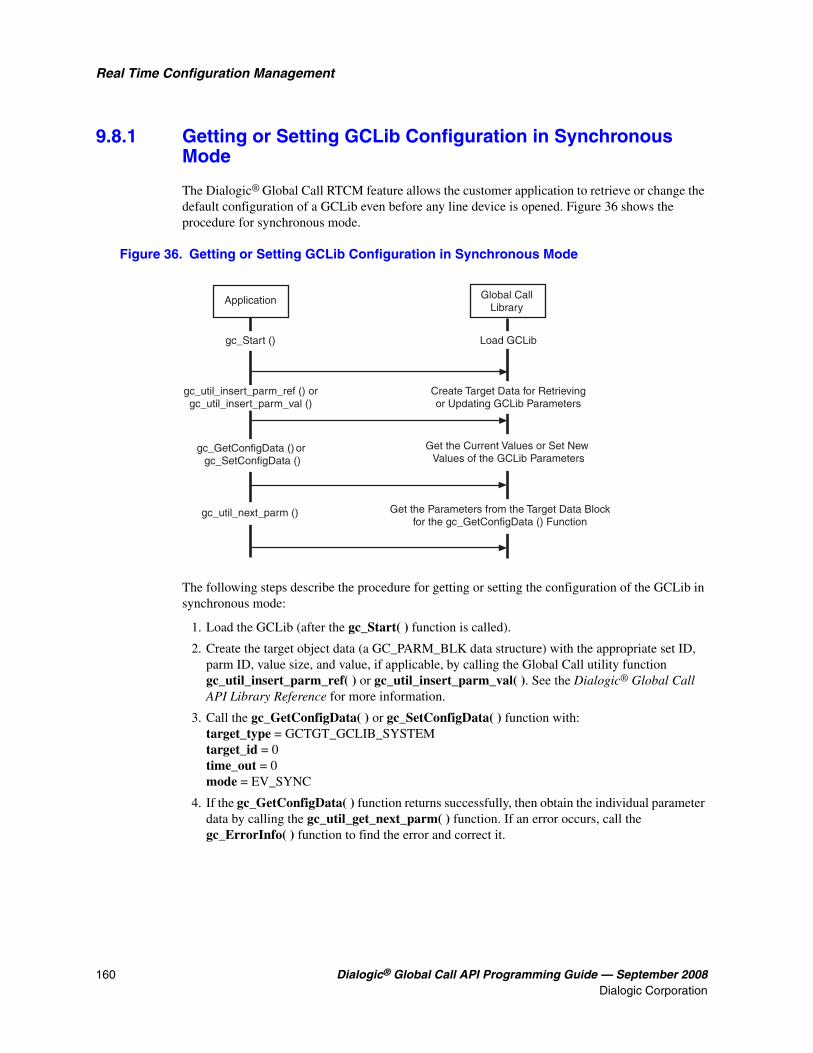
160 Dialogic® Global Call API Programming Guide — September 2008Dialogic Corporation
Real Time Configuration Management
9.8.1 Getting or Setting GCLib Configuration in Synchronous Mode
The Dialogic® Global Call RTCM feature allows the customer application to retrieve or change the default configuration of a GCLib even before any line device is opened. Figure 36 shows the procedure for synchronous mode.
Figure 36. Getting or Setting GCLib Configuration in Synchronous Mode
The following steps describe the procedure for getting or setting the configuration of the GCLib in synchronous mode:
1. Load the GCLib (after the gc_Start( ) function is called).
2. Create the target object data (a GC_PARM_BLK data structure) with the appropriate set ID, parm ID, value size, and value, if applicable, by calling the Global Call utility function gc_util_insert_parm_ref( ) or gc_util_insert_parm_val( ). See the Dialogic® Global Call API Library Reference for more information.
3. Call the gc_GetConfigData( ) or gc_SetConfigData( ) function with: target_type = GCTGT_GCLIB_SYSTEMtarget_id = 0time_out = 0mode = EV_SYNC
4. If the gc_GetConfigData( ) function returns successfully, then obtain the individual parameter data by calling the gc_util_get_next_parm( ) function. If an error occurs, call the gc_ErrorInfo( ) function to find the error and correct it.
Application Global CallLibrary
gc_Start ()
gc_util_insert_parm_ref () orgc_util_insert_parm_val ()
Load GCLib
Create Target Data for Retrievingor Updating GCLib Parameters
Get the Current Values or Set New Values of the GCLib Parameters
Get the Parameters from the Target Data Blockfor the gc_GetConfigData () Function
gc_GetConfigData () or gc_SetConfigData ()
gc_util_next_parm ()

Dialogic® Global Call API Programming Guide — September 2008 161Dialogic Corporation
Real Time Configuration Management
9.8.2 Getting or Setting CCLib Configuration in Synchronous Mode
The Dialogic® Global Call RTCM feature allows the customer application to retrieve or change the default configuration of a CCLib even before any line device is opened. Figure 37 shows the procedure for synchronous mode.
Figure 37. Getting or Setting CCLib Configuration in Synchronous Mode
The following steps describe the procedure for getting or setting the configuration of a CCLib in synchronous mode:
1. Load the call control library after the gc_Start( ) function is called.
2. Find the CCLib ID using its name by calling the gc_CCLibNameToID( ) function. If the application has doubt about the CCLib name, it can call the gc_GetCCLibStatusAll( ) function to verify whether the CCLib has been started.
3. Create the target object data (a GC_PARM_BLK data structure) with the appropriate set ID, parm ID, value size, and value, if applicable, by calling the Global Call utility function gc_util_insert_parm_ref( ) or gc_util_insert_parm_val( ). See the Dialogic® Global Call API Library Reference for more information.
4. Call the gc_GetConfigData( ) or gc_SetConfigData( ) function with:target_type = GCTGT_CCLIB_SYSTEMtarget_id = CCLib IDtime_out = 0mode = EV_SYNC
Application Global CallLibrary
gc_Start ()
gc_CCLibNameToID ()
gc_util_insert_parm_ref () orgc_util_insert_parm_val ()
Load CCLib
Get CCLib ID
Create Target Data for Retrievingor Upddating CCLib Parameters
Get the Current Values or Set New Values of the CCLib Parameters
Get the Parameters from the Target Data Blockfor the gc_GetConfigData () Function
gc_GetConfigData () or gc_SetConfigData ()
gc_util_next_parm ()

162 Dialogic® Global Call API Programming Guide — September 2008Dialogic Corporation
Real Time Configuration Management
5. If the gc_GetConfigData( ) function returns successfully, then obtain the individual parameter data by calling the gc_util_get_next_parm( ) function. If an error occurs, call the gc_ErrorInfo( ) function to find the error and correct it.
9.8.3 Getting or Setting Protocol Configuration in Synchronous Mode
The Dialogic® Global Call RTCM feature allows the customer application to retrieve or change the default configuration of a protocol. Figure 38 shows the procedure for the synchronous mode.
Figure 38. Getting or Setting Protocol Configuration in Synchronous Mode
The following steps describe the procedure for getting or setting the configuration of a protocol in the synchronous mode:
1. Load the protocol (after, in many cases, calling the gc_OpenEx( ) function for the first channel running the protocol).
2. Find the protocol ID by its name. Call the gc_QueryConfigData( ) function with:target type = GCTGT_GCLIB_SYSTEMtarget id = 0
Application Global CallLibrary
gc_OpenEx ()
gc_QueryConfigData ()
gc_QueryConfigData ()
Load a Protocol
Find the Protocol ID
Find the Parameter Information (Set ID, Parm ID, Data Type) by CDP Name
Create Target Data for Retrieving or Updating CDP Parameters
Get the Current Values or Set NewValues of the CDP Parameters
gc_util_insert_parm_ref () orgc_util_insert_parm_val ()
gc_GetConfigData () or gc_SetConfigData ()
Get the Parameters from the Target DataBlock for the gc_GetConfigData () Function
Open Other Channels with Updated Values of CDP Parameters
gc_util_next_parm ()
gc_OpenEx()

Dialogic® Global Call API Programming Guide — September 2008 163Dialogic Corporation
Real Time Configuration Management
query ID = GCQUERY_PROTOCOL_NAME_TO_IDsource data = protocol name
3. Find the CDP parameter ID by its name. Call the gc_QueryConfigData( ) function with: target type = GCTGT_PROTOCOL_SYSTEMtarget id = protocol IDquery ID = GCQUERY_PARM_NAME_TO_IDsource data = CDP name
4. Create the target object data (a GC_PARM_BLK data structure) with the appropriate set ID, parm ID, value size, and value by calling the Global Call utility function gc_util_insert_parm_ref( ) or gc_util_insert_parm_val( ). See the Dialogic® Global Call API Library Reference for more information.
5. Call the gc_GetConfigData( ) or gc_SetConfigData( ) function with:target_type = GCTGT_PROTOCOL_SYSTEM (for getting or setting the parameter on a system-wide basis, that is, for all channels) or GCTGT_PROTOCOL_CHAN (for getting or setting the parameter on an individual channel)target_id = protocol IDtime_out = 0mode = EV_SYNC
Note: If a CDP parameter value is changed, the change takes effect for newly opened devices only. It does not apply to devices that are already opened.
6. If the gc_GetConfigData( ) function returns successfully, then obtain the individual parameter data by calling the gc_util_get_next_parm( ) function. If an error occurs, call the gc_ErrorInfo( ) function to find the error and correct it.
7. Call the gc_OpenEx( ) function to open other channels with updated values of CDP parameters.
The following code shows a function that can be used to change a modifiable CDP parameter value for a channel:
// name = CDP parameter name// val = pointer to data// size = size of data
void ChangeChannelCDPParm( LINEDEV chan, char *name, void *val, int size ){ int id; /* protocol ID */ char prot_name[] = "pdk_ar_r2_io"; GC_PARM src, dest; GC_PARM_ID pair; GC_PARM_BLK *pblkp = NULL; GC_PARM_DATA *parm; long req_id;
// Get Protocol ID from name src.paddress = prot_name; gc_QueryConfigData( GCTGT_GCLIB_SYSTEM, 0, &src, GCQUERY_PROTOCOL_NAME_TO_ID, &dest ); id = dest.intvalue;
// Get CDP parameter IDs from name src.paddress = name; dest.pstruct = &pair; gc_QueryConfigData( GCTGT_PROTOCOL_SYSTEM, id, &src, GCQUERY_PARM_NAME_TO_ID, &dest );

164 Dialogic® Global Call API Programming Guide — September 2008Dialogic Corporation
Real Time Configuration Management
// Build GC_PARM_BLK and call SetConfigData to change CDP parameter gc_util_insert_parm_ref( &pblkp, pair.set_ID, pair.parm_ID, size, val ); gc_SetConfigData( GCTGT_PROTOCOL_CHAN, chan, pblkp, 0, GCUPDATE_ATNULL, &req_id, EV_SYNC ); /* Must be GCUPDATE_ATNULL for CDP parameters */ gc_util_delete_parm_blk( pblkp ); pblkp = NULL; /* strictly speaking, not necessary, but it is good practice to always set the parm block pointer to NULL when done with it */ }
9.8.4 Getting or Setting Line Device Configuration in Synchronous Mode
The Dialogic® Global Call RTCM feature allows the customer application to retrieve or change the default configuration of a line device in synchronous mode. Synchronous mode can be used effectively in any of the following cases:
• The request is to retrieve parameters.
• The request is to update parameters that are NOT call related.
• The request is to update parameters that are call related but there is no active call on the target object.
• The target type is neither GCTGT_FIRMWARE_CHAN nor GCTGT_FIRMWARE_NETIF (that is, the parameters are not maintained in the firmware).
Figure 39 shows the procedure for getting or setting line device configuration in synchronous mode.
Figure 39. Getting or Setting Line Device Configuration in Synchronous Mode
Application Global CallLibrary
gc_OpenEx ()
gc_QueryConfigData ()
Open a Line Device
Find the Set ID and Parm IDof the Parameters
Create Target Data for Retrieving or Updating Parameters of the Line Device
Get the Current Values or Set NewValues of the Parameters of the Line Device
gc_util_insert_parm_ref () orgc_util_insert_parm_val ()
gc_GetConfigData () or gc_SetConfigData ()
Get the Parameters from the Target DataBlock for the gc_GetConfigData () Function
gc_util_next_parm ()

Dialogic® Global Call API Programming Guide — September 2008 165Dialogic Corporation
Real Time Configuration Management
The following steps describe the procedure for getting or setting the configuration of a line device:
1. Open the line device (by calling the gc_OpenEx( ) function) and get the line device ID.
2. If the parameters of the line device are protocol CDP parameters, use an approach similar to getting the CDP parameter ID described in the “Getting or Setting Protocol Configuration in Synchronous Mode” section.
3. Create the target object data (a GC_PARM_BLK data structure) with the appropriate set ID, parm ID, value size, and value, if applicable, by calling the Global Call utility functions. See the Dialogic® Global Call API Library Reference for more information on the utility functions.
4. Call the gc_GetConfigData( ) or gc_SetConfigData( ) function with:target_type = GCTGT_CCLIB_NETIF, GCTGT_PROTOCOL_NETIF, GCTGT_CCLIB_CHAN, or GCTGT_PROTCOL_CHANtarget_id = Global Call line device IDtime_out > 0mode = EV_SYNCupdate condition = GCUPATE_IMMEDIATE (gc_SetConfigData( ) function only)
5. If the gc_GetConfigData( ) function returns successfully, obtain the individual parameter data by calling the gc_util_get_next_parm( ) function. If an error occurs, call the gc_ErrorInfo( ) function to find the error and then correct it.
9.8.5 Setting Line Device Configuration in Asynchronous Mode
The Dialogic® Global Call RTCM allows the customer application to retrieve or change the default configuration of a line device in asynchronous mode.
Asynchronous mode is generally suggested to be used in either of the following cases:
• The request is to update parameters that are call related and the channel is not at the NULL state.
• The target type is GCTGT_FIRMWARE_CHAN or GCTGT_FIRMWARE_NETIF (that is, the parameters are maintained in firmware).
Figure 40 shows the procedure for setting line device configuration in asynchronous mode.

166 Dialogic® Global Call API Programming Guide — September 2008Dialogic Corporation
Real Time Configuration Management
Figure 40. Setting Line Device Configuration in Asynchronous Mode
The procedure for setting the configuration of a line device in asynchronous mode is as follows:
1. The channel has an active call. Create the target object data (that is, a GC_PARM_BLK data structure) with the appropriate set ID, parm ID, value size, and value buffer by calling the Global Call utility functions. See the Dialogic® Global Call API Library Reference for more information.
2. Call the gc_SetConfigData( ) function with:target_type = GCTGT_CCLIB_NETIF, GCTGT_PROTOCOL_NETIF, GCTGT_FIRMWARE_NETIF, GCTGT_CCLIB_CHAN, GCTGT_PROTCOL_CHAN, or GCTGT_FIRMWARE_CHANtarget_id = Global Call line device IDtime_out = 0mode = EV_ASYNCupdate condition = GCUPATE_ATNULL
3. Call the gc_ResetLineDev( ) function to enforce the line to the NULL state.
4. If the gc_ResetLineDev( ) function is successful, a GCEV_RESETLINEDEV event is received. If the gc_SetConfigData( ) function is successful, a GCEV_SETCONFIGDATA event is received. If the GCEV_SETCONFIGDATA_FAIL event is received, call the gc_ResultInfo( ) function to find the error and correct it.
Application Global CallLibrary
GCEV_CONNECTED orGCEV_ANSWERED
Create Target Data for Parametersof the Line Device
Set the Parameters if this TimeslotTarget Object in Asynchronous Mode
Force the Line to the NULL State
gc_util_insert_parm_ref () orgc_util_insert_parm_val ()
gc_SetConfigData ()
Received RESETLINEDEV Event
gc_ResetLineDev ()
Received SETCONFIGDATA Event
GCEV_RESETLINEDEV
GCEV_SETCONFIGDATA
Received Connected orAnswered Event

Dialogic® Global Call API Programming Guide — September 2008 167Dialogic Corporation
Real Time Configuration Management
9.9 Dynamically Retrieving and Modifying Selected Protocol Parameters when Using Dialogic® DM3 Boards
The ability to dynamically retrieve or modify certain protocol-specific parameter values stored by the Dialogic® DM3 Board firmware is supported on the following boards:
• Dialogic® DM/V-A Media Boards
• Dialogic® DM/V-B Media Boards
This feature allows a user to dynamically (at run time) retrieve and/or modify the following parameter values:
• Protocol ID
• CAS signal definitions
• CDP variable values
• Line type (E1_CRC, D4, ESF) and coding (B8ZS, HDB3, AMI) for a trunk
• Protocol for a trunk
Some typical use cases for this feature are as follows:
• When a new system is configured and then provisioned by a new carrier, protocol parameters, such as wink settings, need to be tweaked before a call can be placed using the new switch. The provision of the API to perform these changes at run time alleviates the need to manually edit configuration files and subsequently re-download the firmware.
• When using ISDN protocols, the ability to dynamically determine the protocol running on a particular span is important in determining whether features such as Two-B Call Transfer (TBCT) or Overlapped Sending can be supported.
This feature is implemented using the Dialogic® Global Call RTCM facility, which uses the Global Call gc_GetConfigData( ), gc_SetConfigData( ), and gc_QueryConfigData( ) functions. Details on how to dynamically configure the parameter types mentioned above are provided in the following sections:
• Prerequisites for Feature Use
• Retrieving a Protocol ID
• Retrieving or Modifying CAS Signal Definitions
• Retrieving or Modifying CDP Variable Values
• Sample Code for Getting and Setting CAS Signal Definitions and CDP Variable Values
• Dynamically Configuring a Trunk
• Applicable Data Structures, Set IDs, and Parm IDs
• Restrictions and Limitations

168 Dialogic® Global Call API Programming Guide — September 2008Dialogic Corporation
Real Time Configuration Management
9.9.1 Prerequisites for Feature Use
Prerequisites are discussed in the following sections:
• Creating a dm3enum.cfg File
• Enabling Protocol Configuration
9.9.1.1 Creating a dm3enum.cfg File
Before this feature can be used, it must be enabled. To enable the feature, a configuration file named dm3enum.cfg must be created and stored in the Dialogic\cfg directory. The dm3enum.cfg file determines the boards on which this dynamic protocol configuration feature is to be enabled.
The syntax of the commands that can be included in a dm3enum.cfg file are:
board <n> Specifies a logical board (<n>) on which this feature is to be enabled.
board (startBd endBd) Specifies a range of boards on which this feature is to be enabled.
Notes: 1. The “board” command word can be abbreviated to “b”.
2. The startBd value must be less than the endBd value.
Some examples of commands that can be included in a dm3enum.cfg file are:
board 0 b 1 board (1 3) b (1 3)
The feature generates a number of log files in the Dialogic\log directory:
Dm3enumreate.log Log file for application that starts dynamic protocol configuration enablement
Protocol_enmurate_board_#.log Log file of actual dynamic protocol configuration enablement process for boards that use non-PDK protocols
Pdkenumerate.log_board# Log file of actual dynamic protocol configuration enablement process for boards that use PDK protocols
9.9.1.2 Enabling Protocol Configuration
To enable protocol configuration for PDK protocols, after running the pdkmanagerregsetup add command, run the following command:
pdkmanagerregsetup enumerate
Then,
• Download the board firmware.

Dialogic® Global Call API Programming Guide — September 2008 169Dialogic Corporation
Real Time Configuration Management
• Run the devmapdump utility to check that the protocol information has been loaded (search for CDP_ and CAS_ parameters). If this is not the case, run the dm3enumerate utility to load the protocol information manually after each firmware download.
To enable protocol configuration for non-PDK protocols, run the dm3enumerate utility to load protocol name information.
9.9.2 Retrieving a Protocol ID
DM3 protocol names have the format “lb#pv#:Variant_Name”, where:
• lb# is the logical board ID on a physical DM3 Board
• pv# is the protocol variant ID
Some examples are:
• “lb1pv1:pdk_us_mf_io” - A PDK protocol that is the first protocol variant on logical board 1
• “lb2pv1:isdn_net5” - An ISDN Net5 protocol that is the first protocol variant on logical board 2
• “lb0pv5:analog_loop_fxs”- An analog protocol that is the fifth protocol variant on logical board 0
Note: All characters in protocol names are lowercase.
The protocol ID is assigned by Global Call, and the user must obtain the protocol ID prior to accessing any protocol-related data.
The protocol name and ID for a DM3 Board can be obtained by calling the gc_GetConfigData( ) function on an opened time slot device handle with the following parameter values:
• target_type = GCTGT_GCLIB_CHAN
• target_id = the line device handle
• target_datap = GC_PARM_BLKP parameter pointer, as constructed by the utility function gc_util_insert_parm_val( ) for protocol ID and gc_util_insert_parm_ref( ) for protocol name
• time_out = time interval (in seconds) during which data must be retrieved. If the interval is exceeded, the retrieve request is ignored. This parameter is supported in synchronous mode only, and it is ignored when set to 0.
• request_idp = pointer to the location for storing the request ID
• mode = EV_ASYNC for asynchronous execution or EV_SYNC for synchronous execution. EV_SYNC mode is recommended.
Note: Only time slot objects support the retrieval of the protocol ID and name.
See Section 9.9.5, “Sample Code for Getting and Setting CAS Signal Definitions and CDP Variable Values”, on page 173, specifically the ObtainProtocolIDAndName( ) function, for example code that demonstrates how to retrieve the protocol ID and name.

170 Dialogic® Global Call API Programming Guide — September 2008Dialogic Corporation
Real Time Configuration Management
If the protocol name is known, the protocol ID can be obtained by calling the gc_QueryConfigData( ) function with the following parameter values:
• target_type = GCTGT_GCLIB_SYSTEM
• target_id = GC_LIB
• source_datap = GC_PARM parameter pointer for storing the protocol name (input)
• query_id = Query ID, in this case, GCQUERY_PROTOCOL_NAME_TO_ID
• response_datap = GC_PARM parameter pointer for storing the protocol ID (output)
9.9.3 Retrieving or Modifying CAS Signal Definitions
This feature enables the user to dynamically retrieve or modify CAS signal definitions. Before the CAS signal definition can be retrieved or modified, the {set ID:parm ID} pair that identifies the signal in the firmware must be retrieved. The datatype of the corresponding parameter value must also be retrieved. The following sections describe the operations relating to CAS signal definitions that can be performed:
• Obtaining the {Set ID:Parm ID} Pair for a CAS Signal
• Retrieving a CAS Signal Definition
• Setting a CAS Signal Definition
9.9.3.1 Obtaining the {Set ID:Parm ID} Pair for a CAS Signal
Each CAS parameter in a DM3 PDK protocol has a unique {set ID:parm ID} pair, in which the set ID represents the component that contains the parameter and parm ID represents an internal ID within that component. The set ID is one of a predefined set of values in the dm3cc_parm.h file, and the parm ID is assigned by the DM3 firmware at download time. For example, the CAS_ANSWER parameter (which defines a CAS signal) is contained in the CAS component identified by the PRSET_CAS_SIGNAL set ID with the parm ID being assigned internally by the firmware.
Before dynamically retrieving or modifying the value of a CAS parameter in the DM3 firmware, the user must call the gc_QueryConfigData( ) function to obtain the {set ID:parm ID} pair of the CAS parameter using the parameter name obtained from the CDP file.
The gc_QueryConfigData( ) function is called with the following parameter values:
• target_type = GCTGT_PROTOCOL_SYSTEM
• target_id = PDK Protocol ID
• source_datap = GC_PARM parameter pointer for storing input CAS parameter name
• query_id = Query ID, in this case, GCQUERY_PARM_NAME_TO_ID
• response_datap = GC_PARM parameter pointer for storing output {set ID:parm ID} and value type

Dialogic® Global Call API Programming Guide — September 2008 171Dialogic Corporation
Real Time Configuration Management
See Section 9.9.5, “Sample Code for Getting and Setting CAS Signal Definitions and CDP Variable Values”, on page 173, specifically the QueryParmID( ) function, for example code that demonstrates how to retrieve the {set ID:parm ID} pair for a CAS signal.
Note: Obtaining the {set ID:parm ID} pair is a prerequisite to retrieving the definition of a CAS signal or redefining a CAS signal.
9.9.3.2 Retrieving a CAS Signal Definition
The gc_GetConfigData( ) function can be used to retrieve the value of CAS parameters in the DM3 firmware. Function parameter values to use in this context are:
• target_type = GCTGT_PROTOCOL_SYSTEM
• target_id = PDK Protocol ID
• target_datap = GC_PARM_BLKP parameter pointer, as constructed by the gc_util_insert_parm_ref( ) utility function for CAS signal
• time_out = time interval (in seconds) during which the parameter value must be retrieved. If the interval is exceeded, the retrieve request is ignored. This parameter is supported in synchronous mode only, and it is ignored when set to 0.
• request_idp = pointer to the location for storing the request ID, output from Global Call
• mode = EV_ASYNC for asynchronous execution or EV_SYNC for synchronous execution. EV_ASYNC mode is recommended.
See Section 9.9.5, “Sample Code for Getting and Setting CAS Signal Definitions and CDP Variable Values”, on page 173, specifically the GetCASSignalDef( ) function, for example code that demonstrates how to retrieve the definition of a CAS signal, in this case the CAS_WINKREV signal.
9.9.3.3 Setting a CAS Signal Definition
The gc_SetConfigData( ) function with the following parameter values can be used to set a new definition for a CAS signal in the DM3 firmware:
• target_type = GCTGT_PROTOCOL_SYSTEM
• target_id = PDK Protocol ID
• target_datap = GC_PARM_BLKP parameter pointer, as constructed by the utility function gc_util_insert_parm_ref( ) for the CAS signal
• time_out = time interval (in seconds) during which the parameter value must be updated. If the interval is exceeded, the update request is ignored. This parameter is supported in synchronous mode only, and it is ignored when set to 0.
• update_cond = ignored for DM3 PDK protocols
• request_idp = pointer to the location for storing the request ID, output from Global Call
• mode = EV_ASYNC for asynchronous execution or EV_SYNC for synchronous execution. EV_ASYNC mode is recommended.
See Section 9.9.5, “Sample Code for Getting and Setting CAS Signal Definitions and CDP Variable Values”, on page 173, specifically the SetCASSignalDef( ) function, for example code

172 Dialogic® Global Call API Programming Guide — September 2008Dialogic Corporation
Real Time Configuration Management
that demonstrates how to change the definition of a CAS signal, in this case the CAS_WINKREV signal.
9.9.4 Retrieving or Modifying CDP Variable Values
This feature enables the user to dynamically retrieve or modify parameter values defined in DM3 PDK protocol country dependent parameter (CDP) files. Before the CDP variable value can be retrieved or modified, the {set ID:parm ID} pair that identifies the CDP variable in the firmware must be retrieved. The datatype of the corresponding CDP variable value must also be retrieved. The following sections describe the operations relating to CDP variable values that can be performed:
• Obtaining the {Set ID:Parm ID} Pair for a CDP Variable
• Getting the Current Values of Multiple CDP Variables
• Setting New Values for Multiple CDP Variables
9.9.4.1 Obtaining the {Set ID:Parm ID} Pair for a CDP Variable
Each CDP variable in a DM3 PDK protocol has a unique {set ID:parm ID} pair, in which the set ID represents the component that contains the parameter and parm ID represents an internal ID within that component. The set ID is one of a predefined set of values in the dm3cc_parm.h file, and the parm ID is assigned by the DM3 firmware at download time.
Before dynamically retrieving or modifying the value of a CDP variable in the DM3 firmware, the user must call the gc_QueryConfigData( ) function to obtain the {set ID:parm ID} pair of the CDP variable using the parameter name obtained from the CDP file.
The gc_QueryConfigData( ) function is called with the following parameter values:
• target_type = GCTGT_PROTOCOL_SYSTEM
• target_id = PDK Protocol ID
• source_datap = GC_PARM parameter pointer for storing the input CDP variable name
• query_id = Query ID, in this case, GCQUERY_PARM_NAME_TO_ID
• response_datap = GC_PARM parameter pointer for storing the output {set ID:parm ID} and value type
Note: Obtaining the {set ID:parm ID} pair is a prerequisite to retrieving or changing the value of a CDP variable.
See Section 9.9.5, “Sample Code for Getting and Setting CAS Signal Definitions and CDP Variable Values”, on page 173, specifically the QueryParmID( ) function, for example code that demonstrates how to retrieve the {set ID:parm ID} pair for a CDP variable.
9.9.4.2 Getting the Current Values of Multiple CDP Variables
The gc_GetConfigData( ) function can be used to retrieve the value of a CDP variable in the DM3 firmware. Function parameter values to use in this context are:
• target_type = GCTGT_PROTOCOL_SYSTEM

Dialogic® Global Call API Programming Guide — September 2008 173Dialogic Corporation
Real Time Configuration Management
• target_id = PDK Protocol ID
• target_datap = GC_PARM_BLKP parameter pointer, as constructed by the utility function gc_util_insert_parm_val( ) for CDP integer value and gc_util_insert_parm_ref( ) for CDP string value
• time_out = time interval (in seconds) during which the parameter value must be retrieved. If the interval is exceeded, the retrieve request is ignored. This parameter is supported in synchronous mode only, and it is ignored when set to 0.
• request_idp = pointer to the location for storing the request ID, output from Global Call
• mode = EV_ASYNC for asynchronous execution or EV_SYNC for synchronous execution. EV_ASYNC mode is recommended.
See Section 9.9.5, “Sample Code for Getting and Setting CAS Signal Definitions and CDP Variable Values”, on page 173, specifically the GetCDPVarParms( ) function, for example code that demonstrates how to get the current values of multiple CDP variables.
9.9.4.3 Setting New Values for Multiple CDP Variables
The gc_SetConfigData( ) function can be used to set new values for multiple CDP variables in the DM3 firmware. Function parameter values to use in this context are:
• target_type = GCTGT_PROTOCOL_SYSTEM
• target_id = PDK Protocol ID
• target_datap = GC_PARM_BLKP parameter pointer, as constructed by the utility function gc_util_insert_parm_val( ) for the CDP integer value and gc_util_insert_parm_ref( ) for the CDP string value
• time_out = time interval (in seconds) during which the parameter value must be updated. If the interval is exceeded, the update request is ignored. This parameter is supported in synchronous mode only, and it is ignored when set to 0.
• update_cond = ignored for DM3 PDK protocol parameters
• request_idp = pointer to the location for storing the request ID, output from Global Call
• mode = EV_ASYNC for asynchronous execution or EV_SYNC for synchronous execution. EV_ASYNC mode is recommended.
See Section 9.9.5, “Sample Code for Getting and Setting CAS Signal Definitions and CDP Variable Values”, on page 173, specifically the SetCDPVarParms( ) function, for example code that demonstrates how to set new values of multiple CDP variables.
9.9.5 Sample Code for Getting and Setting CAS Signal Definitions and CDP Variable Values
/* Dialogic Header Files */#include <gcip.h>#include <gclib.h>#include <gcisdn.h>#include <srllib.h>#include <dm3cc_parm.h>

174 Dialogic® Global Call API Programming Guide — September 2008Dialogic Corporation
Real Time Configuration Management
int ObtainProtocolIDAndName(LINEDEV a_GCLineDevH, char *a_pProtName, long *a_pProtID){ GC_PARM_BLK * t_pParmBlk = NULL; GC_PARM_DATA * t_pParmData = NULL; char * t_ProtName[20]; long t_RequestID = 0; int t_result; /* Reserve the space for protocol ID */ *a_pProtID = 0; gc_util_insert_parm_val(&t_pParmBlk, GCSET_PROTOCOL, GCPARM_PROTOCOL_ID, sizeof(long), *a_pProtID); /* Reserve the space for protocol Name */ gc_util_insert_parm_ref(&t_pParmBlk, GCSET_PROTOCOL, GCPARM_PROTOCOL_NAME, sizeof(t_ProtName), t_ProtName); /* Since the protocol information has already been stored in GC library during gc_OpenEx(), it is recommended to call gc_GetConfigData() in SYNC mode */ t_result = gc_GetConfigData(GCTGT_GCLIB_CHAN, a_GCLineDevH, t_pParmBlk, 0, & t_RequestID, EV_SYNC); if (t_result) { /* Process the error */ gc_util_delete_parm_blk(t_pParmBlk); return t_result; } /* Obtain the protocol ID */ t_pParmData = gc_util_find_parm(t_pParmBlk, GCSET_PROTOCOL, GCPARM_PROTOCOL_ID); if (NULL != t_pParmData) { memcpy(a_pProtID, t_pParmData->value_buf, t_pParmData->value_size); } /* Obtain the protocol Name */ t_pParmData = gc_util_find_parm(t_pParmBlk, GCSET_PROTOCOL, GCPARM_PROTOCOL_NAME); if (NULL != t_pParmData) { strcpy(a_pProtName, (const char*)t_pParmData->value_buf); } printf("ObtainProtocolIDAndName(linedev:%d, protocol_id:%d, protocol_name:%s)", a_GCLineDevH, *a_pProtID, a_pProtName); gc_util_delete_parm_blk(t_pParmBlk); return t_result;}
int QueryParmID(long a_PDKProtocolID, char *a_pParmName, unsigned short * a_pSetID, unsigned short * a_pParmID, unsigned char * a_pValType){ GC_PARM t_SourceData; GC_PARM t_RespData; GC_PARM_ID t_ParmIDBlk; int t_result = 0; /* Pass the CDP name, which is defined in CDP file, e.g., "CAS_WINKRCV" or "CDP_ANI_ENABLED" in pdk_us_mf_io.cdp */ t_SourceData.paddress = a_pParmName; memset(&t_ParmIDBlk, '0', sizeof(GC_PARM_ID)); t_RespData.pstruct = & t_ParmIDBlk; t_result = gc_QueryConfigData(GCTGT_PROTOCOL_SYSTEM, a_PDKProtocolID, &t_SourceData, GCQUERY_PARM_NAME_TO_ID, &t_RespData); if (t_result) { /* Process the error */ *a_pSetID = 0; *a_pParmID = 0; *a_pValType = 0; printf("gc_QueryConfigData(parm:%s) failed on protocol:%d", a_pParmName, a_PDKProtocolID);

Dialogic® Global Call API Programming Guide — September 2008 175Dialogic Corporation
Real Time Configuration Management
} else { *a_pSetID = t_ParmIDBlk.set_ID; *a_pParmID = t_ParmIDBlk.parm_ID; *a_pValType = t_ParmIDBlk.value_type; printf("gc_QueryConfigData(parm:%s) succeed with {setID:0x%x, parmID:0x%x, valType:%d} on protocol:%d", a_pParmName, *a_pSetID, *a_pParmID, *a_pValType, a_PDKProtocolID); } return t_result;}
int SetCASSignalDef(long a_PDKProtocolID){ GC_PARM_BLK * t_pParmBlk = NULL; unsigned short t_SetID; unsigned short t_ParmID; unsigned char t_ValType; long t_RequestID = 0; int t_result = 0; GC_CASPROT_TRANS t_CasTrans; GC_CASPROT_PULSE t_CasPulse = {"00xx", "11xx", 50, 62, 0, 80, 20, 250, 300}; GC_CASPROT_TRAIN t_CasTrain; /* Find the {setID, parmID, DataType} of CAS_WINKRCV for pdk_us_mf_io */ t_result = QueryParmID(a_PDKProtocolID, "CAS_WINKRCV", &t_SetID, &t_ParmID, &t_ValType); if (t_result) { /* Process the error */ return t_result; } /* Insert new definition for CAS signals, dependent on the signal type */ switch (t_ValType) { case GC_VALUE_CAS_TRANS: gc_util_insert_parm_ref(&t_pParmBlk, t_SetID, t_ParmID, sizeof(GC_CASPROT_TRANS), &t_CasTrans); break; case GC_VALUE_CAS_PULSE: gc_util_insert_parm_ref(&t_pParmBlk, t_SetID, t_ParmID, sizeof(GC_CASPROT_PULSE), &t_CasPulse); break; case GC_VALUE_CAS_TRAIN: gc_util_insert_parm_ref(&t_pParmBlk, t_SetID, t_ParmID, sizeof(GC_CASPROT_TRAIN), &t_CasTrain); break; default: /* Process the error here */ return -1; break; } /* Set the CAS_WINKRCV with new value */ t_result = gc_SetConfigData(GCTGT_PROTOCOL_SYSTEM, a_PDKProtocolID, t_pParmBlk, 0, GCUPDATE_IMMEDIATE, &t_RequestID, EV_ASYNC); if (t_result) { /* Process the error */ gc_util_delete_parm_blk(t_pParmBlk); return t_result; } gc_util_delete_parm_blk(t_pParmBlk); return t_result;}

176 Dialogic® Global Call API Programming Guide — September 2008Dialogic Corporation
Real Time Configuration Management
int GetCASSignalDef(long a_PDKProtocolID){ GC_PARM_BLK * t_pParmBlk = NULL; unsigned short t_SetID; unsigned short t_ParmID; unsigned char t_ValType; long t_RequestID = 0; int t_result = 0; GC_CASPROT_TRANS t_CasTrans; GC_CASPROT_PULSE t_CasPulse; GC_CASPROT_TRAIN t_CasTrain; /* Find the {setID, parmID, dataType} of CAS_WINKRCV for pdk_us_mf_io */ t_result = QueryParmID(a_PDKProtocolID, "CAS_WINKRCV", &t_SetID, &t_ParmID, &t_ValType); if (t_result) { /* Process the error */ return t_result; } /* Insert memory space for storing definition for CAS signals, dependent on the signal type */ switch (t_ValType) { case GC_VALUE_CAS_TRANS: memset( &t_CasPulse, 0, sizeof(GC_CASPROT_TRANS) ); gc_util_insert_parm_ref(&t_pParmBlk, t_SetID, t_ParmID, sizeof(GC_CASPROT_TRANS), &t_CasTrans); break; case GC_VALUE_CAS_PULSE: memset( &t_CasPulse, 0, sizeof(GC_CASPROT_PULSE) ); gc_util_insert_parm_ref(&t_pParmBlk, t_SetID, t_ParmID, sizeof(GC_CASPROT_PULSE), &t_CasPulse); break; case GC_VALUE_CAS_TRAIN: memset( &t_CasPulse, 0, sizeof(GC_CASPROT_TRAIN) ); gc_util_insert_parm_ref(&t_pParmBlk, t_SetID, t_ParmID, sizeof(GC_CASPROT_TRAIN), &t_CasTrain); break; default: /* Process the error here */ return -1; break; } /* Get the CAS_WINKRCV with new value */ t_result = gc_GetConfigData(GCTGT_PROTOCOL_SYSTEM, a_PDKProtocolID, t_pParmBlk, 0, &t_RequestID, EV_ASYNC); if (t_result) { /* Process the error */ gc_util_delete_parm_blk(t_pParmBlk); return t_result; } gc_util_delete_parm_blk(t_pParmBlk); return t_result;}
typedef struct { char name[50]; int type; void * valuep;} CDP_PARM;
int GetCDPVarParms(long a_PDKProtocolID, int a_NumParms, CDP_PARM * a_CDPVarParms, long * a_pRequestID){ GC_PARM_BLK * t_pParmBlk = NULL; unsigned short t_SetID; unsigned short t_ParmID;

Dialogic® Global Call API Programming Guide — September 2008 177Dialogic Corporation
Real Time Configuration Management
unsigned char t_ValType = 0; int t_result = 0; int index1 = 0; if (!a_PDKProtocolID) { /* Process the error */ return -1; } if (!a_CDPVarParms) { /* Process the error */ return -1; } /* Support retrieving multiple CDP variables in a single gc_GetConfigData() function call */ for (index1 = 0; index1 < a_NumParms; index1 ++) { /* Find the {setID, parmID, valueType} of each CDP variable by its name: e.g., "CDP_ANI_ENABLED" in pdk_ar_r2_io.cdp */ t_result = QueryParmID(a_PDKProtocolID, a_CDPVarParms[index1].name, &t_SetID, &t_ParmID, &t_ValType); if (t_result) { /* Process the error */ gc_util_delete_parm_blk(t_pParmBlk); return t_result; } if (t_SetID != PRSET_TSC_VARIABLE) { /* Not a CDP variable parameter */ gc_util_delete_parm_blk(t_pParmBlk); return -1; } /* Insert new definition for CDP variable signals, dependent on the value data type */ switch (t_ValType) { case GC_VALUE_SHORT: gc_util_insert_parm_val(&t_pParmBlk, t_SetID, t_ParmID, sizeof(unsigned short), 0); break; case GC_VALUE_STRING: gc_util_insert_parm_ref(&t_pParmBlk, t_SetID, t_ParmID, 30, ""); break; case GC_VALUE_ULONG: gc_util_insert_parm_val(&t_pParmBlk, t_SetID, t_ParmID, sizeof(unsigned long), 0); break; case GC_VALUE_UCHAR: gc_util_insert_parm_val(&t_pParmBlk, t_SetID, t_ParmID, sizeof(unsigned char), 0); break; default: /* Process the error here */ printf("!!!!Invalid value type for protocolID:%d to CDP variable(name:%s, set_id:0x%x, parm_id:0x%x, valtype:%d)", a_PDKProtocolID, a_CDPVarParms[index1].name, t_SetID, t_ParmID, t_ValType); gc_util_delete_parm_blk(t_pParmBlk); return -1; break; } } /* Get the values of multiple CDP variables */ *a_pRequestID = 0; t_result = gc_GetConfigData(GCTGT_PROTOCOL_SYSTEM, a_PDKProtocolID, t_pParmBlk, 0, a_pRequestID, EV_ASYNC); if (t_result)

178 Dialogic® Global Call API Programming Guide — September 2008Dialogic Corporation
Real Time Configuration Management
{ /* Process the error */ printf("gc_GetConfigData(protocol_id:%d) failed on setting CDP parameters()", a_PDKProtocolID); *a_pRequestID = 0; } else { printf("gc_GetConfigData(protocol_id:%d, req_id:0x%x) succeed on setting CDP parameters", a_PDKProtocolID, *a_pRequestID); } gc_util_delete_parm_blk(t_pParmBlk); return t_result;}
int SetCDPVarParms(long a_PDKProtocolID, int a_NumParms, CDP_PARM * a_CDPVarParms, long * a_pRequestID){ GC_PARM_BLK * t_pParmBlk = NULL; unsigned short t_SetID; unsigned short t_ParmID; unsigned char t_ValType = 0; int t_result = 0; int t_IntVal = 0; unsigned long t_ULongVal = 0; unsigned char t_UCharVal = 0; unsigned char t_StrSize = 0; int index1 = 0; if (!a_PDKProtocolID) { /* Process the error */ return -1; } if (!a_CDPVarParms) { /* Process the error */ return -1; } /* Support setting multiple CDP variables in a single gc_SetConfigData() function call */ for (index1 = 0; index1 < a_NumParms; index1 ++) { /* Find the {setID, parmID, valueType} of each CDP variable by its name: e.g., "CDP_ANI_ENABLED" in pdk_ar_r2_io.cdp */ t_result = QueryParmID(a_PDKProtocolID, a_CDPVarParms[index1].name, &t_SetID, &t_ParmID, &t_ValType); if (t_result) { /* Process the error */ gc_util_delete_parm_blk(t_pParmBlk); return t_result; } if (t_SetID != PRSET_TSC_VARIABLE) { /* Not a CDP variable parameter */ gc_util_delete_parm_blk(t_pParmBlk); return -1; } /* Insert new definition for CDP variable signals, dependent on the value data type */ switch (t_ValType) { case GC_VALUE_INT: t_IntVal = *((int*)a_CDPVarParms[index1].valuep); gc_util_insert_parm_val(&t_pParmBlk, t_SetID, t_ParmID, sizeof(int), t_IntVal); printf("Set Integer Value:%d (0x%x) to parmID:0x%x", t_IntVal, t_IntVal, t_ParmID);

Dialogic® Global Call API Programming Guide — September 2008 179Dialogic Corporation
Real Time Configuration Management
break; case GC_VALUE_STRING: t_StrSize = strlen((char *)a_CDPVarParms[index1].valuep) + 1; gc_util_insert_parm_ref(&t_pParmBlk, t_SetID, t_ParmID, t_StrSize, (char *) a_CDPVarParms[index1].valuep); printf("Set String Value:%s to parmID:0x%x", (char *) a_CDPVarParms[index1].valuep, t_ParmID); break; case GC_VALUE_ULONG: t_ULongVal = *((unsigned long *)a_CDPVarParms[index1].valuep); gc_util_insert_parm_val(&t_pParmBlk, t_SetID, t_ParmID, sizeof(unsigned long), t_ULongVal); printf("Set Long Value:%d (0x%x) to parmID:0x%x", t_ULongVal, t_ULongVal, t_ParmID); break; case GC_VALUE_UCHAR: t_UCharVal = *((unsigned char *)a_CDPVarParms[index1].valuep); gc_util_insert_parm_val(&t_pParmBlk, t_SetID, t_ParmID, sizeof(unsigned char), t_UCharVal); printf("Set Char Value:%d(0x%x) to parmID:0x%x", t_UCharVal, t_UCharVal, t_ParmID); break; default: /* Process the error here */ printf("!!!!Invalid value type for protocolID:%d to CDP variable(name:%s, set_id:0x%x, parm_id:0x%x, valtype:%d)", a_PDKProtocolID, a_CDPVarParms[index1].name, t_SetID, t_ParmID, t_ValType); gc_util_delete_parm_blk(t_pParmBlk); return -1; break; } } /* Set the CDP parameters with new values */ *a_pRequestID = 0; t_result = gc_SetConfigData(GCTGT_PROTOCOL_SYSTEM, a_PDKProtocolID, t_pParmBlk, 0, GCUPDATE_IMMEDIATE, a_pRequestID, EV_ASYNC); if (t_result) { /* Process the error */ printf("gc_SetConfigData(protocol_id:%d) failed on setting CDP parameters()", a_PDKProtocolID); *a_pRequestID = 0; } else { printf("gc_SetConfigData(protocol_id:%d, req_id:0x%x) succeed on setting CDP parameters", a_PDKProtocolID, *a_pRequestID); } gc_util_delete_parm_blk(t_pParmBlk); return t_result;}
int ProcessRTCMEvent(unsigned long a_GCEvent, unsigned long a_ReqID, GC_PARM_BLK * a_pParmBlk){ GC_CASPROT_TRANS * t_pCasTrans = NULL; GC_CASPROT_PULSE * t_pCasPulse = NULL; GC_CASPROT_TRAIN * t_pCasTrain = NULL; unsigned char t_UCharVal = 0; unsigned short t_UShortVal = 0; unsigned long t_ULongVal = 0; char * t_StringVal = NULL; int t_StrLen = 0; /* Obtain the first parameter */ GC_PARM_DATA * t_pParmData = gc_util_next_parm(a_pParmBlk, NULL);

180 Dialogic® Global Call API Programming Guide — September 2008Dialogic Corporation
Real Time Configuration Management
while (t_pParmData) { if (t_pParmData->set_ID == PRSET_CAS_SIGNAL) { /* This is a CAS signal */ if (t_pParmData->value_size == sizeof(GC_CASPROT_TRANS) ) { t_pCasTrans = (GC_CASPROT_TRANS *) &t_pParmData->value_buf; printf("Obtain CAS Trans signal definition on parmID:0x%x (%s, %s, %d, %d, %d, %d)", t_pParmData->parm_ID, t_pCasTrans->PreTransCode, t_pCasTrans->PostTransCode, t_pCasTrans->PreTransInterval, t_pCasTrans->PostTransInterval, t_pCasTrans->PreTransIntervalNom, t_pCasTrans->PostTransIntervalNom); } else if (t_pParmData->value_size == sizeof(GC_CASPROT_PULSE) ) { t_pCasPulse = (GC_CASPROT_PULSE *) &t_pParmData->value_buf; printf("Obtain CAS Pulse signal definition on parmID:0x%x (%s, %s, %d, %d, %d, %d, %d, %d, %d) ", t_pParmData->parm_ID, t_pCasPulse->OffPulseCode, t_pCasPulse->OnPulseCode, t_pCasPulse->PrePulseInterval, t_pCasPulse->PostPulseInterval, t_pCasPulse->PrePulseIntervalNom, t_pCasPulse->PostPulseIntervalNom, t_pCasPulse->PulseIntervalMin, t_pCasPulse->PulseIntervalNom, t_pCasPulse->PulseIntervalMax); } else if (t_pParmData->value_size == sizeof(GC_CASPROT_TRAIN) ) { t_pCasTrain = (GC_CASPROT_TRAIN *) &t_pParmData->value_buf; printf("Obtain CAS Train signal definition on parmID:0x%x (%s, %s, %d, %d, %d, %d, %d, %d, %d) ", t_pParmData->parm_ID, t_pCasTrain->OffPulseCode, t_pCasTrain->OnPulseCode, t_pCasTrain->PreTrainInterval, t_pCasTrain->PostTrainInterval, t_pCasTrain->PreTrainIntervalNom, t_pCasTrain->PostTrainIntervalNom, t_pCasTrain->PulseIntervalMin, t_pCasTrain->PulseIntervalNom, t_pCasTrain->PulseIntervalMax); } else { printf("Error! Incorrect value_size =%d for {setID:0x%x, parmID:0x%x}", t_pParmData->value_size, t_pParmData->set_ID, t_pParmData->parm_ID); } } else if (t_pParmData->set_ID == PRSET_TSC_VARIABLE) { /* This is a TSC Variable */ switch (t_pParmData->value_size) { case 1: /* Unisgned char data */ memcpy(&t_UCharVal, &t_pParmData->value_buf,t_pParmData->value_size); printf("Obtain TSC unsigned char value:%d(0x%x) of parmID:0x%x\n", t_UCharVal, t_UCharVal, t_pParmData->parm_ID); break; case 2: /* Unisgned short data */ memcpy(&t_UShortVal, &t_pParmData->value_buf,t_pParmData->value_size); printf("Obtain TSC unsigned short value:%d(0x%x) of parmID:0x%x\n", t_UShortVal, t_UShortVal, t_pParmData->parm_ID); break; case 4: /* Unisgned long data */ memcpy(&t_ULongVal, &t_pParmData->value_buf,t_pParmData->value_size); printf("Obtain TSC integer value:%d(0x%x) of parmID:0x%x", t_ULongVal, t_ULongVal, t_pParmData->parm_ID); break; default: {
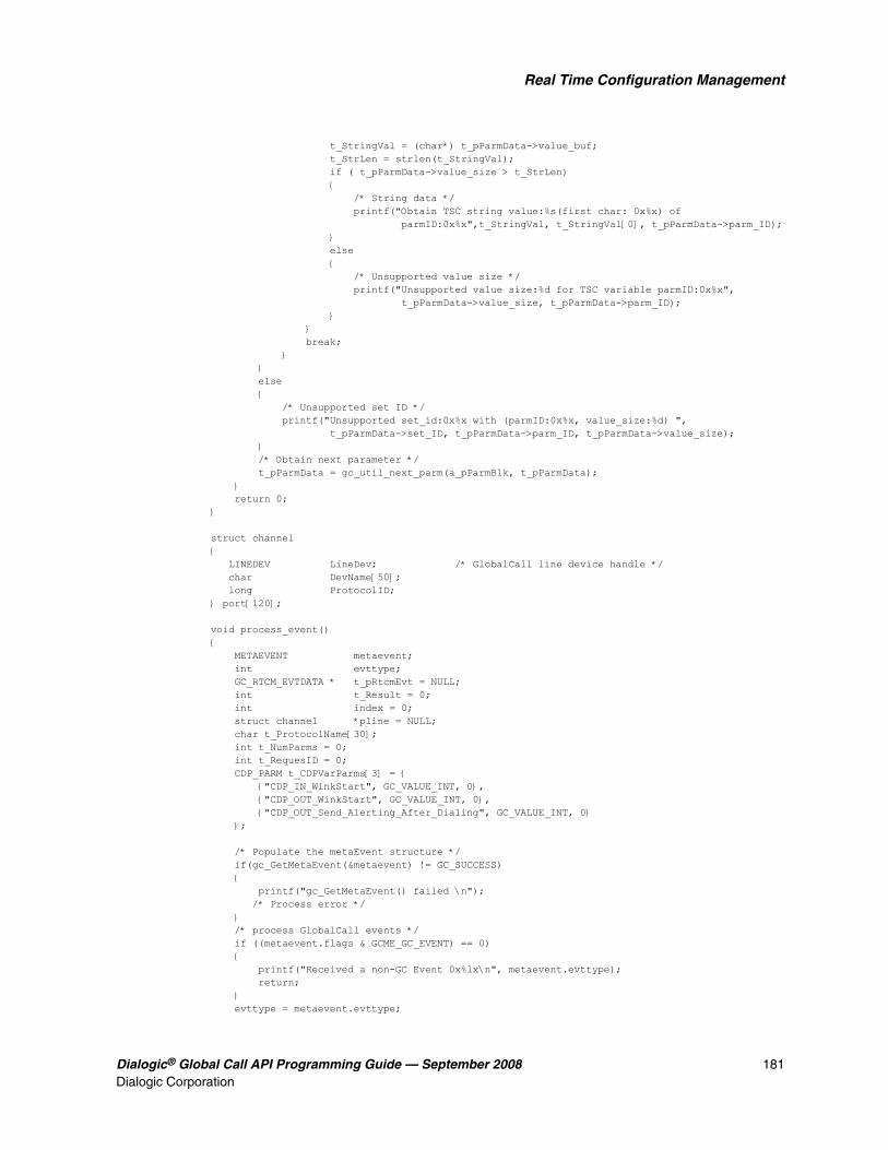
Dialogic® Global Call API Programming Guide — September 2008 181Dialogic Corporation
Real Time Configuration Management
t_StringVal = (char*) t_pParmData->value_buf; t_StrLen = strlen(t_StringVal); if ( t_pParmData->value_size > t_StrLen) { /* String data */ printf("Obtain TSC string value:%s(first char: 0x%x) of parmID:0x%x",t_StringVal, t_StringVal[0], t_pParmData->parm_ID); } else { /* Unsupported value size */ printf("Unsupported value size:%d for TSC variable parmID:0x%x", t_pParmData->value_size, t_pParmData->parm_ID); } } break; } } else { /* Unsupported set ID */ printf("Unsupported set_id:0x%x with (parmID:0x%x, value_size:%d) ", t_pParmData->set_ID, t_pParmData->parm_ID, t_pParmData->value_size); } /* Obtain next parameter */ t_pParmData = gc_util_next_parm(a_pParmBlk, t_pParmData); } return 0;}
struct channel{ LINEDEV LineDev; /* GlobalCall line device handle */ char DevName[50]; long ProtocolID;} port[120];
void process_event(){ METAEVENT metaevent; int evttype; GC_RTCM_EVTDATA * t_pRtcmEvt = NULL; int t_Result = 0; int index = 0; struct channel *pline = NULL; char t_ProtocolName[30]; int t_NumParms = 0; int t_RequesID = 0; CDP_PARM t_CDPVarParms[3] = { {"CDP_IN_WinkStart", GC_VALUE_INT, 0}, {"CDP_OUT_WinkStart", GC_VALUE_INT, 0}, {"CDP_OUT_Send_Alerting_After_Dialing", GC_VALUE_INT, 0} };
/* Populate the metaEvent structure */ if(gc_GetMetaEvent(&metaevent) != GC_SUCCESS) { printf("gc_GetMetaEvent() failed \n"); /* Process error */ } /* process GlobalCall events */ if ((metaevent.flags & GCME_GC_EVENT) == 0) { printf("Received a non-GC Event 0x%lx\n", metaevent.evttype); return; } evttype = metaevent.evttype;

182 Dialogic® Global Call API Programming Guide — September 2008Dialogic Corporation
Real Time Configuration Management
if (metaevent.usrattr) { pline = (struct channel *) metaevent.usrattr; } switch (evttype) { case GCEV_UNBLOCKED: { int t_IntVal = 1; t_Result = ObtainProtocolIDAndName(pline->LineDev, t_ProtocolName, &pline->ProtocolID); if (t_Result) { /* Error processs */ } t_NumParms = 3; t_CDPVarParms[0].valuep = &t_IntVal; t_CDPVarParms[1].valuep = &t_IntVal; t_CDPVarParms[2].valuep = &t_IntVal; /* Setting new values to CDP variables */ t_Result = SetCDPVarParms(pline->ProtocolID, t_NumParms, t_CDPVarParms, &t_RequesID); if (t_Result) { /* Processs error */ } } break; case GCEV_GETCONFIGDATA: t_pRtcmEvt = (GC_RTCM_EVTDATA *) metaevent.evtdatap; if (! t_pRtcmEvt || !t_pRtcmEvt->retrieved_parmblkp) { break; } printf("Received GCEV_GETCONFIGDATA EVENT on target_type=%d, target_id=0x%x, rquest_id=0x%x", t_pRtcmEvt->target_type, t_pRtcmEvt->target_id, t_pRtcmEvt->request_ID); ProcessRTCMEvent(evttype, t_pRtcmEvt->request_ID, t_pRtcmEvt->retrieved_parmblkp); break; /* RETURN POINT!!!!! */ break; case GCEV_SETCONFIGDATA: t_pRtcmEvt = (GC_RTCM_EVTDATA *) metaevent.evtdatap; if (! t_pRtcmEvt) { break; } printf("Received GCEV_SETCONFIGDATA EVENT on target_type=%d, target_id=0x%x, rquest_id=0x%x", t_pRtcmEvt->target_type, t_pRtcmEvt->target_id, t_pRtcmEvt->request_ID); t_NumParms = 3; /* Retrieving existing values from CDP variables */ t_Result = GetCDPVarParms(t_pRtcmEvt->target_id, t_NumParms, t_CDPVarParms, &t_RequesID); if (t_Result) { /* Processs error */ } break; case GCEV_GETCONFIGDATA_FAIL: t_pRtcmEvt = (GC_RTCM_EVTDATA *) metaevent.evtdatap; if (! t_pRtcmEvt) { break; } printf("Received GCEV_GETCONFIGDATA EVENT_FAIL on target_type=%d, target_id=0x%x, rquest_id=0x%x", t_pRtcmEvt->target_type, t_pRtcmEvt->target_id, t_pRtcmEvt->request_ID);

Dialogic® Global Call API Programming Guide — September 2008 183Dialogic Corporation
Real Time Configuration Management
break; case GCEV_SETCONFIGDATA_FAIL: t_pRtcmEvt = (GC_RTCM_EVTDATA *) metaevent.evtdatap; if (! t_pRtcmEvt) { break; } printf("Received GCEV_SETCONFIGDATA_FAIL EVENT on target_type=%d, target_id=0x%x, rquest_id=0x%x", t_pRtcmEvt->target_type, t_pRtcmEvt->target_id, t_pRtcmEvt->request_ID); break; default: break; }}
9.9.6 Dynamically Configuring a Trunk
This feature enables the user to perform the following dynamic configuration operations at run time:
• Setting the Line Type and Coding for a Trunk
• Specifying the Protocol for a Trunk
Note: The gc_SetConfigData( ) function can be used on a board device to perform these operations. However, it is the application's responsibility to handle all active calls on the trunk, and terminate them if necessary. In addition, the gc_ResetLineDev( ) function may be issued on all channels (time slots) prior to issuing gc_SetConfigData( ) to prevent incoming calls. If there are any active calls present at the time the gc_ResetLineDev( ) or gc_SetConfigData( ) function is issued, they are gracefully terminated internally. The application does not receive GCEV_DISCONNECTED events when calls are terminated in this manner.
9.9.6.1 Setting the Line Type and Coding for a Trunk
The gc_SetConfigData( ) function can be used on the board device to reconfigure the line type for the trunk. The gc_SetConfigData( ) function uses a GC_PARM_BLK structure that contains the configuration information. The GC_PARM_BLK is populated using the gc_util_insert_parm_val( ) function.
To configure the line type, use the gc_util_insert_parm_val( ) function with the following parameter values:
• parm_blkpp = pointer to the address of a valid GC_PARM_BLK structure where the parameter and value are to be inserted
• setID = CCSET_LINE_CONFIG
• parmID = CCPARM_LINE_TYPE
• data_size = sizeof(int)
• data = One of the following values:
– Enum_LineType_dsx1_D4 - D4 framing type, Superframe (SF)
– Enum_LineType_dsx1_ESF - Extended Superframe (ESF)
– Enum_LineType_dsx1_E1 - E1 standard framing
– Enum_LineType_dsx1_E1_CRC - E1 standard framing and CRC-4

184 Dialogic® Global Call API Programming Guide — September 2008Dialogic Corporation
Real Time Configuration Management
To configure the coding type, use the gc_util_insert_parm_val( ) function with the following parameter values:
• parm_blkpp = pointer to the address of a valid GC_PARM_BLK structure where the parameter and value are to be inserted
• setID = CCSET_LINE_CONFIG
• parmID = CCPARM_CODING_TYPE
• data_size = sizeof(int)
• data = One of the following values:
– Enum_CodingType_AMI - Alternate Mark Inversion
– Enum_CodingType_B8ZS - Modified AMI used on T1 lines
– Enum_CodingType_HDB3 - High Density Bipolar of Order 3 used on E1 lines
Once the GC_PARM_BLK has been populated with the desired values, the gc_SetConfigData( ) function can be issued to perform the configuration. The parameter values for the gc_SetConfigData( ) function are as follows:
• target_type = GCTGT_CCLIB_NETIF
• target_id = the trunk line device handle, as obtained from gc_OpenEx( ) with a devicename string of “:N_dtiBx:P...”
• target_datap = GC_PARM_BLKP parameter pointer, as constructed by the utility function gc_util_insert_parm_val( )
• time_out = time interval (in seconds) during which the target object must be updated with the data. If the interval is exceeded, the update request is ignored. This parameter is supported in synchronous mode only, and it is ignored when set to 0.
• update_cond = GCUPDATE_IMMEDIATE
• request_idp = pointer to the location for storing the request ID
• mode = EV_ASYNC for asynchronous execution or EV_SYNC for synchronous execution
The application receives one of the following events:
• GCEV_SETCONFIGDATA to indicate that the request to dynamically change the line type and/or coding has been successfully initiated.
• GCEV_SETCONFIGDATA_FAIL to indicate that the request to dynamically change the line type and/or coding failed. More information is available from the GC_RTCM_EVTDATA structure associated with the event.
The following code example shows how to dynamically configure a T1 trunk to operate with the Extended Superframe (ESF) line type and the B8ZS coding type.
GC_PARM_BLKP ParmBlkp = NULL;long id;
/* configure Line Type = Extended Superframe for a T1 trunk */ gc_util_insert_parm_val(&ParmBlkp, CCSET_LINE_CONFIG, CCPARM_LINE_TYPE, sizeof(int), Enum_LineType_dsx1_ESF);
/* configure Coding Type = B8ZS for a T1 trunk */gc_util_insert_parm_val(&ParmBlkp, CCSET_LINE_CONFIG, CCPARM_CODING_TYPE, sizeof(int), Enum_CodingType_B8ZS);

Dialogic® Global Call API Programming Guide — September 2008 185Dialogic Corporation
Real Time Configuration Management
gc_SetConfigData(GCTGT_CCLIB_NETIF, bdev, ParmBlkp, 0, GCUPDATE_IMMEDIATE, &id, EV_ASYNC); gc_util_delete_parm_blk(ParmBlkp);
if (sr_waitevt(-1) >= 0) { METAEVENT meta; gc_GetMetaEvent(&meta); switch(sr_getevttype()) { case GCEV_SETCONFIGDATA: printf("Received event GCEV_SETCONFIGDATA(ReqID=%d) on device %s \n",((GC_RTCM_EVTDATA *)(meta.evtdatap))->request_ID, ATDV_NAMEP(sr_getevtdev())); break; case GCEV_SETCONFIGDATA_FAIL: printf("Received event GCEV_SETCONFIGDATA_FAIL(ReqID=%d) on device %s, Error=%s\n",((GC_RTCM_EVTDATA *)(meta.evtdatap))->request_ID, ATDV_NAMEP(sr_getevtdev()), ((GC_RTCM_EVTDATA *)(meta.evtdatap))->additional_msg); break; default: printf("Received event 0x%x on device %s\n", sr_getevttype(), ATDV_NAMEP(sr_getevtdev())); break; }}
9.9.6.2 Specifying the Protocol for a Trunk
The protocol used by a trunk can be dynamically configured after devices have been opened using the gc_SetConfigData( ) function. All channels on the affected trunk inherit the newly selected protocol.
The gc_SetConfigData( ) function uses a GC_PARM_BLK structure that contains the configuration information. The GC_PARM_BLK is populated using the gc_util_insert_parm_ref( ) function.
To configure the protocol, use the gc_util_insert_parm_ref( ) function with the following parameter values:
• parm_blkpp = pointer to the address of a valid GC_PARM_BLK structure where the parameter and value are to be inserted
• setID = GCSET_PROTOCOL
• parmID = GCPARM_PROTOCOL_NAME
• data_size = strlen(“<protocol_name>”), for example, strlen(“4ESS”)
• data = “<protocol_name>”, for example, “4ESS” (a null-terminated string). For ISDN protocols, the protocol name must be one of the supported protocols listed in the CONFIG file that corresponds to the PCD/FCD file that is downloaded. Only protocols of the same line type can be selected; that is, if the trunk is of line type E1, then only a protocol variant that is valid for E1 can be selected.

186 Dialogic® Global Call API Programming Guide — September 2008Dialogic Corporation
Real Time Configuration Management
Once the GC_PARM_BLK has been populated with the desired values, the gc_SetConfigData( ) function can be issued to perform the configuration. The parameter values for the gc_SetConfigData( ) function are as follows:
• target_type = GCTGT_CCLIB_NETIF
• target_id = the trunk line device handle, as obtained from gc_OpenEx( ) with a devicename string of “:N_dtiBx:P...”
• target_datap = GC_PARM_BLKP parameter pointer, as constructed by the utility function gc_util_insert_parm_ref( )
• time_out = time interval (in seconds) during which the target object must be updated with the data. If the interval is exceeded, the update request is ignored. This parameter is supported in synchronous mode only, and it is ignored when set to 0.
• update_cond = GCUPDATE_IMMEDIATE
• request_idp = pointer to the location for storing the request ID
• mode = EV_ASYNC for asynchronous execution or EV_SYNC for synchronous execution
The application receives one of the following events:
• GCEV_SETCONFIGDATA to indicate that the request to dynamically change the protocol has been successfully initiated.
• GCEV_SETCONFIGDATA_FAIL to indicate that the request to change the protocol has failed. More information is available from the GC_RTCM_EVTDATA structure associated with the event.
The following code example shows how to dynamically configure a T1 trunk to operate with the 4ESS protocol.
static int MAX_PROTOCOL_LEN=20; GC_PARM_BLKP ParmBlkp = NULL; long id; char protocol_name[]="4ESS";
gc_util_insert_parm_ref(&ParmBlkp, GCSET_PROTOCOL, GCPARM_PROTOCOL_NAME, strlen(protocol_name)+1, protocol_name);
gc_SetConfigData(GCTGT_CCLIB_NETIF, bdev, ParmBlkp, 0, GCUPDATE_IMMEDIATE, &id, EV_ASYNC);gc_util_delete_parm_blk(ParmBlkp);
if (sr_waitevt(-1) >= 0) { METAEVENT meta; gc_GetMetaEvent(&meta);
switch(sr_getevttype()) { case GCEV_SETCONFIGDATA: printf("Received event GCEV_SETCONFIGDATA(ReqID=%d) on device %s \n",((GC_RTCM_EVTDATA *)(meta.evtdatap))->request_ID, ATDV_NAMEP(sr_getevtdev())); break; case GCEV_SETCONFIGDATA_FAIL: printf("Received event GCEV_SETCONFIGDATA_FAIL(ReqID=%d) on device %s, Error=%s\n",((GC_RTCM_EVTDATA *)(meta.evtdatap))->request_ID, ATDV_NAMEP(sr_getevtdev()), ((GC_RTCM_EVTDATA *)(meta.evtdatap))->additional_msg); break;

Dialogic® Global Call API Programming Guide — September 2008 187Dialogic Corporation
Real Time Configuration Management
default: printf("Received event 0x%x on device %s\n", sr_getevttype(), ATDV_NAMEP(sr_getevtdev())); break; }}
9.9.7 Applicable Data Structures, Set IDs, and Parm IDs
The following sections discuss these topics:
• GC_RTCM_EVTDATA
• Data Structures for CAS Signals
• Set IDs and Parm IDs
9.9.7.1 GC_RTCM_EVTDATA
The GC_RTCM_EVTDATA structure, defined in the gclib.h file, is generally associated with Global Call RTCM events (namely, GCEV_SETCONFIGDATA, GCEV_SETCONFIGDATA_FAIL, GCEV_GETCONFIGDATA, and GCEV_GETCONFIGDATA_FAIL).
The target_type and target_id fields enable applications to identify the DM3 protocol object associated with an event. Note that the line_dev and crn accessed by the evtdatap pointer in the METAEVENT structure are zero for DM3 protocol target objects.
The following shows the GC_RTCM_EVTDATA data structure with the target_type and target_id fields shown in bold text:
typedef struct{ long request_ID; /* The RTCM request ID */ int gc_result; /* GC result value for this event */ int cclib_result; /* CCLib result value for this event */ int cclib_ID; /* CCLib ID for the result */ char * additional_msg; /* Additional message for this event */ GC_PARM_BLKP retrieved_parmblkp; /* Retrieved GC_PARM_BLK -- */ /* used for gc_GetConfigData() in */ /* asynchronous mode */ int target_type; /* Target type */ long target_id; /* Target ID */} GC_RTCM_EVTDATA, *GC_RTCM_EVTDATAP;
9.9.7.2 Data Structures for CAS Signals
Data structures that are used by the gc_SetConfigData( ) and gc_GetConfigData( ) functions to retrieve/modify the CAS signal definitions associated with a PDK protocol are defined in the gclib.h file:
• CAS Transition Signal
• CAS Pulse Signal
• CAS Train Signal

188 Dialogic® Global Call API Programming Guide — September 2008Dialogic Corporation
Real Time Configuration Management
As a convenience that enables the user to enter a new CAS signal definition and retrieve the current CAS signal definition, the fields in these data structures strictly follow the same sequence as the CAS signal definitions in the PDK CDP file. Since CAS signal defines in the CDP file apply to both Dialogic® DM3 and Dialogic® Springware Boards, some time parameters may not be supported on DM3 Boards. Also, ASCII characters are used to represent signal bit codes in the data structures. For example, “11xx” represents signal bits 11xx (where x represents “don't care”). All time parameters have units in milliseconds with a resolution of 4 milliseconds.
The following define for the size of the CAS signal bits string is common to all three structures following:
#define GCVAL_CAS_CODE_SIZE 0x5 /* The size of CAS Signal code in string */
CAS Transition Signal
/* Data structure for CAS Transition signal */typedef struct { char PreTransCode[GCVAL_CAS_CODE_SIZE]; /* ABCD pre-transition code */ char PostTransCode[GCVAL_CAS_CODE_SIZE]; /* ABCD post-transition code */ unsigned short PreTransInterval; /* The minimum time for the duration of the pre-transition (in msec)*/ unsigned short PostTransInterval; /* The minimum time for the duration of the post-transition (in msec)*/ unsigned short PreTransIntervalNom; /* The nominal time for the duration of the pre-transition (in msec). Ignored in DM3: always 0 */ unsigned short PostTransIntervalNom; /* The nominal time for the duration of the post-transition (in msec). Ignored in DM3: always 0 */} GC_CASPROT_TRANS;
CAS Pulse Signal
/* Data structure of CAS Pulse signal */typedef struct { char OffPulseCode[GCVAL_CAS_CODE_SIZE]; /* ABCD pulse off code */ char OnPulseCode[GCVAL_CAS_CODE_SIZE]; /* ABCD pulse on code */ unsigned short PrePulseInterval; /* The minimum time for the duration of the pre-pulse (in msec) */ unsigned short PostPulseInterval; /* The minimum time for the duration of the post-pulse (in msec) */ unsigned short PrePulseIntervalNom; /* The nominal time for the duration of the pre-pulse. Ignored in DM3: always 0 */ unsigned short PostPulseIntervalNom; /* The nominal time for the duration of the post-pulse (in msec). Ignored in DM3: always 0 */ unsigned short PulseIntervalMin; /* The minimum time for the duration of the pulse interval (in msec) */ unsigned short PulseIntervalNom; /* The nominal time for the duration of the pulse interval (in msec) */ unsigned short PulseIntervalMax; /* The maximum time for the duration of the pulse interval (in msec) */} GC_CASPROT_PULSE;
CAS Train Signal
/* Data structure of CAS Train signal */typedef struct { char OffPulseCode[GCVAL_CAS_CODE_SIZE]; /* ABCD pulse off code */ char OnPulseCode[GCVAL_CAS_CODE_SIZE]; /* ABCD pulse on code */ unsigned short PreTrainInterval; /* The minimum time for the duration

Dialogic® Global Call API Programming Guide — September 2008 189Dialogic Corporation
Real Time Configuration Management
of the pre-train (in msec) */ unsigned short PostTrainInterval; /* The minimum time for the duration of the post-train (in msec) */ unsigned short PreTrainIntervalNom; /* The nominal time for the duration of the pre-train. Ignored in DM3: always 0 */ unsigned short PostTrainIntervalNom; /* The nominal time for the duration of the post-train (in msec). Ignored in DM3: always 0 */ unsigned short PulseIntervalMin; /* The minimum time for the duration of the pulse interval (in msec)*/ unsigned short PulseIntervalNom; /* The nominal time for the duration of the pulse interval (in msec)*/ unsigned short PulseIntervalMax; /* The maximum time for the duration of the pulse interval (in msec)*/ unsigned short InterPulseIntervalMin; /* The minimum time for the duration of inter-pulse interval (in msec)*/ unsigned short InterPulseIntervalNom; /* The nominal time for the duration of inter-pulse interval (in msec)*/ unsigned short InterPulseIntervalMax; /* The maximum time for the duration of inter-pulse interval (in msec) */} GC_CASPROT_TRAIN;
CAS Signal Type Defines
The following value types for CAS signal parameter are defined in the gccfgparm.h file to represent the CAS Transition, CAS Pulse, and CAS Train types, respectively. These defines are used by the gc_QueryConfigData( ) for the value type of CAS signal.
GC_VALUE_CAS_TRANS = 0x10, /* CAS Transition data struture ==> GC_CASPROT_TRANS */ GC_VALUE_CAS_PULSE = 0x11, /* CAS Pulse data struture ==> GC_CASPROT_PULSE */ GC_VALUE_CAS_TRAIN = 0x12, /* CAS Train data struture ==> GC_CASPROT_TRAIN */
Other value types (for example, integer, string, long, etc.) are also defined in the gccfgparm.h file.
9.9.7.3 Set IDs and Parm IDs
This feature uses the following Set IDs and Parm IDs:
9.9.8 Restrictions and Limitations
The following restrictions and limitations apply:
• This feature supports the redefinition of CAS signals and the setting of CDP variable values for a specific protocol variant, which will affect all channels running that protocol variant. It does not, however, support the getting or setting of protocol parameters on an individual
Set ID Parm IDs
CCSET_LINE_CONFIG CCPARM_LINE_TYPE
CCPARM_CODING_TYPE
GCSET_PROTOCOL GCPARM_PROTOCOL_ID
GCPARM_PROTOCOL_NAME
PRSET_CAS_SIGNAL(defined in dm3cc_parm.h)
The parm ID is dynamically generated.
PRSET_TSC_VARIABLE(defined in dm3cc_parm.h)
The parm ID is dynamically generated.

190 Dialogic® Global Call API Programming Guide — September 2008Dialogic Corporation
Real Time Configuration Management
channel basis. Getting and setting CAS signal definitions or CDP variable values is only supported for PDK protocols.
• Prior to changing parameters of a protocol, all channels running the protocol should be in the Idle state (that is, there should be no call activity on the channels). Once the parameter value change is complete, reset the channels running the affected protocol.
• At least one time slot has to remain open while setting or retrieving CAS signal definitions or CDP variable values.
• Using this feature to set/get multiple CAS signal definitions in a single GC_PARM_BLK via the gc_SetConfigData( ) and gc_GetConfigData( ) functions, or mixing CAS signal definitions with other parameters, is not supported. Only one CAS signal definition (and no other parameters) can be included in any one function call.
• The API for this feature can be used only after the board firmware has been downloaded.
• Configuration files are not updated with changes made using this API for this feature. The API does not save or store the changes made; and if the firmware is re-downloaded, all information configured using this API will be lost. It is the API user’s responsibility to save or store the changed configuration information and reset via the API in the event of a re-download.
• This feature supports the redefinition of CAS Transition, CAS Pulse, and CAS Train signals only. In addition, this feature does not support the changing of the CAS signal type during redefinition. For example, the CAS_WINKRCV signal type cannot be changed from a CAS Pulse to a CAS Transition.
• Error checking and checking the validity of parameters passed through this API are the responsibilities of the API user.
• The list of parameters that need to be modified must be managed at run time. Parameter updates are sent to the firmware one at a time, as opposed to the parallel procedures used to set parameters at firmware download time. The list of parameters that need modification should be kept to a minimum.
• This feature supports the setting and retrieval of multiple CDP variable values in a single API call, but it does not support the mixing of CDP variables with other parameters when setting or retrieving values.
• To set the values of the CDP_IN_ANI_Enabled and CDP_OUT_ANI_Enabled parameters in the pdk_us_mf_io.cdp file, the user is required to remove feature_ANI from the SYS_FEATURES section of the CDP file. Similarly, to set the values of the CDP_IN_DNIS_Enabled and CDP_OUT_DNIS_Enabled parameters, the user is required to remove feature_DNIS from the SYS_FEATURES section.

Dialogic® Global Call API Programming Guide — September 2008 191Dialogic Corporation
1010.Handling Service Requests
This chapter describes the Dialogic® Global Call API Service Request (GCSR) feature. Topics include the following:
• Service Request Overview. . . . . . . . . . . . . . . . . . . . . . . . . . . . . . . . . . . . . . . . . . . . . . . 191
• Service Request Components . . . . . . . . . . . . . . . . . . . . . . . . . . . . . . . . . . . . . . . . . . . . 192
• Service Request Data. . . . . . . . . . . . . . . . . . . . . . . . . . . . . . . . . . . . . . . . . . . . . . . . . . . 193
• General Service Request Scenario. . . . . . . . . . . . . . . . . . . . . . . . . . . . . . . . . . . . . . . . . 193
• ISDN BRI-Specific Service Request Scenario . . . . . . . . . . . . . . . . . . . . . . . . . . . . . . . 194
10.1 Service Request Overview
The Dialogic® Global Call API Service Request (GCSR) feature is an optional feature that allows a device to send a request to another remote device for some kind of service. Some examples of the services that may be requested are:
• Device registration
• Channel setup
• Call setup
• Information requests
• Operational requests
In general, this feature is useful when a Global Call application needs to make a request between two Global Call devices across a network.
Some examples of typical uses are:
• Registration requests
• Administration requests (for example, logon requests)
• Bandwidth requests
• Capabilities requests (for example, determining remote-side capabilities)
• Preference requests (for example, informing remote-side of setup preferences)
Since this is a generic feature, the capabilities in a given technology are largely dependent on the support provided by the call control libraries for that technology. Refer to the appropriate Dialogic® Global Call Technology Guide for more information.
Figure 41 shows the architecture of the GCSR feature.

192 Dialogic® Global Call API Programming Guide — September 2008Dialogic Corporation
Handling Service Requests
Figure 41. Service Request Architecture
10.2 Service Request Components
Using the Dialogic® Global Call API Service Request (GCSR) feature involves the following API components:
gc_ReqService( ) function to make a request
gc_RespService( ) function to respond to a request
GCEV_SERVREQ an event indicating that a request has been received
GCEV_SERVRESP an event indicating a response has been received; therefore, this is also a termination event for the gc_ReqService( ) function
GCEV_SERVRESPCMPLT termination event for the gc_RespService( ) function
When using the GCSR, all requests and responses are to be made on specific device targets (that is, LDID, CRN); and, depending on the type of request and the call control library used, additional
CUSTOMER APPLICATIONOperation and ConfigurationSubsystem
Global CallOperation andConfigurationSubsystem
GCSR
CALLCONTROLLIBRARY
NetworkInterface
RemoteDevice

Dialogic® Global Call API Programming Guide — September 2008 193Dialogic Corporation
Handling Service Requests
restrictions may apply. See the appropriate Dialogic® Global Call Technology Guide for more information.
10.3 Service Request Data
All information transmitted and received using the Service Request feature is done using the generic GC_PARM_BLK data structure. Three parameter IDs, under the GCSET_SERVREQ set ID, are used for all requests and responses:
PARM_SERVICEID (unsigned long) the service identification number. This is a number assigned by the call control library to distinguish between requests. It is used as follows:
• When making a request (gc_ReqService( )), ignore this field.
• When generating a response (gc_RespService( )), this value needs to be set to the same ID as the ID of the received request (through GCEV_SERVREQ).
• When receiving a response (through GCEV_SERVRESP), this field should match the ID assigned when the request was first made.
PARM_REQTYPE (int) the type of request made. Refer to the appropriate Dialogic® Global Call Technology Guide for the actual values.
PARM_ACK (short) the acknowledgment field. It is used as follows:
• When used for a service request, a value of GC_ACK indicates that a response is required, and a value of GC_NACK indicates that no response is necessary.
• When used for a service response, a value of GC_ACK indicates a confirmation, and a value of GC_NACK indicates a rejection.
Depending on the call control library used, additional parameters may also be used.
Before the Service Request feature can be used, a GC_PARM_BLK data structure must be set up to handle the data associated with the service request. Each request or response is assigned a Service ID by the call control library and should be used by the application when generating responses as well as to distinguish among different requests and responses. See the GC_PARM_BLK data structure and utility functions (gc_util_xxx) in the Dialogic® Global Call API Library Reference for more information on setting up the data structure for the Service Request feature.
Notes: 1. When using the gc_ReqService( ) function, PARM_REQTYPE and PARM_ACK are mandatory parameters of the GC_PARM_BLK pointed to by the reqdatap function parameter.
2. When using the gc_RespService( ) function, PARM_SERVICEID is a mandatory parameter of the GC_PARM_BLK pointed to by the datap function parameter.
10.4 General Service Request Scenario
Figure 42 is a general scenario of how the Service Request feature operates in asynchronous mode. Since the Service Request feature is generic, the nature of each request and response depends on

194 Dialogic® Global Call API Programming Guide — September 2008Dialogic Corporation
Handling Service Requests
the underlying call control library. Refer to the appropriate Dialogic® Global Call Technology Guide for more information.
Figure 42. Generic Service Request Operation
10.5 ISDN BRI-Specific Service Request Scenario
In ISDN BRI, the request for device registration is automatically generated when the device is initialized, so this feature is essentially used in a response-only manner by the network side. See Figure 43.
RequestingApplication
RequestingDevice
RespondingApplication
gc_ReqService ()
RespondingDevice
GCEV_SERVICEREQ*
Generate Request
Notificationof Request
Process Request
gc_RespService ()
Generate Response
Notificationof Response
GCEV_SERVICERESP*
Note: * Indicates that the extdatap of each of these events contains a pointer to GC_PARM_BLK, which in turn contains all the information associated with the corresponding request or response. The pointer is only valid until the next call to gc_GetMetaEvent () or gc_GetMetaEventEx ().

Dialogic® Global Call API Programming Guide — September 2008 195Dialogic Corporation
Handling Service Requests
Figure 43. ISDN BRI Service Request Operation
UserApplication
UserDevice
NetworkApplication
gc_OpenEx ()
NetworkDevice
GCEV_SERVICEREQ
Process
Generate Response
GCEV_SERVICERESP
GCEV_UNBLOCKED
gc_SetConfigData ()
Send SPID
Verify SPID
gc_RespService ()

196 Dialogic® Global Call API Programming Guide — September 2008Dialogic Corporation
Handling Service Requests

Dialogic® Global Call API Programming Guide — September 2008 197Dialogic Corporation
1111.Using Dialogic® Global Call API to Implement Call Transfer
The information in this chapter is technology independent; however, it describes a method of call transfer that is supported by IP technology only. For more specific information about implementing call transfer on IP technology, see the Dialogic® Global Call IP Technology Guide. The topics discussed in this chapter are:
• Introduction to Call Transfer . . . . . . . . . . . . . . . . . . . . . . . . . . . . . . . . . . . . . . . . . . . . . 197
• Call Transfer State Machine . . . . . . . . . . . . . . . . . . . . . . . . . . . . . . . . . . . . . . . . . . . . . 198
11.1 Introduction to Call Transfer
The Dialogic® Global Call API supports the following call transfer methods:
• Blind Call Transfer
• Supervised Call Transfer
11.1.1 Blind Call Transfer
In a blind call transfer scenario (Figure 44), party A transfers the call between A and B (Call 1) to a call between party B and C without consulting party C. Party A places the primary call (Call 1) on hold, directly dials the party C address, and then disconnects from Call 1 before the second call (Transferred-to call, Call 2 - between B and C) is established. Party A may also request party B to dial party C's address and then disconnect from Call 1 after Call 2 between B and C has been established.
Before call transfer can occur, party A must be in a call with party B (Primary Call, Call 1).
Note: In the scenario shown in Figure 44, party B initiates the transferred call to party C.

198 Dialogic® Global Call API Programming Guide — September 2008Dialogic Corporation
Using Dialogic® Global Call API to Implement Call Transfer
Figure 44. Blind Call Transfer (Unsupervised Transfer)
11.1.2 Supervised Call Transfer
In a supervised call transfer scenario (Figure 45), party A transfers the call between A and B (Call 1) to a call between party B and C after establishing a consultation call with party C. In this call, party A informs Transferred-to party C of the intent of transferring party B to party C and collects the feedback and rerouting address from party C. Party A requests that party B dial party C’s address (rerouting address) and then disconnect from Calls 1 and 2 after Call 3 (Transferred-to call) between party B and party C has been established.
Before call transfer can occur, party A must be in a call with party B (Primary Call, Call 1).
Figure 45. Supervised Call Transfer
11.2 Call Transfer State Machine
Table 18 lists the Dialogic® Global Call API call states for blind call transfer.
Transferred_To_Party (C)
TransferringParty (A)
TransferredParty (B)
Call 1
Before Blind Transfer
TransferringParty (A)
TransferredParty (B)
Transferred_To_Party (C)
Call 1
Call 2
TransferringParty (A)
TransferredParty (B)
Call 2
Blind Call Transfer After Blind Transfer
Transferred_To_Party (C)
Transferred_To_Party (C)
TransferringParty (A)
TransferredParty (B)
Call 1
Before Transfer
TransferringParty (A)
TransferredParty (B)
Transferred_To_Party (C)
Call 1
Call 2
TransferringParty (A)
TransferredParty (B)
Call 3
Call 2 Setup Call 3 Setup
Transferred_To_Party (C)
Call 1
Call 2
TransferredParty (B)
Call 3
After Call Transfer
Transferred_To_Party (C)
TransferringParty (A)
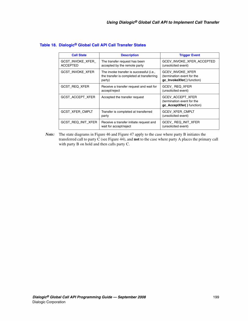
Dialogic® Global Call API Programming Guide — September 2008 199Dialogic Corporation
Using Dialogic® Global Call API to Implement Call Transfer
Note: The state diagrams in Figure 46 and Figure 47 apply to the case where party B initiates the transferred call to party C (see Figure 44), and not to the case where party A places the primary call with party B on hold and then calls party C.
Table 18. Dialogic® Global Call API Call Transfer States
Call State Description Trigger Event
GCST_INVOKE_XFER_ACCEPTED
The transfer request has been accepted by the remote party
GCEV_INVOKE_XFER_ACCEPTED (unsolicited event)
GCST_INVOKE_XFER The invoke transfer is successful (i.e., the transfer is completed at transferring party)
GCEV_INVOKE_XFER (termination event for the gc_InvokeXfer( ) function)
GCST_REQ_XFER Receive a transfer request and wait for accept/reject
GCEV_ REQ_XFER (unsolicited event)
GCST_ACCEPT_XFER Accepted the transfer request GCEV_ACCEPT_XFER (termination event for the gc_AcceptXfer( ) function)
GCST_XFER_CMPLT Transfer is completed at transferred party
GCEV_XFER_CMPLT (unsolicited event)
GCST_REQ_INIT_XFER Receive a transfer initiate request and wait for accept/reject
GCEV_ REQ_INIT_XFER(unsolicited event)

200 Dialogic® Global Call API Programming Guide — September 2008Dialogic Corporation
Using Dialogic® Global Call API to Implement Call Transfer
Figure 46. Call State Model for Blind Call Transfer at Party A
GCST_NULL
GCST_IDLE
GCST_INVOKE_XFER
GCEV_DISCONNECTED(XFER CMPLT)
GCEV_RELEASECALL
Transferring Party(Party A)
GCEV_INVOKE_XFER_FAIL
GCST_INVOKE_XFER_ACCEPTED
GCST_CONNECTED orGCST_HOLD
GCEV_INVOKE_XFER
GCEV_INVOKE_XFER
GCEV_INVOKE_XFER_ACCEPTED
GCEV_INVOKE_XFER_REJGCEV_INVOKE_XFER_FAIL
GCST_DISCONNECTED
GCEV_DROPCALL

Dialogic® Global Call API Programming Guide — September 2008 201Dialogic Corporation
Using Dialogic® Global Call API to Implement Call Transfer
Figure 47. Call State Model for Blind Call Transfer at Party B
GCST_CONNECTED orGCST_HELD
GCST_NULL
GCST_IDLE
GCST_REQ_XFER
GCEV_REQ_XFER
GCEV_DROPCALL
GCEV_RELEASECALL
Transferred Party
(Party B)
GCEV_REJ_XFERGCEV_ACCEPT_XFER_FAILGCEV_REJ_XFER_FAIL
GCST_DISCONNECTED
GCEV_XFER_CMPLT
gc_MakeCall(CRN2 )
GCST_ALERTING
GCST_CONNECTED
GCST_PROCEEDING
GCEV_PROCEEDING
GCEV_CONNECTED
GCST_DIALING
GCEV_ALERTING
GCST_ACCEPT_XFER
GCEV_ACCEPT_XFER
GCST_XFER_CMPLT
GCEV_DISCONNECTED(XFER CMPLT)
GCEV_XFER_FAIL
Transferred-to Party (Party C) - the rerouting call is same as new incoming call, exceptGCEV_DETECTGED / GCEV_OFFERED with a flag indicating a transfer call
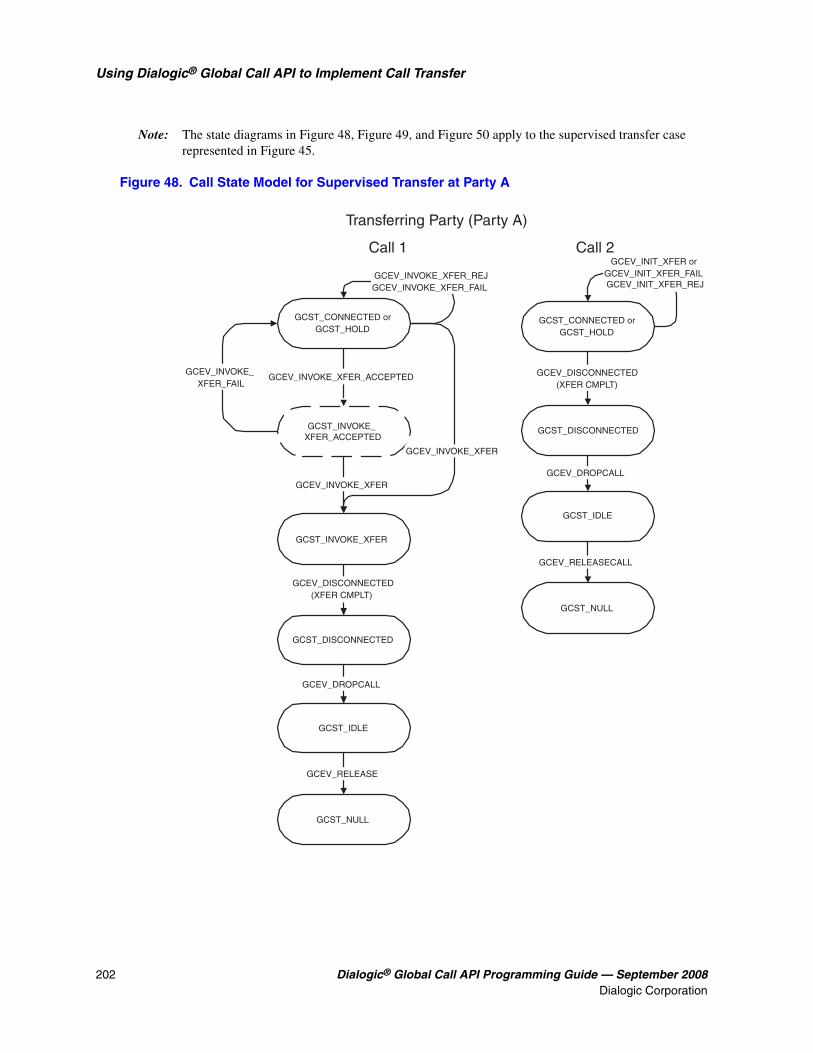
202 Dialogic® Global Call API Programming Guide — September 2008Dialogic Corporation
Using Dialogic® Global Call API to Implement Call Transfer
Note: The state diagrams in Figure 48, Figure 49, and Figure 50 apply to the supervised transfer case represented in Figure 45.
Figure 48. Call State Model for Supervised Transfer at Party A
GCEV_INVOKE_XFER_FAIL
GCST_INVOKE_XFER
GCST_INVOKE_XFER_ACCEPTED
GCST_CONNECTED orGCST_HOLD
GCEV_INVOKE_XFER
GCEV_INVOKE_XFER
Transferring Party (Party A)
GCST_NULL
GCST_IDLE
GCST_CONNECTED orGCST_HOLD
GCEV_INIT_XFER orGCEV_INIT_XFER_FAILGCEV_INIT_XFER_REJ
GCEV_DROPCALL
GCEV_RELEASECALL
GCST_DISCONNECTED
GCST_NULL
GCEV_RELEASE
Call 1 Call 2
GCST_IDLE
GCEV_DISCONNECTED(XFER CMPLT)
GCEV_INVOKE_XFER_ACCEPTED
GCEV_INVOKE_XFER_REJGCEV_INVOKE_XFER_FAIL
GCST_DISCONNECTED
GCEV_DROPCALL
GCEV_DISCONNECTED(XFER CMPLT)

Dialogic® Global Call API Programming Guide — September 2008 203Dialogic Corporation
Using Dialogic® Global Call API to Implement Call Transfer
Figure 49. Call State Model for Supervised Transfer at Party B
GCST_XFER_CMPLT
GCST_ACCEPT_XFER
GCST_CONNECTED orGCST_HELD
GCEV_REQ_XFER
GCEV_XFER_CMPLT
Call 1
GCEV_XFER_FAIL
GCST_DISCONNECTED
GCEV_DISCONNECTED
GCST_NULL
GCEV_RELEASE
GCST_IDLE
GCEV_DROPCALL
GCST_DIALING
GCST_CONNECTED
GCST_ALERTING
GCEV_ALERTING
GCEV_CONNECTED
GCST_PROCEEDING
GCEV_PROCEEDING
Call 3
GCST_REQ_XFER
GCEV_ACCEPT_XFER
GCEV_ACCEPT_XFER_FAILGCEV_REJ_XFER
GCEV_REJ_XFER_FAIL
gc_MakeCall(C3)
Transferred Party (Party B)

204 Dialogic® Global Call API Programming Guide — September 2008Dialogic Corporation
Using Dialogic® Global Call API to Implement Call Transfer
Figure 50. Call State Model for Supervised Transfer at Party C
GCST_CONNECTED orGCST_HELD
GCST_REQ_INIT_XFER
GCEV_REQ_INIT_XFER
GCEV_ACCEPT_INIT_XFER orGCEV_REJ_INIT_XFER or
GCEV_REJ_INIT_XFER_FAIL orGCEV_ACCEPT_INIT_XFER_FAIL
Call 2
GCST_IDLE
GCST_CONNECTED
GCST_OFFERED
GCEV_OFFERED
GCEV_ANSWERED
GCEV_DISCONNECTED
Call 3
GCST_DISCONNECTED
GCST_NULL
GCEV_RELEASE
GCST_IDLE
GCEV_DROPCALL
GCEV_DISCONNECTED(XFER CMPLT)
GCST_DISCONNECTED
Transferred-To Party (Party C)
GCST_DETECTED
GCEV_DETECTED

Dialogic® Global Call API Programming Guide — September 2008 205Dialogic Corporation
1212.Building Applications
This chapter provides general information for building applications that use the Dialogic® Global Call API. For additional technology-specific information, refer to the appropriate Dialogic® Global Call Technology Guide. Topics included in this chapter are:
• Compiling and Linking in Linux . . . . . . . . . . . . . . . . . . . . . . . . . . . . . . . . . . . . . . . . . . 205
• Compiling and Linking in Windows® . . . . . . . . . . . . . . . . . . . . . . . . . . . . . . . . . . . . . . 206
12.1 Compiling and Linking in Linux
An application that uses the Dialogic® Global Call API must include references to the Global Call header files and must include the appropriate library files. This information is provided the following topics:
• Include Files
• Required Libraries
• Variables for Compiling and Linking Commands
12.1.1 Include Files
The following header files contain equates that are required for each application that uses the Dialogic® Global Call API library:
gclib.h primary Global Call header file
gcerr.h header file containing equates for error codes
Note: See the appropriate Dialogic® Global Call Technology Guide for technology-specific header files.
12.1.2 Required Libraries
The following library files must be linked to the application in the following order:
libgc.so the primary Dialogic® Global Call API shared object file. Linking this file is mandatory. Use the -lgc argument to the system linker.
libdxxx.so the primary Dialogic® Voice API shared object file. This library is only required if the application uses Voice library functions directly, for example, dx_play( ).
Note: When compiling an application, you must list Dialogic® libraries first before all other libraries, such as operation system libraries.

206 Dialogic® Global Call API Programming Guide — September 2008Dialogic Corporation
Building Applications
12.1.3 Variables for Compiling and Linking Commands
The following variables provide a standardized way of referencing the directories that contain header files and shared objects:
INTEL_DIALOGIC_INCVariable that points to the directory where header files are stored
INTEL_DIALOGIC_LIBVariable that points to the directory where shared library files are stored
These variables are automatically set at login and should be used in compiling and linking commands. The following is an example of a compiling and linking command that uses these variables: cc -I${INTEL_DIALOGIC_INC} -o myapp myapp.c -L${INTEL_DIALOGIC_LIB} -lgc
Note: Developers should consider using these variables when compiling and linking applications. The names of the variables will remain constant, but the values may change over time.
12.2 Compiling and Linking in Windows®
An application that uses the Dialogic® Global Call API must include references to the Global Call header files and must include the appropriate library files. In addition, when using specific protocols, other libraries and protocol modules are dynamically loaded. The Windows® libraries may be linked and run using Microsoft® Visual C++® (version 6.x or later). The following topics provide more information:
• Include Files
• Required Libraries
• Variables for Compiling and Linking Commands
• Dynamically Loaded Libraries
• Dynamically Loaded Protocol Modules
12.2.1 Include Files
The following header files contain equates that are required for each application that uses the Dialogic® Global Call API library:
gclib.h primary Global Call header file
gcerr.h header file containing equates for error codes
Note: See the appropriate Dialogic® Global Call Technology Guide for technology-specific header files.

Dialogic® Global Call API Programming Guide — September 2008 207Dialogic Corporation
Building Applications
12.2.2 Required Libraries
The following library files must be linked to the application:
libgc.lib the primary Dialogic® Global Call API library file.
libdxxmt.lib the primary Dialogic® Voice API library file. This library is only required if the application uses Voice library functions directly, for example, dx_play( ).
12.2.3 Variables for Compiling and Linking Commands
The following variables provide a standardized way of referencing the directories that contain header files and shared objects:
INTEL_DIALOGIC_INCVariable that points to the directory where header files are stored
INTEL_DIALOGIC_LIBVariable that points to the directory where shared library files are stored
These variables are automatically set at login and should be used in compiling and linking commands. The following is an example of a compiling and linking command that uses these variables: cc -I${INTEL_DIALOGIC_INC} -o myapp myapp.c -L${INTEL_DIALOGIC_LIB} -lgc
Note: Developers should consider using these variables when compiling and linking applications. The names of the variables will remain constant, but the values may change over time.
12.2.4 Dynamically Loaded Libraries
When the gc_Start( ) function is called, the configured library or libraries that are used by the application are dynamically loaded. The libraries include:
pdkrt.dll PDKRT call control library
libgcr2.dll ICAPI call control library
libgcis.dll ISDN call control library
libdm3cc.dll DM3 call control library
libgcs7.dll SS7 call control library
libgch3r.dll IP call control library

208 Dialogic® Global Call API Programming Guide — September 2008Dialogic Corporation
Building Applications
libgcipm.dll IP call control library
If a configured library cannot be found, the Dialogic® Global Call API enters an error message in the event logger.
Note: The PDKRT and ICAPI call control libraries can be concurrently linked and loaded.
12.2.5 Dynamically Loaded Protocol Modules
When an application uses ICAPI or PDK protocols, protocol libraries and modules are also dynamically loaded when requested by an application, typically when a device that uses the protocol is opened using gc_OpenEx( ).
Caution: For Dialogic® System Release 5.1 or later, you must use protocols from the Global Call Protocol Package that contains shared library versions of all protocols for each operating system that the Dialogic® Global Call API supports. Previously released static protocol modules are not supported by System Release 5.1 or later.
For PDK protocols (E1 CAS or T1 robbed bit), protocol modules [protocol state information (.psi) files] are also dynamically loaded when required by the application. These protocol modules use the following naming format:
• ccl_cc_tt_ffff_d.psi or cc_tt_d.psi
where: ccl=call control library, cc=country code, tt=protocol type, ffff=special hardware or software feature, d=direction indicator
For ICAPI protocols (E1 CAS or T1 robbed bit), protocol modules are dynamically loaded when required by the application. These protocol modules use the following naming format:
• ccl_cc_tt_ffff_d.dll or ccl_cc_tt_d.dll
where: ccl=call control library, cc=country code, tt=protocol type, ffff=special hardware or software feature, d=direction indicator
See the Dialogic® Global Call E1/T1 CAS/R2 Technology Guide for more information.
See the Dialogic® Global Call ISDN Technology Guide for more information about using ISDN protocols.

Dialogic® Global Call API Programming Guide — September 2008 209Dialogic Corporation
1313.Debugging
This chapter provides references to other documents that provide detailed information for debugging applications that use the Dialogic® Global Call API.
For general Global Call debugging information, see the “Runtime Trace Facility (RTF) Reference” chapter in the Dialogic® System Software Diagnostics Guide.
For debugging information that is technology- or protocol-specific, see the following:
• Dialogic® Global Call Analog Technology Guide
• Dialogic® Global Call E1/T1 CAS/R2 Technology Guide
• Dialogic® Global Call IP Technology Guide
• Dialogic® Global Call ISDN Technology Guide
• Dialogic® Global Call SS7 Technology Guide

210 Dialogic® Global Call API Programming Guide — September 2008Dialogic Corporation
Debugging

Dialogic® Global Call API Programming Guide — September 2008 211Dialogic Corporation
Glossary
ANI: Automatic Number Identification. A service that identifies the phone number of the calling party.
ANI-on-Demand: A feature of AT&T ISDN service whereby the user can automatically request caller ID from the network even when caller ID does not exist.
ASCII: American Standard Code for Information Interchange.
ASO: Alarm Source Object. The source of an alarm, for example, either a physical alarm or a logical alarm.
asynchronous function: A function that returns immediately to the application and returns a completion/termination at some future time. An asynchronous function allows the current thread to continue processing while the function is running.
asynchronous mode: Classification for functions that operate without blocking other functions.
available library: A call control library configured to be recognized by the Dialogic® Global Call API and successfully started by the Global Call gc_Start( ) function.
B channel: A bearer channel used in ISDN interfaces. This circuit-switched, digital channel can carry voice or data at 64,000 bits/second in either direction.
BC: See bearer capability.
bearer capability: A field in an ISDN call setup message that specifies the speed at which data can be transmitted over an ISDN line.
blind dialing: Dialing without waiting for dial tone detection.
blind transfer: See unsupervised transfer.
blocked: The condition of a line device initially when it is opened and after a GCEV_BLOCKED event has been received on that line device. When a line device is in a blocked condition, the application can only perform a limited subset of the Dialogic® Global Call API commands on that line device. Call related functions may not be called, with the exception of gc_DropCall( ), gc_ReleaseCall( ) and gc_ReleaseCallEx( ). Non-call related functions are generally allowed. See also unblocked below.
blocking alarm: An alarm that causes a GCEV_BLOCKED event to be sent to the application. When the application receives a GCEV_BLOCKED event, the line device is blocked, which means only a limited subset of the Dialogic® Global Call API commands are available to the application.
call analysis: When using Dialogic® DM3 Boards, a term that describes the activity that occurs after a call is connected (post-connect), such as voice detection and answering machine detection. Compare to call progress.
call control: The process of setting up a call and call tear-down.

212 Dialogic® Global Call API Programming Guide — September 2008Dialogic Corporation
call control library: A collection of routines that interact directly with a network interface. These libraries are used by the Dialogic® Global Call API functions to implement network specific commands and communications.
call progress: When using Dialogic® DM3 Boards, a term that describes the activity that occurs before a call is connected (pre-connect), such as busy or ringback. Compare to call analysis.
call progress analysis: When using Dialogic® Springware Boards, a term that describes the process used to automatically determine what happens after an outgoing call is dialed. When using Dialogic® DM3 Boards, a collective term for call progress and call analysis. See also call progress and call analysis.
call progress tone: A tone sent from the PTT to tell the calling party the progress of the call (for example, a dial tone, busy tone, or ringback tone). The PTTs can provide additional tones, such as a confirmation tone, splash tone, or a reminder tone, to indicate a feature in use.
Call Reference Number (CRN): A number assigned by the Dialogic® Global Call API library to identify a call on a specific line device.
call states: Call processing stages in the application.
CAS: Channel Associated Signaling. Signaling protocols in which the signaling bits for each time slot are in a fixed location with respect to the framing. In E1 systems, time slot 16 is dedicated to signaling for all 30 voice channels (time slots). The time slot the signaling corresponds to is determined by the frame number within the multiframe and whether it's the high or low nibble of time slot 16. In T1 systems, the signaling is also referred to as robbed-bit signaling, where the least significant bit of each time slot is used for the signaling bits during specific frames.
CDP: Country Dependent Parameter; see the Dialogic® Global Call Country Dependent Parameters (CDP) for PDK Protocols Configuration Guide for details.
CEPT: Conference des Administrations Europeenes des Postes et Telecommunications. A collection of groups that set European telecommunications standards.
compelled signaling: Transmission of next signal is held until acknowledgment of the receipt of the previous signal is received at the transmitting end.
configured library: A call control library supported by the Dialogic® Global Call API.
congestion: Flow of user-to-user data.
CRN: See Call Reference Number.
CRV: Call Reference Value.
D channel: The data channel in an ISDN interface that carries control signals and customer call data in packets. This information is used to control transmission of data on associated B channels.
data structure: Programming term for a data element consisting of fields, where each field may have a different definition and length. A group of data structure elements usually share a common purpose or functionality.
DDI string: A string of Direct Dialing In digits that identifies a called number.

Dialogic® Global Call API Programming Guide — September 2008 213Dialogic Corporation
device: Any computer peripheral or component that is controlled through a software device driver.
device channel: A Dialogic® data path that processes one incoming or outgoing call at a time. Compare to time slot.
device handle: Numerical reference to a device, obtained when a device is opened. This handle is used for all operations on that device. See also Call Reference Number.
digital channel: Designates a bi-directional transfer of data for a single time slot of a T1 or E1 digital frame between a T1/E1 device that connects to the digital service and the SCbus. Digitized information from the T1/E1 device is sent to the SCbus over the digital transmit channel. The response to this call is sent from the SCbus to the T1/E1 device over the digital receive (listen) channel.
DLL (Dynamically Linked Library): In Windows® environments, a sequence of instructions, dynamically linked at run time and loaded into memory when they are needed. These libraries can be shared by several processes.
DNIS: Dialed Number Identification Service. A feature of 800 lines that allows a system with multiple 800 lines in its queue to access the 800 number the caller dialed. Also provides caller party number information.
DPNSS: Digital Private Network Signaling System. An E1 primary rate protocol used in Europe to pass calls transparently between PBXs.
driver: A software module that provides a defined interface between a program and the hardware.
drop and insert: 1. A process where the information carried by a transmission system is demodulated (dropped) at an intermediate point, and different information is entered (inserted) for subsequent transmission. 2. A configuration in which two network interface resources are connected via an internal bus, such as the SCbus, to connect calls from one network interface to the other. A call from one network interface can be dropped to a resource, such as a voice resource, for processing. In return, the resource can insert signaling and audio and retransmit this new bit stream via the internal bus and connect the call to a different channel. Drop and insert configurations provide the ability to access an operator or another call.
E1: Another name given to the CEPT digital telephony format devised by the CCITT that carries data at the rate of 2.048 Mbps (DS1 level).
E1 CAS: E1 line using Channel Associated Signaling. In CAS, one of the 32 channels (time slot 16) is dedicated to signaling for all of the 30 voice channels.
en-bloc mode: Mode where the setup message contains all the information required by the network to process the call, such as the called party address information.
event: An unsolicited communication from a hardware device to an operating system, application, or driver. Events are generally attention-getting messages, allowing a process to know when a task is complete or when an external event occurs.
extended asynchronous: In Windows® environments, the extended asynchronous (multithread asynchronous) model extends the features of the asynchronous model with the extended functions, sr_WaitEvtEx( ) and gc_GetMetaEventEx( ). These extended functions allow an application to run different threads, wherein each thread handles the events from a different device.

214 Dialogic® Global Call API Programming Guide — September 2008Dialogic Corporation
failed library: A call control library configured to be recognized by the Dialogic® Global Call API and which did not successfully start when the Global Call gc_Start( ) function was issued.
glare: When an inbound call arrives while an outbound call is in the process of being set up, a glare condition occurs. Unless the protocol specifies otherwise, the incoming call takes precedence over the outbound call.
Global Call: A unified, high-level Dialogic® API that shields developers from the low-level signaling protocol details that differ in countries around the world. Allows the same application to work on multiple signaling systems worldwide (for example, ISDN, T1 robbed bit, R2/MF, pulsed, SS7, IP H.323, etc.).
IA5: International Alphabet No. 5 (defined by CCITT).
ICAPI: The Interface Control Application Programming Interface. Provides a device-specific telephony and signaling interface for the Dialogic® Global Call API to control Dialogic® network interface boards using T1 robbed bit or E1 CAS signaling schemes. Also the name of a call control library configured for Global Call. This library cannot be accessed directly.
IE: See Information Element.
Information Element (IE): Used by the ISDN (Integrated Services Digital Network) protocol to transfer information. Each IE transfers information in a standard format defined by CCITT standard Q.931.
Integrated Services Digital Network: See ISDN.
ISDN: Integrated Services Digital Network. An internationally accepted standard for voice, data, and signaling that provides users with integrated services using digital encoding at the user-network interface. Also the name of a call control library configured for the Dialogic® Global Call API.
LAPB: Link Access Protocol Balanced.
LAPD: Link Access Protocol on the D channel.
line device identifier (LDID): A unique number that is assigned to a specific device or device group by the Dialogic® Global Call API.
main thread: See thread.
multitasking functions: Functions that allow the software to perform concurrent operations. After being initiated, multitasking functions return control to the application so that during the time it takes the function to complete, the application program can perform other operations, such as servicing a call on another line device.
multithread asynchronous: See extended asynchronous.
NCAS: Non-Call Associated Signaling. Allows users to communicate by user-to-user signaling without setting up a circuit-switched connection (this signal does not occupy B channel bandwidth). A temporary signaling connection is established and cleared in a manner similar to the control of a circuit-switch connection. Since NCAS calls are not associated with any B channel, applications receive and transmit NCAS calls on the D channel line device. Once the NCAS connection is established, the application can transmit user-to-user messages using the CRN associated with the NCAS call.

Dialogic® Global Call API Programming Guide — September 2008 215Dialogic Corporation
Network Facility Associated Signal: See NFAS.
network handle: Dialogic® Standard Runtime Library (SRL) device handle associated with a network interface board or time slot; equivalent to the device handle returned from the network library's dt_open( ) function.
network resource: Any device or group of devices that interface with the telephone network. Network resources include analog (loop start, ground start, etc.) and digital network interface devices. Network resources are assigned to telephone lines (calls) on a dedicated or a shared resource basis. Network resources control the signal handling required to manage incoming calls from the network and the outgoing calls to the network.
NFAS: Network Facility Associated Signaling. Allows multiple spans to be controlled by a single D channel subaddressing.
Non-Call Associated Signal: See NCAS.
NSI: Network Specific Information message.
NT1: Network Terminator. The connector at either end of an ISDN link that converts the two-wire ISDN circuit interface to four wires.
null: A state in which no call is assigned to the device (line or time slot).
overlap viewing: A condition of waiting for additional information about the called party number (destination number).
PDKRT: The Dialogic® Protocol Development Kit Run Time call control library. Provides a device-specific telephony and signaling interface for the Dialogic® Global Call API to control Dialogic® network interface boards using T1 robbed bit or E1 CAS signaling schemes. A call control library configured for Global Call.
preemptive multitasking: A form of multitasking wherein the execution of one thread or process can be suspended by the operating system to allow another thread to execute. Linux and Windows® both use preemptive multitasking to support multiple simultaneous processes.
PRI: Primary Rate Interface. An interface at the ends of high-volume trunks linking CO facilities and ISDN network switches to each other. A T1 ISDN PRI transmits 23 B channels (voice/data channels) and one D channel (signaling channel), each at 64 Kbps. An E1 ISDN PRI transmits 30 B channels, one D channel, and one framing channel (synchronization channel), each at 64 Kbps. A standard digital telecommunication service, available in many countries and most of the United States, that allows the transfer of voice and data over T1 or E1 trunks.
Primary Rate Interface: See PRI.
primary thread: See thread.
process (Linux): The execution of a program. In Linux, process incorporates the concept of an execution environment that includes the contents of memory, register values, name of the current directory, status of files, and various other information. Each process is a distinct entity, able to execute and terminate independently of all other processes. A process can be forked/split into a parent process and a child process with separate but initially identical, parent's permissions, working directory, root directory, open files, text, data, stack segments, etc. Each child process executes independently of its parent process, although the parent process may explicitly wait for the termination of one or more child processes.

216 Dialogic® Global Call API Programming Guide — September 2008Dialogic Corporation
process (Windows®): 1. An executing application comprising a private virtual address space, code, data, and other operating system resources, such as files, pipes, and synchronization objects that are visible to the process. A process contains one or more threads that run in the context of the process. 2. The address space where the sequence of executable instructions is loaded. A process in Windows consists of blocks of code in memory loaded from executables and dynamically linked libraries (DLLs). Each process has its own 4 GB address space and owns resources such as threads, files, and dynamically allocated memory. Code in the address space for a process is executed by a thread. Each process comprises at least one thread, which is the component that Windows actually schedules for execution. When an application is launched, Windows starts a process and a primary thread. Windows processes: 1) are implemented as objects and accessed using object services; 2) can have multiple threads executing in their address space; 3) have built-in synchronization for both process objects and thread objects. Unlike other operating systems, Windows does not use a parent/child relationship with the processes it creates.
Process or System Scheduler for Linux: Controls the execution of each process or program. This Scheduler enables processes to spawn (create) child processes that are necessary for the operation of the parent process. By default, the Scheduler uses a time-sharing policy that adjusts process priorities dynamically to provide good response time for interactive processes and good throughput for CPU-intensive processes. The Scheduler also enables an application to specify the exact order in which processes run. The Scheduler maintains process priorities based on configuration parameters, process behavior, and user requests.
PSI: Protocol State Information file used by the PDKRT to define a specific protocol.
PSTN: See Public Switched Telephone Network.
Public Switched Telephone Network (PSTN): Refers to the worldwide telephone network accessible to all those with either a telephone or access privileges.
QSIG: A protocol for Integrated Services Digital Network (ISDN) communications based on the Q.931 standard. It is used for signaling between digital private branch exchanges (PBXs). QSIG is employed in voice over IP (VoIP) networks, virtual private networks (VPNs), and high-speed, multi-application networks.
R2 MFC: An international signaling system that is used in Europe, South America, and the Far East to permit the transmission of numerical and other information relating to the called and calling subscribers' lines.
receive: Accepting or taking digitized information transmitted by another device.
result value: Describes the reason for an event.
RFU: Reserved for future use.
SCbus: Signal Computing bus. Third generation Time Division Multiplexed (TDM) resource sharing bus that allows information to be transmitted and received among resources over multiple data lines. A hardwired connection between Switch Handlers on SCbus-based products for transmitting information over 1024 time slots to all devices connected to the SCbus.
SCSA: Signal Computing System Architecture. An open-hardware and software standard architecture that incorporates virtually every other standard in PC-based switching. SCSA describes the components and specifies the interfaces for a signal processing system. SCSA describes all elements of the system architecture from the electrical characteristics of the SCbus and SCxbus to the high level device programming interfaces. All signaling is out-of-band. In addition, SCSA offers time slot bundling and allows for scalability.

Dialogic® Global Call API Programming Guide — September 2008 217Dialogic Corporation
SDP: Site Dependent Parameter file used by the PDKRT. Protocol configuration parameters that are user modifible for a specific installation site.
SIT: See Special Information Tone.
Special Information Tone (SIT): Detection of a SIT sequence indicates an operator intercept or other problem in completing a call.
SRL (Standard Runtime Library): A Dialogic® library that contains C functions common to all Dialogic® devices, a data structure to support application development, and a common interface for event handling.
supervised transfer: A call transfer in which the person transferring the call stays on the line, announces the call, and consults with the party to whom the call is being transferred before the transfer is completed.
synchronization objects: Windows® executive objects used to synchronize the execution of one or more threads. These objects allow one thread to wait for the completion of another thread and enable the completed thread to signal its completion to any waiting thread(s). Threads in Windows are scheduled according to their priority level (31 levels are available) and run until one of the following occurs: 1) its maximum allocated execution time is exceeded; 2) a higher priority thread marked as waiting becomes waiting; or 3) the running thread decides to wait for an event or an object.
synchronous function: Functions that block an application or process until the required task is successfully completed or a failed/error message is returned.
synchronous mode: Programming characterized by functions that run uninterrupted to completion. Synchronous functions block an application or process until the required task is successfully completed or a failed/error message is returned.
T1: A digital line transmitting at 1.544 Mbps over 2 pairs of twisted wires. Designed to handle a minimum of 24 voice conversations or channels, each conversation digitized at 64 Kbps. T1 is a digital transmission standard in North America.
T1 robbed bit: A T1 digital line using robbed bit signaling. In T1 robbed bit signaling systems, typically the least significant bit in every sixth frame of each of the 24 time slots is used for carrying dialing and control information. The signaling combinations are typically limited to ringing, hang up, wink, and pulse digit dialing.
TBCT: See Two B Channel Transfer.
TEI: Terminal Endpoint Identifier. (See Recommendations Q.920 and Q.921.)
termination condition: An event that causes a process to stop.
termination events: Dialogic® Global Call API events returned to the application to terminate function calls.
thread (Windows®): The executable instructions stored in the address space of a process that the operating system actually executes. All processes have at least one thread, but no thread belongs to more than one process. A multithreaded process has more than one thread that are executed seemingly simultaneously. When the last thread finishes its task, then the process terminates. The main thread is also referred to as a primary thread; both main and primary thread refer to the first thread started in a process. A thread of execution is just a synonym for thread.

218 Dialogic® Global Call API Programming Guide — September 2008Dialogic Corporation
time slot: In a digital telephony environment, a normally continuous and individual communication (for example, someone speaking on a telephone) is 1) digitized, 2) broken up into pieces consisting of a fixed number of bits, 3) combined with pieces of other individual communications in a regularly repeating, timed sequence (multiplexed), and 4) transmitted serially over a single telephone line. The process happens at such a fast rate that, once the pieces are sorted out and put back together again at the receiving end, the speech is normal and continuous. Each individual pieced-together communication is called a time slot.
tone resource: Same as a voice resource except that a tone resource cannot perform voice store and forward functions.
transmit: Sending or broadcasting of digitized information by a device.
Two B Channel Transfer (TBCT): Connects two independent B Channel calls at an ISDN PRI user's interface to each other at the PBX or CO. The ISDN PRI user sends a Facility message to the PBX or CO requesting that the two B Channel calls be connected. If accepted, the user is released from the calls.
unblocked: The condition of a line device such that an application can perform any valid function on the line device, for example, wait for a call or make a call. By default, when a line device is first opened, it is in the blocked condition. The application receives a GCEV_UNBLOCKED event to indicate that the line device has moved to an unblocked condition from a previously blocked condition. See also blocked.
unsolicited event: An event that occurs without prompting (for example, GCEV_BLOCKED, GCEV_UNBLOCKED, etc.).
unsupervised transfer: A transfer in which the call is transferred without any consultation or announcement by the person transferring the call.
USID: User Service Identifier.
UUI: User-to-User Information. Proprietary messages sent to the remote system during call establishment.
Vari-A-Bill: Service bureaus can vary the billing rate of a 900 call at any time during the call. Callers select services from a voice-automated menu and each service can be individually priced.
voice channel: Designates a bi-directional transfer of data for a single call between a voice device processing that call and the SCbus. Digitized voice from the T1/E1 interface device is transmitted over the SCbus to the voice receive (listen) channel for processing by the voice device. The voice device sends the response to the call over the voice transmit channel to an SCbus time slot that transmits this response to the T1/E1 interface device.
voice handle: Dialogic® Standard Runtime Library (SRL) device handle associated with a voice channel; equivalent to the device handle returned from the Dialogic® Voice API library's dx_open( ) function.
voice resource: See voice channel.

Dialogic® Global Call API Programming Guide — September 2008 219
Dialogic Corporation
Index
Aabandoned calls 52
GCRV_CALLABANDONED 52
alarm flow 141
alarm handling 135
alarm source objects 135
ALARM_SOURCE_ID_NETWORK_IDusage 140
alarms 135blocking 137GCEV_UNBLOCKED event 137non-blocking 137recovery 137
analog links 124
application-handler thread, Windows 99
ASO 135
asynchronous callback model, Linux 32
asynchronous modeWindows 34
asynchronous mode programmingLinux 31
asynchronous modelsLinux 32Windows 34
asynchronous polled modelLinux 32
asynchronous programming modelWindows 34
asynchronous with SRL callback 99
asynchronous with SRL callback modelWindows 34, 35
asynchronous with SRL callback thread 33
asynchronous with Win32 synchronizationWindows 34
asynchronous with Win32 synchronization model 35
asynchronous with Windows® callbackWindows 34
asynchronous with Windows® callback modelWindows 35
automatic error recovery 102
Bblind call transfer 92
blocking alarms 137time slot level 138trunk level 138
blocking condition 97
Ccall disconnect 83
call reference numbermultiple 120
call statetransitions summary 59
call statesasynchronous termination summary 66synchronous call termination transitions 83
call teardown 65
call termination 65asynchronous 67synchronous mode 83
call transfersupervised 90unsupervised 92
Configurationfixed/flexible routing 108
coupled resources 108
CRNsupport for multiple on DM3 boards 120
CRN (Call Reference Number) 24lifespan 24released CRN and late events 97
Ddata structures
GC_RTCM_EVTDATA 156METAEVENT 97
device handlesextracting 131
device threads 32
Disconnected statetransition 67, 85transition when alarm occurs 137
drop and insert applicationsprogramming tips 106
dt_getevt(_) 33

220 Dialogic® Global Call API Programming Guide — September 2008Dialogic Corporation
dx_getevt(_) 33
Eerror events
GCEV_TASKFAIL 101
error handling 101automatic error recovery 102fatal errors 102
event data in metaevent 97
event handlers 33, 98, 99event handler thread 99Linux 98SRL event handler thread 35Windows 35
event mask 87
event notification, asynchronous mode programming 34
event processing thread, SRL 33
event processing, Windows 99
eventsCRN in METAEVENT structure 97LDID association 24non Global Call events 97reason code 97retrieving 97
exiting an applicationprogramming tips 105
extended asynchronous programming model, Windows 34, 36
Ffatal errors 102
fax device handlefixed routing 118
Featurescall control 18operation, administration and maintenance 19
firmware 152
firmware module 152
Fixed routingconfiguration 108
Flexible routingconfiguration 108
fx_open( )fixed routing 118
Ggc_BlindTransfer(_) 90
gc_Close(_)LDID becomes invalid 24programming tips 105
gc_CompleteTransfer(_) 90
gc_DropCall(_) 67, 85programming tips 105
gc_GetMetaEvent(_) 32, 33, 34, 35, 97, 99
gc_GetMetaEventEx(_) 36, 97caution re. Multiple threads 36programming tips 106
gc_GetResourceH(_)programming tips 105
gc_HoldCall(_) 88
gc_OpenEx(_)LDID assignment 24
gc_ReleaseCallEx(_) 24, 67, 85late events 97programming tips 105
gc_ResultInfo(_) 97, 101, 138
gc_RetrieveCall(_) 88
GC_RTCM_EVTDATA data structure 156
gc_SetConfigData(_) 87
gc_SetupTransfer(_) 90
gc_SwapHold(_) 90
gc_WaitCall(_) 138GCEV_UNBLOCKED event 138
gcerr.h header 101
GCEV_ALARM 138
GCEV_ALARM events 139
GCEV_BLOCKED 137
GCEV_BLOCKED eventAlarm On condition 138
GCEV_DISCONNECTED eventasynchronous call termination 67sent when alarm occurs 137synchronous call termination 85
GCEV_ERRORerror indicating event 98
GCEV_FATALERROR event 102
GCEV_GETCONFIGDATA_FAIL event 101
GCEV_SETCONFIGDATA event 101
GCEV_TASKFAILerror indicating event 98
GCEV_TASKFAIL event 101
GCEV_UNBLOCKED 137
GCEV_UNBLOCKED eventAlarm Off condition 138with gc_WaitCall(_) pending 138
GCEV_UNBLOCKED event for alarm recovery 137

Dialogic® Global Call API Programming Guide — September 2008 221
Dialogic Corporation
glarehandling for DM3 boards 120
Global CallAPI overview 20architecture 20call control library overview 21major components 17product overview 17
IID number
library 23
identifying a call using CRN 24
Idle statetransition to 67, 85
independent resources 108
information retrieval via metaevents 97
internal SRL event handler thread 99
Llate events 97
LDID (Line Device Identifier) 24in METAEVENT structure 97
librariesASCII name string 23ID numbers 23
Line Device Identifier (LDID) 24
Linux event handlers 98
Mmessage/eventing
Windows 34
METAEVENT data structure 34, 36caution re. Multiple threads 36retrieval of LDID 24
metaevents 97
multiple threadscaution re. gc_GetMetaEventEx(_) 36
Nnetwork ASO ID
usage 140
non-blocking alarms 137
non-signal callback modelLinux 98
non-signal mode, Linux asynchronous callback model 32
Null state 69call termination 67, 85
Ppolled model 32
porting applicationsfixed routing
DM3 boards 119
programming tipsavoiding performance deterioration in Linux 106choosing a programming model in Windows 106drop and insert applications 106general 105SRL-related 106
protocol handler 95
protocol operationerrors 101
Rresource sharing 24
resources, coupled/independent 108
ringback tone 124
Routing configuration (fixed/flexible)overview 108
Ssetting up a call 59, 69
signal handlers 87
signal mode, Linux asynchronous callback model 32
sr_enbhdlr(_) 35, 99
sr_getboardcnt( ) 119
SR_MODELTYPE 35, 36, 99
SR_MODELTYPE value 99
sr_NotifyEvt(_) 35
sr_setparm(_) 33, 99
SR_STASYNC 99
sr_waitevt(_) 32, 34, 35, 36, 99
sr_waitevtEx(_) 36
SRLevent handler thread 35, 36
SRL callback thread 33
SRL events 32, 34handling 98
SRL handler thread 35Windows 35
SRL handler thread, Windows 99

222 Dialogic® Global Call API Programming Guide — September 2008Dialogic Corporation
SRL-related programming tips 106
stateaccepted 46, 71alerting 61, 81connected 46, 71dialing 61null 47, 61, 72, 81offered 47, 72
state diagramsasynchronous call tear-down 66
states, call establishment 59, 69
supervised call transfer 90
synchronous mode 31, 32
synchronous programming modelWindows 32
synchronous threads 33
TTDM bus
application considerations 121
terminating a callasynchronous mode 67synchronous mode 85
termination event 32
termination events 34
thread execution 32
tipsdrop and insert applications 106general programming 105SRL-related 106
transfersupervised 90unsupervised 90, 92
Uunsolicited event
synchronous mode 87
unsolicited eventsalarm events 137processing in synchronous model 33
unsupervised call transfer 92
user-specified message 35
WWindows® message handling 35