Embed Size (px)
Citation preview

Glass foams: formation, transport properties, and heat,mass, and radiation transfer
Andrei G. Fedorov a,*, Laurent Pilon b
a G.W. Woodruff School of Mechanical Engineering, Georgia Institute of Technology, Atlanta, GA 30332-0405, USAb Heat Transfer Laboratory, School of Mechanical Engineering, Purdue University, West Lafayette, IN 47907, USA
Received 9 October 2001; received in revised form 15 February 2002
Abstract
Energy efficiency, environmental impact, and quality of the final product in glass manufacturing depend, to a large
extent, on foams formed on the surface of the molten glass and of the batch due to entrapment of gas bubbles generated
by the batch fusion and refining chemical reactions during the melting process. Hence, understanding the mechanisms
of foam formation as well as development of theoretical models for thermophysical and transport properties and heat,
mass, and radiation transfer in glass foams are not only a problem of significant fundamental interest but also of
tremendous practical impact. In this paper, the review of the current state-of-the-art in our understanding of glass
foams is provided, including some of our recent results in modeling the dynamics of the foam growth and its steady-
state thickness, prediction of gas diffusion through glass foams, and thermal radiative properties of glass foams. In
addition, the new results on simulation of combined conduction and radiation heat transfer in glass foams and radiative
transfer in primary (batch) foams are presented and discussed in some detail. The paper also presents practical means
available for reducing foaming in glass melting and concludes with the discussion of unresolved problems and summary
of the directions for the future work in the area.
� 2002 Elsevier Science B.V. All rights reserved.
PACS: 44.40.þa; 47.55.Dz; 82.70.Rr; 83.70.Hq
1. Introduction
The glass manufacturing industry provides
products that are critical to a wide range of in-
dustries from such low-tech items as glass con-tainers and decorations to such high-tech items as
fiber optics and optoelectronic devices. According
to a Gas Research Institute report (1995), the US
glass industry also represents a major source of
natural gas demand––approximately 5.5 billions of
cubic meters per year, of which about 90% is usedfor glass melting and the rest is used for down-
stream processing. The scope and importance of
the glass manufacturing industry are underscored
by the following statistical facts: it employs about
150,000 people; approximately 22 million tons of
glass are melted each year; and it has around
$23,215,000,000 market value in the US.
Journal of Non-Crystalline Solids 311 (2002) 154–173
www.elsevier.com/locate/jnoncrysol
* Corresponding author. Tel.: +1-404 385 1356; fax: +1-404
894 8496.
E-mail address: [email protected] (A.G. Fe-
dorov).
0022-3093/02/$ - see front matter � 2002 Elsevier Science B.V. All rights reserved.
PII: S0022 -3093 (02 )01376 -5

During the past two decades, business compe-
tition and economic problems have forced glass
manufacturers to increase productivity and prod-
uct quality. In addition, combustion-generated
pollutant emissions may be an equal or even moreimportant challenge faced by glass companies. An
empirical, experience-based approach to design
and operation of glass melting furnaces fails to
meet these challenges, forcing glass industry to
explore the possibilities of using physics-based
models of the melting process and advanced
computer simulation tools for optimizing existing
processes and designing the next generation ofglass melters. The physico-chemical processes
taking place during glass melting are extremely
complex with the heat and mass transfer issues
being of key importance. A schematic of the glass
melting furnace is shown in Fig. 1. It indicates the
heat input by convection and radiation from the
combustion space (qtop) to the top of the piles of
raw materials (batch) and from the hot moltenglass (qbot) to the bottom, submerged part of the
batch. In an electrically boosted glass tank, an
additional energy for melting batch is supplied by
Joule heating of the glass due to the passage
of electrical current between electrodes inserted
in the bath. In addition, heat transfer from
the combustion space to the glass surface drives
glass circulation in a glass melting tank toachieve complete melting of raw materials, ho-
mogenization of the melt, and to remove all
bubbles from the melt prior to using it for the
final processing. The batch enters the furnace
through the ports and is partially submerged into
the molten glass. It is pushed in and spreads over
the surface of the glass by the advection currents
in the glass melt while being heated, fused, andmelted. The fusion of raw materials in the batch
generates a large number of gas bubbles, and a
fraction of these bubbles is entrapped within the
batch and in the primary melt formed on top of
batch logs to produce the primary foam (Fig. 2(a))
[1].
Bubbles generated at the bottom of the batch
layer are trapped in the melt and carried by theadvection currents present in the glass bath. Re-
fining agents are usually added to the batch in
order to facilitate bubble growth and removal
Nomenclature
A absorptance of thermal radiation
D diffusion coefficient
g specific gravity
HðtÞ, H1 transient and steady-state foam thick-ness, respectively
I0 intensity of incident thermal radiation
j superficial gas velocity
jm minimum superficial gas velocity for
onset of foaming
m mass
q heat flux
qPB mass flow rate through the Plateauborder
r local bubble radius in the secondary
foam
r0 average bubble radius in the secondary
foam
r1 radius of an inner hemisphere of the
primary foam unit cell
r2 radius of an outer hemisphere of the
primary foam unit cell
R universal gas constant ¼ 8:314 kJ/kmol
K or reflectance of thermal radiationt time
T temperature or transmittance of ther-
mal radiation
z downward vertical elevation
Dimensionless numbers
Ca capillary numberFr Froude number
Re Reynolds number
Greek symbols
/ foam porosity (volumetric gas fraction)�//ðtÞ average foam porosityl dynamic viscosity
q density
r surface tension
A.G. Fedorov, L. Pilon / Journal of Non-Crystalline Solids 311 (2002) 154–173 155

from the glass melt [2–4]. These agents mediateequilibrium redox reactions that produce or
consume gases depending on the local conditions
in the glass. In particular, in high temperature re-
gions, the refining reactions generate fining gases
that either form new bubbles through nucleationor dissolve in the glass melt and eventually diffuse
into existing gas bubbles. The buoyancy force en-
ables sufficiently large bubbles to rise to the free
surface of the glass melt, where they may build up
Fig. 1. Schematic of a glass melting furnace.
Fig. 2. (a) A layer of the primary foam formed on top of batch logs with a magnified view showing an idealized unit cell used for
analysis of radiative transfer, and (b) an idealized layer of the secondary glass foam.
156 A.G. Fedorov, L. Pilon / Journal of Non-Crystalline Solids 311 (2002) 154–173

and lead to formation of the so-called secondaryfoams (Fig. 2(b)) [1].
2. Motivation
There exists a number of important funda-
mental and practical reasons for studying forma-
tion, physicochemical and transport properties,and heat, mass, and radiation transfer in glass
foams. These are:
• Energy efficiency: As indicated earlier, fusion
and melting of the batch raw materials require
a significant amount of energy, which is pre-
dominantly supplied by thermal radiation from
the hot combustion products and heated fur-nace refractories above the melt [5]. According
to indirect measurements and estimations by
Trier [6], the resistance to radiative heating
due to the presence of foams is significant,
and it could lead to a decrease by as much as
a 60% in radiative fluxes to the batch and glass
melt. This results in significant reduction of the
energy efficiency of the furnace and an increasedfuel consumption [2,7] required to reach a suffi-
cient glass melt temperature. Moreover, the
batch expansion or primary foaming is held re-
sponsible for decreasing the batch melting rate
[8].
• Glass quality: An attenuation of heat transfer
from the combustion space to the glass melt re-
duces the glass bath temperature and, hence,limits the rate of refining reactions, thereby in-
creasing the number of bubbles contained in
the final product, which is detrimental to its
quality [7].
• Productivity: Presence of the foam leads to an
increase in the residence time for the glass melt
in the furnace which is required to attain needed
quality characteristics/indices of the glass.Moreover, it has been observed [1,9] that an in-
crease in the pull rate favors foaming, thereby
limiting the maximum pull rate allowed to sus-
tain high efficiency operation and satisfactory
quality of the glass prior to its processing.
• Pollutant emissions: Reflection or back-scatter-
ing of thermal radiation by foams results in a
considerable increase in combustion-generated
NOx pollution, owing to an increase in the re-
fractories temperature by several hundreds of
degrees Celsius. In addition, mass diffusion in
glass foams regulates the chemical species trans-
port across the molten glass/combustion space
interface and, thus, is very important to predict-
ing the chemical composition and quality of theglass. Gas diffusion through the glass foam is a
thermally activated process, and the effective
mass diffusion coefficient for major gas species
(O2, SO2, CO2, and others) depends exponen-
tially on the temperature.
• Furnace integrity: It has been observed that
presence of the foam enhances the refractories
attack at the metal–glass line and also promotesthe wear of the crown due to an increased pro-
cess temperature [10].
• New melting technologies: Attracted by appar-
ent environmental and economic advantages,
new industrial practices gravitate towards the
use of oxy-fuel burners and significant amounts
of the recycled cullet in the batch raw materials;
however, both of these measures have beenshown to favor the foam formation with all
above mentioned negative effects [1,11]. The ox-
ygen firing burners produce larger fraction of
the water vapor in the combustion products
that is believed to diffuse into the glass melt,
thereby influencing important physico-chemical
properties of the glass melt such as viscosity,
sulfate chemistry, the redox state of the glassmelt, and the color of the glass [2]. On the other
hand, melting of the cullet occurs at much lower
temperatures resulting in a viscous liquid layer
that covers the batch logs and prevents the gas
bubbles from escaping freely to the combustion
space and, thus, enhancing the primary foam
formation [11].
These facts underscore the critical importance
of detailed understanding of formation, stability,
and heat and mass transfer in the batch and glass
foams not only for improving the efficiency and
environmental safety of the glass melting process
but also to the quality of the final glass products.
Clearly, developing a fundamental understanding
of mechanisms of foam formation and the ability
A.G. Fedorov, L. Pilon / Journal of Non-Crystalline Solids 311 (2002) 154–173 157

to predict the effective transport properties and, inturn, heat, mass, and radiation transfer in glass
foams is one of the keys to designing the energy
efficient and environmentally friendly glass melting
technology.
3. Background
3.1. Primary foam or batch expansion
Prior to melting the batch goes through the
heating and fusion stages, involving exo- and en-
dothermic solid-state reactions between various
batch components [12]. As the temperature in-
creases beyond 800 �C, liquid phases (also called
primary melt) begin to appear. Formation of theprimary melt is accompanied by generation of
significant amounts of carbon dioxide through
decomposition of carbonates present in the batch.
A part of the released CO2 is trapped in the viscous
liquid phase, whereas the remaining gas transpires
through the open pores in the batch [12]. As the
melting process proceeds, the melt fraction and its
connectedness increase, the open pores becomefilled by the molten glass, thereby trapping the gas
bubbles within the batch and leading to batch
expansion [12]. Eventually, as the number of en-
trapped bubbles increases, they start coalescing
within the batch and form open channels through
which the entrapped gases escape to the atmo-
sphere. The presence of trapped gases within the
batch lowers its effective thermal conductivity and,in turn, reduces the melting rate [8].
Refining reactions also take place in the high
temperature (beyond 1100 �C) regions of the
batch. Thus, if the batch reaches temperatures
larger than 1100 �C it undergoes two consecutive
expansions: the first one is due to CO2 release,
and the second is due to generation of refining
gases [12]. Note that in the carbon-containingbatch, carbon dioxide CO2 partly reacts with
carbon-containing components to generate car-
bon monoxide CO at the temperatures above 750
�C. The latter becomes entrapped in the batch
and can react with sodium sulfate (refining agent)
to form SO2 gas causing further batch expansion
[13].
Unlike the foams formed on the free surface ofthe molten glass that possess a structure of mul-
tiple layers of spherical or polyhedral bubbles
separated by the liquid lamellae, the batch foam
formed on top of the batch logs is a single layer of
closely packed, and only partially immerged indi-
vidual gas bubbles whose unit cell can be realisti-
cally represented by a thin hemispherical shell
placed on the radiatively opaque surface of thebatch (Fig. 2(a)).
3.2. Secondary foams
Secondary foams (Fig. 2(b)) are formed in glass
melting furnaces due to the gas bubbles, which are
released during the refining chemical reactions in
the glass melt and entrapped at the glass freesurface [1,9]. Refining agents, which are involved
in equilibrium redox reactions producing or con-
suming gases, are usually added to the batch to
remove undesirable bubbles from the glass melt
[14–16]. As the refining agents are carried by the
flow, they encounter high temperature regions
(beyond 1400 �C) in the glass melt where refining
reactions take place and gas is being generated. Inaddition, some of the bubbles generated as a result
of batch fusion and melting reactions and trapped
under the batch are carried by the convection
currents in the glass bath and eventually rise to the
glass free surface, also producing the secondary
foam [1].
In general, three types of refining agents are
commonly used [1]:
1. Variable-valence metal oxides which release
only oxygen, e.g., the antimony oxides (Sb2O5/
Sb2O3), the arsenic oxides (As2O5/As2O3), the
cesium oxides (CeO3/CeO2) [14,15].
2. Sulphates and sulphites which release a mixture
of sulfure oxide (SO2) and oxygen [2]. For ex-
ample, sodium sulfate Na2SO4 is commonlyused as a refining agent at high temperatures
(around 1800 �C), but it also accelerates the pri-
mary melt formation if introduced into the
batch in suitable proportions [17]. However, a
satisfactory explanation of beneficial effects as-
sociated with using sulphates as refining agents
is not yet available.
158 A.G. Fedorov, L. Pilon / Journal of Non-Crystalline Solids 311 (2002) 154–173
3. Chlorides, bromides, and iodines which evapo-
rate at elevated temperatures rather than partic-
ipate in refining reactions [18].
The secondary foam layer of varying thickness
(usually only a few centimeters) covers about one-
third of the molten glass surface, mostly in the part
of the furnace where batch is still present (Fig. 1).Being a highly porous and inhomogeneous col-
loidal system of gas bubbles separated by thin
glass lamellae, foam essentially acts as a collection
of scatterers imbedded into a semitransparent
material, thereby providing resistance to thermal
radiation heating of the batch and of the glass melt
[19,20].
3.3. Foam structure
Glass foams, at least secondary ones, belong to
so-called pneumatic foams, which are produced by
a continuous stream of gas bubbles rising to the
surface of a foaming liquid. Pneumatic foams
consist of an ensemble of bubbles of different sizes,
and the size distribution function varies across thefoam layer. The bubbles at the bottom of the foam
layer are usually spherical in shape, and their size
distribution is primarily defined by the injection
system [21]. The bubbles at the top of the foam
layer are usually polyhedral, and their geometry
typically obeys the two universal rules called the
Plateau�s laws [22]: (1) three and only three films or
lamellae, called Plateau borders, meet at an edgeof a polyhedral bubble at an angle of 120�, and (2)
four and only four edges, called Plateau border
channels, meet at a point at an angle of 109�. Thedodecahedron nearly satisfies the Plateau�s laws
and, thus, commonly used as an idealized model
for polyhedral bubbles in the foam.
Laimbock [1] observed polyhedral bubbles in
the glass foam generated by bubbling gas throughthe molten glass in the laboratory crucible. How-
ever, such a foam morphology may not be char-
acteristic to an actual glass melting process in the
industrial furnaces, where bubbles are generated
by chemical reactions and have been observed to
be much smaller than those generated by gas in-
jection in the laboratory system [23]. This is sup-
ported by the analysis of the glass foam samples
collected in actual melting furnaces [24] for whichthe average bubble radius is of the order of 0.5
mm, whereas the laboratory glass foams generated
by bubbling gas through the melt [1] have an av-
erage void radius between 15 and 20 mm.
3.4. Mechanisms of formation
A number of intimately interacting physicalphenomena govern the dynamics of the foam
formation and its steady-state thickness. It in-
cludes (1) bubble built-up in the foam due to the
bubble influx from the bottom of the foam layer;
(2) drainage of the lamella liquid from the Plateau
borders induced by the capillary suction forces and
opposed by the disjoining pressure forces; (3)
gravity induced drainage of the liquid from thefoam through the Plateau border channels; (4)
abrupt liquid discharge from the foam due to the
rupture of the lamellae and coalescence of adjacent
bubbles; (5) drainage of the liquid from the foam
due to so-called disproportionation or an Ostwald
ripening effect owing to interbubble gas diffusion
from smaller bubbles (higher pressure) to larger
bubbles (lower pressure) [21,22,25].Different mechanisms dominate dynamics of
the foam formation during different stages of the
process: initially, foam growth is primarily defined
by the balance between the bubble built-up in the
foam due to the gas influx (mechanism 1) and the
liquid drainage from Plateau borders and Plateau
border channels (mechanisms 2 and 3); however,
in the later stage of the process, when the foam issufficiently drained and the lamellae separating
bubbles in the foam become thin, the bubble co-
alescence (mechanism 4) and interbubble gas dif-
fusion (mechanism 5) tend to become dominant at
least at the top of the foam.
4. Current state of knowledge
A tremendous cost and often simply impossi-
bility associated with empirical on-the-plant opti-
mization of the thermal design and operation of
glass melting furnaces provided a strong boost to
fundamental research in transport and chemical
processes underlying glass melting, their mathe-
A.G. Fedorov, L. Pilon / Journal of Non-Crystalline Solids 311 (2002) 154–173 159

matical modeling and laboratory scale experi-mentation. Although heat, mass, and radiation
transport in the combustion space (see review by
Viskanta and Menguc [26]) and in the glass melt
[5,27] has been studied quite extensively, heat and
mass transfer in glass foams has been essentially
neglected.
Although an importance of foams to glass
melting technology has been realized long time ago[6], there have not been significant advances in our
understanding of glass foams including mecha-
nisms of their formation, effective transport
properties, and heat, mass, and radiation transfer
in foams. Only very recently, Laimbock [1] pre-
sented an extensive experimental study concerned
primarily with dynamics of foam formation and
mass transfer across the glass foams. In parallel, ina series of papers [19,20,28–34], we have attempted
to gain theoretical understanding and develop ex-
perimentally validated mathematical models of the
key transport phenomena in glass foams.
4.1. Dynamics of glass foam formation
Over the years, a number of theoretical modelsof various levels of sophistication have been pro-
posed to predict the dynamics of the pneumatic
foams, including foams formed in molten glass (see
[21,22,25] for relevant literature citations). More
sophisticated models use the population balance
theory and account for drainage, coalescence, and
interbubble gas diffusion; however, these models
have only been successfully applied to predictingthe dynamics of the decay, not growth of the
foams (see [22] and references cited therein). In
addition, the more complex and sophisticated the
model becomes, the larger number of input pa-
rameters, which are often not readily available, is
required to perform simulations. The extreme op-
erating temperatures and the process complexity
that are characteristic to glass manufacturingprovide serious fundamental limitations to mea-
suring some of the key parameters (e.g., solubility
and diffusivity of the gases in the glass melt), which
are needed for more sophisticated models of the
foam growth.
To this end, we have devised a simple yet real-
istic model of the foam dynamics [30], whose
predictions are supported by the available experi-mental data. Three distinctly different regimes in
the transient growth of the foam have been iden-
tified as a function of the superficial gas velocity
(Fig. 3): (i) at low superficial gas velocities, the
foam thickness increases linearly with time and
quickly reaches a steady-state, (ii) at intermediate
superficial gas velocities, the foam thickness ex-
hibits large transient oscillations and never reachesa steady-state, and (iii) at large superficial gas ve-
locities, the foam thickness initially increases lin-
early with time and then foam suddenly collapses
into a steady-state froth. The model assumes that
the entire time interval during which the foam
grows from the zero thickness to its steady-state
thickness can be divided into two parts: first is a
very small time interval in the beginning of thefoam formation when the foam built-up due to
bubble influx and the foam decay due to primarily
drainage from the Plateau borders and Plateau
border channels are comparable in magnitude; and
the second part is when the foam is sufficiently
drained and its dynamics is dominated by the
balance between the bubble built-up and inter-
bubble gas diffusion and bubble coalescence andcollapse near the top of the foam. In both cases,
the mass conservation dictates that the transient
thickness of the foam is linearly proportional to
the bubble injection superficial velocity and in-
versely proportional to the thickness averaged
porosity of the foam, i.e., HðtÞ ¼ jt= �//ðtÞ [30].
However, during the first, drainage dominated
part of the process, the average porosity of thefoam layer changes significantly with time and it is
obtained by solving of a so-called drainage equa-
tion [22]. During the second, coalescence and
rapture dominated stage of the process, the foam is
already well drained at the top and consists of
primarily polyhedral bubbles; thus, coalescence
and rapture do not affect the geometric structure
(porosity) of the foam but only change the averagesize of bubbles. Hence, in the second stage of the
process, the average porosity �//ðtÞ can be essen-
tially treated as independent of time and equal to
ð/top þ /bottomÞ=2, if the linear porosity profile is
assumed or equal to ð2/top þ /bottomÞ=3, if the ex-
ponential porosity profile is assumed. Here, /top
denotes the porosity at the top of the foam layer
160 A.G. Fedorov, L. Pilon / Journal of Non-Crystalline Solids 311 (2002) 154–173

(approximately 0.98 for closely packed polyhedral
bubbles), and /bottom is the porosity at the bottom
of the foam layer (equal to 0.74 for closely packed
spherical bubbles). Fig. 4 compares the predictionsof the model against the experimental data [30].
Clearly, a very good agreement between the the-
oretical predictions and experimental results is
obtained, thereby providing a confidence in the
proposed physical description of the process as
well as in the developed theoretical model.
4.2. Steady-state thickness of glass foams
As shown later in this review, the steady-state
thickness of the glass foam is the most important
parameter defining its effective transport proper-
ties and the rate of heat, mass, and radiation
transfer across the foam. In addition to glass
melting, the problem of predicting the steady-state
Fig. 3. Dynamic regimes of transient evolution of the foam thickness [30,35,36].
Fig. 4. Transient foam thickness: Comparison of the model
predictions with experimental data for nitrogen in an aqueous
solution of 10% glycerine and 80 mg/l of marlophen-89 [36].
A.G. Fedorov, L. Pilon / Journal of Non-Crystalline Solids 311 (2002) 154–173 161

thickness of the foam has been of great interestbecause of the broad range of applications in-
cluding steel manufacturing, oil, petroleum, and
pharmaceutical industries. For this reason, a num-
ber of models have been proposed to correlate
the steady-state foam thickness to the main oper-
ating parameters (a bubbling velocity, a bubble
size distribution, and others) and thermophysical
properties of the injected gas and of the foamingsolution. As in the case of modeling the transient
behavior of foams, the models developed could be
broadly divided into the two groups [29]: (1) sim-
ple, largely empirical correlations that lack gener-
ality and are valid for only very narrow range of
operating conditions; and (2) very sophisticated
models, which are rather general, but require a
large number of input parameters that are usuallynot available or difficult to obtain from the ex-
periment. The latter models have also received
very limited validation against the experimental
data and, thus, are met with skepticism by the
practitioners.
Only recently, Pilon et al. [29] have developed
a model based on first principles that shows a re-
markable capability in matching the experimentaldata for a number of very different bubbling gases
(air, nitrogen, argon) and foaming solutions (in-
cluding molten glass) over the wide range of ex-
perimental conditions (superficial bubble velocity j
variation is between 0 and 40 mm/s, the mean
bubble radius r0 variation is between 0.7 and 20
mm, viscosity l variation is between 46 and 12,100
mPa s, density q variation is between 1200 and3000 kg/m3, and surface tension r variation is
between 69.5 and 478 mN/m). To develop the
model, we performed a dimensional scaling anal-
ysis of conservation equations governing the dy-
namics of the transient foam growth [22] and
identified only two dimensionless numbers as
necessary to describe the stability of the pneumatic
foams. These numbers are
P1 ¼ Re=Fr and P2 ¼ Ca� ðH1=r0Þ ð1Þwhere Re is the Reynolds number ½¼ qðj� jmÞr0=l, Fr is the Froude number ½¼ ðj� jmÞ2=gr0, Cais the capillary number ½¼ lðj� jmÞ=r, H1 is the
steady-state foam thickness, r0 is the mean bubble
radius, and jm is the minimum superficial bubble
velocity required for onset of foaming. It should be
emphasized that there is a minimum superficial gas
velocity that is required to initiate foaming, and
this fact has been confirmed experimentally for
glass foams by Laimbock [1]. The power-law type
relationship ðP2 ¼ K � Pn1Þ has been proposed
based on the analysis of the physical mechanisms
responsible for the foam stability under the steady-state conditions, and the empirical parameters
K ¼ 2905 and n ¼ �1:8 have been obtained using
an extensive experimental data collected from the
literature (see Fig. 5(a)). The resulting model,
expressed as
H1=r0 ¼ ð2905=CaÞ � ðFr=ReÞ1:8 ð2Þhas been thoroughly validated by comparing its
predictions of the steady-state foam thickness with
the experimental data as shown inFig. 5(b). Clearly,
a remarkably good agreement is observed given the
wide range and uncertainty of the experimental dataused for comparison. It should be noted that this
model was developed and validated for one-
dimensional laboratory foams generated in small
vertical containers without considering the effects of
lateralmotion (spreading) of the foam that is typical
to glassmelting. Thus, the next logical stepwould be
to extend the model by accounting for the rhe-
ological properties of foams and formulatingtransport equations that govern foam behavior in
two- or three-dimensional settings.
4.3. Effect of the furnace atmosphere and bubble gas
composition on foam stability
It has been observed that foaming of glass in-
creases with the use of pure oxygen burners [1].Similarly to metallurgical slag foams [37], the type
of gaseous fuel used and the luminosity of the
flame are also expected to have a marked impact
on the production and stability of glass foams. The
physical reasons causing such effects are not
clearly understood, although the flame tempera-
ture and pressure as well as a chemical makeup of
combustion products (especially, water vapor massfraction) are thought to be the major factors [37].
The atmosphere on the top of the foam layer
contains from 40% to 60% of water in oxygen-fuel
fired glass melting furnaces, whereas it contains
162 A.G. Fedorov, L. Pilon / Journal of Non-Crystalline Solids 311 (2002) 154–173

only 12–18% in air–fuel fired furnaces and 1–2% in
the ambient air. Cable et al. [38] studied the
foaming behavior of binary silicate melts and
concluded that the atmosphere composition had a
significant effect on the foam. This group and
other researchers experimentally observed that (i)
foaming temperature was lower in a dry atmo-
sphere, (ii) no foam was observed in the pure ni-
trogen atmosphere, (iii) glass foams are more
stable in the pure oxygen atmosphere, confirming
Fig. 5. Steady-state foam thickness: (a) correlation between the key dimensionless numbers; (b) comparison between the predictions
and experimental data.
A.G. Fedorov, L. Pilon / Journal of Non-Crystalline Solids 311 (2002) 154–173 163

visual observations by Laimbock [1], and (iv)strongly reducing furnace atmosphere destabilizes
the foam significantly. The effect of water vapor on
the foam stability appears to depend on the
foaming agent. It has been experimentally ob-
served that an increase in the partial pressure of
water in the furnace atmosphere stabilizes the
foam made from binary silicate [38] and soda-lime
silicate [1] glasses containing sulfate. However,water vapor destabilizes the foam obtained from
binary silicate [38] and soda lime silicate [9] con-
taining carbonate instead of sulfate. Therefore, the
interactions of sulfate with water dissolved into the
melt seem to be essential to foam formation and
have been extensively discussed by Beerkens and
Laimbock [1,11,39].
It is interesting to note that an independentstudy by Parikh [40] of the effect of the atmosphere
composition on the surface tension of soda-lime
silicate glass indicates the same trends. In partic-
ular, non-polar gases such as dry air, nitrogen,
helium and hydrogen have no effect on the surface
tension and, thus, on the foam stability. On the
other hand, polar gases such as sulfure dioxide
(SO2), ammonia (NH3), hydrogen chloride (HCl),and water vapor (H2O) reduce the surface tension
of glass by different amounts [40]. Among all the
polar gases cited, water vapor has the largest di-
pole moment and, in turn, has the most significant
effect on the surface tension. In fact, Parikh [40]
showed that the surface tension decreases as the
square root of the partial pressure of water vapor
in the atmosphere. He attributed this observationto the adsorption of water vapor at the glass/
atmosphere interface and to saturation of the water
vapor in glass caused by the presence of sodium
ions Naþ at the interface. In addition, when water
vapor is present in the atmosphere, a monolayer of
OH� ions is formed in the top surface of the foam,
thereby also causing the surface tension to de-
crease [41]. Above mentioned experimental factssuggest that an increased foaming and the higher
thickness of the glass foams observed in the fur-
naces outfitted with the pure oxygen burners are
primarily due to an increase in the partial pressure
of water vapor in the furnace atmosphere resulting
in a reduced surface tension of the glass which, in
turn, stabilizes the foam layer.
The effect of water vapor on chemistry of sul-fate-based refining agents should be also explored
to explain the experimental observation of an in-
creased foaming in the oxi-fuel furnaces. Indeed,
Beerkens et al. [13] found experimentally that
water vapor dissolved in oxidized melt enhances
fining reactions involving sodium sulfate and re-
duces the foaming temperature of soda-lime sili-
cate glasses. Moreover, water vapor infiltrationincreases in the presence of the foam, thereby
further favoring refining reactions in the melt and,
in turn, foam formation [13]. The same phenom-
ena are expected to occur when variable-valence
metal oxides (e.g., the antimony oxide) are used as
refining agents instead of sodium sulfate [1].
4.4. Effective transport properties of glass foams
Pilon et al. [28] have investigated mass diffusion
in glass foams, as it regulates the species transport
across the molten glass/combustion space interface
and thus is very important to predicting the gas
transport in the glass melt. Using similarity be-
tween heat and mass transfer processes, Varady
and Fedorov [33] also developed the model for theeffective thermal conductivity of glass foams based
on the previous work on mass diffusion in glass
foams [28]. The models for effective mass and heat
diffusion coefficients have been developed using an
equivalent resistance network for the cubic unit cell
of the foam (Fig. 6). In general, the foam structure
(porosity / and void/unit cell morphology), the
thermal solubility parameter i.e., the product of thesolubility (S), foam temperature (T), and gas con-
stant (R), and the diffusion coefficient of a given gas
in the condensed liquid phase (Dc) are the main
parameters affecting the effective diffusion coeffi-
cient [28]. In most practical cases, the voids (bub-
bles) in the foam do not introduce a significant
resistance to mass transfer as compared to the
liquid lamellae, and the effective diffusion coeffi-cient of the entire foam layer can be expressed as
Deff ¼ Dcoe�Ec=RT � ½1þ /=ð1� /1=3Þ=n ð3Þ
where n is the average number of bubble (unit
cells) across the foam layer and Ec is an activation
energy for mass diffusion of a given gas in the
condensed (liquid) phase.
164 A.G. Fedorov, L. Pilon / Journal of Non-Crystalline Solids 311 (2002) 154–173

Another key finding of this study, obtained
theoretically and verified by comparison with ex-
perimental data, is that mass diffusion in glass
foam is thermally activated process and the effec-
tive mass diffusion coefficient for major gas species
(O2, SO2, CO2, and others) depends exponentially
on the temperature. This fact underscores the
critical importance of detailed understanding ofheat transfer (i.e., temperature distribution) in
glass foams not only to improving the process ef-
ficiency and environmental safety of the glass
melting process but also to the quality of the final
glass products.
4.5. Effective radiative properties of glass foams
The effective radiative properties of the foam
can be readily obtained if the foam structure (i.e., a
size and morphology of the unit cell) and radiative
properties of a unit cell of the foam are known
[19]. Hence, one needs to understand and to
quantify the absorption and scattering cross-sec-
tions as well as the scattering phase function for
the unit cells that are representative to primaryand secondary glass foams. The challenge is that
the bubble (unit cell) morphology changes from
perfectly spherical at the bottom of the secondary
foam layer to polyhedral at the top of the foam
layer due to the gravity induced drainage [1]. In
addition, the bubble (unit cell) size and the thick-
ness of the glass lamella separating bubbles in thefoam could span several orders of magnitude,
ranging from 0.1–3 mm for the bubble radius and
0.01–0.1 mm for the lamella thickness (spherical
bubbles with the average foam porosity of 0.74) to
3–10 mm for the bubble radius and 1–10 lm for
the lamella thickness (polyhedral bubbles with the
average foam porosity of 0.97). Clearly, the unit
cells of the foam with different sizes and mor-phology have very different radiative properties,
and only limited such information is currently
available.
A simplified theoretical approach for predicting
the effective radiative properties (absorption and
scattering coefficients and the scattering phase
function) of the glass foams and radiative transfer
in the glass foam blanket has been recently devel-oped by Fedorov and Viskanta [19,20]. Both cases
of collimated and diffuse radiation incidence have
been considered, and analytical expressions for the
total apparent reflectance (R), transmittance (T),
and absorptance (A) of the secondary foam layer
(Fig. 2(b)) have been obtained by accounting for
external and internal reflecting boundaries of the
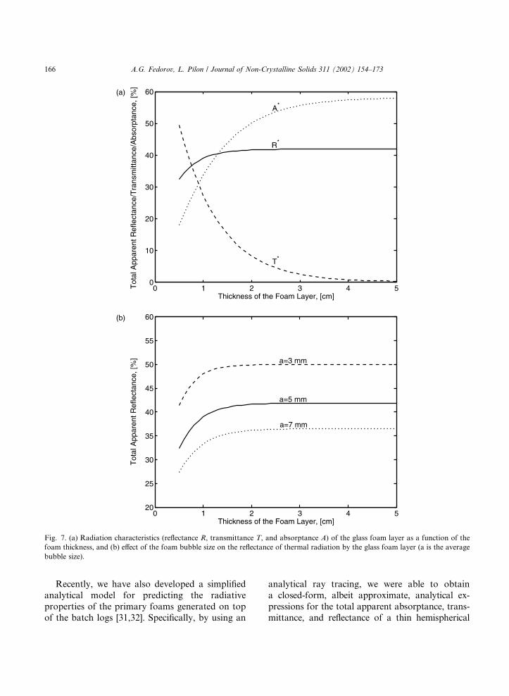
layer [19]. The results of this work (see Figs. 7 and8 for major highlights) confirm Trier�s [6] indirectobservations that the transmittance of thermal
radiation even through a relatively thin (2 cm
thick) foam layer never exceeds 20% or, in other
words, the foam blanket provides significant re-
sistance to radiative heat transfer from the hot
combustion products and refractories to the mol-
ten glass in the tank. We also found that thethickness of the foam layer, the behavior of the
scattering/phase distribution function, bubble size
and shape (spherical vs. polyhedral) distributions
in the foam have major impact on the radiative
characteristics of the foam. It should be also
mentioned that the theoretical predictions of the
total apparent radiation properties of the foam
appear to be in a good agreement with the exper-imental data obtained at Schott Glas, Inc (Mainz,
Germany). 1
Fig. 6. Mass diffusion in isothermal glass foams: concentration
profile across the foam unit cell used to compute the effective
foam diffusion coefficient as a function of the foam porosity for
gases with different thermal solubility parameter (the product of
the solubility S, foam temperature T, and gas constant R) in the
foam lamella.
1 This information has been disclosed to one of the authors
of this paper (AGF) by the members of Schott Glas R&D staff
during his invited seminar presentation on February 8, 2001.
A.G. Fedorov, L. Pilon / Journal of Non-Crystalline Solids 311 (2002) 154–173 165
Recently, we have also developed a simplified
analytical model for predicting the radiative
properties of the primary foams generated on top
of the batch logs [31,32]. Specifically, by using an
analytical ray tracing, we were able to obtain
a closed-form, albeit approximate, analytical ex-
pressions for the total apparent absorptance, trans-
mittance, and reflectance of a thin hemispherical
Fig. 7. (a) Radiation characteristics (reflectance R, transmittance T, and absorptance A) of the glass foam layer as a function of the
foam thickness, and (b) effect of the foam bubble size on the reflectance of thermal radiation by the glass foam layer (a is the average
bubble size).
166 A.G. Fedorov, L. Pilon / Journal of Non-Crystalline Solids 311 (2002) 154–173

semitransparent shell, which is a simple yet real-
istic representation of the unit cell of the pri-
mary foam formed on top of batch logs (see Fig.2(a)). In the case of the large bubble and thick
lamella (as compared to the wavelength of the in-
cident radiation), the numerical ray tracing tech-
nique can be successfully used to predict theabsorption and scattering cross-sections and the
Fig. 8. (a) Effect of the bubble shape on the absorptance A of the foam layer (volume fraction fv ¼ 0:5 corresponds to a foam
consisting of spherical bubbles only; fv ¼ 0:9 corresponds to a foam consisting of polyhedral bubbles only; and fv ¼ 0:7 corresponds to
a foam consisting of 50%: 50% mixture of spherical and polyhedral bubbles); (b) effect of the scattering phase function (i.e., preferred
scattering direction of incident radiation by the foam) on the reflectance R of thermal radiation by the glass foam layer.
A.G. Fedorov, L. Pilon / Journal of Non-Crystalline Solids 311 (2002) 154–173 167

scattering phase function of the foams. Because theincident radiation can be assumed azimuthally
isotropic, the unit cell needs to be discretized only
in a two-dimensional axisymmetric plane and the
radiation intensity field is computed within a two-
dimensional plane only. The incident radiation (I0)is broken into discrete energy bundles of the nor-
malized uniform intensity. In the problem consid-
ered, the bundle trajectory is purely deterministicand, thus, a simple tracing of the energy bundles, as
they travel within the lamella, leads to the same
result as a probabilistic Monte Carlo approach but
without additional computations. Each energy
bundle is traced within the lamella using the re-
flection parameters (i.e., an angle and the reflec-
tivity) computed using Fresnel�s equations until thebundle is absorbed by the substrate (batch) or itsenergy is completely attenuated within the lamella.
The ray tracing algorithm described has been
validated in the case of a thin hemispherical shell
by comparing with an analytical solution of theproblem, and it was shown to be very robust and
capable of producing reliable results [31]. The re-
sults of calculations shown in Fig. 9(a) [32] indi-
cate that the total apparent reflectance and
absorptance of the batch foam can be as large as
15% and 10%, respectively, thereby decreasing the
radiation transmission and batch heating rate to
only about 75% of the total incident radiant en-ergy or even lower. Furthermore, Fig. 9(b) shows
that the scattering phase function of the primary
foams is very well approximated by the commonly
used Henyey–Greenstein (HG) phase function [42,
p. 416].
4.6. Combined conduction and radiation heat trans-
fer in glass foams
The analysis of radiative heat transfer in glass
and batch foams discussed in the previous section
Fig. 9. (a) Comparison of the transmittance of radiation to the batch through a thin planar layer of molten glass on the top of the
batch (no foam case) and in the case when the batch foam is present (modeled as a thin hemispherical shell) as a function of the scaled
lamella thickness (r1=r2) (note that the greater is the radius ratio r1=r2 of the inner to the outer hemispheres defining the foam unit cell,
the thinner is the foam lamella); (b) comparison of the scattering phase function (i.e., preferred direction of for scattering of incident
radiation) of the batch foam with the HG approximation as a function of the cosine of the scattering angle for different scaled foam
lamella thicknesses (r1=r2).
168 A.G. Fedorov, L. Pilon / Journal of Non-Crystalline Solids 311 (2002) 154–173

was instrumental in gaining a critical insight intothe problem, however, a number of assumptions
has been made in the analysis and also several
important features/phenomena unique to glass
foams have been intentionally neglected to sim-
plify the problem formulation, thereby making it
amenable to purely analytical solution. Specifi-
cally: the foam layer was assumed to be isothermal
(i.e., radiation was taken to be the only mode ofheat transfer considered) and �cold� (i.e., self-
emission of radiation was ignored) medium as
compared to the combustion gases in the furnace;
the bubbles in the foam were considered motion-
less; the bubble size distribution function has been
assumed non-uniform but stationary across the
thickness of the foam layer; the shape of the
bubbles (spherical at the bottom and polyhedral atthe top of the layer) has been accounted for only
implicitly through the effective void fraction vari-
ation without explicitly incorporating the bubble
shape effects into the behavior of the scattering
phase function; the dependent scattering effects
have been neglected and the characteristic dimen-
sions of all scatterers were taken to be much larger
than the wavelength of the incident IR radiation;the absorption and scattering cross-sections have
been calculated based on the closed-form albeit
simplified analytical expressions resulted from the
Mie theory in the limit of the weakly absorbing
media.
Although our scaling analysis [19] showed that
many of these assumptions are reasonably accu-
rate as the first approximation, the extent of theirvalidity required more rigorous analysis. More
importantly, despite the dominant role of thermal
radiation in energy transport from the combustion
space to the glass melt, neglecting heat conduction
(due to significant temperature gradient across the
foam layer) and self-emission of thermal radiation
by the foam as well as their intimate coupling and
interaction with radiation heat transfer within thefoam can hardly be justified. To elucidate the im-
portance of these effects, we have performed an
analysis of combined conduction and radiation in
glass foams [33].
Fig. 10(a) shows the temperature distribution
across the foam layer with the characteristics
typically found in glass melting furnaces (called a
�baseline� case) as compared to the idealized foamlayer with the zero resistance to radiative heat
transfer. Clearly, attenuation of thermal radiation
by the foam layer results in a significant decrease
of the rate of heat transfer from the combustion
space to the glass melt and, in turn, in strong re-
duction of the glass surface temperature (by as
much as 500 �C in the case of the 5 cm thick foam
layer). An increase in the thickness of the foamlayer, as shown in Fig. 10(b), not only leads to a
significant decrease in both the heat transfer rate
and the surface temperature of the glass melt, but
also results in an increased temperature of the top
surface of the foam and, thus, in an increased
amount of thermally actuated NOx pollution.
These facts underscore the critical importance of
understanding heat transfer in foams to improve-ment of the glass melting process as well as to
mitigation of its environmental implications.
4.7. Practical solutions for reducing foaming
Given the negative effects of the foam presence
on the energy efficiency, glass quality, furnace
lifetime, and productivity, practical solutions toreduce foaming in glass melting furnaces are
briefly discussed next. In general, batch expansion
or primary foaming can be reduced by inducing
the release of gases before the first liquid phase
appears and becomes interconnected or by accel-
erating the release of gases to the combustion
space [12]. In particular, experimental observa-
tions suggest the following practical measures forlimiting primary foaming:
1. Slow heating of fine silicate grains favors the re-
lease of gases before the liquid phase is formed,
thereby reducing primary foaming [12].
2. Rapid heating of coarse silicate grains shifts the
equilibrium of batch reactions towards higher
temperatures at which the viscosity of the liquidphase is significantly reduced, thereby easing
the escape of gases to the atmosphere [12].
3. Addition of Na2SO4 to the batch limits reten-
tion of gases within the glass melt [1,12]. Kim
and Hrma [10,12,43] suggested several possible
physical mechanisms and theoretical models ex-
plaining such an effect, albeit recognizing that
A.G. Fedorov, L. Pilon / Journal of Non-Crystalline Solids 311 (2002) 154–173 169

none of them is entirely satisfactory. Moreover,
one should note that although Na2SO4 reduces
primary foaming, it also increases secondary
foaming by enhancing refining reactions in the
glass melt. Therefore, the amount of Na2SO4
added to the batch needs to be optimized by
considering both primary and secondary foamformation.
4. A decrease in the pressure of the surrounding
atmosphere reduces the mass of gas retained
in the batch, thereby limiting primary foam for-
mation. However, it also lowers the tempera-
ture at which carbon dioxide is generated in
the batch and thus promotes undesirable batch
expansion [12].
5. The size of the batch particles plays an impor-
tant role in primary foam formation [7,10,43].
The use of finer grains accelerates melting and
also results in higher temperatures at the topof the batch, thereby sealing the top part of
the batch and preventing gases generated at
the bottom from escaping to the atmosphere
[12]. Thus, an increase in the particle size of
the batch powder and of the recycled cullet
Fig. 10. Temperature distribution across the foam layer: (a) comparison of a typical case for combined conduction and radiation heat
transfer against an idealized foam layer with zero resistance to radiative heat transfer for the 5 cm thick foam layer; (b) effect of the
foam thickness on heat transfer in glass foams.
170 A.G. Fedorov, L. Pilon / Journal of Non-Crystalline Solids 311 (2002) 154–173

results in reduction of primary foaming [1].
Ahn and Hrma [8] also showed that compact-
ing and heat treating of the simulated nuclear
waste batch above 1150 �C prior to its intro-
duction into the glass melting furnace limits
significantly the extent of the primary foam.
Finally, retention of gases generated by batch
melting and, in turn, primary foam formationare also reduced by adding melting agents
such as Na2NO3 to the batch and by decreas-
ing the amount of SrCO3 and Al2O3 in the
batch [12].
Various means for reducing secondary foaming
have been studied extensively, particularly when
sodium sulfate Na2SO4 is used as a refining agent[1,11,13,39]. The main findings are the following:
1. An increase in the furnace atmosphere/flame
temperature tends to destabilize the foam [7,9]
with an exponential, Arrhenius type depen-
dence of the foam decay rate on the tempera-
ture [9]. The authors speculate that this effect
is due to the exponential decrease of the glassmelt viscosity as the temperature increases.
2. Kappel et al. [9] observed that an increase in the
pressure and pressure fluctuations of the fur-
nace atmosphere favors decay of the foam,
thereby suggesting the use of ultrasonic waves
to destroy the foam [44].
3. An increase in the SO2 concentration in the
foam bubbles (e.g., provided by the refining re-actions) causes the glass foam to decay faster
[9].
4. Introduction of pulses of reducing gases (e.g.,
CO) to the furnace atmosphere was found to
be an effective way to destroy secondary foams
[1,11]. Thus, as a practical solution, Laimbock
[1] suggested a sudden change from oxidizing
to reducing firing in the combustion space. Thismethod, however, has a number of shortcom-
ings, both environmental and economic (e.g.,
reduced lifetime of refractories) [1].
5. Spraying of oil, natural gas, or any combustible
material as well as Na2SO4, NaOH, and KOH
solutions on top of the secondary foam blanket
was also found to be an efficient way of the
foam destruction [1].
6. In furnaces equipped with oxy-fuel burners, the
amount of refining agents added to the batch
needs to be optimized. Laimbock [1] proposed
a semi-empirical expression for the optimal
amount of sodium sulfate that should be added
to the batch in production of soda-lime silicate
glasses. It accounts for the maximum melting
temperature, the water vapor partial pressurein the combustion space, the batch weight, the
sulfate losses during initial fusion/melting reac-
tions, and the small variations in the batch com-
position [1].
7. Addition of active carbon (e.g., coke) to the
batch reduces secondary foaming occurring in
the high temperature regions of the furnace.
However, it also promotes formation of pri-mary foams [11].
It should be noted that all previously discussed
experimental results were obtained in the labora-
tory crucibles, thus, one should be careful in ex-
tending these results to actual glass melting
furnaces [12]. Some of the more important effects
that are difficult to observe in the small scale lab-oratory systems are as follows: (i) the refining re-
actions observed in crucibles at high temperatures
would most probably occur only at the top of the
batch in the actual furnace that is directly exposed
to radiant heating, whereas the bottom of the
batch is too cold for initiation of fusion reactions
due to the �insulation effect� of the expanded batch;
(ii) partitioning of the gases generated in the batchbetween what is released (escaped) to the com-
bustion space and what is entrapped in the form of
gas bubbles in the glass melt and then carried away
by the convection currents is difficult if not im-
possible to study in laboratory systems.
5. Concluding remarks
This review presents the current state-of-the-art
in understanding and modeling of glass foams in-
cluding mechanisms of formation, foam stability,
transport properties, and heat, mass, and radiation
transfer. Evidently, there has been some progress
made over the years and especially recently in this
area, however, there is still a number of very im-
A.G. Fedorov, L. Pilon / Journal of Non-Crystalline Solids 311 (2002) 154–173 171

portant issues that require further research andsome of them are:
• Understanding and modeling of the processes
defining formation of the primary and second-
ary foams including the retention of gas bubbles
generated within the batch and their partition-
ing between the release to the combustion space
and entrapment within the glass melt. Such amodel should account for the effects of the
batch grain size, the fusion/melting reactions
and CO2 generation, entrapment and escape
of gases generated in the batch, the refining re-
actions, the change of the effective thermal con-
ductivity of the batch due to the presence of
entrapped gases, and the temperature gradients
in the batch.• The effects of the bubble size distribution, the
conditions of the furnace atmosphere (i.e.,
chemical composition, pressure, temperature
and their fluctuations), liquid phase evapora-
tion, and the bubbling gas solubility and diffu-
sivity in the glass melt need to be explored
and quantified in predicting the transient and
steady-state thickness of the foam layer.• Experiment data and mathematical models for
rheological properties of the secondary foams
and their dependence on the foam structure,
chemical composition, and thermophysical
properties are needed for predicting the spread-
ing of the foam over the glass melt surface.
• Development of quantitative models to predict
the minimum superficial gas velocity requiredfor onset of foaming.
• Combined radiation, conduction, and convec-
tion in high temperature batch and glass foams
to account for: (1) emission, absorption, and
scattering of thermal radiation, (2) heat conduc-
tion due to large temperature gradient across
the foam layer, (3) heat convection due to
collective up-rising bubble motion and intra-bubble gas circulation, (4) coupling and interac-
tion effects.
• Effective radiative properties of batch and glass
foams: (1) compare the detailed electromagnetic
calculations with the results of the simplified
model [19] for different sizes of bubbles and
thicknesses of the lamellae; (2) develop an ap-
proach for calculating the scattering phase func-
tion for polyhedral bubbles; (3) explicitly
account for change in the bubble size and shape
distribution functions across the foam thick-
ness; (4) account for the effect of foam stabiliz-
ing surfactants on the effective radiative
properties of the foam; (5) account for the
cross-correlation effects on radiative propertiesdue to collective up-rising motion of bubbles.
• Revisit the question of dependent vs. indepen-
dent scattering by glass foams, considering the
fact the thickness of the foam lamella could be
of the same order of magnitude as the wave-
length of incident radiation and develop the
models for accounting for near-field and multi-
ple scale scattering effects.• Develop a consistent set of experimental data to
verify the predictions of the theoretical models.
In conclusion, we would like to emphasize
a tremendous practical importance of the funda-
mental understanding and experimentally verified
mathematical modeling of glass foams that, com-
bined with comprehensive modeling of the com-bustion space and glass melt in the glass melting
furnace, will provide a foundation for develop-
ment of the energy efficient and environmentally
conscious technology for manufacturing of high
quality glass products.
Acknowledgements
The authors are indebted to the US Department
of Energy and to Argonne National Laboratory
for their financial support within the framework of
the US Department of Energy/Glass Industry/Ar-
gonne National Laboratory/University collabora-tive research project.
References
[1] P.R. Laimbock, PhD thesis, Technical University of
Eindhoven, 1998.
[2] R.G.C. Beerkens, Glastech. Ber. 71 (12) (1995) 369.
[3] S. Kawachi, Y. Kawase, Glastech. Ber. 71 (4) (1998) 83.
[4] S. Kawachi, Y. Kawase, Glastech. Ber. 71 (5) (1998) 111.
[5] R. Viskanta, J. Non-Cryst. Solids 177 (1994) 347.
[6] W. Trier, Glastech. Ber. 36 (3) (1963) 73–86.
172 A.G. Fedorov, L. Pilon / Journal of Non-Crystalline Solids 311 (2002) 154–173

[7] A. Gerrard, I.H. Smith, Laboratory techniques for study-
ing foam formation and stability in glass melting, Glas-
technische Berichte-XIII. Internationaler Glaskongress,
Hamburg, vol. 56K, 4–9 July 1983, p. 13.
[8] J.S. Ahn, P. Hrma, Advances in Ceramics, Nuclear Waste
Management II, vol. 20, 1986, p. 181.
[9] J. Kappel, R. Conradt, H. Scholze, Glastech. Ber. 60 (6)
(1987) 189.
[10] D.-S. Kim, P. Hrma, J. Am. Ceram. Soc. 74 (3) (1991) 551.
[11] R.G.C. Beerkens, P. Laimbock, in: J. Kieffer (Ed.), 60th
Conference on Glass Problems-Urbana, IL, American
Ceramic Society, October 19–20, 1999, p. 41.
[12] D.-S. Kim, P. Hrma, J. Am. Ceram. Soc. 69 (6) (1990)
1039.
[13] R.G.C. Beerkens, L. Zaman, P. Laimbock, S. Kobayashi,
Glastech. Ber. 72 (5) (1999) 127.
[14] R.G.C. Beerkens, H.D. Wall, J. Am. Ceram. Soc. 73 (7)
(1990) 1857.
[15] E. Itoh, H. Yoshikawa, H. Miura, Y. Kawase, Glass
Technol. 38 (4) (1997) 134.
[16] S. Kawachi, M. Kato, Glastech. Ber. 72 (6) (1999) 182.
[17] M. Cable, D. Martlew, Glass Technol. 37 (4) (1996) 137.
[18] L. Nemec, Glass Technol. 21 (3) (1980) 134.
[19] A.G. Fedorov, R. Viskanta, Phys. Chem. Glasses 41 (3)
(2000) 127.
[20] A.G. Fedorov, R. Viskanta, J. Am. Ceram. Soc. 83 (11)
(2000) 2769.
[21] G. Narsimhan, E. Ruckenstein, Lanmuir 2 (1986) 230.
[22] A. Bhakta, E. Ruckenstein, Adv. Colloid Interf. Sci. 70
(1997) 1.
[23] Y. Zhang, R.J. Fruehan, Metall. Mater. Trans. B 26B
(1995) 803.
[24] B. Horan, Foam samples from the techneglas columbus h
furnace, personal communication, 14th June, 2001.
[25] P. Hrma, J. Colloid Interf. Sci. 134 (1) (1990) 161.
[26] R. Viskanta,M.P.Menguc, Appl.Mech.Rev. 42 (1989) 241.
[27] R. Viskanta, X. Wu, Glastech. Ber. 56 (1983) 138.
[28] L. Pilon, A.G. Fedorov, R. Viskanta, J. Cell. Plast. 36
(2000) 451.
[29] L. Pilon, A.G. Fedorov, R. Viskanta, J. Colloid Interf. Sci.
242 (2) (2001) 425.
[30] L. Pilon, A.G. Fedorov, R. Viskanta, Chem. Eng. Sci. 57
(2002) 977.
[31] T.-H. Fan, A.G. Fedorov, J. Quant. Spectrosc. Radiat.
Transfer 73 (2002) 285; Proceedings of the 3rd Interna-
tional Symposium on Radiative Transfer, ICHMT, An-
talya, Turkey, June 17–22, 2001.
[32] T.-H. Fan, A.G. Fedorov, ASME J. Heat Transfer, in
press, in: Proceedings of International Mechanical Engi-
neering Congress & Exposition IMECE�01, ASME, New
York City, NY, November 2001.
[33] M. Varady, A.G. Fedorov, ASME J. Heat Transfer, in
review, Proceedings International Mechanical Engineering
Congress & Exposition IMECE�01, ASME, New York
City, NY, November 2001.
[34] A.G. Fedorov, Proceedings of the 5th ISHMT/ASME
Heat and Mass Transfer Conference, Calcutta, India,
January 2002.
[35] S. Hartland, A.D. Barber, Trans. Institut. Chem. Eng. 52
(1974) 43.
[36] S.A.K. Jeelani, S. Ramaswami, S. Hartland, Trans. Insti-
tut. Chem. Eng., Part A 68 (1990) 271.
[37] C.F. Cooper, J.A. Kitchener, J. Iron Steel Inst. (Septem-
ber) (1959) 48.
[38] M. Cable, C.G. Rasul, J. Savage, Glass Technol. 9 (2)
(1968).
[39] R.G.C. Beerkens, P. Laimbock, Ceram. Eng. Sci. Proc. 21
(1) (2000) 41.
[40] N.M. Parikh, J. Am. Ceram. Soc. 41 (1958) 18.
[41] Geotti-Bianchini, J.T. Brown, A.J. Faber, H. Hessenkem-
per, S. Kobayashi, I.H. Smith, Glastech. Ber. 72 (5) (1999)
145.
[42] M.F. Modest, Radiative Heat Transfer, McGraw-Hill,
New York, NY, 1993.
[43] D.-S. Kim, P. Hrma, J. Am. Ceram. Soc. 75 (11) (1992)
2959.
[44] S.V. Komarov, M. Kuwabara, M. Sano, ISIJ Int. 39 (12)
(1999) 1207.
A.G. Fedorov, L. Pilon / Journal of Non-Crystalline Solids 311 (2002) 154–173 173


![Brazil Glass Foams Produced from Glass and Yerba Mate ... · Yerba mate (Ilex paraguariensis) cultivation [2, 30-33]. Worldwide, the production of yerba mate is significant. Brazil](https://img.dokumen.tips/doc/110x75/5e313ab6d97741746e28a48f/brazil-glass-foams-produced-from-glass-and-yerba-mate-yerba-mate-ilex-paraguariensis.jpg)