Embed Size (px)
Citation preview

USER’S MANUALMANUAL NO. GL500-UM-152
GL500A

Introduction
i
Introduction
Thank you for purchasing the GL500 midi LOGGER dual.Please read this manual thoroughly before attempting to use your new product to ensure that you use itcorrectly and to its full potential.
Notes on Use
Be sure to read all of the following notes before attempting to use the GL500 midi LOGGER dual.
1. Note on the CE Marking
The GL500 complies with the EN61326 (1997+A1:1998+A2:2001 Class A) standard based on the EMCdirective (89/336/EMC). It also conforms to the EN61010-1 (1993/A2:1995) standard based on the LVdirective (72/73/EEC). The AC adapter complies with the EN60950 safety standard.Although the GL500 complies with the above-mentioned standards, be sure to use it correctly in accordancewith the instructions and notes provided in its User's Manual.Moreover, use of the GL500 by incorrect procedures may result in damage to the GL500 or may invalidate itssafeguards. Please confirm all of its notes regarding use and other related information to ensure correct use.
2. Warning
This is a Class A product according to the EMC directive.In a domestic environment, this product may cause radio interference or may be affected by radiointerference to the extent that proper measurement cannot be performed.
3. Notes for Safe Operation
(1) Be sure to use the Graphtec-supplied AC adapter. In environments where there is a lot of noise or wherethe power supply is unstable, we recommend that you ground the GL500.
(2) When a high-voltage signal cable has been connected to the main unit's analog signal input terminal,avoid touching the leads of the input terminal's signal cable to prevent electrical shock due to highvoltage.
(3) Ensure that the GL500's power source is positioned so that it can easily be disconnected.
4. Notes on Functions and Performance
(1) Be sure to connect the main unit to an AC or DC power supply that conforms to the rated range.Connection to a non-rated power supply may cause the main unit to overheat and break down.
(2) Do not block the vents on the main unit.Continued operation with the vents blocked may cause the main unit to overheat and break down.
(3) To avoid malfunctions and other damage, avoid using the GL500 in the following locations.
• Places exposed to high temperature and/or high humidity, such as in direct sunlight or near heatingequipment. (Operating range - Temperature: 0 to 40°C, Humidity: 30 to 80% RH)
• Locations subject to excessive salt spray or heavy fumes from corrosive gas or solvents.
• Excessively dusty locations.
• Locations subject to strong vibrations or shock.
• Locations subject to surge voltages and/or electromagnetic interference.
(4) If the main unit becomes soiled, wipe it off using a soft, dry cloth. Use of organic solvents (such asthinner or benzene) causes deterioration and discoloration of the outer casing.
(5) Do not use the GL500 in the vicinity of other devices which are susceptible to electromagneticinterference.

ii
Introduction
(6) Measured results may not conform to the stated specifications if the GL500 is used in an environmentwhich is subject to strong electromagnetic interference.
(7) Insofar as possible, position the GL500 input signal cables away from any other cables which are likelyto be affected by electromagnetic interference.
(8) For stabilized measurement, allow the GL500 to warm up for at least 30 minutes after turning it on.

To Ensure Safe and Correct Use
iii
To Ensure Safe and Correct Use
• To ensure safe and correct use of the GL500, read this Manual thoroughly before use.
• After having read this Manual, keep it in a handy location for quick reference as needed.
• Do not permit small children to touch the GL500.
• The following describes important points for safe operation. Please be sure to observe them strictly.
Conventions Used in This Manual
To promote safe and accurate use of the GL500 as well as to prevent human injury and property damage,safety precautions provided in this manual are ranked into the five categories described below. Be sure youunderstand the difference between each of the categories.
DANGERThis category provides information that, if ignored, is highly likely to cause fatal or serious injury tothe operator.
WARNINGThis category provides information that, if ignored, is likely to cause fatal or serious injury to theoperator.
CAUTIONThis category provides information that, if ignored, could cause physical damage to the GL500.
HIGH TEMPERATUREThis category provides information that, if ignored, is likely to cause burns or other injury to theoperator due to contact with high temperature.
ELECTRICAL SHOCKThis category provides information that, if ignored, is likely to expose the operator to electricalshock.
Description of Safety Symbols
The symbol indicates information that requires careful attention (which includes warnings).The point requiring attention is described by an illustration or text within or next to the symbol.
The symbol indicates action that is prohibited. Such prohibited action is described by anillustration or text within or next to the symbol.
The symbol indicates action that must be performed. Such imperative action is described by anillustration or text within or next to the symbol.

iv
Safety Precautions
Safety Precautions WARNING
Be sure to securely connect the GL500's power cable.• After checking that the Power switch is turned off, connect the power
cable's female plug to the GL500 and then connect its male plug into theelectrical socket.
• Use of the GL500 without the power cable securely plugged into theelectrical socket may result in electrical shock due to current leakage.
• Before running the GL500 using a DC power supply, be sure to ground theprotective ground terminal ( ) to avoid electrical shock and fire hazards.For grounding, use a ground wire with a diameter of at least 0.75 mm2.When using the GL500 in an environment where grounding is not possible,ensure that the voltage to be measured is no greater than 50 V (DC orrms).
If the GL500 generates smoke, is too hot, emits a strange odor, or otherwise functions abnormally, turn offits power and unplug its power cable from the electrical socket.• Use of the GL500 in such status may result in a fire hazard or electrical
shock.
• After checking that smoke is no longer being generated, contact your salesrepresentative or nearest Graphtec vendor to request repair.
• Never try to perform repair yourself. Repair work by inexperiencedpersonnel is extremely dangerous.
Before turning on the GL500, ensure that the electric socket's supply voltage conforms to the GL500'spower rating.• Use of a different supply voltage may cause damage to the GL500 or a fire
hazard due to electrical shock or current leakage.
Never disassemble or remodel the GL500.• Such action may cause a fire hazard due to electric shock or current
leakage.
• Contact with a high-voltage component inside the GL500 may causeelectric shock.
• If repair is required, contact your sales representative or nearest Graphtecvendor.
Avoid using the GL500 in extremely dusty or humid places.• Such use may cause a fire hazard due to electrical shock or current
leakage.
Securely connect the power cableMake sure that the socket has a goodprotective ground
Use of a differentsupply voltageprohibited
Amateur repairprohibited
No disassembly
Use prohibited
Watch out forelectrical shock

Safety Precautions
v
Safety Precautions WARNING
Avoid using the GL500 in places where it may be exposed to water such as bathrooms, locations exposedto wind and rain, and so on.
Prevent dust or metallic matter from adhering to the power supply connector.• Adhesion of foreign matter may cause a fire hazard due to electrical shock
or current leakage.
Never use a damaged power cable.• Use of a damaged cable may result in a fire hazard due to electrical shock.
• If the cable becomes damaged, order a new one to replace it.
Avoid water
Watch out forelectrical shock
Unplug the powercable from the socket
No foreign matter
Watch out forelectrical shock

vi
Safety Precautions
Safety Precautions CAUTION
Do not use or store the GL500 in a location exposed to direct sunlight or the direct draft of an airconditioner or heater.• Such location may impair the GL500's performance.
Do not place coffee cups or other receptacles containing fluid on the GL500.• Fluid spilling inside the GL500 may cause a fire hazard due to electrical
shock or current leakage.
Do not use the GL500 in a location subject to excessive mechanical vibration or electrical noise.• Such location may impair the GL500's performance.
To insert or disconnect the power cable or a signal input cable, grasp the power cable's plug or the signalinput cable's connector.• Pulling the cable itself damages the cable, resulting in a fire hazard or
electrical shock.
If fluid or foreign matters enters inside the GL500, turn off the Power switch and disconnect the powercable from the electrical socket.• Use in such status may cause a fire hazard due to electrical shock or
current leakage.
• Contact your sales representative or nearest Graphtec vendor to requestrepair.
Do not input a voltage that exceeds the permissible input voltage range that is specified on the GL500'slabel.• Exceeding the specified voltage input range may cause electrical shock or
a fire hazard.
Storage/Use prohibited
Use prohibited
Unplug the powercable from the socket
No pulling
Use prohibited
Avoid fluids
Watch out forelectrical shock

Safety Precautions
vii
Do not attempt to lubricate the GL500's mechanisms.• Such action may cause the GL500 to break down.
Never clean the GL500 using a volatile solvent (such as thinner or benzene).• Such action may impair the GL500's performance.
• Clean off any soiled areas using a soft dry cloth.
Safety Precautions CAUTION
No lubrication
No volatile solvents

viii
Contents
CONTENTS
Introduction ........................................................................................................................................................ iTo Ensure Safe and Correct Use ..................................................................................................................... iii
Conventions Used in This Manual ......................................................................................................... iiiDescription of Safety Symbols ............................................................................................................... iii
Safety Precautions ........................................................................................................................................... iv
1 General Description1.1 Overview ...................................................................................................................................... 1-21.2 Features ...................................................................................................................................... 1-31.3 Operating Environment ................................................................................................................ 1-5
Ambient Operating Conditions ................................................................................................... 1-5Warming-up Before Use ............................................................................................................ 1-5Configuration When in Use ........................................................................................................ 1-5
1.4 Notes on Temperature Measurement .......................................................................................... 1-61.5 Notes on Using the Monitor ......................................................................................................... 1-61.6 Changing the Display Language ................................................................................................. 1-6
2 Checks and Preparation2.1 Checking the Outer Casing.......................................................................................................... 2-22.2 Checking the Accessories............................................................................................................ 2-22.3 GL500 Part Names and Functions .............................................................................................. 2-32.4 Monitor Part Names and Functions ............................................................................................. 2-42.5 Control Panel Key Names and Functions .................................................................................... 2-62.6 Connecting to a PC ..................................................................................................................... 2-8
Connection Using a LAN Cable ................................................................................................. 2-8Connection using a USB Cable ................................................................................................. 2-8
2.7 Connecting the Power Cable and Turning on the Power .............................................................. 2-9Connecting to an AC Power Supply ........................................................................................... 2-9Connecting to a DC Power Supply .......................................................................................... 2-10
2.8 Using the Battery Pack (Option) ................................................................................................ 2-11Mounting the Battery Pack....................................................................................................... 2-11Charging the Battery................................................................................................................ 2-12
2.9 Inserting and Removing a PCMCIA Card .................................................................................. 2-13Inserting a PCMCIA Card ........................................................................................................ 2-13Removing a PCMCIA Card ...................................................................................................... 2-13
2.10 Mounting and Removing the Input Terminal Unit ....................................................................... 2-14Mounting the Input Terminal Unit ............................................................................................. 2-14Removing the Input Terminal Unit ............................................................................................ 2-14
2.11 Connecting the Signal Input Cables to the Input Terminal Unit ................................................. 2-154VF Input Terminal Unit ........................................................................................................... 2-154MF Input Terminal Unit ........................................................................................................... 2-168MS Input Terminal Unit .......................................................................................................... 2-17
2.12 Noise Countermeasures ............................................................................................................ 2-182.13 Logic or Pulse Input/Alarm Output Functions ............................................................................ 2-192.14 External Trigger Functions ......................................................................................................... 2-202.15 Setting the Date and Time ......................................................................................................... 2-21

Contents
ix
How to Charge the Rechargeable Battery ............................................................................... 2-21How to Set the Date and Time ................................................................................................. 2-21
3 Settings and Measurement3.1 Descriptions of Control Keys (Setting / Capturing) ...................................................................... 3-2
1. CH GROUP key ..................................................................................................................... 3-22. RANGE/SPAN/POSITION key............................................................................................... 3-33. TIME/DIV key......................................................................................................................... 3-44. START/STOP key .................................................................................................................. 3-45. Direction keys ........................................................................................................................ 3-56. DISPLAY key ......................................................................................................................... 3-57. REVIEW key .......................................................................................................................... 3-58. SAVE key ............................................................................................................................... 3-69. CURSOR key ......................................................................................................................... 3-610.QUIT key ............................................................................................................................... 3-611.MENU key ............................................................................................................................. 3-6
3.2 Setting Procedures ...................................................................................................................... 3-73.3 Description of Basic Setting Menu (Setting) ................................................................................ 3-7
MENU key .................................................................................................................................. 3-7q AMP Settings .................................................................................................................... 3-8w CRNT Settings ................................................................................................................ 3-13e EVNT Settings ................................................................................................................ 3-18r CALC Settings ................................................................................................................ 3-21t FILE Settings .................................................................................................................. 3-22y I/F Settings ...................................................................................................................... 3-24u OTHR Settings ................................................................................................................ 3-25i INFO Display ................................................................................................................... 3-27
3.4 Data Replay ............................................................................................................................... 3-28Data Replay ......................................................................................................................... 3-28Readout Menu ..................................................................................................................... 3-34
4 Software4.1 System Requirements ................................................................................................................. 4-24.2 Installing the USB Driver.............................................................................................................. 4-3
Checking the version of your USB driver ................................................................................... 4-3Installing the USB Driver ........................................................................................................... 4-4
4.3 Connecting to a PC ..................................................................................................................... 4-6Connection Using a LAN Cable ................................................................................................. 4-6Connection Using a USB Cable ................................................................................................ 4-6
4.4 Installing the GL500 Application Software ................................................................................... 4-74.5 Setting the IP Address and Device ID.......................................................................................... 4-84.6 Menu Configuration and System Settings ................................................................................... 4-9
Starting the Application Software .............................................................................................. 4-94.7 PC Connection Settings ............................................................................................................ 4-124.8 Application Software Measurement Example ............................................................................ 4-13
1. Connecting to Your PC ........................................................................................................ 4-132. Inputting Signals .................................................................................................................. 4-133. Launching the Application Software..................................................................................... 4-134. Setting the Parameters ........................................................................................................ 4-14

x
Contents
5. Capturing Input Data ............................................................................................................ 4-166. Replaying Data .................................................................................................................... 4-187. Exiting the Application Software .......................................................................................... 4-19
4.9 Measurement Parameter Settings ............................................................................................. 4-20AMP ......................................................................................................................................... 4-20Current ..................................................................................................................................... 4-22Event ....................................................................................................................................... 4-25File ........................................................................................................................................... 4-28Scaling ..................................................................................................................................... 4-30Arithmetic, XY, FFT .................................................................................................................. 4-31Other ........................................................................................................................................ 4-33Information ............................................................................................................................... 4-34
4.10 View Functions .......................................................................................................................... 4-35Data Capture Start/Stop .......................................................................................................... 4-35GL400/350 ............................................................................................................................... 4-36GL500 + GL400/350 ................................................................................................................ 4-38Y-T ........................................................................................................................................... 4-39Digital View .............................................................................................................................. 4-40X-Y ........................................................................................................................................... 4-41FFT .......................................................................................................................................... 4-41Calculation ............................................................................................................................... 4-42
4.11 Review Device ........................................................................................................................... 4-43Opening a File ......................................................................................................................... 4-43Superimpose ........................................................................................................................... 4-45Convert then Save ................................................................................................................... 4-46Display in Excel ....................................................................................................................... 4-47Print ......................................................................................................................................... 4-47
4.12 Review PC ................................................................................................................................. 4-48Opening a File ......................................................................................................................... 4-49Superimpose ........................................................................................................................... 4-51Convert then Save ................................................................................................................... 4-52Display in Excel ....................................................................................................................... 4-52Print ......................................................................................................................................... 4-52
4.13 Logic, Alarm Display .................................................................................................................. 4-53
5 Specifications5.1 Standard Specifications ............................................................................................................... 5-2
Standard Specifications ............................................................................................................. 5-2Internal Memory Devices ........................................................................................................... 5-3PC Interface ............................................................................................................................... 5-3Monitor ....................................................................................................................................... 5-3Input Unit Specifications (4VF) .................................................................................................. 5-4Input Unit Specifications (4MF) ................................................................................................. 5-5Input Unit Specifications (8MS) ................................................................................................. 5-6
5.2 Function Specifications ................................................................................................................ 5-7Function Types .......................................................................................................................... 5-7Trigger Functions (Current) ....................................................................................................... 5-7Trigger Functions (Event) .......................................................................................................... 5-7External Input/Output Functions ................................................................................................ 5-8

Contents
xi
5.3 Accessory/Option Specifications ................................................................................................. 5-9Control Software ........................................................................................................................ 5-9Battery Pack (Option) ................................................................................................................ 5-9
5.4 External Dimensions .................................................................................................................. 5-10
Index .............................................................................................................................................................. I-1

This chapter provides a general description of theGL500 and its features.
CHAPTER 1General Description
1.1 Overview1.2 Features1.3 Operating Environment1.4 Notes on Temperature Measurement1.5 Notes on Using the Monitor1.6 Changing the Display Language

1-2
General Description
1.1 Overview
The GL500 is capable of faithful measurement of sudden events, both low- and high-speed, whilesimultaneously performing data capture or long-term measurement. It is a compact, lightweight data loggerthat comes equipped with a large color display monitor and built-in memory, and can be connected to a PCvia a USB or LAN cable to enable on-line settings, measurement, and data capture.

General Description
1-3
1.2 Features
A5-size Device Capable of Handling Mixed-signal Isolated and Non-isolated InputsThe compact A5-size body enables easy portability. Three types of input terminal units are provided: anisolated voltage input terminal unit, an isolated voltage/temperature input terminal unit, and a non-isolatedvoltage/temperature input terminal unit. Select one unit or a combination of units to suit your measurementapplication. The units can be easily installed and removed using a one-touch operation, and they can becombined to increase the number of channels up to a maximum of 16. In addition, the multifunction inputcapability enables the handling of both logic and pulse signals. An alarm output function is also provided.
Note: Please consult your sales representative or nearest Graphtec vendor for more information on combiningand increasing the number of input terminal units.
CAT I 10Vp–p max.
3 41 2 3 41 21 2 1 2
CAT I 100Vp–p max.Ranges Up to 10V :30Vp–p max.
30VAC rms(60VDC max.)
CAT I 100Vp–p max.Ranges Up to 10V :30Vp–p max.
30VAC rms(60VDC max.)
1 2 3 4
Isolated voltage input terminal unit
Isolated voltage/temperature input terminal unit
Non-isolated voltage/temperature input terminal unit
One-touch installation and removalMax. 16 channels
Can be freely combined
Dual High-speed and Low-speed SamplingIf an unexpected event occurs during measurement at low-speed sampling (max. 1 ms), that part of the datacan be measured at high-speed sampling (max. 2µs) at a high definition. 4 MB of memory are provided forcurrent data, and 32 MB for event data. In addition, since a PCMCIA card slot is also built in, large volumesof data can be captured to these memory storage devices.
• Low-speed sampling data : current data• High-speed sampling data : event data
Low-speed sampling data For current dataData is captured to the 4-MB internal memory or to a PCMCIA card.
High-speed sampling data For event dataData is captured to the 32-MB internal
memory
When limited to 1 ch
4-MB internal memory
64-MB PCMCIA card
Approx. 6.4 seconds
Approx. 16 seconds
Approx. 32 seconds
Approx. 1 minute
Approx. 53 minutes
Approx. 13 seconds
Approx. 26 seconds
Approx. 53 seconds
Approx. 44 minutes
Approx. 20 seconds
Approx. 40 seconds
Approx. 33 minutes
Approx. 26 seconds
Approx. 22 minutes
2µs 5µs 10µs 20µs 1ms
When limited to 2 chWhen limited to 4 chWhen limited to 8 ch
High-speed sampling data capture times
Low-speed sampling data capture times
Approx. 3 minutes
Approx. 53 minutes
Approx. 5 hours
Approx. 3 days
Approx. 23 days
1ms 100ms 10s
Approx. 370 daysDa
ta c
aptu
re
cond
ition
s

1-4
General Description
USB Drive ModeThe USB drive function allows a PC to recognize a PC card inserted into the GL500as an external drive. The USB drive mode function is enabled by connecting theGL500 to a PC,and then pressing the START key to turn on the GL500.
Dedicated Pursuit of Ease of UseCursor keys have been used to enable user-friendly operation using only thefingertips, in the same way as a mobile phone is used. Even first-time users caneasily follow the step-by-step setting menus to perform setups and checkmeasurement data on the easy-to-read data displays. Event data that occurred duringmeasurement can be reviewed together with the current data on dual stackedscreens. Moreover, since the application software screens are similar in appearanceto those of the GL500 screens, they can be used intuitively, in the same manner.Waveform and digital data screens can be displayed at the same time.
• Cursor Keys Used for Effortless OperationOperation similar to that of a mobile phone has been realized.User-friendly operation using just the fingertips
• Worry-free Battery Charging during Normal UseBattery charging can be performed even during measurement. In the same way as with a notebookcomputer, the battery drive can be used whenever you like, making this a convenient function when youwant to use the device quickly for measurement outdoors.The time required for charging depends on the temperature. Charging is performed after the temperaturehas been monitored. Depending on the length of continuous use, there may be times when the internaltemperature rises and battery charging stops. After the power supply is turned off and the internaltemperature drops, battery charging is restarted.
Simple, High-speed Connection to a PCThe built-in USB 2.0 interface enables easy connection to a personal computer. Data can be easilytransferred at a high-speed 1-ms rate. Moreover, remote measurement via the LAN connection and datatransfer using a PCMCIA card are also enabled.Simple setups and easy-to-read data displays facilitate computer operation, and current data can bedisplayed in real time up to the maximum 1-ms sampling speed. Moreover, the application software enablesunexpected events that occur during measurement to be captured as event data. The event data that youwant to check can be displayed together with the current data on dual stacked screens.
PCMCIA card
Offline data transfer
LAN: Remote measurement
USB: Easy connection
CH GROUP RANGE/SPANPOSITION
TIME/DIV
QUIT MENU
LOCAL
ENTER
DISPLAY
SAVE
REVIEW
STARTSTOP
CURSOR

General Description
1-5
1.3 Operating Environment
This section explains the operating environment for the GL500.
Ambient Operating Conditions
(1) Ambient temperature and humidity (the GL500 must be operated within the following ranges.)
• Temperature range: 0 to 40°C (15 to 30°C when using the battery)
• Humidity range: 30 to 80% RH
(2) Environment (do not use in the following locations.)
• Locations in direct sunlight or with high humidity, such as near heaters
• Locations exposed to salty air, corrosive gases, or organic solvents
• Dusty locations
• Locations subject to vibration or impact
• Locations subject to voltage surge or electromagnetic interference such as lightning orelectric furnaces
(3) Installation category (over-voltage category)
• The GL500 conforms to the IEC664 installation category I.
CHECKPOINTIf condensation occurs...Condensation occurs in the form of water droplets on the device surfaces and interior when the GL500is moved from a cold to a warm location. Using the GL500 with condensation present will causemalfunctioning. Wait until the condensation has disappeared before turning on the power.
Warming-up Before Use
The GL500 should be allowed to warm up with the power turned on for approximately 30 minutesto ensure that it operates according to the specified performance.
Configuration When in Use
Do not use the GL500 standing upright or at an angle. It must always be laid flat.Usage Configuration: Flat
CAUTIONDo not block the air vents on the GL500, as this will cause malfunctioning.

1-6
General Description
1.4 Notes on Temperature Measurement
Please observe the following precautions when performing temperature measurement.
(1) Do not block the air vents. Always provide a space of at least 30 cm on all sides of the GL500.
(2) For stabilized temperature measurement, allow the GL500 to warm up for at least 30 minutesafter turning it on.
(3) Exposure of the input terminals to direct drafts, direct sunlight, or abrupt changes intemperature may impair the equilibrium of the input parts and result in measurement errors. Tomeasure temperature in such an environment, take appropriate countermeasures such aschanging the installation site of the GL500.
1.5 Notes on Using the Monitor
The monitor is an LCD display unit, and so the display will vary depending on the operating environment.
CHECKPOINTIf the screen saver function is used, it will operate and clear the screen if no operations are performedduring the preset time. If the screen saver operates, press any key to restore the display.
CAUTION• Condensation may form on the LCD screen if the GL500 is moved from a cold to a warm location. If
this occurs, wait until the LCD screen warms up to room temperature.
• The LCD screen is manufactured to extremely high precision. Black dots may appear, or red, blue,and green dots may not disappear. Likewise, streaks may appear when viewed from certain angles.These phenomena are due to the LCD screen construction, and are not signs of a fault.
1.6 Changing the Display Language
You can choose English, French, or Japanese as the language displayed on the screen. The default displaylanguage is set to English (US) when the GL500 is shipped overseas. To change the display language,perform the (Language) settings described on page 3-25.

This chapter explains how to check the GL500's external casing andaccessories, and how to prepare the GL500 for operation.
CHAPTER 2Checks and Preparation
2.1 Checking the Outer Casing2.2 Checking the Accessories2.3 GL500 Part Names and Functions2.4 Monitor Part Names and Functions2.5 Control Panel Key Names and Functions2.6 Connecting to a PC2.7 Connecting the Power Cable and Turning on the Power2.8 Using the Battery Pack (Option)2.9 Inserting and Removing a PCMCIA Card2.10 Mounting and Removing the Input Terminal Unit2.11 Connecting the Signal Input Cables to the Input Terminal Unit2.12 Noise Countermeasures2.13 Logic or Pulse Input/Alarm Output Functions2.14 External Trigger Functions2.15 Setting the Date and Time

2-2
Checks and Preparation
2.1 Checking the Outer Casing
After unpacking, check the GL500's outer casing before use. In particular, please check for the following:
• Surface scratches• Other flaws such as stains or dirt
2.2 Checking the Accessories
After unpacking, check that the following standard accessories are included. The accessories included willdiffer depending on the model purchased.
Standard Accessories
Optional Accessories
Item Remarks QuantityQuick Start Guide GL500-UM-851 1CD-ROM User's Manual, Application software 1LCD protector For protecting the LCD surface 1AC cable/AC adapter 100 to 240 VAC, 50/60 Hz 1Core Must be attached when the GL500 is used in the EU region 1Screwdriver for input terminal unit Fits inside the main unit 1
Item Option No. Remarks4VF input terminal unit 4VF Input terminals for 4 channels (can be mounted in the main unit)4MF input terminal unit 4MF Input terminals for 4 channels (can be mounted in the main unit)8MS input terminal unit 8MS Input terminals for 8 channels (can be mounted in the main unit)Battery pack B-517Logic/alarm cable B-513 Bare tips (2-m length)DC drive cable B-514 Bare tips (2-m length)BNC-BNC cable RIC-112 1.5-m lengthBNC-Banana clip cable RIC-113 1.5-m lengthBNC-Alligator clip cable RIC-114 1.5-m length

Checks and Preparation
2-3
2.3 GL500 Part Names and Functions
This section describes the names and functions of parts of the GL500.
Top panel
Bottom panel
(4) Monitor
(12) Input terminal unit 1
(12) Input terminal unit 2
(17) Screwdriver for use with the input terminal units
(5) Control panel keys
(6) Power connector
(1) Power LED
(2) Data capture LED (3) Battery charging LED
(7) Power switch
(13) USB connector terminal(14) LAN connector terminal
(15) Monitor control dial
(8) PCMCIA slot(9) Logic or Pulse input/alarm output terminal
Not used
(10) GND terminal
(11) External trigger terminal
Not used
(16) Battery
(1) Power LED ..........................This LED is lit when the power switch is in the 'On' status.
(2) Data capture LED ................This LED is lit while data is being captured.
(3) Battery charging LED ..........This LED is lit when the battery is being charged.
(4) Monitor ................................Displays the setting menus and measurement data.
(5) Control panel keys...............Used for the main operations, including settings, and starting andstopping measurement.
(6) Power connector .................Terminal for connecting the AC/DC power cables.
(7) Power switch .......................Switch for turning on the power.
(8) PCMCIA slot ........................Used for inserting the PCMCIA card (PC card).
(9) Logic or Pulse input/alarm output terminal.............................Used for logic or pulse input and alarm output.
(10) GND terminal .....................Connects the main unit to ground.
(11) External trigger terminal ....Terminal for the input of external triggers.(12) Input terminal units 1 & 2...Used to connect the 4VF, 4MF, and 8MS input terminal units.(13) USB connector terminal ....Terminal for connecting the USB cable.
(14) LAN connector terminal .....Terminal for connecting the LAN cable.
(15) Monitor control dial ............Used to adjust the monitor contrast.
(16) Battery ...............................Backup battery used in the case of an AC or DC power failure.
(17) Screwdriver for use with the input terminal units.............................Used to connect the signal input cables to the input terminal units.
Note: Attach the LCD protector to the surface of the LCD display when you want to protect it.

2-4
Checks and Preparation
2.4 Monitor Part Names and Functions
This section describes the monitor unit on top of the GL500.
(2) Simplified message display area
(1) Processing mode display area (3) Time/Div display area
(5) Key lock
(8) Battery drive
(6) Remote
(7) AC drive
(9) Date/Time display area(10) Alarm display area
(11) Analog signal monitor area
(12) Logic/Pulse settings display area
(13) Memory block capture display area
(15) Waveform/settings window display area
(14) Pen display
(17) Scale upper limit
(16) Event data display
(17) Scale lower limit
(18) Memory/PCMCIA display area
(4) PCMCIA card access display
(1) Processing mode display area.............................Displays the processing mode currently set.
(2) Simplified message display area.............................Displays the system status. ("Free Running") is usually displayed.
For example, "Armed" is displayed when waiting for a trigger signal.
(3) Time/Div display area ..........Displays the current time scale.
(4) PCMCIA card access display.............................The red LED flashes while data on the PCMCIA card is being
accessed.
(5) Key lock ...............................Lit when the GL500 is in key lock status. To enable key lock status,hold down the two [ ] and [ ] keys for at least three seconds.
(6) Remote ................................Lit when the GL500 is in remote status.
(7) AC drive ...............................Lit when the AC power supply is being used.
(8) Battery drive ........................Lit when the battery is being used.
(9) Date/Time display area .......Displays the current date and time.
(10) Alarm display area .............Displays the alarm outputs.
(11) Analog signal monitor area.............................Displays the input signal values for each channel.
(12) Logic/Pulse settings display area.............................Logic : Displays the operation status.
Pulse: Displays the measured values.(Display switching: Off, Logic, Pulse)
(13) Memory block capture display area.............................Different colors are used to indicate the status of the data captured
to memory.
(14) Pen display ........................Pens are displayed for each group.

Checks and Preparation
2-5
(15) Waveform/settings window display area.............................Displays the measurement signal waveforms. The menu windows
are also displayed when the condition setting keys are pressed.
(16) Event data display .............Displays the event data capture status.
(17) Scale upper/lower limit ......Displays the measurement scale for the range set.
(18) Memory/PCMCIA display area.............................Displays the capture status of the current data (memory and
PCMCIA).

2-6
Checks and Preparation
2.5 Control Panel Key Names and Functions
This section describes the control panel keys.See Section 3.1 ”Description of Control Keys (Setting/Capturing)” and 3.4 “Data Replay” for furtherinformation.
CH GROUP RANGE/SPANPOSITION
TIME/DIV
QUIT MENU
LOCAL
ENTER
DISPLAY
SAVE
REVIEW
STARTSTOP
CURSOR
(1) CH GROUP key(2) RANGE/SPAN/POSITION key
(3) TIME/DIV key
(5) MENU key(4) QUIT key
(8) DISPLAY key
(9) SAVE key(12) START/STOP key
(10) REVIEW key
(7) Direction keys(6) ENTER key
(11) CURSOR key
(1) CH GROUP key ..................Switches between channel groups.
(2) RANGE/SPAN/POSITION key..................................................Switches through the INPUT, RANGE, SPAN, and POSITION
settings on the monitor display. These settings can be specified foreach channel. * It switches through the TRACE/SPAN/POSITION displaysduring replay.
(3) TIME/DIV key ......................Used to switch the time axes.
(4) QUIT key .............................Used to cancel the displayed setting item.Also used to close the Data Review Display.Also used to cancel the REMOTE status.
(5) MENU key ...........................Switches through the various setting menus.
(6) ENTER key ..........................Enters the details set in the current setting window.A waveform search can be made from Current to Event, and Eventto Current in the 2-screen view mode.
(7) Direction keys ( ) ........These keys move the cursor on the screen in the directionindicated.
Direction keys ( ) .......Use these keys to scroll the memory data waveforms and movethe cursor. Hold down both keys together for at least three secondsto enable key lock status. To cancel key lock status, press themagain for at least three seconds.
(8) DISPLAY key .......................Switches through the Waveform, Enlarged Waveform, and DigitalData screens.It switches effective screens between Current and Event in the 2-screen view mode.

Checks and Preparation
2-7
(9) SAVE key.............................Used to save memory data and make a copy of the displayedscreen.
(10) REVIEW key ......................Replays the captured data.It switches “2-screen to 1-screen”, or “1-screen to 2-screen” during2-screen replay.
(11) CURSOR key ....................Press the CURSOR key to switch between Cursor A and B.
(12) START/STOP key ..............Press this key to start measurement or to stop measurement whenmeasurement is in progress.

2-8
Checks and Preparation
2.6 Connecting to a PC
The GL500 can be connected to a PC via a LAN cable or a USB cable.
Connection Using a LAN Cable
Use the LAN cable to connect the GL500 to a PC.
LAN cable
Connection using a USB Cable
Use the USB cable to connect the GL500 to a PC.
USB cable
CHECKPOINTIf the USB cable is used, the USB driver must be installed in your PC. See Section 4.2, "Installing theUSB Driver", for the installation procedure.
Checks and Preparation
2-9
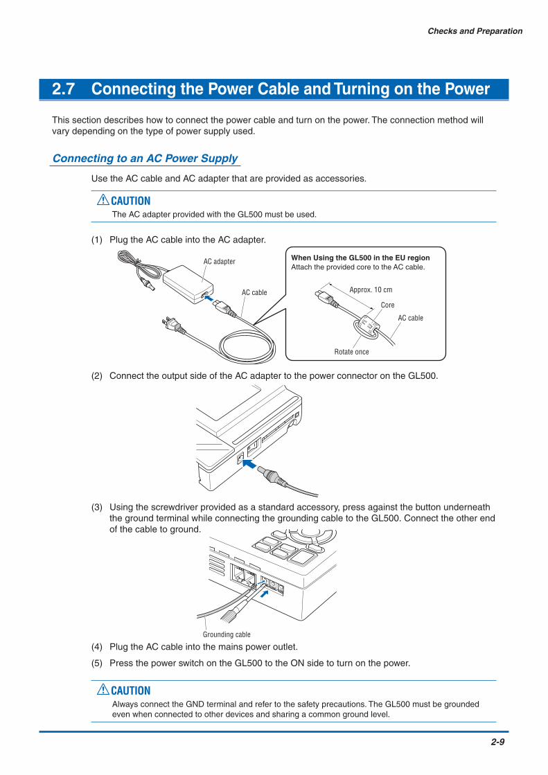
2.7 Connecting the Power Cable and Turning on the Power
This section describes how to connect the power cable and turn on the power. The connection method willvary depending on the type of power supply used.
Connecting to an AC Power Supply
Use the AC cable and AC adapter that are provided as accessories.
CAUTIONThe AC adapter provided with the GL500 must be used.
(1) Plug the AC cable into the AC adapter.
AC adapter
AC cable Approx. 10 cm
Core
AC cable
Rotate once
When Using the GL500 in the EU regionAttach the provided core to the AC cable.
(2) Connect the output side of the AC adapter to the power connector on the GL500.
(3) Using the screwdriver provided as a standard accessory, press against the button underneaththe ground terminal while connecting the grounding cable to the GL500. Connect the other endof the cable to ground.
Grounding cable
(4) Plug the AC cable into the mains power outlet.
(5) Press the power switch on the GL500 to the ON side to turn on the power.
CAUTIONAlways connect the GND terminal and refer to the safety precautions. The GL500 must be groundedeven when connected to other devices and sharing a common ground level.

2-10
Checks and Preparation
Connecting to a DC Power Supply
Use the optional DC drive cable (B-514).
CAUTION• Use a power supply within the 8.5 to 24 VDC range.
• The B-514 DC drive cable must be used.
(1) Configure the tip of the DC drive cable (B-514, 2-m length) to enable it to be connected to theDC power supply.
(2) Connect the DC input side of the DC drive cable to the DC power supply.
CAUTIONBe sure to check the polarity of the wire tips when performing wiring.
(3) Connect the DC output side to the power connector on the GL500.
B-514(8.5 to 24 VDC power supply)
Shielded lead (– side)
White (+ side)
(4) Press the power switch on the GL500 to the ON side to turn on the power.

Checks and Preparation
2-11
2.8 Using the Battery Pack (Option)
Use the battery pack for data back-up when the AC power supply is interrupted by a power failure orbrownout. For the expected operating time when using the battery pack, see Section 5.3, "Accessory/OptionSpecifications".
Mounting the Battery Pack
(1) Use a screwdriver to remove the battery pack cover from the bottom panel.
(2) Mount the battery pack in the direction shown by the arrow.Battery pack
(3) Reattach the cover, and fasten the screw in place.
CAUTIONDo not use the GL500 without the cover fastened in place.

2-12
Checks and Preparation
Charging the Battery
Expected time required for chargingWhen using the GL500 for charging: Approx. 4 hours (when the power supply is OFF)
Using the GL500 for Charging
The battery pack is charged by mounting it in the GL500, and supplying it with AC power. Thebattery cannot be charged, however, if the internal temperature has risen during continuousoperation.
(1) Mount the battery pack in the GL500 (see the previous section for the mounting procedure).
(2) Turn on the power to the GL500. (See Section 2.7, "Connecting the Power Cable and Turningon the Power").
Power LED
Battery charging LED
CHECKPOINT• If battery charging is attempted while the GL500 is being used continuously or immediately
afterwards, charging may not be performed. However, charging will start automatically as soon as theGL500 has cooled down.
• If input is being made directly from the DC power supply instead of the AC adapter, the DC voltagemust be at least 16V.

Checks and Preparation
2-13
2.9 Inserting and Removing a PCMCIA Card
This section describes how to insert and remove a PCMCIA card.
CAUTION• Adequate precautions against static electricity must be taken when handling PCMCIA cards.
• Do not remove the PCMCIA card if the PCMCIA card access display on the monitor is flashing red. Data loss ormalfunctions may occur.
Inserting a PCMCIA Card
Insert the PCMCIA card into the slot as far as it will go.
Removing a PCMCIA Card
Press the eject button next to the PCMCIA card slot so that the button protrudes. Press it oncemore to eject the PCMCIA card.
Press
Press once more

2-14
Checks and Preparation
2.10 Mounting and Removing the Input Terminal Unit
This section describes how to mount and remove the input terminal unit.
CAUTION• Make sure that the power supply has been turned off before mounting or removing the input terminal unit.
• The input terminal units that can be used are the 4VF, 4MF, and 8MS units. Input terminal units for the GL400model cannot be used with the GL500.
Mounting the Input Terminal Unit
(1) Remove the cover from the input terminal mounting area.
(2) As shown in the figure below, insert the input terminal unit in the GL500. At this time, be sure tocheck that the input terminal unit is locked onto the connector.
Removing the Input Terminal Unit
(1) Remove the cover from the input terminal mounting area.
(2) Press down on the lock button while pulling the input terminal unit towards you. At this time,grip the input terminal unit firmly while removing it.
(3) Replace the cover for the input terminal mounting area.

Checks and Preparation
2-15
2.11 Connecting the Signal Input Cables to the Input Terminal Unit
This section describes how to connect the signal input cables to the input terminal unit.
4VF Input Terminal Unit
This is a 4-channel isolated voltage input terminal unit.
CHECKPOINTThis input terminal unit is for use with the GL500 model only. Do not mount input terminal units for othermodels such as the GL400 in the GL500.
Terminal Configuration and Input Signal Types
CAT I 100Vp–p max.Ranges Up to 10V :30Vp–p max.
30VAC rms(60VDC max.)
1 2 3 4
High-voltage input terminal
Low-voltage input terminal
+ ................................................High-voltage terminal (terminal for high-voltage input signals)
– ................................................Low-voltage terminal (terminal for low-voltage input signals)
Item DescriptionInput configuration Isolated input for each channel, scanning method, unbalanced inputInput terminal BNC connectorAnalog voltage 100, 500 mV/FS; 1, 5, 10, 50, 100 V/FSSampling interval*1 Current: 1 to 500 ms; 1 to 30 s; 1 to 30 min; 1 h
Event: 2 to 500 µs; 1 to 500 ms; 1 sA/D resolution 14-bitFrequency characteristic DC coupling: DC to 20 kHz (+1/–3dB Typ)Permissible input voltage Between + and – terminals: 50 to 100 V range: 100 Vp-p max.
100 mV to 10V range: 30 Vp-p max.Between input terminals and GND: 30 VAC rms, 60 VDC max.
Filter Off, Line, 5, 50, 500 Hz
*1 The maximum sampling interval will depend on the number of channels being used.

2-16
Checks and Preparation
4MF Input Terminal Unit
This is a 4-channel isolated voltage and temperature input terminal unit.
CHECKPOINTThis input terminal unit is for use with the GL500 model only. Do not mount input terminal units for othermodels such as the GL400 in the GL500.
Terminal Configuration and Input Signal Types
1 2 1 2
CAT I 100Vp–p max.Ranges Up to 10V :30Vp–p max.
30VAC rms(60VDC max.)
+ –
Voltage
+ –
Thermocouple
Signal ground
Use the provided screwdriver to loosen the terminal screws. Insert the cables in the terminals, andthen tighten the screws to hold the cables in place.
+ ................................................High-voltage terminal (terminal for high-voltage input signals)
– ................................................Low-voltage terminal (terminal for low-voltage input signals)
Item DescriptionInput configuration Isolated input for each channel, scanning method, unbalanced inputAnalog voltage 100, 500 mV/FS; 1, 5, 10, 50, 100 V/FSThermocouples K, J, E, T, R, S, B, N, W (WRe 5-26)Sampling interval*1 Current: 1 to 500 ms; 1 to 30 s; 1 to 30 min; 1 h
Event: 2 to 500 µs; 1 to 500 ms; 1 sA/D resolution 14-bitFrequency characteristic DC coupling: DC to 20 kHz (+1/–3dB Typ)Permissible input voltage Between + and – terminals: 50 to 100 V range: 100 Vp-p max.
100 mV to 10V range: 30 Vp-p max.Between input terminals and GND: 30 VAC rms, 60 VDC max.
Filter Off, Line, 5, 50, 500 Hz
*1 The maximum sampling interval will depend on the number of channels being used.

Checks and Preparation
2-17
8MS Input Terminal Unit
This is an 8-channel non-isolated voltage and temperature input terminal unit.
CHECKPOINTThis input terminal unit is for use with the GL500 model only. Do not mount input terminal units for othermodels such as the GL400 in the GL500.
Terminal Configuration and Input Signal Types
CAT I 10Vp–p max.
3 41 2 3 41 2
+ –
Voltage
+ –
Thermocouple
Signal ground
Use the provided screwdriver to loosen the terminal screws. Insert the cables in the terminals, andthen tighten the screws to hold the cables in place.
+ ......................................... High-voltage terminal (terminal for high-voltage input signals)
–.......................................... Low-voltage terminal (terminal for low-voltage input signals)
Item DescriptionInput configuration Isolated input for each channel, scanning method, balanced inputAnalog voltage 100, 500 mV/FS; 1, 5, 10 V/FSThermocouples K, J, E, T, R, S, B, N, W (WRe 5-26)Sampling interval*1 Current: 1 to 500 ms; 1 to 30 s; 1 to 30 min; 1 h
Event: 2 to 500 µs; 1 to 500 ms; 1 sA/D resolution 14-bitFrequency characteristic DC coupling: DC to 20 kHz (+1/–4.5dB Typ)Permissible input voltage Between + and – terminals: 100 mV to 10 V range: 10 Vp-p max.Filter Off, Line, 5, 50, 500 Hz
*1 The maximum sampling interval will depend on the number of channels being used.

2-18
Checks and Preparation
2.12 Noise Countermeasures
Be sure to connect the chassis GND of the measuring device.
Ensure that the chassis GND wire of the measuring device is connected to a good ground.
Measuring device
Z3
GL500
Z1 Z2
+
–
VinR1
R2
Input terminalsThermocouple
Connect the signal chassis GND and the measuring device chassis ground.
Use a short, thick lead to connect the chassis GND of the measuring device to the GL500's chassisGND. It will be even more effective if the ground potentials are the same.
Measuring device chassis GL500
GND GND
GND EXTTRIG

Checks and Preparation
2-19
2.13 Logic or Pulse Input/Alarm Output Functions
Connect the round connector of the logic/alarm cable (B-513, option) to the logic or pulse input/alarm outputterminal on the GL500.
Logic/alarm cable (B-513: 2-m length)
Logic Input or Pulse Input Functions
Alarm Output Functions
Alarm Output Circuit
Note: Be sure to not to exceed the maximum ratings
Maximum ratingVCEO (voltage between collector and emitter): 30VIC (collector current): 0.5A
+5V
100K
GL500
Wiring
The cables have bare tips. Please perform wiring as required.
Item DescriptionNumber of channels 4Input voltage range 0 to +30V max. (single-ended ground input)Threshold level High: +3.1V or higher, Low: +2.4V or lowerInput resistance Approx.9K
Applicable Item Number Lead ColorLogic input 1 Orange/redPulse input 2 Orange/black(Setting can be 3 Gray/redswitched) 4 Gray/blackAlarm output 1 White/red
2 White/black3 Yellow/red4 Yellow/black
Common ground GND PinkGND PinkGND Shielded lead
Item DescriptionNumber of channels 4Maximum rating VCEO (voltage between collector and emitter): 30V
IC (collector current): 0.5APC (Collector dissipation): 0.2W
Orange/redOrange/black Logic input/pulse
input signalsGray/redGray/blackWhite/redWhite/black Alarm outputYellow/redYellow/blackPinkPink GNDShielded lead
Logic alarm cable (B-513)

2-20
Checks and Preparation
2.14 External Trigger Functions
External Trigger Functions
GND EXTTRIG
Item DescriptionNumber of channels 1Input voltage range 0 to +30V max. (single-ended ground input)Threshold level High: +3.1V or higher, Low: +2.4V or lowerInput resistance Approx. 9K

Checks and Preparation
2-21
2.15 Setting the Date and Time
If you are using the GL500 for the first time, charge the internal rechargeable battery and then make the dateand time settings.
CAUTIONIf the GL500 was not used for a period of approximately three months, the internal rechargeable battery may bedischarged and the date and time reverted to the initial settings. If this happens, charge the battery before usingthe GL500.
How to Charge the Rechargeable Battery
Using the AC adapter provided, connect the GL500 to a mains power outlet, turn on the powerswitch, and then leave the GL500 connected for at least 24 hours.
How to Set the Date and Time
Press the [MENU] key, display [OTHR], and then set the date and time at the Date/Time Settingssub-menu. For details, see "Date/Time" on page 3-26.

This chapter describes the setting andmeasurement procedures for the GL500.
CHAPTER 3Settings and Measurement
3.1 Descriptions of Control Keys (Setting/Capturing)3.2 Setting Procedures3.3 Description of Basic Setting Menu (Setting)3.4 Data Replay

3-2
Settings and Measurement
3.1 Descriptions of Control Keys (Setting/Capturing)
Control panel keys are provided for easy measurement.
CH GROUP RANGE/SPANPOSITION
TIME/DIV
QUIT MENU
LOCAL
ENTER
DISPLAY
SAVE
REVIEW
STARTSTOP
CURSOR
(3) TIME/DIV key
(2) RANGE/SPAN/POSITION key(1) CH GROUP key
(4) START/STOP key(6) DISPLAY key
(8) SAVE key
(10) QUIT key
(7) REVIEW key
(5) Direction keys
(9) CURSOR key
(11) MENU key
1. CH GROUP key
This key selects the channels in groups. Press the key to move to the next group of channels. Thenumber of channels varies according to the type of input terminal unit installed.If CALC settings have been made, Calc. display data is displayed when the CH GROUP key ispressed.
1 to 8 9 to 16 Calc.
Waveform + Digital Display Screen Waveform + Calculation Display Screen
Function operations display
Arithmetic operations display

Settings and Measurement
3-3
2. RANGE/SPAN/POSITION key
These settings can be made or changed for each channel individually, even during free-running ordata-capturing.
CHECKPOINTThe free-running basic screen is used for monitoring the measurement status only, and its settingscannot be changed. In addition, the INPUT and RANGE setting can only be changed if data has notbeen captured.
Selecting the Parameters
Press the RANGE/SPAN/POSITION key to switch through the setting screens. Each time the key ispressed, the screen changes.
Free-runningBasic Screen
(for monitoring measurement only)
(only when data has not been captured)
(only when data has not been captured)
RANGESettings Screen
SPANSettings Screen
POSITION Settings Screen
INPUTSettings Screen
Free-running Basic Screen RANGE Settings Screen SPAN Settings Screen POSITION Settings ScreenINPUT Settings Screen
Setting Procedure
Use the direction keys to move to the setting parameter and to make selections (settings).
• INPUT SettingsThe input settings vary according to the type of built-inAMP
Voltage AMP (4VF): DC, GND, OFF
Temperature AMP (4MF/8MS): DC, TEMP, GND, OFF
RANGE settingsThe voltage and temperature settings vary according to the settings made in the MENU (AMP)screen.
• Voltage100 • 500 mV • 1 • 5 • 10 • 50 • 100 V
4VF/4MF:
100 • 500 mV • 1 • 5 • 10 V8MS:
• Temperature
TC-K • TC-J • TC-T • TC-R • TC-E • TC-B • TC-S • TC-N • TC-W4VF/8MS:
QUIT MENU
LOCAL
ENTER CH settings
Select (Set)

3-4
Settings and Measurement
SPAN settings
*1 With the temperature ranges, the measurement range will depend on the type of sensors used. If you want tomake detailed settings, please set the range again.
POSITION settingsThe position can be moved as follows.
Voltage ranges: In 10% units of the range
Temperature ranges: In 10% units of the following ranges (4MF amp only):50.0, 100.0, 200.0, 500.0, 1000.0, 2000.0
3. TIME/DIV key
Press the TIME/DIV key to switch through the waveform display speeds. The waveform displayspeed changes each time the key is pressed. (When the display format is 2-screen, the DISPLAYkey can be used to switch between Current and Event, and to select TIME or DIV.
1 • 2 • 5 • 10 • 20 • 30 • 1 • 2 • 5 • 10 • 20 • 30 • 1 • 2 • 5 • 10 • 12 • 24sec/DIV min/DIV hour/DIV
Current
20 • 50 • 100 • 200 • 500 1 • 2 • 5 • 10µsec/DIV msec/DIV
Event
TIME/DIV display
4. START/STOP key
Press the START/STOP key to select the START status (Armed or Recording). Press it once againto select the STOP status (Free Running).
Data capture time from the START time
Current data capture time
Skipped data display when data is captured to a PC card
100 mV setting 1.00 to 200.00 mV/F.S. 10 V setting 0.100 to 20.000 V/F.S.500 mV setting 5.0 to 1000.0 mV/F.S. 50 V setting 0.50 to 100.00 V/F.S.1 V setting 0.0100 to 2.0000 V/F.S. 100 V setting 1.000 to 200.00 V/F.S.5 V setting 0.050 to 10.000 V/F.S.
Temperature*1 50.0 to 2200.0 °C/F.S.

Settings and Measurement
3-5
5. Direction keys
Direction keys ( ) : These keys move the cursor on the screen in the direction indicated.
Direction keys ( ) : Press these keys to scroll through captured data, move the cursor, and toselect text and values on menu screens.
Direction keys ( ) : Press these keys to scroll through captured data, move the cursor, enable/disable key lock status, and to move the position when making text settings.
6. DISPLAY key
Press this key to switch through the measurement modes: Free-running Basic, Enlarged Waveform,and Digital.
Free-running Basic Screen Enlarged Waveform Screen Digital Screen
Free-running Basic Screen Enlarged Waveform Screen Digital Screen
Free-running Basic Screen: Both waveform and digital data are displayed together.
Enlarged Waveform Screen:Only waveforms are displayed over the entire screen.
Digital Screen: 8 channels of analog data and 4 channels of logic/pulse data are displayed.
7. REVIEW key
If the REVIEW key is pressed on the free-running screen after the capturing operation has beencompleted, captured data are displayed. If the key is pressed during capture, current data beingcaptured and cursors are displayed. *See Section 3.4 “Data Replay” for captured data replay.
Realtime measurement data display (Press the RANGE/SPAN/POSITION key to switch through the RANGE, SPAN, and POSITION displays.)
When captured data is replayedSelect the type of data to be displayed.
Main capture screenREVIEW display during measurementPress the QUIT key to return to the maincapture screen.
Cursor value data displayCurrent data capacity and cursor positions
Event data status display
Cursors

3-6
Settings and Measurement
8. SAVE key
Press the SAVE key to save data (memory data capture), to make a copy of the screen and to savedata between cursors.
Data Save: Current data and Event data are saved to the PCMCIA card.
BMP Copy: The display screen can be saved in bitmap format.
Data save between cursors: Captured data between cursors can be saved in a designated format.GBD (binary) or CSV (EXCEL) format are available.
9. CURSOR key
When the REVIEW key has been pressed and the replayed data is displayed, the cursor key can beused to select three cursor modes.Press the CURSOR key to switch between Cursor A or B. (Enabled when Cursor synchronizationis OFF. See Section 3.4 “Data Replay” for Readout.)
CursorA: Cursor A is moved.
CursorB: Cursor B is moved.
CursorA&B: Cursor A and B are moved together.
(When Cursor synchnonization is ON. See Section 3.4 “Data Replay” for Readout.)
CHECKPOINTCursor A is displayed as a red long wavy line,while cursor B is displayed as a blue short wavy line.
10. QUIT key
Use the QUIT key for operations such as those described below.• To switch a MENU screen to a measurement screen.• To close the selected screen.• To stop operation according to the message displayed on the menu• To close a selected screen such as an enlarged screen, digital screen and to return to a basicscreen
11. MENU key
If the MENU key is pressed on the free-running basic screen, the system setting menu can bedisplayed. See Section 3.3 “Description of the System Setting Menu (Measuring)” for furtherinformation.

Settings and Measurement
3-7
3.2 Setting Procedures
See the separate volume, “Easy! Measurement Guide – Main unit” for detailed measuring procedures.
3.3 Description of Basic Setting Menu (Setting)
The QUIT and MENU keys enable detailed settings to be made.
CH GROUP RANGE/SPANPOSITION
TIME/DIV
QUIT MENU
LOCAL
ENTER
DISPLAY
SAVE
REVIEW
STARTSTOP
CURSOR
MENU key
MENU key
Press the MENU key to switch through the AMP, CRNT, EVNT, CALC, FILE, I/F, OTHR and INFOsetting menus. The [ ] direction keys can also be used to switch through the setting menus.
AMP CRNT EVNT CALC FILE I/F OTHR INFOq w e r t y u i

3-8
Settings and Measurement
qqqqq AMP Settings
AMP Menu Structure
CHECKPOINTWhen the CH setting is ALL, the Input, Range and Filter settings are the same for all the channels inthat group.
No. of CH ............................ Confirms the number of channels for measurements.
Logic/Pulse ......................... Selects whether to use Logic or Pulse measurement.
Off: Not usedLogic: Enables 4-channel logic measurement.Pulse: Enables 4-channel pulse measurement.
Input .................................... Selects the input coupling status.DC: Used for measuring direct-current voltage.TEMP: Used for measuring temperature.
off: Not used.
Setting Selections available Setting methodNo. of CH 1 to (the number of channels on the input terminal unit) ENTER→Select→ENTERLogic/Pulse Off, Logic, Pulse ENTER→Select→ENTERInput 4VF amp DC, GND ENTER→Select→ENTER
4MF/8MS amp DC, TEMP, GND ENTER→Select→ENTERRange 4VF amp 100, 500 mV 1, 5, 10, 50, 100 V ENTER→Select→ENTER
4MF amp 100, 500 mV 1, 5, 10, 50, 100 V ENTER→Select→ENTERTC-K, TC-J, TC-T, TC-R, TC-E, TC-B, TC-S, TC-N, TC-W
8MS amp 100, 500 mV 1, 5, 10 V ENTER→Select→ENTERTC-K, TC-J, TC-T, TC-R, TC-E, TC-B, TC-S, TC-N, TC-W
Filter Off, Line, 5, 50, 500 Hz ENTER→Select→ENTERFunction Off, On (effective when On has been selected) ENTER→Select→ENTERLower – SettingsSetting Value – • Meas. Value (Upper/Lower) ENTER→Set numeric value→ENTERUpper Unit • EU Value (Upper /Lower) ENTER→Set numeric value→ENTER
• Dec pt ENTER→Select→ENTER• Unit ENTER→Select→ENTER• Select ENTER→Select→ENTER
Register ENTERMisc. (only when ALL Span All Settings ENTER→Set numeric value→has been selected) • Upper/Lower ENTER→ExecuteMisc. Annotation Strings (alphanumerics, symbols) ENTER→Select→OK
• Color: Current Color, Set Color ENTER→Select→Register• Perform Auto Zero ADJ., Reset Auto Zero ADJ., Set zero point as Press ENTER to execute
Mode Revol., Counts, Inst. ENTER→Select→RegisterColor Set ENTER→Select→RegisterRange Revol.: 5, 50, 500, 5k 50k RPM/F.S. ENTER→Select→ENTER
Counts: 5, 50, 500, 5k 50k C/F.S.Inst: 5, 50, 500, 5k 50k C/F.S.
Filter Off, OnEU Function: Off, On ENTER→Select→ENTER(Engineering • Setting values, unit selection, unit ENTER→Select→Register Unit Settings) (Use direction keys to select value)Slope H, L ENTER→Select→ENTERColor Set Color ENTER→Select→RegisterFilter Off, On ENTER→Select→ENTER
EU (E
ngin
eerin
g Un
it Se
tting
s)P
ulse
Logi
c

Settings and Measurement
3-9
Range ................................. Specifies the range of signal input to be measured.Voltage: 100, 500 mV 1, 5, 10, (50, 100) V Note: The values in parentheses ( ) can only be used with the 4VF/4MF units.
Temperature (4MF/8MS): TC-K, TC-J, TC-T, TC-R, TC-E, TC-B, TC-S, TC-N, TC-W
Available SPAN Settings<Voltage Ranges>
<Temperature Ranges>
Filter .................................... Sets the filter status. Please set the filter to ON when there is likely tobe noise in the input.Off, Line (1.5 Hz), 5, 50, 500 Hz
EU (Engineering Unit Settings).................................. This menu is used to scale the measured values and convert them to
other units.
Function (EU)...................... Sets the EU function to Off or On.
Lower - EU - Upper Unit ..... Sets the EU function's conversion value and unit. If the ENTER key ispressed here, the following window is displayed.
(e) Select (f) Choose
(a) Meas. Value (b) EU Value (c) Dec pt
(d) Unit
If the following message appears, follow the instructions to reduce thenumber of digits to be output by one.
Out of input range
[ENTER] Apply
CHECKPOINTThe Scaling operation is calculated using a ratio of the Meas. Value orEU Value settings. If a ratio value that the GL500 cannot process isspecified, the message above appears.
Maximum SPAN Minimum SPANRange Lower to Upper SPAN Lower to Upper SPAN Upper SPAN minus
[mV] [V] Lower SPAN1 –1.1000 to +1.1000 10 mV5 –5.500 to +5.500 50 mV
10 –11.000 to +11.000 100 mV50 –55.00 to +55.00 500 mV
100 –110.00 to +110.00 –110.00 to +110.00 1.0 mV 1V500 –550.0 to +550.0 5.0 mV
RangeMaximum SPAN Minimum SPAN
Lower to Upper SPAN Upper SPAN minus Lower SPANK -200.0 to +1370.0 50°CJ -200.0 to +1100.0 50°CT -200.0 to +400.0 50°CR 0.0 to +1600.0 50°CE -200.0 to +800.0 50°CB 600.0 to +1820.0 50°CS 0.0 to +1760.0 50°CN 0.0 to +1300.0 50°CW 0.0 to +2315.0 50°C

3-10
Settings and Measurement
(a) Meas. ValueSpecifies the numeric value to be converted. Set two points, theUpper and Lower parameters.
(b) EU ValueSpecifies output after conversion. Set two points, the Upper andLower parameters.
(c) Dec ptThis parameter specifies the decimal point position of the valuesspecified for EU Value.
(d) UnitSpecifies the converted unit. The unit can be specified as a user-defined character string consisting of alphanumeric text. It can alsobe specified by using the Select setting to select a unit.
(e) SelectSelects the type of engineering unit.
(f) ChooseSelects the converted unit. The unit displayed here is the unit forthe type of engineering unit selected by the Select setting.
To specify a unit that is not displayed here, specify a user-definedcharacter string as the Unit setting. Moreover, the setting specifiedhere is displayed as the Unit setting.
Upper Value Lower Value+2.5000 –2.5000+10.000
Specified ValueEU Value –10.000
+5 V
CH.1 10V
–5 V
+20.00 rpm
CH.1 Scaling 1
–20.00 rpm
Setting Example
Misc. (ALL) .......................... When ALL has been selected, the Misc. menu contains a SPANsetting function that enables all the SPAN settings for the group to beset simultaneously to the same values.Upper, Lower: Input the required values on the displayed settingscreen.
Misc. (EACH CHANNEL) .... When EACH CHANNEL has been selected, settings such asannotation and automatic resetting of the zero point can be performed.
(e) Set Zero Point as:(d) Reset Auto Zero Adjustment(c) Perform Auto Zero Adjustment
(a) Annotation Strings(b) Line Color

Settings and Measurement
3-11
(a) Annotation StringsAnnotation settings (to display comments, etc.) can be made foreach channel.
Input procedure
• Up to 11 characters can be input for each channel.
• Text, numerals, and symbols can all be used.
• Display legend
A : Select to input upper-case text.
a : Select to input lower-case text.
0 : Select to input numerals.
+ : Select to input symbols.
← : Move to the position where you want to delete text, and thenselect this symbol to delete that text.
↓ : Move to the position where you want to input text or asymbol, and then select this symbol to select the text orsymbol for input.
OK: Select to save the input text.
CAUTIONIf [ * * ] displayed on the screen, this indicates that text from theapplication software has been input in a format that cannot bedisplayed on the GL500 monitor.
(b) Line ColorUse the Color Settings window to change the display colors foreach channel.
Other Misc. settingsFor voltage settings, zero point adjustment can be performedautomatically, and the zero point reset.

3-12
Settings and Measurement
(c) Perform Auto Zero ADJSets the current input voltage as the zero point voltage value.
(d) Reset Auto Zero ADJCancels the zero point voltage value, and displays the inputvoltage.
(e) Set Zero Point asDisplays the current zero point voltage value.
Pulse ................................... The signals that can be input to the pulse input terminals for dataprocessing are Revol., Counts, and Inst.
• Mode: Select from Revol., Counts, and Inst.
Revol: Counts the number of pulses per second, anddisplays the values multiplied by 60 as rpm values.
Counts: Displays a count of the number of pulses for eachsampling interval from the start of measurement.
Inst.: Displays the number of pulses for each samplinginterval.
• Color: Use to change the display colors for each channel.
• Range: Can be set for each of the modes.
• Filter: Set the filter to On when there is likely to be noise in the input.Off: Disables the filterOn: Enables the filter
• EU (Engineering Unit Settings):This menu is used to scale the measured values and convert them toother units.
Meas. Value: Specifies the numeric value to be converted.
EU Value: Specifies output after conversion.
Unit: Specifies the converted unit. The unit can be specifiedas a user-defined character string consisting ofalphanumerics. It can also be specified by using theSelect setting to select a unit.
Select: Selects the type of engineering unit.
Choose: Selects the converted unit. The unit displayed here isthe unit for the type of engineering unit selected by theSelect setting.
• Slope: Sets the condition for the input signal operation.H : Operates when the signal is a rising signal.L : Operates when the signal is a falling signal.
Mode Range Maximum numberof pulse inputs
Revol. 5, 50, 500, 5k, 50k RPM/F.S 50k/sCounts 5, 50, 500, 5k, 50k C/F.S. 50k/sampling interval
Inst. 5, 50, 500, 5k, 50k C/F.S. 50k/sampling interval

Settings and Measurement
3-13
Logic ................................... Color
• Color specification for each channel:This parameter enables the display colors for each channel to bechanged.
• Filter: Set the filter to On when there is likely to be noise in the input.Off: Disables the filterOn: Enables the filter
wwwww CRNT Settings
This menu is used to set the conditions for low-speed data capture.
CRNT (CURRENT) Menu Structure
[Current] SettingsSampling Interval ................ Specifies the sampling interval for data capture.
Setting Selections available Setting methodSampling Interval 1, 2, 5, 10, 20, 50, 100, 200, 500 ms 1, 2, 5, 10, 20, 30 s ENTER→Select→ENTER
1, 2, 5, 10, 20, 30 min 1hCapture Ddestination Memory, PC card ENTER→Select→ENTER
File Name Specify file (only when PC card has been selected) ENTER→Select→ENTER • File Type: GBD, CSV • File : Folder name, file name
Trigger SettingsStart Source: Off, Amp, Date, Ext. ENTER→Select→ENTERStop Source: Off, Amp, Date, Ext., Time, Ev. full ENTER→Select→ENTER
Repeat Off, On ENTER→Select→ENTERAlarm Settings
Combination OR, AND ENTER→Select→ENTERAmp Settings H, L, Win In, Win Out ENTER→Select→ENTER

3-14
Settings and Measurement
Capture Destination ............ Specifies the data capture destination.
Memory: 4 MB (2 Mwords)The amount of data that can be captured decreases as thenumber of channels used increases.
PC card: Use commercially-available PC cards in the built-in PCMCIAcard slot to capture data. The amount of data that can becaptured is determined by the memory capacity of the cardused. For details on the types of cards that can be used, seeSection 5.1, "Standard Specifications".
CHECKPOINTWhen the captured data is Binary data, use 1 data = 2 bytes as a reference.Accordingly, if the memory is 12 Mbytes, approximately 6 Mwords of datacan be captured. However, since there is also some auxiliary data present,data larger than this reference figure will be captured. In addition, when theExcel data format is used, the data will increase to 7-8 times in size. Thedata capture time will be shorter than that for Binary data.
File Name ........................... This parameter is displayed when PC card is selected as the capturedestination.
File Type: This sets the file format for the data to be saved.
• GBD: Binary format • CSV: Excel format
Name Type: Either Auto or User can be selected.
Folder: The currently selected folder is displayed. Settings cannot bemade here.
File name (User): A new folder and a new file are created here.

Settings and Measurement
3-15
<Trigger Settings>StartSource ................................ Specifies the trigger condition that must be met in order to initiate
measurement.
Off: No trigger is used. Instead, measurement is initiated bypressing the START/STOP key.
Amp→Amp Settings (Level Trigger)The start of measurement is triggered when the level triggercondition is satisfied.Note: Set the Level condition as the level value of the range (voltage,
temperature) set for the specified channel.
Date: Measurement starts at the specified time.Note: Since measurement starts at the specified time, make sure that the
GL500 time settings are correct. Moreover, if Repeat has been set toOn, data capture will start at the specified time each day.
Ext.: The start of measurement is triggered when a signal is inputfrom an external trigger terminal.
StopSource ................................ Specifies the trigger condition that must be met in order to stop
measurement.
Off: No trigger is used. Instead, measurement is stopped bypressing the START/STOP key.
Amp→Amp Settings (Level Trigger)Measurement is stopped when the level trigger condition issatisfied.Note: Set the Level condition as the level value of the range (voltage,
temperature) set for the specified channel.
Combination: Sets the output conditions for stopping (ending)measurement.
OR: Measurement is stopped when one of the outputconditions is satisfied.
AND: Measurement is stopped when all of the outputconditions are satisfied.
Date: Measurement is stopped at the specified time.Note: Since measurement stops at the specified time, make sure that the
GL500 time settings are correct. Moreover, if Repeat has been setto On, data capture will stop at the specified time each day.
Ext.: Measurement is stopped when a signal is input from anexternal trigger terminal.
Time: Sets the amount of time from the start until the end ofmeasurement. The time can be specified from 1 second to9999 hours.
Ev. full: Measurement stops when all the memory blocks are filled withevent capture data.

3-16
Settings and Measurement
CHECKPOINTPlease make the following settings when using the Level Trigger function.
• ModeOff: The level trigger function is disabled.H: The trigger is activated when the signal input rises to (or exceeds) the specified trigger level.
CH.1
Measurement starts
L: The trigger is activated when the signal input falls to (or goes below) the specified trigger level.
CH.1
Measurement starts
Win In: Specifies the lower and upper limits of the trigger level for each channel. When the signalinput goes within (or is within) both limits, the trigger condition is met.
CH.1
Measurement starts
Win Out: Specifies the lower and upper limits of the trigger level for each channel. When the signalinput goes outside (or is outside) both limits, the trigger condition is met.
CH.1
Measurement starts
• Lower - Level - UpperSpecifies the trigger activation levels for the selected Mode condition setting.
When the Mode setting is H or L: Input a value in the Set Value box.

Settings and Measurement
3-17
When the Mode setting is Win In or Win Out: Input the Upper and Lower values.
Repeat ................................ Unless Off has been selected for the Start and Stop conditions,measurement is performed repeatedly.
Off: Single measurement operation
On: Repeated measurement
<Alarm Settings >Combination........................ Specifies the alarm output conditions.
OR: Outputs an alarm when one of the alarm conditions is met.
AND: Outputs an alarm when all of the alarm conditions are met.
CHECKPOINTThe logic/alarm cable (B-513, option) is required for alarm output.
Amp Settings (Level Trigger).................................. Specifies the alarm output conditions.
Off: The alarm function is disabled.
H: An alarm is generated when the signal input rises to (or exceeds)the specified alarm level.
L: An alarm is generated when the signal input falls to (or goesbelow) the specified alarm level.
Alarm release ..................... Cancels the alarm when alarm setting is ON and capturing is stopped.Press the MENU key and ENTER key to cancel the alarm duringcapture.* Alarm hold can be set on the OTHR Menu.

3-18
Settings and Measurement
eeeee EVNT Settings
This menu is used to set the conditions for high-speed data capture.
EVNT (EVENT) Menu Structure
[Event] SettingsFunction .............................. Specifies whether to enable or disable the capture of event data.
Off: The capture of event data is disabled.
On: The capture of event data is enabled.
Sampling Interval ................ Specifies the sampling interval for the capture of event data.
CHECKPOINTThe maximum sampling interval depends on the number of datacapture channels.
• When only 1 ch is used: 2 µs (4 µs) • When 2 ch are used: 4 µs (8 µs) • When 4 ch are used: 8 µs (20 µs) • When 8 ch are used: 20 µs (40 µs) • When 12 ch are used 40 µs (50 µs) • When 16 ch are used: 40 µs (100 µs)
Note: The values in parentheses apply when there are temperaturechannels being used.
Setting Selections available Setting methodEvent
Function Off, On ENTER→Select→ENTERSampling Interval 2, 4, 5, 8, 10, 20, 50, 100, 200, 500 µs ENTER→Select→ENTER
1, 2, 5, 10, 20, 50, 100, 200, 500 ms 1 sNo. of block divisions 1, 2, 4, 6, 8, 16 ENTER→Select→ENTER
Event TriggerStart Settings • Source Off, Amp, Ext. • Amp Settings Combination, CH, Mode, Lower - Level - Upper, Logic,
PulsePre Trigger 0 to 100% (in 10% increments)Stop Settings • Source Off, Amp, Ext. • Amp Settings Combination, CH, Mode, Lower - Level - Upper, Logic,
Pulse

Settings and Measurement
3-19
No. of block divisions.................................. Specifies the number of memory blocks. (1 to 16 blocks)
If the number of memory blocks is small, the amount of data that canbe captured is correspondingly large.
CHECKPOINTIf both the Sampling Interval and No. of block divisions settings aremade, the "Max capture time/block" and "Max points/block" parametersare displayed.
<Event Trigger>Start SettingsSource ................................ Specifies the start condition for the capture of event data.
Off: The START/STOP key is used to initiate data capture.
Amp: The start of data capture is triggered when the conditionspecified for CH, Logic, or Pulse is satisfied.
Ext.: The start of data capture is triggered when a signal is input froman external trigger terminal.
Amp Settings (Edge)........... Specifies the conditions for the start of measurement.
Combination
OR: Measurement is started when one of the trigger conditions issatisfied.
ALL: Measurement is started when all of the trigger conditions aresatisfied.
CH: Specifies the analog input channels.
Mode: Specifies the ↑, ↓, Win In, Win Out trigger condition.
Lower - Level - UpperSpecifies the levels for the trigger condition selected in Mode.
Logic: Specifies the L and H levels for each channel.
Pulse: Selects the slope for the specified channel.
Pre Trigger .......................... Specifies the effective range of the data before the trigger level.
Trigger 0%
Trigger 20%
100%
100%20%
Trigger level
The effective data is from the 20% of data prior to the trigger up to the 100% point.
CHECKPOINTThe event data that is displayed when current data is replayed afterdata capture has been completed is in the form of a mark if a triggerwas activated. The pre-trigger portion of the data captured is notdisplayed.

3-20
Settings and Measurement
Stop SettingsSource ................................ Specifies the stop condition for the capture of event data.
Off: The START/STOP key is used to stop data capture.
Amp: The stopping of data capture is triggered when the conditionspecified for CH, Logic, or Pulse is satisfied.
Ext.: The stopping of data capture is triggered when a signal is inputfrom an external trigger terminal.
Amp Settings (Edge)........... Specifies the condition for the stopping of measurement.
Combination
OR: Measurement is stopped when one of the trigger conditions issatisfied.
AND: Measurement is stopped when all of the trigger conditions aresatisfied.
CH: Specifies the analog input channels.
Mode: Specifies the ↑, ↓, Win In, Win Out trigger condition.
Lower - Level - UpperSpecifies the levels for the trigger condition selected in Mode.
Logic: Specifies the L and H levels for each channel.
Pulse: Selects the slope for the specified channel.
CHECKPOINTEDGE ORAfter all of the target channels have reached a level that does notsatisfy the trigger condition, the start of measurement is triggeredwhen any one of the target channels satisfies the trigger condition.
Trigger conditionsMode Level
CH.1 ↑/H 20%CH.4 ↑/H 80%CH.1
CH.4
Measurement starts
: Trigger activated
Example
20%
80%
EDGE ANDAfter all of the target channels have reached a level that does notsatisfy the trigger condition, the start of measurement is triggeredwhen all of the target channels satisfy the trigger condition.Moreover, once a channel meets the trigger condition, it becomes atriggered channel.
Trigger conditionsMode Level
CH.1 ↑/H 20%CH.2 ↑/H 40%CH.1
CH.2
Measurement startsExample
20%
40%
: Trigger activated

Settings and Measurement
3-21
rrrrr CALC Settings
CALC Menu Structure
<Statistical>These settings are used to determine the parameters for calculation processing.
Function .............................. There are five types of between-cursor calculation functions, and fourof these can be selected.
Off: Calculation is not performed.
Average: The simple average value of the data being captured is displayed.
Max: The maximum value of the data being captured is displayed.
Min: The minimum value of the data being captured is displayed.
P-P: The peak value of the data being captured is displayed.
RMS: The RMS value of the data being captured is displayed.
R.M.S = ΣD2/n D: data n: number of data
Channel specification: Specifies the channels for calculation.
CHECKPOINT• The calculation results displayed during data capture are displayed on
the CALC screen.• Statistical calculation can only be performed during data capture. The
settings for statistical calculation of the captured data and actualexecution of the calculation are made in the Readout Menu. Forfurther details, see "Statistical Calculation" on page 3-36.
<Arithmetic>The following settings are provided for performing arithmetic calculation of 2 channels.
Function .............................. Select the arithmetic operation from the 4 types shown below.
+: Adds the channel on the right to the channel on the left.
– : Subtracts the channel on the right from the channel on the left.
*: Multiplies the channel on the left by the channel on the right.
/: Divides the channel on the left by the channel on the right.
Setting Selections available Setting methodStatistical Function Average, Max, Min, P-P, RMS ENTER→Select→ENTER
CH Channel specification ENTER→Select→ENTERArithmetic Off, On ENTER→Select→ENTER
Channel specification ENTER→Select→ENTER+, –, *, / ENTER→Select→ENTERChannel specification ENTER→Select→ENTER

3-22
Settings and Measurement
ttttt FILE Settings
This menu is used to save or load the PCMCIA card settings, manage files, or return settings totheir factory defaults
FILE Menu Structure
Save current settings .......... Saves the currently selected settings. When this parameter isselected, a submenu appears for selecting the save destination andfile name.
Auto: A file name is created using the date and time.
User: The user-specified file name is saved.
Load settings ...................... Loads settings from the PCMCIA card. When this parameter isselected, a submenu appears for specifying the source and file name.
File List ............................... Displays a list of the files. When this parameter is selected, a submenuappears for browsing the folders and specifying files.
File Copy ............................. Copies the specified file. When this parameter is selected, a submenuappears for specifying the source file and the destination file.
File Rename ....................... Renames the specified file. When this parameter is selected, asubmenu appears for selecting the file you wish to rename and its newfile name.
File Delete........................... Deletes the specified file. When this parameter is selected, a submenuappears for selecting the name of the file to be deleted.
Setting Selections available Setting methodSave current settings Auto, User ENTER→Select→ENTER
File Name (when User) File: Folder name, File name ENTER→Select→Execute
Load settings Select File ENTER→Select→ExecuteFile List Select File ENTER→Select→ExecuteFile Copy Select file to load ENTER→Select→Execute
Select file to write ENTER→Select→ExecuteFile Rename Select file to change ENTER→Select→Execute
New file name ENTER→Specify file→OKFile Delete Select file to delete ENTER→Select→ExecuteCard Initialize Format: Super floppy, HDD format ENTER→Select→ENTER
Type: Quick, Normal ENTER→Select→ENTERVolume Label: Specify a volume label ENTER→Specify file→Execute

Settings and Measurement
3-23
Card Initialize ...................... Reformats the PCMCIA card.
Format: Select from Super floppy and HDD-compatible format
Type: Select Quick Format or Normal Format
Volume Label:This parameter specifies the volume label of the card to bereformatted. Specify a volume label of up to 11 characters.
PC Card Information ........... Displays the volume of data on the PC card. No settings can be madehere.
CHECKPOINT• The file extensions used are as follows.
[*****.CND]: Setting parameters file[*****+CRNT.GBD]: CRNT (Current) binary file data[*****+EV**.GBD]: EVNT (Event) binary file data
EV** (Event) memory block number[*****+CRNT.CSV]: CRNT (Current) text file data
• If a User file name that is the same as the name of an existing file is specified, "CP" will be added tothe file name.
[*****_CP+CRNT.GBD]
• If data capture was made using the same file, the file will be saved as the original file name (up to 100characters) with +CP added. For subsequent data capture operations, data will be saved to the lastfile (a 100-character file) by overwriting the existing data.
[***_rep***+CRNT.GBD]: captured data when On was selected for Repeat (Current Binary file data)[***_rep***+EV**.GBD]: captured data when On was selected for Repeat (Event Binary file data)
• The file save destinations for current and event data will the locations specified as the data savedestinations in the FILE menu.
CAUTIONDo not remove the PCMCIA card from the GL500 during a file operation. The GL500 may malfunction ifthe card is removed at this time.

3-24
Settings and Measurement
yyyyy I/F Settings
This menu is used to set the conditions for connecting the GL500 to your computer.
I/F (Interface) Menu Structure
New Line Code ................... Sets the new line code. Select from CR+LF, LF, or CR.
Echo Back ........................... This function can be specified as Enable or Disable.
USB ID Setting.................... Sets the ID number for the GL500. Specify a number from 0 to 7.
TCP-IP Settings .................. Sets the TCP-IP.
IP Address: Sets the IP address.
Subnet Mask: Sets the subnet mask.
Port Number: Sets the port number.
CHECKPOINT• Be sure to restart the GL500 after making or changing the settings. If the equipment is used as it is,
the computer connection may not be performed correctly.• The USB drive mode function allows a PC to recognize the PC card inserted into the GL500 as an
external drive. (Connect the GL500 to a PC,and then press the START key to turn on the GL500.)
Setting Selections available Setting methodNew Line Code CR+LF, LF, CR ENTER→Select→ENTEREcho Back Enable, Disable ENTER→Select→ENTERUSB ID 0 to 7 ENTER→Select→ENTERIP Address Numeric setting ENTER→Select→ENTERSubnet Mask Numeric setting ENTER→Select→ENTERPort Number Numeric setting ENTER→Select→ENTERGateway Numeric setting ENTER→Select→ENTER

Settings and Measurement
3-25
uuuuu OTHR Settings
Other miscellaneous settings are made here.
OTHR (Other) Menu Structure
Grid ..................................... The Grid parameter for display can be specified as either On or Off.
Off: Only the waveforms (without any grid) are displayed.
On: The waveforms are displayed on a grid.
Alarm Hold .......................... Specifies whether or not to hold the alarm generated.* Alarm settings are made on the alarm setting section of the CRNT menu.
Off: Dose not hold alarm.
On: Holds until alarm is canceled.
* Cancellation is done in the alarm cancellation section of the CRNT menu.
Scale View Mode ................ This parameter specifies the mode for scale display.
1 Ch: A scale is displayed for the specified channel.
All Ch: Scales for all the channels are displayed.
Off: Scales are not displayed.
Confirm Start/Stop .............. This parameter is displayed when a trigger is used for the Start/Stopoperations.
Off: The Start or Stop operation is enabled as soon as the START/STOP key is pressed.
On: When the START/STOP key is pressed, a message asking you toconfirm the Start/Stop operation is displayed.
Setting Selections available Setting methodGrid Off, On ENTER→Select→ENTERAlarm Hold Off, On ENTER→Select→ENTERScale View Mode 1 Ch, All Ch, OffConfirm Start/Stop Off, OnScreen Saver Off, 1, 2, 5, 10, 30, 60 min ENTER→Select→ENTERPower On Start Enabled, Disabled ENTER→Select→ENTERDecimate waveform Off, On ENTER→Select→ENTERRoom Temp. Compensation Internal, External ENTER→Select→ENTERTemp. Unit °C, °F ENTER→Select→ENTERDate/Time Date, time settings ENTER→Select→ConfirmLanguage Japanese, English (US), English (UK), French ENTER→Select→ENTERReturn to default settings Yes, No ENTER→Select→ENTER

3-26
Settings and Measurement
Screen Saver ...................... Turns off the display if the GL500 is not operated within the specifiedinterval, thus prolonging the product life of the display.
Off: The screen saver does not operate.
Time: The interval can be specified as 1, 2, 5, 10, 30, or 60 minutes.
Power On Start ................... Initiates measurement as soon as the GL500 is turned on.
Disable: Disables the Power On Start function.
Enable: Enables the Power On Start function.
Decimate waveform ............ This parameter displays sampled data if the TIME/DIV parameter ischanged when captured data is displayed.
Off: Displays the captured data.
On: Displays sampled captured data. (The number of samples isdetermined automatically.)
Room Temp. Compensation.................................. This parameter enables room temperature compensation settings
when thermocouples are used. You can select from either Internal orExternal room temperature compensation.
Internal: The GL500's room temperature compensation settings areused.
External: Select this parameter when performing measurement usingdifferent compensation settings.
Note: The Internal setting is normally used.
Temp. Unit ........................... This parameter specifies the temperature unit.
°C: Celsius
°F: Fahrenheit
Date/Time ........................... This parameter sets the date and time. When this setting is selected, asubmenu appears for setting the date and time.
Language ............................ This parameter sets the GL500's display language.
Japanese: The display is in Japanese.
English US: The display is in English.
English UK: The display is in English.
French: The display is in French.
Return to default settings .... This parameter returns all the settings to the factory defaults.
Are you sure ?
[ENTER]Yes/[QUIT]No

Settings and Measurement
3-27
iiiii INFO Display
The GL500's system settings are displayed here. Use this window to check the version and otherinformation.

3-28
Settings and Measurement
3.4 Data Replay
Data captured at the GL500 can be replayed on the monitor, and various functions such as waveform search,statistical calculation, and data save can be performed. The functions of the keys vary according to theoperation mode.
This section describes the keys used during replay. See Section 3.1 “Basic Settings and Measurementsection”. And please see the separate volume, “Easy! Measurement Guide – Main unit” for details of the datareplay method.
CH GROUP RANGE/SPANPOSITION
TIME/DIV
QUIT MENU
LOCAL
ENTER
DISPLAY
SAVE
REVIEW
STARTSTOP
CURSOR
(8) TIME/DIV
(5) Direction key
(7) RANGE/SPAN/POSITION
(10) MENU
(2) ENTER
(3) DISPLAY
(6) CH GROUP
(9) QUIT
(1) REVIEW
(4) CURSOR
1. REVIEW
Press the REVIEW key on the free-running screen to replay captured data after the measurementoperation has been completed.
There are three displays available: “2-screen View” “Current 1-screen View” and “Event 1-screenView”.
• 2-screen ViewWhen data are captured to the main memory, thebasic screen is 2-screen View.* Excluding single replay of event files when the event function
is off and a PCMCIA card is replayed. (In this case, 1-screenView)
• Both current and event screens are replayed. Theformer is displayed on the upper screen, and thelatter on the lower screen.
* The screen with the pen number display area is effective. Thecurrent screen is effective in the figure to left.
• The color number displayed on the event datadisplay area indicates the current areacorresponding to the event data.Waveforms in this area can be easily searched onboth “Current to Event” and “Event to Current”.
• Press the REVIEW key to switch to 1-screen view.• The simplified message display area indicates:
When main memory data are replayed: “Memorydata Review”When PC card data are replayed: “PC Card dataReview”
Event data
Current data
Display position within the amount of captured data
Data between cursors (Time)
Data between cursors (Selected channel data)
Pen number display areaEvent data capture block display
Cursor positions

Settings and Measurement
3-29
• Current 1-screen View• Replays current waveforms on 1-screen.• In case of 2-screen View, press the REVIEW key to
switch to 2-screen View.• Displays “Current data Review” on the simplified
message display area.* Same applies to Main memory replay and PC card data replay.
• Event 1-screen View• Replays event waveforms on 1-screen.• In case of 2-screen View, press the REVIEW key to
switch to 2-screen View.• Displays the event block number being replaying in
the display area on the right area of the screen.* Event 1-screen View is not enabled for data captured when
the event function is off.• Displays “Event data Review” in the simplified
message display area.* Same applies to Main memory replay and PC card data replay.
When the PCMCIA card is inserted into the main unit.
Press the REVIEW key on the free-running screen to display the message box below. Select thedata to be replayed.
Span display
Simplified message display area
Trigger position display
Event block display
Setting Selections available Setting methodData Type Main memory ENTER→Select→ENTER
PC card fileExecute

3-30
Settings and Measurement
Moves from 2-screen view to each screen
ENTER key
REVIEW key
REVIEW key
<2-screen View (Current screen enabled)>
<2-screen View (Event screen enabled)>
<Current 1-screen View>
<Event 1-screen View>
Event waveform search available area
Event waveform search (Detailed waveform confirmation)
Current waveform search (Overall event confirmation)
Current waveform search available area
Descriptions of the marks displayed between the current and event screens in the 2-screen viewmode
• Blk[*]: Indicates the event block number displayed on the event screen.
• [ENTER]EVNT: When it is displayed, press the ENTER key to search for event waveformscorresponding to the current waveform.
• ENTER]CRNT: When displayed, press the ENTER key to search current waveformscorresponding to the event.
• [DISPLAY]CHANGE: Switches the enabled screens between current and event.

Settings and Measurement
3-31
2. ENTER
Makes a waveform search between current and event on 2-screen view.
Point the cursor at the waveform to make a search. Press the ENTER key to display thecorresponding waveforms. (Either cursor A or B).
• Specifies each setting item on the Readout Menu.
*Readout Menu: Press the MENU key on the replay screen to display the Readout Menu. See Section 3.4 “DataReplay” for Readout.
Waveform search from Current to Event – Detailed waveform confirmation
ENTER key
Point the cursor at the waveform to make an event search on the current screen. (Either cursor A or B. Cursor A is positioned in the figure above.)
Detailed waveform is displayed on the event screen. Waveforms that are difficult to confirm on the current screen can be recognized easily on the event screen.
Waveform search from Event to Current – Overall flow confirmation
ENTER key
Point the cursor at the waveform to make a current search on the event screen. (Either cursor A or B. Cursor B is positioned in the figure above.)
Waveform corresponding to the event waveform is displayed on the current screen. The figure above indicates that the searched waveform was generated 6.604 seconds after measurement started.
CHECKPOINTNote that search accuracy is not absolute accuracy.the computer connection may not be performedcorrectly.Search accuracy varies according to sampling interval.In the case above, the current sampling interval is 1 ms, and the event search accuracy has a margin of
error of plus or minus 1 ms.

3-32
Settings and Measurement
3. DISPLAY
Switches the enabled screen between current and event on 2-screen view. It is used mainly toswitch screens in an area current/event waveform search is not enabled.
4. CURSOR
When cursor synchronization function is off on the Readout Menu, switches the cursor A and B.When the function is on, Cursor A and B are displayed,and are moved together using the directionkeys.
* Readout Menu: Press the MENU key on the replay screen to display the Readout Menu. See Section 3.4 “DataReplay” for Readout.
5. Direction Key
Direction keys( ) .......... Moves a cursor on the replay screen in the direction of the arrow.
The keys can scroll captured data, move a cursor, and selectparameters on the menu.
Direction keys( ) .......... Scrolls captured data and moves a cursor at high speed.
6. CH GROUP
Each time the CH GROUP key is pressed, a group (unit) is changed. The number of channelsdepends on the type of terminal block unit.Press the CH GROUP key when CALC is set to display arithmetical operation display data.
1~8 9~16 Arithmetical operation
Replay basic screen Calculation screen (Arithmetical operation)
Arithmetical operation display

Settings and Measurement
3-33
7. RANGE/SPAN/POSITION
Switches [Display/Non-display] and changes [SPAN] and [POSITION] of the replayed waveformdata for each channel individually.
Selecting items
Each time the RANGE/SPAN/POSITION key is pressed, the replay setting screen is changed. (e.g.2-screen Review)
Replay basic screen TRACE setting screen SPAN setting screen POSITION setting screen
Replay basic screen TRACE setting screen SPAN setting screen POSITION setting screen
Setting procedures
Use the DIRECTION keys to move and select the settings.
• TRACESwitches Display/Non-display of a replayed waveform.
• SPANSee Section (2) RANGE/SPAN/POSITION of 3.1 “Basicsettings and Measurement”.
• POSITIONSee Section (2) RANGE/SPAN/POSITION of “3.1 Basic
8. TIME/DIV
Section (3) TIME/DIV of 3.1 “Basic settings and Measurement”.
9. QUIT
Use the QUIT key for operations such as those described below.• To switch a replay screen to a free-running basic screen.• To close a selected screen.• To stop operation according to the message displayed on the Readout Menu• To close each screen such as TRACE screen and calculation screen,and return to a basic replay
screen.
10. MENU
Press the MENU key on the replay screen to open the Readout Menu (Data processing selecting).
CH setting
Selecting (setting)

3-34
Settings and Measurement
Setting Selections available Setting methodCursor Position
Move to First DataMove to Last Data ENTERMove to CenterMove to TriggerMove to next event Enabled during 2-screen review and current ENTER→Select→ENTER
1-screen review.Move to previous event (Not enabled during event 1-screen review)Move to Selected Position Method: Position, Time, Event ENTER→Select→ENTER
Move to: (In the case of POSITION) ENTER→Specify numeric valueBetween upper and lower limits →ENTER
Move at: (In the case of TIME) Specified time ENTER→Specify numeric value→ENTER
Move to: (Event) Specifies event block ENTER→Select→ENTERExecute ENTER
Cursor synchronization on, off ENTER→Select→ENTERSearch
Search Settings Level Settings CH, Mode: Off, H, L, Win In, Win Out ENTER→Select→ENTER
LP, Mode Logic: X. L, H Pulse: Off, H, L, Win In, Win OutCombination: OR, AND
Alarm Settings Output No.: 1 to 4 ENTER→Select→ENTERSlope: Both, H, LRegister ENTER
Next Alarm Match Enabled when current data alarms have been ENTER→Select→ENTERPrev. Alarm Match capturedNext Level MatchPrev. Level Match
Statistical CalculationFunction Off, Average, Max, Min, P-P, RMS ENTER→Select→ENTERCH CH1: Select channel, CH2: Select channel ENTER→Select→ENTER
Execute ENTER
Readout Menu
Press the Menu key after the data has been replayed to display the Readout Menu. Variousfunctions for processing data are specified in this menu.
Readout Menu Structure

Settings and Measurement
3-35
Cursor Position ................... The following functions can be selected for Cursor Position.
Move to First Data: Moves the cursor to the start of the data.
Move to Last Data: Moves the cursor to the end of the data.
Move to Center: Moves the cursor to the center of the data.
Move to Trigger: Moves the cursor to a trigger point in the data.
Move to next event: Move a cursor to the position of the next event.
Move to previous event:
Move a cursor to the position of the previous event.
Move to Selected Position:Moves the cursor to the specified position.
• Position: Moves the cursor at the specified time interval from thestart of measurement. The interval is specified in 0.1-s unitsup until the end of measurement.
• Time: Moves the cursor to the specified date and time.
• EVENT: Specifies and moves event blocks to be moved.
(Not enabled during event 1-screen Review)
Cursor synchronization ....... Sets the switch of cursor synchronization
• off: Asynchronous cursor mode
Press the CURSOR key to switch the cursors A and B, and theDIRECTION keys to move the effective cursors.
• on: Synchronous cursor mode
Two cursors move together in parallel.
Search ................................ Searches can be made for a data position that satisfies the specifiedLevel condition, the specified Alarm condition, and conditions whichsatisfy specific search conditions within the captured data.

3-36
Settings and Measurement
• Level Search
CH: Selects the channels used for setting the Level condition.
Mode: Selects the condition from Off, H, L, Win In or Win Out.
Lower-Level-Upper:Sets the search levels for captured data.
LP
When pulse data has been captured:Selects the channel for setting the pulse level.
When logic data has been captured:Sets the search conditions.
Combination:Selects the method, OR or AND, for setting the CH and LPconditions.
• Alarm Search
Alarm output number:Specify the number that has been set for the alarm settings (1to 4).
Alarm slope:Specify the generation condition for the alarm search.
Both: Both rising and falling
H: Rising only
L: Falling only
• Conditions which satisfy specific search conditions
Next Alarm Match: Moves the cursor to the next alarm position.
Prev. Alarm Match: Moves the cursor to the previous alarm position.
Next Level Match: Moves the cursor to the next level position.
Prev. Level Match: Moves the cursor to the previous level position.
Next Event Match: Moves the cursor to the next event position.
Prev. Event Match: Moves the cursor to the previous event position.
Statistical Calculation.......... Statistical calculation is performed on the replay data between thecursors.
Function:There are five types of between-cursor calculation functions,and four of these can be selected.
Off: Calculation is not performed.
Average:The simple average value of the data between the cursors isdisplayed.

Settings and Measurement
3-37
Max: The maximum value of the data between the cursors isdisplayed.
Min: The minimum value of the data between the cursors isdisplayed.
P-P: The peak value of the data between the cursors is displayed.
RMS: The RMS value of the data between the cursors is displayed.
R.M.S = ΣD2/n D: data n: number of data
Channel specification:Specify the two channels that you want to perform calculation foras CH1 and CH2. After all the conditions have been set, selectExecute to display the between-cursor calculation results.
Save to Card (Between Cursors) Note: Enabled when the Replay screen is displayed.................................. The specified replay data between the cursors can be saved to a
specified file format.
File Type: Specifies the file format for saving data.
• GBD: Binary format
• CSV: Excel format
Name Type: There are two methods: Auto or User.
Folder: When Auto has been selected, a folder name is created.
File Name: When User has been selected, a new folder and a new fileare created here.
CAUTIONData can only be saved if it has been captured to a PCMCIA card (datastorage media). Data saved to the internal memory will be erased whenthe power is turned off.

This chapter describes the software installation.
CHAPTER 4Software
4.1 System Requirements4.2 Installing the USB Driver4.3 Connecting to a PC4.4 Installing the GL500 Application Software4.5 Setting the IP Address and Device ID4.6 Menu Configuration and System Settings4.7 PC Connection Settings4.8 Application Software Measurement Example4.9 Measurement Parameter Settings4.10 View Functions4.11 Review Device4.12 Review PC4.13 Logic, Alarm Display

4-2
Software
4.1 System Requirements
Make sure that the computer on which you plan to install the software meets the following requirements.
CHECKPOINTEven when using a PC that meets the system requirements, measurement data may not be capturedcorrectly depending on the PC status (e.g. running other applications or the storage media used). Exitall other applications before capturing data to the internal hard disk.
Item System requirementsOS Windows 2000, XPCPU Pentium 4 or higherMemory At least 256 MB (512 MB recommended)HDD 100 MB (1 GB recommended) additional space required for installing the application
softwareDisplay 1024 x 768 resolution or higher
65535 colors or more (16-bit or more)Other TCP-IP port, USB port, CD-ROM drive (for installing from CD)
USB 2.0 required for high-speed applications

Software
4-3
4.2 Installing the USB Driver
This section describes how to install the USB driver.
Checking the version of your USB driver
This section describes how to view the version of the USB driver if it is already installed.
(1) Opening "Device Manager"Select "Control Panel" → "System" → "Hardware" tab or right-click "My Computer", select"Properties" → "Hardware" tab → "System Properties" window, then click the "DeviceManager".
(2) In the "Device Manager" window, open "USB (Universal Serial Bus) Controller". Confirm that"Graphtec DM/GL/WR Series USB Driver" is shown. Right-click it and select "Properties".
(3) Updating the driverSelect the "Driver" tab and click the "Driver Details" button.
(4) Select [...\GTCUSBR.SYS ] to view the version of the driver file.

4-4
Software
Installing the USB Driver
This section describes how to install the USB driver.
(1) Insert the User's Guide CD-ROM provided as a standard accessory into the PC CD-ROM drive.
(2) Connecting the GL500 to the PC.Connect the GL500 to the PC using the USB cable, and then turn the power on.
(3) Install the USB driver. The installation procedure depends on the type of operating system andwhether or not you are installing the driver for the first time.
Windows XP: Driver software is to be installed for the first time.Driver software is already installed.
Windows 2000: Driver software is to be installed for the first time.Driver software is already installed.
Windows XP: Driver software is to be installed for the first time.
Installing the USB driver
(1) Detecting the hardwareConnect the USB cable to the PC and GL500. The "Found New Hardware" message appears.
(2) Starting the wizardIn the "Found New Hardware Wizard" window, select "Install from a list or specific location(Advanced)" under "What do you want the wizard to do?" and click "Next".
(3) In the "Please choose your search and installation options." window, select "Don't search. I willchoose the driver to install." and click "Next".
(4) In the "Select the device driver you want to install for this hardware." window click "Have Disk".
(5) In the "Install from Disk" window, browse the CD-ROM under "Copy manufacturer's files from",select "USB DRIVER" → "GTCUSBR.INF" and click "OK".
(6) In the "Select the device driver...." window, "Graphtec DM/GL/WR Series USB Driver" appearsin the "Model" box. Select it and click "Next".
(7) Installing the driverWindows XP starts installing the driver.
(8) Completing installationThe "Completing the Found New Hardware Wizard" window appears. Click "Finish" to exit thewizard.
Windows XP: Driver software is already installed.
Updating the USB driver
(1) Opening "Device Manager"Select "Control Panel" → "System" → "Hardware" tab or right-click "My Computer", select"Properties" → "Hardware" tab → "System Properties" window, then click the "DeviceManager" button.
(2) In the "Device Manager" window, open "USB (Universal Serial Bus) Controller". Confirm that"Graphtec DM/GL/WR Series USB Driver" is shown. Right-click it and select "Properties".
(3) Updating the driverSelect the "Driver" tab and click "Update Driver".
(4) Starting the update wizardThe "Hardware Update Wizard" appears. Select "Install from a list or specific location(Advanced)" under "What do you want the wizard to do?" and click "Next".
(5) In the "Please choose your search and installation options." window, select "Don't search. I willchoose the driver to install." and click "Next".

Software
4-5
(6) In the "Select the device driver you want to install for this hardware." window, click "Have Disk".
(7) In the "Locate File" window, browse the CD-ROM, select "USB DRIVER" → "GTCUSBR.INF"and click "Open".
(8) Return to the "Select the device driver..." window and click "Next".
(9) Installing the driverWindows XP starts installing the driver. Depending on the OS setting, "The software you areinstalling for this hardware has not passed Windows Logo Testing to verify its compatibility withWindows XP" message may appear. Simply click "Continue Anyway".
(10) Completing the InstallationThe "Completing the Hardware Update Wizard" window appears. Click "Finish" to exit the wizard.
Windows 2000: Driver software is to be installed for the first time.
Installing the USB driver
(1) Starting the wizardConnect the USB cable to the PC and the GL500. The "Found New Hardware" wizard appears.
(2) In the "Found New Hardware Wizard" window, select "Search for a suitable driver for mydevice (Recommended)" under "What do you want the wizard to do?" and click "Next".
(3) In the "Locate Driver File" window, select "CD-ROM drive" under "Optional search locations"and click "Next".
(4) Browse the CD-ROM, select "USB DRIVER" → "GTCUSBR.INF" and click "OK".
(5) "The wizard found a driver" message appears. Click "Next".
(6) Completing installationThe "Completing Found New Hardware Wizard" window appears. Click "Finish" to exit the wizard.
Windows 2000: Driver software is already installed.
Updating the USB driver
(1) Opening "Device Manager"Select "Control Panel" → "System" → "Hardware" tab or right-click "My Computer", select"Properties" "Hardware" tab "System Properties" window, then click the "Device Manager"button.
(2) In the "Device Manager" window, open "USB (Universal Serial Bus) Controller". Confirm that"Graphtec DM/GL/WR Series USB Driver" is shown. Right-click it and select "Properties".
(3) Updating the driverSelect the "Driver" tab and click "Update Driver".
(4) Starting the update wizard"Upgrade Device Driver Wizard" appears. Click "Next".
(5) In the "Install Hardware Device Drivers" window, select "Display a list of the known drivers forthis device so that I can choose a specific driver." under "What do you want the wizard to do?"and click "Next".
(6) In the "Select a Device Driver" window, click "Have Disk".
(7) In the "Locate File" window, browse the CD-ROM, select "USB DRIVER" → "GTCUSBR.INF"and click "OK".
(8) Return to the "Select a Device Driver" window and click "Next".
(9) In the "Start Device Driver Installation" window, click "Next".
(10) Completing installationThe "Completing the Upgrade Device Driver Wizard" window appears. Click "Finish" to exit thewizard.

4-6
Software
4.3 Connecting to a PC
The GL500 can be connected to a PC via a LAN cable or a USB cable.
Connection Using a LAN Cable
Use a LAN cable to connect the GL500 to a PC.
LAN cable
Connection Method
When connecting the GL500 directly to a PC, use a cross type LAN cable.
LAN cable (cross)
Connection Using a USB Cable
Use a USB cable to connect the GL500 to a PC.
USB cable
CHECKPOINTWhen using a USB cable, a USB driver must be installed in the PC. See Section 4.2, "Installing theUSB Driver" for the installation procedure.
Connection Method
When connecting the GL500 directly to a PC, use an A-B type USB cable.
USB cable (A-B type)

Software
4-7
4.4 Installing the GL500 Application Software
This section describes how to install the application software and the system setting tools used to control andset the GL500.
(1) Insert the User's Guide CD-ROM provided into the PC CD-ROM drive.
(2) Click the Taskbar's Start button, and then click the Run... icon to open the "Run" window.
(3) Enter the CD-ROM drive name and \English\GL500 Application\SETUP.EXE as the name ofthe file you wish to open. If the disk is in drive D, for example, enter "D\English\GL500Application\SETUP.EXE" in the box to launch the installer.
(4) Continue, following the instructions on the screen.
CHECKPOINTBe sure to observe the following points when connecting the GL500 to a PC.
• Do not connect any devices apart from a mouse or a keyboard to any of the other USB terminals onyour PC.
• Set the PC's power-saving functions to Off.
• Set the Screen Saver to Off.
• Set the anti-virus software auto update and scan scheduler functions to Off. Also, set the Windowsauto update and scheduler functions to Off.

4-8
Software
4.5 Setting the IP Address and Device ID
The GL500 Configuration Tools window is used to set the IP address and Device ID. These can also be setusing the GL500. For details, see Chapter 3, "Settings and Measurement".
IP Address: Used when performing measurement via a network.
Sub Net Mask: Used when performing measurement via a network.
Mac Address: Used to confirm the Mac address.
Port Number: Used when performing measurement via a network.
Device ID: Used when performing measurement via USB.
Firmware Version: Used to check each version number.
CHECKPOINT• When setting the IP address, port number, or device ID using the Configuration Tools, the GL500
should be connected directly to the PC using a USB cable.
• When using multiple GL500 units, they should each be connected separately, and not via a USB hub.
• When connecting via LAN, make the settings outlined below and then ensure that the computer'ssystem requirements are met before making the connections.
(1) Connect the GL500 to the PC using a USB cable.Select "Start" → "Programs" → "GL500 Application" → "GLCONFIG.EXE" to launch the GL500Configuration Tools and display the window as shown below.
(2) LAN SettingsClick "Read" to display the current settings. To set a new IP Address, Subnet Mask and/or PortNumber, enter the new settings and then click "Apply".
(3) USB SettingClick "Read" to display the current setting. To set a new Device ID, enter the new Device IDnumber and then click "Apply".
(4) Firmware VersionClick "Read" to display the Main version number. Use this function to check the versionnumber of your equipment.
(5) When all the settings have been completed, exit from GL500 Configuration Tools.

Software
4-9
4.6 Menu Configuration and System Settings
Starting the Application Software
Click "Start" → "Programs" → "GL500 Application" to launch the application software. Once the program hasstarted up, the following window is displayed.
(3) Print(2) Review PC (11) Start (4) EXIT(12) Stop
(23) Capture Interval
(22) X Axis Width
(28) Monitor(29) Cursor Info
(17) X-Y
(14) Calculation
(13) Review Device
(21) X Axis Format(7) GL500 + GL400/350(6) GL400/350(5) GL500
(1) Connect (10) Settings
(24) Alarm(25) Logic
(26) Generated Event Log
(8) Status Display
(19) Past/Current
(18) FFT
(27) Alarm History
(30) Display of Current data between cursors(31) Current data
(20) Y Axis Range
(9) Info Message
(15) X-T
(8) Status Display
Menu Configuration
Menu Name Selections(1) Connect Connection method GL500, GL400/350
Connect, Disconnect, Save Conditions, Load ConditionsState USB, TCP-IP
USB IDIP Address, Port, Subnet Mask
(2) Review PC Open FileSuperimposeConvert then Save File Path: Format, Path
Data: All, CursorSpot Samples: Off, Select from 2 to 1000 points
Display in Excel Data: All, CursorSpot Samples: Off, Select from 2 to 1000 points
Print(3) Print(4) EXIT(5) GL500(6) GL400/350 Settings (only when the GL400 or GL350 is connected)(7) GL500 + GL400/350 Only when the GL500 and a GL400 or GL350 model are both connected.(8) Status Display Stopped, Armed, Recording, Free Running(9) Info Message Start Time, Capture Time, Capture Interval

4-10
Software
Menu Name Selections(10) Settings AMP Number, Event Max. Speed Sampling
Select CH (From 1-8 to 9-16)Analog AMP Settings: All CH, Line Color, Annotation, Input, Range,
Filter, Span Upper Limit, Span Lower Limit, UnitLogic, Pulse Settings: Logic/Pulse (Off, Logic, Pulse)Logic Settings: CH, Line Color, FilterPulse Settings: Input, CH, Line Color, Range, Filter, Slope
Current Device Settings: Sampling Interval (USB 2.0: 1 ms, USB 1.0, TCP-IP: 10 ms)PC Card Settings: File Name, File PathTrigger Settings: Start (Function), Stop (Function), Trigger RepeatAmp Trigger Settings: Select CH, Start Trigger, Stop Trigger,
CombinationAlarm Settings: Select CH, Function, Upper, Lower, Alarm Output,
CombinationEvent Event: Function, Auto Save to PC after Capture, Sampling Interval,
No. of Memory Block Divisions, Capture Time per BlockEvent Trigger Settings: Start Trigger (Source, CH, Function, Upper, Lower,
Unit, Pre-trigger, Combination)Stop Trigger (Source, CH, Function, Upper, Lower,Unit, Combination)
File PC Data Capture Settings: File Name, Auto File Name, Format, File PathAuto Backup Settings: Create Backup File, Backup IntervalPC card operation at the device:
Data Transfer, Copy File, Delete File,Delete Folder, FormatScaling Select CH: From 1-8 to 9-16
• Meas. Output: CH, Function, Upper, Lower, Unit • Scaling Output: CH, Upper, Lower, UnitPulse Settings • Meas. Output: CH, Function, Upper, Unit • Scaling Output: CH, Upper, Unit
Arithmetic, XY, FFT Stat Calc: StatisticsArithmetic Operation: Func., Line Color, CH A, Operator, CH BXY: Disp, Line Color, X Axis, Y AxisFFT: Disp, CH, Window, dB Specification, Averaging Mode,
Weighted Average Mode, Number of AveragesOther Synchronize PC and device clocks, Room Temp. Compensation,
Power On Start, Store the settings to the GL500, Temp. Unit,Sampled Waveform Display, Factory Default SettingsSend E-Mail: Send Email when alarm is generated, Mail Address,
Comments, SMTP Server, Sender Mail AddressInformation Version, Device Information
(11) Start(12) Stop(13) Review Device Open File Device, Path, Create Folder, Delete, Device Memory Data
Convert then Save File Path: Format, PathData: All, CursorSpot Samples: Off, Select from 2 to 1000 points
Open in Excel Data: All, CursorSpot Samples: Off, Select from 2 to 1000 points
(14) Calculation(15) Y-T(16) Digital View 1-16, Pulse 1 to Pulse 4(17) X-Y(18) FFT(19) Past/Current(20) Y Axis Range Range 1: Analog CH, Pulse
Range 2: Analog CH, Pulse

Software
4-11
Menu Name Selections(21) X Axis Format Relative Time, Absolute Time(22) X Axis Width 10 s to 24 h(23) Capture Interval(24) Alarm 1 to 4(25) Logic 1 to 4(26) Generated Double-click to display
Event Log(27) Alarm History Enabled when an alarm is generated(28) Monitor CH, Color, Level(29) Cursor Info Enabled when cursors are displayed(30) Display of
Current databetween cursors
(31) Current Data

4-12
Software
4.7 PC Connection Settings
The GL500 can be connected to a computer via USB or TCP-IP (LAN). Make the setting required forconnection in the Connect window.
Click the "Connect" button on the main screen to display the Connect window.
Select GL500 or GL400/350.
Select USB or TCP-IP.
• USBUSB ID: Set the ID number for the GL500 connected (when using the USB interface)
• TCP-IPIP Address: Set the IP address for the GL500 connected (when using the TCP-IP connection).
Port: Set the port number for the GL500 connected (when using the TCP-IP connection).
Connect: Click the "Connect" button to connect the GL500 to the computer when all the settingshave been made. If "OK" is displayed for "State", click the "Close" button to make theconnection.
CHECKPOINTIf the connection parameters have not been set correctly, "NG" is displayed for "State". Setthe parameters correctly, and then click the "Connect" button once again.
Disconnect: Click this button to cancel the Connect status. If the GL500 is not connected andthis button is clicked, "Not connected" will be displayed for "Status".
Save Conditions: Click this button to save the setting conditions. Please specify the file name andsave destination. The file name will have a .cfg extension.
Load Conditions: Click this button to load previously-saved setting conditions.

Software
4-13
4.8 Application Software Measurement Example
The following procedures explain how to perform measurement using your computer and the applicationsoftware provided. For these explanations, the USB cable is used to connect the GL500 to the computer.
1. Connecting to Your PC
Connect the GL500 to your computer. For the connection method, see Section 4.3, "Connecting toa PC", and Section 4.7, "PC Connection Settings".
2. Inputting Signals
(1) Connect the signal input cables to the input terminal unit(s). For details on the connectionprocedure, see Section 2.11, "Connecting the Signal Input Cables to the Input Terminal Unit".
(2) Turn on the GL500's power switch.
(3) Check that waveforms are being displayed on the GL500 monitor. The waveforms may bestraight lines, depending on the input signals and the setting ranges used.
3. Launching the Application Software
(1) Launch the GL500 application software.
(2) Click the "Connect" button on the main screen to display the Connect window, and then makethe required settings.
Select USB Specify "0" for the USB IDState: OK
• Select USB
• Specify "0" for the USB ID
(3) Click the "Connect" button. If the connection is successful, "OK" is displayed for "State".
(4) Click the "Close" button to return to the main screen.

4-14
Software
4. Setting the Parameters
(1) Waveforms of the input signals are displayed on the main screen.
Settings
Click the "Settings" button.
(2) AMP SettingsThe screen changes to a parameter settings screen. Select the "AMP" tab to display the"AMP" setting screen.
InputNumber of data capture channels Range Filter
Specify the number of data capture channels for "Number". Use the number of input signals forthis value.Make the "Input", "Range", and "Filter" settings for the selected channels. In the screendisplayed above, the following settings were made.
• Input: DC
• Range: 5V
• Filter: OFF

Software
4-15
(3) Current SettingsSelect the "Current" tab to display the "Current" setting screen.
Sampling Interval Data Capture Settings
Make the "Sampling Interval" and "Data Capture Setting" settings. In the screen displayedabove, the following settings were made.
• Sampling Interval: 10 ms
• Data Capture Settings: Memory
(4) Event SettingsSelect the "Event" tab to display the "Event" setting screen.
Function Sampling Interval No. of Memory Block Divisions
Make the "Function", "Sampling Interval", and "No. of Memory Block Divisions" settings. In thescreen displayed above, the following settings were made.
• Function: ON
• Sampling Interval: 20 µsec
• No. of Memory Block Divisions: 16

4-16
Software
(5) File SettingsSelect the "File" tab to display the "File" setting screen.
Auto File Name File Path
Make the "Auto File Name" and "File Path" settings for data capture at the PC. In the screendisplayed above, the following settings were made.
• Auto File Name: Checked (Enabled)
• File Path: PC save location specified
(6) Ending a Setting OperationClick the "Apply" button, and then the "OK" button to return to the main screen.
5. Capturing Input Data
(1) Press the "Start" button to start data capture.
(2) The captured waveforms and the memory capture status are displayed.
StartCaptured waveforms
Memory capture status

Software
4-17
(3) Displaying current dataSelect "Current" from the "Past/Current" selections. Current data is displayed on the screen.Past data between the cursors is displayed in the lower part of the screen.
Cursors
Display of data between cursors when Past was selected
Current dataCurrent
Display Cursor
(4) Digital ViewSelect the "Digital View" tab to display the input data as digital values
Digital View

4-18
Software
6. Replaying Data
(1) Replaying PC DataClick the "Review PC" button to replay data captured to the computer.
Review PC
(2) Selecting a FileClick the "Open File" button to display the "Open" window.
Captured files
Select a captured file, and then click the "OK" button to display waveforms for the selected fileon the replay screen.

Software
4-19
(3) Printing Displayed DataClick the "Print" button to output the displayed screen to a printer.
7. Exiting the Application Software
(1) Click the "Close" button to close the replay screen.
(2) Select "Connect" on the main screen and then click the "Disconnect" button to end connectionwith the PC.
(3) Click the "EXIT" button on the main screen to exit the application software.

4-20
Software
4.9 Measurement Parameter Settings
Click the "Settings" button on the main screen to enable device and measurement parameters for the GL500to be made.
CHECKPOINTThe GL500 settings are changed whenever the "OK" or "Apply" button is clicked in each setting screen.
AMP
(1) Number: Specify the number of channels for data capture. (1, 2, 4, 8, 12, 16).
Event Max. Speed Sampling: Varies according to the number of data capture channels.
(2) Select CHSpecify the measurement parameters for the connected channels.
Select CH: Settings are performed in 8-channel groups.
(3) Analog AMP Settings
All CH: Sets the Input, Range, and Filter values to the same values for all the channels in thedisplayed group. Click the "Settings" button underneath "All CH" to make the settings.
Line Color: Specify the color for each channel.
Annotation: Up to 11 characters can be input for each channel.
CAUTIONIf 2-byte characters are used, they will be displayed as [**] on the GL500 monitor. Be sure to useonly single-byte characters.
Input: Specify the input condition parameters.OFF, DC, Temp (MF and MS amp units only)
Range
• DC: 100, 500 mV, 1, 10, (50, 100) VNote: The values in parentheses ( ) are for the 4VF and 4 MF amp units only.
• Temp: Specify one of the following:TC-K, TC-J, TC-T, TC-E, TC-B, TC-R, TC-S, TC-N, TC-W

Software
4-21
Filter: Use the filter function when you want to cut out noise in the input.OFF, Line, 5, 50, 500 Hz
Span Upper Limit: Specify the upper limit of the span for the selected range.
Span Lower Limit: Specify the lower limit of the span for the selected range.
Unit: The measurement unit is displayed during measurement.
(4) Logic, Pulse Settings
Logic/Pulse: Specify the condition to be used for measurement.Off, Logic, Pulse
(5) Logic Settings
Line Color: Specify the color.
Filter: Off: DisabledOn: Enabled
(6) Pulse Settings
Input: OFF, Counts, Revolutions, Inst.
• OFF: Pulses are not measured.
• Counts: Displays the cumulative number of pulses for each sampling interval from the startof measurement.
• Revolutions: Counts the number of pulses at 1-second intervals and then multiplies them bya factor of 60 to display them as revolutions.
• Inst.: Counts the number of pulses for each sampling interval.
Line Color: Specify the color.
Range: The range that can be set depends on the mode selected.
Filter: Off: Disabled
On: Enabled
Slope: Set the condition for the input signal operation.
Hi: Operates when the signal is a rising signal.
Lo: Operates when the signal is a falling signal.
Mode Range Maximum number of pulse inputsCounts 5, 50, 500, 5k, 50k C/F.S. 50 k/sampling intervalRevolutions 5, 50, 500, 5k, 50k RPM/F.S. 50k/sInst. 5, 50, 500, 5k, 50k C/F.S. 50 k/sampling interval

4-22
Software
Current
This screen is used to set the parameters for low-speed data capture.
(1) Device SettingsSelect the sampling interval for data capture.
Sampling Interval: 1, 2, 5, 10, 50 ms, 100, 200, 500 ms,1, 2, 5, 10, 20, 30 s, 1, 2, 5, 10, 30, 30 min, 1 h
CHECKPOINT• USB 2.0: From 1ms; TCP-IP: From 10 ms
• CSV Save condition 1: 10 ms 2: 20 ms 4: 50 ms 8: 100 ms 12: 200 ms 16: 200ms
• Data may not be captured correctly, depending on the computer's operating environment. If this isthe case, either select a slower sampling rate or reduce the number of channels.
Possible Data Capture Time: Displays the amount of data capture time, depending on thesampling rate and the capacity.
Data Capture Settings: Select the data capture destination.PC card, Memory
(2) PC Card Settings
File Name : Input a file name for the captured data.
File Path: Use the "Browse" function to select the capture destination, create folders, anddelete files.
(3) Trigger SettingsThese settings are used to specify the measurement start and end conditions.
• Start
Function: Specify the trigger condition that must be met in order to initiate measurement.
Off: No trigger is used. Instead, measurement is initiated by pressing the START/STOP key.
Amp: The start of measurement is triggered when the level trigger condition is satisfied.Note: See the CHECKPOINT on page 3-19 for more details on the Level Trigger.
Date: Measurement starts at the specified time.Note: If Trigger Repeat has been specified, perform the date and time settings.
Ext.: The start of measurement is triggered when a signal is input from an externaltrigger terminal.

Software
4-23
• Stop
Function: Specify the trigger condition that must be met in order to stop measurement.
Off: No trigger is used. Instead, measurement is stopped by pressing the START/STOP key.
Amp: Measurement is stopped when the level trigger condition is satisfied.Note: See the CHECKPOINT on page 3-19 for more details on the Level Trigger.
Date: Measurement stops at the specified time.Note: If Trigger Repeat has been specified, perform the date and time settings.
Ext.: Measurement is stopped when a signal is input from an external triggerterminal.
Time: Set the amount of time from the start until the end of measurement. The timecan be specified in 1-s increments.
Event: Measurement stops when all the memory blocks are filled with event capturedata.
Trigger Repeat: Insert a check to enable repeated measurement.
(4) Amp Trigger Settings
Select CH: Select the channel display group.1 to 8, 9-16
• Start Trigger
CH: Select the channels for which you want to specify a start trigger.
Function: Specify the Trigger Start condition.
Off: Click the "Start" key to start measurement.
Hi: The trigger is activated when the signal input rises to (or exceeds) the specifiedupper limit.
Lo: The trigger is activated when the signal input falls to (or goes below) thespecified lower limit.
Win In: The trigger is activated when the signal input goes within (or is within) bothlimits.
Win Out: The trigger is activated when the signal input goes outside (or is outside)both limits.
Upper: Input the signal input value for the upper limit.
Lower: Input the signal input value for the lower limit.
Combination: Select either AND (all conditions met) or OR (any one of the conditions is met)for the channels for which the Start Trigger has been specified.
• Stop Trigger
CH: Select the channels for which you want to specify a stop trigger.
Function: Specify the Trigger Stop condition.
Off: Click the "Stop" key to stop measurement.
Hi: The trigger is activated when the signal input rises to (or exceeds) the specifiedupper limit.
Lo: The trigger is activated when the signal input falls to (or goes below) thespecified lower limit.
Win In: The trigger is activated when the signal input goes within (or is within) bothlimits.
Win Out: The trigger is activated when the signal input goes outside (or is outside)both limits.
Combination: Select either AND (all conditions met) or OR (any one of the conditions is met)for the channels for which the Stop Trigger has been specified.

4-24
Software
(5) Alarm Settings
Select CH: Select the channel display group.1 to 8, 9-16
Function: Specify the condition for alarm generation.Off, Hi, Lo, Win In, Win Out
Upper: Specify the Upper Limit Value for the condition specified in Function.
Lower: Specify the Lower Limit Value for the condition specified in Function.
Alarm Output: Specify the number of alarm outputs to an external device.1-4
Combination: Specify the condition for alarm output.OR, AND

Software
4-25
Event
This screen is used to set the parameters for high-speed data capture.
(1) Event
Function: Specify whether to enable or disable the capture of event data.
Disabled: Event data is not captured.
Enabled: Event data is captured.
Auto Save to PC after Capture
Sampling Interval: Specify the sampling interval for the capture of event data.
CHECKPOINT• The maximum sampling interval depends on the number of data capture channels.
When only 1 CH is used: 2 µs When 4 CH are used: 8 µs When 2 CH are used: 4 µs When 10 CH are used 40 µs
• For temperature measurement the maximum sampling interval depends on the data capturechannels.
Without temperature With temperature1CH: 2 µs 8CH: 20 µs 1CH: 4 µs 8CH: 40 µs2CH: 4 µs 12CH: 40 µs 2CH: 8 µs 12CH: 50 µs4CH: 8 µs 16CH: 40 µs 4CH: 20 µs 16CH: 100 µs
No. of Memory Block Divisions: Specify the number of memory block divisions.1, 2, 4, 8, 16 (1 to 16 blocks)
CHECKPOINTIf a large number of divisions is specified, the amount of data that can be captured to each blockdecreases
Capture Time per Block: The capture time displayed is the capture time obtained byautomatically calculating the memory capacity of the memory blockswith respect to the sampling interval.

4-26
Software
(2) Event Trigger Settings
• Start Trigger
Source: Specify the start condition for the capture of event data.
Off: Click the Start key to initiate data capture.
Amp: The start of data capture is triggered when the Edge condition is satisfied.Note: See the CHECKPOINT on page 3-24 for more details on the Edge conditions.
Ext.: The start of data capture is triggered when a signal is input from an externaltrigger terminal.
CH: Select Analog, Logic, or Pulse channels.
A, B: Analog channels
Logic: Logic channels
Pulse: Pulse channels
CHECKPOINTLogic and Pulse cannot be selected at the same. Select either Logic or Pulse.
Function: Specify the Trigger Start condition.
A, B: Off: The Trigger function is disabled.
Hi: The trigger is activated when the signal input rises to (or exceeds) the specifiedtrigger level.
CH.1
Measurement starts
Lo: The trigger is activated when the signal input falls to (or goes below) thespecified trigger level.
CH.1
Measurement starts
Win In: Specify the lower and upper limits of the trigger level for each channel.When the signal input goes within (or is within) both limits, the triggercondition is met.
CH.1
Measurement starts
Win Out: Specify the lower and upper limits of the trigger level for each channel.When the signal input goes outside (or is outside) both limits, the triggercondition is met.
CH.1
Measurement starts
Logic: Off: Triggering is not performed.
Hi: The trigger is activated when the Logic signal rises to the Hi level.
Lo: The trigger is activated when the Logic signal falls to the Lo level.
Pulse: Off: Triggering is not performed.
Hi: The trigger is activated when the Pulse signal rises to the Hi level.
Lo: The trigger is activated when the Pulse signal falls to the Lo level.

Software
4-27
Upper: Input the signal input value for the upper limit
Lower: Input the signal input value for the lower limit.
Unit: The unit specified in Scaling is displayed.
Pre-trigger: Specify the effective range of the data before the trigger level as a percentage.
Trigger 0%
Trigger 20%
100%
100%20%
Trigger level
The effective data is from the 20% of data prior to the trigger up to the 100% point.
Combination: Combination: Four combinations of setting conditions can be selected.
OR: The trigger is activated when any one of the specified conditions is met.
AND: The trigger is activated when all of the specified conditions are met.
• Stop Trigger
Source: Specify the stop condition for the capture of event data.
Off: Click the Stop key to stop data capture.
Amp: Data capture is stopped when the Edge condition is satisfied.Note: See the CHECKPOINT on page 3-24 for more details on the Edge conditions.
Ext.: Data capture is stopped when a signal is input from an external trigger terminal.
CH: Select Analog, Logic, or Pulse channels.
A, B: Analog channels
Logic: Logic channels
Pulse: Pulse channels
CHECKPOINTLogic and Pulse cannot be selected at the same. Select either Logic or Pulse.
Function: Specify the Trigger Stop condition.
A, B: Off: The Trigger function is disabled.
Hi: The trigger is activated when the signal input rises to (or exceeds) the specifiedtrigger level.
Lo: The trigger is activated when the signal input falls to (or goes below) thespecified trigger level.
Win In: The trigger is activated when the signal input goes within (or is within) bothlimits
Win Out: The trigger is activated when the signal input goes outside (or is outside)both limits.
Logic: Off: Triggering is not performed.
Hi: The trigger is activated when the Logic signal rises to the Hi level.
Lo: The trigger is activated when the Logic signal falls to the Lo level.
Pulse: Off: Triggering is not performed.
Hi: The trigger is activated when the Pulse signal rises to the Hi level.
Lo: The trigger is activated when the Pulse signal falls to the Lo level.
Upper: Input the signal input value for the upper limit.
Lower: Input the signal input value for the lower limit.
Unit: The unit specified in Scaling is displayed.
Combination: Four combinations of setting conditions can be selected.
OR: The trigger is activated when any one of the specified conditions is met.
AND: The trigger is activated when all of the specified conditions are met.

4-28
Software
File
The settings related to files are made here.
(1) PC Data Capture Settings
File Name: Specify the file name when capturing data to the computer.
Auto File Name: Insert a check to enable the file to be saved automatically. The date and timewill be appended to the file name.
Format: GBD, CSVSpecify the data format for saving measurement data.
File Path: Specify the file path when saving data to a computer.
(2) Auto Backup Settings
Create Backup File: Check this box for auto data backup.
Backup Interval: Specify the backup interval.5, 10, 30 min1, 2, 6, 12, 24 hours
CHECKPOINT• The data backup location uses the same file path set in PC Data Capture Settings. The file name
is automatically assigned.
• PC Data Capture Settings File Name _xx_bk.GBD (xx: consecutive numbers).
(3) Data TransferData captured at the GL500 can be transferred to a computer. Select the required file from theFile List, and click the "Data Transfer" button to transfer the data to the specified location.

Software
4-29
(4) Copy FileData captured at the GL500 can be copied to another destination. Click the "Copy File" buttonto display a submenu for selecting the file to be copied and the copy destination.
(5) Delete FileData captured at the GL500 can be deleted. Select the file you want to delete and then clickthe "Delete File" button to delete it.
(6) Delete FolderFolders created at the GL500 can be deleted. Select the folder you want to delete and thenclick the "Delete Folder" button to delete it.
(7) FormatWhen you click the "Format" button, a confirmation dialog box will be displayed. Click the OKbutton to start the initialization process.The PCMCIA card will be initialized. All the data captured to the card will be erased. Be sure tomake a data backup before initializing the card.

4-30
Software
Scaling
Use the Scaling function to perform calculation functions on the measured values and the scalingvalues that are proportional to the respective values.
(1) Select CHSpecify the channels in groups of eight. Two groups, [1 to 8] and [9 to 16], can be specified.
• Meas. Output
Func.: On (Enabled), Off (Disabled)Select On to enable scaling.
Upper: Displays the Upper Limit Value of the set span.
Lower: Displays the Lower Limit Value of the set span.
Unit: Displays the unit for the set range.
• Scaling OutputThis function is used to specify the values for conversion and the unit when the measuredvalues are scaled.
Upper: Specify the Upper Limit value for conversion.
Lower: Specify the Lower Limit value for conversion.
Unit: Input the unit for conversion.
(2) Pulse Settings
• Meas. Output
Function: On (Enabled), Off (Disabled)
Upper: Specify the Upper Limit value.
Unit: Displays the unit for the set range.
• Scaling Output
Upper: Specify the Upper Limit value for conversion.
Unit: Input the unit for conversion.

Software
4-31
Arithmetic, XY, FFT
(1) Stat Calc.Select this function when you want to display statistical calculations (Statistics).
Off: Calculations are not displayed.
On: Calculations are displayed.
CHECKPOINTDepending on the number of measurement channels and the sampling interval used, waveformdisplay may not be performed correctly. In this case, either slow down the sampling rate or reducethe number of channels.
(2) Arithmetic OperationThese settings specify the processing for arithmetic operations.
Func.: Four types of operations can be selected as On or Off.
On: Enabled
Off: Disabled
Line Color: Specify the line color.
CH A: Specify the first channel for arithmetic operations.
Operator: Specify the operator for arithmetic operations (+, –, x, /).
CH B: Specify the second channel for arithmetic operations.
(3) XYSpecify a combination of the X channel with one of the Y channels to display measurementdata in XY format. Up to 4 combinations can be specified
Disp: Select On for XY display of the selected combination.
On: Enabled
Off: Disabled
Line Color: Specify the colors.
X Axis: Specify the channel for displaying X-axis measurement data.
Y Axis: Specify the channel for displaying Y-axis measurement data.
(4) FFTUse these settings to perform frequency analysis (power spectrum) of the measurementchannels.

4-32
Software
Disp: Select On to enable the FFT function.
On: Enabled
Off: Disabled
CH: Specify the channel for analysis.
Window: Specify the type of window for frequency analysis processing.
Rectangular, Hanning, Hamming, Flat Top
dB Specification: Specify whether or not to use dB for the unit.
Off: The amplitude is displayed using the Vrms2 unit.
On: The amplitude is displayed using the dB unit.
Averaging Mode: Performs averaging of the analysis channel.
No averaging, Vector averaging, RMS averaging, Peak hold
Weighted Average Mode: This mode can be selected for averaging.
Linear, Exponential
Number of Averages: Specify the number of averages for the averaging mode and weightedaverage mode parameters.

Software
4-33
Other
The GL500 device settings and email settings when an alarm has been generated are made here.
(1) Synchronize PC and device clocksClick this button to change the GL500's clock setting to match that of the computer.
(2) Room Temp. Compensation: On (Enabled), Off (Disabled)This function is only used when a temperature range has been specified. "On" is normallyselected. When making this setting, there is a choice between Internal (the GL500's roomtemperature compensation settings are used) or External. Select External only when you havethe necessary equipment and know-how.
(3) Power On Start: On (Enabled), Off (Disabled)This function enables the settings that were in effect when measurement last ended to be usedto start measurement as soon as the power is switched on.
CHECKPOINT• If Power On Start is used to start measurement operations and the application software is used to
connect the GL500, the status display will be made during data capture. (Waveform display willnot be performed).
• If the Power On Start status is enabled for the GL500 while it is connected using the applicationsoftware, disconnect the GL500 and then reconnect it.
(4) Store the settings to the GL500: On (Enabled), Off (Disabled)Select whether or not to save the settings made using the software to the GL500.
(5) Temp. Unit: Celsius (°C), Fahrenheit (°F)Select the temperature unit you want to use for display during temperature measurement.
(6) Sampled Waveform Display: Off (Disabled), On (Enabled)Select On to perform sampling of the waveform display data.
(7) Factory Default SettingsThis parameter returns all the settings to the factory defaults.
(8) Send E-mailSend Email when alarm is generated: Check this box to enable this function.Mail Address: Email can be sent to five locations.
Please set the addresses in accordance with your computer system.Comments: Comments can be recorded for each email setting to explain the contents.
(Email is actually sent when an alarm is generated.)

4-34
Software
Information
The device status control information is displayed here. This information can be used formaintenance purposes, but it cannot be input directly.

Software
4-35
4.10 View Functions
The display can be changed to suit the type of measurement being performed. It is also used to performmeasurements and make settings.
Data Capture Start/Stop
When the measurement conditions have been set, "Finished" is displayed in the Status Display boxand waveforms of the measured data are displayed. If "Start" is selected in this status, the displaychanges to "Recording" and data capture starts according to the settings made in the settingscreens.
Status Display
View Selection Data Capture Start/Stop

4-36
Software
GL400/350
Use this view when a GL400 or GL350 model is connected. Operations are the same as those forthe GL500, except for the Settings menu.
CHECKPOINTThe GL400/350 cannot use the USB 2.0 connection. Use USB 1.0 when connecting these models.
Menu StructureMenu Name Setting Parameters
Settings AMP Select CH: From 1-10 to 91-100Analog AMP Settings: Line Color, Annotation, Input, Range, Filter, UnitAll CH: Input, Range, FilterLogic/Pulse Settings, Device Number 1 to 10Logic: On, Off • Line Color: 1 to 4Pulse: Line Color, Input, Range, Slope
Span Select CH: From 1-10 to 91-100Analog Span: Upper, Lower
Scaling Select CH: From 1-10 to 91-100 • Meas. Output: Func, Upper, Lower • Scaling Output: Upper, Lower, UnitPulse Settings Device Number: 1 to 10 • Meas. Output: Function, Upper • Scaling Output: Upper, Unit
Data Device Settings: Sampling Interval, Data Capture SettingsPC Card Settings: File Name, Format, File PathPC Settings: File Name, Auto File Name, Format, File PathAuto Backup Settings: Backup Interval
Alarm Select CH: From 1-10 to 91-100Alarm Settings: Function, Upper, Lower, Alarm Output, CombinationAlarm, Logic, Pulse Settings, Device Number: 1-10Logic: Function, Alarm OutputPulse: Function, Upper, Lower, Alarm Output

Software
4-37
For further details on the GL400/350 screen, please refer to the GL400/350 User's Manual.
CHECKPOINTThe "XY Settings", "Report" and "Send E-Mail" parameters that can be set at the GL400/350 are notdisplayed in the "GL400/350" screen, and cannot be set. On the other hand, the "Stat Calc. andArithmetic Operation" function settings that are displayed in the "GL500" screen have been added tothe GL400/350 screen. For further details on the "Statistics, Calculation" functions, see "Arithmetic, XY,FFT" on page 4-31.
Menu Name Setting ParametersSettings Trigger Trigger Settings
• Start: Function, Alarm Output • Stop: Function, Alarm Output, Time • Trigger RepeatLevel Trigger Settings • Start: CH, Function, Upper, Lower • Stop: CH, Function, Upper, Lower
File PC Card Operation • Data Transfer, Copy File, Delete File, Delete Folder • Card Initialize, Path, File • Device Number: 1-10 • Path, File
Stat Calc. Stat Calc.: Function, CHArithmetic Operation Arithmetic Operation: Function, CH A, Operator, CH BOther Device Number: 1-10
Synchronize PC and device clocks, Room Temp. Compensation, ACLine Frequency, Burn out, Power On Start, Store the Settings to theGL400/350, Factory Default
Information Software Application Version, Device Information

4-38
Software
GL500 + GL400/350
Use this view to display the parameters that were set using the GL500 and GL400/350 settingscreens.
Current data Current data between the cursors
GL500 Screen GL400 Screen
Data capture start and stop operations can be performed using this screen.
CHECKPOINTThe GL500 cannot be used together with the GL400 or GL350 to perform simultaneous measurementMoreover, multiple GL400 or GL350 units cannot be connected when using this application software.

Software
4-39
Y-T
The Y-T screen is a waveform display screen, and is used to display event data and the databetween cursors. When the GL500 is connected, waveforms showing the measurement status arealways displayed.
(1) Current Data DisplayThe X axis is used for the time axis, and the Y axis for the measurement range.
Y Axis Range 1, 2: Y-axis scaling can be displayed for two channels.
Channel: If you click on a color for one of the displayed channels, that color is removed fromthe display and the waveform for that channel will not be displayed.
X Axis Width: Changing the displayed value enables the width of the time axis to be changed.Note: Enabled only during data capture.
(2) Current Data between Cursors DisplayDuring measurement, the current data between the cursors is displayed.Note: Enabled only during data capture.

4-40
Software
(3) Event Data ReplayIf the time at which an event occurred is displayed in the Generated Event Log, the event datais captured. Double-click the number of the event that you want to display to transfer the datafrom the GL500 and display it on the Review Event screen.
Digital View
The Digital View screen displays up to a maximum of 16 channels of digital data together with fourchannels of Pulse digital data.

Software
4-41
X-Y
Specify a combination of X-axis and Y-axis channels to display measurement data in an X-Yformat. See "Arithmetic, XY, FFT" on page 4-31 for further details on how to specify the X- and Y-axis channels.
FFT
Measurement data is analyzed using the FFT function and then displayed. See "Arithmetic, XY,FFT" on page 4-31 for further details on how to specify the parameters for analysis.
The frequency axis changes automatically according to the Current sampling interval setting.

4-42
Software
Calculation
When the "Cal culation" screen is displayed, the displayed items can be switched between"Maximum, Minimum" and "Statistics, Calculation". For Calculation, the detailed settings made forthe arithmetic operations are displayed.
Maximum, Minimum Display Statistics, Calculation Display
CHECKPOINTThe "Calculation" Display is enabled when the Statistics setting was selected as ON in "Arithmetic, XY,FFT" (see page 4-31). Moreover, depending on the number of measurement channels and thesampling interval used, waveform display may not be performed correctly. In this case, either slowdown the sampling rate or reduce the number of channels.

Software
4-43
4.11 Review Device
Use this function to replay the data captured at the GL500. The captured data can be replayed when theGL500 is in online status.
Insert a PCMCIA card in the PCMCIA card slot, and then click the "Review Device" button to startdata replay. When the "Review Device" button is clicked, the Review Device submenu appears.
Opening a File
(1) Click the "Open File" button to display the data files on the PCMCIA card.
File: Select one of the displayed files to display the file data.
Device Memory Data: Click this button to replay the current/event data captured to theGL500's internal memory. (This button cannot be selected if there is nodata in the internal memory).

4-44
Software
(2) Select the file to be displayed. The data is displayed on the screen. If waveforms aredisplayed, the data can be checked and converted if required.
• The capture Start Time, Capture Time and Capture Interval are displayed at the upper right of thescreen. Moreover, the selected file name is displayed in the upper part of the waveform display.
• Two channel ranges can be displayed for Y Axis. Specify the channels as required.
• Waveform Show/HideIf a waveform display color within the Trace list is clicked once, the waveform display for thatchannel disappears. Click the color once more to redisplay it. Use this function when you needto distinguish between overlapped waveforms.
• Waveform View RangeA scroll bar is displayed underneath the waveform display to indicate which part of the data isdisplayed. Simply move the scroll bar to the required position for fast display of that data.
• Cursor StatusTwo cursors, A and B, are displayed. The cursor information for the two selected waveformchannels is displayed at the lower right.
CHECKPOINT• The cursor status waveform data information displayed will be the information for the channels
specified as the Y Axis Range 1 and 2 channels.
• If Device Memory Data was selected for Review Device, the event data names will be displayed whenSelect is clicked on the Display Current/Event screen.Event Data(1): (1) indicates the Memory Block No.
If data is selected here, that data is displayed.

Software
4-45
Superimpose
A different waveform can be superimposed on the waveform that was displayed when the "OpenFile" button was clicked.
Click the "Superimpose" button to display the "Select File to Superimpose" screen.
Add: Adds the file that you want to superimpose.
Delete: Deletes the file that was superimposed.
OK: Displays the selected data.
Cancel: Cancels the selection.
CHECKPOINTOnly data that was captured at the computer can be used for superimposing. If there is no data in thecomputer, save data to the computer before performing a Superimpose operation.

4-46
Software
Convert then Save
After data has been converted, click the "Convert then Save" button to display the followingsubmenu.
(1) Format
GBD: Binary format.Note: Use this format if you want to replay the saved data.
CSV: A TXT format for processing data in Excel.Note: If data is converted using this format, data analysis cannot be performed.
(2) Path: Specify the data save location for the converted data.
(3) Data
All: All the measured data is converted.
Cursor: Only the data between the A and B cursors is converted.
(4) Spot Samples
Off: Spot sampling is not performed
2, 5, 10, 20, 50, 100, 200, 500, 1000: Data is sampled at the point interval specified.

Software
4-47
Display in Excel
This function displays the captured data that is being replayed in Excel format.
(1) Data
All: All the measured data is converted.
Cursor: Only the data between the A and B cursors is converted.
(2) Spot Samples
Off: Spot sampling is not performed
2, 5, 10, 20, 50, 100, 200, 500, 1000: Data is sampled at the point interval specified.
Example
CHECKPOINTWhen Windows 2000 is used, errors may appear when the EXCEL file is closed. If this happens, useWindows XP instead.
Click "Print" to output the displayed screen to the printer.

4-48
Software
4.12 Review PC
This function replays the data captured to the computer. Data can be replayed in both online or offline status.
Replay the data captured to the computer.Click the "Review PC" button to display the Review PC submenu.

Software
4-49
Opening a File
(1) Click the "Open File" button to display the connected PC's data files.
(2) Select the file to be displayed, and then click the OK button. If waveforms are displayed, thedata can be checked and converted if required.
• The capture Start Time, Capture Time and Capture Interval are displayed at the upper right ofthe screen. Moreover, the selected file name is displayed in the upper part of the waveformdisplay.
• Two channel scales can be displayed for the Y Axis. Specify the channels as required.
• Waveform Show/HideIf a waveform display color within the Trace list is clicked once, the waveform display for thatchannel disappears. Click the color once more to redisplay it. Use this function when you needto distinguish between overlapped waveforms.
• Waveform View RangeA scroll bar is displayed underneath the waveform display to indicate which part of the data isdisplayed. Simply move the scroll bar to the required position for fast display of that data.
• Cursor StatusTwo cursors, A and B, are displayed. The cursor information for the two selected waveformchannels is displayed at the lower right.
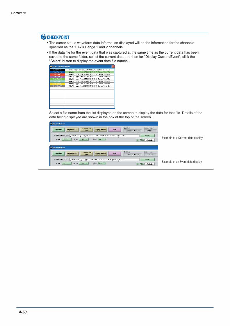
4-50
Software
CHECKPOINT• The cursor status waveform data information displayed will be the information for the channels
specified as the Y Axis Range 1 and 2 channels.
• If the data file for the event data that was captured at the same time as the current data has beensaved to the same folder, select the current data and then for "Display Current/Event", click the"Select" button to display the event data file names.
Select a file name from the list displayed on the screen to display the data for that file. Details of thedata being displayed are shown in the box at the top of the screen.
Example of a Current data display
Example of an Event data display

Software
4-51
Superimpose
A different waveform can be superimposed on the waveform that was displayed when the "OpenFile" button was clicked.
Click the "Superimpose" button to display the "Select File to Superimpose" screen.
Add: Adds the file that you want to superimpose.
Delete: Deletes the file that was superimposed.
OK: Displays the selected data.
Cancel: Cancels the selection.

4-52
Software
Convert then Save
The procedure for converting the displayed data is the same as for "Review Device". Please refer toSection 4.11, "Review Device".
Display in Excel
The procedure for displaying the data in Excel format is the same as for "Review Device". Pleaserefer to Section 4.11, "Review Device".
Click "Print" to output the displayed screen to the printer.

Software
4-53
4.13 Logic, Alarm Display
When the GL500 is in online status, the logic (4 channels) and alarm (4 channels) status can be monitoredon-screen. Logic data can also be monitored as waveforms. Moreover, if a GL400 or GL350 device is alsoconnected, the display can be switched through three modes.
Example of a GL500 Alarm Display
Example of a GL500 + GL400/340 Alarm Display
Example of a GL400/350 Alarm Display

This chapter describes the basic specifications forthe GL500.
CHAPTER 5Specifications
5.1 Standard Specifications5.2 Function Specifications5.3 Accessory/Option Specifications5.4 External Dimensions

5-2
Specifications
5.1 Standard Specifications
Standard Specifications
Item DescriptionNumber of analog input 2 unitsterminal units mountableExternal input/output Trigger input, Logic input or Pulse input, Alarm outputPC interface Ethernet (10 Base-T/100 Base-TX); USB (Ver. 2.0) standardInternal memory devices Current memory : 4 MB (total);
Event memory : 32 MBPCMCIA card slot (Type 2) standard
Data backup functions Setup conditions: EEPROM; Clock: lithium secondary batteryOperating environment 0 to 40°C, 30 to 80% RH (15 to 30°C when the battery is used)Withstand voltage 1 minute at 500 Vp-p (between each input channel and main unit chassis)Power supply AC adapter: 100 to 240 VAC, 50/60 Hz
DC input: 8.5 to 24 VDCBattery pack (option): 7.2 VDC (2200 mAh)
Power consumption+24 V drive 4VF/4MF-AMP x 1
LCD ON: 0.46A, LCD OFF: 0.4A, During battery charging: add 0.42A tothe values at the left
4VF/4MF-AMP x 2LCD ON: 0.61A, LCD OFF: 0.55A, During battery charging: add 0.42A tothe values at the left
8VS-AMP x 1LCD ON: 0.35A, LCD OFF: 0.27A, During battery charging: add 0.42A tothe values at the left
8VS-AMP x 2LCD ON: 0.37A, LCD OFF: 0.3A, During battery charging: add 0.42A tothe values at the left
+12 V drive 4VF/4MF-AMP x 1LCD ON: 0.9A, LCD OFF: 0.75A, Battery cannot be charged
4VF/4MF-AMP x 2LCD ON: 1.2A, LCD OFF: 1.05A, Battery cannot be charged
8MS-AMP x 1LCD ON: 0.7A, LCD OFF: 0.55A, Battery cannot be charged
8MS-AMP x 2LCD ON: 0.8A, LCD OFF: 0.65A, Battery cannot be charged
+8.5 V drive 4VF/4MF-AMP x 1LCD ON: 1.35A, LCD OFF: 1.1A, Battery cannot be charged
4VF/4MF-AMP x 2LCD ON: 1.85A, LCD OFF: 1.55A, Battery cannot be charged
8MS-AMP x 1LCD ON: 1A, LCD OFF: 0.75A, Battery cannot be charged
8MS-AMP x 2LCD ON: 1.15A, LCD OFF: 0.85A, Battery cannot be charged
External dimensions 212 x 162 x 45 mmWeight*1 800 gOther Beeper (key, etc.)
Holes to enable mounting on DIN rails
*1 Excluding the AC adapter and battery; including one amplifier unit.

Specifications
5-3
Internal Memory Devices
PC Interface
Monitor
Item DescriptionMemory capacity Internal memory: 4 MB (current data), 32 MB (event data)
PC card slot: Depends on the type of card usedPC card standard Type 2Usable card types Compact Flash (adapter required)
Memory Stick (adapter required)MicroDrive (1 GB)
Memory contents Setup conditionsMeasured dataScreen copy
Item DescriptionInterface types Ethernet (10 Base-T, 100 Base-TX)
USB (Ver. 2.0)Functions Data transfer to the PC (realtime, memory)
PC control of the GL500Realtime data transfer speed 1 ms maximum*1
*1 Depends on the interface and the number of channels used.
Item DescriptionDisplay 4.7-inch STN color LCD (320 x 240 dots)Displayed languages English, French, JapaneseBacklight life Approx. 36,000 hours (at 23°C, as a reference)Backlight Screen saver function provided (1, 2, 5, 10, 30, 60 min.)Contrast adjustment Provided

5-4
Specifications
Input Unit Specifications (4VF)
Item DescriptionNumber of input channels 4Input terminal type BNCInput method Scanning
All channels isolated, unbalanced inputMeasurement ranges Voltage 100 mV, 500 mV; 1, 5, 10, 50, 100 V
Temperature N/AInput filter Type Line, 5 Hz, 50 Hz, 500 Hz (Line = 1.5 Hz)
Attenuation (–3 dB) at –6 dB/oct.Frequency response DC to 20 kHz (+1/–3 dB typ)Measurement accuracy Voltage ±0.3% of F.S.(23°C±3°C) Temperature N/Awhen 30 minutes have elapsed after thepower was switched on;Line filter On;When the capture mode is CurrentA/D converter 14-bitTemperature coefficient Zero point 0.02% of F.S./°C
Gain 0.02% of F.S./°CInsulation resistance At least 50 MΩ (at 500 VDC)Withstand voltage Between input terminals and GND: 1 minute at 500 VACInput resistance 1 MΩAllowable signal source resistance Within 500 ΩMaximum permissible input voltage
Between +/– terminals 100 mV to 10 V range: 30 V50 V to 100 V range: 100 V
Between insulated parts 33 VAC rms (60 VDC)Common mode rejection ratio 80 dB typ.Noise –46 dB typ. (with +/– terminals shorted)
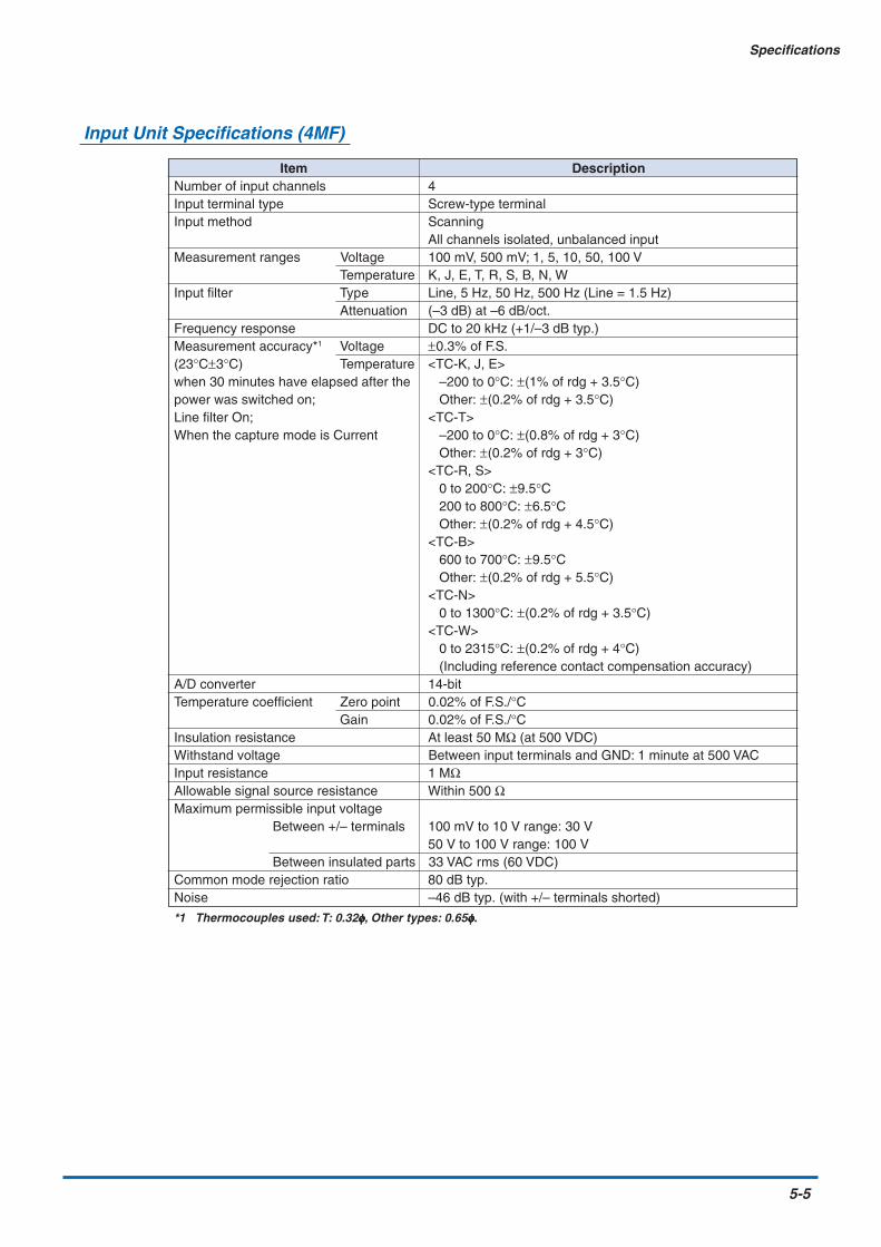
Specifications
5-5
Input Unit Specifications (4MF)
Item DescriptionNumber of input channels 4Input terminal type Screw-type terminalInput method Scanning
All channels isolated, unbalanced inputMeasurement ranges Voltage 100 mV, 500 mV; 1, 5, 10, 50, 100 V
Temperature K, J, E, T, R, S, B, N, WInput filter Type Line, 5 Hz, 50 Hz, 500 Hz (Line = 1.5 Hz)
Attenuation (–3 dB) at –6 dB/oct.Frequency response DC to 20 kHz (+1/–3 dB typ.)Measurement accuracy*1 Voltage ±0.3% of F.S.(23°C±3°C) Temperature <TC-K, J, E>when 30 minutes have elapsed after the –200 to 0°C: ±(1% of rdg + 3.5°C)power was switched on; Other: ±(0.2% of rdg + 3.5°C)Line filter On; <TC-T>When the capture mode is Current –200 to 0°C: ±(0.8% of rdg + 3°C)
Other: ±(0.2% of rdg + 3°C)<TC-R, S> 0 to 200°C: ±9.5°C 200 to 800°C: ±6.5°C Other: ±(0.2% of rdg + 4.5°C)<TC-B> 600 to 700°C: ±9.5°C Other: ±(0.2% of rdg + 5.5°C)<TC-N> 0 to 1300°C: ±(0.2% of rdg + 3.5°C)<TC-W> 0 to 2315°C: ±(0.2% of rdg + 4°C) (Including reference contact compensation accuracy)
A/D converter 14-bitTemperature coefficient Zero point 0.02% of F.S./°C
Gain 0.02% of F.S./°CInsulation resistance At least 50 MΩ (at 500 VDC)Withstand voltage Between input terminals and GND: 1 minute at 500 VACInput resistance 1 MΩAllowable signal source resistance Within 500 ΩMaximum permissible input voltage
Between +/– terminals 100 mV to 10 V range: 30 V50 V to 100 V range: 100 V
Between insulated parts 33 VAC rms (60 VDC)Common mode rejection ratio 80 dB typ.Noise –46 dB typ. (with +/– terminals shorted)
*1 Thermocouples used: T: 0.32φφφφφ, Other types: 0.65φφφφφ.

5-6
Specifications
Input Unit Specifications (8MS)
Item DescriptionNumber of input channels 8Input terminal type Screw-type terminalInput method Scanning
All channels non-isolated, balanced inputMeasurement ranges Voltage 100 mV, 500 mV; 1, 5, 10 V
Temperature K, J, E, T, R, S, B, N, WInput filter Type Line, 5 Hz, 50 Hz, 500 Hz (Line = 1.5 Hz)
Attenuation (–3 dB) at –6 dB/oct.Frequency response DC to 20 kHz (+1/– 4.5 dB typ.)Measurement accuracy*1 Voltage ±0.3% of F.S.(23°C±3°C) Temperature <TC-K, J, E>when 30 minutes have elapsed after the –200 to 0°C: ±(1% of rdg + 3.5°C)power was switched on; Other: ±(0.2% of rdg + 3.5°C)Line filter On; <TC-T>When the capture mode is Current –200 to 0°C: ±(0.8% of rdg + 3°C)
Other: ±(0.2% of rdg + 3°C)<TC-R, S> 0 to 200°C: ±9.5°C 200 to 800°C: ±6.5°C Other: ±(0.2% of rdg + 4.5°C)<TC-B> 600 to 700°C: ±9.5°C Other: ±(0.2% of rdg + 5.5°C)<TC-N> 0 to 1300°C: ±(0.2% of rdg + 3.5°C)<TC-W> 0 to 2315°C: ±(0.2% of rdg + 4°C) (Including reference contact compensation accuracy)
A/D converter 14-bitTemperature coefficient Zero point 0.02% of F.S./°C
Gain 0.02% of F.S./°CInsulation resistance Non-isolatedWithstand voltage Non-isolatedInput resistance 1 MΩAllowable signal source resistance Within 500 ΩMaximum permissible input voltage
Between +/– terminals 100 mV to 10 V range: 10 VBetween insulated parts Non-isolated
Common mode rejection ratio Non-isolatedNoise –46 dB typ. (with +/– terminals shorted)
*1 Thermocouples used: T: 0.32φφφφφ, Other types: 0.65φφφφφ.

Specifications
5-7
5.2 Function Specifications
Function Types
Trigger Functions (Current)
Trigger Functions (Event)
Item DescriptionTrigger repeat Off, OnTrigger types Start: Data capture starts when a trigger is activated.
Stop: Data capture stops when a trigger is activated.Trigger settings Start: Off, Level, Date, External
Stop: Off, Level, Date, External, Time, Event fullAlarm judgment modes Analog, Logic or Pulse AND or OR
• Analog: H, L, Window In, Window Out • Logic: 4-ch pattern • Pulse: H, L, Win In, Win Out
Item DescriptionDisplay screen Waveform display + digital display, Full-screen waveform display,
Digital displayNote: Can be key-toggled
Sampling interval Current data: 1, 2, 5, 10, 20, 50, 100, 200, 500 msec1, 2, 5, 10, 20, 30 sec 1, 2, 5, 10, 20, 30 min 1 hour
Event data: (2, 4, 5, 8, 10) 20, 40, 50, 100, 200, 500 µsec1, 2, 5, 10, 20, 50, 100, 200, 500 msec 1 secNote: Selection of the values within parentheses ( ) depends on the type
of amplifier installed and the number of channels used.
EU (Scaling function) 4 points can be set for each channelReview function Data replay during data captureData save functions Capture to internal memory
Capture to internal memory and automatic save to a PC cardDirect capture to a PC card (current data only)Setup conditions saved to a PC cardCopy of data screen saved to a PC card
Statistical calculation Types of operation: Average value, peak value, maximum value, minimumvalue, RMS
Number of operations: A maximum of 4 can be set simultaneouslyArithmetic operations: +, –, x, / (calculation can be performed for 2
channels of data only)Method: Realtime operation*1
Note: The calculation results are displayed in the digital display mode
Search functions Function: Searches the captured data for the required number of pointsSearch types: Level, alarm, event
Annotation input function Function: A comment can be input for each channelInputtable characters: AlphanumericsNumber of characters: 11
*1 Arithmetic operations can only be performed in real time. Statistical calculations are captured in real time.
Item DescriptionTrigger types Start: Off, Level, External
Pre-trigger: 0, 10, 20, 30, 40, 50, 60, 70, 80, 90, 100 %Stop: Off, Level, External
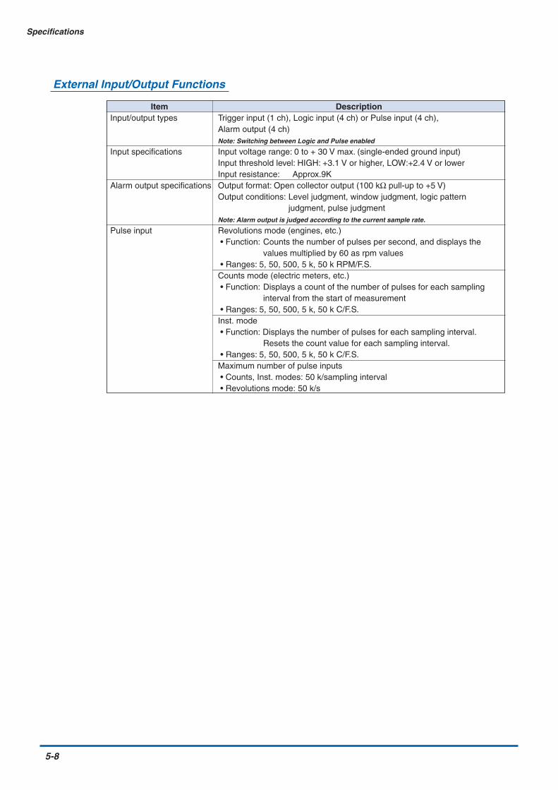
5-8
Specifications
External Input/Output Functions
Item DescriptionInput/output types Trigger input (1 ch), Logic input (4 ch) or Pulse input (4 ch),
Alarm output (4 ch)Note: Switching between Logic and Pulse enabled
Input specifications Input voltage range: 0 to + 30 V max. (single-ended ground input)Input threshold level: HIGH: +3.1 V or higher, LOW:+2.4 V or lowerInput resistance: Approx.9K
Alarm output specifications Output format: Open collector output (100 kΩ pull-up to +5 V)Output conditions: Level judgment, window judgment, logic pattern
judgment, pulse judgmentNote: Alarm output is judged according to the current sample rate.
Pulse input Revolutions mode (engines, etc.) • Function: Counts the number of pulses per second, and displays the
values multiplied by 60 as rpm values • Ranges: 5, 50, 500, 5 k, 50 k RPM/F.S.Counts mode (electric meters, etc.) • Function: Displays a count of the number of pulses for each sampling
interval from the start of measurement • Ranges: 5, 50, 500, 5 k, 50 k C/F.S.Inst. mode • Function: Displays the number of pulses for each sampling interval.
Resets the count value for each sampling interval. • Ranges: 5, 50, 500, 5 k, 50 k C/F.S.Maximum number of pulse inputs • Counts, Inst. modes: 50 k/sampling interval • Revolutions mode: 50 k/s

Specifications
5-9
5.3 Accessory/Option Specifications
Control Software
Battery Pack (Option)
Item DescriptionCompatible operating Windows 2000/XPsystemFunctions Main unit control, realtime data capture, data conversionMain unit settings Input settings, memory settings, alarm settings, trigger settingsCaptured data Realtime data (CSV, Binary)
Memory data (CSV, Binary)PC card data
Displayed items Analog waveforms, logic waveforms, pulse waveforms, digital valuesDisplay modes Waveform display, digital displayFile conversion Between cursors, all dataMonitor functions Alarm monitor enables the sending of email to the specified addressDual-screen function Displays the current data together with past dataMax./Min. Displays the maximum, minimum, and current values during measurementFFT functions
Item 4VF 4MF 8MSCapacity 7.2V/2200 mAhBattery type Lithium secondary batteryRunning time When the LCD is ON When the LCD is ON When the LCD is ONat +25°C • x1: Approx. 40 minutes • x1: Approx. 40 minutes • x1: Approx. 1 hour and(The running time 30 minutesvaries according to • x2: Approx. 20 minutes • x2: Approx. 20 minutes • x1: Approx. 1 hourthe environment) When the LCD is OFF When the LCD is OFF When the LCD is OFF
• x1: Approx. 1 hour and • x1: Approx. 1 hour and • x1: Approx. 2 hours30 minutes 30 minutes
• x2: Approx. 40 minutes • x2: Approx. 40 minutes • x1: Approx. 1 hour and30 minutes
Charging method Mount in the main unitWhile the GL500 is in use, factors such as the condition of the installed amplifiers,the operating temperature, and the length of continuous use may prevent chargingof the battery. (Charging is controlled by monitoring the temperature)
Time required for Approx. 4 hours when the power supply is OFFchargingSwitchover in the Because the battery is used together with the AC adapter, the power supply will becase of a power switched automatically to the battery drive in the event of a power failure.failure Note: The AC adapter is the primary power source.
Operating 15 to 30°CenvironmentOther functions When the battery is running low, memory data is saved automatically to the PC
card.When data is being saved directly to the PC card, the file is closed automatically.

5-10
Specifications
5.4 External Dimensions
GL500
1015
245
212

Index
I-1
Index
Symbols4MF Input Terminal Unit ...................................2-164VF Input Terminal Unit ....................................2-158MS Input Terminal Unit ...................................2-17
AAC
Drive ..............................................................2-4Power Supply ................................................2-9
Accessories ........................................................2-2Alarm
Display ........................................................4-53Display area ..................................................2-4Output functions ..........................................2-19Output terminal .............................................2-3Settings .............................................3-17, 4-24
AMP .................................................................4-20Settings .......................................................4-14
Amp Settings ......................................................3-8Edge ..................................................3-19, 3-20Level Trigger ................................................3-17
Amp Trigger Settings ........................................4-23Analog
AMP Settings ..............................................4-20Signal monitor area .......................................2-4
Annotation Strings ............................................3-11Application Software
Exiting .........................................................4-19Launching ...................................................4-13Measurement Example ...............................4-13Starting the ....................................................4-9
Arithmetic .........................................................3-21Operation ....................................................4-31
Arithmetic, XY, FFT ..........................................4-31Auto
Backup Settings ..........................................4-28Save to PC after Capture ............................4-25
Available SPAN Settings ....................................3-9
BBattery ................................................................2-3
Charging .....................................................2-12Charging LED ...............................................2-3Drive ..............................................................2-4Pack ............................................................2-11Pack Specifications .......................................5-9
CCALC Settings..................................................3-21Calculation .......................................................4-42Capture Destination .........................................3-14Card Initialize ...................................................3-23CH GROUP key .........................................2-6, 3-2Combination .....................................................3-17Configuration When in Use ................................1-5Confirm Start/Stop ...........................................3-25Connecting
PC .........................................................2-8, 4-6Power Cable ..................................................2-9Signal Input Cables
to the Input Terminal Unit .......................2-15Control
Panel Key Names and Functions ..................2-6Panel keys ....................................................2-3Software Specifications .................................5-9
Convert then Save .................................4-46, 4-52Copy File ..........................................................4-29CRNT Settings .................................................3-13Current .............................................................4-22
Data (Displaying the) ..................................4-17Data between Cursors Display ...................4-39Data Display ................................................4-39Settings .............................................3-13, 4-15
CURSOR key .............................................2-7, 3-6Cursor Position .................................................3-35
DData........................................................4-46, 4-47
Capture LED .................................................2-3Capture Start/Stop ......................................4-35Replay .........................................................3-28Transfer .......................................................4-28
Date and Time (Setting) ...................................2-21Date/Time.........................................................3-26
Display area ..................................................2-4DC Power Supply .............................................2-10Decimate waveform..........................................3-26Delete
File ..............................................................4-29Folder ..........................................................4-29
DeviceID ..................................................................4-8Settings .......................................................4-22

I-2
Index
Digital View.............................................4-17, 4-40Direction keys.............................................2-6, 3-5DISPLAY key ..............................................2-6, 3-5Display Language (Changing the) ......................1-6
EEcho Back ........................................................3-34ENTER key ........................................................2-6EU (Engineering Unit Settings) ..........................3-9Event ................................................................4-25
Data display ..................................................2-5Data Replay ................................................4-40Max. Speed Sampling .................................4-20Settings .............................................3-18, 4-15Trigger .........................................................3-19Trigger Settings ...........................................4-26
EVNT Settings ..................................................3-18Excel (Display) .......................................4-47, 4-52External
Dimensions .................................................5-10Input/Output Functions ..................................5-8Trigger Functions ........................................2-20Trigger terminal .............................................2-3
FFactory Default Settings ...................................4-33Features .............................................................1-3FFT.........................................................4-31, 4-41File ...................................................................4-28
Copy ............................................................3-22Delete ..........................................................3-22Extensions ..................................................3-23List ..............................................................3-22Name ..........................................................3-14Opening ............................................4-43, 4-49Rename ......................................................3-22Selecting a ..................................................4-18Settings .............................................3-22, 4-16
Filter ...................................................................3-9Firmware Version ...............................................4-8Format ....................................................4-29, 4-46Function .................................................3-18, 3-21
EU .................................................................3-9Types .............................................................5-7
GGL400/350 .......................................................4-36GL500 + GL400/350 ........................................4-38GND terminal .....................................................2-3Grid ..................................................................3-25
II/F Settings .......................................................3-24INFO Display ....................................................3-27Information .......................................................4-34Input ...................................................................3-8
Data (Capturing) .........................................4-16Terminal Unit .......................................2-3, 2-14Unit Specifications (4MF) ..............................5-5Unit Specifications (4VF) ..............................5-4Unit Specifications (8MS) ..............................5-6
Installing the GL500 Application Software .........4-7Internal Memory Devices ...................................5-3IP Address ..........................................................4-8
KKey lock..............................................................2-4
LLAN
Cable .....................................................2-8, 4-6Connector terminal ........................................2-3Settings .........................................................4-8
Language .........................................................3-26Line Color .........................................................3-11Load settings ....................................................3-22Logic.................................................................3-13
Display ........................................................4-53Input functions .............................................2-19Input terminal ................................................2-3Settings .......................................................4-21
Logic, Pulse Settings........................................4-21Logic/Pulse.........................................................3-8
Settings display area .....................................2-4Lower - EU - Upper Unit .....................................3-9
MMac Address ......................................................4-8Measurement Parameter Settings ...................4-20Memory block capture display area ...................2-4Memory/PCMCIA display area ...........................2-5Menu Configuration ............................................4-9MENU key ..........................................2-6, 3-6, 3-7Misc. .................................................................3-10Monitor ...............................................................2-3
Control dial ....................................................2-3Part Names and Functions ...........................2-4Specifications ................................................5-3
NNew Line Code.................................................3-24

Index
I-3
No.of block divisions .........................................3-19of CH .............................................................3-8
Noise Countermeasures ..................................2-18Notes
Temperature Measurement ...........................1-6Using the Monitor ..........................................1-6
Number ............................................................4-20
OOperating Environment ......................................1-5Other ................................................................4-33OTHR Settings .................................................3-25Outer Casing (Checking the) ..............................2-2Overview ............................................................1-2
PPart Names and Functions.................................2-3Path ..................................................................4-46PC
Card Information .........................................3-23Card Settings ..............................................4-22Connection Settings ....................................4-12Data (Replaying) .........................................4-18Data Capture Settings .................................4-28Interface Specifications .................................5-3
PCMCIACard ............................................................2-13Card access display ......................................2-4Slot ................................................................2-3
Pen display.........................................................2-4Perform Auto Zero ADJ ....................................3-12Port Number .......................................................4-8POSITION settings.............................................3-4Power
Connector .....................................................2-3LED ...............................................................2-3On Start ............................................3-26, 4-33Switch ...........................................................2-3
Pre Trigger ........................................................3-19Print ........................................................4-47, 4-52Printing Displayed Data....................................4-19Processing mode display area ...........................2-4Pulse ................................................................3-12
Input functions .............................................2-19Input terminal ................................................2-3Settings .............................................4-21, 4-30
QQUIT key ....................................................2-6, 3-6
RRange.................................................................3-9RANGE settings .................................................3-3RANGE/SPAN/POSITION key ...................2-6, 3-3Readout
Menu ...........................................................3-34Rechargeable Battery (Charging the) ..............2-21Remote...............................................................2-4Repeat..............................................................3-17Replaying
Data ............................................................4-18Reset Auto Zero ADJ .......................................3-12Return to default settings .................................3-26Review
Device .........................................................4-43PC ...............................................................4-48
REVIEW key ..............................................2-7, 3-5Room Temp. Compensation ...................3-26, 4-33
SSampled Waveform Display .............................4-33Sampling Interval ...................................3-13, 3-18Save
Current settings ...........................................3-22to Card (Between Cursors) .........................3-37
SAVE key ...................................................2-7, 3-6Scale
upper/lower limit ............................................2-5View Mode ..................................................3-25
Scaling .............................................................4-30Screen Saver....................................................3-26Screwdriver ........................................................2-3Search ..............................................................3-35Select CH ...............................................4-20, 4-30Send E-mail ......................................................4-33Set Zero Point as..............................................3-12Setting
Parameters .................................................4-14Procedures ....................................................3-7
Simplified message display area ........................2-4Software .............................................................4-1Source ..........................................3-15, 3-19, 3-20SPAN settings ....................................................3-4Spot Samples .........................................4-46, 4-47Standard Specifications .....................................5-2START/STOP key ......................................2-6, 3-4Stat Calc. ..........................................................4-31Statistical ..........................................................3-21
Calculation ..................................................3-36Store the settings to the GL500 .......................4-33

I-4
Index
Sub Net Mask.....................................................4-8Superimpose ..........................................4-45, 4-51Synchronize PC and device clocks ..................4-33System
Requirements ................................................4-2Settings .........................................................4-9
TTCP-IP Settings ...............................................3-24Temp. Unit ..............................................3-26, 4-33Temperature Ranges ..........................................3-9TIME/DIV
Display area ..................................................2-4key.........................................................2-6, 3-4
TriggerFunctions ......................................................5-7Settings .............................................3-15, 4-22
Turning on the Power .........................................2-9
UUSB
Cable .....................................................2-8, 4-6Connector terminal ........................................2-3Driver (Checking the version) .......................4-3Driver (Installing the) .....................................4-4ID Setting ....................................................3-24Setting ...........................................................4-8
VView Functions .................................................4-35Voltage Ranges ..................................................3-9
WWarming-up ........................................................1-5Waveform/settings window display area ............2-5
XX-Y ...................................................................4-41XY ....................................................................4-31
YY-T ....................................................................4-39

The specifications, etc., in this manual aresubject to change without notice.
GL500-UM-152July 30, 2005 1st edition-01
GRAPHTEC CORPORATION

503-10 Shinano-cho, Totsuka-ku,Yokohama 244-8503, JapanTel : +81 (045) 825-6250Fax : +81 (045) 825-6396Email : [email protected] : www.graphteccorp.com
Printed in Japan