Embed Size (px)
Citation preview
1
GJD mini Opal 30 metre External PIR
Installation and Set Up Guide
The mini Opal is an attractively styled, 30 metre Passive Infrared (PIR) detector that works with GJD security lighting controllers. The mini Opal has additional advanced PIR features as follows:
Sensor mounted white-light filter (sun glasses) to prevent false detections on sunny days
Dual tamper switches for case and wall-mount tamper detection
Zone blanking using vertical curtains and horizontal foil for precise area coverage
±90° horizontal and ±45° vertical aim adjustment
Conformally coated electronics for enhanced UV and moisture resilience
Attractive, 21st century styling with a protective cover to disguise sensor direction
Field of View
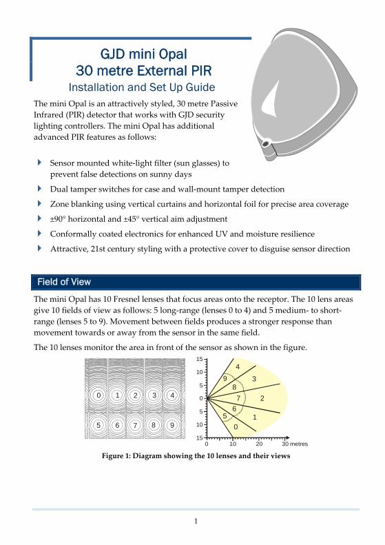
The mini Opal has 10 Fresnel lenses that focus areas onto the receptor. The 10 lens areas give 10 fields of view as follows: 5 long-range (lenses 0 to 4) and 5 medium- to short-range (lenses 5 to 9). Movement between fields produces a stronger response than movement towards or away from the sensor in the same field.
The 10 lenses monitor the area in front of the sensor as shown in the figure.
10 20 30 metres0
15
5
10
15
0
5
105
01
67 2
839
4
0
5
1
6
2
7
3
8
4
9
Figure 1: Diagram showing the 10 lenses and their views


4
WARNING: Always make the appropriate checks to ensure that the surface you are drilling does not contain mains electrical wiring or plumbing. Failure to do so can result in injury or death by electric shock.
6) Feed the cable(s) through the grommet(s) and fix the unit in your chosen location using appropriate fixings (not supplied).
Connect
Caution: To prevent damage to your mini Opal or lighting controller, switch off the power before making connections.
1) Connect the +, A, S and - wires to the screw-terminal block on the back of the sensor PCB.
A S +
Figure 6: Rear of PCB with Output Connections
1) Optionally connect the tamper output on the top PCB to your alarm system.
Note: The twin tamper switches provide a single volts-free, normally-closed alarm output once the mini Opal is mounted to the wall and the cover is fitted.
Figure 7: mini Opal Tamper Board
1) If required, see Connect External Buzzer or Relay (on page 5).
When the power is applied, the red LED flashes for 0.5 seconds before stopping. The LED is normally off during operation.

5
Connect External Buzzer or Relay
The unit can drive an external relay output or a piezo buzzer. The component specifications for the diagrams are:
Diodes: 1N4148/1N4002 or similar - observe the band when connecting
External relay: 12V DC, 470 ohm minimum coil resistance
Piezo buzzer: 12V DC, 3mA, 80dB(A) at one metre
Energizing a relay from the A or S connections
When the external relay is connected to the A connection, it will trigger for every detection and deactivate immediately. By connecting the relay to the S connection, the external relay stays active from 60s following the last detection.
+ +S
S
AA
mini Opal
-
-
+
-
12V DC
GJD LightingController
Figure 8: External relay wiring diagram
Driving a Piezo Buzzer from the A connection
This configuration can be useful as a temporary measure during your walk-test. The piezo buzzer will sound every time a detection takes place.
+ +S
S
AA
mini Opal
-
-
+
-
12V DC
GJD LightingController
~
Figure 9: Piezo buzzer wiring diagram

7
Specifications
Coverage (max) 90° at 30m, equivalent to 625m2
Reach Adjustable 9m to 30m
Directional adjustment ±90° horizontal (180°), ±45° vertical (90°)
Area adjustment (blanking) Supplied with, 1 foil label for near/far beam blanking and 4 vertical opaque curtains for zone blanking
Lens 2 rows of 10 beams
Sensor White light filter prevents false triggering when sunny
Output A (Alarm) Open-collector transistor switch. 12V, 25mA alarm current
Output S (Sensor, daylight) Open-collector transistor switch. 12V, 25mA alarm current
Output T (Tamper) Volts-free, normally-open switch output
Tamper switches Case open and removal from wall
Power 9 to 15V DC
Current 4mA at 12V
Operating Temperature -20°C to +55°C
Protection IP55, high-impact ABS housing. Conformal coated electronics (moisture and UV protection lacquer)
Dimensions 84 x 106 x 72 mm
Mounting Suggested height 3m
Cabling 0 to 200m: standard, 4-core, 7/0.2mm alarm cable
200 to 500m: 8-core, 16/0.2mm (use double cores)
Approvals
The manufacturer declares that the product supplied is compliant with the provisions of the EMC Directive 89/336/EEC amended 92/31/EEC for Electromagnetic Compatibility, and the Restriction of Hazardous Substances Directive (RoHS) 2002/95/EC. A Declaration of Conformity in accordance with the above directives is held on file with the manufacturer.