Embed Size (px)
Citation preview

Industrial Automation Infrastructure Solutions
Paul Herbst, ICN Solutions Sales Manager Mike Berg, Solutions Marketing Manager
Give Your Process Plant aBackboneA Standards-Based Approach to the Industrial Physical NetworkCT521, Process Solutions Summit, March 2015

Cabling Infrastructure
Agenda
2
Physical Network Design ProcessPhysical Network Design Process
Turning Vision Into Reality
Business & Solution Trend

Challenges to Transforming Industry
Organizations are challenged to leverage technology and networks to connect the factory and enterprise boosting productivity, innovation, business agility.
“The productivity economy will reward ‘do it smarter’ companies that build a better business model.”McKinsey Global Forces: The productivity imperative, McKinsey & Company
“The productivity economy will reward ‘do it smarter’ companies that build a better business model.”McKinsey Global Forces: The productivity imperative, McKinsey & Company

Internet of Things Impact
• 100% of plant floor devices will be providing data by 2018.
• Every day 160,000 NEW industrial Ethernet nodes are connected.I.H.S. Global/IMS Research
• The Internet of Things (IoT) is expected to enable manufacturers to generate $3.88 trillion in global profits over the next 10 years.
Not all manufacturers are ready or fully understand how to capitalize on this opportunity!
Not all manufacturers are ready or fully understand how to capitalize on this opportunity!
In 2009 2.5 billion devices were connected with unique IP addresses.By 2020, up to 30 billion devices –and mostly are “things.” Gartner
www.industrial‐ip.org

• 8 hours downtime (99.91% uptime)
• 11% reduced Total Cost of Ownership (TCO) for industrial network
• 90% Overall Equipment Effectiveness (OEE)
• +25% operating margin contribution
Profiling the Best‐in‐Class Manufacturers
Source: Aberdeen Group, Industrial Networking Real‐time Foundation for Manufacturing and Enterprise, August 2012
71% 65%56%
48%40% 34%
52%
35%
0%
10%
20%
30%
40%
50%
60%
70%
80%
Reliability built into thephysical layer of the
network
Data‐link reliability Network management(apps and devices used tomonitor performance andcontrol network access)
Cablingmanagement/wiringstrategy that is aligned
with industrialnetworking architecture
Network Management
Best In Class All Others
Discipline in the network provides resultsDiscipline in the network provides results

Infrastructure Investment Compared to Longevity
• 60%• 2 to 5 years
Software
• 23%• 5 Years
Networking
• 10%• 5 Years
Operations
• 7%• 20+ years (or forever!)
Cabling
80% of network problems are caused by only 7% of invested budget.
80% of network problems are caused by only 7% of invested budget.

Preventable Network Distribution Installation Issues
Poor infrastructure planning puts both performance and security at risk!
“A significant portion of network downtime, approx. 80%, is attributed to Physical Layer Connections.” Sage Research
“A significant portion of network downtime, approx. 80%, is attributed to Physical Layer Connections.” Sage Research
“40% list Security concerns as a barrier to enabling Internet connectivity to machines” Industry Week Magazine Rockwell Automation Survey
“40% list Security concerns as a barrier to enabling Internet connectivity to machines” Industry Week Magazine Rockwell Automation Survey

Invest Now or Pay Much More Later!
$10 $100$1000
$10,000
Plan Design Build Deploy/Operate
$$
Relative Cost to Resolve Problems
Source: www.motioncontrolonline.Mechatronics Part I: Motion Control’s Next Top Model; Aberdeen Group, The Mechatronic System Design Benchmark Report.
Cost to resolve issues increases exponentially throughout the design cycle Reality:
>35% resolved late
Reality:>35% resolved late

Turning Vision into a Reality …
Building a standards based roadmap to
reduce risk and ease company‐wide adoption
9
Navigating Network
Architectures
Knowing Where to Start with Physical Design
• Ensure performance, uptime and productivity
• Build reliability, reduce troubleshooting time
• Ease integration with a standards based approach that is modular and scalable
• Reduce cost and time to production
• Ensure performance, uptime and productivity
• Build reliability, reduce troubleshooting time
• Ease integration with a standards based approach that is modular and scalable
• Reduce cost and time to production
… that Achieves Benefits:

Developed by the TIA TR‐42.9 Industrial Infrastructure Subcommittee and published in May 2012, the Standard provides infrastructure, distance, telecommunications outlet/connector configuration, and topology requirements for cabling deployed in industrial environments.
• Industrial Areas
• Telecommunications Spaces
• Telecommunications Pathways
• Firestopping
• Backbone Cabling
• Horizontal Cabling
• Work Area
• Grounding and Bonding
• Industrial Cabling Performance Requirements
Industrial PremisesTelecommunications Standards

Applicable Industrial StandardsTelecommunications Standards
• ANSI/TIA‐1005 is explicitly supported by the 568‐C cabling standard
• TIA/EIA‐568‐C Defines cabling types, distances, connectors, cable system architectures, cable termination standards and performance characteristics, cable installation requirements and methods of testing installed cable
• C.0 defines the overall premises infrastructure for copper and fiber cabling
• C.2 addresses components of the copper cabling system
• C.3 addresses components of fiber optic cable systems
ANSI/TIA-568-C.0(Generic)
TIA-569-B(Pathways and
spaces)
ANSI/TIA-606-A(Administrative)
ANSI/TIA-607-B(Bonding and
grounding / earthing)
ANSI/TIA-758-A(Outside plant)
ANSI/TIA-862
(Building automation systems)
ANSI/TIA-568-C.1(Commercial)
ANSI/TIA-570-B(Residential)
ANSI/TIA-942(Data centers)
ANSI/TIA-1005(Industrial)
ANSI/TIA-1179(Healthcare)
ANSI/TIA-568-C.2(Balanced
twisted-pair)
ANSI/TIA-568-C.3(Optical fiber)
ANSI/TIA-568-C.4(Coaxial)
Common Standards Premises Standards Component Standards

Structured Cabling: A planned cabling system which systematically lays out the wiring and wire management necessary for communications, including voice, data and video.
Industrial Physical Layer Road Map
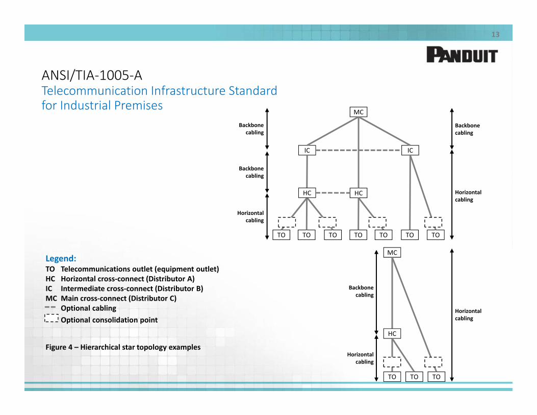
ANSI/TIA‐1005‐ATelecommunication Infrastructure Standard for Industrial Premises
13
MC
IC IC
HC
TO TO TO TO TO TO TO
MC
TO TO TO
HC
HC
Backbone cabling
Backbone cabling
Horizontal cabling
Horizontal cabling
Backbone cabling
Backbone cabling
Horizontal cabling
Horizontal cabling
Legend:TO Telecommunications outlet (equipment outlet)HC Horizontal cross‐connect (Distributor A)IC Intermediate cross‐connect (Distributor B)MC Main cross‐connect (Distributor C)
Optional cablingOptional consolidation point
Figure 4 – Hierarchical star topology examples
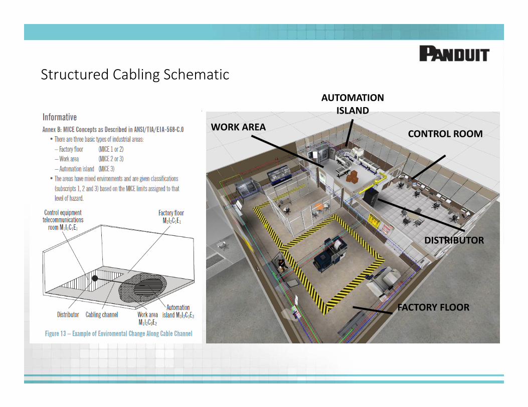
Structured Cabling SchematicAUTOMATION
ISLAND
CONTROL ROOMWORK AREA
FACTORY FLOOR
DISTRIBUTOR

M.I.C.E diagramming allows the design to balance component costs with mitigation costs in order to build a robust yet cost‐effective system.
Structured Cabling Schematic
M1I1C2E2
M1I1C1E1
AUTOMATION ISLAND
CONTROL ROOMWORK AREA
FACTORY FLOOR
DISTRIBUTOR
M1I2C3E2
M3I3C3E3

AssessmentNetwork Availability Considerations
• The degree of Availability is drivenby the downtime cost
– Balance network resiliency costs and downtime costs
• Different types of resilient network topologies impact the physical layer
– Path and device separation
• Different grades of hardening to choose from– Cable jacket/outer– Device protection/cooling
• Connection reliability– Tested, i.e. not just green light on– Installation best practices

Customer Case Example: Application Needs & Challenges
Budget ConstraintsBudget Constraints
Project: Redesign and build a new Process Control Network Infrastructure for a
multi‐building Industrial manufacturing campus environment.
Project: Redesign and build a new Process Control Network Infrastructure for a
multi‐building Industrial manufacturing campus environment.
Internal Resource Limitations
Internal Resource Limitations
Provide secure network environment
Provide secure network environment
Overcome Ad‐hoc DIY in‐house approachesOvercome Ad‐hoc DIY in‐house approaches
DocumentationDocumentation
High availability network system
High availability network system
Scalable for future changes and upgrades
Scalable for future changes and upgrades

Network Upgrade Project: Key Needs
• Choosing framework of the logical architecture
– Lessons learned from “pilot” plants– Whether to accept or reject tribal IT knowledge
• Specification and installation of new fiber backbone
– Selecting media type for backbone – Environmental considerations
• Creating a plan for switch deployment– Control room deployments– Plant floor deployments– Expertise for where and how to deploy
• Creating a phased project deployment plan– Enabling legacy network during transition

Physical Network Design ProcessDefine the Logical Architecture:
• How many nodes are on the network? What types of nodes?
• How critical are these nodes to process and to safety?
• What type of traffic?
• What are the performance requirements? How much data? How fast?
• Availability?
• Who owns what in the infrastructure?
• System Environment? Noise concerns? Distance concerns?
• Data Flow?
• What are the security policies?
• Are there remote user requirements?
• Integration into existing systems?

Physical Network Design ProcessFocus
Translating logical network architecture requirements into physical infrastructure designs.Designing based on MICE boundary analysis.Optimizing the physical infrastructure to enhance Layer 2/3 network performance.
11
22
33

Sample Industrial Network Layer 1 Physical Infrastructure Topology

Process Training Unit: PlantPAx
PlantPAx Virtualized environment ‐
• Speed Deployment and High Availability
• Robust Physical Infrastructure:• Cable Management• Grounding/Bonding• Fiber, Copper Connectivity• Physical Security• Identification• Power Outlet Units
Essentials + from Rockwell Automation

Dielectric Conduit‐tedFiber Distribution Cable
DIN mount enclosure to break out and protect buffered fibers
Fiber Panel to create testable permanent links on distribution cable
LC to LC Jumpers to Ethernet Switch uplink
Copper patch panel and horizontal cable distribution
Integrated Network Zone SystemIndustrial ArchitectureExample of Fiber to the Telecom Enclosure (FTTE)

Intermediate Distribution Frame (IDF)
• Rapidly deploy 19” rack mount switches in a zone architecture within plant environment
– Accommodates two distribution layer switches (Cisco 3750X)
– Three access layer switches (Cisco 2960S) with UPS– Double hinge feature allows front and rear access to
network switch equipment– Cable management features to secure horizontal fiber and
copper in a reliable, consistent manner– UL Type 4/12 and IP66 enclosure– Thermally tested and validated for a highly reliable system
• Scalability– Single part number simplifies the design and execution for
a fast and repeatable solution
• Security– Protect the integrity of cabling media and also enable
physical layer access control over critical network systems
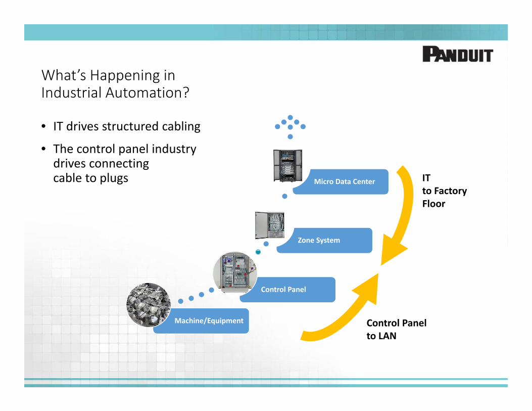
What’s Happening in Industrial Automation?
• IT drives structured cabling
• The control panel industry drives connecting cable to plugs
Machine/Equipment
Control Panel
Zone System
Micro Data Center IT to Factory Floor
Control Panel to LAN

Structured Cabling – Solid horizontal cable terminated with
jacks– Typically installed and left in place;
measured and warranteedperformance
– Connected to equipment with flexible patch cords
Point to Point Cabling– Stranded cable field terminated
with plugs;– Measurements infrequently done – No standard exists to define the
measurement method– If the green light goes on,
then it works
Structured and Point to Point Cabling

• Consists of patch cords, jack (patch panel), and horizontal cabling
• Accurately test horizontal cable
• Panduit patch cords 100% tested
• Easier to reliably terminate to a jack compared to a plug
• Can have spare or redundant links– Aids in troubleshoot– Easier to add connections “on the
fly”– Can plan for the future
27
Structured Cabling

• Single cable terminated to plugs
• Most often stranded conductors for flexibility
– Solid cable prone to break– De‐rated length
• Testing can be inaccurate
• Plugs can be hard to terminate reliably for the long term especially for higher bandwidth cable
• Can not plan for the future– Extra cables are not secure
28
Point to Point Cabling

Where Would You Consider Using Structured or Point to Point Cabling?
Primary Considerations Structured Cabling Point to Point Cabling
Meet Design Specifications
• High cable quantity – many cables from panel to machine
• Customer verification and testing required from installer
• Warranty
• Low cable quantity – few cables from panel to machine
• Ring or linear topology for reach beyond 100M where distance between connection is < 100M
Network Longevity (Future Proof)
• Designed in spare ports • Difficult to have spare connectivity
Maintainability (Moves, Adds, Changes)
• Environments with multiple changes occurring
• Cable slack is required
• Environments with minimal changes occurring
• Slack cabling is undesired and precise cable lengths are required
Installation
• Multiple points of connectivity• Horizontal cabling is largely untouched
• Quick and easy installation• Where tight bends or moderate flexing
is required• Areas where it is impractical or
impossible to mount a patch panel or other horizontal cable jack interface

Cabling Infrastructure – A Facility Assessment
Consideration Assessment Design Impacts
Connectivity Count Number of Devices, Machines, etc.
Cable Runs, Pathway Capacity, Port Count, etc.
Environment Mechanical, Ingress, Climatic/ Chemical, Electro Magnetic
Protection, Separation, Transmission Media (Cu vs. Fiber)
Bandwidth Current Network Utilization & FutureLoad
Cable Media, Switches, Installation
Cable Reach Cable Length Cable Media, Switches
Safety Nearby High Voltage Device Access, Protection
Security Threat Level, Isolation Port Protection, Access,
Longevity Years of Service Bandwidth, Hardening, Manufacturing Growth

Media Selection
Parameter Copper Cable Multi-mode Fiber Single-mode Fiber
Reach (max) 100m (330ft) 500m (1,750ft) 40km (24 miles)
Noise Mitigation Foil shielding Noise immune Noise immune
Bandwidth 1 Gb/s 10 Gb/s 10 Gb/s
Cable Bundles Large Medium Small
Power Over Ethernet (PoE) Capable Yes No No

• TIA‐1005 supplements TIA‐568 providing guidance on industrial specific issues: EMI and environmental factors, channel connection options, 2 / 4 pair cabling, and derating factors.
• ODVA provides EtherNet/IP media planning and installation standards
Using Standards for Network Infrastructure

Choose Connectors WiselyOverall channel category determined by the lowest performing component
Guaranteed Channel HeadroomElectrical Value TIA/EIA Cat 6A ISO Class EA
Insertion Loss 3% 3%
NEXT 3.5 dB 2.5 dB
PSNEXT 5 dB 4 dB
PSACR-F 10 dB 10 dB
Return Loss 3 dB 3 dB
PSACR-N 6.5 dB 6.5 dB
PSANEXT 20 dB 20 dB
PSAACR-F 20 dB 20 dB
* Electrical values are above specified standards and consist of worst pair margin per ANSI/TIA/-568-C.2 Category 6A and ISO 11801 Edition 2.1 Class EA standards. See PANDUIT® Certified PLUS System Warranty Program for additional information.

Industrial Copper Media
End to end offering – from the data center to the machine
• Standards Based Structured Cabling– Performance for high integrity data transfer critical in
industrial automation applications
• Designed for Industrial Environments– Durable jacket options for resistance to oils/chemicals– Stranded for flexibility– Fully shielded for immunity to noise (EMI/RFI)– Connectors are robust and easily field terminable by
plant operations personnel
• Machine Level Connectivity– Cat5e and Cat 6 shielded and unshielded stranded
cable types– Field terminable RJ45 & M12 D‐code point to point
solutions– 600V rated Cat5e cable and patch cords

Control Panel Optimization
Effective networked panels, Safe personnel access
• Improve Industrial Network reliability, troubleshooting & diagnostics
– Unique DIN rail mounted patching protects connections and enables permanent link testing to control panel
• Provide closed door communication for safer access
– Thru‐panel data access port reduces ARC flash risk and need for PPE (personal protective equipment)
– Lockable cover for network security
• Prevent port access & secure connections– Physical port security lock‐in and block out
devices avoid connection loss and deter system intrusion

Other Considerations
• Cable protection– Bend radius control– Bundling
• Pathways– Ladder, Wyr‐Grid® Overhead
Cable Tray Routing System, J‐Hooks– Protect cabling, out of the way
• Identification/color coding– Labels, bands, colored cables & jacks– Facilitates moves, adds, and changes– Troubleshoot
• Don’t forget grounding and bonding– Critical for communication– Not just safety

Summary – Turning Vision into a Reality that Achieves Benefits
Building a standards based roadmap to
reduce risk and ease company‐wide adoption
37
Navigating Network
Architectures
Knowing Where to Start with Physical Design
• Ensure performance, uptime and productivity
• Build reliability, reduce troubleshooting time
• Ease integration with a standards based approach that is modular and scalable
• Reduce cost and time to production
• Ensure performance, uptime and productivity
• Build reliability, reduce troubleshooting time
• Ease integration with a standards based approach that is modular and scalable
• Reduce cost and time to production
Assess your current and future network needsMap logical network design to facility drawingLeverage reference documents, design tools

Resources• Industrial Ethernet Physical Infrastructure Reference
Architecture Design Guide
• Converged Plantwide Ethernet (CPwE) –http://www.rockwellautomation.com/rockwellautomation/products‐technologies/network‐technology/architectures.page?
• Introduction to a Micro Data Center White Paper
• Control Panel Optimization White Paperhttp://www.hoffman‐panduit.com
• Scaling the Plant Network White Paper
• Design Tools:– Rockwell Automation Proposal Works– Rockwell Automation
Integrated Architecture Builder (IAB)www.rockwellautomation.com/go/tools
• Panduit Technology Brief: Structured and Point to Point Network Cabling
• Why IP? Visit the Industrial IP Advantage website: http://www.industrial‐ip.org