Embed Size (px)
Citation preview

2
Copyright c© 2004-2007 klervi. All rights reserved.
Any reproduction or translation of part or totality of this manual isforbidden without any prior written authorization from klervi.
The contents of this document are given for information only. Klerviis in no way liable for any mistake that could have slipped into thetext.

Contents
1 General information 71.1 Protections . . . . . . . . . . . . . . . . . . . . . . . . . . . . . . 71.2 Installation procedure . . . . . . . . . . . . . . . . . . . . . . . . 7
1.2.1 First installation . . . . . . . . . . . . . . . . . . . . . . . 71.2.2 Update, machine change . . . . . . . . . . . . . . . . . . . 81.2.3 Access from another machine . . . . . . . . . . . . . . . . 8
1.3 Administration page . . . . . . . . . . . . . . . . . . . . . . . . . 81.3.1 Table formatting . . . . . . . . . . . . . . . . . . . . . . . 91.3.2 CSV Import/Export . . . . . . . . . . . . . . . . . . . . . 9
2 Configuration 112.1 General parameters . . . . . . . . . . . . . . . . . . . . . . . . . . 12
2.1.1 Installer config. . . . . . . . . . . . . . . . . . . . . . . . . 122.1.2 Products . . . . . . . . . . . . . . . . . . . . . . . . . . . 132.1.3 Access types . . . . . . . . . . . . . . . . . . . . . . . . . 14
2.2 Sites . . . . . . . . . . . . . . . . . . . . . . . . . . . . . . . . . . 142.3 Tanks . . . . . . . . . . . . . . . . . . . . . . . . . . . . . . . . . 142.4 CPUs . . . . . . . . . . . . . . . . . . . . . . . . . . . . . . . . . 15
2.4.1 Pumps . . . . . . . . . . . . . . . . . . . . . . . . . . . . . 172.4.2 Terminals . . . . . . . . . . . . . . . . . . . . . . . . . . . 192.4.3 Readers . . . . . . . . . . . . . . . . . . . . . . . . . . . . 202.4.4 4I4O . . . . . . . . . . . . . . . . . . . . . . . . . . . . . . 202.4.5 232 modules . . . . . . . . . . . . . . . . . . . . . . . . . . 202.4.6 Fuel sets . . . . . . . . . . . . . . . . . . . . . . . . . . . . 212.4.7 Access sets . . . . . . . . . . . . . . . . . . . . . . . . . . 242.4.8 Configuration validity . . . . . . . . . . . . . . . . . . . . 26
2.5 Values range . . . . . . . . . . . . . . . . . . . . . . . . . . . . . 272.6 Specific badges . . . . . . . . . . . . . . . . . . . . . . . . . . . . 27
3 CPU communication 313.1 Configuration sending . . . . . . . . . . . . . . . . . . . . . . . . 313.2 Addressing options . . . . . . . . . . . . . . . . . . . . . . . . . . 31
A Link test files content 33A.1 Configuration summary . . . . . . . . . . . . . . . . . . . . . . . 33A.2 Data report . . . . . . . . . . . . . . . . . . . . . . . . . . . . . . 38
3

4 CONTENTS

Introduction
GIR Titan-Hyperion is a fleet management software. It covers fuel delivery,assignment of vehicles to drivers, vehicles maintenances, access to the stationor to buildings.
5

6 CONTENTS
Chapter 1
General information
1.1 Protections
Accessing GIR Titan-Hyperion with an installer account is protected by adongle. The control is done when connecting to the application: once a con-nection has been established, the dongle may be removed. The default installeraccount is root/install.
If the dongle is not detected (Message “Dongle not found” on connection, or“Access denied” when accessing the Fdisk page), install the drivers available onthe installation cd. Those drivers are not necessary on every configuration, sothey should not be installed when not needed.
Each version of GIR Titan-Hyperion is compiled specifically for a given cus-tomer, with a customer and an installer key:
• The customer key protects the database access: a database can’t be copiedfrom a customer to another.
• The installer key identifies the dongle: opening a database with an installeraccount is only possible for the customer’s accredited installer.
1.2 Installation procedure
1.2.1 First installation
1. Run GIR Titan-Hyperion’s installation wizard, and install the applicationin the directory of your choice (c:\hyperion by default).
2. If GIR proximity badges files are available, copy them to c:\hyperion\data\dti(Assuming c:\hyperion is the installation directory).
3. Create an empty database (requires the dongle):
• Right-click the GIR Titan-Hyperion icon in the taskbar, then selectthe Admin menu.
• Click on Format (Fdisk)
7

8 CHAPTER 1. GENERAL INFORMATION
• Select ALL• Click on Format and wait for the end of the operation. (A complete
format can last up to several minutes)
4. If a database is available (as a TWB file), import the file using the Restorebutton in the administration page.
5. Connect to the application in installer mode (User: root, Password:install) with the dongle.
6. Define the configuration (See chapter 2).
7. Initialize CPUs with sequence files, and send the configuration (See chap-ter 3).
8. Do a link test and make sure that all modules are responding.
9. If necessary, create the minimal data to carry out a transaction (a vehicle,a driver, . . . ), and launch a Retr.-Send dialogue to send the data.
10. Carry out transactions on CPUs.
11. Launch a Retr.-Send dialogue to retrieve the transactions, then check theconsistency of retrieved data.
12. Optionnally, create the remaining data (departments, vehicles, . . . ), aswell as a user account for the manager.
13. Connect with the manager account and launch a Retr.-Send dialogue.
1.2.2 Update, machine changeApplication update and machine change are described in the “Exceptional op-erations” chapter of the user manual.
1.2.3 Access from another machineOnce the installation is completed, GIR Titan-Hyperion can be accessed fromanother machine on the network, using the url:
http://<server_address>:8080/cgi-bin/twcgibin.exe?p=4747
<server_address> is the ip address or hostname of the computer on which theapplication is installed. 8080 and 4747 are the default ports of the web serverand the GIR Titan-Hyperion application.
1.3 Administration pageThe administration page is a special url in GIR Titan-Hyperion, that can beused without opening a database. This page can be accessed either by theAdmin menu using the taskbar icon, or by appending &admin=1 at the end ofan url. Under Windows, the administration page can only be accessed from themachine where GIR Titan-Hyperion is running.
The following features are available on this page:

1.3. ADMINISTRATION PAGE 9
Format (Fdisk): Formats the tables (installer only)
CSV: CSV file import or export (installer only)
Check tables: Shows database information.
Backup: Creates a database backup in a TWB file.
Restore: Restores a database from a TWB file.
Repair tables: Repairs database.
Table conversion: Database version update.
Sessions: Lists the users currently logged on.
SAV: Uses HTTP to upload or download files with GIR’s after-sales-service.
The Fdisk and CSV operations are only available in installer mode. Thedongle is checked at each step of these operations.
These operations will be the only two detailed in this document, the otherones being described in the user manual (“Exceptional operations” chapter).
1.3.1 Table formattingThis operation formats the selected table, and creates the associated file if nec-essary. If a file already exists for this table, it will be overwritten. By default,a database backup is done before any formatting operation.
The ALL item allows to format all the tables to create an empty database.The Create a mini. cfg option automatically creates a CPU, a pump, and
their dependencies. After that, the only remaining steps before lauching a dia-logue are defining communication settings and creating a vehicle and a driver.
1.3.2 CSV Import/ExportThis operation converts tables from or into csv files.
The export operation creates a dbxNNN.csv file for each table, in the selecteddirectory. It also creates a readme.txt file, containing the symmetry betweenfile numbers and tables names.
The import operation read all the files whose name matches dbxNNN.csv inthe selected directory, and imports those files into the corresponding tables.
For instance, csv import and export can be used to export a database toanother application, do some processing, then re-import the result in GIR Titan-Hyperion.

10 CHAPTER 1. GENERAL INFORMATION
Chapter 2
Configuration
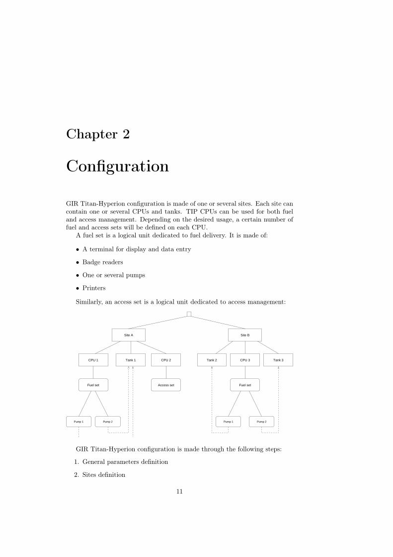
GIR Titan-Hyperion configuration is made of one or several sites. Each site cancontain one or several CPUs and tanks. TIP CPUs can be used for both fueland access management. Depending on the desired usage, a certain number offuel and access sets will be defined on each CPU.
A fuel set is a logical unit dedicated to fuel delivery. It is made of:
• A terminal for display and data entry
• Badge readers
• One or several pumps
• Printers
Similarly, an access set is a logical unit dedicated to access management:
Site BSite A
CPU 1 CPU 2 CPU 3Tank 1
Fuel set
Pump 2Pump 1
Access set
Tank 2 Tank 3
Fuel set
Pump 2Pump 1
GIR Titan-Hyperion configuration is made through the following steps:
1. General parameters definition
2. Sites definition
11

12 CHAPTER 2. CONFIGURATION
3. Tanks definition
4. CPUs definition, with for each CPU:
• Modules creation
• Modules aggregation into a fuel set or access set
2.1 General parameters
2.1.1 Installer config.B Config., Installer config.
First id: Defines the first item asked when entering a manual transaction (Vehicleor Driver). It is recommanded to use the same identification order as onCPUs.
General options:
• Enable proxi. file.: This option should be enabled when the badgesused are GIR proximity badges. It allows to initialize badges usinga proximity file. See the “Data entry” chapter in the user manual formore information.
• Local zones: Enables local zones management. This adds the Localzone field in fuel and access sets, and tabs in vehicles and driverssheets. See the user manual for more information.
• Vehicle badge on 16 , Driver badge on 16 , Nick on 20 : Increases thesize of the corresponding fields.
• Data import by manager : Allows the manager to use initial data im-port.
• Disable ext. tr. export: Don’t export external fuelings.
CPUs options:
• Code + Secret code vehicles, Code + Secret code drivers: These op-tions allow to enter a secret code in addition to the identification forvehicles and drivers. See the “Data entry” chapter in the user manualfor more information.
• Numerical drivers code: This option allows to keep a 6-digits drivercode when using the Code + Secret code drivers mode (TIP1-Pabbayonly).
• Force driver id. by code, Force vehicle id. by code: Forces code iden-tification for all vehicles (resp. drivers), ignoring their individualconfiguration.
• Vehicle auth. by direction: Allows to define direction-based vehiclesauthorizations for drivers, instead of department-based authoriza-tions.
• Show cons. graph.: Displays over and under-consumption on the CPU(TIP2-Vatersay only, when consumption display is enabled).
2.1. GENERAL PARAMETERS 13
• 16 products max.: Limit the total number of products in the softwareto 16. This speeds up data processing on large databases.
• Per-driver language: Shows the CPU language field in drivers, tochange the CPU language when a driver is identified (TIP2-Vatersayonly).
Config. options:
• Ignore modified config. on tanks tresholds: Don’t set CPUs to the“modified config.” state when the alert treshold is modified. Thealert treshold on CPUs is only use for live printing.
Real-time tempo: Defines real-time dialogues frequency. The higher the fre-quency is, the faster the transactions are retrieved. However, when trans-actions are very frequent, the application can become less available forusers.
Real-time opt.:
• Retr. seule: Only use real-time dialogues for transaction retrieval. Ifso, data sending should be definine using auto. progs.
Authorizations v/d: Defines the mode to use for authorization of vehicles todrivers: by department, direction, or departments group.
Hour meters unit (TIP) : Defines the entry unit for hour meters on TIP CPUs:1/100H, 1/10H or H.
TIP CPUs messages section: These fields change the messages displayed onTIP CPUs.
GC90 CPUs messages section: These fields change the messages displayed onGC90 CPUs.
Terminology section: These fields change the terms used in the software.
2.1.2 ProductsB Config., Products
Nom: Name used to refer to a product in the software and on CPU.
Ref.: Value used to refer to a product in specific exports.
P.U. min., P.U. max.: Unit price validity range for this product. It is usedwhen entering a tank supply or a manual transaction, to control the valueof the entered data, for example to avoid an inversion between volume andunit price.
Sale unit, Sale unit name: Value and name of the sale unit for this product.When these values are defined, an additionnal column is displayed in thetanks state.
Type: Product type (Fuel , Washing , Other), used to filter transactions in theirhistory.
14 CHAPTER 2. CONFIGURATION
Options:
• Disable traclient export: Causes transactions with this product to beignored in traclient exports.
2.1.3 Access typesB Config., Access types
Name: Name used to refer to an access type in the software.
Ref: Value used to refer to an access type in specific exports.
Character: Character used to identify an access type on the live printer (TIP2-Vatersay only).
Source state name: For bistable accesses, name of the system state before thisaccess type is done (e.g. “Enabled” or “Disabled” for an alarm). Thesenames are displayed in the supervision screen (TIP2-Vatersay only).
2.2 SitesB Config., Sites
Short name, Full name: Names used to refer to a site in the software.
Ref.: Value used to refer to a site in specific exports.
Region: Assigned region (Only when the corresponding feature is enabled inthe Manager config.).
2.3 TanksB Config., Tanks
Site: Related site.
Short name, Full name: Names used to refer to a tank in the software.
Ref.: Value used to refer to a tank in specific exports.
Product: Tank’s product
Blocking treshold: Stock below which the pumps using this tank are automat-ically blocked.
Alert treshold: Stock below which an alert is generated.
Current stock, U.P.: Current tank stock and unit price of this stock. Thosevalues can’t be modified directly. After creating a tank, they must beset by entering a supply (See the “Operations entry” chapter in the usermanual).
Capacity: Total tank capacity.
2.4. CPUS 15
Compartments: Compartments contain a tank’s gauging configuration. Upto 4 independant compartments can be defined for each tank. When atank has a gauge and only one compartment, compartment 1 should beused.
Each compartment has the following fields:
Mod. 232 gauge: Gauge module associated to the compartment (the module and theCPU must have been previously created).
Gauge type, Probe num.: Gauge settings.
Capacity: Compartment capacity.
Offset: Offset used to shift heights read by the gauge module.
Options:
– Computed by Hyperion: Forces the volume to be computed bythe software when retrieving gauging data. When this option isenabled, the only values used from the gauge are the fuel height,the water height, and the temperature.
Gauges alerts, Gauges options: Alert generation tresholds (See the “Configu-ration” section of the “Data entry” chapter, in the user manual).
When a tank has a gauge module, it is also necessary to fill the associatedabacuses table, in the tank sheet.
→ Conventions:
• Tanks names: Tank 1, Tank 2, . . .
• Blocking treshold: Empty by default (no blocking).
• Alert treshold: 0 L by default.
Note: When a tank name is displayed, the name of its product is automat-ically appended. Hence, it is not necessery to repeat the product name in thetank name.
2.4 CPUs
B Config., CPUs
Num.: Number automatically assigned to each CPU by GIR Titan-Hyperion.It is unique to each CPU.
Site: CPU site.
Short name, Full name: Names used to refer to the CPU in the software.
Ref.: Value used to refer to a CPU in specific exports.
Adr.: CPU address.
16 CHAPTER 2. CONFIGURATION
Password: (TIP2-Vatersay only) Defines the password to use during dialogueswith this CPU. It must have been previously set in the CPU configurationmenu.
Type: CPU type and link. The CPU type depends on the management unitused. For old hardware, some software features might not be available.GIR Titan-Hyperion supports the following models:
• GC90 : Old hardware, supported for compatibility.
• TIP1-Pabbay : Intermediate hardware, most features available.
• TIP2-Vatersay : New hardware, all features available.
The link defines the performance of communications between PC andCPU. Some links are only available for a specific cpu type. The followingconfigurations are available:
• net: full TCP networking
• 232 : 57600 bauds, full-duplex
• 485 : 57600 bauds, half-duplex
• x19 : 19200 bauds, half-duplex
• x9 : 9600 bauds, half-duplex
Link type: PC-CPU link type: network, serial or modem.
Link param.: Link parameters. Their parsing by GIR Titan-Hyperion dependson the link type:
• TCP : <host>:<port>. The host name may be an IP address or aDNS name (e.g. 192.168.0.123:6001).
• Serial : <comX> where X is a serial port number (e.g. com1).
• Modem: <comX>:<tel>[:<atdt>[:<at&f>]] where X is the serialport on which the modem is connected, and tel is the phone numberto dial (e.g. com2:0478741234). The successive commands sent tothe modem are:
1. atz2. Command specified in the fourth parameter (at&f by default)3. Command specified in the third parameter followed by the phone
number (atdt by default)
Mode: Synchronisation mode between GIR Titan-Hyperion and the CPU (TIPCPUs only).
• Autonomous: Connection with the CPU is temporarily establishedduring dialogues, which can be manually or automatically launched.
• Real time: Connection with the CPU is permanent. Transactions areretrieved in real time by the software, and data is regularly synchro-nized.

2.4. CPUS 17
• Autonomous without auto. conn.: Identical to the autonomous mode,except for the supervision screen where the user must explicitly askfor the connection to the CPU.
Sequence file: Name of the sequence file to use. The sequence files are searchedin the seq sub-directory. The sequence file to use can be chosen among alist of the available files, in B Config., Sequence update.
Language: Defines the language to use one the CPU. By default, the languageused is the same as in the software.
Timezone: Defines the CPU timezone, if it differs from the software timezone.
Options:
• Forbidden: Disables a cpu without deleting it.
In addition to those settings, a CPU is made of multiple modules, assembledinto fuel or access sets. Modules and sets are available using the different tabsin the CPU sheet. The General tab displays a summary of the configuration.
→ Conventions:
• CPUs names: CPU 1, CPU 2, . . .
2.4.1 PumpsIO num.: Module address (from 0 to 15)
Name: Pump name, used to refer to the pump in the software, and displayedon the terminal, on the pump selection confirmation screen.
Ref.: Value used to refer to a pump in specific exports.
Product: Product delivered by the pump.
Tank 1, Tank 2: Tanks in which the pump takes fuel. The first tank is manda-tory, except for fake pumps (see below). The second tank should be setonly for mixed products.
Ratio: When two tanks are defined, indicates the product percentage takenfrom tank 2.
Start T.: Delivery starting temporization (see below).
End T.: Delivery ending temporization (see below).
Counter:
• Simple: One counting channel• Double: Two counting channels• Bidirectional : Two counting channels, counting positively or nega-
tively given the pulses order.• Double (Add): Two counting channels, adding the pulses count on
both channels.
18 CHAPTER 2. CONFIGURATION
• Simple (Up+Down): One counting channel, on ascending and de-scending fronts (doubles the number of pulses).
• Double (Up+Down): Two counting channels, on ascending and de-scending fronts (doubles the number of pulses).
Hangup:
• On opening : Contact is opened when the pump nozzle is hanged up.• On closing : Contact is closed when the pump nozzle is hanged up.• Auto: The hangup type is automatically detected during the first
fueling.
Tops: Number of tops per liter for the counting device (from 1 to 10 000).
Coefficient: Coefficient to apply when sending a tops per liter value to theCPU. This is usefull to customize the range of available values for specificconfigurations (See 2.5, page 27). When such a coefficient is defined, thevolume displayed on the terminal is not the real volume.
Type: Pump type
• Delivery : Pump used for fuel delivery. The volume measured is de-ducted from the stock of the associated tank.
• Decanting : Decanting pump. A transaction done on this pump willbe stored with a negative volume and the tank stock will be increasedinstead of decreased.
• Fake: Allows to use a pump module to control other devices (e.g. ina washing station). A fake pump must not be related to any tank. Atransaction done on this pump won’t deduct any stock, and will beassigned a 1 liter volume.
• Vol. enterd on CPU: Fake pump, with manual entry of the volume onthe CPU terminal.
• No tank : Pump without an assigned tank (e.g. washing).
Max. duration (normal), Max. duration (restrict.): Maximum transaction du-ration, under normal and restricted modes (TIP2-Vatersay only, see be-low). Zero means “Unlimited”.
Options:
• Forbidden in restricted mode: Makes the pumps unavailable underrestricted mode (TIP2-Vatersay only).
Totalizer: See user manual.
→ Conventions:
• Pumps names (unless the customer uses a specific convention): Pump 1,Pump 2, . . .
Note: When a pump name is displayed, either on the terminal or in thesoftware, its product name is automatically appended. Hence, it is not necessaryto repeat the product name in the pump name.
2.4. CPUS 19
Temporizations and max. duration
The Start T., End T. and Max. duration fields define how a transaction is tem-porized.
Start T. is the time after which a transaction is stopped if no fuel has beendelivered since the pump was commanded. End T. is the time after which atransaction is stopped if no fuel has been delivered once a first fueling wasdetected. Those temporizations are detailed in the “CPU usage” chapter of theuser manual.
Max. duration is the maximum time that a transaction can take, it is thesame whether fuel is taken or not. For TIP1-Pabbay CPUs, it is defined inthe fuel set. For TIP2-Vatersay CPUs, it is defined per pump, and can changeunder restricted mode.
For all cases, a zero value means that the associated temporization is unlim-ited.
Washing station: These temporizations can be used to control the washingduration on a washing station.
For TIP1-Pabbay CPUs, the maximum duration has an influence on all thepumps of a given set. The washing duration should then be defined by thedelivery starting temporization.
For TIP2-Vatersay CPUs, it is recommanded to use the Max duration field,which is pump-specific.
2.4.2 Terminals
IO num.: Module address (from 0 to 15)
Nom: Module name
Keyboard: Keyboard type. For TIP CPUs, the valid keyboard types are TIP,GIR 12 keys and SECME .
Password char.: Character displayed on the terminal when a code is entered.
End T.: Entry ending temporization: inactivity timeout after which an entryis automatically cancelled.
Options:
• 40 columns, 4 lines: Terminal display format. Standard TIP termi-nals have 20 columns and 2 lines.
→ Conventions:
• Modules names: x-Term 1, x-Term 2, . . .
Where x is the letter of the set in which the terminal is being used.

20 CHAPTER 2. CONFIGURATION
2.4.3 ReadersThe modules defined in the Readers tab are GIR proximity badges readers. Theycan also be used to control an access point. Other badges readers are definedusing 232 modules.
IO num.: Module address (from 0 to 15)
Name: Module name
Type: Reader type (Marin 125 kHz by default)
→ Conventions:
• Reader modules names: x-Prox 1, x-Prox 2, . . .
• Reader modules names when used as access control: x-Relay 1, x-Relay2, . . .
Where x is the letter of the set in which the reader is being used.
2.4.4 4I4OModules “4 inputs 4 outputs”.
IO num.: Module address (from 0 to 15)
Name: Module name
→ Conventions:
• Modules names: x-4I4O 1, x-4I4O 2, . . .
Where x is the letter of the set in which the module is being used.
2.4.5 232 modules232 modules provide an interface to a RS-232 device. They can be used to covera large variety of needs: reader, printer, gauge . . .
IO num.: Module address (from 0 to 15). For TIP2-Vatersay CPUs, values 16to 31 are also valid, and allow to use a USB/RS-232 converter directlyplugged to the management unit. The adress/port map is detailled inappendix to this document.
Name: Module name
Speed, Format, Stop bits: Parameters of the serial connection.
Options:
• CR: Adds a carriage return character (\’r’) at the end of strings sent,and removes it at the end of strings received (TIP1-Pabbay only).
The configuration to use on 232 modules for different devices is detailed inappendix to this document.

2.4. CPUS 21
→ Conventions:
• Names of readers modules: x-Rdr 1, x-Rdr 2, . . . where x is the letterof the set in which the reader is being used.
• Names of printer modules: Print 1, Print 2, . . . for shared printers.x-Print 1, x-Print 2, . . . for printers assigned to a single set, where xis the letter of the set.
• Names of gauge modules: Gauge 1, Gauge 2, . . .
2.4.6 Fuel sets
Fuel set TerminalPrinters
Proximity readerSpecific reader
Pump 2Pump 1 Pump 3
IO num.: Fuel set number
Name: Fuel set name
Terminal: Fuel set terminal module.
First id: Defines the first identification (Vehicle or Driver) asked before a fueling.
GIR proxi reader, Spec. reader 1, Spec. reader 2: GIR proximity reader andspecific readers. Specific readers must be associated to badges formats andidentifiers (See 2.6, page 27). If those three readers are (N/A), only theidentification by code will be available.
Spec. 1 type, Spec. 2 type: Special badges management (TIP2-Vatersay only).Special badges types are detailled in appendix to this document.
Opt. proxi., Opt. spec. 1, Opt. spec. 2: • Disabled on vehicle id., Disabledon driver id.: Disables the reader in the corresponding identificationcontext.
• Debug id.: For special badges, enables logging of detailled informationin the CPU Logs.
22 CHAPTER 2. CONFIGURATION
First pump, Last pump: Pumps related to the fuel set. All pump moduleswith an IO num. between those of the selected pumps will be consideredas members of the fuel set.
Min. time null vol.: Minimum transaction duration to consider it as a null vol-ume.
Null vol. before block.: Number of consecutive null volumes before blocking apump.
Live printer: 232 module for the live printer
Ticket printer: 232 module for the ticket printer
Ticket begin, Ticket end: Ticket printer control strings (ascii-hexa), sent re-spectively before and after the ticket data.
Show volume: Displays the volume on the terminal during the delivery. (N/A)means “no display”.
Vol. duration: Volume display duration at the end of a transaction (TIP2-Vatersay only).
Cons. duration: Consumption display durationn at the end of a transaction(TIP2-Vatersay only).
Max. duration: Maximum transaction duration. Zero means “unlimited” (TIP1-Pabbay only, see 2.4.1, page 19)
Time offset: Defines an offset to apply when a date is read on a badge (TIP2-Vatersay with special badges only).
Anonymous tacho. downl. freq: Download frequency for tachograph cards down-loaded anonymously.
Options:
• Show last meter : Displays the last known meter when prompting fora new meter.
• Log auth. failures: Creates transactions on access denied errors (un-known badge, forbidden vehicle, . . . ).
• Ignore blocking maintenances: When enabled, the vehicles that areforbidden because of a maintenance undone, won’t be blocked onthis CPU. The other forbidding causes (manual fobidding, expiry)remain applicable. For TIP1-Pabbay CPUs, this option must havethe same value (either set or unset) for all the fuel sets of a givenCPU.
• Print codes: Prints codes on live and ticket printers, even when theyare used for identification.
• Display vehicles codes (resp. driver): Shows clear-test codes on theterminal during an entry (TIP2-Vatersay only).
2.4. CPUS 23
• Force vehicle id. by code (resp. driver): Allows code identificationfor vehicles that are configured with a badge identification (TIP2-Vatersay only).
• Force pump selection: Shows the pump selection screen even whenthe fuel set has only one pump (TIP2-Vatersay only).
• Ignore cons. display : Never display consumption at the end of atransaction (TIP2-Vatersay only).
• Show badge init. menu: Shows the badge initialization menu in theattendant menu (TIP2-Vatersay only).
• Any vehicle badge, Any driver badge: Allows fueling when a badge isnot defined in the database. In that case, the badge code is stored inthe transaction specific code.
• USB storage: Records fuel transactions to a csv file on a USB keyplugged to the CPU (TIP2-Vatersay only).
• Tacho download : Enables data download on tachograph cards (TIP2-Vatersay only).
Zone, Local zone: Zones associated to the fuel set. For more information onzones, see, the “Data entry” chapter in the user manual.
Restr. zone, Local restr. zone: Restricted mode zones (TIP2-Vatersay only).For more information on the restricted mode, see the “CPU usage” chapterin the user manual.
→ Conventions:
• A fuel set is named by an uppercase letter, starting form A.
• When a fuel set is integrated into a single pump, it should be named x-FSPn, where x is the fuel set letter, and n the pump number. Example: A-FSP1, B-FS P2, . . .
• Fuelsets containing several pumps should be named x-FS 1, x-FS 2, . . .where x is the fuel set letter.

24 CHAPTER 2. CONFIGURATION
2.4.7 Access sets
ContactinputPrinter
Proximity readerSpecific reader
Prealarmcommand
Access set
Lockcommand
Alarmcommand
IO num.: Access set number
Name: Access set name
Type: Access type
Alt. type: Alternative access type (TIP2-Vatersay only). Its usage depends onthe Mode field.
Terminal: Access set terminal module (TIP2-Vatersay only).
Mode: Access set mode (TIP2-Vatersay only):
• Standard : Single command, Alt. type unused.• Type+Alt. type/1 command : Alternation between Type and Alt. type,
with a single command.• Type+Alt. type/2 commands: Alternation between Type and Alt.
type, with a two commands. Transactions of the first type commandthe module defined in Lock read., and transactions of the second typecommand the module defined in Alarm read..
GIR proxi reader, Spec. reader 1, Spec. reader 2: GIR proximity reader andspecific readers. Specific readers must be associated to badges formats andidentifiers (See 2.6, page 27).
Spec. 1 type, Spec. 2 type: Special badges management (TIP2-Vatersay only)Special badges types are detailled in appendix to this document.
Identification: Defines the identifications to be asked. At least one identifica-tion (Vehicle or Driver) must be defined, except when forced zones aredefined in the set.
Lock read., Lock 4I4O, Channel num., Com. duration: Reader or 4I4O mod-ule for the lock command, and command duration. For 4I4O modules, thechannel number must also be set.

2.4. CPUS 25
Contact read., Contact 4I4O, Channel num.: Reader or 4I4O module for theinput contact. For 4I4O modules, the channel number must also be set.
Alarm read., Alarm 4I4O, Channel num., Com. duration: Reader or 4I4O mod-ule for the alarm command, and command duration. For 4I4O modules,the channel number must also be set.
Preal. read., Preal. 4I4O, Channel num., Com. duration: Reader or 4I4O mod-ule for the pre-alarm command, and command duration. For 4I4O mod-ules, the channel number must also be set.
T1: Opening time before triggering the alarm.
T2: Time after which the pre-alarm is triggered on non-opening. T2 must belower than T1.
T3: Time after which the pre-alarm is triggered on non-closing. T3 must belower than T1.
Live printer: 232 module for the live printer
Options:
• Log auth. failure: Creates transactions on access denied errors (un-known badge, forbidden vehicle, . . . ).
• Reversed contact: Inverts the input contact. By default, the door isconsidered as closed when the contact is closed. When this option isenabled, the door is considered as closed when the contact is opened.
• Access forbidden on full memory : Forbids the access when no moretransaction can be stored.
• Monoled reader : Replaces the red LED lighting by a flash on thegreen LED on GIR proximity readers (TIP2-Vatersay only).
• Punctual remote command , Forced remote command : Allows remotecommand of this access set. See the “Access management” chapterin the user manual for more information.
• Force code id.: Allows code identification even for vehicles or driversconfigured with a badge identification (TIP2-Vatersay only).
• USB storage: Records access transactions to a csv file on a USB keyplugged to the CPU (TIP2-Vatersay only).
Alarme:
• On forced open: Triggers the alarm when an opening is detected butthat the lock has not been commanded.
• On no open: Triggers the alarm when opening is not detected T1seconds after the lock has been commanded.
• On no close: Triggers the alarm when closing is not detected T1seconds after the lock has been commanded.
Zone: Zones associated to the access set. For more information on zones, see,the “Data entry” chapter in the user manual.

26 CHAPTER 2. CONFIGURATION
Forced zone: When forced zones are defined, the lock is commanded during allthe corresponding timeslots. This allows to leave an access point openedat a fixed hour.
Local zone, Loc. forced zone: Identical to the fields above, for local zones.
→ Conventions:
• An access set is named by a lowercase letter, starting from a.
• When possible, access sets should be named explicitly from the location ofthe access point. This name should start by the access set letter followedby a hyphen: a-Entrance, b-Station, c-Room, . . .
• Otherwise, the name should be x-Access 1, x-Access 2, . . . where x isthe access set letter.
2.4.8 Configuration validityGIR Titan-Hyperion does validity controls on CPUs configuration. The resultof these controls is displayed under the General tab:
Green square, Valid configuration: The configuration is valid and can besent to the CPU.
Req square, Invalid configuration: The configuration contains errors, whichare displayed in red next to the corresponding element, under the Generaltab.
Here are some of the validity controls:
• Presence and validity of the sequence file
• Validity and non-overlapping of IO numbers
• Number of zones (8 max. per CPU)
• The terminal, pump and reader modules can be used only once, in a singleset.
• Number of tanks (16 max. per CPU)
• The tanks associated to a CPU must refer to the same site as the CPU.
• In a fuel set, the IO num. of the first pump must be lower than the numberof the last pump, and all intermediate numbers must be defined.
• In an access set, at least one reader and one identification type must bedefined, unless there are forced zones.
• In an access set, there must be a command with a defined duration.
• In an access set, T2 ≤ T1 and T3 ≤ T1.
Orphan modules (defined, but not related to a set) are not errors, but theyare displayed as warnings under the General tab.

2.6. SPECIFIC BADGES 27
2.5 Values rangeThis section lists the available values ranges for volumes, on TIP CPUs.
Legend: K=1 000, M=1 000 000, G=1 000 000 000
• Without a coefficient:
TIPValue Min Max PrecTops/L 1 10K 1 (*)Transac. 0 L 167 KL 0.01Capacity 0 L 32 KL (**) 1Credit 0 L 16 ML 1Stock -2.1 GL 2.1 GL 1Totaliz. 0 L 1 ML 1
– (*) Variable precision depends on the value: 1 up to 100 tops/L, 4at 200 tops/L, 25 at 500 tops/L.
– (**) A special “infinite” capacity is also supported.
• With a *10 coefficient:
TIPValue Min Max PrecTops/L 0.1 1K 0.1Transac. 0 1.6M 0.1Capacity 0 320K 10Credit 0 160M 10Stock -21G 21G 10Totaliz. 0 10M 10
• With a /10 coefficient:
TIPValue Min Max PrecTops/L 10 100K 10Transac. 0 16K 0.01Capacitu 0 3K 0.1Credit 0 1.6M 0.1Stock -210M 210M 0.1Totaliz. 0 100K 0.1
2.6 Specific badgesThe specific badges configuration is done by the Badges formats and Badgestypes tables in the B Config. menu.
When using a specific badge, the CPU receives a characters string via a232 module. The Badges formats table allows to define how this string will bedecoded.

28 CHAPTER 2. CONFIGURATION
Name: Format name
Reader: Type of the reader on which the badge is read (Type 1 when the readeris defined as specific reader 1 in a fuel or access set, Type 2 in the othercase).
Synchro. string: Defines a string to match into the read string.
Control char.: Adds control characters before (STX) or after (ETX or CR) thesynchronisation string.
Length: Defines a filter on the length of the string read ((N/A): no filter). Thelength is counted from the first character following the synchronizationstring, and includes the termination characters when applicable (e.g. acarriage return).
Id. pos., Id. length: Position and length of the identifier. Position 1 matchesthe first character after the synchronization string (first character of thewhole string when the synchronization string is empty).
Num. pos., Num. length: Position and length of the badge number.
To check how a badge will be decoded, enter the raw string in the text fieldof the badge format sheet, then click on View.
A specific badge is made of two parts: the identifier and the number.
• The number corresponds to a single badge, and must be defined in theBadge code field of the vehicle or driver identified by this badge. (See the“Data entry” chapter in the user manual).
• The identifier is the same for a whole badges group. Allowed identifiersmust be defined in the Badges types table.
The Badges types table contains the following information:
Num.: Number automatically assigned to each identifier by GIR Titan-Hyperion.
Name: Identifier name.
Reader: Type of the reader on which badges using this identifier are read. Itmust be the same as the reader type defined in the associated badge for-mat.
Identifier: Identifier code.
Spec. process., Parameters: Defines a pre-processing to apply to a badge codebefore it is sent to the CPU. Pre-processings configuration is detailed forseveral badge types in appendix to this document.
Post-processing, Parameters: Defines a processing to apply to a badge codeafter it is read and before it is searched in the database (TIP2-Vatersayonly).
File id: String used to build the name of proximity files:
data\dti\pros-<id>-*.txt

2.6. SPECIFIC BADGES 29
Options:
• Enable proxi. file: Enables proximity files management for vehiclesand drivers using this identifier. The principle is identical to the oneused for GIR proximity files, and allows to simplify the associationbetween the number written on a badge and its chip code (See 2.1.1,page 12).
When a specific badge is read and that it can’t be resolved to an identifierusing the defined badges formats and types, the BADGE NOT RECOGN. messageappears. When matching format and identifier are found, but that the badgenumber does not exist, the UNKNOWN BADGE message is displayed.
In both cases, if the Log auth. failures option is enabled in the fuel or accessset containing the reader, a transaction with the read string will be created.These transactions are processed by GIR Titan-Hyperion and stored in theEvents table, under the Invalid badge type.
The main formats of specific badges are detailed in appendix to this docu-ment.

30 CHAPTER 2. CONFIGURATION

Chapter 3
CPU communication
3.1 Configuration sendingSeveral operations are available in the B CPU comm. menu to initialize a CPUwith a new sequence, and send the configuration.
• Retr.-Init.-Config.-Send first retrieves the transactions that are stored onthe CPU, then performs a full initialization.
• Init.-Config.-Send is identical to the above except that it doesn’t retrievetransactions before doing an initialization. For this reason, it should beused with caution. Actually, it should only be used on the first time aCPU is initialized, or when it contains invalid data.
• Retr.-Config.-Send : Once a CPU has been correctly initialized with thedesired sequence, this operation should be used to update its configuration.
See the “CPU communication” chapter in the user manual for more infor-mation.
3.2 Addressing optionsThe Broadcast adressing mode allows to communicate with a CPU no matterwhat its address is. When several CPUs are defined on the same interface (e.g.when using RS-485), this mode can only be used if a single CPU is active (i.e.powered on and connected to the network).
The Undef addressing mode allows to communicate with a CPU when itsaddress has been lost after an interrupted initialization (TIP1-Pabbay only).
31

32 CHAPTER 3. CPU COMMUNICATION
Appendix A
Link test files content
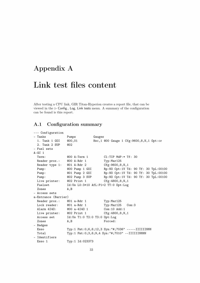
After testing a CPU link, GIR Titan-Hyperion creates a report file, that can beviewed in the B Config., Log, Link tests menu. A summary of the configurationcan be found is this report.
A.1 Configuration summary
--- Configuration- Tanks Pumps Gauges1. Tank 1 GOI @00,01 Hec,1 @00 Gauge 1 Cfg:9600,8,N,1 Opt:cr2. Tank 2 SUP @02
- Fuel setsA-GC 1Term: @00 A-Term 1 Cl:TIP MdP:* Tf: 30Reader prox.: @00 A-Rdr 1 Typ:Mar125Reader type 1: @01 A-Rdr 2 Cfg:9600,8,N,1Pump: @00 Pump 1 GOI Rp:NO Cpt:1V Td: 90 Tf: 30 TpL:00100Pump: @01 Pump 2 GOI Rp:NO Cpt:1V Td: 90 Tf: 30 TpL:00100Pump: @02 Pump 3 SUP Rp:NO Cpt:1V Td: 90 Tf: 30 TpL:00100Live printer: @02 Print 1 Cfg:4800,8,N,1Fuelset Id:Us L0:3*10 AfL:P1+2 TT:0 Opt:LogZones A,B
- Access setsa-Entrance (Barrier)Reader prox.: @01 a-Rdr 1 Typ:Mar125Lock reader: @01 a-Rdr 1 Typ:Mar125 Com:3Alarm 4I4O: @00 a-4I4O 1 Com:10 Add:1Live printer: @02 Print 1 Cfg:4800,8,N,1Access set Id:Us T1:0 T2:0 T3:0 Opt:LogZones A,B Forced:
- BadgesEsso Typ:1 Fmt:0;6,6;12,3 Syn:"#;7036" -----IIIIIINNNTotal Typ:1 Fmt:0;3,6;9,4 Syn:"#;7010" --IIIIIINNNN
- IdentifiersEsso 1 Typ:1 Id:023373
33
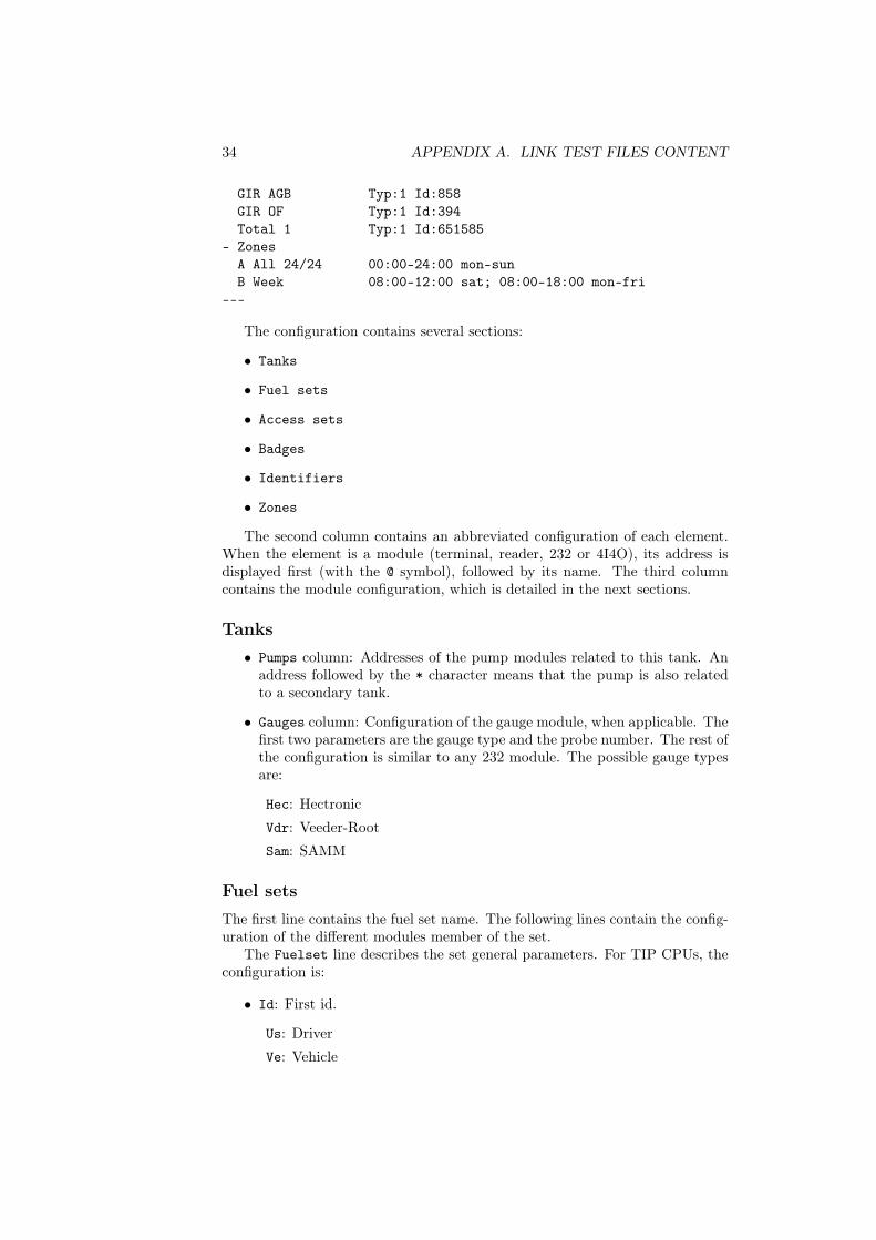
34 APPENDIX A. LINK TEST FILES CONTENT
GIR AGB Typ:1 Id:858GIR OF Typ:1 Id:394Total 1 Typ:1 Id:651585
- ZonesA All 24/24 00:00-24:00 mon-sunB Week 08:00-12:00 sat; 08:00-18:00 mon-fri
---
The configuration contains several sections:
• Tanks
• Fuel sets
• Access sets
• Badges
• Identifiers
• Zones
The second column contains an abbreviated configuration of each element.When the element is a module (terminal, reader, 232 or 4I4O), its address isdisplayed first (with the @ symbol), followed by its name. The third columncontains the module configuration, which is detailed in the next sections.
Tanks• Pumps column: Addresses of the pump modules related to this tank. An
address followed by the * character means that the pump is also relatedto a secondary tank.
• Gauges column: Configuration of the gauge module, when applicable. Thefirst two parameters are the gauge type and the probe number. The rest ofthe configuration is similar to any 232 module. The possible gauge typesare:
Hec: Hectronic
Vdr: Veeder-Root
Sam: SAMM
Fuel setsThe first line contains the fuel set name. The following lines contain the config-uration of the different modules member of the set.
The Fuelset line describes the set general parameters. For TIP CPUs, theconfiguration is:
• Id: First id.
Us: Driver
Ve: Vehicle
A.1. CONFIGURATION SUMMARY 35
• L0: Null volume option, under the form N*T where N is the number of con-secutive null volumes causing the pump to be blocked, and T the minimumduration of a transaction to be counted as a null volume.
• AfL: Delivered volume display
P1: First pump
P1+2: Two first pumps
• TT: Max. transaction duration.
• Opt: Options
AfK: Show the last known meter
Log: Log auth. failures
Mtn: Maintenances only
The Zones line describes the different zones in which the set appears.
Access set
The first line contains the access set name. The following lines contain theconfiguration of the different modules member of the set.
The Access set line describes the set general parameters. For TIP CPUs,the configuration is:
• Id: First identification
Us: Driver
Ve: Vehicle
• T1,T2,T3: Alarm temporizations (See 2.4.7, page 24).
• Opt: Options
Log: Log auth. failures
Inv: Reversed contact
Mem: Access forbidden on full memory
• Alm: Alarm options
OF: On forced open
NO: On no open
NF: On no close
The Zones line lists the zone in which the set appears. Forced lists theforced zones.
36 APPENDIX A. LINK TEST FILES CONTENT
Badges formats• Format name.
• Typ: Associated reader type (1 or 2).
• Fmt: Format parameters: total length, identifier position, identifier length,number position, number length.
• Syn: Synchronization string, between quotes.
• Format schematic.
Identifiants• Identifier name.
• Typ: Associated reader type (1 or 2).
• Id: Identifier code.
• Spe: Specific processing.
--: None
HID1: HID H10301, 125 KHz, 26 bits format
HID2: HID, 125 KHz, 30 bits format
ZERO: Zero padding
• Par: Specific processing parameters
• Prx: Proxi file name (when enabled)
Zones• Letter and name of the zone.
• Time slots.
Pump modules• Rp: Hangup type
--: None
Au: Automatic
NO: On opening
NF: On closing
• Cpt: Counter type
1V: Simple
2V: Double
C/D: Bidirectionnal
2vi: Double (Add)

A.1. CONFIGURATION SUMMARY 37
1UD: Simple (Up+Down)
2UD: Double (Up+Down)
• Td: Delivery starting temporization, in seconds
• Tf: Delivery ending temporization, in seconds
• TpL: Tops per liter
• Opt: Options
Fic: Fake pump
232 modules
• Cfg: 4 comma-separated parameters: speed in bauds, number of data bits(7 or 8), parity, number of stop bits. Parity can be one of:
N: None
E: Even
O: Odd
• Opt: Options
cr: Carriage return option
Reader modules
• Typ: Reader type.
Mar120: Marin 120 KHz
Mar125: Marin 125 KHz
Mar125-alt: Marin 125 KHz alternative
Mar130: Marin 130 KHz
Additionnal parameter when the module is used as a command in an accessset:
• Com: Command duration
4I4O modules
Additionnal parameters when the module is used as a relay in an access set:
• Com: Command duration
• Add: Channel number
38 APPENDIX A. LINK TEST FILES CONTENT
Terminal modules• Cl: Keyboard type, one of: GIR, TIP, GTA, SECME, ASCII
• MdP: Password character
• Tf: Entry ending temporization, in seconds
• Opt: Options
40c: 40 columns
4l: 4 lines
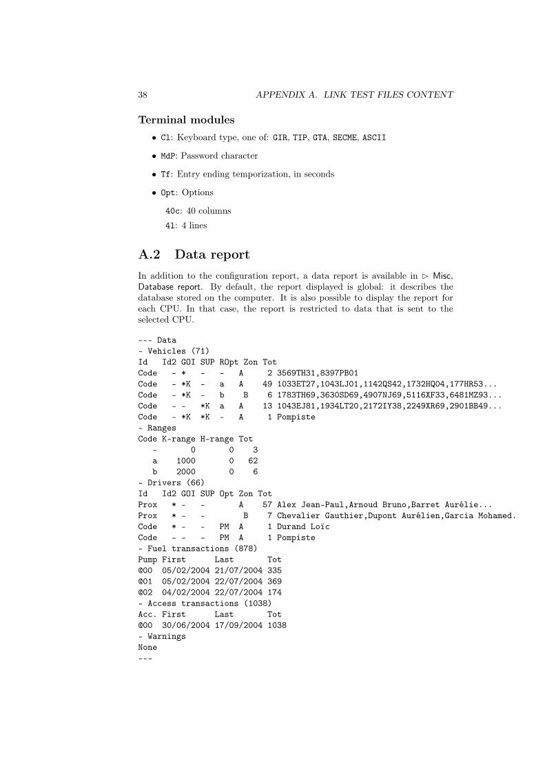
A.2 Data reportIn addition to the configuration report, a data report is available in B Misc,Database report. By default, the report displayed is global: it describes thedatabase stored on the computer. It is also possible to display the report foreach CPU. In that case, the report is restricted to data that is sent to theselected CPU.
--- Data- Vehicles (71)Id Id2 GOI SUP ROpt Zon TotCode - * - - A 2 3569TH31,8397PB01Code - *K - a A 49 1033ET27,1043LJ01,1142QS42,1732HQ04,177HR53...Code - *K - b B 6 1783TH69,3630SD69,4907NJ69,5116XF33,6481MZ93...Code - - *K a A 13 1043EJ81,1934LT20,2172IY38,2249XR69,2901BB49...Code - *K *K - A 1 Pompiste- RangesCode K-range H-range Tot
- 0 0 3a 1000 0 62b 2000 0 6
- Drivers (66)Id Id2 GOI SUP Opt Zon TotProx * - - A 57 Alex Jean-Paul,Arnoud Bruno,Barret Aurélie...Prox * - - B 7 Chevalier Gauthier,Dupont Aurélien,Garcia Mohamed.Code * - - PM A 1 Durand LoïcCode - - - PM A 1 Pompiste- Fuel transactions (878)Pump First Last Tot@00 05/02/2004 21/07/2004 335@01 05/02/2004 22/07/2004 369@02 04/02/2004 22/07/2004 174- Access transactions (1038)Acc. First Last Tot@00 30/06/2004 17/09/2004 1038- WarningsNone---
A.2. DATA REPORT 39
This report contains the following sections:
• Vehicles
• Ranges: Tolerance range four milometers and hour meters
• Drivers
• Fuel transactions: Fuel transactions retrieved from this CPU.
• Access transactions: Access transactions retrieved from this CPU.
• Warnings: Warnings generated when sending data to this CPU.
Vehicles and drivers are classified among several categories, based on thefollowing criteria:
• Id: Identification method.
– Code: Code identification
– Prox: GIR proximity badge identification
– Id#NN: Specific badge number NN identification (This is the Num.field of the Badges types table).
– (N/A): No identification (empty badge and code)
– Init: Identification with badge initialization
– Att.: Attendant only identification
• Id2: Second identification (i.e. Driver id. for vehicles, and Vehicle id. fordrivers).
– -: No second identication
– *: Asks for second identication
• Authorized products and meters (vehicles only).
– -: Product forbidden
– *: Product authorized
– Q: Product authorized, with credit management
– K: Asks for milometer
– H: Asks for hour meter
• ROpt: Options
– lowercase letter or -: Meters ranges available in the Ranges section(vehicles only).
– P: Attendant
– M: Attendant menu
– A: Asks for an activity code
– S: Asks for a specific code
40 APPENDIX A. LINK TEST FILES CONTENT
• Zon: Authorized zones. Uppercase letters refer to global zones, lowercaseletters refer to local zones.
• Tot: Number of vehicles or drivers in this category
• Vehicles or drivers are displayed on the rest of the line, depending on theavailable space.
Fuel and access transactions are detailed for each pump (resp. access set),showing the dates of the first and last transaction retrieved, as well as the totaltransactions count.
Warnings indicate the possible problems that could occur when sending datato a CPU. Warnings with a global scope are displayed in the global report. Theycan also be found in the sheet of the concerned vehicle or driver. Other warningsare CPU-specific, they are displayed in the CPU-specific report.
Global warnings:
• Invalid badges
• Double definition of codes or badges
CPU-specific warnings:
• Records ignored