Embed Size (px)
Citation preview

GILA COUNTY
RESIDENTIAL GAS PIPING AND GAS APPLIANCE
INTALLATION HANDBOOK
Gila County Community Development 1400 E Ash St (mail only) 745 N Rose Mofford Way 608 E Highway 260 Globe, Arizona 85501 Payson, Arizona 85541 928-402-4224 928-474-9276 800-304-4452 Ext 4224 800-304-4452 Ext 7110 Fax: 928-425-0829 Fax: 928-474-0802
www.gilacountyaz.gov

Gas Piping and Gas Appliance Handbook 2
Gila County Community Development October 2, 2014
The information contained in this Handbook is based primarily on the 2012 International Residential Code and NFPA 58. It is intended to answer some of the most commonly asked questions regarding gas piping and gas appliance installation and to assist you to be in compliance with the Building Code. If you do not find the information you need here, please check our website at www.gilacountyaz.gov or call our office in Payson at (928)474-9276 or our Globe office at (928)402-4224.

Gas Piping and Gas Appliance Handbook 3
Gila County Community Development October 2, 2014
CONTENTS
Appliances ....................................................................................................... 4-6 Access....................................................................................................................................... 4 Combustion, Ventilation and Dilution Air ............................................................................... 4 Connections .......................................................................................................................... 4-5 Installation ............................................................................................................................... 5 Location ................................................................................................................................... 6 Venting ..................................................................................................................................... 6
Electrical Bonding ............................................................................................ 6-7
Metal Piping .......................................................................................................................... 6-7 Inspections ...................................................................................................... 7-8
Rough Plumbing ....................................................................................................................... 7 Final Plumbing Gas................................................................................................................... 7 Rough/Final Mechanical ....................................................................................................... 7-8
Permits ............................................................................................................... 8
Proposed Work ........................................................................................................................ 8 Work Exempt From Permit ...................................................................................................... 8
Piping .............................................................................................................. 8-9
Approved Materials .............................................................................................................. 8-9 Installation ............................................................................................................................... 9
Shutoff Valves ................................................................................................... 10 Tanks ................................................................................................................ 10
Testing of Systems ....................................................................................... 10-11
Figures ......................................................................................................... 11-14

Gas Piping and Gas Appliance Handbook 4
Gila County Community Development October 2, 2014
APPLIANCES
ACCESS: (M1305, E3901.12)
• Appliances shall be accessible for inspection, service, repair and replacement without removing permanent construction, other appliances, or any other piping or ducts not connected to the appliance being inspected, serviced, repaired or replaced.
• See code section M1305 for additional information for accessibility and working space requirements.
• A light shall be provided at or near the appliance controlled by a switch located at the required passageway opening.
• A 15- or 20-ampere-rated receptacle outlet shall be installed at an accessible location, on the same level and within 25 feet of the appliance for servicing of the appliance. Receptacle shall be GFCI protected when installed in a crawlspace or outdoors.
COMBUSTION, VENTILATION AND DILUTION AIR: (G2407)
• Air for combustion, ventilation and dilution of flue gases for appliances installed in buildings shall be per the building code and the manufacturer’s installation requirements.
• Either indoor combustion air, outdoor combustion air, or combination indoor and outdoor combustion air is required.
CONNECTIONS: (G2422)
• Appliances shall be connected to the piping system by one of the following: 1. Rigid metallic pipe and fittings. 2. Corrugated stainless steel tubing (CSST) where installed in accordance with
manufacturer’s instructions. 3. Listed and labeled appliance connectors installed in accordance with the
manufacturer’s installation instructions and located entirely in the same room as the appliance.
4. Listed and labeled quick-disconnect devices used in conjunction with listed and labeled appliance connectors.
5. Listed and labeled convenience outlets used in conjunction with listed and labeled appliance connectors.
6. Listed and labeled outdoor appliance connectors installed in accordance with the manufacturer’s installation instructions.
• Connectors and tubing shall be installed as to be protected from physical damage.

Gas Piping and Gas Appliance Handbook 5
Gila County Community Development October 2, 2014
• Appliance connectors shall not exceed 6 feet in overall length (except rigid metallic piping) measured along the centerline of the connector, supply only one appliance per connector, and be sized for the total demand of the connected appliance.
•
INSTALLATION: (M1307, G2408, G2417, P2801)
• Installation shall conform to the conditions of the listing and label and the manufacturer’s installation instructions.
• The manufacturer’s operating and installation instructions shall remain attached to the appliance.
• Appliances having an ignition source shall be elevated such that the source of ignition is not less than 18 inches above the floor in garages.
• Appliances shall not be installed in a location subject to vehicle damage except where protected by approved barriers or installed with a minimum clearance of 6 feet above the floor.
• Heat producing appliances shall be installed to maintain the required clearances to combustible construction as specified in the listing and manufacturer’s instructions.
• Water heater temperature and pressure relief drain line shall: o Not be directly connected to the drainage system. o Discharge through an air gap located in the same room as the water heater. o Not be smaller than the diameter of the outlet of the valve served. o Discharge to the floor, to the pan serving the water heater, to a waste
receptor or to the outdoors. o Discharge in a manner that does not cause personal injury or structural
damage. o Discharge to a termination point that is readily observable by the building
occupants. o Not be trapped. o Be installed to flow by gravity. o Not terminate more than 6 inches above the floor or waste receptor. o Not have a threaded connection at the end of the piping. o Not have valves or tee fittings. o Be constructed of galvanized steel, hard drawn copper, CPVC or PB pipe.
• Furnaces and water heaters require a sediment trap installed downstream of the appliance shutoff valve and as close to the inlet of the appliance as possible when one is not incorporated as part of the appliance.
• Appliances shall not be placed in operation until after the piping system has been checked for leakage, purged if necessary, and the connections to the appliances have been checked for leakage.
Gas Piping and Gas Appliance Handbook 6
Gila County Community Development October 2, 2014
LOCATION: (G2406) • Locate per the conditions of the appliance listing.
• Appliance cannot be located in sleeping rooms, bathrooms, toilet rooms, storage closets or in a space that opens only into such rooms or spaces unless appliance is direct-vent. See code section G2406.2 for additional exceptions.
• Appliances installed in outdoor locations shall be either listed for outdoor installation or provided with protection from outdoor environmental factors that influence the operability, durability and safety of the appliance.
• Where a water heater is installed in a location where water leakage from the tank will cause damage, the tank shall be installed in an approved pan. o The pan shall be not less than 1 ½ inches deep and shall be of sufficient size
and shape to receive all dripping or condensate from the water heater. o Minimum drain pipe size is ¾ inch. o The pan drain shall extend full size and terminate over a suitably located
indirect waste receptor or shall extend to the exterior of the building and terminate not less than 6 inches and not more than 24 inches above the adjacent ground surface.
VENTING: (G2425, G2426, G2427) • Every appliance shall discharge the products of combustion to the outdoors unless
the appliance is not required to be vented. • Vent systems shall be size, installed and terminated in accordance with the vent and
appliance manufacturer’s installation instructions and the building code. • Direct vent appliances shall be listed and installed per the manufacturer’s
instructions. Unvented room heaters shall be tested in accordance with ANSI Z 21.11.2 and shall be installed in accordance with the conditions of the listing, the manufacturer’s installation instructions, and the building code.
ELECTRICAL BONDING
METAL PIPING: (G2411, E3609.7, Table E3908.12) • Where installed in or attached to a building or structure, metal gas piping and
corrugated stainless steel tubing (CSST) capable of becoming energized shall be

Gas Piping and Gas Appliance Handbook 7
Gila County Community Development October 2, 2014
bonded on the house side of the dielectric union to the service equipment enclosure, the grounded conductor at the service, or the grounding electrode conductor where of sufficient size.
• Gas piping, other than CSST, shall be considered bonded where it is connected to appliances that are connected to the equipment grounding conductor of the circuit supplying that appliance.
• CSST gas piping systems shall be bonded to the metallic pipe or fitting between the point of delivery and the first downstream CSST fitting.
• The bond wire shall be a minimum #6 AWG copper wire or a #4 AWG aluminum or copper-clad aluminum.
• The points of attachment of the bonding jumper(s) shall be accessible.
INSPECTIONS
ROUGH PLUMBING GAS: (G2417) • Gas piping is to be inspected prior to being covered or concealed to insure the type,
size and installation meet code. • The piping must be pressure tested at not less than one and one-half times the
proposed maximum working pressure, but not less than 3 psig. 10 lbs. of air will usually meet this requirement.
• The test duration shall not be less than 10 minutes. • The installer is responsible for performing the test and must be witnessed by the
building inspector. • Bonding of the metal gas piping will be inspected. • If the installation and pressure test meets code, a green tag will be issued.
FINAL PLUMBING GAS: (G2417) • The installer is responsible for testing the gas piping system at operating pressure
and leak testing the completed gas system. • The installer shall provide to Gila County a documentation showing the gas piping
system was leak tested and passed.
ROUGH/FINAL MECHANICAL: (R109, M1307, M1401) • Gas appliances/heating units and ductwork are inspected in accordance with the
manufacturer’s installation instructions and the requirements of the building code. • Heating units are inspected for source of supply of combustion air and exhaust
venting. • The manufacturer’s installation and operating instructions must be attached to the
appliance.

Gas Piping and Gas Appliance Handbook 8
Gila County Community Development October 2, 2014
• The appliance cannot be connected to a gas fuel supply until the installation has been inspected and approved.
• The installer is responsible for confirming that the appliance installed is operating correctly and safely.
PERMITS
• The installation of gas tanks and cylinders, gas piping , and gas appliances requires a permit and inspection(s).
• It is unlawful to connect gas piping and/or gas appliances to a gas fuel supply until inspected and approved.
PROPOSED WORK: A plumbing permit is required where there is the addition of gas piping and the installation of a gas appliance or heating unit where no electrical or mechanical work is involved. The installation of a bond wire and lighting where required by the building code is allowed without an additional electrical permit. A mechanical permit is required where there is the addition of gas piping and the installation of a gas heating unit where mechanical and/or electrical is involved.
WORK EXEMPT FROM PERMIT: • Portable heating, cooking or clothes drying appliances. • Replacement of any minor part that does not alter approval of equipment or make
such equipment unsafe. • Portable fuel cell appliances that are not connected to a fixed piping system and are
not interconnected to a power grid.
PIPING APPROVED MATERIALS: (G2414)
• Schedule 40 steel (black or galvanized) and wrought-iron pipe. Requires protective coating when below grade.
• Seamless copper, aluminum alloy or steel tubing if used with gases not corrosive to such material.
• Corrugated stainless steel tubing (CSST). • Polyethylene plastic pipe, tubing and fittings.

Gas Piping and Gas Appliance Handbook 9
Gila County Community Development October 2, 2014
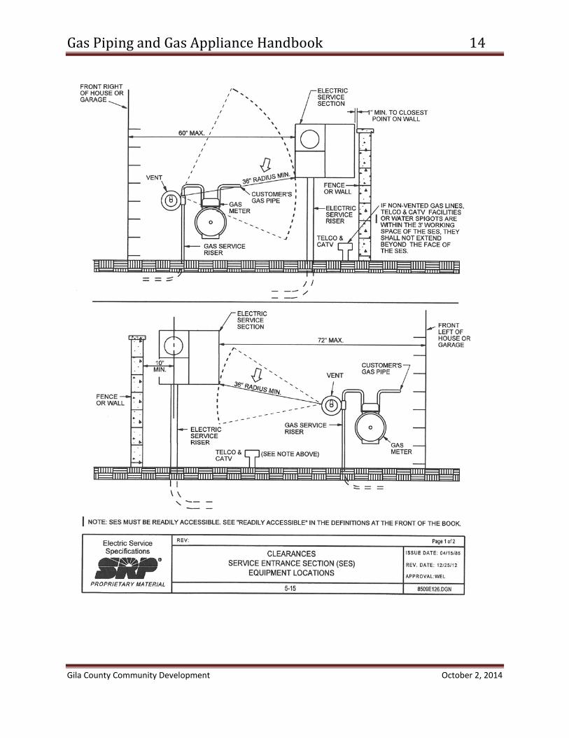
INSTALLATION: (G2415, Gila Co. Amendment) • See Figures on pages 13 and 14 for electrical utility requirements. • Piping shall not be installed in or through a ducted supply, return or exhaust, or
chimney or gas vent. • Pipe, fittings, valves or other materials shall not be used again unless they are free of
foreign materials and have been ascertained to be adequate for the service intended.
• Corrugated stainless steel tubing (CSST) shall be installed per the manufacturer’s listing and installation instructions.
• Piping shall not penetrate building foundation walls at any point below grade. • Piping other than steel must be protected against physical damage. • See specific code sections for piping installation in solid floors and underground
beneath buildings. • Piping installed outdoors above grade shall be elevated a minimum of 3 ½ inches,
securely supported, and protected from physical damage. • Metallic piping and tubing that conveys gas from a propane container shall be
provided with an approved dielectric fitting installed aboveground outdoors. • Metallic pipe or tubing in contact with soil shall be protected in an approved manner
and: o A zinc coating (galvanizing) is not adequate. o Protective coatings and wrapping shall be factory applied except for field
applications shall be permitted for pipe nipples, fittings and where the factory coating or wrapping has been damaged or necessarily removed at joints.
• Metal piping shall be installed a minimum of 12 inches and plastic piping 18 inches below grade.
• Gas outlets that do not connect to appliances shall be capped gas tight. • The unthreaded portion of gas piping outlets shall extend not less than 1 inch
through finished ceilings and walls, and 2 inches through floors, outdoor patios and slabs.
• Gas outlets shall not be located behind doors and be located in the room or space where the appliance is located.
• Plastic pipe shall be installed outdoors and underground only. • A yellow insulated copper tracer wire not less than 18 AWG suitable for direct burial
or other approved conductor shall be installed adjacent to the plastic piping with the tracer wire ends terminating above ground at each end of the plastic piping.
• Before any system piping is put into service or concealed, it shall be tested to ensure that it is gas tight. See TESTING section of this handbook.

Gas Piping and Gas Appliance Handbook 10
Gila County Community Development October 2, 2014
SHUTOFF VALVES
• Shall be of an approved type; constructed of materials compatible with the piping, and shall comply with the standard that is applicable for the pressure and application. (G2420.1.1)
• Valves shall be prohibited in concealed locations and furnace plenums. (G2420.1.2) • Valves shall be located in places as to provide access for operation and shall be
protected from damage. (G24201.3) • Each appliance shall be provided with a shutoff valve which will be:
o Located in the same room as the appliance. o Located within 6 feet of the appliance. o Installed upstream of the union or connector it serves. o Allowed to be installed in an area remote from vented decorative appliances and
room heaters. See code section for additional requirements.
TANKS
• Gas tanks and cylinders shall be permitted and inspected. • Tanks shall be located on the property in accordance with Gila County zoning
requirements. • See LP gas tank installation requirement figures starting on page 11, for tank
location requirements per NFPA 58. • Tanks located in the floodplain must adhere to any requirements stipulated by the
Gila County Floodplain Administrator. • Underground tank installations shall meet zoning setbacks and cannot not be
located where motor vehicle traffic occurs. • Provide impact protection for tanks subject to physical damage from vehicles. • Tanks and cylinders shall be listed and labeled. • Underground gas tanks shall be specifically listed for below grade installation. • Provide Gila County the manufacturer’s specifications that state the tank is
approved for underground installation.
TESTING OF SYSTEMS
• Gas piping is to be inspected prior to being covered or concealed to insure the type, size and installation meet code.

Gas Piping and Gas Appliance Handbook 11
Gila County Community Development October 2, 2014
• The piping must be pressure tested at not less than one and one-half times the proposed maximum working pressure, but not less than 3 psig. 10 lbs. of air will usually meet this requirement.
• The test duration shall not be less than 10 minutes. • The installer is responsible for performing the test and must be witnessed by the
building inspector. • Where new branches are installed to new appliances, only the newly installed
branches shall be required to be pressure tested.
FIGURES

Gas Piping and Gas Appliance Handbook 12
Gila County Community Development October 2, 2014

Gas Piping and Gas Appliance Handbook 13
Gila County Community Development October 2, 2014
Gas Piping and Gas Appliance Handbook 14
Gila County Community Development October 2, 2014