Embed Size (px)
Citation preview

GIBSWAL DX?iAMICS Convair Division Life Sciences
LIFE suppoRT SYS'J!lM FOR SPACE
FLIGHTS OF TlME PERIOD6
Prepared for
HASA/Iangley Research Center Iangley Station
Hampton, Virginia 23365
Prepared by So McCunney/J. Burnett
Approved by
Deputy Program Manager h-ogram Manager
https://ntrs.nasa.gov/search.jsp?R=19660017938 2018-06-24T09:42:15+00:00Z

TABLE OF C 0 " S
4.1.1 Current Configuration
4.1.2 Developmental History
4.1.3 Unit performance
4.1.4 Recommendations
i
L i s t of Illustrations
1. moIxTcTIoN
2. SUMMARY OF LIqusD/GAS SEPARATION - ISS
2.1 Requirements
2.2 Problems Encountered
2.3 Recammendations
3. STATIC sEPmRs
3.1 Cabin Air-Water Separator
3 . 1 . 1 C u r r e n t Configuration
3.1.2 Develo-pental History
3.1.3 Performance
3.1.4 Recamendations
0 2 Reduction Unit Water Separator 3.2
3.2.1 Current Configuration
3.2.2 Develapnental History
3.2.3 Unit Performance
3.2.4 Recanmendations
4. DYNAMIC SEPARATORS
4.1 Water Reclaamtion - A i r Evaporation U n i t , Water Separators
iii
1
1
1
2
2
3
7 J
3
8
11
ll
14
14
14
18
18
la 18
19
19
21
21
4.2 Waste Management and Personal Hygiene, Water Separators
4.2.1 Current Configuration
4.2.2 Developmental History
4,2,3 Wzit Perfonnance
4.2.4 Recamendations
5. m C E -ATION
ii
21
21
24
25
28
28

LIST OF UIUSTRATIONS
1. Current Configuration
2. A i r Deflection
3. Capillary Forces
4. Cabin Air -Wate r Separator Schematic
5 . Chevron Packing
6. TRW punr~ capacity
7.
8.
9.
Modified Gorman Rupp Pump and Control
CO2 Reduction Unit Flow Schematic
CO2 Reduction Unit Water Separator
10. Water Expulsion Tank
11. Centrifugal Water Separator - A i r Turbine Driven
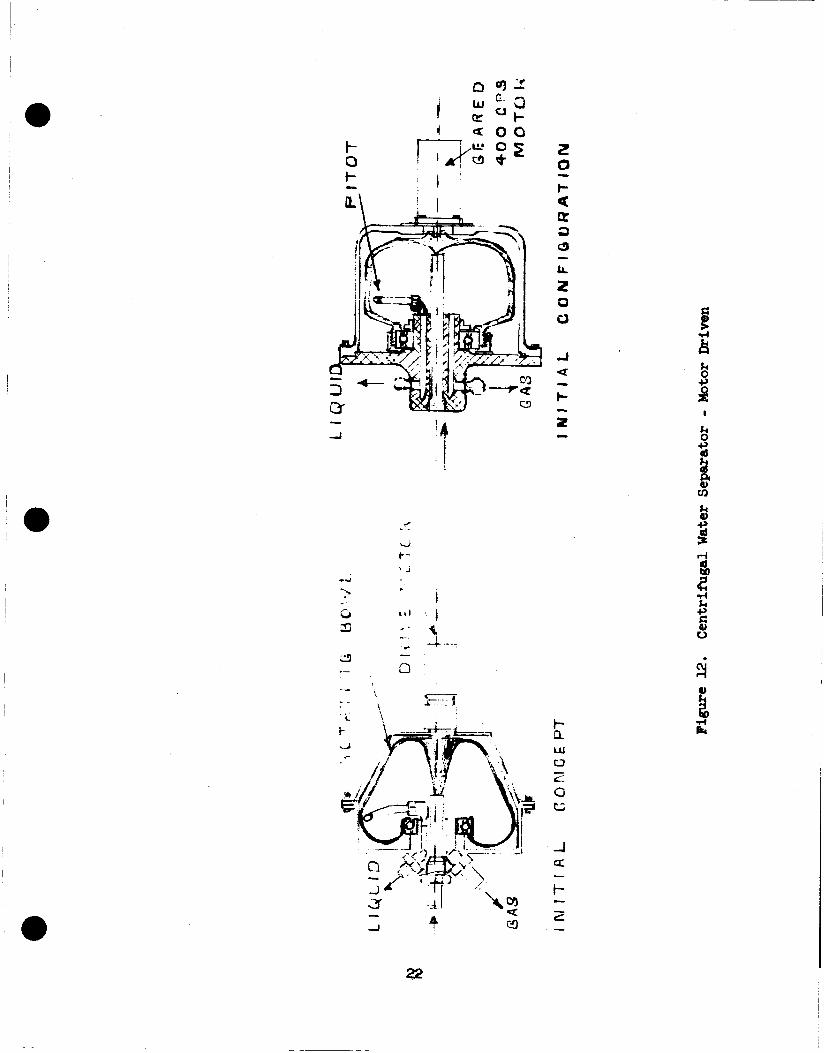
12. Centrifugal Water Separator - Notor Driven I n i t i a l Concept - I n i t i a l Configuration
13. Centrifugal Water Separator - Motor Driven Final Configuration
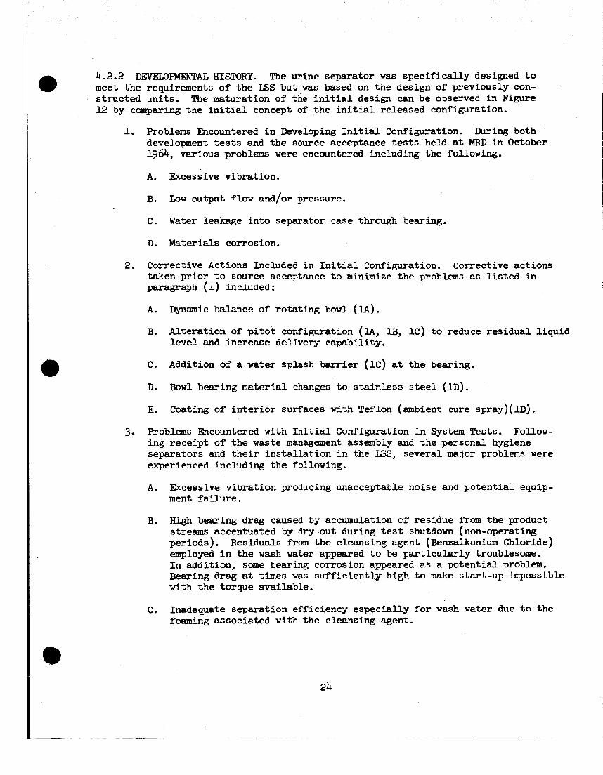
14. Hon-Metallic Bearing - Suggested Configuration
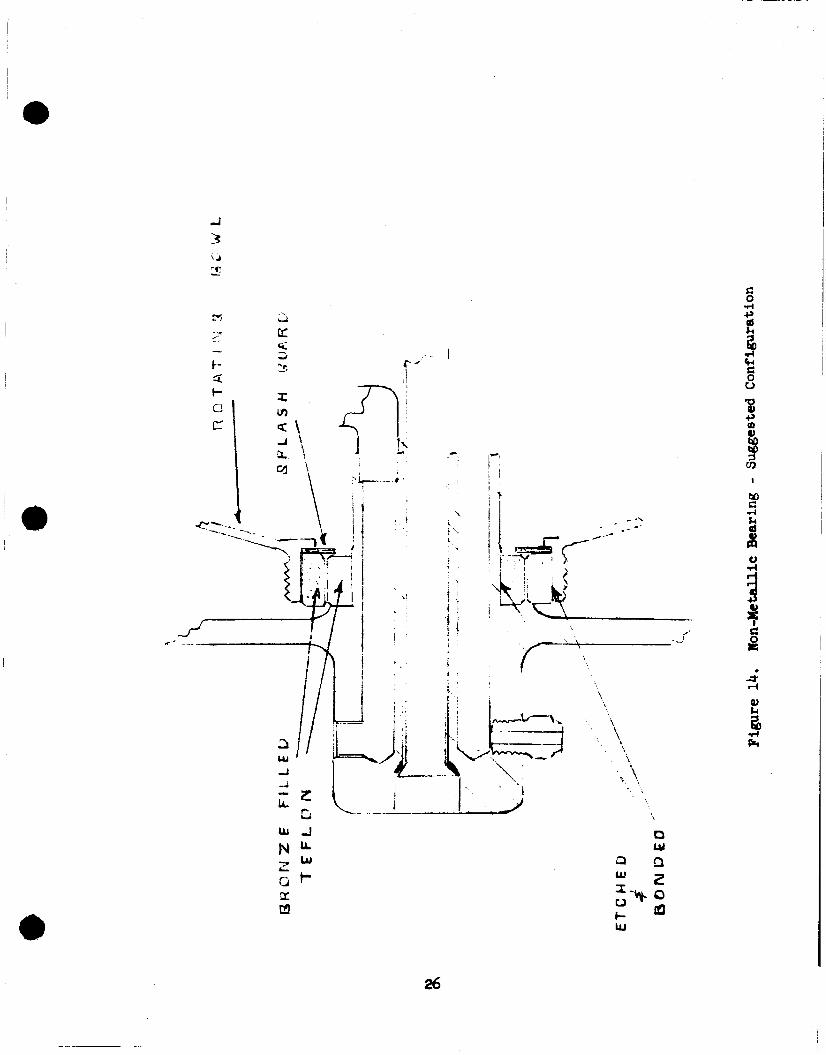
15. Centrifugal Water Separator - Motor Driven Delivery Characterist ics
iii
4
5
6
7
9
10
12
15
16
17
20
22
23
26
27

l/INTRODUCTION
Liquid/gas separation mechanisms fo r manned spacecraft have t r ad i t i ona l ly presented major problems i n ground test and f l i gh t applications. I n select ing the liquid/gas separation mechanisms f o r t he prototype l i fe support system both static and dynamic techniques w e r e included, each t o be produced i n several configurations f o r the various applications. This approach was taken t o assure a broad range of experi- ence frm which sigriif icS,t information could be obtained i n a minimum of program time. The approach has proven to be a v a l i d one.
This report presents a summary of the experiences dealing d i r ec t ly w i t h the several liquid/gas separation mechanisms employed i n applications spec i f ica l ly in- volved w i t h air-water separation. Tne report summarizes requirements, describes types of mechanisms employed, outl ines develapmental problems and solutions attempted, b r i e f ly discusses current performance of the various units, and recom- mends actions fo r continued development as required.
SUMMARY OF LIQUID/GAS SEPARATION - ISS 2.1 REQUIRZXENTS
Requirements f o r liquid/gas separation ex i s t i n a wide var ie ty of functions within the prototype ISS. gravi ty w i t h performance demonstration at one-G. Specific mechanisms a r e required f o r liquid/gas separation i n zero gravity t o complete the following functions.
Each requirement includes operating capabi l i t i es under zero
a 1.
2.
3.
4. --
5 -
6 .
Cabin A i r Humidity Control
C02 Reduction Product Water Removal
Electrolysis Unit Product Gas Removal
Evaporation Water Recovery
Urine Collection
Waste Wash Water Collection
S t a t i c mechanisms which accomplish separation by direct ing entrained l iqu id droplets t o porous plates are employed by the first three. mechanisms which produce a centrifugal force and accomplish
converging, ro ta t ing drum are employed i n t h e last three functions.
Dynamic separation a ra t ion by direct ing
entrained l i q u i d droplets i n to a probe a t the inner surface r f a diverging-
1

Each application has experienced development problems of varying severity. cations have been required f o r each ins t a l l a t ion ranging f'rm v i r t u a l redesign t o simple repair. but, i n varying degree, has added t o an over-all concern regarding the r e l a t ive ly underdeveloped s t a t u s of li quid/gas separation.
Modifi-
Each application has performed adequately i n final system tests
The cabin air-water separator was by far the most troublesome. P la te leakage, although ult imately reduced i n both frequency and magnitude, existed throughout the program. cation, during handling, and i n assembly operations. I n addition, the durabi l i ty of t h e assembly remains i n question with respect t o degradation of porosity caused by corrosion and contamination.
*
The s intered metal porous p la t e s are de l ica te and e a s i l y damaged i n f ab r i -
The evaporation uni t separator w a s :he next most troublesome. Torque limita- t ions of the air turbine drive combined with design and configuration problems associated with the water pickup probe ( p i t o t ) severely limited operation and efficiency. uni t ized (sealed) design of the case.
Correction of these d i f f i c u l t i e s was v i r tua l ly impossible due t o the
The urine and wash water separators experienced excessive vibration, l imited torque and bearing degradation. not considered complete.
Modifications were r e l a t ive ly e f fec t ive but are
The reduction un i t separator has proven r e l a t ive ly sa t i s fac tory primarily due t o its heavy, r i g id construction and i ts inherently simple separation task, aided by a liberal pressure g r a d i e n t and gravity. The only s ignif icant problem involved loss of plate porosity through carbon contamination resu l t ing from upstream component failures.
a 2.3 -TIOI'?S
It i s recommended t h a t a program be undertaken a t t h i s time t o spec i f ica l ly develop new or modified liquid/gas separator configurations f o r t he LSS i n i ts current prototype s ta tus w i t h ?Anther development t o a f l i g h t configuration. sidered tha t t h e experience at t h i s point has been suf f ic ien t ly def in i t ive t o both support the recommendation and t o provide a p rac t i ca l basis f o r rapid and economical development. l eve l w i l l not produce e i the r adequate un i t performance or sa t i s fac tory integrated
- performance.
/ It 1s con-
It has been demonstrated tha t random developments at the component
2

3.1 CABIN AIR-WATW SEPARATOR
The cabin air-water separator controls cabin humidity by removing water droplets from the air stream i n the cabin air duct after they have been condensed and agglo- merated by the system "A" cabin air heat exchanger. transferred t o the CT-2 col lect ion tank of the water magement system by .m elec- t r ical ly-dr iven pump which matches the catch r a t e of the separator, Reference (1). The basic separation function is performed w i t h no moving par t s ( s t a t i c ) , by d i rec t ing entrained water droplets t o porous metal p la tes which provide a liquid/ gas in te r face through capi l lary action permitting water t o flow through t h e p l a t e t o the separator pump. water w i l l flow through the p l a t e s t o the separator pump inlet. excluded.
Condensate is continuously
If a i r pressure forces are iess Clan capi i iary forces, The air w i l l be
Efficiency is measured by the percentage of condensed water which is removed
The basic configuration by the separator, and is d i rec t ly related t o the separator configuration fo r a given w a t e r droplet size, dis t r ibut ion and a i r velocity. used i n the l i f e support system was developed by t h e Electromechanical Division of TRW but w a s mod i f i ed by Convair t o improve performance, reduce air leakage, and provide adequate pumping. crew is 19.6 lb/day, t h e separator specification required e peak water removal capacity of 3.7 lb/hr from a 900 Ib/hr air stream i n a 10 ps ia cabin. able entrained moisture i n the d i s c h a r g e air w a s 0.15 l b /h r , corresponding t o an efficiency of 9%.
Although the anticipated moisture output of a four-man
The allow-
3.1.1 CONFIGURATION. The water separator and header assembly a re modi- f ica t ions of the or ig ina l TRW configuration, consisting of a flanged housing which i s ins ta l led i n the ve r t i ca l section of the cabin air duct downstream of heat ex- changer "A", and an a r ray of porous p l a t e assemblies. The porous p l a t e assemblies are aligned wi th the duct but b a f f l e s axe employed t o def lect the a i r and d i rec t entrained w a t e r droplets t o the plates, where they are "swallowed" by capi l lary act ion, Figures 1, 2, and 3. Each double p l a t e assembly i s made of two porous sheets of sintered nickel which a r e attached t o a supporting frame t o form a water cavity. r a to r housing being solid metal. b o t t m t o common Tygon manifolds which lead t o the pump. pla tes has been reduced from nine t o four t o accommodate the baffles. area w a s reduced from 95 sq.in. t o 38 sq.in. and the air makes a 180° turn a t each of the eight baffles.
End p la t e assemblies have only one porous sheet, the s ide facing the sepa-
The number of double The w a t e r cav i t ies are connected a t t h e top and
N e t flow
The TRW pump failed t o del iver water at the required discharge pressure, was not self-priming and was found t o l o s e prime a t a suction head of 0.3 psig. pump w a s removed frcm the instrument and control panel and replaced w i t h a modif ied Gorman Rupp osc i l la t ing pump, Figure 4. ins ta l led t o remove l iquid carry-over from the sump downstream of the separator, and return it t o the duct upstream of the heat exchanger.
The
An additional pump of t h i s type w a s a l so

a u 4

a
5
f 'i
c
I '
4
6

P 919 8 2
-%I==-
I I I
1 I
T I I I I I ===
I I I I
A m u
1 k 0 c, (d
P,
G d P (d u
I
I
7
3.1.2 DEVEWIpPIwTAL HISTORY. w i t h a scheduled delivery date of 7 August 1964. appeared t o m e e t the specification requirements had been developed and tested a t TRW. because of d i f f i c u l t y with t h e t e s t specimen and t h e T R W test f a c i l i t y . f igurat ion employed s t a in l e s s steel wool packing between the porous p l a t e assem- bl ies , contained i n w i r e mesh. Chevron-shaped grooves i n the end p la tes were intended t o impart a "V" form t o the packing so t h a t water droplets might migrate toward the porous p l a t e s under t h e influence of the dynamic pressure of the air
I n April 1964, TRW contracted t o develop a separator By 6 July a configuration which
Attempts t o rerun these tests for formal acceptance by Convair were abandoned The con-
stream, Figure 5. \
The separator assembly w a s l e f t a t TRW and the t rans i t ion duct and sample porous p l a t e assemblies were shipped t o Convair. assemblies showed severe air leakage a t 1 p s i d i f f e ren t i a l pressure due t o ineffec- t i v e o r damaged solder between p l a t e and frame. Smal l specimens were fabricated f'rom the TRW p la tes t o evaluate both an adhesive bonding, and attachment by welding. A sa t i s fac tory bond w a s obtained w i t h FM lo00 adhesive on a 0.187-inch frame f o r the sealing surface i n l i e u of the 0.09 inch of the TRW design. Porous p l a t e material and the remaining pa r t s were shipped frm T R W 3 December, and new p la t e assemblies w e r e fabricated by Convair using adhesive bonded chem-milled plates.
When tested a t Convair, most of the p l a t e
The bonding technique has proven t o be workable but p l a t e construction is such t h a t cracking and puncture occur ra ther frequently during the bonding process and i n subsequent handling operations. i n t e g r i t y i s the d i f f i c u l t y i n obtaining sa t i s fac tory control and test of p l a t e quali ty. form and continuous p l a t e wetting during operation have r e s u l t e d i n a continuing p l a t e leakage problem throughout t he test program.
Further complicating the problem of p l a t e
These factors coupled with the inherent d i f f i c u l t i e s i n maintaining uni-
Two nev configurations which produced a more posi t ive flow direct ion were fabricated and tested f o r comparison with the or ig ina l separator assembly which employed the open matrix, metalic mesh chevrons t o d i rec t t h e entrained water onto the plates . The first essent ia l ly added a ser ies of sol id p l a t e "V" baffles t o t h e or ig ina l m e t a l mesh chevrons. The second discarded the metal mesh "agglomera- to r" and substi tuted a series of offset, s t r a igh t ( f la t plate) baf f les t o produce an air f l a w labryinth across the separator.
w e r e conducted t o determine i ts pumping character is t ics , Figure 6 . showed that the or ig ina l pump could not meet the desired capacity of 3.7 lb/hr with a suction pressure of 3 ps ig and discharge pressure of 5 psig. The pump WEB not self-priming and would lose prime when air bubbles were introduced t o the inlet. These deficiencies axe d i r ec t ly related t o the very low catch rate of the separator and were inherent t o the pump design, which attempts t o accollllDodate this catch rate.
h e t o the lack of def ini t ive information concerniag the or ig ina l pump, tests These tests
a

a
3
u k E 9

d c

Explanation of the observed characterist ics i s as follows:
1.
2.
3.
4.
Failure t o pump t o design pressure: 5 ps ig reduced the volume per stroke below the 0.9 cc required t o del iver 3.7 l b l h r . and the e f fec t ive stroke m5 zero.
Deformation of the diaphraeprs a t
Deformation at 5.7 psig completely canceled pumping action
Fai lure t o pump against 3.0 psig vacuum: t o zero by the inlet pressure bias, evidence t h a t the bias vorked as intended, but w i t h excessive sens i t iv i ty .
The ef fec t ive stroke was reduced
Fai lure t o self-prime: t o the to'al ~ 4 . - a e of the piq chambers, check ~cl-ve c8~ities &x? e q t y inlet l i nes - a r a t i o of about 13o:l. proportional t o the volume rat io , or about four inches of water f o r full pump stroke. Th i s was the cracking pressure of the check valves so t ha t the pump would not self-prime.
The volume per stroke was extremely mall compared
The pressure change per stroke was
bss of prime due t o air bubbles: Prime i s l o s t i f the t o t a l volume of air bubbles i n the i n l e t l i ne and pump reduces the pressure change per stroke t o cracking pressure of the check valves. vated by the reduction i n effective stroke when the pump is working against a vacuum.
The tendency is aggra-
As a r e s u l t of t h i s investigation the or ig ina l pump was replaced by a Corman Rupp solenoid-driven, osci l la t ing, two-stage, bellows punrp. As shown on Convair Drawing 64-26177, an adjustable controller was ins ta l led i n the separator pump e l e c t r i c a l c i r c u i t t o permit manual adjustment of pump displacement and thus ad- justment of separator p l a t e A P. An addi t ional pump of the same type w a s added t o the c i r c u i t t o recycle the water carry-over collected i n the sump dovnstream of the separator, back t o the i n l e t s ide of the condensing heat exchanger.
3.1.3 PERFORMANCE. of the three separator configurations evaluated i n the test bed during the test program conducted a t Convair, the f i n a l configuration was found t o have 5 6 better efficiency than the or ig ina l configuration when instal led f o r the 10 psia demonstration test of 15 Ju ly 1965, Table 3.1.3. It is noted t h a t a considerable water carry-over was re-evaporated i n the discharge duct during all tests. When an allowance is made fo r this re-evaporation, the apparent efficiency of the in s t a l l a t ion is s igni f icant ly better than the efficiency of the separator alone. The apparent efficiency attained by the s t r a igh t baffle configuration was 95.5$, primarily because the reduced cabin pressure permits a greater absolute humidity in the discharge duct.
3.1.4 -!CION. The s t a t i c porous p la t e cabin air-water separator proved t o be leakage-prone throughout the e n t i r e program. and eas i ly damaged i n fabr icat ion and handling, and the durabi l i ty of the plate- to-frame bond remains a question. I n addition, long-term tes t ing is l i k e l y t o reveal other expected problems such as corrosion and degradation of plate porosity.
.
The sintered m e t a l is de l ica te
These known and suspected shortcomings of t h i s s t a t i c separator j u s t i f y study of other s t a t i c separation techniques i n conjunction with serious consideration of a ro ta t ing dynamic separator fo r cabin a i r systems.
11

i Check Valve i I
- ~~
Ho. 2 Pump and Control no. 3 Pump and Control
’ !
I r-
MExiImlm Parameter
no. 1 Base Armp
Inlet Suction (psig - negative)
Discharge Pressure
Delivery (pph)
(psi8 - pOSitiVe) 1.8
4.75
240.0
%pabillties (1) 1 ~ o m ~ n a l Operatton (2)
2.5 1.5
1.5
2.0 +3 -2
(1) Each value indepaent ly obtained; i .e., for Ho. 1, delivery vas obtained with discharge at 0 psig and inlet at or above 0 psig.
(2) Values are simultaneously obtained.
Figure 7. Modified Gorman Rupp Pump and Control

Table 3.1.3. Cabin A i r - W a t e r Separator Tes t R e s u l t s
Date 5 January 1965 8 February 1965 15 July 1965 Configuration Chevron Packing "V" Baffle Straight Baffle Cabin Pressure, p s i a 14.7 14.7 10.0
I n l e t b tc t : air flow, lb/hr 1630 1192 756
vet ~ C B temperature, OF 60,s a,? 4 .? rel. humidity, $ 54.0 37.4 59.5 abs. humidity, lb / lb dry air 0.00885 0.00755 0.Olog total moisture input, 1blh.r 14.40 9.00 8.25
dry bulb temperature, %' 71.5 77.5 64.3
Heat Exchanger Discharge: dry bulb temperature, 9 42.5 41.3 32.0 w e t bulb temperature, ?F 42.5 41.3 32.0 rel. humidity, $ 100 100 100
water condensed, l b / b 5.05 2.46 4.12
abs. humidity, l b / l b dry air 0.00573 0.00548 0.00545 water vapor output, lb/hr 9.35 6.54 4.13
Separator : water separated, lb/hr 1.28 1.36 1.52
water leakage, lb/hr (estimated) 0.50 0.18 trace water trapped, lb/hr 0.17 0.06 0.07
dry bulb temperature, 9 48 46 44 Discharge met:
Apparent Efficiency,
65.5 85.0 95.5 water separated water removed
,\\
- __-

3.2 C02 REDUCTION UrJIT WATER SEPARANR
The steam formed i n t h e Bosch and Sabatier reactors of the CO2 reduction un i t is l iquefied i n a glycol-cooled condenser and removed from the system through a porous p l a t e water separator. As i n the cabin air-water separator, capi l lary action of the porous plate maintains a gas-water interface w h i c h seals i n the gas against system pressure but permits product water to flow through as it is formed. gases are recycled through the Bosch reactor t o achieve the des i red process rate w i t h a reactor of reasonable size, and if the product water is not removed the react ion would cease. Recovery and storage of product water is essent ia l to the long-term econmy of the cabin atmsphere, oxygen regeneration being acccmtplished by the e lec t ro lys i s of water frcm storage.
System
The separator must accammodate a large range i n gas flow, t h e recycle rate i n
Since t h e nominal water rate is 1.2 cc/min i n Sabatier and 2.4 cc/min in t h e Bosch mode of operation being about 75 times the methane flow from the Sabatier reactor. Bosch, the l iquid water content of the gas is abaut 38 times greater i n Sabatier than i n Bosch.
3.2.1 CUItRWT CONFIGUFMTION. The water separator u t i l i z e s a single sheet of porous sintered nickel, mounted between neoprene gaskets and clamped i n a two-piece sand- wich l i k e housing. When securely bolted together the assembly forms a leak tight, wire-packed gas passage with large intake and discharge manifolds, and a w a t e r cavity served by two smaller manifolds. The water manifolds are used t o f i l l the w a t e r cavity and w e t and s e a l the porous pla te p r io r t o use, as well as t o remove product water. which form on the wire packing are eventually directed t o the porous p la t e by t h e force of gravity.
!&e separator i s instal led horizontally so t h a t the water droplets
Water flaws f r a m the separator, t o an expulsion tank which can hold several
Check valves are ins ta l led i n the water hours' of water production, t he vater and gas chambers of the tank being separated by a f l ex ib l e spring-loaded diaphraea. inlet and delivery l i n e s so that water can be periodically expelled by manual ope- r a t ion of a pneumatic valve which admits pressurized nitrogen t o the gas chamber of the tank. management system . The expelled vater is directed t o collection tank CT-2 of the water
3.2.2 I l E X E I D m HISTORY. The TRW separator t h a t came w i t h the reduction un i t w a s f'unctionally ident ica l t o the current separator and worked properly throughout t he Convair test program u n t i l a high temperature carbon f i l ter fai led, blocking the separator w i t h carbon and making it inoperative. patterned after the original, but w i t h a better bolt c i r c l e and la rger liqluid manifolds .
The replacement separator was
\ The TRW water pump was not self-priming and would lose prime lX,gas bubbles
w e r e introduced t o the pump in le t . Since t h e gas side pressure of t h e w a t e r sepa- r a t o r is always posit ive, the pump w a s replaced w i t h an expulsion tank whqch has the added advantage of r e l i ab le delivery t o any tank pressure that does not exceed the regulated pressure of the nitrogen expulsion gas.
14

4
t- s

€34 L P t W N O VALVE H I 0 2 F
8. cD2 Reduction Unit Flow Schematic I

. 2
ic U
L T O R
Figure 9. Reduction U n i t Water Separator
16

Figure 10. Water Bxpulsion Tank

3.2.3 UNIT PERFORMANCE. reduction unit i n June 1965 as part of the comprehensive redesign accauplished at t h a t time. The un i t was operated i n the Bosch m o d e i n a 10 psia cabin during the demonstration test of 13 Ju ly 1965, and again on 15 July t o demonstrate the Sabatier mode of operation. l ished i n each mode and no d i f f i cu l ty w a s encountered i n start, run, or shutdown. Complete test r e s u l t s a r e documented i n the Final Demonstration Test Report,
The porous p la te water separator w a s ins ta l led i n the
Full process rate and water production vere estab-
64-26228 . Detailed instructions f o r operating the redesigned reduction unit, including
wetting and sealing the water separator, are contained i n the Handbook of Operating InStNCtiOnS, 64-26230 . 3.2.4 RECCMKENM'TIONS. Although trouble-free performance of t h i s porous p la te separator i s expected, programs for advanced studies of liquid/gas separation techniques should include the requirement of t h i s application.
The dynamic separators chosen for the prototype ISS employ a driven rotat ing member t o impart a centrifugal force t o the l iquid pa r t i c l e s contained i n the liquid/gas mixture. The mixture is impinged on the inner surface of the ro ta t ing "bowl" which i n turn drives the l iqu id t o i t s major in te rna l diameter. The liquid, assuming a uniform cross section, impinges on a s t a t i c p i t o t tube which d i rec ts t h e water flow i n t o a collection c i rcu i t . sure rise which can be at ta ined by any given configuration is dependent on such elements as p i t o t design, bowl diameter, ro ta t iona l speed, liquid/bowl interface f r ic t ion , and c i r c u i t resistance. Two configurations are employed, one configura- t i on ins ta l led i n each evaporation unit downstream of the condenser, the other con- f igurat ion i n the w a s t e management system as a urine/air separator and i n the per- sonal hygiene area as a vaste air-water separator on the discharge s ide of the sponge squeezer.
The separation eff ic iency and t h e magnitude of the pres- 0
Problems were experienced u i t h both configurations i n a l l three of the appli- cations. both by excessive bearing drag resul t ing fYan poor lubricat ion and contamination, together with bowl drag and P or water stream slippage. Other problems were associated spec i f ica l ly w i t h the two d i f fe ren t configurations, the differences i n the applications, and t o some extent the nature of the l iquid being processed.
One common problem was insuff ic ient driving torque. This was accentuated
i t o t or ientat ion and configuration problems leading t o excessive
4.1 W A m RGCLAMATION - AIR E V . . T I O N UNIT, W A m SEPARATORS
The separators ins ta l led in the evaporation uni t s are air turbine-driven centrifugal separators, designed and produced by Hamilton Standard Division of U n i t e d A i r c r a F t . The separators w e r e designed f o r a specific spacecraft application and were adapted t o the LSS evaporation uni t a i r cLrcuits. t i on un i t s were developed re uired t h a t the separators del iver essent ia l ly air-free water at the rate of 1.25 lb ? h r t o a system holding tank pressure of 2 psig, and t o do so at both one-C and zero-G.
The specification under which the evapora-
4.1.1 CURREar CONFIGURATION. l ished by rework at HSD inmediately following the source acceptance t e s t s and is shown on €ED - SVSK58050B, "Water Separator, Centrif'ugal," which is reproduced i n a generalized form i n Figure U.
The current configuration of t h e separator was estab- 0
4.1.2 DEVEWpMENTAlr HISTORY. The f l i gh t requirements under which t h e i n i t i a l design of the separator was developed, resulted i n a decision t o produce the uni t i n a unitized (sealed) configuration to meet the ;nfnfii;ilm veight acd develop IVominal water delivery and pressure rise requirements f o r the i n i t i a l design were s l i g h t l y lower than those f o r the ISS evaporation uni ts . been in f luen t i a l i n the evaporation unit application, however, the sealed configu- r a t ion has been by far the dominant l imitation as it has v i r tua l ly eliminated the poss ib i l i t y of corrective and improvement actions during tne program. hring tne source acceptance tests a t HSD i n October 1964, separator stall w a s experienced and a pump was temporarily added which pumped water from the separator case drain and a downstream water t rap in to the external product water storage tank.
demands.
These two factors have
Following the source acceptance t e s t s i n which the or iginal separator problems The new separators were were defined, HSD elected t o fabricate two new separators.
delivered t o Convair i n January 1965. separator No. 1 developed both l o w r ~ p n and surge and an accompanying noise. un i t w a s removed and returned t o HSD for rework. severely limited corrective action. Within this limitation, several f ixes were attempted. Bearings and bearing preload were changed and the m e t a l mesh (droplet agglomeration) removed with l i t t l e or no change i n the drag and noise conditions. Following X-ray, which indicated the poss ib i l i ty of interference i n either o r both t h e bowl t o case seal and the p i t o t assembly, seal clearances were increased. This apparently resulted i n reduced drag and noise. test indicated that i t s performance had been restored t o approximately i t s or iginal value.
During the in i tFa l system tests a t Convair,
Again the "sealed" configuration The
Return of the separator t o system
As subsystem and system test experience increased through functional checkout and performance evaluation, it became apparent tha t separator stall was frequent both during s tar t -up and during test and often was of suf f ic ien t severi ty t o re- quire evaporation un i t shutdown and rather complex corrective measures. experience had demonstrated tha t s ignif icant corrections within the "sealed" sepa- r a to r s were not possible. Therefore, system changes were made t o minimize the probabi l i ty of separator s ta l l and t o make correction of a s ta l l a simple operator task.
Previous
One such change reduced the resistance of the product water c i r cu i t t o t he holding tanks. The other change added a separator purge c i r cu i t which removes excess l iquid from e i the r the case or ro ta t ing bowl and in jec ts the purge in to the air stream at the evaporator inlet . should be required only during start up. t i on t e s t ing where scheduled s tep changes i n a i r f l o w and/or thermal balance can be expected during the course of a single t e s t , separator s t a l l may occur while t he un i t is operating. Extensive tes t ing has shown t h a t the two system changes a re e f fec t ive and except f o r bearing d r a g problems, w i l l produce "acceptable" operation of t he water separation function i f not of t h e separators themselves. The separator purge requirement undoubtedly w i l l e x i s t i n one form o r another with a l l dynamic separators i n both one-g and zero-g environments. configuration and gravi ta t ional affects w i l l alter but not eliminate the purge re- quirement and the type of mechanisms employed.
During normal operation the purge c i r c u i t However, during development and evalua-
The differences i n

! : ! I
w I
I- CE
c?)
I 3

4.1.3 IMtT P2Z?FORWI!lCE. out altering the product w a t e r c i rcui ts . ps ig at the holding tank while unit No. 2 c8z1 a t t a i n s l i g h t l y over 2 psig. Charac- t e r i s t i c speeds fo r un i t Xo. 1 a t a sea l e v e l ambient fa l l i n the range of 2100-2200 rpol and l5OO-l8OO rpp at an ambient of 10 ps i a w h i l e un i t Ho. 2 aperates i n a range of 2200-2400 rpm at sea level and 1~-2200 x p a t 10 psia. mass flow i n t h e evaporation air c i r cu i t w i l l influence separator ~psn, as will changes in the residual liquid i n the sepe3.stor case 8nd water "level" i n the rota- t i n g bowl. I n normal operation these changes are not suf f ic ien t t o cause trouble. How-, deviations fran the charac te r i s t ic speed ranges resu l t ing fram s tep changes i n operating conditions are rapid in build up, e i the r going t o 3000-4500 rpm indi- cating an abnormally lav o r no process rate or t o a stalled or near s t a l l e d condition, ilidie$iting excessive water "ievels" fn the sepra%or.
Beither unit can m e e t the pressure rise requirements with- Unit Ho. 1 can a t t a i n approximately 0.7
Any fac tor affect ing
Following extended shutdown, an addi t ional problem has been experienced. The un i t s have been d i f f i c u l t t o start and operate a t a lower rpn than normal. t i o n of the separators has revealed excessive bearing drag caused by a gum-like contaminate i n the bearing. relieved the problem.
gwaclna-
Clean q or replacement of t he bearings has temporarily
4.1.4 RBXWENMTIOISS. Convair and Hamilton Standard t o analyze and correct the problems being exprienced. Because of the "sealed" configuration adopted fo r the i n i t i a l design and sub- sequently carried over t o the current configuration, no s ignif icant progress has been made. I n addition, it is not l ike ly that corrective progress can be made with the current uni ts . Recamendations thus involve an investigation i n t o a new design which w i l l permit disassembly, produce an optimized p i t o t design, tolerage the con- taminants inherent i n the process stream, provide adepte torque and torque charac- t e r i s t i c s t o handle the load and i ts variations, and include self-purging crrpabil- i t ies as requi red .
Repeated and exhaustive attempts have been made by both
The separators employed f o r air-urine separation i n w a s t e management and for waste wash water i n personal hygiene are ident ical motor-driven centrifugal separators designed and produced by MRD of General American Transportation Corporation. separator design was spec i f ica l ly developed t o pe r fow the liquid/- separation function required by the u r ina l assembly of the w a s t e management. t i o n under which the design was developed required that the separator deliver e s sen t i a l ly air-free urine et the rate of 2.40 lb/hr, at an ou t l e t pressure of 5 psig. I n addition, it is r e q u i r e d t a do so w h i l e operating with a l iquid con- t e n t as high as two pounds and t o do so at both one-g and zero-g. ur ine mixture is drawn through the urinal and in to the separator bowl by venting t h e bowl t o the low pressure of the waste management assembly blower in l e t .
4.2.1 CUflRElyT OOHFIGURATION. The i n i t i a l configuration of the separator, Shawn i n Figure 12, has been s ignif icant ly modified as shown by Figure 13. present i n the f i n a l configuration include:
The
The specifica-
The inlet air-
The changes
1. Addition of a housing mounted dr ive support bearing.
* - 0 2. Replacement of t he drive motor with a motor of higher torque.
3. Ins t a l l a t ion of an improved p i to t .
21
I
22

I
I I I
4.2.2 a E ” T A L HISTORY. The urine separator was specif ical ly designed t o m e e t the requirements of the ISS but was based on the design of previously con- s t ructed units. The maturation of the i n i t i a l design can be observed i n Figure 12 by comparing the i n i t i a l concept of the i n i t i a l released configuration.
1. Problems Encountered i n Developing I n i t i a l Configuration. During both development tests and the source acceptance tests held at MRD i n October 1964, various problems were encuuntered including the following.
A. Excessive vibration.
B.
C. Water leakage i n t o separator case through bearing.
LOW output flow and/or pressure.
~ D. Materials corrosion.
2. Corrective Actions Included i n I n i t i a l Configuration. Corrective actions , taken pr ior t o source acceptance t o minimize the problems as l i s t e d i n I
paragraph (1) included:
A.
B.
Dynamic balance of rotat ing bowl (U).
Alteration of pitot configuration (IA, lB, 1C) t o reduce residual l iqu id l e v e l and increase delivery capability.
C.
D.
Addition of a water splash barrier (1C) at the bearing.
Bowl bearing m a t e r i a l changes t o stainless steel (1D).
E. Coating of i n t e r io r surfaces with Teflon (ambient cure spray)(lD).
3. Problems Encountered with I n i t i a l Configuration i n System Tests. Follow- ing receipt of t h e w a s t e management assembly and the personal hygiene separators and t h e i r ins ta l la t ion i n the ISS, several major problems w e r e experienced including t h e following.
A. Zxcessive vibration producing unacceptable noise and poten t ia l equip- ment fa i lure .
B. H i g h bearing drag caused by accumulation of residue f r o m the product streams accentuated by dry out during tes t shutdown (non-operating periods). Residuals from the cleansing agent (Benzalkonium Chloride) employed i n the wash water appeared t o be par t icu lar ly troublesome. I n addition, same bearing corrosion appeared as a poten t ia l problem. Bearing drag at times was su f f i c i en t ly high t o make s tar t -up impossible w i t h the torque available.
C. Inadequate separation efficiency especially f o r wash water due t o the foaming associated w i t h the cleansing agent.
24

4. Corrective Actions Applied to the Initial Configuration. Corrective action taken to minimize the problems during the system test program and prior to the final test as listed in paragraph (3) included:
A. Removal of the torque limited, flange-mounted, 400 cps, miniature geared motor and installation of a base-mounted, 60 cps, commercial direct drive motor of higher torque capability (3B).
B. Elimination of bowl drive axis run-out (3).
C. Installation of a second bowl support bearing mounted on the separator housing (3).
D. Installation of an improved pitot (3, 3C).
E. Replacement of stainless steel components wherever possible with alumi- num components to reduce corrosion accelerated by the materials incompatibility.
F. Investigation of (not installed) replacement of the high drag metallic ball bearing employed as the bawl main support bearing with a low drag, non-metal, corrosion and contaminate resistant sleeve bearing. Various materials, materials combinations, and bearing configurations were investigated. The selected candidate was bronze-filled Teflon for both elements of the bearing (journal and sleeve). The molded raw stock is available as MB (7*) ea rn Raybestos-Manhattan, Inc., Aero- space Division, 14-00 E. Orangethorpe Avenue, Fullerton, California. The material is compounded as WP No. 147 by Liquid Nitrogen Products, Santa Ana, California. Figure 14 illustrates the approach selected. It is believed that this type of bearing would also eliminate much of the noise associated with the large metallic ball bearing. schedules did not permit application of this essential step.
Program
4.2.3 U" PERFORMANCE. Both separators in their final configuration are capable of delivering a sufficient quantity of liquid, adequately free of air, and at suf- ficient pressure to meet the anticipated demands of extended man tests. However, neither unit is capable of meeting the specified peak flow rate in its current (final) configuration. Figure 1 5 shows the delivery characteristics of the two units in their final configuration and of the urine separator in its initial con- figuration. being employed, accentuated by inadequate lubrication, together with its intolerance to contamination will continue to limit the performance of the units. has been reduced to a point where it would appear that the potential for vibration induced material failures has been significantly reduced if not eliminated. Noise problems associated with the installation structure still persists although of a greatly reduced level. Much of the start and stop vibration associated with ex- cessive residual liquid levels has been eliminated but vibration still exists to the extent that vibration damping mounts are required to keep noise at an acceptable level.
The inherently high torque requirement for the large ball bearing
Vibration
25
'\ \
i
- z L s
26

4.2.4 REC-TIONS. non-metallic sleeve type bearing be examined. One separator could be immediately modified and subjected t o a n inclusive test program. The re su l t s of this program could form the s t a r t i ng point f o r the new separator design program recommended i n Section 4.1.
It is recommended tha t the application of t h e two-element,
Reports
G4-25201
64-26228
64 -02024
64-02003
6 4 - 02018
64-02006
64-02005
Drawings
64-26100
64 -26182
64-26167
64-26177
64-26161
TRW mg. 818478
TRW Dwg. 81835
64-26169
ASD-SVSK-58050
64-26166
MRD-l252-1500A
64-26163
Systm qp~f~&-G7i~ _ _ Ufe p----+ C..rC U p p U A Y UJUUm
Final Demonstration and Test Report
Cabin A i r - W a t e r Separator -- Specification
C02 Reduction U n i t -- Specification
Waste Heat Air Evaporation Water Recovery -- Specification
Waste Management System -- Specification
Water Electrolysis Unit -- Specification
Schunatic of Integrated Life Support System
Subsystem Product Flaw Diagram
Cabin A i r - 5 0 Separator Unit Systan D i a g r a m
Water Separator Cabin Air Elec t r ica l D i a g r a m
C02 Reduction U n i t System Diagram
Water Separator and Header Assembly
Cabin Air-Water Separator Schematic
A i r Gvaporation Water Recovery System D i a g r a m
Centrifugal Separator
Waste Management System D i a g r a m
Separator Assembly
H20 Electrolysis Unit System Diagram
28