Embed Size (px)
Citation preview

Giant Monopole Resonances in
Unstable Nuclei Presented by W. F. McGrew, Juniata College Advisor: Dr. D. H. Youngblood Collaborators: J. T. Button and Dr. Y.-W. Lui Texas A&M University

Isoscalar Giant Monopole Resonance • Giant resonances – collective excitation of nucleus due to
near-exhaustion of Energy-Weighted Sum Rule
• ISGMR is a “breathing mode,” a rapid expansion and shrinking of the nucleus
http://cyclotron.tamu.edu/pics/structure_01.bmp
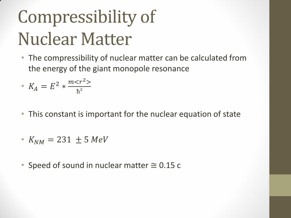
Compressibility of Nuclear Matter • The compressibility of nuclear matter can be calculated from
the energy of the giant monopole resonance
• 𝐾𝐴 = 𝐸2 ∗𝑚<𝑟2>
ħ2
• This constant is important for the nuclear equation of state
• 𝐾𝑁𝑀 = 231 ± 5 𝑀𝑒𝑉
• Speed of sound in nuclear matter ≅ 0.15 c

Typical Method
• Collide a beam of alpha particles with a target to excite it into ISGMR
• Measure energy and angular distribution of outgoing alpha particles
• The angular distribution tells us which are from the ISGMR, and the energy of those alpha’s gives the energy of the ISGMR

Unstable Nuclei
• The problem: a target can not be made of unstable nuclei
• The solution: switch the role of beam and target
• However, alpha particles are helium, which is a gas at room temperature
• Instead, the target will be made of 6Li, a solid
• Experiments with ISGMR using 6Li give similar results to those involving alpha particles

Experimental Setup
Image courtesy of J. T. Button

My Role
• Determine the relative gain of the individual strips in the scintillator detector
• Account for attenuation in the scintillator strips
• Design a Faraday cup to catch the beam after exiting the MDM spectrometer but before entering the wire detector
• If the beam was not stopped, it would damage the detector

Scintillator Detector
• Used to determine energy and scattering angle of small decay particles like alphas and protons
• Consists of 13 vertical strips directly in front of 12 horizontal strips
• Five vertically-oriented blocks catch all particles that pass through the first two layers
• Examining the vertical and horizontal layers in coincidence map out 152 “pixels” which give the scattering angle
• The beam and residual decay particles pass through an opening in the center of the detector

• Schematic diagram of detector
• Scattering angle indicated for each pixel
• Strip is attached to fiber-optic cable, which carries photons to photo-multiplier tubes
• One concern is attenuation

Test runs
• Test runs were performed using both protons scattering off of a 12C target and a beta source
• The beta tests were ultimately disregarded for analysis due to proximity to threshold

Analysis
• The data were analyzed on a pixel-by-pixel basis
• The elastic peak was isolated and its mean value was determined
Dealing with attenuation
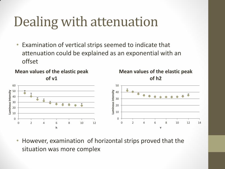
• Examination of vertical strips seemed to indicate that attenuation could be explained as an exponential with an offset
• However, examination of horizontal strips proved that the situation was more complex
0
10
20
30
40
50
60
0 2 4 6 8 10 12
Lum
ino
us
Inte
nsi
ty
h
Mean values of the elastic peak of v1
0
10
20
30
40
50
0 2 4 6 8 10 12 14
Lum
ino
us
inte
nsi
ty
v
Mean values of the elastic peak of h2

Angular effects
0
0.5
1
1.5
0 2 4 6 8 10 12
1/co
sθ
h
Angular effects of apparent length for v1
0
0.5
1
1.5
0 2 4 6 8 10 12 14
1/co
sθ
v
Angular effects of apparent length for h2
0
10
20
30
40
50
60
0 2 4 6 8 10 12
Lum
ino
us
Inte
nsi
ty
h
Mean values of the elastic peak of v1
0
10
20
30
40
50
0 2 4 6 8 10 12 14
Lum
ino
us
inte
nsi
ty
v
Mean values of the elastic peak of h2

Energy and scattering angle
• The kinetic energy of the particles is greater near the center (h9, in this instance)
• The particles deposit more energy at extreme angles
43.5
44
44.5
45
45.5
46
46.5
47
47.5
48
0 2 4 6 8 10 12
Lum
ino
us
inte
nsi
ty
h
Mean values of the elastic peak of e2

Symmetric points
• By finding the ratio of points symmetric about the center, attenuation could be determined
• Attenuation has a linear relationship with distance over the area of interest
• Oddly, max attenuation varied between 7% and 30% among the various strips
y = -0.0136x + 1.0122
0.75
0.8
0.85
0.9
0.95
1
1.05
1.1
0 2 4 6 8 10 12
Rat
io b
etw
een
sym
met
ric
po
ints
Distance between symmetric points
h2 Attenuation Data
0
10
20
30
40
50
0 2 4 6 8 10 12 14
Lum
ino
us
inte
nsi
ty
v
Mean values of the elastic peak of h2

Determining relative gain
• By comparing pixels with equal scattering angles, the relative gain could be calculated
Image courtesy of J. T. Button
v1 0.40
v2 0.70
v3 0.62
v4 0.65
v5 1.00
v6 0.94
v7 1.11
v8 1.18
v9 0.80
v10 0.63
v11 0.74
v12 0.48
h1 0.57
h2 0.69
h3 1.23
h4 0.94
h5 1.15
h6 2.01
h7 1.85
h8 1.00
h9 1.25
h10 1.05

Principles of a Faraday cup
• A beam of ions impinges upon a metal surface
• The charge hits the surface and flows to ground, resulting in a measurable current
Ions A

My Design
• Designed using AutoCAD 2002
• Used SRIM (Stopping Range of Ions in Matter) program
• One thin layer of aluminum to stop the beam
• A much thicker layer of tantalum to stop alpha particles produced by the beam

Entire assembly


Additional specifications
• The mounting of the cup will be made of plastic to electrically isolate it
• Electrical connection will be made using a brush sliding over a PC-board
• The screw will be powered with a motor positioned outside of the box
• A position sensor will be used inside the box

The Next Step
• The Faraday cup must be constructed
• The cyclotron must be conditioned for the higher energies that will be used in this experiment
• The experimental phase should begin next Fall, with a beam of stable 28Si, to assure that the experiment is providing the expected results
• Finally, the experiment can be performed on unstable nuclei

Acknowledgements
Dr. Youngblood, my mentor, for sharing his years of experience and providing invaluable guidance
Jonathan Button and Dr. Lui, for their support and patience
Sherry Yennello, Lauren Heilborn, and Leslie Speikes for coordinating the REU program
The National Science Foundation and the Department of Energy for providing the funds to make this experience possible
My fellow REU students for providing an excellent environment in and out of work


![[0.94]Task Scheduling to Constrain Peak Current](https://img.dokumen.tips/doc/110x75/626e279cc1717a0a2577d3e5/094task-scheduling-to-constrain-peak-current-.jpg)