Embed Size (px)
Citation preview

190-02246-11 January 2020 Revision 1
GI 275 Part 23 AML STCMaintenance ManualContains Instructions for Continued Airworthiness
for STC SA02658SE
Aircraft make, model, registration number, and serial number, along with the applicable STC configuration information, must be completed in Appendix A and
saved with aircraft permanent records.
190-02246-11 GI 275 Part 23 AML STC Maintenance ManualRev. 1 Page i
© 2020Garmin International, Inc., or its subsidiaries
All Rights Reserved
Except as expressly provided herein, no part of this manual may be reproduced, copied, transmitted, disseminated, downloaded, or stored in any storage medium, for any purpose without the express prior written consent of Garmin. Garmin hereby grants permission to download a single copy of this manual and of any revision to this manual onto a hard drive or other electronic storage medium to be viewed and to print one copy of this manual or of any revision hereto, provided that such electronic or printed copy of this manual or revision must contain the complete text of this copyright notice and provided further that any unauthorized commercial distribution of this manual or any revision hereto is strictly prohibited.
SkyWatch® and Stormscope® are registered trademarks of L-3 Communications. Ryan®, TCAD®, and Avidyne® are registered trademarks of Avidyne Corporation. AC-U-KWIK® is a registered trademark of Penton Business Media Inc. Bendix/King® and Honeywell® are registered trademarks of Honeywell International, Inc.
© 2020 SiriusXM Radio Inc. Sirius, XM and all related marks and logos are trademarks of SiriusXM Radio Inc. All other marks and logos are property of their respective owners. All rights reserved.
Garmin®, FliteCharts®, and SafeTaxi® are registered trademarks of Garmin International or its subsidiaries. Connext™, GDU™, GTN™, SVT™, and Telligence™ are trademarks of Garmin International or its subsidiaries. These trademarks may not be used without the express permission of Garmin.
The Bluetooth® word mark and logos are registered trademarks owned by Bluetooth SIG, Inc. and any use of such marks by Garmin is under license. Other trademarks and trade names are those of their respective owners.
ChartView™ is a trademark of Jeppesen, Inc.
Windows® is a registered trademark of Microsoft Corporation in the United States and other countries.
© 2020 SD® is a registered trademark of SD-3C, LLC. All rights reserved.
Iridium® is a registered trademark of Iridium Communications, Inc. All rights reserved.
The term Wi-Fi® is a registered trademark of the Wi-Fi Alliance®.
All other product or company names mentioned in this manual are trade names, trademarks, or registered trademarks of their respective owners.
For aviation product support, visit flyGarmin.com.
For information regarding the Aviation Limited Warranty, refer to Gamin's website.
190-02246-11 GI 275 Part 23 AML STC Maintenance ManualRev. 1 Page ii
INFORMATION SUBJECT TO EXPORT CONTROL LAWSThis document may contain information that is subject to the Export Administration Regulations (EAR) issued by the United States Department of Commerce (15 CFR, Chapter VII, Subchapter C) and may not be exported, released, or disclosed to foreign nationals inside or outside of the United States without first obtaining an export license.
The information in this document is subject to change without notice. For updates and supplemental information regarding the operation of Garmin products, visit flyGarmin.com.
Software License NotificationAES Encryption
The product may include AES file encryption software, © 2002 DR. Brian Gladman, subject to the following license:
The free distribution and use of this software in both source and binary form is allowed (with or without changes) provided:
• Distributions of this source code include the above copyright notice, this list of conditions, and the following disclaimer.
• Distribution in binary form include the above copyright notice, this list of conditions, and the following disclaimer in the documentation and/or other associated materials.
• The copyright holder’s name is not used to endorse products built using this software without specific written permission.
Alternatively, provided this notice is retained in full, this product may be distributed under the terms of the GNU General Public License (GPL) in which case the provisions of the GPL apply instead of those given above.
Disclaimer
The AES file encryption software is provided “as is” with no explicit or implied warranties in respect of its properties, including, but not limited to, correctness and/or fitness for purpose.

190-02246-11 GI 275 Part 23 AML STC Maintenance ManualRev. 1 Page iii
SOFTWARE LICENSE AGREEMENT FOR GARMIN AVIATION PRODUCTSThe software embedded in your Garmin product (the “Licensed Software”) is owned by Garmin International, Inc. (“Garmin” or “us”). The Licensed Software is protected under copyright laws and international copyright treaties. The Licensed Software is provided under this Software License Agreement (hereinafter the “Agreement”) and is subject to the following terms and conditions which are agreed to by End User (“Licensee”, “you” or “your”), on the one hand, and Garmin and its licensors and affiliated companies of Garmin and its licensors, on the other hand. The Licensed Software is licensed, not sold, to you. Garmin and Licensee may be referred to individually as a “Party” or jointly as the “Parties.”
IMPORTANT: CAREFULLY READ THIS ENTIRE AGREEMENT BEFORE USING THIS PRODUCT. INSTALLING, COPYING, OR OTHERWISE USING THIS PRODUCT INDICATES YOUR ACKNOWLEDGMENT THAT YOU HAVE READ THIS AGREEMENT AND AGREE TO ITS TERMS AND CONDITIONS. IF YOU DO NOT AGREE TO THESE TERMS AND CONDITIONS, YOU MAY NOT USE THIS PRODUCT.
1. Definitions. The following capitalized terms shall have the meanings set forth below:
a. “Device” means any Garmin device that is delivered by or on behalf of Garmin to Licensee onto which the Licensed Software is installed.
b. “Documentation” means Gamin's then-current instructional, technical or functional documentation relating to the Devices or Licensed Software which is delivered or made available by Garmin in connection with this Agreement.
c. “Licensed Software” means the software in binary executable form that is embedded in the Devices and/or made available for use on the Devices via a software loader card.
d. “Permitted Purpose” means operating and using the Device on which the Licensed Software is installed for the Device's intended use.
2. License.
a. License Grant. Subject to the terms and conditions of this Agreement and Licensee's compliance with the terms and conditions of this Agreement, Garmin hereby grants to Licensee a limited, royalty-free, non-exclusive, non-sublicenseable, non-transferable and revocable right and license to use and perform the Licensed Software as installed on the Devices and the Documentation solely for the Permitted Purpose and only during the term of this Agreement, provided that the Licensed Software may only be used by Licensee on Devices on which the Licensed Software has been installed or otherwise made available by Garmin.
b. Reservation of Rights. Garmin retains exclusive ownership of all right, title and interest in and to the Licensed Software and Documentation. All of Gamin's rights in and to the Licensed Software and Documentation not expressly licensed to Licensee under Section 2.1 are expressly reserved for Garmin. Nothing contained in this Agreement shall be construed as conferring by implication, acquiescence, or estoppel any license or other right upon Licensee. Without limiting the foregoing, the Parties acknowledge and agree that this Agreement grants Licensee a license of the Licensed Software under the terms of Section 2.1, and shall not in any manner be construed as a sale of the Licensed Software or any rights in the Licensed Software.
3. Restrictions; Protection and Third Party Devices.
a. Prohibited Uses. Licensee shall not, shall not attempt to and shall not permit any third party to: (a) sublicense, lease, loan, sell, resell, market, transfer, rent, disclose, demonstrate, or distribute the Licensed Software or Documentation to any third party; (b) uninstall the Licensed Software from the Device on which it was originally installed; (c) make any use of or perform any acts with respect to

190-02246-11 GI 275 Part 23 AML STC Maintenance ManualRev. 1 Page iv
the Licensed Software or Documentation other than as expressly permitted in accordance with the terms of this Agreement; (d) use the Licensed Software or Documentation in any manner that violates any applicable law; (e) reproduce or copy the Licensed Software; (f) modify, adapt, alter, translate, port, create derivative works of, reverse engineer, decompile or disassemble the Licensed Software or Documentation or otherwise derive the source code or other proprietary information or trade secrets from the Licensed Software; (g) remove, alter, or obscure any proprietary notices from the Licensed Software or Documentation; (h) use the Licensed Software or Documentation to provide services to third parties (such as business process outsourcing, service bureau applications or third party training); (i) use the Licensed Software on any equipment, hardware or device other than a Device; or (j) export, re-export or otherwise distribute, directly or indirectly, the Licensed Software or Documentation to a jurisdiction or country to which the export, re-export or distribution of such Licensed Software or Documentation is prohibited by applicable law.
b. Protection of Software and Documentation. Licensee shall use its best efforts to protect the Licensed Software and Documentation from unauthorized access, distribution, modification, display, reproduction, disclosure or use with at least the same degree of care as Licensee normally uses in protecting its own software and documentation of a similar nature from unauthorized access, distribution, modification, display, reproduction, disclosure or use. Licensee shall limit access to the Licensed Software and Documentation to only those employees of Licensee who require access to the Licensed Software or Documentation for the Permitted Purpose and who have been made aware of the restrictions set forth in this Agreement. Licensee shall take prompt and appropriate action to prevent unauthorized use or disclosure of the Licensed Software and Documentation.
4. Term and Termination.
a. Term. The term of this Agreement shall commence on the Effective Date, and shall continue in perpetuity thereafter, unless terminated earlier as provided in this Section 4.
b. Termination by Garmin. Garmin may immediately terminate this Agreement upon written notice to Licensee if Licensee commits a material breach of this Agreement or breaches a material term of this Agreement.
c. Effect of Termination. Upon any termination of this Agreement for any Party: (a) Licensee shall immediately cease all use of the Licensed Software and Documentation; (b) all rights and licenses granted to Licensee to the Licensed Software and Documentation and Gamin's related obligations shall immediately terminate; and (c) Sections 4.3, 5 and 6 shall survive.
5. Disclaimer; Limitations of Liability; Indemnity.
a. DISCLAIMER. TO THE MAXIMUM EXTENT PERMITTED BY APPLICABLE LAW, THE LICENSED SOFTWARE AND DOCUMENTATION (INCLUDING ANY RESULTS TO BE OBTAINED FROM ANY USE OF THE LICENSED SOFTWARE AND DOCUMENTATION) ARE PROVIDED “AS IS” AND “AS AVAILABLE” WITH NO WARRANTIES, GUARANTEES OR REPRESENTATIONS AND NEITHER GARMIN NOR ITS AFFILIATES MAKE ANY REPRESENTATION, WARRANTY OR GUARANTEE, STATUTORY OR OTHERWISE, UNDER LAW OR FROM THE COURSE OF DEALING OR USAGE OF TRADE, EXPRESS OR IMPLIED, INCLUDING ANY WARRANTIES OF MERCHANTABILITY, FITNESS FOR A PARTICULAR PURPOSE, NON-INTERFERENCE, NON-INFRINGEMENT, TITLE, OR SIMILAR, UNDER THE LAWS OF ANY JURISDICTION. GARMIN DOES NOT WARRANT THAT THE LICENSED SOFTWARE OR DOCUMENTATION WILL MEET LICENSEE'S REQUIREMENTS OR THAT OPERATION OF THE SOFTWARE WILL BE UNINTERRUPTED OR ERROR FREE. LICENSEE ASSUMES THE ENTIRE RISK AS TO THE QUALITY AND PERFORMANCE OF THE LICENSED SOFTWARE AND DOCUMENTATION. THE LICENSED SOFTWARE IS NOT INTENDED FOR USE IN ANY NUCLEAR, MEDICAL, OR OTHER INHERENTLY
190-02246-11 GI 275 Part 23 AML STC Maintenance ManualRev. 1 Page v
DANGEROUS APPLICATIONS, AND GARMIN DISCLAIMS ALL LIABILITY FOR ANY DAMAGE OR LOSS CAUSED BY SUCH USE OF THE LICENSED SOFTWARE.
b. EXCLUSION OF DAMAGES; LIMITATION OF LIABILITY. NOTWITHSTANDING ANYTHING TO THE CONTRARY HEREIN, TO THE MAXIMUM EXTENT PERMITTED BY APPLICABLE LAW, UNDER NO CIRCUMSTANCES AND REGARDLESS OF THE NATURE OF ANY CLAIM SHALL GARMIN BE LIABLE TO LICENSEE FOR AN AMOUNT IN EXCESS OF USD $100, OR BE LIABLE IN ANY AMOUNT FOR ANY SPECIAL, INCIDENTAL, CONSEQUENTIAL, PUNITIVE OR INDIRECT DAMAGES, LOSS OF GOODWILL OR PROFITS, LIQUIDATED DAMAGES, DATA LOSS, COMPUTER FAILURE OR MALFUNCTION, ATTORNEYS' FEES, COURT COSTS, INTEREST OR EXEMPLARY OR PUNITIVE DAMAGES, ARISING OUT OF OR IN CONNECTION WITH THE USE OR PERFORMANCE OR NON-PERFORMANCE OF THE LICENSED SOFTWARE OR DOCUMENTATION, EVEN IF GARMIN HAS BEEN ADVISED OF THE POSSIBILITY OF SUCH LOSS OR DAMAGES.
c. Indemnity. Licensee shall indemnify, defend and hold Garmin and its affiliates harmless against any and all losses, claims, actions, causes of action, liabilities, demands, fines, judgments, damages and expenses suffered or incurred by Garmin or its affiliated companies in connection with: (a) any use or misuse of the Licensed Software or Documentation by Licensee or any third party in Licensee's reasonable control; or (b) Licensee's breach of this Agreement.
6. General.
a. No Devices or Services. Licensee acknowledges and agrees that nothing in this Agreement shall be construed as requiring Garmin to: (a) provide or supply the Devices or any other devices or hardware to Licensee; (b) grant any licenses to any software other than the Licensed Software; or (c) provide any services, such as support, maintenance, installation or professional services for the Licensed Software.
b. Non-Exclusive. Each Party's rights and obligations under this Agreement are non-exclusive. Garmin is not precluded from marketing, licensing, providing, selling or distributing the Licensed Software or Documentation, or any other products, software, documentation or services, either directly or through any third party.
c. Assignment. Licensee may not assign this Agreement or any of its rights, interests or obligations hereunder without the prior written consent of Garmin. Any purported assignment in violation of this Section 6.3 shall be null and void. Subject to the foregoing, this Agreement shall be binding upon and shall inure to the benefit of the Parties and their respective successors and permitted assigns and transferees.
d. Feedback and Data. Licensee may from time to time provide feedback, comments, suggestions, questions, ideas, or other information to Garmin concerning the Licensed Software or Documentation or Gamin's products, services, technology, techniques, processes or materials (“Feedback”). Garmin may in connection with any of its products or services freely use, copy, disclose, license, distribute and otherwise exploit such Feedback in any manner without any obligation, payment, royalty or restriction whether based on intellectual property rights or otherwise.
e. Governing Law. The validity, interpretation and enforcement of this Agreement will be governed by the substantive laws, but not the choice of law rules, of the state of Kansas. This Agreement shall not be governed by the 1980 UN Convention on Contracts for the International Sale of Goods.
f. Legal Compliance. You represent and warrant that (i) you are not located in a country that is subject to a U.S. Government embargo, or has been designated by the U.S. Government as a “terrorist supporting” country, and (ii) you are not listed on any U.S. Government list of prohibited or restricted parties.

190-02246-11 GI 275 Part 23 AML STC Maintenance ManualRev. 1 Page vi
g. Injunctive Relief. The Parties acknowledge and agree that irreparable damage would occur if any provision of this Agreement was not performed in accordance with its specific terms or was otherwise breached and as such, the Parties will be entitled to an injunction or injunctions to prevent breaches of this Agreement and to enforce specifically the performance of the terms and provisions of this Agreement without proof of actual damages, this being in addition to any other remedy to which any Party is entitled at law or in equity.
h. Amendments and Waivers. This Agreement may be amended and any provision of this Agreement may be waived, provided that any such amendment or waiver will become and remain binding upon a Party only if such amendment or waiver is set forth in a writing by such Party. No course of dealing between or among any persons having any interest in this Agreement will be deemed effective to modify, amend or discharge any part of this Agreement or any rights or obligations of any Party under or by reason of this Agreement. No delay or failure in exercising any right, power or remedy hereunder will affect or operate as a waiver thereof; nor will any single or partial exercise thereof or any abandonment or discontinuance of steps to enforce such a right, power or remedy preclude any further exercise thereof or of any other right, power or remedy. The rights and remedies hereunder are cumulative and not exclusive of any rights or remedies that any Party would otherwise have.
i. Severability. The provisions of this Agreement will be severable in the event that for any reason whatsoever any of the provisions hereof are invalid, void or otherwise unenforceable, any such invalid, void or otherwise unenforceable provisions will be replaced by other provisions which are as similar as possible in terms to such invalid, void or otherwise unenforceable provisions but are valid and enforceable and the remaining provisions will remain valid and enforceable to the fullest extent permitted by applicable law, in each case so as to best preserve the intention of the Parties with respect to the benefits and obligations of this Agreement.
j. No Third-Party Beneficiaries. This Agreement is solely for the benefit of the Parties and does not confer on third parties any remedy, claim, reimbursement, claim of action or other right in addition to those existing without reference to this Agreement.
k. Entire Agreement. This Agreement shall constitute the entire agreement between Garmin and you with respect to the subject matter hereof and will supersede all prior negotiations, agreements and understandings of Garmin and you of any nature, whether oral or written, with respect to such subject matter.
l. Interpretation. In this Agreement: (a) headings are for convenience only and do not affect the interpretation of this Agreement; (b) the singular includes the plural and vice versa; (c) the words 'such as', 'including', 'particularly' and similar expressions are not used as, nor are intended to be, interpreted as words of limitation; (d) a reference to a person includes a natural person, partnership, joint venture, government agency, association, corporation or other body corporate; a thing includes a part of that thing; and a party includes its successors and permitted assigns; and (e) no rule of construction applies to the disadvantage of a Party because that Party was responsible for the preparation of this Agreement. Any translation of this Agreement from English is provided as a convenience only. If this Agreement is translated into a language other than English and there is a conflict of terms between the English version and the other language version, the English version will control.
190-02246-11 GI 275 Part 23 AML STC Maintenance ManualRev. 1 Page vii
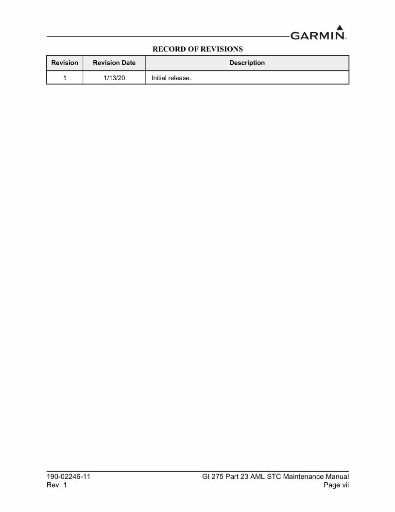
RECORD OF REVISIONS
Revision Revision Date Description
1 1/13/20 Initial release.
190-02246-11 GI 275 Part 23 AML STC Maintenance ManualRev. 1 Page viii
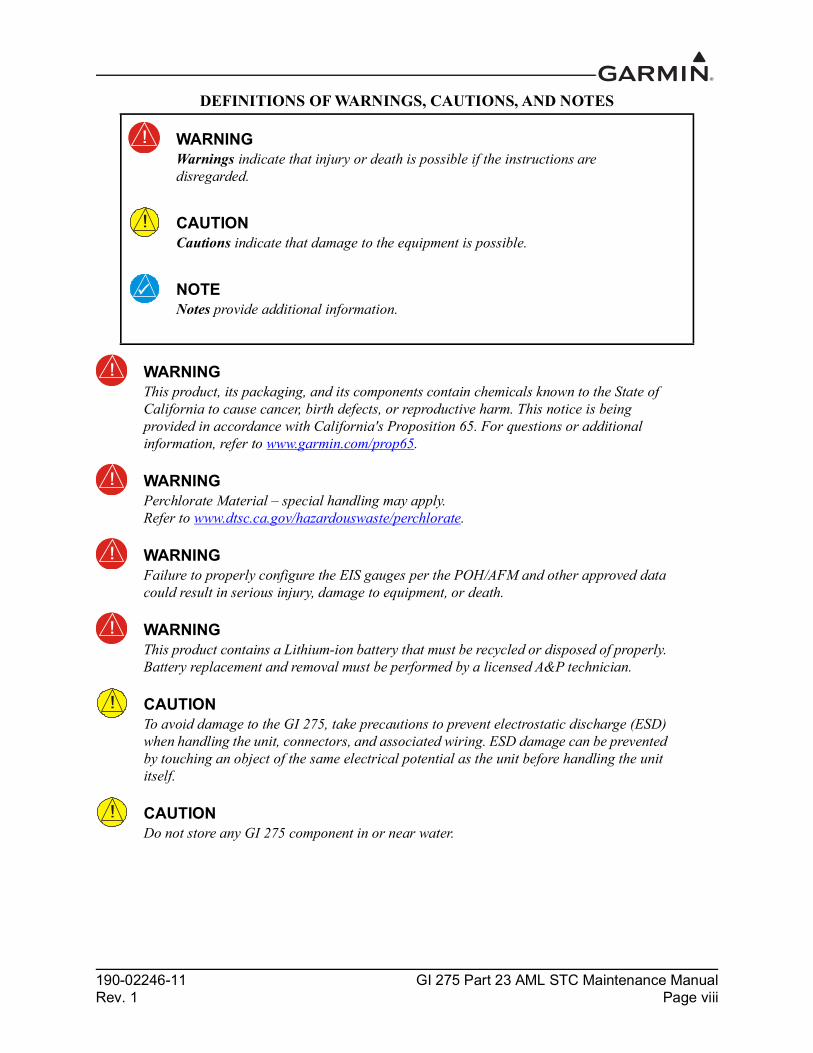
DEFINITIONS OF WARNINGS, CAUTIONS, AND NOTES
WARNINGThis product, its packaging, and its components contain chemicals known to the State of California to cause cancer, birth defects, or reproductive harm. This notice is being provided in accordance with California's Proposition 65. For questions or additional information, refer to www.garmin.com/prop65.
WARNINGPerchlorate Material – special handling may apply. Refer to www.dtsc.ca.gov/hazardouswaste/perchlorate.
WARNINGFailure to properly configure the EIS gauges per the POH/AFM and other approved data could result in serious injury, damage to equipment, or death.
WARNINGThis product contains a Lithium-ion battery that must be recycled or disposed of properly. Battery replacement and removal must be performed by a licensed A&P technician.
CAUTIONTo avoid damage to the GI 275, take precautions to prevent electrostatic discharge (ESD) when handling the unit, connectors, and associated wiring. ESD damage can be prevented by touching an object of the same electrical potential as the unit before handling the unit itself.
CAUTIONDo not store any GI 275 component in or near water.
WARNINGWarnings indicate that injury or death is possible if the instructions are disregarded.
CAUTIONCautions indicate that damage to the equipment is possible.
NOTENotes provide additional information.

190-02246-11 GI 275 Part 23 AML STC Maintenance ManualRev. 1 Page ix
TABLE OF CONTENTS1 INTRODUCTION............................................................................................................................. 1-1
1.1 Purpose .................................................................................................................................1-21.2 Scope .....................................................................................................................................1-21.3 Organization .........................................................................................................................1-21.4 Applicability .........................................................................................................................1-21.5 Publications ...........................................................................................................................1-31.6 Revision and Distribution .....................................................................................................1-31.7 Terminology and Acronyms .................................................................................................1-3
2 SYSTEM DESCRIPTION................................................................................................................ 2-12.1 System Overview ..................................................................................................................2-22.2 Normal Mode Operation .......................................................................................................2-52.3 Configuration Mode Operation .............................................................................................2-62.4 LRU Description, Control, and Operation ............................................................................2-8
3 INSTRUCTIONS FOR CONTINUED AIRWORTHINESS........................................................ 3-13.1 Airworthiness Limitations ....................................................................................................3-23.2 Servicing Information ...........................................................................................................3-33.3 Maintenance Intervals ...........................................................................................................3-43.4 Visual Inspection ..................................................................................................................3-63.5 Electrical Bonding Maintenance Check ...............................................................................3-63.6 Overhaul Period ....................................................................................................................3-73.7 Special Inspection Requirements ..........................................................................................3-73.8 Application of Protective Treatments ...................................................................................3-73.9 Data Relative to Structural Fasteners ...................................................................................3-73.10 Additional Instructions .........................................................................................................3-7
4 TROUBLESHOOTING ................................................................................................................... 4-14.1 General System Troubleshooting .........................................................................................4-24.2 Connector Information ..........................................................................................................4-34.3 Troubleshooting Flow Charts .............................................................................................4-17
5 EQUIPMENT MAINTENANCE AND CHECKOUT PROCEDURES...................................... 5-15.1 GI 275 ...................................................................................................................................5-35.2 EIS Annunciator ...................................................................................................................5-65.3 GEA 24 .................................................................................................................................5-85.4 GEA 110 .............................................................................................................................5-105.5 Backup Battery ...................................................................................................................5-135.6 GSB 15 ................................................................................................................................5-145.7 GMU 11 ..............................................................................................................................5-185.8 GMU 44B ...........................................................................................................................5-205.9 GTP 59 ................................................................................................................................5-225.10 VFR GPS Antenna ..............................................................................................................5-245.11 EIS Sensors .........................................................................................................................5-265.12 Calibration ..........................................................................................................................5-345.13 Uploading Software ............................................................................................................5-365.14 System Checks ....................................................................................................................5-37
APPENDIX A INSTALLATION-SPECIFIC INFORMATION ...................................................... A-1A.1 General Information .............................................................................................................A-1A.2 LRU Information .................................................................................................................A-2
190-02246-11 GI 275 Part 23 AML STC Maintenance ManualRev. 1 Page x
A.3 Equipment Location .............................................................................................................A-3A.4 Wire Routing - Single Engine ..............................................................................................A-4A.5 Wire Routing - Twin Engine ...............................................................................................A-5A.6 Saved Configuration File .....................................................................................................A-6A.7 Print Configuration Log .......................................................................................................A-6
190-02246-11 GI 275 Part 23 AML STC Maintenance ManualRev. 1 Page xi
LIST OF FIGURESFigure 2-1 GI 275 Normal Mode.......................................................................................................... 2-5Figure 2-2 Entering Configuration Mode on the GI 275...................................................................... 2-6Figure 2-3 GI 275 Display.................................................................................................................... 2-8Figure 2-4 VFR GPS Antenna.............................................................................................................. 2-8Figure 2-5 GMU 11 Magnetometer...................................................................................................... 2-9Figure 2-6 GMU 44B Magnetometer ................................................................................................... 2-9Figure 2-7 GTP 59 Outside Air Temperature Probe ............................................................................ 2-9Figure 2-8 Backup Battery ................................................................................................................. 2-10Figure 2-9 GSB 15 Charging Hub...................................................................................................... 2-10Figure 2-10 GEA 24 Engine Adapter ................................................................................................... 2-11Figure 2-11 GEA 110 Engine Adapter ................................................................................................. 2-11Figure 2-12 Engine Annunciator (Single) ............................................................................................ 2-12Figure 2-13 Engine Annunciator (Separate)......................................................................................... 2-12Figure 2-14 Carburetor Temperature Probe ......................................................................................... 2-12Figure 2-15 Oil Temperature Probe ..................................................................................................... 2-12Figure 2-16 Fuel Flow Sensor FT-60 (Left) and FT-90 (Right) .......................................................... 2-13Figure 2-17 Brass Pressure Sensor ....................................................................................................... 2-13Figure 2-18 Stainless Steel Pressure Sensor......................................................................................... 2-13Figure 4-1 GI 275 Connectors.............................................................................................................. 4-3Figure 4-2 GI 275 J2751 Connector (Looking at Connector) .............................................................. 4-4Figure 4-3 GI 275 J2752 Connector (Looking at Connector) .............................................................. 4-5Figure 4-4 GEA 24 Connectors............................................................................................................ 4-7Figure 4-5 GEA 24 J241/P241 Connector (Looking at the Connector) ............................................... 4-8Figure 4-6 GEA J242/P242 Connector (Looking at the Connector) .................................................... 4-8Figure 4-7 GEA 24 J243/P243 Connector (Looking at Connector)..................................................... 4-9Figure 4-8 GEA 24 J244/P244 Connector (Looking at the Connector) ............................................. 4-10Figure 4-9 GEA 110 Connectors........................................................................................................ 4-11Figure 4-10 GEA 110 J1101/P1101 Connector (Looking at Connector)............................................. 4-11Figure 4-11 GEA 110 J1102/P1102 Connector Looking at Unit ......................................................... 4-12Figure 4-12 J442/P442 Connector........................................................................................................ 4-14Figure 4-13 GMU 11 Connector .......................................................................................................... 4-15Figure 4-14 GSB 15 Connectors .......................................................................................................... 4-16Figure 4-15 GI 275 Alert Message Troubleshooting ........................................................................... 4-18Figure 4-16 Battery Alert Message Troubleshooting........................................................................... 4-20Figure 4-17 AHRS Alert Message Troubleshooting ............................................................................ 4-24Figure 4-18 ADC Alert Message Troubleshooting .............................................................................. 4-25Figure 4-19 Terrain/TAWS Alert Message Troubleshooting .............................................................. 4-26Figure 4-20 Traffic Alert Message Troubleshooting............................................................................ 4-27Figure 4-21 Audio and Weather Alert Message Troubleshooting ....................................................... 4-29Figure 4-22 NAV Alert Message Troubleshooting .............................................................................. 4-30Figure 4-23 Autopilot Alert Message Troubleshooting ....................................................................... 4-31Figure 4-24 Miscellaneous GI 275 Alert Messages ............................................................................. 4-32Figure 4-25 External LRU Alert Message Troubleshooting ................................................................ 4-33Figure 5-1 GI 275 Installation .............................................................................................................. 5-3Figure 5-2 Configuration Module Installation ..................................................................................... 5-4Figure 5-3 EIS Caution and Warning Annunciator Installation........................................................... 5-6Figure 5-4 Separate EIS Annunciator Installation................................................................................ 5-7Figure 5-5 Example GEA 24 Installation............................................................................................. 5-8

190-02246-11 GI 275 Part 23 AML STC Maintenance ManualRev. 1 Page xii
Figure 5-6 GEA 110 Installation (Mounted Directly to Airframe Example)..................................... 5-10Figure 5-7 GEA 110 Installation (Mounted on a Tray Example) ...................................................... 5-11Figure 5-8 GSB 15 Cutout Installation............................................................................................... 5-14Figure 5-9 GSB 15 Installation with Mounting Kit (2.25-Inch Cutout)............................................. 5-15Figure 5-10 GSB 15 Installation with Mounting Kit (3.125-Inch Cutout)........................................... 5-16Figure 5-11 Example GMU 11 Installation.......................................................................................... 5-18Figure 5-12 GMU 44B Installation ...................................................................................................... 5-20Figure 5-13 GTP 59 Installation (Aircraft with Metallic Skin Example) ............................................ 5-22Figure 5-14 Backup GPS Antenna Installation (Non-removable Installation Example) ..................... 5-24Figure 5-15 Backup GPS Antenna Installation (Removable Installation Example) ............................ 5-25Figure 5-16 Carburetor Temperature Sensor Installation Example ..................................................... 5-27Figure 5-17 Oil Temperature Sensor Installation Example.................................................................. 5-28Figure 5-18 Brass Sensor Installation (Coupling Mount Example) ..................................................... 5-30Figure 5-19 Stainless Steel Sensor Installation (Housing Mount Example) ........................................ 5-31Figure 5-20 Fuel Flow Transducer Installation .................................................................................... 5-33

190-02246-11 GI 275 Part 23 AML STC Maintenance ManualRev. 1 Page xiii
LIST OF TABLESTable 1-1 Reference Documentation ....................................................................................................1-3Table 2-1 AML STC Installed Sensors ................................................................................................2-3Table 2-2 GI 275 LRU Electrical Load ................................................................................................2-4Table 3-1 Periodic Maintenance ...........................................................................................................3-4Table 3-2 Electrical Bonding Maintenance Requirements ...................................................................3-6Table 4-1 GI 275 Failures .....................................................................................................................4-2Table 4-2 J2751/P2751 Connector .......................................................................................................4-4Table 4-3 J2752/P2752 Connector .......................................................................................................4-5Table 4-4 J241/P241 Connector ...........................................................................................................4-8Table 4-5 J242/P242 Connector ...........................................................................................................4-8Table 4-6 J243/P243 Connector ...........................................................................................................4-9Table 4-7 J244/P244 Connector .........................................................................................................4-10Table 4-8 J1101/P1101 Connector .....................................................................................................4-11Table 4-9 J1102/P1102 Connector ....................................................................................................4-12Table 4-10 J442/P442 Connector .........................................................................................................4-14Table 4-11 J111/P111 Connector .........................................................................................................4-15Table 4-12 GTP 59 3-Conductor Shielded Cable .................................................................................4-16Table 4-13 J201/P201 & J202/P202 .....................................................................................................4-16Table 5-1 Pressure Sensor Equipment List ........................................................................................5-29Table 5-2 LRU Status Indicators ........................................................................................................5-37Table 5-3 Airspeed Test Points ..........................................................................................................5-39Table 5-4 Advanced Airframe Specific Configuration Data – Arc Ranges .......................................5-40Table 5-5 Advanced Airframe Specific Configuration Data – Markings ..........................................5-41

190-02246-11 GI 275 Part 23 AML STC Maintenance ManualRev. 1 Page 1-1
1 INTRODUCTION
1.1 Purpose..............................................................................................................................................1-21.2 Scope.................................................................................................................................................1-21.3 Organization......................................................................................................................................1-21.4 Applicability .....................................................................................................................................1-21.5 Publications.......................................................................................................................................1-31.6 Revision and Distribution .................................................................................................................1-31.7 Terminology and Acronyms .............................................................................................................1-3
1.7.1 Terminology ...............................................................................................................................1-31.7.2 Acronyms ...................................................................................................................................1-4
190-02246-11 GI 275 Part 23 AML STC Maintenance ManualRev. 1 Page 1-2
1.1 PurposeThe purpose of this document is to provide Instructions for Continued Airworthiness (ICA) and maintenance information for Garmin GI 275 system as installed under STC SA02658SE. This document also satisfies the requirement for continued airworthiness as required by 14 CFR 23.1529 and Part 23 Appendix G.
1.2 ScopeThis document provides maintenance instructions and identifies the Instructions for Continued Airworthiness for the installation and maintenance of the Garmin GI 275 system as installed under the AML STC.
1.3 OrganizationThe following outline briefly describes the organization of this manual:
Section 2.1: System OverviewProvides a description of the GI 275 system equipment installed by this STC.
Section 2.2: LRU Description, Control, and OperationProvides basic control and operation information specifically tailored to maintenance practices.
Section 3: Instructions for Continued AirworthinessProvides Instructions for Continued Airworthiness of the GI 275 system LRUs.
Section 4: TroubleshootingProvides troubleshooting information, including connector information, pinouts, and flowcharts to aid in diagnosing and resolving problems with GI 275 system equipment.
Section 5: Equipment Maintenance and Checkout ProceduresProvides instructions for the removal and replacement of GI 275 system LRUs, including system checkout procedures.
Appendix A: Installation-Specific InformationProvides a template to record aircraft-specific installation and configuration data for the GI 275 system.
1.4 ApplicabilityThis document applies to all aircraft with the GI 275 system installed in accordance with AML STC SA02658SE. Modification of an aircraft by this STC obligates the aircraft operator to include the maintenance information provided by this document in the operator’s Aircraft Maintenance Manual and the operator’s Aircraft Scheduled Maintenance Program.
190-02246-11 GI 275 Part 23 AML STC Maintenance ManualRev. 1 Page 1-3
1.5 PublicationsIn addition to this manual, the following documents are recommended for performing maintenance on the GI 275 system. It is the responsibility of the owner/operator to ensure the latest applicable versions of these documents are used during operation, servicing, or maintenance of the GI 275 system.
1.6 Revision and DistributionThis document is required for maintaining the continued airworthiness of the aircraft. Garmin dealers may obtain the latest revision of this document at the Garmin Dealer Resource Center website. Dealers are notified of manual revision changes via Garmin Service Bulletins posted to the Dealer Resource Center. Owners and operators may obtain the latest revision of this document at flyGarmin.com or by contacting a Garmin dealer. Garmin contact information is available at flyGarmin.com.
1.7 Terminology and Acronyms1.7.1 TerminologyExcept where specifically noted, references made to “GI 275” will apply to all variants of the GI 275 (i.e., GI 275 Base, GI 275 ADAHRS, and GI 275 ADAHRS+AP).
Except where specifically noted, references made to the “GI 275 system” will apply to an installed system with one or more GI 275 displays and all LRUs interfaced to the GI 275(s).
Throughout this document, references will be made to metallic aircraft. For the purposes of this manual, metallic aircraft will be those with an aluminum skin. Non-metallic aircraft refers to aircraft with an airframe constructed from wood or composite, including exterior skin, or aircraft with metal tubular truss airframe and fabric or composite exterior skin.
Unless otherwise stated, all units of measure are US standard units.
Throughout this manual references will be made to aircraft class. With regards to usage in this manual, the classes are defined as follows:
• Class I: Single reciprocating engine airplane with GTOW of 6,000 lbs or less• Class II: Multi reciprocating engine or turbine engine airplane with GTOW of 6,000 lbs or less• Class III: Airplane with GTOW of more than 6,000 lbs• Class IV: Commuter category aircraft
Refer to AC 23.1309-1E for more information on airplane classes.
Table 1-1 Reference DocumentationDocument Garmin P/N
GI 275 Part 23 AML STC Equipment List 005-01208-42
GI 275 Part 23 AML STC Airplane Flight Manual Supplement 190-02246-12
GI 275 Part 23 AML STC Installation Manual 190-02246-10
GI 275 STC EIS & MFD Installation Manual 190-02246-14

190-02246-11 GI 275 Part 23 AML STC Maintenance ManualRev. 1 Page 1-4
1.7.2 AcronymsThe following terminology is used within this document:
AC Alternating Current IAS Indicated Air SpeedADAHRS Air Data Attitude Heading Reference
SystemICA Instructions for Continued Airworthiness
ADC Air Data Computer LOC LocalizerADI Attitude Direction Indicator LRU Line Replaceable UnitADS-B Automatic Dependent Surveillance
BroadcastMFD Multi-Function Display
AFMS Aircraft Flight Manual Supplement OAT Outside Air TemperatureAHRS Altitude and Heading Reference System ODA Organization Designation AuthorizationAML Approved Model List POH Pilot’s Operating HandbookA/P Autopilot PPS Pulse Per SecondASI Airspeed Indicator RPM Revolutions Per MinuteBIT Built-In Test SBAS Satellite Based Augmentation SystemCFR Code of Federal Regulations SD Secure DigitalCHT Cylinder Head Temperature SDI Source/Destination IdentifiersDC Direct Current STC Supplemental Type CertificateEGT Exhaust Gas Temperature TAS Traffic Advisory SystemEIS Engine Indicating System TAWS Terrain Awareness and Warning SystemFAA Federal Aviation Administration SSM Sign/Status MatrixFD Flight Director TCAS Traffic Collision Avoidance SystemFIS-B Flight Information Services Broadcast TCAD Traffic Collision Avoidance DeviceGDC Garmin Data Computer TIS Traffic Information ServiceGDU Garmin Display Unit TSO Technical Standard OrderGEA Garmin Engine Adapter UAT Universal Access TransceiverGMU Garmin Magnetometer Unit UTC Coordinated Universal TimeGPS Global Positioning System VHF Very High FrequencyGRS Garmin Reference System VOR VHF Omni-Directional RangeGTP Garmin Temperature Probe WAAS Wide Area Augmentation SystemHSI Horizontal Situation Indicator WXR Weather Radar
190-02246-11 GI 275 Part 23 AML STC Maintenance ManualRev. 1 Page 2-1
2 SYSTEM DESCRIPTION
2.1 System Overview..............................................................................................................................2-22.1.1 Primary ADI Functionality.........................................................................................................2-22.1.2 HSI Functionality .......................................................................................................................2-22.1.3 MFD/Standby ADI Functionality...............................................................................................2-22.1.4 HSI/Standby ADI Functionality.................................................................................................2-22.1.5 MFD Functionality .....................................................................................................................2-32.1.6 EIS Functionality........................................................................................................................2-32.1.7 Electrical Load Information .......................................................................................................2-4
2.2 Normal Mode Operation ...................................................................................................................2-52.3 Configuration Mode Operation.........................................................................................................2-6
2.3.1 Entering Configuration Mode ....................................................................................................2-62.3.2 Wireless Connectivity ................................................................................................................2-62.3.3 Import Configuration..................................................................................................................2-62.3.4 Export Configuration..................................................................................................................2-7
2.4 LRU Description, Control, and Operation........................................................................................2-82.4.1 GI 275 Display ...........................................................................................................................2-82.4.2 VFR GPS Antenna .....................................................................................................................2-82.4.3 Integrated ADAHRS ..................................................................................................................2-82.4.4 GMU 11 Magnetometer .............................................................................................................2-92.4.5 GMU 44B Magnetometer...........................................................................................................2-92.4.6 GTP 59 OAT Probe....................................................................................................................2-92.4.7 Backup Battery .........................................................................................................................2-102.4.8 GSB 15 .....................................................................................................................................2-102.4.9 EIS Components.......................................................................................................................2-11
190-02246-11 GI 275 Part 23 AML STC Maintenance ManualRev. 1 Page 2-2
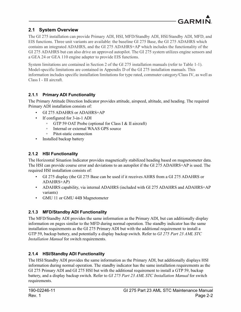
2.1 System OverviewThe GI 275 installation can provide Primary ADI, HSI, MFD/Standby ADI, HSI/Standby ADI, MFD, and EIS functions. Three unit variants are available: the baseline GI 275 Base, the GI 275 ADAHRS which contains an integrated ADAHRS, and the GI 275 ADAHRS+AP which includes the functionality of the GI 275 ADAHRS but can also drive an approved autopilot. The GI 275 system utilizes engine sensors and a GEA 24 or GEA 110 engine adapter to provide EIS functions.
System limitations are contained in Section 2 of the GI 275 installation manuals (refer to Table 1-1). Model-specific limitations are contained in Appendix D of the GI 275 installation manuals. This information includes specific installation limitations for type rated, commuter category/Class IV, as well as Class I - III aircraft.
2.1.1 Primary ADI FunctionalityThe Primary Attitude Direction Indicator provides attitude, airspeed, altitude, and heading. The required Primary ADI installation consists of:
• GI 275 ADAHRS or ADAHRS+AP• If configured for 3-in-1 ADI
GTP 59 OAT Probe (optional for Class I & II aircraft) Internal or external WAAS GPS source Pitot-static connection
• Installed backup battery
2.1.2 HSI FunctionalityThe Horizontal Situation Indicator provides magnetically stabilized heading based on magnetometer data. The HSI can provide course error and deviations to an autopilot if the GI 275 ADAHRS+AP is used. The required HSI installation consists of:
• GI 275 display (the GI 275 Base can be used if it receives AHRS from a GI 275 ADAHRS or ADAHRS+AP)
• ADAHRS capability, via internal ADAHRS (included with GI 275 ADAHRS and ADAHRS+AP variants)
• GMU 11 or GMU 44B Magnetometer
2.1.3 MFD/Standby ADI FunctionalityThe MFD/Standby ADI provides the same information as the Primary ADI, but can additionally display information on pages similar to the MFD during normal operation. The standby indicator has the same installation requirements as the GI 275 Primary ADI but with the additional requirement to install a GTP 59, backup battery, and potentially a display backup switch. Refer to GI 275 Part 23 AML STC Installation Manual for switch requirements.
2.1.4 HSI/Standby ADI FunctionalityThe HSI/Standby ADI provides the same information as the Primary ADI, but additionally displays HSI information during normal operation. The standby indicator has the same installation requirements as the GI 275 Primary ADI and GI 275 HSI but with the additional requirement to install a GTP 59, backup battery, and a display backup switch. Refer to GI 275 Part 23 AML STC Installation Manual for switch requirements.

190-02246-11 GI 275 Part 23 AML STC Maintenance ManualRev. 1 Page 2-3
2.1.5 MFD FunctionalityThe Multi-Function Display provides, at a minimum, a moving map display. The display can optionally provide traffic, terrain, and weather functions depending on installed equipment. The required MFD system installation consists of:
• GI 275 display
2.1.6 EIS FunctionalityThe Engine Indicating System is an optional feature for single- and twin-engine reciprocating engine equipped aircraft listed on the STC AML. The EIS will display 4 and 6 cylinder engine data and select airframe parameters. The EIS can display engine and airframe operating parameters on the GI 275. Configurable EIS gauges include optional gauges and those required by the aircraft POH and manufacturer.
This manual only provides information for the EIS sensors installed per the GI 275 AML STC. Table 2-1 lists the sensors that are maintained in this manual. Refer to the applicable maintenance data and/or TSO manual for other sensors that are interfaced to the EIS.
Table 2-1 AML STC Installed SensorsFunction Manufacturer P/N Garmin P/N
Oil PressGarmin 150 PSIG pressure, (Brass) 011-04202-30
Kulite APT-20GX-1000-150G (Stainless) 494-30032-00
Oil Temp UMA T3B3-2.5G 494-70009-00
Manifold PressGarmin 30 PSIA Press, (Brass) 011-04202-00
Kulite APT-20GX-1000-25A (Stainless) 494-30030-00
Fuel Press
Garmin 75 PSIG Press, (Brass) 011-04202-20
Garmin 15 PSIG Press, (Brass) 011-04202-10
Kulite APT-20GX-1000-50G (Stainless) 494-30031-00
Kulite APT-20GX-1000-15G (Stainless) 494-30029-00
Fuel FlowEI FT-60 (Red) 494-10001-00
EI FT-90 (Gold) 494-10001-01
RPM N/A (Magneto P-lead) N/A
Carb Air Temp UMA T3B10-SG 494-70010-00
190-02246-11 GI 275 Part 23 AML STC Maintenance ManualRev. 1 Page 2-4
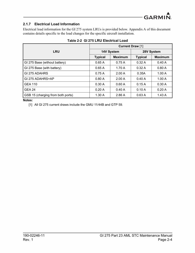
2.1.7 Electrical Load InformationElectrical load information for the GI 275 system LRUs is provided below. Appendix A of this document contains details specific to the load changes for the specific aircraft installation.
Table 2-2 GI 275 LRU Electrical Load
Notes:[1] All GI 275 current draws include the GMU 11/44B and GTP 59.
LRUCurrent Draw [1]
14V System 28V SystemTypical Maximum Typical Maximum
GI 275 Base (without battery) 0.65 A 0.75 A 0.32 A 0.40 AGI 275 Base (with battery) 0.65 A 1.70 A 0.32 A 0.80 AGI 275 ADAHRS 0.75 A 2.00 A 0.35A 1.00 AGI 275 ADAHRS+AP 0.80 A 2.00 A 0.40 A 1.00 AGEA 110 0.30 A 0.60 A 0.15 A 0.30 AGEA 24 0.20 A 0.40 A 0.10 A 0.20 AGSB 15 (charging from both ports) 1.30 A 2.86 A 0.63 A 1.43 A
190-02246-11 GI 275 Part 23 AML STC Maintenance ManualRev. 1 Page 2-5
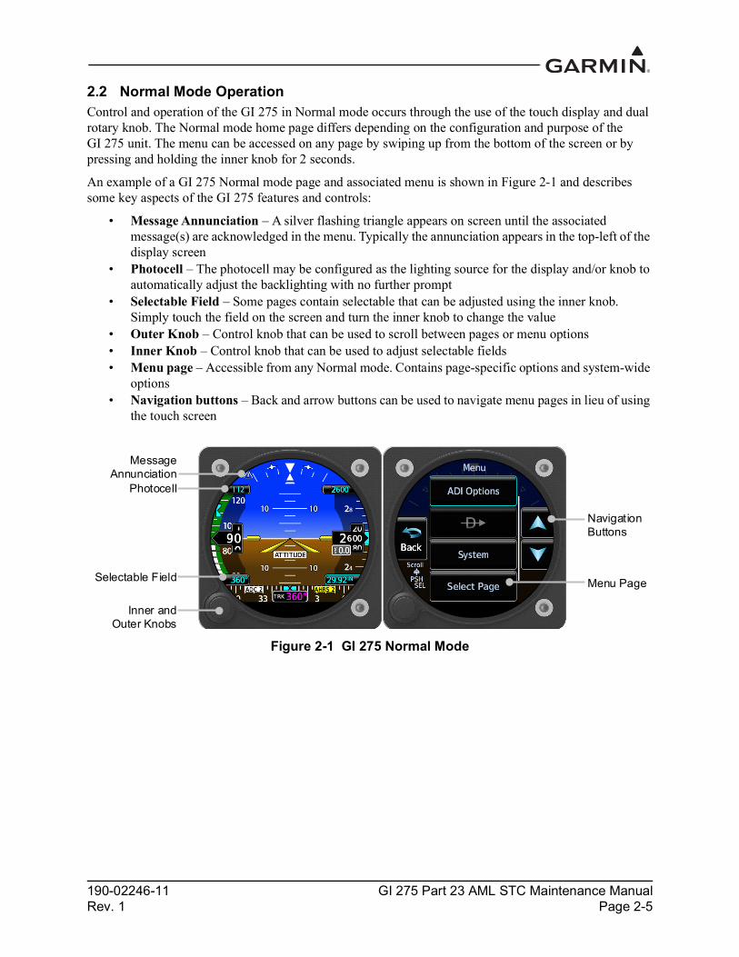
2.2 Normal Mode OperationControl and operation of the GI 275 in Normal mode occurs through the use of the touch display and dual rotary knob. The Normal mode home page differs depending on the configuration and purpose of the GI 275 unit. The menu can be accessed on any page by swiping up from the bottom of the screen or by pressing and holding the inner knob for 2 seconds.
An example of a GI 275 Normal mode page and associated menu is shown in Figure 2-1 and describes some key aspects of the GI 275 features and controls:
• Message Annunciation – A silver flashing triangle appears on screen until the associated message(s) are acknowledged in the menu. Typically the annunciation appears in the top-left of the display screen
• Photocell – The photocell may be configured as the lighting source for the display and/or knob to automatically adjust the backlighting with no further prompt
• Selectable Field – Some pages contain selectable that can be adjusted using the inner knob. Simply touch the field on the screen and turn the inner knob to change the value
• Outer Knob – Control knob that can be used to scroll between pages or menu options• Inner Knob – Control knob that can be used to adjust selectable fields• Menu page – Accessible from any Normal mode. Contains page-specific options and system-wide
options• Navigation buttons – Back and arrow buttons can be used to navigate menu pages in lieu of using
the touch screen
Figure 2-1 GI 275 Normal Mode
Navigation Buttons
Inner and Outer Knobs
Selectable Field
Photocell
Menu Page
Message Annunciation

190-02246-11 GI 275 Part 23 AML STC Maintenance ManualRev. 1 Page 2-6
2.3 Configuration Mode Operation2.3.1 Entering Configuration ModeThe Configuration mode of the GI 275 can be accessed by holding down the inner knob located at the bottom-left of the unit upon initial power-up. The knob must be pressed until the splash screen shown in Figure 2-2 appears. Touch Accept to proceed to the Configuration mode home page.
Figure 2-2 Entering Configuration Mode on the GI 275
2.3.2 Wireless ConnectivityThe GI 275 is capable of connecting to Wi-Fi and Bluetooth via the Garmin Pilot application to update flight databases. Refer to Section 5.14 of GI 275 Part 23 AML STC Installation Manual for procedures.
2.3.3 Import ConfigurationConfiguration settings can be imported via USB using the following procedure:
1. Power the GI 275 and all LRUs in the system on in Configuration mode.2. Insert the USB drive containing the configuration files into the USB dongle or GSB 15 (if
installed). A USB icon should appear on the left of the display once the GI 275 has recognized the device. If the icon doesn’t appear after 1 minute, remove the drive and re-insert it.
3. Navigate to the Config Options page (SW/Config → Config Options).4. Touch the Import Configuration button.5. Touch the Select Files button and select the configuration file to be imported.6. Touch the Select Configuration button.7. Select the applicable configurations and then touch the Back button.8. Touch the Import Config ( ) button and then touch the Start button.

190-02246-11 GI 275 Part 23 AML STC Maintenance ManualRev. 1 Page 2-7
2.3.4 Export ConfigurationConfiguration settings can be exported via USB using the following procedure:
1. Power the GI 275 and all LRUs in the system on in Configuration mode.2. Insert a USB drive into the USB dongle or GSB 15 (if installed). A USB icon should appear on the
left of the display once the GI 275 has recognized the device. If the icon doesn’t appear after 1 minute, remove the drive and re-insert it.
3. Navigate to the Config Options page (SW/Config → Config Options).4. Touch the Export Config button.5. Touch the Select Name field and enter a name for the saved file.6. Touch the Export Config button.

190-02246-11 GI 275 Part 23 AML STC Maintenance ManualRev. 1 Page 2-8
2.4 LRU Description, Control, and Operation2.4.1 GI 275 Display The GI 275 is a multi-function electronic instrument display. The GI 275 can be configured as a Primary ADI, HSI, MFD/Standby ADI, HSI/Standby ADI, MFD, or EIS display. The GI 275 ADAHRS and ADAHRS+AP variants include an integrated ADAHRS.
Figure 2-3 GI 275 Display
2.4.2 VFR GPS AntennaThe GI 275 has an internal VFR GPS that may be used as a primary GPS source for VFR navigation only or as a backup GPS. The internal VFR GPS is not approved as an IFR navigation source. If the VFR GPS antenna is installed, the internal VFR GPS is automatically used when the primary GPS source is unavailable. The GI 275 internal GPS antenna is installed on the instrument panel glareshield. Only one antenna is required for all installed GI 275s in the system. GPS data will be forwarded from the GI 275 directly interfaced to the GPS antenna.
Figure 2-4 VFR GPS Antenna
2.4.3 Integrated ADAHRSThe GI 275 ADAHRS and ADAHRS+AP variants have an integrated ADAHRS that provides altitude, vertical speed, airspeed, attitude, OAT, and heading data for flight instrumentation. The internal ADAHRS receives data from the GMU 11/44B, GTP 59, and pitot-static system. The integrated ADAHRS utilizes GPS signals sent from the internal VFR GPS or an external GPS/SBAS source. Attitude, heading, and air data can be sent to external LRUs via ARINC 429.
190-02246-11 GI 275 Part 23 AML STC Maintenance ManualRev. 1 Page 2-9
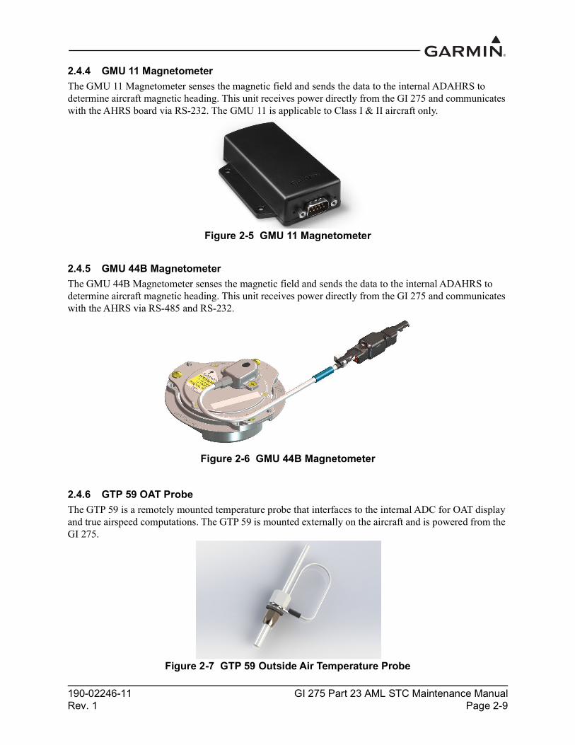
2.4.4 GMU 11 MagnetometerThe GMU 11 Magnetometer senses the magnetic field and sends the data to the internal ADAHRS to determine aircraft magnetic heading. This unit receives power directly from the GI 275 and communicates with the AHRS board via RS-232. The GMU 11 is applicable to Class I & II aircraft only.
Figure 2-5 GMU 11 Magnetometer
2.4.5 GMU 44B MagnetometerThe GMU 44B Magnetometer senses the magnetic field and sends the data to the internal ADAHRS to determine aircraft magnetic heading. This unit receives power directly from the GI 275 and communicates with the AHRS via RS-485 and RS-232.
Figure 2-6 GMU 44B Magnetometer
2.4.6 GTP 59 OAT ProbeThe GTP 59 is a remotely mounted temperature probe that interfaces to the internal ADC for OAT display and true airspeed computations. The GTP 59 is mounted externally on the aircraft and is powered from the GI 275.
Figure 2-7 GTP 59 Outside Air Temperature Probe

190-02246-11 GI 275 Part 23 AML STC Maintenance ManualRev. 1 Page 2-10
2.4.7 Backup BatteryThe backup battery is a lithium-iron battery that is required when the GI 275 is used as a primary or standby indicator. The battery will power the essential display sensors for a minimum of 60 minutes. The battery is charged by the aircraft electrical system when not in use. The backup battery is optional for GI 275 Base models and standard for GI 275 ADAHRS and ADAHRS+AP models.
Figure 2-8 Backup Battery
2.4.8 GSB 15The GSB 15 is an optional LRU that mounts into the instrument panel and provides two USB ports for charging and data transfer to a GI 275 unit. The USB ports can be used in place of a USB dongle to update the software on the GI 275 system and to charge devices while in-flight.
Figure 2-9 GSB 15 Charging Hub

190-02246-11 GI 275 Part 23 AML STC Maintenance ManualRev. 1 Page 2-11
2.4.9 EIS Components2.4.9.1 GEA 24 Engine Adapter The GEA 24 is a remotely mounted engine interface and monitoring module that gathers sensor input parameters from the engine and processes the signals for the GI 275. The GEA 24 communicates with the GI 275 via RS-232. The GEA 24 is applicable to Class I & II aircraft only.
Figure 2-10 GEA 24 Engine Adapter
2.4.9.2 GEA 110 Engine AdapterThe GEA 110 is a remote mount engine interface and monitoring module that gathers sensor input parameters from the engine and processes the signals for the GI 275. The GEA 110 communicates with the GI 275 via RS-485.
Figure 2-11 GEA 110 Engine Adapter
190-02246-11 GI 275 Part 23 AML STC Maintenance ManualRev. 1 Page 2-12
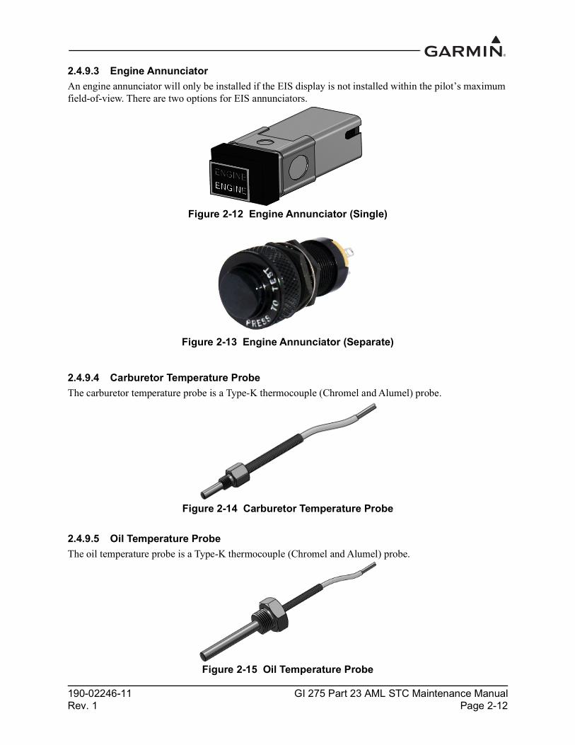
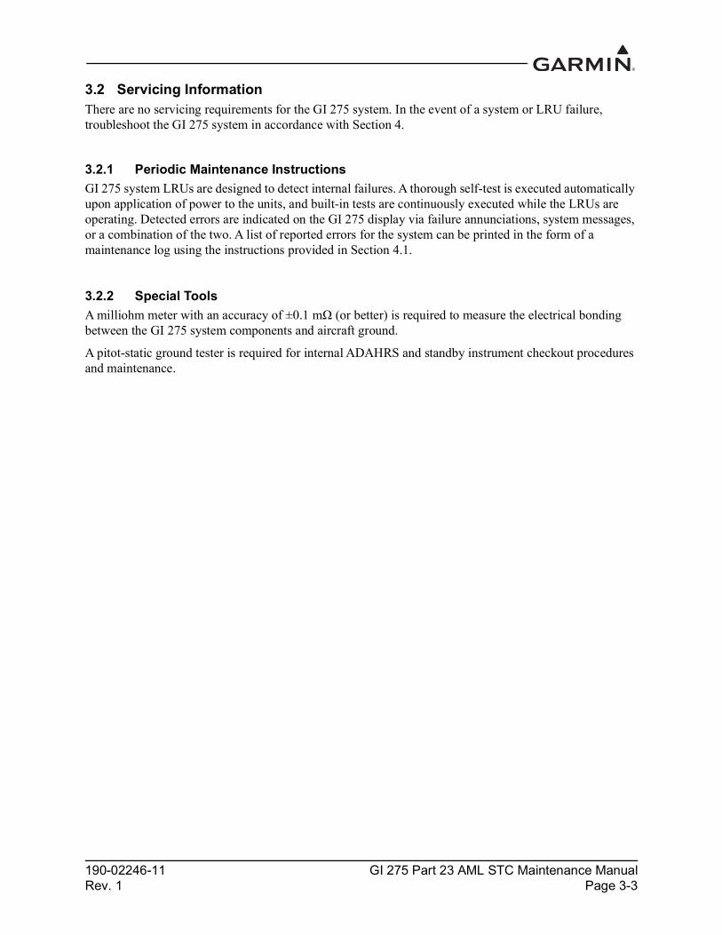
2.4.9.3 Engine AnnunciatorAn engine annunciator will only be installed if the EIS display is not installed within the pilot’s maximum field-of-view. There are two options for EIS annunciators.
Figure 2-12 Engine Annunciator (Single)
Figure 2-13 Engine Annunciator (Separate)
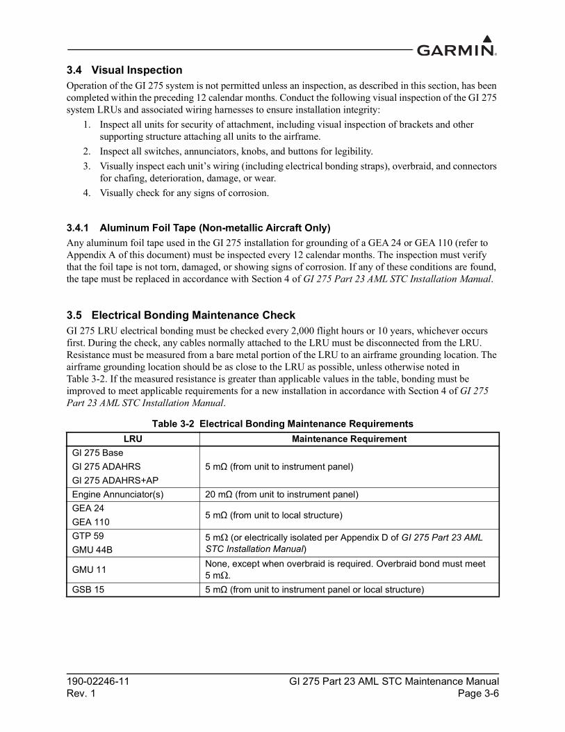
2.4.9.4 Carburetor Temperature ProbeThe carburetor temperature probe is a Type-K thermocouple (Chromel and Alumel) probe.
Figure 2-14 Carburetor Temperature Probe
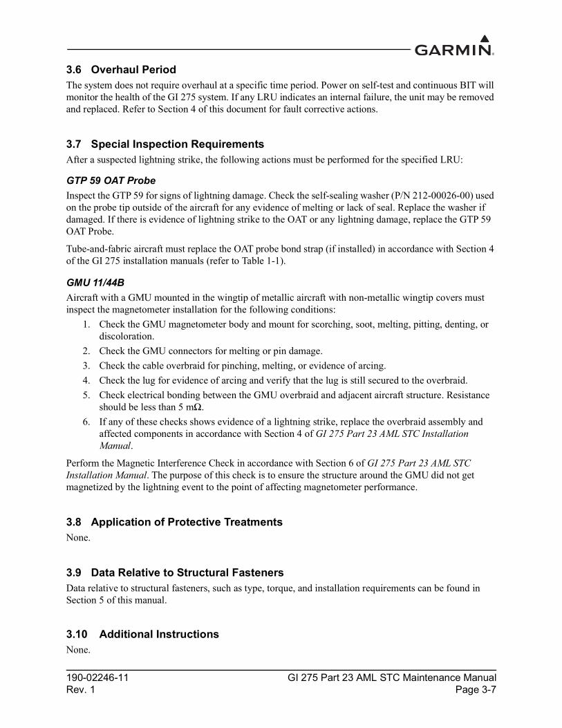
2.4.9.5 Oil Temperature ProbeThe oil temperature probe is a Type-K thermocouple (Chromel and Alumel) probe.
Figure 2-15 Oil Temperature Probe

190-02246-11 GI 275 Part 23 AML STC Maintenance ManualRev. 1 Page 2-13
2.4.9.6 Fuel Flow SensorsThe fuel flow sensor is incorporated in an aluminum housing that is installed in-line to the engine fuel supply. There are two STC approved options available for installation to suit most aircraft applications.
Figure 2-16 Fuel Flow Sensor FT-60 (Left) and FT-90 (Right)
2.4.9.7 Brass Pressure SensorsThe brass pressure sensors are small sensors that are supplied with a compatible plug. Depending on the installation, these sensors may be used to measure oil, fuel, and manifold pressure.
Figure 2-17 Brass Pressure Sensor
2.4.9.8 Stainless Steel Pressure SensorsThe stainless pressure sensors are unamplified, high-reliability sensors for harsh installation environments. There are four sensors available to measure oil, fuel, and manifold pressure.
Figure 2-18 Stainless Steel Pressure Sensor
2.4.9.9 P-Lead RPM PickupA wire with two parallel resistors in-line connects from each P-lead, at the Magneto or the ignition switch, to the GEA 24/110 to sense RPM.

190-02246-11 GI 275 Part 23 AML STC Maintenance ManualRev. 1 Page 3-1
3 INSTRUCTIONS FOR CONTINUED AIRWORTHINESS
3.1 Airworthiness Limitations ................................................................................................................3-23.2 Servicing Information .......................................................................................................................3-3
3.2.1 Periodic Maintenance Instructions .............................................................................................3-33.2.2 Special Tools ..............................................................................................................................3-3
3.3 Maintenance Intervals.......................................................................................................................3-43.4 Visual Inspection ..............................................................................................................................3-6
3.4.1 Aluminum Foil Tape (Non-metallic Aircraft Only)...................................................................3-63.5 Electrical Bonding Maintenance Check ...........................................................................................3-63.6 Overhaul Period ................................................................................................................................3-73.7 Special Inspection Requirements......................................................................................................3-73.8 Application of Protective Treatments ...............................................................................................3-73.9 Data Relative to Structural Fasteners................................................................................................3-73.10 Additional Instructions .....................................................................................................................3-7

190-02246-11 GI 275 Part 23 AML STC Maintenance ManualRev. 1 Page 3-3
3.2 Servicing InformationThere are no servicing requirements for the GI 275 system. In the event of a system or LRU failure, troubleshoot the GI 275 system in accordance with Section 4.
3.2.1 Periodic Maintenance InstructionsGI 275 system LRUs are designed to detect internal failures. A thorough self-test is executed automatically upon application of power to the units, and built-in tests are continuously executed while the LRUs are operating. Detected errors are indicated on the GI 275 display via failure annunciations, system messages, or a combination of the two. A list of reported errors for the system can be printed in the form of a maintenance log using the instructions provided in Section 4.1.
3.2.2 Special ToolsA milliohm meter with an accuracy of ±0.1 mΩ (or better) is required to measure the electrical bonding between the GI 275 system components and aircraft ground.
A pitot-static ground tester is required for internal ADAHRS and standby instrument checkout procedures and maintenance.

190-02246-11 GI 275 Part 23 AML STC Maintenance ManualRev. 1 Page 3-4
3.3 Maintenance IntervalsTable 3-1 Periodic Maintenance
Item Description/ Procedure Interval
GI 275 System Visual Inspection
All installed system LRUs, switches, knobs, and wiring harnesses must be inspected to ensure continued integrity of the installation. The inspection must be performed in accordance with Section 3.4.
12 calendar months
Backup Battery Check
If installed, perform a Backup Battery Check as described in Section 5.12.5.
If the backup battery does not pass the Backup Battery Check, it must be replaced using the procedure found in Section 5.5.
12 calendar months
EIS Annunciator Lamp Check
If an EIS annunciator(s) is installed, perform a check of the annunciator lamps using the following procedure:1. Power on the GI 275 directly interfaced to the annunciator
in Configuration mode.2. Navigate to Diagnostics → Discrete Outputs.3. Toggle the state of the Engine Caution and Engine Warning
discrete outputs to Active. 4. Verify that the respective engine annunciator lights have
illuminated. 5. Toggle the state of the Engine Caution and Engine Warning
discrete outputs to Inactive.
12 calendar months
AHRS Magnetic Field Model Update
The GI 275 Integrated ADAHRS utilizes an Earth magnetic field model that is updated once every 5 years as part of the Aviation Database maintained by the owner/operator. If the magnetic model is not up-to-date, the unit will issue an alert upon start-up indicating the model has expired. A Service Bulletin containing the updated magnetic field model and instructions for installation can be obtained from the Dealer Resource Center or by contacting Garmin.
Every 5 years
Electrical Bonding Check
Perform an electrical bonding check of the GI 275 system LRUs in accordance with Section 3.5.
Every 2000 flight hours or 10 years, whichever comes first
Altimeter ChecksTest according to 14 CFR §43 Appendix E. Refer to the pitot-static checkout procedure in Section 5.14.2 for system-specific checkout procedure.
Interval must be in accordance with Title 14 CFR §91.411 and 91.413
Lightning Damage Check
Conduct an inspection of the GI 275 system in accordance with Section 3.7.
After a suspected or actual lightning strike
Equipment Removal and Replacement
Removal and replacement of the GI 275 system LRUs can be accomplished by referring to Section 5 for instructions. On Condition

190-02246-11 GI 275 Part 23 AML STC Maintenance ManualRev. 1 Page 3-5
Cleaning GI 275 Touchscreen
The display can be cleaned with a soft cotton cloth dampened with clean water. DO NOT use any chemical cleaning agents. Care should be taken to avoid scratching the surface of the display.
On Condition
Display Backlight
Over time, the backlight lamp may dim and the display may not perform as well in direct sunlight conditions. The user must determine by observation when the display brightness is not suitable for its intended use. Contact a Garmin authorized repair station when the backlight lamp requires service.
On Condition
Item Description/ Procedure Interval
190-02246-11 GI 275 Part 23 AML STC Maintenance ManualRev. 1 Page 3-6
3.4 Visual InspectionOperation of the GI 275 system is not permitted unless an inspection, as described in this section, has been completed within the preceding 12 calendar months. Conduct the following visual inspection of the GI 275 system LRUs and associated wiring harnesses to ensure installation integrity:
1. Inspect all units for security of attachment, including visual inspection of brackets and other supporting structure attaching all units to the airframe.
2. Inspect all switches, annunciators, knobs, and buttons for legibility.3. Visually inspect each unit’s wiring (including electrical bonding straps), overbraid, and connectors
for chafing, deterioration, damage, or wear.4. Visually check for any signs of corrosion.
3.4.1 Aluminum Foil Tape (Non-metallic Aircraft Only)Any aluminum foil tape used in the GI 275 installation for grounding of a GEA 24 or GEA 110 (refer to Appendix A of this document) must be inspected every 12 calendar months. The inspection must verify that the foil tape is not torn, damaged, or showing signs of corrosion. If any of these conditions are found, the tape must be replaced in accordance with Section 4 of GI 275 Part 23 AML STC Installation Manual.
3.5 Electrical Bonding Maintenance CheckGI 275 LRU electrical bonding must be checked every 2,000 flight hours or 10 years, whichever occurs first. During the check, any cables normally attached to the LRU must be disconnected from the LRU. Resistance must be measured from a bare metal portion of the LRU to an airframe grounding location. The airframe grounding location should be as close to the LRU as possible, unless otherwise noted in Table 3-2. If the measured resistance is greater than applicable values in the table, bonding must be improved to meet applicable requirements for a new installation in accordance with Section 4 of GI 275 Part 23 AML STC Installation Manual.
Table 3-2 Electrical Bonding Maintenance RequirementsLRU Maintenance Requirement
GI 275 BaseGI 275 ADAHRSGI 275 ADAHRS+AP
5 mΩ (from unit to instrument panel)
Engine Annunciator(s) 20 mΩ (from unit to instrument panel)GEA 24GEA 110
5 mΩ (from unit to local structure)
GTP 59GMU 44B
5 mΩ (or electrically isolated per Appendix D of GI 275 Part 23 AML STC Installation Manual)
GMU 11 None, except when overbraid is required. Overbraid bond must meet 5 mΩ.
GSB 15 5 mΩ (from unit to instrument panel or local structure)
190-02246-11 GI 275 Part 23 AML STC Maintenance ManualRev. 1 Page 3-7
3.6 Overhaul PeriodThe system does not require overhaul at a specific time period. Power on self-test and continuous BIT will monitor the health of the GI 275 system. If any LRU indicates an internal failure, the unit may be removed and replaced. Refer to Section 4 of this document for fault corrective actions.
3.7 Special Inspection RequirementsAfter a suspected lightning strike, the following actions must be performed for the specified LRU:
GTP 59 OAT ProbeInspect the GTP 59 for signs of lightning damage. Check the self-sealing washer (P/N 212-00026-00) used on the probe tip outside of the aircraft for any evidence of melting or lack of seal. Replace the washer if damaged. If there is evidence of lightning strike to the OAT or any lightning damage, replace the GTP 59 OAT Probe.
Tube-and-fabric aircraft must replace the OAT probe bond strap (if installed) in accordance with Section 4 of the GI 275 installation manuals (refer to Table 1-1).
GMU 11/44BAircraft with a GMU mounted in the wingtip of metallic aircraft with non-metallic wingtip covers must inspect the magnetometer installation for the following conditions:
1. Check the GMU magnetometer body and mount for scorching, soot, melting, pitting, denting, or discoloration.
2. Check the GMU connectors for melting or pin damage.3. Check the cable overbraid for pinching, melting, or evidence of arcing.4. Check the lug for evidence of arcing and verify that the lug is still secured to the overbraid.5. Check electrical bonding between the GMU overbraid and adjacent aircraft structure. Resistance
should be less than 5 mΩ.6. If any of these checks shows evidence of a lightning strike, replace the overbraid assembly and
affected components in accordance with Section 4 of GI 275 Part 23 AML STC Installation Manual.
Perform the Magnetic Interference Check in accordance with Section 6 of GI 275 Part 23 AML STC Installation Manual. The purpose of this check is to ensure the structure around the GMU did not get magnetized by the lightning event to the point of affecting magnetometer performance.
3.8 Application of Protective TreatmentsNone.
3.9 Data Relative to Structural FastenersData relative to structural fasteners, such as type, torque, and installation requirements can be found in Section 5 of this manual.
3.10 Additional InstructionsNone.

190-02246-11 GI 275 Part 23 AML STC Maintenance ManualRev. 1 Page 4-1
4 TROUBLESHOOTING
4.1 General System Troubleshooting......................................................................................................4-24.1.1 System Maintenance Log ...........................................................................................................4-2
4.2 Connector Information......................................................................................................................4-34.2.1 GI 275.........................................................................................................................................4-34.2.2 GEA 24.......................................................................................................................................4-74.2.3 GEA 110...................................................................................................................................4-114.2.4 GMU 44B.................................................................................................................................4-144.2.5 GMU 11....................................................................................................................................4-154.2.6 GTP 59 .....................................................................................................................................4-164.2.7 GSB 15 .....................................................................................................................................4-16
4.3 Troubleshooting Flow Charts .........................................................................................................4-17
This section provides information to assist troubleshooting if fault codes are displayed on the GI 275 or problems occur after completing system maintenance. Refer to Appendix A of this document retained in the aircraft permanent records for a list of the interfaced equipment and system configuration data. When troubleshooting the GI 275 system, refer to wire routing drawings and interconnect diagrams retained in Appendix A of this document or with the aircraft’s permanent records.

190-02246-11 GI 275 Part 23 AML STC Maintenance ManualRev. 1 Page 4-2
4.1 General System TroubleshootingBefore troubleshooting the GI 275 system, print the current configuration log using the procedure in Section 2.3.4 to ensure that system configuration settings match those recorded in the aircraft’s permanent records as applicable to the aircraft’s current configuration.
If the GI 275 configuration does not match the configuration log retained with the aircraft permanent records, load the saved configuration from the USB drive retained with the aircraft records. If this cannot be accomplished, or does not correct the configuration, the issue must be corrected by a Garmin dealer using the configuration instructions provided in Section 5 of the GI 275 installation manuals (refer to Table 1-1). Basic troubleshooting of the GI 275 system can be accomplished using the instructions provided in Table 4-1.
Table 4-1 GI 275 Failures
4.1.1 System Maintenance LogThe GI 275 system has a maintenance and error log that can be accessed or printed to assist with system maintenance and troubleshooting.
The maintenance and error log can be printed using the following procedure: 1. Power on all GI 275s in the system in Configuration mode in accordance with Section 2.3.1.2. Insert a USB drive into the USB dongle or GSB 15 (if installed). A USB icon should appear on the
left of the display once the GI 275 has recognized the device. If the icon doesn’t appear after 1 minute, remove the drive and re-insert it.
3. Navigate to the Maintenance page.4. Press the Export Logs button.5. Select which log to download: Assert, Flight Data, Aircraft Report, or Fault Log.
For downloading Flight Data logs, select the desired option for the Download Log Style and enter the applicable date if downloading flight data logs for a specific date
6. Press the Start Download button.7. Once the save process is completed, disconnect the USB drive and insert it into a computer.8. On the computer, navigate to the USB drive and open the “maintenance_logs” directory.9. Open the .htm file.10. The file should open in your computer’s Internet browser and can be printed using your selected
Internet browser print function (in most cases, pressing Ctrl + P buttons simultaneously will access this function).
The maintenance log will display reported system faults. The alert message that is displayed on the GI 275 for that fault (if any) will display frequency, most recent occurrence time of the fault, and any additional information about the fault that might be helpful. If any faults are reported on the maintenance log, refer to the troubleshooting flowcharts contained in Section 4.3.
Symptom Recommended ActionGI 275 screen is blank Check power/ground wiring for GI 275.
EIS Gauge Fault/Failure Troubleshoot the problem using the EIS gauge troubleshooting flowchart provided in Section 4.3.
An alert message is displayed on the GI 275 or present in the maintenance log
Troubleshoot the alert message using the flowcharts provided in Section 4.3.

190-02246-11 GI 275 Part 23 AML STC Maintenance ManualRev. 1 Page 4-3
4.2 Connector InformationThis section contains connector information and description of pin functions for all LRUs that can be installed as part of the GI 275 STC.
4.2.1 GI 275
NOTEThe J2752/P2752 connector is only included with GI 275 ADAHRS and ADAHRS+AP models.
GI 275 displays have up to three connectors:• J2751/P2751 - 78 pin female contact HD D-sub • J2752/P2752 - 78 pin female contact HD D-sub (GI 275 ADAHRS and ADAHRS+AP units only)• BNC, Male
Figure 4-1 GI 275 Connectors

190-02246-11 GI 275 Part 23 AML STC Maintenance ManualRev. 1 Page 4-4
Figure 4-2 GI 275 J2751 Connector (Looking at Connector)
Table 4-2 J2751/P2751 ConnectorPin Function I/O Pin Function I/O1 CONFIG MODULE GROUND -- 40 CONFIG MODULE DATA I/O2 AIRCRAFT POWER 1 IN 41 AIRCRAFT GROUND --3 AIRCRAFT POWER 2 IN 42 LIGHTING BUS LO IN4 DISCRETE OUT 1 LO OUT 43 DISCRETE OUT 2* OUT5 VOR/LOC COMPOSITE LO IN 44 VOR/LOC COMPOSITE HI IN6 GLIDESLOPE DEVIATION +UP IN 45 GLIDESLOPE DEV +DOWN IN7 LATERAL -FLAG IN 46 ETHERNET OUT 1A OUT8 ETHERNET OUT 2A OUT 47 ETHERNET OUT 1B OUT9 ETHERNET OUT 2B OUT 48 ALERT AUDIO OUT LO OUT10 OBS STATOR F OUT 49 RS-485 A I/O11 GLIDESLOPE +FLAG IN 50 TO/FROM +FLAG IN IN12 DISCRETE IN 4 LO IN 51 SPARE GROUND --13 OBS ROTOR H IN 52 ARINC 429 IN 1A IN14 ARINC 429 IN 2B IN 53 ARINC 429 IN 3A IN15 ARINC 429 IN 4B IN 54 SPARE GROUND --16 ARINC 429 OUT 1A OUT 55 ARINC 429 OUT 1B OUT17 SPARE GROUND -- 56 SPARE GROUND --18 RS-232 OUT 2 OUT 57 RS-232 IN 1 IN19 LRU GROUND -- 58 USB DATA HI I/O20 LRU POWER OUT 59 USB GROUND --21 CONFIG MODULE POWER OUT 60 CONFIG MODULE CLOCK OUT22 LIGHTING BUS HI IN 61 AIRCRAFT GROUND --23 DISCRETE IN 1 LO IN 62 DISCRETE IN 2 LO IN24 DISCRETE OUT 3 LO OUT 63 DISCRETE IN 3 LO IN25 LATERAL DEVIATION +LEFT IN 64 LATERAL DEVIATION +RIGHT IN26 LATERAL +FLAG IN 65 ETHERNET IN 1A IN27 ETHERNET IN 2A IN 66 ETHERNET IN 1B IN28 ETHERNET IN 2B IN 67 OBS STATOR G IN29 OBS STATOR D OUT 68 OBS STATOR E OUT30 ALERT AUDIO OUT HI OUT 69 RS-485 B I/O31 GLIDESLOPE -FLAG IN 70 SPARE GROUND --32 TO/FROM -FLAG IN 71 OBS ROTOR C IN33 ARINC 429 IN 1B IN 72 ARINC 429 IN 2A IN34 ARINC 429 IN 3B IN 73 ARINC 429 IN 4A IN35 ARINC 429 OUT 2A OUT 74 ARINC 429 OUT 2B OUT36 SPARE GROUND -- 75 SPARE GROUND --37 RS-232 IN 2 IN 76 RS-232 2 GROUND --38 RS-232 OUT 1 OUT 77 RS-232 1 GROUND --39 USB DATA LO I/O 78 USB VBUS POWER OUT
63 64 65 66 67 68 69 70 71 72 73 74 75 76 77 78626160
595857565554535251
1 2 3 4 5 6 7 8 9 10 11 13 14 15 16 1712 19 20
21 25242322
18
26 27 28 29 30 31 32 33 34 35 36 37 38 39
40 41 42 43 44 504948474645

190-02246-11 GI 275 Part 23 AML STC Maintenance ManualRev. 1 Page 4-5
Figure 4-3 GI 275 J2752 Connector (Looking at Connector)
CAUTIONPins highlighted in gray are not present in GI 275 ADAHRS units (P/Ns 011-04489-10 and 011-04489-30) and should be treated as Not Connected. All pins listed in Table 4-3 are present in GI 275 ADAHRS+AP units (P/Ns 011-04489-20 and 011-04489-40).
Table 4-3 J2752/P2752 ConnectorPin Function I/O Pin Function I/O1 DISCRETE OUT 7 LO OUT 40 DISCRETE OUT 8 LO OUT2 SPARE -- 41 AP INTERLOCK RELAY COM IN3 GYRO VALID COMMON -- 42 GYRO VALID RELAY NC OUT4 DISCRETE IN 5 LO IN 43 DISCRETE IN 6 LO IN5 VERTICAL -FLAG OUT OUT 44 VERTICAL SUPERFLAG OUT6 PITCH AC OUT HI OUT 45 ROLL AC OUT LO --7 26 VAC REF LO IN 46 10 VAC REF LO IN8 HEADING SYNCRO X OUT 47 HEADING SYNCHRO Z IN9 VERTICAL +UP OUT OUT 48 LATERAL +LEFT OUT OUT10 LATERAL +RIGHT OUT OUT 49 TO/FROM -FLAG OUT OUT11 RADAR ROLL HI OUT 50 RADAR ROLL LO --12 CAN LO I/O 51 CAN TERMINATION A I/O13 A/P HEADING ERROR HI OUT 52 A/P HEADING ERROR LO OUT14 DISCRETE OUT 5 LO OUT 53 SPARE --15 YAW RATE HI OUT 54 BARO CORRECTION LO IN16 HEADING SYNCRO Y OUT 55 PITCH DC OUT OUT17 DISCRETE OUT 9 LO OUT 56 RS-232 IN 3 IN18 FD ENABLE HI IN 57 SPARE --19 FD PITCH UP IN 58 FD PITCH DOWN IN20 DISCRETE OUT 6 LO OUT 59 SPARE GROUND --21 OAT PROBE IN LO IN 60 OAT PROBE IN HI IN22 AP INTERLOCK RELAY NC -- 61 AP INTERLOCK RELAY NO OUT23 GYRO VALID RELAY NO OUT 62 OAT PROBE POWER OUT24 VERTICAL +FLAG OUT OUT 63 LATERAL +FLAG OUT OUT25 LATERAL SUPER FLAG OUT 64 PITCH AC OUT LO OUT26 ROLL AC OUT HI OUT 65 26 VAC REF HI IN27 10 VAC REF HI IN 66 LATERAL -FLAG OUT OUT28 SPARE -- 67 SPARE GROUND --29 TO/FROM +FLAG OUT 68 VERTICAL +DOWN OUT OUT30 RADAR PITCH LO -- 69 RADAR PITCH HI OUT31 CAN HI I/O 70 CAN TERMINATION I/O32 A/P COURSE ERROR HI OUT 71 A/P COURSE ERROR LO OUT33 SPARE -- 72 DISCRETE OUT 4 LO OUT34 ROLL DC OUT OUT 73 YAW RATE LO --35 BARO CORRECTION HI OUT 74 SPARE GROUND --
63646566676869707172737475767778 62 61 60
59 58 57 56 55 54 53 52 51
12345678910111314151617 121920
2125 24 23 22
18
2627282930313233343536373839
404142434450 49 48 47 46 45
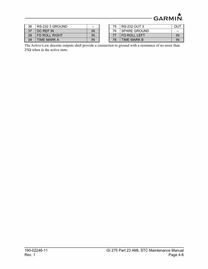
190-02246-11 GI 275 Part 23 AML STC Maintenance ManualRev. 1 Page 4-6
The Active-Low discrete outputs shall provide a connection to ground with a resistance of no more than 25Ω when in the active state.
36 RS-232 3 GROUND -- 75 RS-232 OUT 3 OUT37 DC REF IN IN 76 SPARE GROUND --38 FD ROLL RIGHT IN 77 FD ROLL LEFT IN39 TIME MARK A IN 78 TIME MARK B IN

190-02246-11 GI 275 Part 23 AML STC Maintenance ManualRev. 1 Page 4-7
4.2.2 GEA 24The GEA 24 has four connectors:
• J241/P241 9-pin male contact HD D-sub• J242/P242 25-pin female contact HD D-sub• J243/P243 37-pin male contact HD D-sub• J244/P244 50-pin male contact HD D-sub
Figure 4-4 GEA 24 Connectors
GEA 24 UNIT011-02848-00
J243
J242
J244
J241

190-02246-11 GI 275 Part 23 AML STC Maintenance ManualRev. 1 Page 4-8
Figure 4-5 GEA 24 J241/P241 Connector (Looking at the Connector)
Table 4-4 J241/P241 Connector
Figure 4-6 GEA J242/P242 Connector (Looking at the Connector)
Table 4-5 J242/P242 Connector
Pin Function I/O1 CAN HI I/O2 CAN LO I/O3 RESERVED --4 RS-232 RX IN5 RS-232 TX OUT6 GROUND --7 AIRCRAFT POWER 1 IN8 AIRCRAFT POWER 2 IN9 GROUND --
Pin Function I/O Pin Function I/O1 RESERVED -- 14 CHT 6 HI / CHT 2 RESIST HI IN2 CHT 6 LO / CHT 2 RESIST LO IN 15 EGT 6 HI IN3 EGT 6 LO IN 16 CHT 5 / CHT 1 RESISTIVE HI IN4 CHT 5 LO / CHT 1 RESIST LO IN 17 EGT 5 HI IN5 EGT 5 LO IN 18 CHT 4 HI IN6 CHT 4 LO IN 19 EGT 4 HI IN7 EGT 4 LO IN 20 CHT 3 HI IN8 CHT 3 LO IN 21 EGT 3 HI IN9 EGT 3 LO IN 22 CHT 2 HI IN10 CHT 2 LO IN 23 EGT 2 HI IN11 EGT 2 LO IN 24 CHT 1 HI IN12 CHT 1 LO IN 25 EGT 1 HI IN13 EGT 1 LO IN

190-02246-11 GI 275 Part 23 AML STC Maintenance ManualRev. 1 Page 4-9
Figure 4-7 GEA 24 J243/P243 Connector (Looking at Connector)
Table 4-6 J243/P243 ConnectorPin Function I/O Pin Function I/O1 FUEL PRESS GROUND -- 20 FUEL XDCR GROUND_1 --
2 FUEL PRESS IN 21 FUEL RETURN (shared w/Pin 37, J244 connector) IN
3 FUEL PRESS XDCR +12V OUT 22 FUEL XDCR GROUND_2
4 FUEL PRESS XDCR +5V OUT 23 FUEL FLOW (shared w/Pin 36, J244 connector) IN
5 RPM XDCR GROUND_2 -- 24 FUEL XDCR +12V_1 OUT6 RPM 2 IN 25 FUEL XDCR +12V_2 OUT7 RPM XDCR GROUND_1 -- 26 GP +5V_1 OUT8 RPM 1 IN 27 GP GROUND_1 --9 RPM XDCR +12V_1 OUT 28 POS 7 / TIT 2 / MISC TEMP 2 LO IN
10 RPM XDCR +12V_2 OUT 29 POS 7 / TIT 2 / MISC TEMP 2 HI IN11 RESERVED / SPARE IN 30 POS 6 / TIT 1 / MISC TEMP 1 LO IN12 MANIFOLD PRESS GROUND -- 31 POS 6 / TIT 1 / MISC TEMP 1 HI IN13 MANIFOLD PRESS IN 32 OIL TEMP LO IN14 MANIFOLD PRESS XDCR +12V OUT 33 OIL TEMP HI IN
15 MANIFOLD PRESS XDCR +5V OUT 34 SHUNT 2 LO (shared w/Pin 47, J244 connector) IN
16 OIL PRESS GROUND -- 35 SHUNT 2 HI (shared w/Pin 46, J244 connector) IN
17 OIL PRESS HI IN 36 SHUNT 1 LO IN18 OIL PRESS XDCR +12V OUT 37 SHUNT 1 HI IN19 OIL PRESS XDCR +5V OUT

190-02246-11 GI 275 Part 23 AML STC Maintenance ManualRev. 1 Page 4-10
Figure 4-8 GEA 24 J244/P244 Connector (Looking at the Connector)
Table 4-7 J244/P244 Connector
*Indicates Active-Low**Can be configured as Active-High or Active-Low
Pin Function I/O Pin Function I/O1 SYSTEM ID 1A* IN 26 GP GROUND_2 --2 SYSTEM ID 1B / GROUND -- 27 GP +5V_3 OUT3 RESERVED -- 28 VOLTS 2 IN4 RESERVED -- 29 GP GROUND 3 --5 FUEL QTY +5V_1 OUT 30 POS 5 HI / +5V OUT6 FUEL QTY 1 IN 31 POS 5 / MISC PRESS IN7 FUEL QTY 1 GROUND -- 32 POS 5 LO / GROUND --8 FUEL QTY +5V_2 OUT 33 CAN2_L I/O9 FUEL QTY 2 IN 34 FUEL XDCR +12V_3 OUT10 FUEL QTY 2 GROUND -- 35 FUEL XDCR +12V_4 OUT
11 POS 3 HI / +5V_3 OUT 36 FUEL FLOW (shared w/Pin 23, J243 connector) IN
12 POS 3 / GP 3 / FUEL QTY 3 IN 37 FUEL RETURN (shared w/Pin 21, J243 connector) IN
13 POS 3 LO / GROUND -- 38 FUEL XDCR GND_3 --14 POS 4 HI / +5V_4 OUT 39 FUEL XDCR GND_4 --15 POS 4 / GP 4 / FUEL QTY 4 IN 40 DISCRETE IN 1** IN16 POS 4 LO / GROUND -- 41 DISCRETE IN 2** IN17 CAN2_H I/O 42 DISCRETE IN 3** IN18 GP1 HI / +5V OUT 43 DISCRETE IN 4** IN
19 GP1 / POS 1 IN 44 DISCRETE OUT 1* / MASTER WARNING IN
20 GP1 LO / GROUND -- 45 DISCRETE OUT 2* / MASTER CAUTION IN
21 GP2 HI / +5V OUT 46 SHUNT 2 HI (shared w/Pin 35, J243 connector) IN
22 GP2 / POS 2 IN 47 SHUNT 2 LO (shared w/Pin 34, J243 connector) IN
23 GP2 LO / GOURND -- 48 RESERVED / SPARE 1 IN24 GP +5V_2 OUT 49 RESERVED / SPARE 2 IN25 VOLTS 1 IN 50 GP +12V OUT
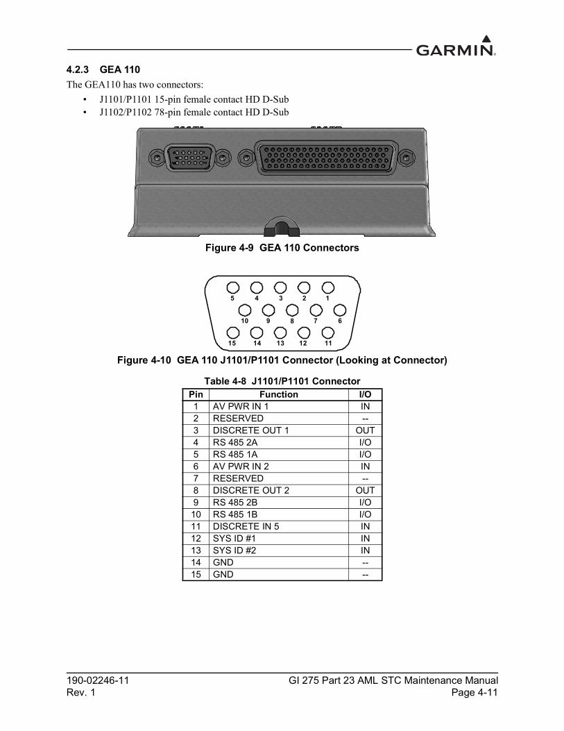
190-02246-11 GI 275 Part 23 AML STC Maintenance ManualRev. 1 Page 4-11
4.2.3 GEA 110The GEA110 has two connectors:
• J1101/P1101 15-pin female contact HD D-Sub • J1102/P1102 78-pin female contact HD D-Sub
Figure 4-9 GEA 110 Connectors
Figure 4-10 GEA 110 J1101/P1101 Connector (Looking at Connector)
Table 4-8 J1101/P1101 ConnectorPin Function I/O1 AV PWR IN 1 IN2 RESERVED --3 DISCRETE OUT 1 OUT4 RS 485 2A I/O5 RS 485 1A I/O6 AV PWR IN 2 IN7 RESERVED --8 DISCRETE OUT 2 OUT9 RS 485 2B I/O10 RS 485 1B I/O11 DISCRETE IN 5 IN12 SYS ID #1 IN13 SYS ID #2 IN14 GND --15 GND --
15 14 13 12 11
10 9 8 7 6
5 4 3 2 1

190-02246-11 GI 275 Part 23 AML STC Maintenance ManualRev. 1 Page 4-12
Figure 4-11 GEA 110 J1102/P1102 Connector Looking at Unit
Table 4-9 J1102/P1102 ConnectorPin Function I/O Pin Function I/O1 CHT 1 (+) IN 40 EGT 1 (+) IN2 CHT 2 (+) IN 41 EGT 2 (+) IN3 CHT 3 (+) IN 42 EGT 3 (+) IN4 CHT 4 (+) IN 43 EGT 4 (+) IN5 CHT 5 (+) IN 44 EGT 5 (+) IN6 CHT 6 (+) IN 45 EGT 6 (+) IN7 GENERAL PURPOSE 1 (+) IN 46 CARB TEMP (+) IN8 GENERAL PURPOSE 2 (+) IN 47 OIL TEMP (+) IN9 +10 VDC OUT 48 OIL PRESSURE (+) IN10 FUEL PRESSURE (+) IN 49 GND --11 DISCRETE IN 1 IN 50 MANIFOLD PRESSURE (+) IN
12 FUEL QUANTITY 1 / GENERAL PURPOSE 3 (+) IN 51 DISCRETE IN 3 IN
13 FUEL QUANTITY 3 /GENERAL PURPOSE 5 (+) IN 52 FUEL QUANTITY 2 /
GENERAL PURPOSE 4 (+) IN
14 GND IN 53 FUEL QUANTITY 4 /GENERAL PURPOSE 6 (+) IN
15 FUEL FLOW 1 IN 54 GND --16 FUEL FLOW 2 IN 55 SHUNT 1 (-) IN17 +12 VDC OUT 56 SHUNT 2 (-) IN18 RPM IN 1 (+) IN 57 BUS 1 IN19 RPM IN 2 (+) IN 58 BUS 2 IN20 CONFIG MOD PWR OUT 59 CONFIG MOD CLOCK OUT21 CHT 1 (-) IN 60 EGT 1 (-) IN22 CHT 2 (-) IN 61 EGT 2 (-) IN23 CHT 3 (-) IN 62 EGT 3 (-) IN24 CHT 4 (-) IN 63 EGT 4 (-) IN25 CHT 5 (-) IN 64 EGT 5 (-) IN26 CHT 6 (-) IN 65 EGT 6 (-) IN27 GENERAL PURPOSE 1 (-) IN 66 CARB TEMP (-) IN28 GENERAL PURPOSE 2 (-) IN 67 OIL TEMP (-) IN29 +5 VDC OUT 68 OIL PRESSURE (-) IN30 FUEL PRESSURE (-) IN 69 +12 VDC OUT31 DISCRETE IN 2 IN 70 MANIFOLD PRESSURE (-) IN
32 FUEL QUANTITY 1 /GENERAL PURPOSE 3 (-) IN 71 DISCRETE IN 4 IN
33 FUEL QUANTITY 3 /GENERAL PURPOSE 5 (-) IN 72 FUEL QUANTITY 2 /
GENERAL PURPOSE 4 (-) IN
34 GND -- 73 FUEL QUANTITY 4 /GENERAL PURPOSE 6 (-) IN
63646566676869707172737475767778 62 61 60
59 58 57 56 55 54 53 52 51
12345678910111314151617 121920
2125 24 23 22
18
2627282930313233343536373839
404142434450 49 48 47 46 45

190-02246-11 GI 275 Part 23 AML STC Maintenance ManualRev. 1 Page 4-13
35 SHUNT 1 (+) IN 74 GND --36 SHUNT 2 (+) IN 75 SPARE --37 RPM IN 1 (-) IN 76 +5 VDC OUT38 RPM IN 2 (-) IN 77 BUS 3 IN39 CONFIG MOD DATA I/O 78 CONFIG MOD GND --

190-02246-11 GI 275 Part 23 AML STC Maintenance ManualRev. 1 Page 4-14
4.2.4 GMU 44BThe GMU 44B has one connector:
• J442/P442 6-pin rectangular connector
Figure 4-12 J442/P442 Connector
Table 4-10 J442/P442 ConnectorPin Function I/O1 SHIELD GROUND --2 RS-422 OUT B OUT3 RS-422 OUT A OUT4 POWER GROUND --5 RS-232 IN IN6 MAG POWER INPUT IN

190-02246-11 GI 275 Part 23 AML STC Maintenance ManualRev. 1 Page 4-15
4.2.5 GMU 11The GMU 11 has one connector:
• J111/P111 9-pin female connector
Figure 4-13 GMU 11 Connector
Table 4-11 J111/P111 ConnectorPin Function I/O1 CAN BUS HI I/O2 CAN BUS LO I/O3 UNIT ID 1 IN4 RS-232 IN IN5 RS-232 OUT OUT6 SIGNAL GROUND --7 AIRCRAFT PWR 1 IN8 AIRCRAFT PWR 2 IN9 POWER GROUND --

190-02246-11 GI 275 Part 23 AML STC Maintenance ManualRev. 1 Page 4-16
4.2.6 GTP 59The GTP 59 Temperature Probe does not have a connector. Rather, a 3-conductor shielded cable extends from the sensor for interface with a GI 275 or GDC unit.
Table 4-12 GTP 59 3-Conductor Shielded Cable
4.2.7 GSB 15The GSB 15 has a 6-pin connector in either a vertical or horizontal position. The connector designation (P201 or P202) is dependent on the part number but the pin numbers and functions are identical.
Figure 4-14 GSB 15 Connectors
Table 4-13 J201/P201 & J202/P202
Conductor Color Name I/OWhite Probe Power Lead INBlue Resistive Element HI OUTOrange Resistive Element LO OUT
P201, GSB 15 Vertical UnitP/N 011-04937-00
P202, GSB 15 Right Angle UnitP/N 011-04937-01
Pin Function I/O1 AIRCRAFT POWER IN2 USB DN I/O3 USB DP I/O4 USB GND --5 BACKLIGHT ENABLE IN6 POWER GROUND --

190-02246-11 GI 275 Part 23 AML STC Maintenance ManualRev. 1 Page 4-17
4.3 Troubleshooting Flow ChartsThis section provides troubleshooting flow charts for most system failures and alert messages. It is recommended that system troubleshooting and repair only be completed by a Garmin authorized repair facility. If a specific alert or fault condition is not listed, or the fault still exists after completing the given corrective action, contact Garmin Aviation Technical Support at the number listed for your specific region on the “Support” tab of the flyGarmin.com website.
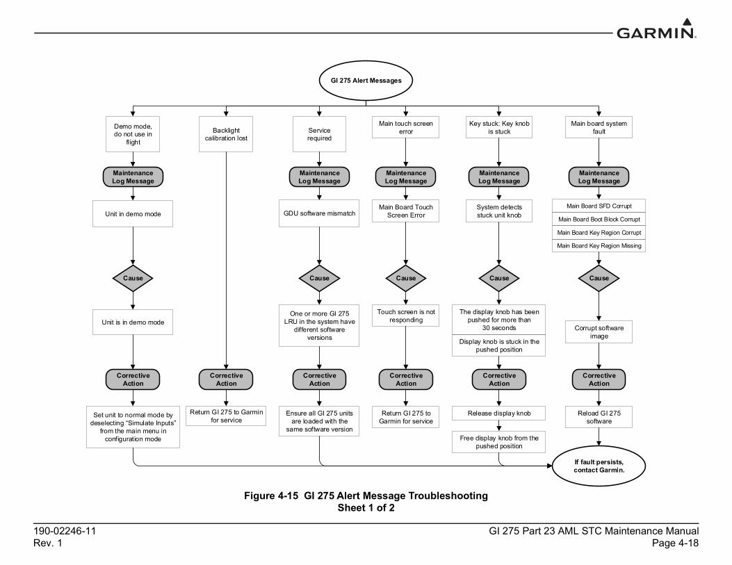
190-02246-11 GI 275 Part 23 AML STC Maintenance ManualRev. 1 Page 4-18
Figure 4-15 GI 275 Alert Message TroubleshootingSheet 1 of 2
GI 275 Alert Messages
If fault persists, contact Garmin.
Demo mode, do not use in
flight
Unit in demo mode
Set unit to normal mode by deselecting “Simulate Inputs”
from the main menu in configuration mode
Backlight calibration lost
Service required
GDU software mismatch
One or more GI 275 LRU in the system have
different software versions
Unit is in demo mode
Return GI 275 to Garmin for service
Ensure all GI 275 units are loaded with the
same software version
Maintenance Log Message
Maintenance Log Message
Cause Cause
Corrective Action
Corrective Action
Corrective Action
Key stuck: Key knob is stuck
Maintenance Log Message
System detects stuck unit knob
Cause
The display knob has been pushed for more than
30 seconds
Display knob is stuck in the pushed position
Corrective Action
Release display knob
Free display knob from the pushed position
Main board system fault
Maintenance Log Message
Main Board SFD Corrupt
Main Board Boot Block Corrupt
Main Board Key Region Corrupt
Main Board Key Region Missing
Cause
Corrupt software image
Corrective Action
Reload GI 275 software
Main touch screen error
Maintenance Log Message
Main Board Touch Screen Error
Cause
Touch screen is not responding
Corrective Action
Return GI 275 to Garmin for service

190-02246-11 GI 275 Part 23 AML STC Maintenance ManualRev. 1 Page 4-19
Figure 4-15 GI 275 Alert Message TroubleshootingSheet 2 of 2
GI 275 Alert Messages Cont’d
If fault persists, contact Garmin.
LCD board system fault
Maintenance Log Message
LCD Board System Error
Cause
Missing LCD software region
LCD Board software failure
Corrective Action
Reload LCD software
Expansion board: Invalid config.
Maintenance Log Message
Expansion board configuration error
Cause
Incorrect expansion board configuration
Corrective Action
Verify expansion board configuration
Internal comm. fault
Cause
Internal hardware failure
Corrective Action
Return GI 275 to Garmin for service
Expansion board system fault
Maintenance Log Message
Expansion Board System Error
Cause
Bad expansion system data
Failed expansion calibration CRC
Corrective Action
Reload expansion board software
Return GI 275 to Garmin for service
Max temperature exceeded
Maintenance Log Message
Expansion Board Temp
Cause
Expansion Board has exceeded temperature
threshold
Corrective Action
Remove GI 275 from extreme temperature
environment
Shut down GI 275 for at least 30 min
LRU replacement error
Maintenance Log Message
LRU replacement error
Cause
Error between GI 275 config module and
installed GI 275
Corrective Action
Verify accuracy of configuration settings on
GI 275
Clear configuration and reconfigure
Replace configuration module

190-02246-11 GI 275 Part 23 AML STC Maintenance ManualRev. 1 Page 4-20
Figure 4-16 Battery Alert Message TroubleshootingSheet 1 of 4
Battery Alert Messages
If fault persists, contact Garmin.
Invalid battery detected
Maintenance Log Message
Battery is not sealed
Cause
GI 275's battery internal
configuration is corrupted
Corrective Action
Replace battery
Battery unavailable: Capacity test
Maintenance Log Message
Battery capacity test failed
Battery capacity test failed
Cause Cause
Battery capacity test failed
Battery capacity test has not been run for
392 days
Corrective Action
Corrective Action
Replace battery Run battery capacity test
Battery unavailable: Communication lost
Maintenance Log Message
Communication was lost with the battery
Cause
Battery not properly seated
Battery is configured but not installed
Corrective Action
Ensure battery is properly installed
Non-Garmin battery detected
Maintenance Log Message
Battery authentication failed
Cause
Non-Garmin battery is installed
Corrective Action
Replace battery with authentic Garmin
battery
Battery operation warning
Maintenance Log Message
Battery charge FET permanent fail fault
Battery discharge FET permanent fail
Battery safety cell overvoltage permanent fail
Cause
Battery has permanently failed
Corrective Action
Replace battery
Battery unavailable: Capacity test
Maintenance Log Message

190-02246-11 GI 275 Part 23 AML STC Maintenance ManualRev. 1 Page 4-21
Figure 4-16 Battery Alert Message TroubleshootingSheet 2 of 4
Battery Alert Messages Cont’d
If fault persists, contact Garmin.
Battery operation warning
Maintenance Log Message
Battery overcurrent during charge protection fault
Cause
Battery circuitry failure
GI 275 charging circuitry failure
Corrective Action
If error self clears, perform battery rundown test, then fully charge battery, ensure
alert does not reoccur
Replace battery
Return GI 275 to Garmin for service
Battery operation warning
Maintenance Log Message
Battery overcurrent during discharge protection fault
Cause
Battery short circuit failure
GI 275 charging circuitry failure
Corrective Action
If error self clears, perform battery rundown test, then fully charge battery, ensure
alert does not reoccur
Replace battery
Return GI 275 to Garmin for service
Battery warning: Charge inhibited
Maintenance Log Message
Battery cell overvoltage
protection fault
Cause
Battery circuitry failure
GI 275 charging circuitry failure
Corrective Action
If error self clears, perform battery rundown test, then fully charge battery, ensure
alert does not reoccur
Replace battery
Return GI 275 to Garmin for service
Battery warning: Charge inhibited
Maintenance Log Message
Battery cell undervoltage
protection fault
Cause
Battery charge was low and left to
discharge further
Corrective Action
Ensure battery warmed to room temperature
environment, attempt charging
Replace battery

190-02246-11 GI 275 Part 23 AML STC Maintenance ManualRev. 1 Page 4-22
Figure 4-16 Battery Alert Message TroubleshootingSheet 3 of 4
Battery Alert Messages Cont’d
If fault persists, contact Garmin.
Battery operation warning
Maintenance Log Message
Battery overtemperature during discharge protection fault
Cause
Battery internal temperature exceeds 80°C during
discharge
Corrective Action
Allow battery to cool, remove exposure to extreme
temperature environment
Replace battery
Battery temperature sensor has failed
Battery operation warning
Maintenance Log Message
Battery undertemperature during discharge protection fault
Cause
Battery internal temperature below -20°C during
discharge
Corrective Action
Allow battery to warm up, remove exposure to extreme
temperature environment
Replace battery
Battery temperature sensor has failed
Battery warning: Charge inhibited
Maintenance Log Message
Battery overtemperature
during charge protection fault
Cause
Corrective Action
Allow battery to cool, remove exposure to extreme
temperature environment
Replace battery
Battery temperature sensor has failed
Battery warning: Charge inhibited
Maintenance Log Message
Battery undertemperature during discharge protection fault
Cause
Battery internal temperature below -20°C during
discharge
Corrective Action
Allow battery to warm up, remove exposure to extreme
temperature environment
Replace battery
Battery temperature sensor has failed
Battery internal temperature exceeds 80°C during
discharge
Battery operation warning
Maintenance Log Message
Battery overload during discharge protection fault
Cause
Battery current overdraw
Partial short in battery circuitry
Partial short in GI 275 circuitry
External LRU excessive current draw with GI 275 overcurrent
circuitry failure
Replace battery
Corrective Action
Return GI 275 to Garmin for service
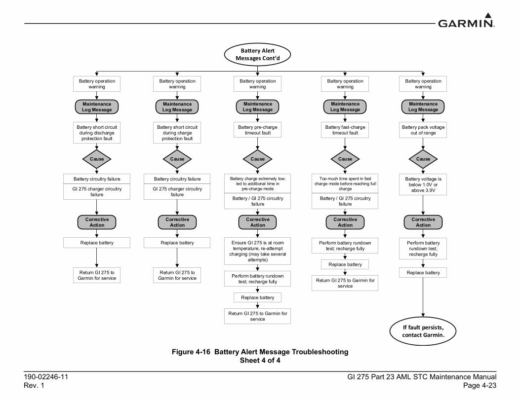
190-02246-11 GI 275 Part 23 AML STC Maintenance ManualRev. 1 Page 4-23
Figure 4-16 Battery Alert Message TroubleshootingSheet 4 of 4
Battery Alert Messages Cont’d
If fault persists, contact Garmin.
Battery operation warning
Maintenance Log Message
Battery short circuit during discharge protection fault
Cause
Battery circuitry failure
Corrective Action
Replace battery
Return GI 275 to Garmin for service
GI 275 charger circuitry failure
Battery operation warning
Maintenance Log Message
Battery short circuit during charge protection fault
Cause
Battery circuitry failure
Corrective Action
Replace battery
Return GI 275 to Garmin for service
GI 275 charger circuitry failure
Battery operation warning
Maintenance Log Message
Battery pre-charge timeout fault
Cause
Battery charge extremely low; led to additional time in
pre-charge mode
Battery / GI 275 circuitry failure
Corrective Action
Ensure GI 275 is at room temperature, re-attempt
charging (may take several attempts)
Perform battery rundown test; recharge fully
Replace battery
Return GI 275 to Garmin for service
Battery operation warning
Maintenance Log Message
Battery fast-charge timeout fault
Cause
Too much time spent in fast charge mode before reaching full
charge
Battery / GI 275 circuitry failure
Corrective Action
Perform battery rundown test; recharge fully
Replace battery
Return GI 275 to Garmin for service
Battery operation warning
Maintenance Log Message
Battery pack voltage out of range
Cause
Battery voltage is below 1.0V or above 3.9V
Corrective Action
Perform battery rundown test; recharge fully
Replace battery

190-02246-11 GI 275 Part 23 AML STC Maintenance ManualRev. 1 Page 4-24
Figure 4-17 AHRS Alert Message Troubleshooting
AHRS Fault Messages
If fault persists, contact Garmin.
AHRS <1/2/3> MISSING
-or-AHRS MISSING
Cause
Multiple AHRS are configured in the system and the
reported AHRS is not detected
Corrective Action
Ensure the missing AHRS is powered
Ensure the missing AHRS configuration
is correct
Verify wiring is correct
AHRS <1/2/3> MISCOMPARE
-or- AHRSMISCOMPARE
Cause
Multiple AHRS are configured, a reported AHRS heading
difference of 6 degrees or more is detected
Maintenance Log Message
Maintenance Log Message
AHRS <1/2/3> does not match other senosrs
All AHRS sensors do not match
AHRS <1/2/3> data is missing and cannot be
compared
Not enough AHRS sensors to perform a comparison
Multiple AHRS are configured, a reported AHRS pitch or roll of 5 degrees or more is detected
Corrective Action
Determine if pitch, roll or heading is out
of tolerance
Heading out of tolerance: perform magnetic calibration
on all configured heading sources
AHRS <1/2/3>: Magnetic model
outdated
Cause
Maintenance Log Message
Corrective Action
Pitch or roll out of tolerance: perform
pitch-roll offset calibration on all
configured sources
AHRS <1/2/3> Magnetic Model
out of date
Magnetic model is out of date
Update the IGRF Magnetic Field
Model
Cause
Maintenance Log Message
Corrective Action
AHRS <1/2/3> not receiving GPS
aiding
AHRS <1/2/3> not receiving GPS
aiding
Not receiving GPS data from a
configured GPS source
Verify GPS configurations
Verify GPS antenna has a clear view of the sky and
GPS source has a valid fix
Verify connections and wiring
AHRS <1/2/3> reports service
required
Cause
Corrective Action
Service required
Cause
Maintenance Log Message
Corrective Action
<AHRS> configuration does not match what the
unit expected
AHRS LRU is not configured correctly
Verify AHRS configuration
settings
Bad AHRS calibration
No data from ADC
Ensure ADC is powered on
Perform AHRS calibration
Verify connections and wiring
Magnetic variance inaccurate
Maintenance Log Message
ADB and IOP packet magnetic variances differ
Cause
Aviation database out-of-date on
GI 275 / Navigator
Corrective Action
Ensure aviation database is up-to-date on GI 275 and configured navigator
Magnetic variance unavailable
Maintenance Log Message
ADB is unavailable for magnetic
variance
Cause
Aviation database is missing
Navigator / GPS source unavailable
Corrective Action
Ensure aviation database is loaded
and up-to-date
Verify GPS source online

190-02246-11 GI 275 Part 23 AML STC Maintenance ManualRev. 1 Page 4-25
Figure 4-18 ADC Alert Message Troubleshooting
ADC Fault Messages
If fault persists, contact Garmin.
ADC <1/2/3> MISSING
-or-ADC MISSING
Cause
Multiple ADCs are configured in the system and the
reported ADC is not detected
Corrective Action
Ensure the missing ADC is powered
Ensure the missing ADC configuration
is correct
Verify wiring is correct
ADC <1/2/3> MISCOMPARE
-or- ADCMISCOMPARE
Cause
Multiple ADCs are configured, a reported ADC pressure altitude difference of 200ft or more is
detected
Maintenance Log Message
Maintenance Log Message
ADC <1/2/3> does not match other senosrs
All ADC sensors do not match
ADC <1/2/3> data is missing and cannot be
compared
Not enough ADC sensors to perform a comparison
Multiple ADCs are configured, a reported ADC airspeed
difference of 7kts or more is detected
Corrective Action
Ensure the altitude and airspeed units of measure are the
same for all configured ADCs
Ensure there are no leaks in the pitot
static system
ADC <1/2/3> reports service
required
Cause
Corrective Action
ADC <1/2/3> reports service
required
Maintenance Log Message
ADC <1/2/3> reports
configuration error
Cause
ADC is reporting a configuration error
Corrective Action
Verify ADC configuration
settings
Service required
Cause
Maintenance Log Message
Corrective Action
<AHRS> configuration does not match what the
unit expected
AHRS LRU is not configured correctly
Verify AHRS configuration
settings
ADC internal calibration mismatch
Perform ADC calibration procedure
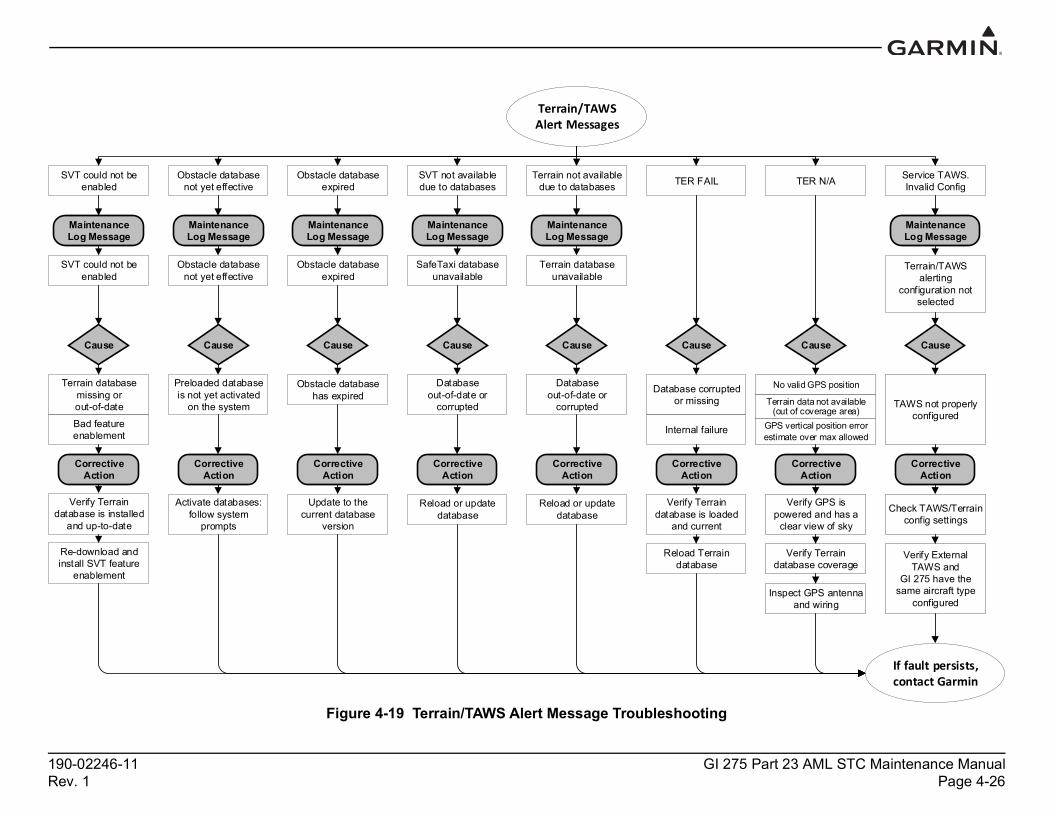
190-02246-11 GI 275 Part 23 AML STC Maintenance ManualRev. 1 Page 4-26
Figure 4-19 Terrain/TAWS Alert Message Troubleshooting
Terrain/TAWS Alert Messages
TAWS not properly configured
Check TAWS/Terrain config settings
Verify External TAWS and
GI 275 have the same aircraft type
configured
If fault persists, contact Garmin
No valid GPS position
Verify GPS is powered and has a
clear view of sky
Verify Terrain database coverage
Inspect GPS antenna and wiring
GPS vertical position error estimate over max allowed
Terrain data not available (out of coverage area)
Cause Cause Cause
Maintenance Log Message
TER FAIL TER N/A
Corrective Action
Corrective Action
Corrective Action
Database corrupted or missing
Internal failure
Service TAWS.Invalid Config
Terrain/TAWS alerting
configuration not selected
Verify Terrain database is loaded
and current
Reload Terrain database
Terrain not available due to databases
Maintenance Log Message
Terrain database unavailable
Cause
Database out-of-date or
corrupted
Corrective Action
Reload or update database
SVT not available due to databases
Maintenance Log Message
SafeTaxi database unavailable
Cause
Databaseout-of-date or
corrupted
Corrective Action
Reload or update database
Obstacle database expired
Obstacle database not yet effective
Maintenance Log Message
Obstacle database expired
Cause
Obstacle database has expired
Corrective Action
Update to the current database
version
Maintenance Log Message
Obstacle database not yet effective
Cause
Preloaded database is not yet activated
on the system
Corrective Action
Activate databases: follow system
prompts
SVT could not be enabled
Maintenance Log Message
SVT could not be enabled
Cause
Terrain database missing or out-of-date
Corrective Action
Bad feature enablement
Verify Terrain database is installed
and up-to-date
Re-download and install SVT feature
enablement

190-02246-11 GI 275 Part 23 AML STC Maintenance ManualRev. 1 Page 4-27
Figure 4-20 Traffic Alert Message TroubleshootingSheet 1 of 2
ADS‐B Traffic Alert Messages
If fault persists, contact Garmin
ADS traffic function inoperative
Corrective Action
TAS/TCAS function inoperative
ADS-B In traffic source mismatch
Maintenance Log Message
ADS-B In traffic source does not
match configuration
Cause
ADS-B traffic format does not match the
external LRU configuration
Corrective Action
Verify configuration
ADS traffic alerting inoperative
1090ES traffic receiver fault
Maintenance Log Message
ADS-B LRU reports CSA/TSAA failure
Cause
ADS-B In external LRU traffic receiver
has failed
Corrective Action
Refer to ADS-B LRU manual for troubleshooting
Maintenance Log Message
ADS-B LRU reports 1090ES traffic receiver fault
Corrective Action
Refer to ADS-B LRU manual for troubleshooting
Maintenance Log Message
ADS-B LRU reports ADS-B Traffic In
has failed
Troubleshoot device in accordance with
ADS-B LRU maintenance
manual
Maintenance Log Message
ADS-B LRU reports TAS/TCAS
inoperative or connection lost
Corrective Action
Troubleshoot device in accordance with
ADS-B LRU maintenance
manual
UAT fault
Maintenance Log Message
UAT LRU reports low WAAS battery
fault
Corrective Action
Troubleshoot device in accordance with
UAT LRU maintenance
manual
UAT traffic/data receiver fault
Maintenance Log Message
ADS-B LRU reports UAT traffic/data
receiver fault
Corrective Action
Troubleshoot device in accordance with
ADS-B LRU maintenance
manual
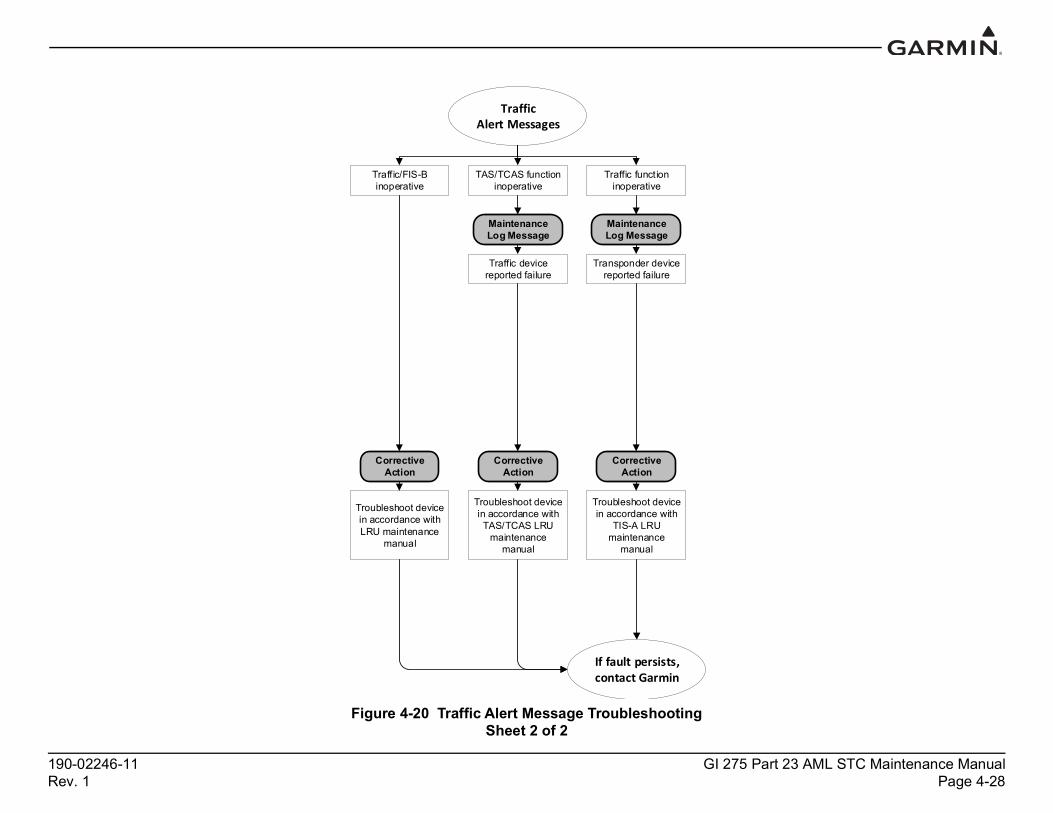
190-02246-11 GI 275 Part 23 AML STC Maintenance ManualRev. 1 Page 4-28
Figure 4-20 Traffic Alert Message TroubleshootingSheet 2 of 2
Traffic Alert Messages
If fault persists, contact Garmin
Traffic function inoperative
Corrective Action
Troubleshoot device in accordance with
TIS-A LRU maintenance
manual
TAS/TCAS function inoperative
Maintenance Log Message
Traffic device reported failure
Corrective Action
Troubleshoot device in accordance with TAS/TCAS LRU
maintenance manual
Maintenance Log Message
Transponder device reported failure
Traffic/FIS-B inoperative
Corrective Action
Troubleshoot device in accordance with LRU maintenance
manual
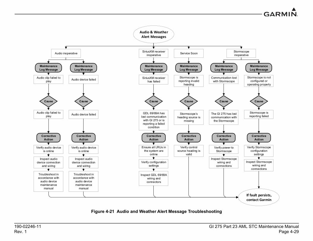
190-02246-11 GI 275 Part 23 AML STC Maintenance ManualRev. 1 Page 4-29
Figure 4-21 Audio and Weather Alert Message Troubleshooting
Audio & Weather Alert Messages
If fault persists, contact Garmin
Cause
SiriusXM receiver inoperative
Corrective Action
GDL 69/69A has lost communication
with GI 275 or is reporting a failed
condition
Ensure all LRUs in the system are
online
Verify configuration settings
Maintenance Log Message
Stormscope is not configured or
operating properly
Cause
Stormscope is reporting failed
Corrective Action
Verify Stormscope configuration
settings
Stormscope inoperative
Maintenance Log Message
Communication lost with Stormscope
Cause
The GI 275 has lost communication with
the Stormscope
Corrective Action
Verify power to Stormscope
Audio inoperative
Maintenance Log Message
Audio device failed
Cause
Audio device failed
Corrective Action
Maintenance Log Message
Audio clip failed to play
Cause
Audio clip failed to play
Corrective Action
Verify audio device is online
Inspect audio device connection
and wiring
Troubleshoot in accordance with
audio device maintenance
manual
Verify audio device is online
Inspect audio device connection
and wiring
Troubleshoot in accordance with
audio device maintenance
manual
Inspect Stormscope wiring and
connectionsInspect Stormscope
wiring and connections
Maintenance Log Message
SiriusXM receiver has failed
Inspect GDL 69/69A wiring and connectors
Service Soon
Maintenance Log Message
Stormscope is reporting invalid
heading
Cause
Stormscope’s heading source is
missing
Corrective Action
Verify control source heading is
valid

190-02246-11 GI 275 Part 23 AML STC Maintenance ManualRev. 1 Page 4-30
Figure 4-22 NAV Alert Message Troubleshooting
NAV/GPS Alert Messages
If fault persists, contact Garmin.
NAV <1/2> inoperative
Maintenance Log Message
NAV <1/2> interface/unit failed. Check NAV unit or
wiring.
Cause
NAV source has lost communication
NAV source is reporting failed
Corrective Action
Corrective Action
Verify NAV source is on and not
reporting failed
Troubleshoot in accordance with
NAV unit maintenance
manual
Verify configuration settings
Inspect NAV wiring and connections
Verify configuration settings
Inspect NAV wiring and connections
Navigation database mismatch
Maintenance Log Message
Navigation database mismatch
Cause
Multiple GI 275 units have different NAV
database expirations
Corrective Action
Update databases across all units to
the same date
Navigation database not yet effective
Maintenance Log Message
Navigation database not yet
effective
Cause
Preloaded database is not activated on
the system
Corrective Action
Activate databases: Follow system
prompts
Navigation database expired
Maintenance Log Message
Navigation database expired
Cause
Navigation database has
expired
Corrective Action
Update to the current database
version
GPS <1/2> inoperative
Maintenance Log Message
GPS <1/2> interface failed
Cause
GPS source has lost communication
GPS source is reporting failed
Corrective Action
Verify GPS source is ON and has a clear view of the sky
Verify configuration settings
Inspect GPS antenna, wiring and connections

190-02246-11 GI 275 Part 23 AML STC Maintenance ManualRev. 1 Page 4-31
Figure 4-23 Autopilot Alert Message Troubleshooting
Autopilot Fault Messages
If fault persists, contact Garmin.
Autopilot fault
Maintenance Log Message
Autopilot reference monitor
Cause
Configured autopilot reference voltage does not match actual voltage
Corrective Action
Verify GI 275 reference voltage
matches the required autopilot reference voltage
Power fault
Cause
GI 275 internal autopilot voltage output is below
threshold voltage
Corrective Action
Ensure GI 275 is not on backup battery power
Clear autopilot configuration settings and reconfigure
GMC ESP inoperative
Cause
Refer to Section 5.2 of the GFC 600
AFCS Part 23 AML STC Maintenance
Manual
Maintenance Log Message
GMC electronic stability protection
failed
Corrective Action
Refer to Section 5.2 of the GFC 600
AFCS Part 23 AML STC Maintenance
Manual
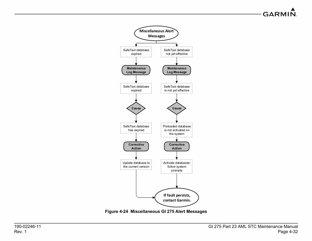
190-02246-11 GI 275 Part 23 AML STC Maintenance ManualRev. 1 Page 4-32
Figure 4-24 Miscellaneous GI 275 Alert Messages
Miscellaneous Alert Messages
If fault persists, contact Garmin.
SafeTaxi database expired
Maintenance Log Message
SafeTaxi database expired
Cause
SafeTaxi database has expired
Corrective Action
Update database to the current version
SafeTaxi database not yet effective
Maintenance Log Message
SafeTaxi database is not yet effective
Cause
Preloaded database is not activated on
the system
Corrective Action
Activate databases: follow system
prompts

190-02246-11 GI 275 Part 23 AML STC Maintenance ManualRev. 1 Page 4-33
Figure 4-25 External LRU Alert Message Troubleshooting
External LRU Alert Messages
If fault persists, contact Garmin.
Crosstalk error
Maintenance Log Message
Crosstalk Error
Cause
Interfacing LRU is not powered
Interfacing LRU not configured properly
Interfacing LRU does not have compatible software version
Incorrect wiring
Corrective Action
Verify power to unit
Verify configuration settings
Verify proper software version
Verify wiring
<External LRU> service required
System ID set on GI 275 is different from that on
the external LRU
Cause
Corrective Action
Ensure configured System ID on GI 275 and external LRU are
the same
Service required
Maintenance Log Message
GEA <1/2/3/4> did not accept configuration
Cause
GEA configuration settings were not
accepted
Corrective Action
Verify GEA configuration
settings
Service soon
Maintenance Log Message
GTX 345 reports config module needs service
Corrective Action
Troubleshoot in accordance with the
GTX 3X5 maintenance
manual
Service soon
Maintenance Log Message
System configuration module has failed or is missing
Cause
Configuration module not installed correctly
Configuration module has failed
Corrective Action
Verify configuration module wiring
Replace configuration
module

190-02246-11 GI 275 Part 23 AML STC Maintenance ManualRev. 1 Page 5-1
5 EQUIPMENT MAINTENANCE AND CHECKOUT PROCEDURES
5.1 GI 275..............................................................................................................................................5-35.1.1 GI 275 Removal .......................................................................................................................5-35.1.2 GI 275 Configuration Module Replacement ............................................................................5-45.1.3 GI 275 Re-installation ..............................................................................................................5-5
5.2 EIS Annunciator ..............................................................................................................................5-65.2.1 EIS Annunciator Removal .......................................................................................................5-65.2.2 EIS Annunciator Re-installation ..............................................................................................5-65.2.3 Separate EIS Annunciator Removal.........................................................................................5-75.2.4 Separate EIS Annunciator Re-installation................................................................................5-7
5.3 GEA 24............................................................................................................................................5-85.3.1 GEA 24 Removal .....................................................................................................................5-95.3.2 GEA 24 Re-installation ............................................................................................................5-95.3.3 GEA 24 Checkout ....................................................................................................................5-9
5.4 GEA 110........................................................................................................................................5-105.4.1 GEA 110 Removal .................................................................................................................5-125.4.2 GEA 110 Re-installation ........................................................................................................5-125.4.3 GEA 110 Checkout ................................................................................................................5-12
5.5 Backup Battery ..............................................................................................................................5-135.5.1 Backup Battery Removal .......................................................................................................5-135.5.2 Backup Battery Re-installation ..............................................................................................5-135.5.3 Backup Battery Checkout.......................................................................................................5-13
5.6 GSB 15 ..........................................................................................................................................5-145.6.1 GSB 15 Removal....................................................................................................................5-175.6.2 GSB 15 Re-installation...........................................................................................................5-17
5.7 GMU 11.........................................................................................................................................5-185.7.1 GMU 11 Removal ..................................................................................................................5-195.7.2 GMU 11 Re-installation .........................................................................................................5-195.7.3 GMU 11 Checkout .................................................................................................................5-19
5.8 GMU 44B ......................................................................................................................................5-205.8.1 GMU 44B Removal ...............................................................................................................5-215.8.2 GMU 44B Re-installation ......................................................................................................5-215.8.3 GMU 44B Checkout...............................................................................................................5-21
5.9 GTP 59...........................................................................................................................................5-225.9.1 GTP 59 Removal ....................................................................................................................5-235.9.2 GTP 59 Re-installation...........................................................................................................5-235.9.3 GTP 59 Checkout ...................................................................................................................5-23
5.10 VFR GPS Antenna ........................................................................................................................5-245.10.1 VFR GPS Antenna Removal..................................................................................................5-255.10.2 VFR GPS Antenna Re-installation.........................................................................................5-255.10.3 VFR GPS Antenna Checkout .................................................................................................5-25
5.11 EIS Sensors....................................................................................................................................5-265.11.1 Carburetor/Induction Air Temperature ..................................................................................5-275.11.2 Oil Temperature Sensor .........................................................................................................5-285.11.3 Pressure Sensors .....................................................................................................................5-295.11.4 Fuel Flow................................................................................................................................5-325.11.5 Engine RPM ...........................................................................................................................5-33
5.12 Calibration .....................................................................................................................................5-34

190-02246-11 GI 275 Part 23 AML STC Maintenance ManualRev. 1 Page 5-2
5.12.1 Attitude/Heading ....................................................................................................................5-345.12.2 Autopilot Calibration..............................................................................................................5-345.12.3 Analog NAV Calibration .......................................................................................................5-345.12.4 Fuel Level Calibration............................................................................................................5-345.12.5 Backup Battery Check............................................................................................................5-34
5.13 Uploading Software.......................................................................................................................5-365.14 System Checks...............................................................................................................................5-37
5.14.1 Configuration Ground Check .................................................................................................5-375.14.2 Pitot-Static and Airspeed Tape Settings Checks ....................................................................5-38
This section provides the procedures to remove, replace, and re-install required and optional LRUs that are part of the GI 275 system. Refer to Section 4.2 for the definition of connectors and pin functions for GI 275 system LRUs. Before performing any maintenance on the GI 275 system, all information in Appendix A must be filled out. It is highly recommended to save the system configuration to a USB drive and print the configuration log before replacing any system LRUs.
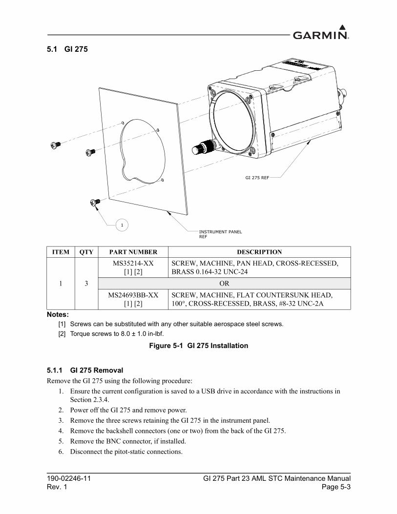
190-02246-11 GI 275 Part 23 AML STC Maintenance ManualRev. 1 Page 5-3
5.1 GI 275
Notes:[1] Screws can be substituted with any other suitable aerospace steel screws.[2] Torque screws to 8.0 ± 1.0 in-lbf.
Figure 5-1 GI 275 Installation
5.1.1 GI 275 RemovalRemove the GI 275 using the following procedure:
1. Ensure the current configuration is saved to a USB drive in accordance with the instructions in Section 2.3.4.
2. Power off the GI 275 and remove power.3. Remove the three screws retaining the GI 275 in the instrument panel.4. Remove the backshell connectors (one or two) from the back of the GI 275.5. Remove the BNC connector, if installed.6. Disconnect the pitot-static connections.
ITEM QTY PART NUMBER DESCRIPTION
1 3
MS35214-XX [1] [2]
SCREW, MACHINE, PAN HEAD, CROSS-RECESSED, BRASS 0.164-32 UNC-24
ORMS24693BB-XX
[1] [2]SCREW, MACHINE, FLAT COUNTERSUNK HEAD, 100°, CROSS-RECESSED, BRASS, #8-32 UNC-2A
1INSTRUMENT PANELREF
GI 275 REF

190-02246-11 GI 275 Part 23 AML STC Maintenance ManualRev. 1 Page 5-4
5.1.2 GI 275 Configuration Module ReplacementTo replace a GI 275 configuration module, perform the following procedure. All item numbers in this procedure refer to Figure 5-2. If replacing the configuration module on the Master display, the System ID will change and must be updated on the associated flyGarmin.com account to re-enable purchased feature enablements on the system.
1. Save the current configuration in accordance with the instructions in Section 2.3.4.2. Remove the GI 275 in accordance with Section 5.1.1.3. Remove the backshell cover (7) from connector J2751 by removing the two screws (8).4. Remove the screw (10) securing the configuration module (1) to the backshell (6).5. Lift the configuration module (1) out of the backshell (6) and disconnect the wiring harness (3)
from the module.6. Inspect the wiring harness (3) and connector pins (4) for damage, loose wiring, or corrosion.
Replace all deficient components if any of these conditions are found.7. Connect the harness to the new configuration module.8. Install the new configuration module in the connector backshell (6) and re-install the cover (7).9. Re-install the GI 275 in accordance with Section 5.1.3.10. If desired, import the saved configuration into the new configuration module using the procedure
in Section 2.3.3.
Figure 5-2 Configuration Module Installation

190-02246-11 GI 275 Part 23 AML STC Maintenance ManualRev. 1 Page 5-5
5.1.3 GI 275 Re-installationTo re-install the GI 275, perform the following procedure:
1. Place the GI 275 into the instrument panel cutout.2. Install the three screws. Torque to specifications in Figure 5-1.3. Connect the pitot-static connections.4. Connect the wiring connector(s) and any installed antenna wires to the back of the GI 275 and
tighten the retaining screws.5. Perform the Configuration mode ground checks in Section 5.14.1.

190-02246-11 GI 275 Part 23 AML STC Maintenance ManualRev. 1 Page 5-6
5.2 EIS Annunciator5.2.1 EIS Annunciator RemovalThe Applied Avionics EIS caution and warning annunciator can be removed using the following procedure:
1. Using an Aerospace Optics cap extraction tool (P/N 17-150), locate the two extraction slots positioned on either side of the pushbutton cap.
2. Insert the tool into the extraction slots and pull the cap out from the module.
NOTEThe cap will rotate 90° on two hinged slide retainer pins to allow access to the module mounting screws.
3. Loosen the two small flat head module mounting screws located behind the pushbutton cap until the module can be removed from the housing.
4. Insert an Aerospace Optics connector extraction tool (P/N 18-234) into the slots at the top and bottom of the electrical connector.
5. Push to release the snap tabs in the switch housing and gently pull the connector out of the module.
Figure 5-3 EIS Caution and Warning Annunciator Installation
5.2.2 EIS Annunciator Re-installationRe-installation of the annunciator is accomplished using the following procedure:
1. Orient the keyed electrical connector to the module and press together until locked.2. Orient the annunciator for proper viewing and gently slide the module into the housing until
seated.3. Tighten the mounting screws until the module is fully seated in the housing.4. Rotate the cap back into position on the module and gently press until secured.

190-02246-11 GI 275 Part 23 AML STC Maintenance ManualRev. 1 Page 5-7
5.2.3 Separate EIS Annunciator RemovalThe Mil-Spec EIS annunciators can be removed using the following procedure:
1. Remove the lens holder from the indicator.2. Remove the lamp from the lens holder.3. Remove the MS25041 assembly.
Figure 5-4 Separate EIS Annunciator Installation
5.2.4 Separate EIS Annunciator Re-installationRe-installation of the annunciators is accomplished using the following procedure:
1. Insert the MS25041 assembly without lens holder from the forward side of the panel and secure.2. Install lamp on the lens holder.3. Install and secure lens holder on the indicator.
ITEM OTY PART NUMBER DESCRIPTION
1
1 MS25041-2-327 ANNUNCIATOR, RED, PRESS TO FIT FOR 28V AIRCRAFT2
3
1 MS25041-2-330 ANNUNCIATOR, RED, PRESS TO FIT FOR 14V AIRCRAFT 4
1 MS25041-4-327 ANNUNCIATOR, YELLOW, PRESS TO FIT FOR 28V
AIRCRAFT
1 MS25041-4-330 ANNUNCIATOR, YELLOW, PRESS TO FIT FOR 14V
AIRCRAFT

190-02246-11 GI 275 Part 23 AML STC Maintenance ManualRev. 1 Page 5-8
5.3 GEA 24
Notes:[1] Screws can be substituted by any other suitable aerospace steel screws.[2] Torque 0.190-32 UNF-2A screws 13.5 ± 1.0 in-lbf.[3] Nut can be substituted by any suitable aerospace steel self-locking nuts or nutplates.
Figure 5-5 Example GEA 24 Installation
ITEM QTY PART NUMBER DESCRIPTION
1 1 011-02848-01 GEA 24 REMOTE MOUNTED ENGINE INTERFACE UNIT
2 4 MS35207-XX [1] [2]
SCREW, MACHINE, PAN HEAD, CROSS-RECESSED, CARBON STEEL, CADMIUM PLATED, #10-32 UNF-2A
3 8 NAS1149F0363P WASHER
4 4 MS21044N3 [3] NUT SELF-LOCKING, HEXAGON REGULAR HEIGHT, 250°F, CADMIUM PLATED, STEEL, #10-32
190-02246-11 GI 275 Part 23 AML STC Maintenance ManualRev. 1 Page 5-9
5.3.1 GEA 24 RemovalTo remove the GEA 24, perform the following procedure:
1. Remove power from the GEA 24. 2. Disconnect the four electrical connectors.3. Remove the four screws.
5.3.2 GEA 24 Re-installationTo re-install the GEA 24, perform the removal procedures in reverse.
If the GEA 24 was replaced, the sensor configurations must be loaded to the new unit using the following procedure:
1. Power on the GI 275 that is directly interfaced to the GEA 24 into Configuration mode.2. Insert the USB drive containing the saved configuration into the USB dongle or GSB 15. A USB
icon should appear in the bottom-left of the display once the GI 275 has recognized the device. If the icon doesn’t appear after 1 minute, remove the drive and re-insert it.
3. Touch the SW/Config button, then the Config Options button.4. Touch the Import Configuration button.5. Touch the Select Files button and select the appropriate aircraft configuration file.6. Touch the Select Configuration button.7. Touch the EIS Sensor Config button to select it. Touch the Back button.8. Touch the Import Config button and then the Start button.9. A restart is required to complete import. Touch the Restart Now button.
5.3.3 GEA 24 CheckoutPerform the Configuration Mode Ground Checks described in Section 5.14.1. If the GEA 24 does not pass the checks in this step, reload the sensor configurations using the procedure in Section 5.3.2 and perform the checkout procedure again.
If the GEA 24 was replaced or did not initially pass the checkout procedure, perform the EIS Ground Checks described in Section 6 of GI 275 Part 23 AML STC Installation Manual (P/N 190-02246-10) or GI 275 STC EIS & MFD Installation Manual (P/N 190-02246-14).

190-02246-11 GI 275 Part 23 AML STC Maintenance ManualRev. 1 Page 5-10
5.4 GEA 110
Figure 5-6 GEA 110 Installation (Mounted Directly to Airframe Example)

190-02246-11 GI 275 Part 23 AML STC Maintenance ManualRev. 1 Page 5-11
Figure 5-7 GEA 110 Installation (Mounted on a Tray Example)

190-02246-11 GI 275 Part 23 AML STC Maintenance ManualRev. 1 Page 5-12
5.4.1 GEA 110 RemovalTo remove the GEA 110, perform the following procedure:
1. Remove power from the GEA 110. 2. Disconnect the two electrical connectors.3. If the unit is mounted on a tray, as shown in Figure 5-7, pull out on the mounting knob and turn
counterclockwise to loosen it enough to rotate the arm down and away from the unit.4. If the unit is mounted to the airframe using screws, as shown in Figure 5-6, loosen the four screws
securing the unit to the airframe.
5.4.2 GEA 110 Re-installationTo re-install the GEA 110, perform the removal procedures in reverse. If the unit is mounted to the airframe, torque the screws to the specification in Figure 5-6. For units that are mounted in a mounting tray, tighten the mounting screw by hand until the unit is secure.
If the GEA 110 was replaced, the sensor configurations must be loaded to the new unit using the following procedure:
1. Power on the GI 275 that is directly interfaced to the GEA 110 into Configuration mode.2. Insert the USB drive containing the saved configuration into the USB dongle or GSB 15. A USB
icon should appear in the bottom-left of the display once the GI 275 has recognized the device. If the icon doesn’t appear after 1 minute, remove the drive and re-insert it.
3. Touch the SW/Config button, then the Config Options button.4. Touch the Import Configuration button.5. Touch the Select Files button and select the appropriate aircraft configuration file.6. Touch the Select Configuration button.7. Touch the EIS Sensor Config button to select it. Touch the Back button.8. Touch the Import Config button and then the Start button.9. A restart is required to complete import. Touch the Restart Now button.
5.4.3 GEA 110 CheckoutPerform the Configuration Mode Ground Checks described in Section 5.14.1. If the GEA 110 does not pass the checks in this step, reload the sensor configurations using the procedure in Section 5.4.2 and perform the checkout procedure again.
If the GEA 110 was replaced or did not initially pass the checkout procedure, perform the EIS Ground Checks described in Section 6 of GI 275 Part 23 AML STC Installation Manual (P/N 190-02246-10).

190-02246-11 GI 275 Part 23 AML STC Maintenance ManualRev. 1 Page 5-13
5.5 Backup Battery5.5.1 Backup Battery Removal
1. Remove the GI 275 in accordance with Section 5.1.1.2. Remove the four screws securing the battery access panel to the top of the GI 275 and remove the
panel.3. Remove the battery by pulling the battery pack straight up until it is unseated from the connector.
5.5.2 Backup Battery Re-installation1. Lower the battery with the rubber end caps onto the GI 275 connector. Ensure proper alignment
and push down to seat the connector.2. The unit will automatically power on. Power off the unit.3. Re-install the battery access panel and the four panel screws. Torque screws to 8 ± 1 in-lbf.4. Re-install the GI 275 in accordance with Section 5.1.3.
5.5.3 Backup Battery Checkout1. Perform an LRU Status Check as described in Section 5.14.1.1 to ensure the battery is connected
properly. 2. If the battery was replaced, perform the Backup Battery Check as described in Section 5.12.5.
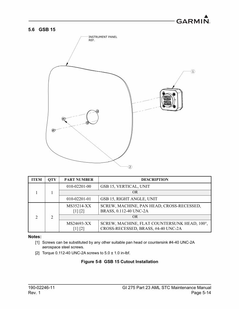
190-02246-11 GI 275 Part 23 AML STC Maintenance ManualRev. 1 Page 5-14
5.6 GSB 15
Notes:[1] Screws can be substituted by any other suitable pan head or countersink #4-40 UNC-2A
aerospace steel screws.[2] Torque 0.112-40 UNC-2A screws to 5.0 ± 1.0 in-lbf.
Figure 5-8 GSB 15 Cutout Installation
ITEM QTY PART NUMBER DESCRIPTION
1 1010-02201-00 GSB 15, VERTICAL, UNIT
OR
010-02201-01 GSB 15, RIGHT ANGLE, UNIT
2 2
MS35214-XX[1] [2]
SCREW, MACHINE, PAN HEAD, CROSS-RECESSED, BRASS, 0.112-40 UNC-2A
OR
MS24693-XX[1] [2]
SCREW, MACHINE, FLAT COUNTERSUNK HEAD, 100°, CROSS-RECESSED, BRASS, #4-40 UNC-2A
INSTRUMENT PANELREF.
1
2

190-02246-11 GI 275 Part 23 AML STC Maintenance ManualRev. 1 Page 5-15
Notes:[1] Screws can be substituted by any other suitable aerospace steel screws.[2] Torque 0.112-40 UNC-2A screws to 5.0 ± 1.0 in-lbf.[3] Torque 0.138-32 UNC-2A screws to 8.0 ± 1.0 in-lbf.
Figure 5-9 GSB 15 Installation with Mounting Kit (2.25-Inch Cutout)
ITEM QTY PART NUMBER DESCRIPTION
1 1010-02201-00 GSB 15, VERTICAL, UNIT
OR
010-02201-01 GSB 15, RIGHT ANGLE, UNIT2 1 011-05043-00 SUB-ASSY, MOUNTING KIT, 2.25”, GSB 15
3 2 MS24693BB-XX [1] [2]
SCREW, MACHINE, FLAT COUNTERSUNK HEAD, 100°P, CROSS-RECESSED, BRASS, #4-40 UNC-2A
4 4
MS35214-XX [1] [3] SCREW, MACHINE, PAN HEAD, CROSS-RECESSED, BRASS, 0.138-32 UNC-2A
OR
MS24693BB-XX [1] [3]
SCREW, MACHINE, FLAT COUNTERSUNK HEAD, 100°P, CROSS-RECESSED, BRASS, #6-32 UNC 2-A
3
REF.INSTRUMENT PANEL
2
1
4

190-02246-11 GI 275 Part 23 AML STC Maintenance ManualRev. 1 Page 5-16
Notes:[1] Screws can be substituted by any other suitable aerospace steel screws.[2] Torque 0.112-40 UNC-2A screws to 5.0 ± 1.0 in-lbf.[3] Torque 0.138-32 UNC-2A screws to 8.0 ± 1.0 in-lbf.
Figure 5-10 GSB 15 Installation with Mounting Kit (3.125-Inch Cutout)
ITEM QTY PART NUMBER DESCRIPTION
1 1010-02201-00 GSB 15, VERTICAL, UNIT
OR
010-02201-01 GSB 15, RIGHT ANGLE, UNIT2 1 011-05043-01 SUB-ASSY, MOUNTING KIT, 3.125”, GSB 15
3 2 MS24693BB-XX [1] [2]
SCREW, MACHINE, FLAT COUNTERSUNK HEAD, 100°, CROSS-RECESSED, BRASS, #4-40 UNC-2A
4 4
MS35214-XX [1] [3] SCREW, MACHINE, PAN HEAD, CROSS-RECESSED BRASS, 0.138-32 UNC-2A
OR
MS24693BB-XX [1] [3]
SCREW, MACHINE, FLAT COUNTERSUNK HEAD, 100°P, CROSS-RECESSED, #6-32 UNC-2A
2
3
1
REF.INSTRUMENT PANEL
4
190-02246-11 GI 275 Part 23 AML STC Maintenance ManualRev. 1 Page 5-17
5.6.1 GSB 15 RemovalTo remove the GSB 15, perform the following procedure:
1. Disconnect the GSB 15 connector.2. If installed with a mounting kit, remove the four screws securing the mounting plate to the
instrument panel (refer to Figure 5-9 or Figure 5-10).3. Remove the two screws securing the GSB 15 to the instrument panel/mounting plate/mounting
surface.
5.6.2 GSB 15 Re-installationTo re-install the GSB 15, perform the removal procedure in reverse. Torque all screws in accordance with Figure 5-8, Figure 5-9, or Figure 5-10.

190-02246-11 GI 275 Part 23 AML STC Maintenance ManualRev. 1 Page 5-18
5.7 GMU 11
Notes:[1] MS5195 screws can be substituted by any other equivalent aerospace steel screws.[2] Torque 0.138-32 UNC-2A screws 8.0 ± 1.0 in-lbf.[3] Nuts can be substituted by any other equivalent aerospace steel nutplates.
Figure 5-11 Example GMU 11 Installation
ITEM QTY PART NUMBER DESCRIPTION
1 1 011-04349-01 GMU 11 MAGNETOMETER UNIT
2 4 MS51957-XX [1] [2]
SCREW, MACHINE, PAN HEAD, CROSS-RECESSED CORROSION RESISTANT STEEL, 0.138-32 UNC-2A
3 4 NAS1149CN632R WASHER
4 4 MS21044C06 [3] NUT SELF-LOCKING, HEXAGON REGULAR HEIGHT, 250°F, 125 KSI Ftu AND 60 KSI Ftu
190-02246-11 GI 275 Part 23 AML STC Maintenance ManualRev. 1 Page 5-19
NOTERemoval, re-installation, or replacement of the GMU 11 will require a recalibration of the AHRS. Additionally, any removal or addition of electrical components or ferrous materials within 10 feet of the GMU 11 will require recalibration of the AHRS.
5.7.1 GMU 11 RemovalTo remove the GMU 11, perform the following procedure:
1. Remove power from the GI 275 directly connected to the GMU 11.2. Disconnect the GMU 11 connector.3. Remove the four screws securing the GMU 11 (refer to Figure 5-11).
5.7.2 GMU 11 Re-installationTo re-install the GMU 11, perform the removal procedure in reverse. Torque the screws to 8.0 ± 1.0 in-lbf. Perform the checkout procedure in Section 5.7.3.
5.7.3 GMU 11 CheckoutPerform the following AHRS ground checks found in Section 6 of GI 275 Part 23 AML STC Installation Manual (P/N 190-02246-10) to return the aircraft to service:
• Magnetometer Calibration• Compass Swing• Heading Offset Compensation (if required by the previous step)• Engine Run-up Vibration Check

190-02246-11 GI 275 Part 23 AML STC Maintenance ManualRev. 1 Page 5-20
5.8 GMU 44B
Figure 5-12 GMU 44B Installation

190-02246-11 GI 275 Part 23 AML STC Maintenance ManualRev. 1 Page 5-21
NOTERemoval, re-installation, or replacement of the GMU 44B will require a recalibration of the AHRS. Additionally, any removal or addition of electrical components or ferrous materials within 10 feet of the GMU 44B will require recalibration of the AHRS.
5.8.1 GMU 44B RemovalTo remove the GMU 44B, perform the following procedure:
1. Remove power from the GI 275 directly connected to the GMU 44B.2. Disconnect the GMU 44B connector.3. Remove the three screws shown in Figure 5-12.4. Remove the GMU 44B from the mounting bracket.
5.8.2 GMU 44B Re-installation
NOTEIf reusing the original mounting screws, the anti-rotation properties of the mounting screws must be restored. This may be done by replacing the screws with new Garmin P/N 211-60037-08. If original screws are reused, coat screw threads with Loctite 242 (blue) thread-locking compound (Garmin P/N 291-00023-02) or equivalent.
To re-install the GMU 44B, perform the following procedure:1. Place the GMU 44B in the mounting bracket.2. Install the three screws and torque to the specifications shown in Figure 5-12.3. Connect the GMU 44B electrical connector.4. Restore power to the GI 275.5. Perform the checkout procedure in Section 5.8.3.
5.8.3 GMU 44B CheckoutPerform the following AHRS ground checks found in Section 6 of GI 275 Part 23 AML STC Installation Manual (P/N 190-02246-10) to return the aircraft to service:
• Magnetometer Calibration• Compass Swing• Heading Offset Compensation (if required by the previous step)• Engine Run-up Vibration Check
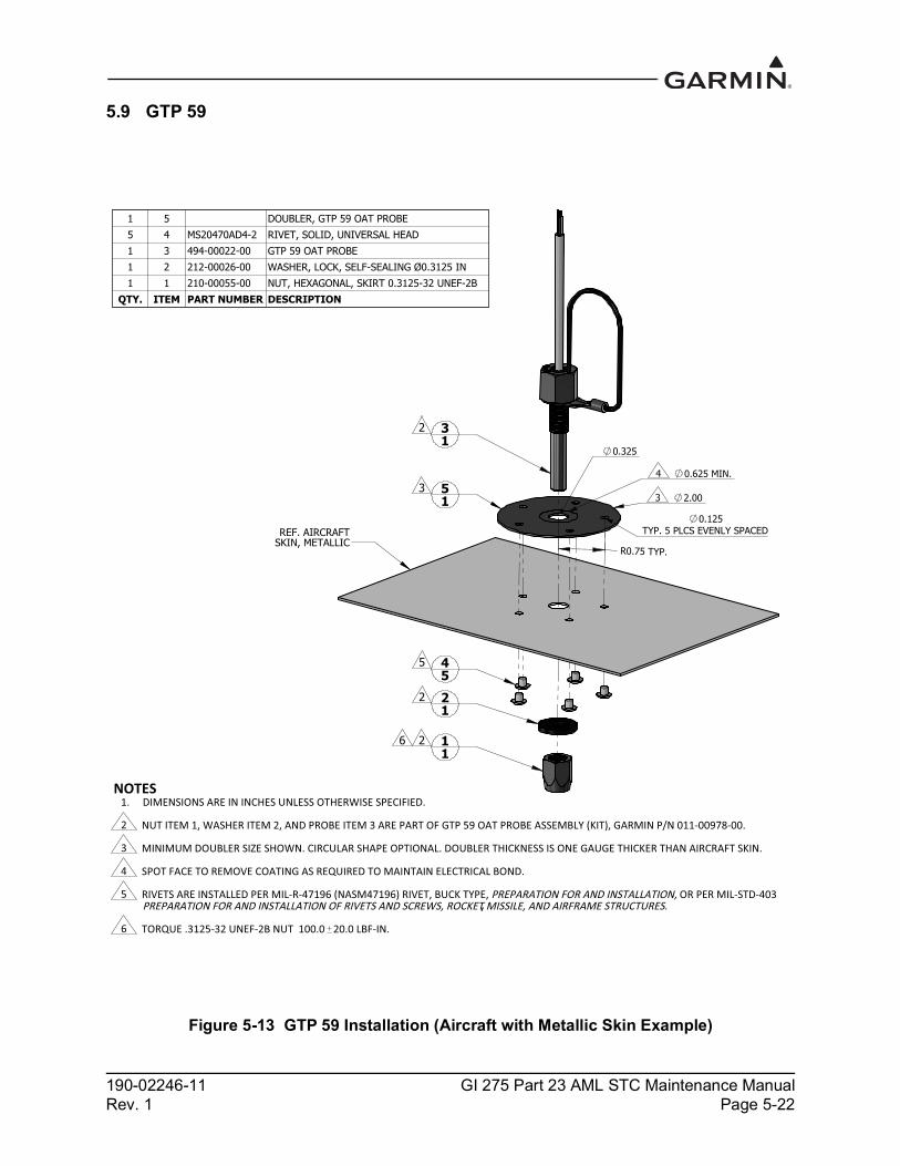
190-02246-11 GI 275 Part 23 AML STC Maintenance ManualRev. 1 Page 5-22
5.9 GTP 59
Figure 5-13 GTP 59 Installation (Aircraft with Metallic Skin Example)
,

190-02246-11 GI 275 Part 23 AML STC Maintenance ManualRev. 1 Page 5-23
5.9.1 GTP 59 RemovalTo remove the GTP 59, perform the following procedure:
1. Remove power from the GI 275 that is directly interfaced to the GTP 59. 2. Remove the mounting nut shown in Figure 5-13.3. Remove the GTP 59 from the hole.
5.9.2 GTP 59 Re-installation1. Place the GTP 59 in the previous installation hole.2. Install washer and nut and torque to specifications in Figure 5-13.
5.9.3 GTP 59 CheckoutPerform the Primary ADI checkout procedures in Section 6 of GI 275 Part 23 AML STC Installation Manual (P/N 190-02246-10).
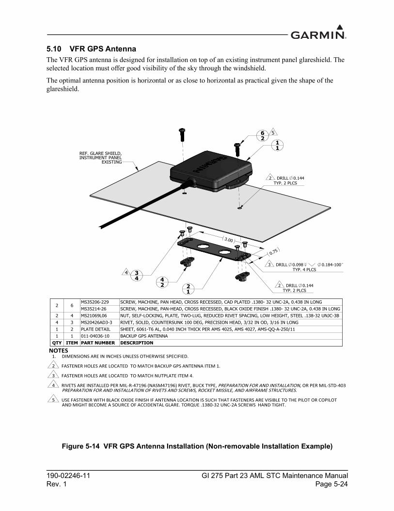
190-02246-11 GI 275 Part 23 AML STC Maintenance ManualRev. 1 Page 5-24
5.10 VFR GPS AntennaThe VFR GPS antenna is designed for installation on top of an existing instrument panel glareshield. The selected location must offer good visibility of the sky through the windshield.
The optimal antenna position is horizontal or as close to horizontal as practical given the shape of the glareshield.
Figure 5-14 VFR GPS Antenna Installation (Non-removable Installation Example)

190-02246-11 GI 275 Part 23 AML STC Maintenance ManualRev. 1 Page 5-25
Figure 5-15 VFR GPS Antenna Installation (Removable Installation Example)
5.10.1 VFR GPS Antenna RemovalUse the following procedure to remove the VFR GPS antenna:
1. Remove power from the GI 275 connected to the VFR GPS antenna.2. Disengage the BNC connector from the GI 275.3. Remove the two screws securing the antenna (if installed per Figure 5-14 only).4. Lift up on the VFR GPS antenna to remove it.
5.10.2 VFR GPS Antenna Re-installationInstall the VFR GPS antenna in the reverse order of the removal procedure.
5.10.3 VFR GPS Antenna CheckoutPerform the Backup GPS Signal Check as described in Section 6 of GI 275 Part 23 AML STC Installation Manual (P/N 190-02246-10) or GI 275 EIS & MFD Installation Manual (P/N 190-02246-14).
2.0
11
21
31
REF. GLARE SHIELD, INSTRUMENT PANEL
EXISTING
22
2
NOTESDIMENSIONS ARE IN INCHES UNLESS OTHERWISE SPECIFIED.1.
2 PEEL OFF ADHESIVE PROTECTING FILM AND PRESS THE FASTENER TAPE IN TO BOND. SURFACES MUST BE CLEAN AND FREE FROM OIL OR OTHER CONTAMINANTS. LOOP FASTENER IS BONDED TO GLARE SHIELD AND HOOK FASTENER IS BONDED TO ANTENNA. TAPE FASTENER MUST BE 2.0 INCHES OR LONGER.
3 GPS ANTENNA KIT, GARMIN PART NO. 010-12444-00 INCLUDES DUAL LOCK FASTENER, GARMIN PART NO. 252-00433-00 WHICH CAN BE USED INSTEAD OF A-A-55126 FASTENER TAPE.
QTY ITEM PART NUMBER DESCRIPTION
13
A-A-55126 3FASTENER TAPE, SYNTHETIC, ADHESIVE BACKED, A-A-55126 CLASS 1/2, TYPE 1, LOOP 1.0 INCH WIDE
2 FASTENER TAPE, SYNTHETIC, ADHESIVE BACKED, A-A-55126 CLASS 1/2, TYPE 1, HOOK 1.0 INCH WIDE
1 1 011-04036- 0 BACKUP GPS ANTENNA
190-02246-11 GI 275 Part 23 AML STC Maintenance ManualRev. 1 Page 5-26
5.11 EIS SensorsIn addition to the data in this manual, replacement or re-installation of each probe/sensor and wire must be accomplished in accordance with the sensor manufacturer instructions or as recommended by the engine manufacturer. Wire routing and clamping must follow procedures defined in the aircraft maintenance manual, standard practices manual, or practices defined in Chapter 11, Electrical Systems, of AC 43.13-1B Aircraft Inspection and Repair.
Sensors must be connected using hoses and fittings approved as part of aircraft or engine type certificated design or standard aircraft parts (AN/MS).
After removing or replacing any EIS sensor, perform the EIS ground checkout procedure in Section 6 of the GI 275 installation manuals (refer to Table 1-1) for the sensor that was affected.
CAUTIONCheck hose routing for sharp bends. Check sensors and fittings for leaks during engine run-up and correct prior to flight.

190-02246-11 GI 275 Part 23 AML STC Maintenance ManualRev. 1 Page 5-27
5.11.1 Carburetor/Induction Air TemperatureThe sensor location will vary for different carburetors. Refer to the engine or carburetor manufacturer data for temperature sensor location, if required.
Figure 5-16 Carburetor Temperature Sensor Installation Example
CAUTIONFuel and air passages must remain free of contaminants during work near and around the carburetor.
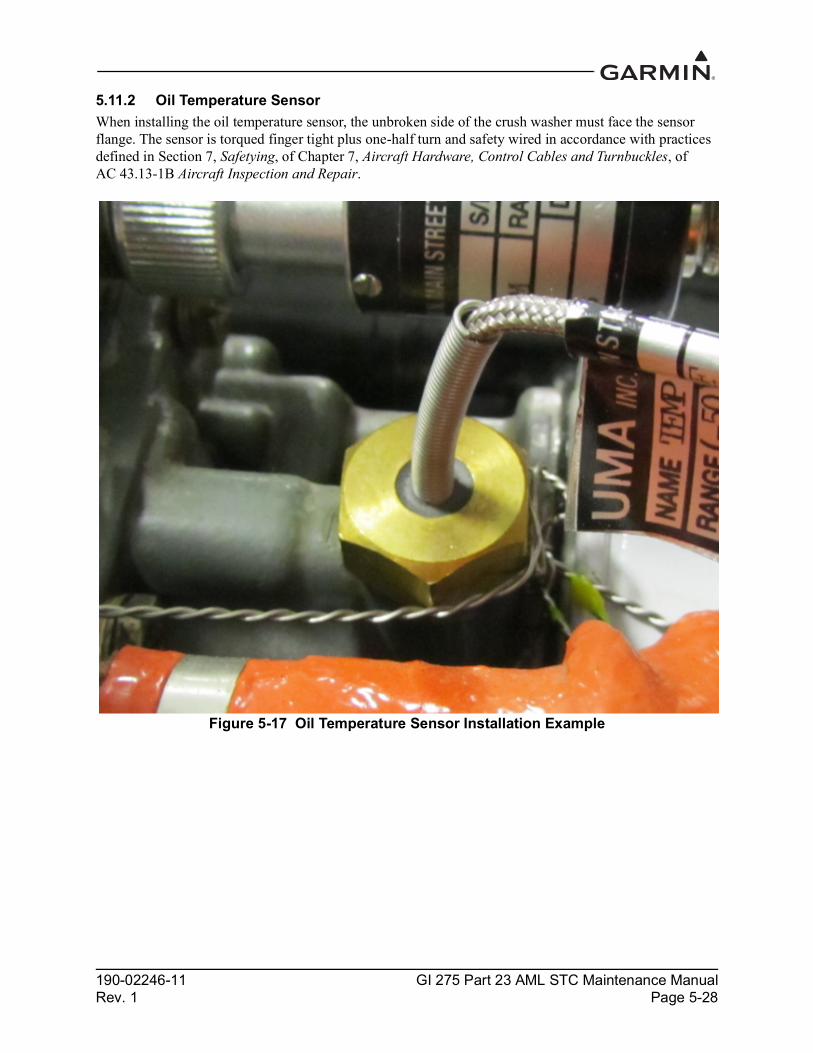
190-02246-11 GI 275 Part 23 AML STC Maintenance ManualRev. 1 Page 5-28
5.11.2 Oil Temperature SensorWhen installing the oil temperature sensor, the unbroken side of the crush washer must face the sensor flange. The sensor is torqued finger tight plus one-half turn and safety wired in accordance with practices defined in Section 7, Safetying, of Chapter 7, Aircraft Hardware, Control Cables and Turnbuckles, of AC 43.13-1B Aircraft Inspection and Repair.
Figure 5-17 Oil Temperature Sensor Installation Example

190-02246-11 GI 275 Part 23 AML STC Maintenance ManualRev. 1 Page 5-29
5.11.3 Pressure SensorsManifold pressure, oil pressure, and fuel pressure sensor installations are similar. Garmin pressure sensors with a brass housing are limited to aircraft with operational ceilings up to 32,000 feet. Garmin pressure sensors with a stainless steel housing may be used on all aircraft on the AML.
When replacing existing sensors:• Do not remove engine and fuel fittings with an intentionally reduced orifice. It may limit fluid loss
and fire damage in the event of a hose failure• Inspect the condition of all existing tubes, hoses, and fittings that are being reused; replace if
necessary
When installing pressure sensors:• Fuel and oil hoses in the engine compartment must meet TSO-C53a Type C or D (fire resistant)• Do not install sensors directly below fittings or components that may leak flammable fluid• Thread sealant or tape must be used for the NPT threads. To reduce the risk of system
contamination, a minimal amount of sealant should be applied leaving at least two threads at the end of the fitting clear of sealant/tape
• Sensors must be routed as far away from the aircraft exhaust system as practical and no closer than 6 inches
Table 5-1 Pressure Sensor Equipment ListFunction Manufacturer P/N, Description Garmin P/N Authorization
Oil PressKavlico P4055-5020-4, Press (Brass)
011-04202-30(494-30027-30) GI 275 STC
Kulite APT-20GX-1000-150G, Press (Stainless) 494-30032-00
Manifold PressKavlico P4055-5020-1, Press (Brass)
011-04202-00(494-30027-00) GI 275 STC
Kulite APT-20GX-1000-25PSIA, Press (Stainless) 494-30030-00
Fuel Press
Kavlico P4055-5020-3, Press (Brass)011-04202-20(494-30027-20)
GI 275 STCKavlico P4055-5020-2, Press (Brass)011-04202-10(494-30027-10)
APT-20GX-1000-50PSIG, Press (Stainless) 494-30031-00APT-20GX-1000-15PSIG, Press (Stainless) 494-30029-00

190-02246-11 GI 275 Part 23 AML STC Maintenance ManualRev. 1 Page 5-30
Figure 5-18 Brass Sensor Installation (Coupling Mount Example)

190-02246-11 GI 275 Part 23 AML STC Maintenance ManualRev. 1 Page 5-31
Figure 5-19 Stainless Steel Sensor Installation (Housing Mount Example)

190-02246-11 GI 275 Part 23 AML STC Maintenance ManualRev. 1 Page 5-32
5.11.4 Fuel FlowThe fuel flow transducer can be mounted using the bracket or clamping hoses connected to the transducer. If mounting with clamps, the placement must be no further than 6 inches from the clamp to the nearest face of the transducer.
• The transducer can be oriented with the wires pointing up, or the cap with five bolts pointing up, or the output port pointing up, or any combination thereof
• The hose connected to the IN port must be straight for a minimum of 4 inches• The hose connected to the OUT port should be level or slope up. It must not slope down more than
4 inches per foot
Hoses and fittings connected to fuel flow transducer must meet the following: 1. New hoses must have the same internal diameter as the hose being replaced and meet TSO-C53a
Type C or D (fire resistant) specifications.2. Fuel compatible thread sealant or tape must be used for the NPT threads. To reduce the risk of fuel
system contamination, a minimal amount of sealant should be applied leaving at least two threads at the end of the fitting clear of sealant/tape.
3. Fitting torque must not exceed 12 ft-lbf or two full turns past finger tight, whichever occurs first.4. The transducer and fuel hoses must be routed as far away from the aircraft exhaust system as
practical. The transducer must be protected with Aeroquip AE102-( ) fire-sleeve if within 6 inches of any exhaust component.
WARNINGEnsure the fuel flow transducer installation does not introduce thread sealant or debris into the fuel system.
CAUTIONDo not blow pressurized air through the flow transducer.
If the fuel flow transducer bracket must be replaced, the replacement bracket must be fabricated from 300 series austenitic stainless steel (annealed per AMS 5901 or ½ hard per AMS 5517), sheet thickness 19 gauge minimum (0.044 inches) and installed as provisioned by the aircraft structural repair manual or standard practices manual. Methods, techniques, and practices defined in Chapter 4, Metal Structure, Welding and Brazing, of AC 43.13-1B Aircraft Inspection and Repair are acceptable.

190-02246-11 GI 275 Part 23 AML STC Maintenance ManualRev. 1 Page 5-33
Figure 5-20 Fuel Flow Transducer Installation
5.11.5 Engine RPMThe GI 275 system can use the electrical signal generated by the primary magneto coils or “P-Lead” to display RPM. When used, the left and right magneto P-Lead signals must both be connected to the GEA 24/110. The connection can be made at the magneto or the ignition switch.
To replace the P-Lead wire, remove the old section of wire and replace the entire wire and parallel resistors in accordance with the P-Lead installation instructions contained in Section 4 of the GI 275 installation manuals (refer to Table 1-1).

190-02246-11 GI 275 Part 23 AML STC Maintenance ManualRev. 1 Page 5-34
5.12 CalibrationThis section provides guidance for calibrating the GI 275 system if the previous calibration has become invalid.
5.12.1 Attitude/HeadingIf it becomes necessary to re-calibrate any installed AHRS, refer to the calibration procedures contained in Section 5 and Section 6 of GI 275 Part 23 AML STC Installation Manual (P/N 190-02246-10).
5.12.2 Autopilot CalibrationIf it becomes necessary to re-calibrate the autopilot, refer to the calibration procedure contained in GI 275 Part 23 AML STC Installation Manual (P/N 190-02246-10).
5.12.3 Analog NAV CalibrationIf it becomes necessary to re-calibrate the Analog NAV, refer to the calibration procedure contained in Section 6 of the GI 275 installation manuals (refer to Table 1-1).
5.12.4 Fuel Level CalibrationIf it becomes necessary to re-calibrate the fuel level, refer to the calibration procedure contained in the GI 275 installation manuals (refer to Table 1-1).
5.12.5 Backup Battery CheckThis procedure will analyze the voltage and discharge qualities of the installed backup battery. The procedure is required to be completed on initial installation and every 12 calendar months when a backup battery is installed in the system. A fault indication message will be displayed in Normal mode until this procedure is completed.
NOTEThe battery rundown test may take up to 150 minutes to complete.
NOTEThe battery rundown test date is reported in UTC.
To complete the backup battery test, complete the following steps: 1. Power on each GI 275 with an installed backup battery in Configuration mode.2. Navigate to the Backup Battery Test page (Calibration/Test → Backup Battery Test).3. Touch the Before Test Checklist button.4. Verify that “Discharging” is not displayed under Battery State.5. Touch the Test Date button and enter the current date.6. Complete the on-screen checklist. Touch each checklist item once completed. Once all checklist
items have a green check mark, touch the Back button.7. Touch the Start Test button and follow the on-screen commands.8. The GI 275 will power off automatically when the test is completed.9. Power on the GI 275(s) in Configuration mode and navigate to the Backup Battery Test page.

190-02246-11 GI 275 Part 23 AML STC Maintenance ManualRev. 1 Page 5-35
10. Touch the Test Results button and then Rundown Test Results button.a. The results are displayed the date the test was performed and how many minutes until the
battery ran down.11. For aircraft that are approved for flight over 25,000 feet, a rundown time of at least 60 minutes is
required to be considered a PASS.
For aircraft that are only approved for flight at 25,000 feet or less, a rundown time of at least 30 minutes is required to be considered a PASS.
12. If the test results were not a PASS as described in the previous step, the battery must be replaced using the procedure in Section 5.5.

190-02246-11 GI 275 Part 23 AML STC Maintenance ManualRev. 1 Page 5-36
5.13 Uploading SoftwareThe SW/Config page is used to update the software for the GI 275 and any LRUs directly interfaced to the GI 275. The approved software version and part numbers can be found in the most recent revision of GI 275 Part 23 AML STC Equipment List (P/N 005-01208-42). Ensure the Unit ID is properly configured prior to loading software to the GI 275. After loading software to the GI 275, configure all interfaced LRUs.
Software updates can be accomplished via USB using the following procedure:1. Create a Software Loader Card using the latest software and instructions available on the Garmin
Dealer Resource Center.2. Power on all GI 275s in the system in Configuration mode.3. Insert the USB drive into the USB dongle or GSB 15 (if installed). A USB icon should appear on
the left of the display once the GI 275 has recognized the device. If the icon doesn’t appear after 1 minute, remove the drive and re-insert it.
4. Navigate to the Loader Card page (SW/Config → Loader Card).5. Select the applicable updates or touch the Select All button.6. Touch Update Packages ( ) and then Begin Update. A restart is required when completed.

190-02246-11 GI 275 Part 23 AML STC Maintenance ManualRev. 1 Page 5-37
5.14 System ChecksPeriodic system checks that do not require a Garmin dealer to perform are contained in this section. For complete system checkout procedures, refer to Section 6 of the GI 275 installation manuals (refer to Table 1-1).
5.14.1 Configuration Ground CheckThe configuration ground check procedures are intended to verify that each LRU and interface in the GI 275 system has been properly configured. Steps not applicable to a particular installation may be skipped.
NOTEThroughout the configuration ground check section, references are made to particular functions and screens. If a function or screen is not available, ensure that the system has been configured correctly.
The configuration ground checks must be performed on every GI 275. Before starting the configuration mode checkout, the following conditions must be met:
1. All GI 275 displays in the system must be powered on in Configuration mode. 2. All system LRUs must be powered on.3. All installed LRUs must be configured per the printed configuration log contained in Section 5.
5.14.1.1 LRU Status checkThe System Info page contains the Devices Online page, which reports the status of installed LRUs. The icon next to each LRU reports one of three colored symbols to indicate the status of each LRU, as described in Table 5-2. Verify that all LRUs connected or configured to each display have a green checkmark indicator.
Table 5-2 LRU Status Indicators
5.14.1.2 Device InfoThe Device Info page (System Info → Device Info) provides information for each configured LRU as part of the GI 275 system.
1. Touch the Device button and select an interfaced LRU.2. Verify that all software versions are up-to-date for the interfaced LRU.3. Repeat steps 1 and 2 for each interfaced LRU.
Status Color LRU ConditionGreen Checkmark The LRU is online. No faults are detected.Yellow Question Mark The LRU is configured but not sending any data.Red X The LRU is online. A fault, warning, and/or error is detected.(Empty) The LRU is not configured.
190-02246-11 GI 275 Part 23 AML STC Maintenance ManualRev. 1 Page 5-38
5.14.2 Pitot-Static and Airspeed Tape Settings ChecksThe following section verifies the correct operation of the GI 275 altitude and airspeed tapes, standby altimeter, and standby airspeed indicator using a pitot-static ramp tester. When using a pitot-static ramp tester, only simulate normal aircraft operating conditions as defined in the aircraft Type Data (POH/AFM) or other approved STC to avoid component damage.
NOTEThe ADC may require a warm-up period of 15 minutes to reach full accuracy; however, 30 minutes may be required if the environmental temperature is below 0º C.
The GI 275 airspeed tape display and settings must be verified using the procedures in Section 5.14.2.1 or Section 5.14.2.2 depending on the airspeed tape configuration (Basic or Advanced, respectively). The airspeeds referenced in the following steps must match those shown in the printed configuration log.
5.14.2.1 Basic Airspeed Tape SettingIf the airspeed Configuration Type is set to Basic (Setup → Airframe Config → Airspeed Configuration), verify correct operation of the internal ADAHRS as follows:
NOTEIf the internal ADAHRS and standby airspeed indicator are on separate pitot-static systems, it is recommended to set up the test set so that both systems can be tested at the same time, or separate tests must be completed for each system.
1. Power on the GI 275 system in Normal mode.2. Using a pitot-static test set, increase the airspeed until the ADI airspeed tape pointer is at the
bottom of the white band (Vs0). 3. Verify that the bottom of the white arc/band on the standby ASI and ADI airspeed tape are at the
same airspeed value.4. For twin-engine aircraft with a minimum control speed: Increase the airspeed to the lower red
radial (Vmca). Verify that the red radial on the standby ASI and ADI airspeed tape are at the same airspeed value.
5. Change the airspeed until the ADI airspeed tape pointer is at the bottom of the green band (Vs1). 6. Verify that the bottom of the green arc/band on the standby ASI and ADI airspeed tape are at the
same airspeed value. 7. For twin-engine aircraft only: Increase the airspeed to the blue radial (Vyse). Verify that the blue
radial on the standby ASI and ADI airspeed tape are at the same airspeed value. 8. Change the airspeed until the ADI airspeed tape pointer is at the top of the white band (Vfe). 9. Verify that the top of the white arc/band on the standby ASI and ADI airspeed tape are at the same
airspeed value.10. Change the airspeed until the ADI airspeed tape pointer is at the top of the green band/bottom of
the yellow band (Vno).11. Verify that the top of the green arc/band on the standby ASI and ADI airspeed tape are at the same
airspeed value. 12. Increase the airspeed to the upper red radial/top of yellow arc (Vne).13. Verify that the red radial on the standby ASI and ADI airspeed tape are at the same airspeed value.

190-02246-11 GI 275 Part 23 AML STC Maintenance ManualRev. 1 Page 5-39
14. Starting at the current airspeed, decrease the airspeed to zero, stopping at each of the airspeeds listed in Table 5-3 (airspeeds above Vne should not be checked), verifying that the ADI and standby ASI airspeed values are within the tolerances indicated in Table 5-3.
Table 5-3 Airspeed Test Points
5.14.2.2 Advanced Airspeed Tape SettingIf the Configuration Type is set to Advanced, verify correct operation of the internal ADAHRS as follows:
NOTEIf the internal ADAHRS and standby airspeed indicator are on separate pitot-static systems, it is recommended to set up the test set so that both systems can be tested at the same time, or separate tests must be completed for each system.
1. Power on the GI 275 system in Normal mode.2. Using a pitot-static test set, increase the airspeed until the ADI airspeed tape pointer is at the
bottom of the white band (Vs0).3. Verify that the bottom of the white arc/band on the standby ASI and ADI airspeed tape are at the
same airspeed value.4. Increase the IAS throughout the range of the ASI – stop at the limits of all Arc Ranges, and at all
Marking values configured per the instructions in Table 5-4 and Table 5-5 and listed in the printed configuration log.
5. Verify that the ranges and markings on the standby ASI and ADI are located at the same airspeed values. The last value verified should be the beginning of the barber pole (Vne/Vmo/Mmo).
6. The following applies to Variable Vne/Vmo/Mmo aircraft only:
a. Decrease the IAS to 25 knots below the barber pole on the ADI. Increase the indicated altitude to the maximum operating altitude or service ceiling. Verify that the barber pole on the ADI and standby ASI are at the same airspeed (±5 kt). Decrease the airspeed as needed to ensure the IAS does not exceed the barber pole during the simulated climb.
b. Decrease the indicated altitude (do not exceed vertical speed limitations) back to ambient static pressure.
7. Starting at the current airspeed, decrease the airspeed to zero, stopping at all of the relevant airspeeds listed in Table 5-3 (airspeeds above Vne should not be checked). Verify that the ADI and standby ASI values are within the tolerances indicated.
Test Set Airspeed (kt) PFD Allowed Tolerance (kt)50 ±5.080 ±3.5100 ±2.0120 ±2.0150 ±2.0180 ±2.0210 ±2.0250 ±2.0290 ±3.0

190-02246-11 GI 275 Part 23 AML STC Maintenance ManualRev. 1 Page 5-40
Table 5-4 Advanced Airframe Specific Configuration Data – Arc Ranges
Arc Color Description POH/AFM Section Notes
RED(LOW SPEED)
Low speed awareness 2 - Limitations
If the aircraft has a defined WHITE or GREEN arc, set the RED arc to ON. Set the MAX value of the RED arc to the lowest value of the WHITE or GREEN arc (Vs0). A RED low-speed awareness arc will appear below the lowest marked stall speed.If the aircraft does not have defined white or green arc, set the red arc to OFF, and enter the lowest stall speed in the STALL SPEED setting at the bottom of the page.
WHITE Full flap operational range 2 - Limitations
Set the Min value to the bottom of the POH/AFM defined range.If WHITE and GREEN arcs overlap, set the Max value to the beginning of the WHITE/GREEN arc.If WHITE and GREEN arcs do not overlap, set the Max value to the top of the POH/AFM or aircraft specification defined range.If a WHITE arc is not defined by the AFM/POH or aircraft specifications, set both the Min and Max values to the aircraft stall speed in the landing configuration (Vs0). This setting will not display a white arc, but the system needs it to characterize aircraft performance.
HALF WHITE Standard operational range 2 - Limitations
If the HALF WHITE arc range is not defined by the AFM/POH or aircraft specification, set to OFF.This may sometimes be called a “narrow WHITE arc”.
WHITE/GREEN
Overlap between standard operational and flaps operational ranges
2 - Limitations
If a WHITE/GREEN arc is not defined by the AFM/POH or aircraft specification, set to OFF.If WHITE and GREEN arcs overlap, configure to the range they overlap within.
GREEN Standard operational range 2 - Limitations
If the GREEN arc is not defined by the AFM/POH or aircraft specification, set to OFF.If WHITE and GREEN arcs overlap, set Min value to the Max of WHITE/GREEN.If the YELLOW arc is defined, set to the Min of the YELLOW arc (Vno).If the YELLOW arc is not defined, set Max value to Vno/Vne.

190-02246-11 GI 275 Part 23 AML STC Maintenance ManualRev. 1 Page 5-41
Table 5-5 Advanced Airframe Specific Configuration Data – Markings
YELLOW Caution / smooth air operational range 2 - Limitations
If the YELLOW arc is defined by the AFM/POH or aircraft specification, set to ON with Min value equal to Maximum structural speed (Vno). Max value should be configured to Vne, or the highest value of Vne if variable.If the YELLOW arc is not defined, set to OFF.
Vne/Vmo/Mmo
Never exceed speed/ max operating speed/ max operating mach number
2 - Limitations
If defined as a fixed value, set to Fixed, and enter POH/AFM defined Vne/Vmo as the Min value. If variable with altitude, set to Variable, and set overspeeds in accordance with Appendix E in GI 275 Part 23 AML STC Installation Manual.
Marking Description POH/AFMSection Note
Vle Maximum landing gear extended speed 2 - Limitations Set to OFF for fixed gear
aircraft.
BLUE BARTypically marks the single engine best rate-of-climb speed for a twin-engine aircraft
3 - Emergency Procedures
Blue radial on ASI of light twins.Set to OFF for single-engine aircraft.
RED BAR
Typically marks the minimum controllable airspeed for twin-engine aircraft with only one engine operational (Vmca)
3 - Emergency Procedures
Lower red radial on ASI of light twins.Set to OFF for single-engine aircraft.
RED/WHITE BAR Varies – sometimes used as a fixed point Vne marking 2 - Limitations
If a fixed RED/WHITE bar, (not a barber pole) is shown in the POH/AFM, set to given value. Else, set to OFF.
WHITE TRIANGLE A small white triangle – meaning varies by airframe 2 - Limitations If defined in POH/AFM, set to
given value. Else, set to OFF.
Arc Color Description POH/AFM Section Notes

190-02246-11 GI 275 Part 23 AML STC Maintenance ManualRev. 1 Page 5-42
5.14.2.3 Altimeter CheckThe GI 275 standby altitude displays must be verified per Title 14 of the CFR 91.411 and Part 43 Appendix E, with the following exception to 14 CFR Part 43 Appendix E, paragraph (b)(1):
• The tests of sub-paragraphs (iv) (Friction) and (vi) (Barometric Scale Error) are not applicable to the GI 275 due to the internal ADAHRS interface and instrument display being digital
5.14.2.4 Calibrate Static PressureThis procedure is used to perform an altimeter calibration, if required.
The Static Pressure Calibration requires the use of a pressure control system (test set) with an altitude accuracy of at least ±5 feet at sea level and ±20 feet at 30,000 feet. It is necessary to re-calibrate to sea level (0 feet), 10,000 feet, 20,000 feet, and optionally to 30,000 feet. The calibration is allowed to be finished after the 20,000 feet calibration if the aircraft operational ceiling is below 20,000 feet.
CAUTIONTo avoid damaging the GI 275 pressure sensors, both the pitot and static ports must be connected to the test set.
CAUTIONPrior to performing the Calibrate Static Pressure procedure, perform a Static System Leak Test in accordance with 14 CFR Part 43 Appendix E.
1. Navigate to the Calibrate Static Pressure page (Calibration/Test → Attitude/Heading → Calibrate Static Pressure).
2. Ensure the on-screen instructions have been followed. Touch the OK/Next/Start buttons to continue to the next screen.
3. At each calibration point, the display will indicate the pressure altitude to set (e.g., “Set pressure to sea level”). Once the altitude is set, touch Ready to calibrate.a. During the calibration at each pressure, the pressure must be held constant for 30 seconds for
the calibration step to be successful. The calibration may be canceled at any point should the test setup require adjustment before repeating.
4. Select Done when the calibration is successfully completed.

GI 275 Part 23 AML STC Maintenance Manual Page A-1 190-02246-11
Rev. 1
APPENDIX A: INSTALLATION SPECIFIC INFORMATION
A.1 General Information
Date:_______ /_________ /__________ By:_____________________________________________
AIRCRAFT
AIRCRAFT YEAR: _________________________________________________________________
AIRCRAFT MAKE: _________________________________________________________________
AIRCRAFT MODEL: _________________________________________________________________
AIRCRAFT SERIAL #: _________________________________________________________________
AIRCRAFT REG. #: _________________________________________________________________
Installed System
GI 275
GI 1 Base ADAHRS ADAHRS+AP ADI HSI MFD/Standby ADI HSI/Standby ADI MFD EIS
GI 2
GI 3
GI 4
GI 5
GI 6
Base ADAHRS ADAHRS+AP Base ADAHRS ADAHRS+AP Base ADAHRS ADAHRS+AP Base ADAHRS ADAHRS+AP Base ADAHRS ADAHRS+AP
ADI HSI MFD/Standby ADI HSI/Standby ADI MFD EIS
ADI HSI MFD/Standby ADI HSI/Standby ADI MFD EIS
ADI HSI MFD/Standby ADI HSI/Standby ADI MFD EIS
ADI HSI MFD/Standby ADI HSI/Standby ADI MFD EIS
ADI HSI MFD/Standby ADI HSI/Standby ADI MFD EIS

GI 275 Part 23 AML STC Maintenance Manual Page A-2 190-02246-11
Rev. 1
A.2 LRU InformationFor each unit included in the installation, record the LRU information in the table below.
Unit Part Number Serial Number Mod Level GI 275 #1 011-04489-
GI 275 #2 011-04489-
GI 275 #3 011-04489-
GI 275 #4 011-04489-
GI 275 #5 011-04489-
GI 275 #6 011-04489-
GMU 11 #1 011-04349-
GMU 11 #2 011-04349-
GMU 44B #1 011-04201-
GMU 44B #2 011-04201-
GTP 59 #1 011-00978-
GTP 59 #2 011-00978-
VFR GPS Antenna 011-04036-
GEA 24 #1 011-02848-
GEA 24 #2 011-02848-
GEA 110 #1 011-03454-
GEA 110 #2 011-03454-
Backup Battery 011-04528-
GSB 15 011-04937-

GI 275 Part 23 AML STC Maintenance Manual Page A-3 190-02246-11
Rev. 1
A.3 Equipment LocationFor each unit included in the installation, record the fuselage station and provide a brief description of the location.
Unit Station
Description of Location GI 275 #1 in.
GI 275 #2 in.
GI 275 #3 in.
GI 275 #4 in.
GI 275 #5 in.
GI 275 #6 in.
GMU 11 #1 in.
GMU 11 #2 in.
GMU 44B #1 in.
GMU 44B #2 in.
GTP 59 #1 in.
GTP 59 #2 in.
GEA 24 #1 in.
GEA 24 #2 In.
GEA 110 #1 in.
GEA 110 #2 in.
Backup Batt in.
GSB 15 in.

GI 275 Part 23 AML STC Maintenance Manual Page A-4 190-02246-11
Rev. 1
A.4 Wire Routing – Single-EngineThe following diagram depicts the wire routing for the GI 275 LRUs throughout the aircraft structure for a single-engine aircraft:

GI 275 Part 23 AML STC Maintenance Manual Page A-5 190-02246-11
Rev. 1
A.5 Wire Routing – Twin-EngineThe following diagram depicts the wire routing for the GI 275 LRUs throughout the aircraft structure for a twin-engine aircraft:
GI 275 Part 23 AML STC Maintenance Manual Page A-6 190-02246-11
Rev. 1
A.6 Saved Configuration FileThe GI 275 system configuration must be saved to a USB drive and placed with the permanent aircraft maintenance records. For instructions on saving the aircraft configuration file to a USB drive, refer to Section 2.1.10. It is recommended that the USB drive be taped or otherwise secured to this page in the location marked below.
Aircraft Configuration USB drive
A.7 Print Configuration LogThe GI 275 system configuration log must be printed out and included with the permanent aircraft maintenance records. To print the system configuration log, perform the following procedure:
1. Save the aircraft configuration file to a USB drive (refer to Section 2.1.10).2. Insert the USB drive into a computer.3. Open the USB drive main directory.4. Navigate to the “summary” folder.5. Open the file with the name you entered to save your aircraft configuration.6. Print the configuration log.
7. NOTEIt is recommended that the configuration log be attached to the back of this document forcontinuity and ease of use. It is required that the MM/ICA, USB drive, and configuration logbe included in the permanent aircraft maintenance records.
The configuration log printout contains configuration info for configured EIS gauges, including configured markings and gauge layout for each GI 275 displaying EIS gauges.