Embed Size (px)
Citation preview

Tech
nic
al I
nfo
rmat
ion
GH
IBLI
4-5
-6 E
LITE
Gas-fired convective air heaters
GHIBLI 4-5-6 ELITE
Cod. 25619502IT - Rev. 0 - 20/03/2013

GAS FIRED CONVECTION HEATERS WITH FAN
GHIBLI SERIES
Models 4 - 5 - 6
Technical information
This manual is divided into three sections:
- SECTION 1 - GENERAL INFORMATION
It contains all the information relevant to the description of the heaters and their technical features
- SECTION 2 - TECHNICAL INFORMATION FOR THE INSTALLER
It contains all the instructions that the technical installer must comply with to ensure effective plantoperation
- SECTION 3 - USER OPERATING AND MAINTENANCE INSTRUCTIONS
The section is reserved for the user and contains all the information needed to use the appliancecorrectly and to perform periodic tests
Important notes:
1 - To use the appliance correctly and safely, the installer, the user and the service man, must complywith what is indicated in this manual.
2 - The word WARNING! is followed by information which, because of its importance, must be carefullyobserved and for which non-compliance may damage the appliance and/or reduce operating safety.
3 - The paragraphs written with bold characters contain important information, warnings orrecommendations which should be carefully considered.
4 - The technical data, styling characteristics, components and accessories detailed in this manual are
not binding. A2B ACCORRONI E.G. S.r.l. reserves the right to make changes, at any time, that are considered necessary to improve the product.
5 - The legal references, standards and technical rules mentioned in this manual are presented merely
for the sake of information and should be considered valid as of the date this manual is printed, as indicated on the last page. If new regulations or amendments to current laws go into effect, this will not obligate A2B ACCORRONI E.G. S.r.l. in any way with regard to others.
6 - A2B ACCORRONI E.G. S.r.l. is responsible for ensuring that its product conforms to the laws, directives andconstruction standards in force at the time the product is sold. Knowledge and compliance with legal regulations and standards regarding plant design, installation, operation and maintenance are the exclusive responsibility of the designer, installer and user.
SUMMARY
SECTION 1 - GENERAL INFORMATION page
1. PRINCIPAL CHARACTERISTICS .......................................................................................... 41.1 Appliance classification ........................................................................................................... 41.2 Certification - EC marking ....................................................................................................... 41.3 Functional description ............................................................................................................. 41.4 Construction characteristics .................................................................................................... 51.5 Package contents ................................................................................................................... 51.6 Accessories supplied on request ............................................................................................ 51.7 Application .............................................................................................................................. 51.8 Dimensions ............................................................................................................................. 61.9 Wiring diagram........................................................................................................................ 71.10 Technical data table ................................................................................................................ 81.11 Exploded view ......................................................................................................................... 9

page 2
2. CONTROL AND SAFETY DEVICES .................................................................................. 122.1 Gas controller ....................................................................................................................... 122.2 Gas unit ................................................................................................................................. 122.3 Fan thermostat ...................................................................................................................... 122.4 Safety thermostat .................................................................................................................. 12
SECTION 2 - TECHNICAL INFORMATION FOR THE INSTALLER
3. PRECAUTIONS ................................................................................................................... 133.1 Gas safety regulations .......................................................................................................... 133.2 Related documents ............................................................................................................... 133.3 Transport and handling ......................................................................................................... 133.4 Data check ............................................................................................................................ 133.5 Using the instructions ........................................................................................................... 13
4. INSTALLATION .................................................................................................................... 134.1 Positioning instructions ......................................................................................................... 134.2 Air intake and flue exhaust ducts .......................................................................................... 144.3 Outside positioning of the flue gas exhaust terminal ............................................................. 154.4 Installation operations ........................................................................................................... 15
5. START-UP ........................................................................................................................... 185.1 Tests ..................................................................................................................................... 185.2 Ignition ................................................................................................................................... 195.3 Useful information ................................................................................................................. 19
6. GAS TYPE CHANGE .......................................................................................................... 206.1 Switching from gas in the second group to gas in the third group ........................................ 206.2 Switching from gas in the third group to gas in the second group ........................................ 20
7. OPERATING DEFECTS ...................................................................................................... 217.1 Preliminary tests ................................................................................................................... 217.2 Possible defects ................................................................................................................... 21
8. REPLACING PARTS ........................................................................................................... 238.1 Control equipment ................................................................................................................. 238.2 Fuse ...................................................................................................................................... 238.3 Gas solenoid valves .............................................................................................................. 238.4 Convection fan control thermostat ........................................................................................ 238.5 Safety limit thermostat .......................................................................................................... 238.6 Electrodes ............................................................................................................................. 248.7 Flue exhaust fan.................................................................................................................... 248.8 Convection fan ...................................................................................................................... 24
9. PERIODIC MAINTENANCE OPERATIONS....................................................................... 259.1 User information.................................................................................................................... 259.2 Yearly inspection ................................................................................................................... 25
SECTION 3 - USER OPERATING AND MAINTENANCE INSTRUCTIONS
10. START-UP ........................................................................................................................... 2610.1 First firing and testing ............................................................................................................ 2610.2 Tests ..................................................................................................................................... 2610.3 Ignition ................................................................................................................................... 2610.4 Shutdown .............................................................................................................................. 2611. APPLIANCE MAINTENANCE ............................................................................................. 2711.1 Routine maintenance to be performed by the user ............................................................... 2711.2 Annual air heater inspection .................................................................................................. 27

page 3
FIGURE SUMMARY
Fig. no. page
1 Dimensions ............................................................................................................................... 6
2 Wiring Diagram .................................................................... - Ghibli Model 4 ........................... 7
3 Wiring Diagram .................................................................... - Ghibli Model 5 ........................... 7
4 Wiring Diagram .................................................................... - Ghibli Model 6 ........................... 8
5 Exploded View ...................................................................... - Ghibli Model 4 ........................... 9
6 Exploded View ...................................................................... - Ghibli Model 5 - 6 ................... 10
7 Gas controller .......................................................................................................................... 12
8 Fan thermostat ........................................................................................................................ 12
9 Safety thermostat .................................................................................................................... 12
10 Positioning ............................................................................................................................... 14
11 Minimum maintenance distances............................................................................................ 14
12 Type C12
installation ............................................................................................................... 14
13 Type C52
installation ............................................................................................................... 15
14 Terminal protection grille ......................................................................................................... 15
15 Intake/exhaust duct ................................................................................................................. 16
16 Solution with duct doubling device ........................................................................................... 16
17 Location of the doubling device in the wall ............................................................................... 16
18 Coupling with the doubling device ........................................................................................... 16
19 Power supply cable connection............................................................................................... 18
20 Connecting more than one unit with a single external timer .................................................... 18
21 Control panel ........................................................................................................................... 19
22 Gas unit ................................................................................................................................... 20
23 Standard gas change .............................................................................................................. 21
24 Control equipment replacement .............................................................................................. 23
25 Gas unit coil replacement ........................................................................................................ 23
26 Fan thermostat replacement ................................................................................................... 23
27 Safety thermostat replacement ............................................................................................... 24
28 Electrode positioning ............................................................................................................... 24
29 Flue exhaust replacement ....................................................................................................... 24
30 Fan replacement .................................................................. - Ghibli Model 4 ......................... 24
31 Fan replacement .................................................................. - Ghibli Model 5 - 6 ................... 25
32 Cleaning the appliance ......................................................... - Ghibli Model 4 ......................... 25
33 Control panel ........................................................................................................................... 26

page 4
SECTION 1 - GENERAL INFORMATION
1. PRINCIPAL CHARACTERISTICS
1.1 APPLIANCE CLASSIFICATION
These appliance are defined as “Independentgas-fired convection heaters incorporating a fanto assist transportation of combustion air andflue gases”.
In addition, they are classified according toharmonised European standards EN 437 andEN 1266 into:
category - according to the types of gas, at thedifferent supply pressures, that they can use;
type - according to the possible methods toexhaust the combustion productions (see also
4.2.1).
1) Category II2H3+
the heater is suitable to use gas that belongs totwo families. The atmospheric burner can be fedwith gas from the second group (natural gas -group H) and gas from the third group (butaneand propane at the two pressure ratings 28-30and 37 mbar)
2) Type C12
The combustion circuit is sealed with respect tothe environment in which it is installed and thecombustion air supply and combustion productexhaust lines are connected outside the room bymeans of flues which pass directly through theoutside wall of the room.
3) Type C52
The combustion circuit is hermetically sealed withrespect to the environment in which it is installedand the combustion air supply and combustionproduct exhaust lines are connected outside theroom by means of separate ducts with terminalswhich need not necessarily be adjacent to eachother. (In this case, a special accessory shall beused which is supplied on request).
1.2 CERTIFICATION - EC MARKING
The Ghibli air heaters, as previously describedand classified, have obtained the "CE type testcertificate" in conformity with EEC Directive 90/396 and with reference to the harmonisedEuropean standard EN 1266. Attaching the CEmarking shown below also guarantees that theappliance conforms with EEC directive 2006/95("Low voltage") through the harmonised standard
EN 60335-1 and EEC directive 2004/108("Electromagnetic compatibility") through thestandards EN 50081-1 and 50082-1.
It is important to point out that, to protect the enduser, attaching the CE marking means that themanufacturer must submit a declaration ofconformity for the entire line of products with thecertified characteristics and performance ratings.This is possible through the use, by themanufacturer, of a Quality Assurance system.The efficiency of that system is controlled by theOrganisation which issued the certification.
1.3 FUNCTIONAL DESCRIPTION
The Ghibli air heater consists basically of a heatexchanger unit which exchanges heat betweenthe combustion products of a gas burner and theair flow delivered by a fan.
The technology used to build the burner alsoensures very low emission of polluting NOx(nitrogen oxides) for this category of appliance.
The fan takes in the room air which is thenheated as it passes through the heat exchanger.The warm air is discharged directly into theenvironment through the grille located at the topof the appliance.
Fan operation is controlled by a thermostat: toprevent cold air from entering the environment.The fan begins operating shortly after the burnerhas ignited. The fan runs for a short time after theburner is extinguished, to allow the exchanger tocool off gradually.
In case of malfunction or if the fan does not turnon and the exchanger overheats, a safetythermostat trips and cuts off the gas flow to theburner.
The combustion products are exhaustedoutdoors by a centrifugal fan installed after thehermetically sealed combustion circuit. Thecombustion chamber always has a lowerpressure with respect to the environment, thusproviding an additional safety feature.

page 5
Air heater operation is controlled by the built-inroom thermostat and by a digital timer that maybe supplied on request.
1.4 CONSTRUCTION CHARACTERISTICS
The casing is built with ivory-coloured, epoxy-powder painted steel plate, with sides made withblack, heat-resistant nylon. The two air intakeand delivery grilles are located, respectively, atthe bottom and at the top of the casing.
The control panel is located on the front of theappliance. This panel includes the following:
- on/off switch- convection fan speed switch (models 5 and 6)- reset switch for the burner control device- lockout led- heat request led- room thermostat regulation dial
The rear of the appliance includes the following:
- the connector for the combustion air inlet andcombustion product exhaust ducts
- the holes to attach the appliance to the wall- the entry with cable gland for the air heater
electric power supply
The following is installed inside the appliance:
- the combustion chamber and the finned heatexchanger with flue gas exhaust fan locatedafter the heat exchanger.
- the atmospheric burner with ignition electrodeand flame detection electrode
- a tangential convection fan for Ghibli model 4and a centrifugal type with double impeller andcentral motor for Ghibli models 5 and 6
- the fan control thermostat and safetythermostat
- the electric board including the burner controldevice, the gas unit, the room thermostat andrelated wiring
1.5 PACKAGE CONTENTS
The air heater is shipped with cardboard packingwith two polystyrene foam protection shells whichalso contain:
- the intake and exhaust duct for walls up to 40cm, complete with connector flange, ceramicfibre gasket, attachment screws and windprotection terminal
- gas conversion kit with label.- the gas on-off valve- a screwdriver to disassemble the casing- this installation and servicing technical
information manual as well as warrantydocuments
1.6 ACCESSORIES SUPPLIED ON REQUEST
In addition to the material described above, thefollowing accessories can also be supplied onrequest:
- intake and exhaust duct, 100 cm- intake and exhaust doubling device including
terminals, to be used with separate ducts Ø 60mm, rigid or bendable (see point 4.2.1)
- protection grille for standard terminal- digital timer kit
1.7 APPLICATION
The Ghibli gas heater is an independentappliance designed to heat individual rooms.This design solution is a good alternative totraditional equipment, since it does not involvecostly installation work and allows heat to bemanaged in a personalised manner, room byroom, only when it is needed. The Ghibli gasheater is ideal for single-family dwellings, vacationhomes, offices, stores, laboratories.
It is particularly suitable for restructuring projects,where a traditional system would require majormasonry work or involve exorbitant costs. TheGhibli gas heater can also be added to anexisting system.
WARNING! It is important to verify that the
design and installation conform with current
standards.
page 6
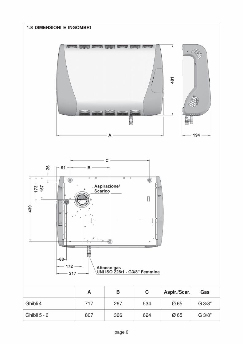
1.8 DIMENSIONI E INGOMBRI
A B C Aspir./Scar. Gas
Ghibli 4 717 267 534 Ø 65 G 3/8"
Ghibli 5 - 6 807 366 624 Ø 65 G 3/8"
Fig. 1

page 7
1.9 WIRING DIAGRAM - Ghibli Model 4
Fig. 2
Al = External auxiliaries supplyAc = Control equipmentEa = Ignition electrodeEr = Flame detection electrodeEv = Gas solenoid valveFr = RFI filterInt = On-Off switchM1-2-3 = Connection terminal boardsMe = Flue gas exhaust motorMv = Fan motorOp = Bridge for auxiliaries (i.e.: timer)R = Reset buttonSb = Lockout signalSrc = Heat request signalT = Earth connectionTa = Room thermostatTs = Safety thermostatTv = Fan thermostat
= Fuse, 2A- - - - - = Connection to be made
= Series connection
Warning:- Power should be supplied to the heater
via a switch with contact opening of atleast 3 mm.
- Observe the correct phase-neutral polaritywhen connecting the single-phase, 230 V~ 50 Hz power supply.
Me
N
L
Ts
Op
Mv
Ta
Tv
Ev
Ea
Er
Ac Src
Int
R
Sb
Fr
M2
M1
17
16
15
14
13
12
11
10
9
N
L
230 V ~
50 Hz
8
7
6
5
4
3
2
1
18
19
M3
Al
T
1.9 WIRING DIAGRAM - Ghibli Model 5
Fig. 3
Al = External auxiliaries supplyAc = Control equipmentCo = Fan speed switchEa = Ignition electrodeEr = Flame detection electrodeEv = Gas solenoid valveFr = RFI filterInt = On-Off switchM1-2-3 = Connection terminal boardsMe = Flue gas exhaust motorMv = Fan motorOp = Bridge for auxiliaries (i.e.: timer)R = Reset buttonSb = Lockout signalSrc = Heat request signalT = Earth connectionTa = Room thermostatTs = Safety thermostatTv = Fan thermostat
= Fuse, 2A- - - - - = Connection to be made
= Series connectionWarning:
- Power should be supplied to the heater via aswitch with contact opening of at least 3 mm.
- Observe the correct phase-neutral polaritywhen connecting the single-phase, 230 V ~50 Hz power supply.
N
L
Ts
Op
Mv
Ta
Tv
Ev
Ea
Er
Ac Src
Int
R
Sb
Fr
M2
M1
17
16
15
14
13
12
11
10
9
N
L
230 V~ 50 Hz
8
7
6
5
4
3
2
1
18
19
M3
Al
T
Co
common
I
II
Me
Fan motor 2 speed 3 speedconnections motor motorMax. speed II
Med. speed IIMin. speed I I

page 8
1.9 WIRING DIAGRAM - Ghibli Model 6
Fig. 4
N
L
Ts
Op
Mv
Ta
Tv
Ev
Ea
Er
Ac Src
Int
R
Sb
Fr
M2
M1
17
16
15
14
13
12
11
10
9
N
L
230 V
~ 50 Hz
8
7
6
5
4
3
2
1
18
19
M3
Al
T
Co
common
I
II
Me
Al = External auxiliaries supplyAc = Control equipmentCo = Fan speed switchEa = Ignition electrodeEr = Flame detection electrodeEv = Gas solenoid valveFr = RFI filterInt = On-Off switchM1-2-3 = Connection terminal boardsMe = Flue gas exhaust motorMv = Fan motorOp = Bridge for auxiliaries (i.e.: timer)R = Reset buttonSb = Lockout signalSrc = Heat request signalT = Earth connectionTa = Room thermostatTs = Safety thermostatTv = Fan thermostat
= Fuse, 2A- - - - - = Connection to be made
= Series connectionWarning:- Power should be supplied to the heater
via a switch with contact opening of atleast 3 mm.
- Observe the correct phase-neutral polaritywhen connecting the single-phase, 230 V~ 50 Hz power supply.
1.10 TECHNICAL DATA TABLE Units Ghibli 4 Ghibli 5 Ghibli 6
Heat input (Hi) kW 3,72 4,83 5,52
kcal/h 3.200 4.150 4.750
Heat output (Hi) kW 3,35 4,37 4,91
kcal/h 2.880 3.760 4.220
Gas Natural gas G20 mc/h 0,39 0,51 0,58
consumption Butane G30 kg/h 0,29 0,38 0,44
(15 °C - 1.013 mbar) Propane G31 kg/h 0,29 0,37 0,43
Burner G20 p 20 mbar mbar 11,5 11,5 11,5
pressure G30 p 28-30 mbar mbar 27,8-29,8 27,7-29,8 27,7-29,8
(15 °C - 1.013 mbar) G31 p 37 mbar mbar 36,5 36,5 36,5
Injector size G20 mm 1,70 1,90 2,05
G30 / G31 mm 1,00 1,10 1,15
Air delivery Min. speed m3/h 110 180 240
Max. speed m3/h - 240 300
Gas service connection “ G 3/8
Air supply / Flue exhaust diameter mm 65
Fuse A 2
Electrical supply 230 V ~ / 1 / 50 Hz
Electric power W 47 80 102
Net weight kg 21 27 27

page 9
1.1
1
EX
PL
OD
ED
VIE
W -
Mo
del
Gh
ibli 4
Fig
. 5

page 10
1.1
1 E
XP
LO
DE
D V
IEW
- M
od
els
Gh
ibli 5
an
d 6
Fig
. 6

page 11
Legend of components Ghibli 4 (see fig. 5)
Pos Codice ......................................................... Description
01 45610001 ........................................ Casing Ghibli 5/6 Elite
02 45810002 .................................... Screw for casing fixing
04 45610004 ................................... Heat exchanger Ghibli 4
05 40170018 .................................................. Fan thermostat
07 45610008 .................................................. Burner Ghibli 4
08 45610009 ............................................. Burner Disk Ghibli
10 45960007 ................................ Flame detection electrode
11 45960008 ............................................... Ignition electrode
11 45610012 ....................................... Gas injector MET 1.70
12 45610313 ....................................... Gas injector LPG 0.95
14 45610014 .................................... Burner chamber gasket
15 45970012 ...................................... Knob room thermostat
16 45620015 .............................. Commands electrical board
18 45620017 ..................... Electric supply connection board
19 45810021 .............................................................. Gas tap
20 45960033 .......................................................... Gas valve
21 45960034 ........................................ Valve rectifier bridge
22 45960035 ................................................ Spool gas valve
23 45970020 ............................................... Room thermostat
25 45960216 ........................................................ Control box
27 45620026 ........................................ Flue gas exhaust fan
28 45610032 ........................... Exchanger/exhauster gasket
30 45610034 ..................................... Intake/exhaust terminal
31 45610035 .......................................... Intake/exhaust duct
32 45610036 .................................... Duct attachment gasket
33 45610037 .................................................... Tangential fan
34 45880506 ................................................ Tank of humidity
35 45880501 ................................. Plastic side dx Ghibli elite
36 45880502 ................................. Plastic side sx Ghibli elite
37 45610003 ............................................. Safety thermostat
38 45650211 .................................... Plate side dx Ghibli elite
39 45650212 .................................... Plate side sx Ghibli elite
40 45880503 ........................... Fixing plate side A Ghibli elite
41 45880504 ........................... Fixing plate side B Ghibli elite
42 45652522 ............................... Gas valve plate Ghibli elite
43 45652523 ....................... Plate for control box Ghibli elite
44 45880505 ..................................... Door control Ghibli elite
45 45611601 ................................................ Gas supply pipe
47 45970011 ........................... Internal electric wiring board
48 45619501 ..... Stricker plate of control panel Ghibli 4 elite
(*) Components missing in the design
* 45610038 ..................................... Bronze friction bearing
* 45960036 ............................. Kit of gas valve connection
Legend of components Ghibli 5 and 6 (see fig.6)
Pos Code description
01 45660001 ........................................ Casing Ghibli 5/6 Elite
02 45810002 .................................... Screw for casing fixing
04 45710004 ........................ Heat exchanger Ghibli 5/6 Elite
05 40170018 .................................................. Fan thermostat
07 45660008 ............................... Complete burner Ghibli 5/6
08 45710009 ....................................... Burner Disk Ghibli 5/6
10 45960007 ................................ Flame detection electrode
11 45960008 ............................................... Ignition electrode
12 45660013 ....................................... Gas injector MET 1.90
13 45660014 ....................................... Gas injector GPL 1.10
14 45610014 .................................... Burner chamber gasket
15 45970012 ...................................... Knob room thermostat
16 45670016 .............................. Commands electrical board
18 45620017 ..................... Electric supply connection board
19 45810021 .............................................................. Gas tap
20 45960033 .......................................................... Gas valve
21 45960034 ........................................ Valve rectifier bridge
22 45960035 ................................................ Spool gas valve
23 45970020 ............................................... Room thermostat
25 45960216 ........................................................ Control box
27 45670027 ........................................ Flue gas exhaust fan
28 45610032 ........................... Exchanger/exhauster gasket
30 45610034 ..................................... Intake/exhaust terminal
31 45610035 .......................................... Intake/exhaust duct
32 45610036 .................................... Duct attachment gasket
33 45710039 .................................................. Centrifugal fan
34 45880506 ................................................ Tank of humidity
35 45880501 ................................. Plastic side dx Ghibli elite
36 45880502 ................................. Plastic side sx Ghibli elite
37 45610003 ............................................. Safety thermostat
38 45650211 .................................... Plate side dx Ghibli elite
39 45650212 .................................... Plate side sx Ghibli elite
40 45880503 ........................... Fixing plate side A Ghibli elite
41 45880504 ........................... Fixing plate side B Ghibli elite
43 45652523 ....................... Plate for control box Ghibli elite
44 45880505 ..................................... Door control Ghibli elite
45 45611601 ................................................ Gas supply pipe
47 45970011 ........................... Internal electric wiring board
48 45719501 ..... Stricker plate of control panel Ghibli 4 elite
(*) Components missing in the design
* 45960036 ............................. Kit of gas valve connection
* 45652522 ............................... Gas valve plate Ghibli elite

page 12
2. CONTROL AND SAFETY DEVICES
2.1 GAS CONTROLLER
This device is housed in a heat-resistant andshockproof plastic enclosure and is mounted onthe air heater electric board (fig. 7).The control device operates on the ionisationflame detection principle, using a special probeon the burner.
The detection circuit must be fed with single-
phase 230 V ~ 50 Hz mains voltage. The
circuit is sensitive to the phase-neutral
polarity. If this is reversed, the device will
lock out within the safety time, even if the
flame has a regular shape (for special cases
consult our Technical Office).
2.2 GAS VALVE
The gas valve includes two, direct operationsolenoid valves with class B closing devices(maximum pressure 50 mbar) and a pressureregulator. The die-cast aluminium casing isequipped with 3/8 RP threaded gas inlet andoutlet connections and two inlet and outletpressure test points. The gas valve is alsoequipped with an inlet filter (fig. 22).
2.3 FAN THERMOSTAT
This thermostat controls fan operation, makingit start when the exchanger has reached therated operating temperature and stopping itwhen the exchanger has adequately cooled.The thermostat is attached to a threaded support,located on the exchanger (fig. 8).
2.4 SAFETY THERMOSTAT
The thermostat is designed to interrupt burneroperation when the air temperature in the airheater reaches a set value, i.e. when theexchanger overheats due to insufficient air flowor a fan malfunction. The thermostat enclosureuses a special support to attach to the frontshield of the appliance (fig. 9).
Fig. 7
GAS CONTROLLER
Fig. 9
SAFETY THERMOSTAT
Thermostat
Electricconnection
Fig. 8
FAN THERMOSTAT
Threaded attachment
Electric connection

page 13
SECTION 2TECHNICAL INFORMATION FOR THE INSTALLER
3. PRECAUTIONS
3.1 GAS SAFETY REGULATIONS
The law requires all gas appliances to be
installed by competent persons in accordance
with the regulations. Failure to install
appliances correctly may lead to prosecution.
It is in your own interests and that of safety to
ensure compliance with the law.
3.2 RELATED DOCUMENTS
Notwithstanding their limited scope, the appliancesshould be installed in accordance with the relevantprovisions of the following regulations:
UNITED KINGDOMGas Safety (Installation and Use) Regulations1984 and BS 6891: 1988. Due account shouldbe taken of any obligations arising from theHealth and Safety at Work etc Act 1974, thecurrent Building Regulations, the current I.E.E.Regulations and other relevant codes of practice.
IRELANDI.S.3212: 1987, ICP 4, I.S.327. Due accountshould be taken of any obligations arising fromthe current Building Regulations, the current I.E.E.Regulations and other relevant codes of practice.
3.3 TRANSPORT AND HANDLING
The air heater is supplied with standard cardboardpacking with two polystyrene foam shells. Thepacked appliance can be handled by hand orwith a fork-lift truck, making sure to observe theinstructions reported on the box indicated by thespecial graphic symbols.
When delivered, check that no visible damageon the packing and/or on the appliance hasoccurred during transport. If damage is noted,immediately submit a claim to the shipping agent.
When removing the air heater from the packing,do not damage the cardboard. The assemblytemplate to be used to make the holes on the wallin the room is printed on that cardboard. Checkthat the packing includes the appliance but alsoall the parts indicated in point 1.5. Place thematerial and the documents in a protected area.
3.4 DATA CHECK
Check that the heater and its technicalcharacteristics match what is indicated by thedrawings or other documents.
The type of gas for which the heater has been
designed and the supply pressure are found
on the exterior of the packing and on a special
label located on the inside of the appliance.
WARNING! If the type gas for which the
appliance has been designed is different
from the one being used, the conversion
operation must be carried out by skilled
technical personnel.
3.5 USING THE INSTRUCTIONS
WARNING! When installing or working on
the appliance, comply with all the instructions
given in this manual. Changes to any type of
connection and non-compliance with these
instructions will immediately invalidate the
warranty and release the manufacturer from
all responsibilities.
4. INSTALLATION
4.1 POSITIONING INSTRUCTIONS
Before carrying out any installation operations,make sure that the following conditions aresatisfied regarding the position where the airheater will be installed:
a) the appliance with standard accessories ,must be installed on an external wall to ensurethat the it operates correctly.
The appliance can also be installed on otherwalls by using a special kit which splits theflue from the air intake. This is known as adoubling device (see point 4.2.1).
b) it must be possible to provide a gas supply tothe selected point as well as a single-phase230 Volts ~ 50 Hz power supply line
c) the position must be suitable to distribute theair correctly into the room and the air flowshould not be obstructed by obstacles suchas furniture or drapes
d) the appliance must be installed at a minimumof 10 cm from the floord so that the convectionfan can take in air correctly and thus ensureoptimal circulation of air on the exchanger. Donot install the base of the appliance at a heightof more than 50 cm from the floor, since thiswould lead to a non-uniform distribution of thewarm air and thus waste fuel

page 14
e) if the appliance is installed under a window orunder a shelf, make sure that the sill or theshelf does not obstruct the flow of warm air;it is recommended that a distance of at least20 cm is maintained. For this reason and tomake maintenance easier, the air heatershould not be installed inside niches or inpositions where it is difficult to access. Theclearances indicated in fig. 11 should beobserved.
4.2 AIR INTAKE AND FLUE EXHAUST DUCTS
WARNING! The material used to build the
external wall and any covering (wood, plastic)
must not be sensitive to the heat generated
by the flue gas exhaust duct. If it is heat
sensitive, the passage hole must be
protected with insulation that insulates the
wall or the covering.
4.2.1 Type definition
As already mentioned in point 1.1, the Ghibli airheater can be installed with different configurationsof the air intake and combustion product exhaustduct(s) and these different solutions constitutethe definition of "type" according to the currentstandards:
- Type C12
(standard supply)
The combustion circuit is hermetically sealedwith respect to the environment in which the airheater is installed. The intake/exhaust ductpasses directly through the external wall of theroom. This is the standard configuration supplied(fig. 12).
- Typr C52
(with accessories on request)
The combustion circuit is sealed with respect tothe environment in which the air heater is installed.The ducts are separated and both are connectedto the outdoors, but their terminals need not beadjacent to each other (fig. 13).
WARNING! Also in the second solution (Type
C52
), the intake and exhaust ducts, including
the relative accessories, are considered by
the standards to be integral parts of the air
heater. Therefore, they must be requested
from the manufacturer.
In both the cases described above the length ofthe ducts must always respect the limits indicatedin the next point.
Fig. 12
TYPE C12
INSTALLATION(standard supply)
Air intake / flue gasexhaust duct
External terminal
Fig. 10
POSIZIONAMENTO
10-15 cm
min. 20 cm
MINIMUM MAINTENANCE DISTANCES
Fig. 11
TOP VIEW
60 cm 30 cm

page 15
4.2.2 Duct length limits
If the duct passes directly through the externalwall, and if that wall has a thickness of more than40 cm, an intake/exhaust duct with a length of 1metre can be supplied on request. If the applianceis installed with separated ducts, using the specialaccessory, the length of the ducts must not begreater than 6 metres, considered as the sum ofthe layout of both ducts (for example: 3 m intake+ 3 m exhaust, etc.), to ensure correct operation.
It should be remembered that a bend isequivalent to a straight segment of about 50 cm.If the exhaust duct layout is exposed to lowtemperatures, prevent condensation fromforming by using suitable insulation on that duct.
4.3 OUTSIDE POSITIONING OF THE FLUE
GAS EXHAUST TERMINAL
The position of the flue gas exhaust terminal andits distance from windows, ventilation openings,etc. must comply with what is prescribed by thecurrent standards.
If the air heater is installed in rooms on the groundfloor and the exhaust faces sidewalks at the levelof pedestrians, a special protection grille must beapplied, which is supplied on request (fig. 14).
4.4 INSTALLATION OPERATIONS
Set up the gas and electricity supply lines basedon the installation design.
4.4.1 Air heater wall-mounting preparations
(appliance with standard supply -
Installation Type C12
)
Once the position and the height of the appliancefrom the ground has been determined, use the
wall template from the cardboard packing toindicate the positions of the holes to be made(three holes to attach the appliance with an Ø 8mm bit for expansion bolts, one hole for theintake/exhaust duct with special hole cutter Ø 70mm, to be made as perpendicular as possible tothe direction of the wall).
The template also indicates the positions of theelectric power supply cable and gas feeder pipeentries.
4.4.2 Mounting the intake/exhaust duct
(appliance with standard supply -
Installation Type C12
)
The intake/exhaust duct, supplied for walls up to40 cm, consists of an aluminium pipe withconnector flange and an external terminal. Mountthe duct in the sequence described below:
Fig. 14
TERMINAL PROTECTION GRILLE
Grille
TYPE C52
INSTALLATION
Fig. 13SIDE VIEW
TOP VIEW
Using the doubling device (supplied onrequest), it is possible to create differentconfigurations of the air intake and flue gasexhaust ducts, within specified limits. Theexternal terminals are not required to beadjacent to each other.

page 16
a) precisely measure the thickness of the wall.This measurement corresponds to thedistance between the flange and the point inwhich the duct must be cut (fig. 15)
b) use a hack saw to cut the aluminium duct tothe specific measurement. Trim off any burrsusing a file
c) insert the duct into the appliance using thespecial gasket and tighten it with the threescrews supplied with the kit.
WARNING! The duct can only be connected
in one direction; do not force the pipe if
resistance is felt. Note the position of the
pipe on the flange and turn it in the correctposition, if necessary.
4.4.3 Air heater wall-mounting preparations
and duct installation (appliance with
accessories for separate intake and
exhaust ducts - Installation Type C52
)
Unlike the previous solution, to mount the ductdoubling device a recessed housing must becreated in the wall and possibly some chases toindicate the duct layout (fig. 16).
Therefore, by positioning the cardboard template,the centre of the appliance intake/exhaust fittingmust be traced on the wall. The centre of thesimilar doubling device fitting must be in thesame position.
Create the depression in the wall for the doublingdevice and make the necessary chases to housethe ducts, whether or not they are the rigid or the
Fig. 15
INTAKE / EXHAUST DUCT(Type C
12 - standard supply)
Terminal
Air intake and fluegas exhaust duct
Wall thickness
Attachmentscrew
Fig. 17
LOCATION OF THE DOUBLING DEVICEIN THE WALL (top view)
WARNING!(Side flush with wall)
Fig. 18
COUPLING WITH THE DOUBLING DEVICE
Aluminiumflange
O-Ring gasket
ScrewDoubling device
Fig. 16
SOLUTION WITH DUCT DOUBLING DEVICE
FLUE GAS
AIR INLET

page 17
bendable type in stainless steel. Connect theducts to the doubling device using metal clampsand tighten them to ensure a good seal on thefitting. With the doubling device connected inthis manner, place it in the housing and block itinto position using cement mortar.
Make sure to respect the position indicated
in fig. 17, so that only the circular fitting
projects from the finished wall, while the
interior of the doubling device is flush with
that wall.
WARNING! The seal of the connector between
the doubling device and the appliance is
created by a special gasket (fig. 18). Make
sure that the wall on which the air heater is
installed is perfectly flat, so that the
subsequent attachment of the appliance does
not change the coupling.
Assemble the ducts in the chases up to therelative external terminal, carefully checking anyjoints (if a rigid tube is used make sure that thespecial unions and gaskets are mountedcorrectly).
WARNING! It is recommended to insulate the
duct by using insulating material that is
suitable for the temperatures generated (for
example, glass fibre mattress for temperatures
up to 200°C), to prevent condensation from
forming inside the duct and/or to avoid cracks
in the plaster due to the high temperature. At
the end of the previous operations close the
chases, making sure that the cement mortar
completely covers the ducts and that there
are no empty spaces.
Place the previously used template on the wall,centering the position of the intake/exhaust fittingonto the corresponding centre of the walleddoubling device, and mark the position of thethree holes to attach the appliance. The holesshould be drilled using an Ø 8 mm bit forexpansion bolts.
To adapt the intake/exhaust fitting of theappliance to the coupling with the doubling deviceconnector, do the following operations:
a) remove the three screws inserted in the fittingon the appliance (they will not be used again)
b) mount the aluminium flange Ø 92 mm,inserting the ring gasket and attaching it onthe appliance fitting using the three screwssupplied with the kit. Check that the ringgasket fits correctly into its housing (fig. 18).
4.4.4 Appliance wall mounting
a) Appliance with standard supply -
Installation Type C12
Lift the appliance and, putting the intake/exhaustduct at the beginning of the hole, push it towardthe wall until contact is made.
Adjust the position of the appliance and attachit with the expansion screws that werepreviously inserted into the wall. On theexterior, check that the intake/exhaust ductends flush with the wall.
Insert the external wind protection terminal onthe duct and mark the position of the hole forthe expansion bolt to be drilled in the wall (fig.
15). After drilling the hole, re-insert the terminaland attach it permanently, checking its stability.
b)Appliance with accessories for separate
intake and exhaust ducts - Installation
Type C52
Lift the air heater and slowly bring it closer tothe wall until coupling the two intake/exhaustconnectors located on the doubling deviceand on the appliance.
Making sure not to change the couplingdescribed above, adjust the position of theappliance and attach it using the expansionscrews that were previously inserted intothe wall.
In both cases described above, it is
recommended to use two persons to lift and
position the air heater to avoid any possibledamage to the wall or the appliance.
4.4.5 Gas connection
Mount the gas on-off valve supplied with theappliance using the special gasket. Connect thegas supply line to the valve which is equippedwith a female threaded attachment G 3/8".
WARNING!: The valve must be located in aposition that can be easily accessed by the
user.
Check the seal on the gas piping and make surethat it was created in conformity with the currentstandards regarding gas installations.
4.4.6 Electrical connections
Ensure that a single-phase, 230 V ~ 50 Hzelectric power supply is available.
The appliance must be properly insolated bymeans of an omnipolar circuit-breaker with

page 18
an adequate rating to be used as a general
switch to turn off the appliance(s).
Connect the power supply cable to the phase,neutral terminals and to the earth connection ofthe appliance. Insert the power supply cablethrough the special cable gland, making sure tocut the wires so that the yellow/green earth cableis slightly longer than the other two.
This precaution, in case of accidentaldetachment, allows the earth cable to be the lastconnection to be removed (fig. 19).
Comply with the phase/neutral polarity,
otherwise the control equipment will gene-
rate a safety lock out.
THESE APPLIANCES MUST BE EARTHED.
4.4.7 Using a timer (the kit is supplied on
request)
To operate the air heater automatically atpredetermined hours, it is possible to install adigital timer on the appliance, even after theappliance has already been installed. The timeris supplied on request as an assembly kit.
4.4.8 Connecting more than one unit with a
single external timer
To operate several appliances with just onetimer follow the diagram given in fig. 20 to avoidmalfunctions of the entire installation.
To complete this special connection, use anormally open contact relay with an adequaterating. Terminals 3 and 4 will be connected to theterminal board of the appliances, after havingremoved the existing bridge.
5. START-UP
WARNING! The appliance initial start-up
operations and tests must be performed by
skilled technical personnel.
5.1 TESTS
5.1.1 Before starting the air heater, make surethat all the current provisions and standardsrelevant to the installation of these applianceshave been observed. Pay particular attention tothe correct positioning of the combustionproduct exhaust terminal.
5.1.2 Make sure that the single-phase, 230 V ~50 Hz electric power supply and the earth wireare connected to the special air heater terminals.The phase conductor must be connected to theterminal marked with the letter "L", otherwise thecontrol equipment will generate a safety lockout.
5.1.3 Check that the gas injector mounted onthe burner corresponds to what is indicated forthe type of gas to be used (table on page 11).
WARNING! The appliance are delivered
already set in the factory to use natural gasG20, with a supply pressure of 20 mbar.
Instead, if gas from the third group is used
(G30 - G31), first carry out the operations
described in point 6.1.
5.1.4 Check that the gas on-off valves on themeter and on the air heater are open. Make surethat the air inside the gas supply piping has beenpurged.
Fig. 20
4
3
1st heater 2nd heater4
3
nth heater
n
2
1
n
2
1
Relaywith n
contacts
timerswitch
Neutral
Phase
4
3
Fig. 19
POWER SUPPLY CABLE CONNECTION
Brown
Yellow / Green
Blue

page 19
been purged and the ignition is regular.
The exchanger heating phase begins after theburner has been ignited. The exchanger reachesthe rated operating temperature after about threeminutes and at that point a thermostat starts thefan to distribute warm air in the environment.
5.2.2 Controls
WARNING! When operations or visual
inspections are performed on the air heater,
be extremely cautious and work under safe
conditions.
Insert the water column pressure gauge tubeinto the pressure outlet on the gas unit (fig. 22)after having backed off the screw a few turns.Start the air heater and check that the pressureto the burner corresponds to what is indicated inthe technical data table.
If the pressure of the gas delivered to the burnerdoes not correspond to the value indicated, usethe special pressure set screw (fig. 22), afterhaving removed the protection plug, to obtainthe specified value. Turn it counterclockwise todecrease the pressure and clockwise to increasethe pressure (this operation can be carried outonly when using natural gas G20).
Turn the room thermostat dial to the minimumvalue and check that the burner shuts off.
Remove the pressure gauge tube and tightenthe pressure regulator screw, carefully checkingthe seal. Replace the regulator protection plug.
WARNING! When the burner turns off, thefan(s) will continue to operate for a few
minutes, to properly cool the exchanger.Therefore, it is important not to turn off the
air heater using the mains switch, that alsocuts off the power supply to the fan(s), since
this might lead to overheating and trip the
safety thermostat.
Then repeat the start-up operation to observeand check that the burner has ignited correctlyand that the flame is stable.
5.3 USEFUL INFORMATION
It is recommended that the user be informed
about all the operations necessary to use the
air heater correctly, with particular referenceto the ignition and shutdown phases and
about the importance of periodic tests, which
must be performed at least once every yearby skilled personnel.
5.2 IGNITION
5.2.1 Ignition procedure
(Refer to fig. 21 when reading the following
section )
a) Place switch (A) in the on position "I" to startthe ignition cycle. If the digital timer has beeninstalled, refer to the instructions for thatdevice to perform the additional operations.
b) Turn the room thermostat dial (D) clockwiseto the highest value. This marks the beginningof the start-up phase, indicated when thegreen led (E) turns on.
c) Check that the red led (F) is turned off. If it ison, this means that the burner controlequipment is in the "lockout" position. In thiscase, press the button (C) to reset the controlequipment, and the red light will turn off.
After completing the pre-purge phase (afterabout 30 seconds), the system simultaneouslyopens the gas solenoid valve and activates thetransformer to discharge the electrode to ignitethe burner.
From the moment in which the burner is ignited,the flame must be detected by the specialionisation sensor within the specific safety time,otherwise the control equipment enters the lockout mode, indicated when the red led (F).
This may occur in particular in a new plant dueto air in the gas piping. In this case, wait aboutone minute and reset the appliance by pressingthe "reset" button (C) to begin a new cycle.
Repeat the operation until the residual air has
Fig. 21
CONTROL PANEL

page 20
6. GAS TYPE CHANGE
WARNING! The operations described below
must be carried out by skilled technical
personnel.
6.1 SWITCHING FROM GAS IN THE SECOND
GROUP (G20) TO GAS IN THE THIRD
GROUP (G30 - G31)
a) Check that the envelope supplied with the airheater contains the replacement injector, thescrew block with pin and the adhesive label,on which to indicate the new type of gas beingused, to replace the original one
b) check that the diameter of the injectorindicated for the type of gas to be used (see
technical data table on page 11) correspondsto what is stamped on the injector.
c) close the gas on-off valve and disconnect theelectric power supply. Remove the air heatercasing using the two screws located at thebottom and the two screws at the top, whichcan be accessed by using the screwdriversupplied with the kit
d) remove the 6 screws which attach the burnersupport plate to the combustion chamber.Pull it out making sure not to damage the sealgasket. Disassemble the gas injector using a10 mm hex wrench and replace it with the newone, then re-tighten it to ensure a proper seal(fig. 23)
e) replace the burner support plate making surethat the gasket is in the correct position.Attach the plate using the 6 screws that werepreviously removed
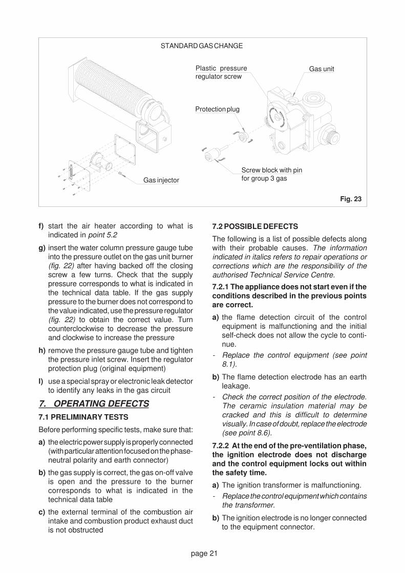
f) unscrew the pressure regulator protection pluglocated on the gas unit. With care, fully tightenthe plastic screw of the pressure regulator.Insert the screw block with pin instead of theprotection plug to put the regulator out ofservice (fig. 23). Keep the pressure regulator
protection plug for future use
g) insert the water column pressure gauge tubeinto the upstream pressure inlet on the burner(fig. 22) after having backed off the closingscrew a few turns
h) start the air heater according to what isindicated in point 5.2. Check that the supplypressure corresponds to what is indicated inthe technical data table. If the gas supplypressure does not correspond to the valueindicated, use the pressure regulator (secondstage) installed externally to obtain the correctvalue
i) remove the pressure gauge tube and tightenthe pressure inlet screw
l) use a special spray or electronic leak detectorto identify any leaks in the gas circuit
m)replace the air heater casing and attach it atthe four special points.
6.2 SWITCHING FROM GAS IN THE THIRD
GROUP (G30 - G31) TO GAS IN THE
SECOND GROUP (G20)
a) check that the adaptation kit envelope containsthe replacement injector and the adhesivelabel, on which to indicate the new type of gasbeing used, to replace the original one
b) close the gas on-off valve and disconnect theelectric power supply. Remove the air heatercasing using the two screws located at thebottom and the two screws at the top, whichcan be accessed by using the screwdriversupplied with the kit
c) remove the 6 screws which attach the burnersupport plate to the combustion chamber.Pull it out making sure not to damage the sealgasket. Disassemble the gas injector using a10 mm hex wrench and replace it with the newone, then re-tighten it to ensure a proper seal(fig. 23)
d) replace the burner support plate making surethat the gasket is in the correct position.Attach the plate using the 6 screws that werepreviously removed
e) on the gas unit, remove the screw block withpin located on the pressure regulator to resetregulation operation (fig. 23)
Fig. 22
GAS UNIT
Electricconnection
Pressure set screw
Gas
Pressure outlet
Pressure inlet
page 21
f) start the air heater according to what isindicated in point 5.2
g) insert the water column pressure gauge tubeinto the pressure outlet on the gas unit burner(fig. 22) after having backed off the closingscrew a few turns. Check that the supplypressure corresponds to what is indicated inthe technical data table. If the gas supplypressure to the burner does not correspond tothe value indicated, use the pressure regulator(fig. 22) to obtain the correct value. Turncounterclockwise to decrease the pressureand clockwise to increase the pressure
h) remove the pressure gauge tube and tightenthe pressure inlet screw. Insert the regulatorprotection plug (original equipment)
l) use a special spray or electronic leak detectorto identify any leaks in the gas circuit
7. OPERATING DEFECTS
7.1 PRELIMINARY TESTS
Before performing specific tests, make sure that:
a) the electric power supply is properly connected(with particular attention focused on the phase-neutral polarity and earth connector)
b) the gas supply is correct, the gas on-off valveis open and the pressure to the burnercorresponds to what is indicated in thetechnical data table
c) the external terminal of the combustion airintake and combustion product exhaust ductis not obstructed
7.2 POSSIBLE DEFECTS
The following is a list of possible defects alongwith their probable causes. The information
indicated in italics refers to repair operations or
corrections which are the responsibility of the
authorised Technical Service Centre.
7.2.1 The appliance does not start even if the
conditions described in the previous points
are correct.
a) the flame detection circuit of the controlequipment is malfunctioning and the initialself-check does not allow the cycle to conti-nue.
- Replace the control equipment (see point
8.1).
b) The flame detection electrode has an earthleakage.
- Check the correct position of the electrode.
The ceramic insulation material may be
cracked and this is difficult to determine
visually. In case of doubt, replace the electrode
(see point 8.6).
7.2.2 At the end of the pre-ventilation phase,
the ignition electrode does not discharge
and the control equipment locks out within
the safety time.
a) The ignition transformer is malfunctioning.
- Replace the control equipment which contains
the transformer.
b) The ignition electrode is no longer connectedto the equipment connector.
STANDARD GAS CHANGE
Fig. 23
Gas injector
Plastic pressureregulator screw
Protection plug
Screw block with pinfor group 3 gas
Gas unit

page 22
- Restore the connection or replace the
electrode including the cable. Do not make
joints to avoid reducing the cable insulation
level.
c) The ignition electrode is not correctlypositioned or its ceramic insulation isdamaged, with a subsequent leakage of theignition discharge.
- Replace the electrode including the cable.
7.2.3 At the end of the pre-ventilation phase,
the ignition electrode discharges, but the
flame is not formed and the control equipment
locks out within the safety time.
a) No gas supply or there is air inside the piping.
- Determine why there is no gas supply first
checking the on-off components on the feed
line. Completely bleed off any residual air and
restart the appliance.
b) The gas solenoid valves do not open becausethe coils are malfunctioning or their electricalconnection has been interrupted.
- Check if the connection cable and relative
terminals have been damaged. Use a special
tool to verify that the coils have failed and
replace them, if necessary (see point 8.3).
c) The safety thermostat is malfunctioning anddoes not allow the solenoid valves to open.
- Replace the safety thermostat (see point 8.5).
7.2.4 At the end of the pre-ventilation phase,
the ignition electrode discharges, the flame
is formed correctly, but the control equipment
locks out within the safety time.
a) The phase-neutral electric power supply isnot correctly connected to the respectiveterminals, marked as "L" and "N" and reversingthe polarity may de-activate the flamedetection device.
- Check using a multimeter or phase detector
and correctly connect the cables to the
corresponding terminals.
b) The flame detection electrode is not correctlypositioned and is not in contact with the flame.
- Check if the electrode is properly connected
and if there are any deformations. Comply
with what is indicated in figure 28.
c) The flame detection electrode electricconnection has been interrupted.
- Check the electrode connection to the control
equipment. If the cable or ceramic insulation
is damaged, replace the electrode in
accordance with the positions indicated in
figure 28.
d) The flue gas exhaust fan motor is malfunctioningor does not operate correctly because theintake/exhaust duct is obstructed.
- First eliminate any obstructions in the terminal
and, if necessary, replace the fan, making
sure to re-assemble the unit as shown in fig.
29 (see point 8.8)
7.2.5 The control equipment locks out during
normal operation
a) The gas supply was cut off and the equipment,after repeating the ignition cycle, and withoutdetecting the flame within the safety timeperiod, entered the lock out mode.
- Determine why the gas supply prior to the air
heater was interrupted. Restart the appliance
using the Reset button on the control panel.
b) The incorrect positioning of the external intakeand exhaust terminal has caused combustionproducts to return and this prevents the flamefrom being formed and therefore from beingdetected by the electrode.
- Check that the terminal is not installed inside
niches or recesses in the walls and that there
are no obstructions that prevent the air from
circulating.
c) The safety thermostat cuts off the supply tothe gas solenoid valve because overheatinghas occurred due to incorrect operation or afailure of the convection fan.
- Check for obstructions or dust deposits on
the fan and/or relative grille. Replace the
malfunctioning fan, if necessary (see point
8.8).
d) The safety thermostat cuts off the supply tothe gas solenoid valve because overheatinghas occurred due to incorrect operation of thefan control thermostat.
- Replace the fan control thermostat (see point
8.4).
7.2.6 The burner stops while it is operating,
even if the room temperature does not
require it
a) The room thermostat is defective.
- First check that the thermostat sensor is in
the correct position and that its operation has
not been affected by dust deposits. Otherwise,
replace the defective room thermostat.

page 23
8. REPLACING PARTS
Since specific technical skills are required
to replace the parts listed below, it is
recommended to advise the user to always
contact skilled technical personnel. For safety
and quality reasons, it is recommended to
use original spare parts when replacing
components.
WARNING! All the following operations must
be carried out while the heater is turned off,
disconnecting the gas and electric supplies.
8.1 CONTROL EQUIPMENT
Disconnect the cables by pulling on the terminalsand extracting the connectors, releasing themfirst from the special retainer. Replace theequipment, placing it in the special insert andattaching it using the self-threading screw. Insertthe terminals and the connectors into theirrespective housings (fig. 24).
8.2 FUSE
Using a special tool, remove the fuse holder on thepower supply terminal board. Replace it with a newfuse (5x20 -2 Amps - instantaneous type) byexerting slight pressure until it enters the housing.Replace the fuse cap in the terminal board.
8.3 GAS SOLENOID VALVES
Disconnect the electric connection on the gasunit. Remove the two screws that attach themetal support block of the coils and remove itfrom the housing. Pull out the coil(s) from the unitand replace them with new ones. Replace themetal support block in the correct position andtighten the fastening screws. Re-establish theelectrical connection (fig. 25).
8.4 CONVECTION FAN CONTROL THERMOSTAT
Disconnect the cables and unscrew thethermostat from the threaded support. Insert thenew thermostat, screwing it all the way in byhand (do not use tools which might damage thethermostat). Make sure that the distance betweenthe thermostat enclosure and the threadedsupport is not greater than 3 mm, to guaranteethat the sensor remains in contact with the wallof the exchanger. Re-establish the electricalconnection (fig. 26).
8.5 SAFETY LIMIT THERMOSTAT
Disconnect the electric connection of thethermostat on the appliance terminal board.Release the thermostat by disassembling theattachment plate on the air heater shield. Mountthe new thermostat by reversing the order of the
Fig. 24
CONTROL EQUIPMENT REPLACEMENT
Equipment enclosure
Connectorsand terminals forelectrical connections Fig. 26
FAN THERMOSTAT REPLACEMENT
Thermostat
Exchanger
Threadedsupport
Unscrew
Fig. 25
GAS UNIT COIL REPLACEMENT
Coil support
Gas unit
Fastening screws
Solenoidvalve coils
Valve rectifierbridge

page 24
previous operations. Make sure to insert the sideof the thermostat with the printed data facing theair heater shield (fig. 27).
8.6 ELECTRODES
Disconnect the cable connection on the controlequipment. Remove the fastening screws andpull out the electrodes from the burner plate.Insert the new electrodes, attach the supportsand re-establish the electrical connection. Tocheck the position of the electrodes on theburner, remove the burner support plate fromthe combustion chamber and extract it, makingsure not to damage the seal gasket.
The position of the electrodes with respect to theburner must correspond to what is indicated infig. 28. Replace the burner support plate whilechecking that the relative gasket is in the correct
position. Attach the plate using the 6 screws thatwere previously removed.
8.7 FLUE EXHAUST FAN
Disconnect the motor electrical connection andloosen the three scroll fastening screws. Gentlyremove the motor-fan unit and, respecting theoriginal position, insert the new unit. Tighten thescrews and re-establish the electrical connection.Make sure the fan rotates correctly and withoutfriction (fig. 29).
8.8 CONVECTION FAN
8.8.1 Ghibli model 4
Disconnect the power supply from the fan motorelectrical connections. Unscrew the four screwsthat attach the support brackets of the fan to therear panel of the air heater. Insert the new fan,
Fig. 27
SAFETY THERMOSTAT REPLACEMENT
Thermostat(printed side)
Front shield
Attachmentplate
Fasteningscrew
Fig. 29
FLUE EXHAUST REPLACEMENT
Motor/fanBurner housing
Gasket
Exchanger
Fig. 28
ELECTRODE POSITIONING
3 m
m
Ignition electrode
Detection electrode
Correct distancebetween electrodeand burner
Fig. 30
FAN REPLACEMENT (Ghibli 4)
Fasteningscrews
Fan
Appliancerear panel

page 25
9. PERIODIC MAINTENANCE
OPERATIONS
9.1 USER INFORMATION
It is recommended to advise the user to carry outthe operations indicated in point 11.1 of thismanual at least once every two months.
9.2 YEARLY INSPECTION
9.2.1 Control and safety devices
WARNING! Specific technical skills are
required to test the control and safety devices
and this is why it is important to contact
skilled personnel.
9.2.2 Cleaning the appliance
Remove the air heater casing using the twoscrews located at the bottom and the two screwsat the top, which can be accessed by using thescrewdriver supplied with the kit. Remove anydust deposits on the air uptake and deliverygrilles on the casing.
Disassemble the front shield of the applianceand clean the exchanger and the fan, using abrush or a jet of compressed air.
Remove any dust deposits from the safety andfan thermostats and from the room thermostatsensor.
Remove the 6 screws which attach the burnersupport plate to the combustion chamber. Pull itout making sure not to damage the seal gasket.Check the condition of the burner and its parts.Check that there are no carbon deposits insidethe exchanger pipe. If deposits are found, lookfor the causes of a what is likely a non-efficientcombustion.
Replace the burner support plate making surethat the relative gasket is in the correct position.Attach the plate using the 6 screws that werepreviously removed.
Check that the external intake/exhaust terminalis in the correct position and that it is clean.
Check the condition of the electric system andcheck the efficiency of the connections.
Carefully replace the components and checkthat they operate regularly (fig. 32). Carefullycarry out all the operations described from point5.1 to point 5.2.2 and, if problems arise, consultchapter 7 about operating defects.
including brackets, into position, making surethat the grommets with relative spacers are inthe correct position (fig. 30). Attach the fanbrackets using the screws that were previouslyremoved and re-establish the electricalconnection. Remove any dust deposits on thecasing air grille.
8.8.2 Ghibli models 5 and 6
Disconnect the fan power supply from the airheater terminal board and from the speed switchon the control panel. Disassemble the frontshield of the appliance (8 fastening screws) toaccess the four screws that are used to attachthe fan (fig. 31). Carefully remove the fan andreplace it with a new one, reversing the operationsdescribed above. Check the cable connectionsby referring to the circuit diagram. Remove anydust deposits on the casing air grille.
Fig. 31
FAN REPLACEMENT (Ghibli 5-6)
Thermostat
Fan Appliancerear panel
Front shield
Fig. 32
CLEANING THE APPLIANCE

page 26
SECTION 3USER OPERATING AND MAINTENANCE INSTRUCTIONS
10. START-UP
10.1 FIRST FIRING AND TESTING
WARNING! The first firing of the appliance
and the commissioning tests must be
performed by skilled technical personnel.
Non-compliance with this procedure will
invalidate the warranty conditions and
release the manufacturer from all
responsibilities.
10.2 TESTS
Before operating the heater, make sure that theinstaller has correctly carried out the installationoperations.
10.3 IGNITION
WARNING! Any operation on the appliance
not expressly described below must be
performed by skilled personnel.
10.3.1 Check that the gas on-off valves areopen and the electric power supply is on.
10.3.2 (The instructions to the control panel
functions which follow refer to fig. 33).
a) Place switch (A) in the on position "I" to startthe ignition cycle. If the digital timer has beeninstalled, refer to the instructions for thatdevice to perform the additional operations.
b) Turn the room thermostat dial (D) clockwiseto the highest value. This marks the beginning
of the start-up phase, indicated when thegreen led (E) turns on.
c) Check that the red led (F) is turned off. If it ison, this means that the burner controlequipment is in the "lockout" position. In thiscase, press the button (C) to reset the controlequipment, and the red led will turn off. If the
lockout condition continues, this generally
means that there is a fault or an operating
defect. Therefore, it is recommended to
contact a Technical Service Centre.
The exchanger heating phase begins after theburner has been ignited. The exchanger reachesthe rated operating temperature after about threeminutes and at that point a thermostat starts thefan to distribute warm air in the environment.Models 5 and 6 offer two different fan speedswhich are selected by using a switch (B).
When the room has reached the desired tempe-rature, adjust the room thermostat by turning thecontrol dial slowly (counterclockwise) until theburner turns off (indicated by the green led E).From this point on the air heater will be completelyautomatic and will maintain the desired roomtemperature.
10.4 SHUTDOWN
10.4.1 To turn off the air heater for a short periodof time, just use the room thermostat, just set theswitch (A) to the "OFF" position, without movingthe temperature regulation dial.
WARNING! When the burner turns off, the fanwill continue to operate for a few minutes, toproperly cool the exchanger. Therefore, it isimportant not to turn off the air heater using themain switch, that also cuts off the power supplyto the fan, since this might lead to overheating.
10.4.2 To turn off the air heater for an extendedperiod of time:
a) set the switch (A) to the "OFF" position
b) after the fan has turned off, disconnect theelectric power supply at the main switch
c) close the gas on-off valve
Fig. 33
CONTROL PANEL

page 27
11. APPLIANCE MAINTENANCE
11.1 ROUTINE MAINTENANCE TO BE
PERFORMED BY THE USER
It is recommended that the following operationsbe carried out at the beginning of each heatingseason and then at least once every monthduring operation:
WARNING! The operations described in
points a) and b) must be performed while the
air heater is not functioning, and with the
gas and electric supplies turned off.
a) check that the external terminal of the intake/exhaust duct is not obstructed or that therelative material has deteriorated
b) clean the external parts of the air heatersimply by using a damp cloth and use a brushto remove any dust deposits on the air intakegrille
c) make sure that the operation of the applianceis normal, as described in point 10.3.
11.2 ANNUAL AIR HEATER INSPECTION
To reduce possible failures to a minimum and tokeep the air heater operating at peak efficiency,it is recommended that a general inspection ofthe air heater be carried out at least once a yearby skilled personnel.

Datasheet / Technical documentation (according to UE n°2016/1186 and n°2015/1188)
ACCORRONI - GHIBLI 4 ELITE
GHIBLI 4 ELITE
C
2016/2281
ENERGIA - EHEP - ENEP EIA - ENERGUA - ENERGY - ENERGIE - ENERGI
3,35kW
A++
A+
ABCDEFG
Model identifier
Indirect heating functionality
Direct heat output (kW)
Indirect heat output (kW)
Fuel type
Permanent pilot flame power requirement
Heat output
Useful efficiency (NCV)
Auxiliary electricity consumption
Type of heat 0utput/room temperature control
Contact detailsA2B ACCORRONI E.G. S.r.l.via d’Ancona, 3760027 Osimo (AN) Italia
Space heatingemissions (*)
125 mg/kWh(GCV)G20/G25/G30/G31
Pilot flame power requirement
Nominal heat output
Useful efficiency at nominal heatoutput
At nominal heat output
With mechanic thermostat room temperature control
With electronic room temperature control plus week timer
With electronic room temperature control
At minimum heat output
In standby mode
Useful efficiency at minimum heat output
Minimum heat output
(*) NOx = nitrogen oxides
Symbol
Symbol
Symbol
Symbol
P
P
η
el
el
el
η
P
pilot
nom
th,nom
max
min
SB
th,min
min
no
3,35
78,0
0,047
78,0
0,047
0,005
3,35
kW
kW
%
kW
yes
no
no
%
kW
kW
kW
Value
Value
Value
Value
Unit
Unit
Unit
Unit
Gaseous
NOx
GHIBLI 4 ELITE
no
3,35
no

Datasheet / Technical documentation (according to UE n°2016/1186 and n°2015/1188)
ACCORRONI - GHIBLI 5 ELITE
GHIBLI 5 ELITE
C
2016/2281
ENERGIA - EHEP - ENEP EIA - ENERGUA - ENERGY - ENERGIE - ENERGI
4,37kW
A++
A+
ABCDEFG
Model identifier
Indirect heating functionality
Direct heat output (kW)
Indirect heat output (kW)
Fuel type
Permanent pilot flame power requirement
Heat output
Useful efficiency (NCV)
Auxiliary electricity consumption
Type of heat 0utput/room temperature control
Contact detailsA2B ACCORRONI E.G. S.r.l.via d’Ancona, 3760027 Osimo (AN) Italia
Space heatingemissions (*)
125 mg/kWh(GCV)G20/G25/G30/G31
Pilot flame power requirement
Nominal heat output
Useful efficiency at nominal heatoutput
At nominal heat output
With mechanic thermostat room temperature control
With electronic room temperature control plus week timer
With electronic room temperature control
At minimum heat output
In standby mode
Useful efficiency at minimum heat output
Minimum heat output
(*) NOx = nitrogen oxides
Symbol
Symbol
Symbol
Symbol
P
P
η
el
el
el
η
P
pilot
nom
th,nom
max
min
SB
th,min
min
no
4,37
79,0
0,080
79,0
0,050
0,005
4,37
kW
kW
%
kW
yes
no
no
%
kW
kW
kW
Value
Value
Value
Value
Unit
Unit
Unit
Unit
Gaseous
NOx
GHIBLI 5 ELITE
no
4,37
no

Datasheet / Technical documentation (according to UE n°2016/1186 and n°2015/1188)
ACCORRONI - GHIBLI 6 ELITE
GHIBLI 6 ELITE
D
2016/2281
ENERGIA - EHEP - ENEP EIA - ENERGUA - ENERGY - ENERGIE - ENERGI
4,91kW
A++
A+
ABCDEFG
Model identifier
Indirect heating functionality
Direct heat output (kW)
Indirect heat output (kW)
Fuel type
Permanent pilot flame power requirement
Heat output
Useful efficiency (NCV)
Auxiliary electricity consumption
Type of heat 0utput/room temperature control
Contact detailsA2B ACCORRONI E.G. S.r.l.via d’Ancona, 3760027 Osimo (AN) Italia
Space heatingemissions (*)
112 mg/kWh(GCV)G20/G25/G30/G31
Pilot flame power requirement
Nominal heat output
Useful efficiency at nominal heatoutput
At nominal heat output
With mechanic thermostat room temperature control
With electronic room temperature control plus week timer
With electronic room temperature control
At minimum heat output
In standby mode
Useful efficiency at minimum heat output
Minimum heat output
(*) NOx = nitrogen oxides
Symbol
Symbol
Symbol
Symbol
P
P
η
el
el
el
η
P
pilot
nom
th,nom
max
min
SB
th,min
min
no
4,91
76,7
0,102
76,7
0,072
0,005
4,91
kW
kW
%
kW
yes
no
no
%
kW
kW
kW
Value
Value
Value
Value
Unit
Unit
Unit
Unit
Gaseous
NOx
GHIBLI 6 ELITE
no
4,91
no

A2B ACCORRONI E.G. S.r.l. - Via d’Ancona, 37 - 60027 Osimo (An)Tel. 071.723991 - Fax 071.7133153 - Web Site: www.accorroni.it - E-mail: [email protected]