Embed Size (px)
Citation preview

G-103-EURUPDATED 1/2008
General Catalog

Worldwide leader in mechanical pipe joining solutions
Piping. Systems. Solutions.
Welcome to Victaulic.
The worldwide leader in mechanical pipe joining
solutions. Since pioneering grooved end technology
for mechanical pipe joining in 1925, Victaulic has
been providing customers the world over with
innovative, reliable piping systems solutions
for multiple applications and markets.
Headquartered in the US with offices in Canada,
the Middle East, United Kingdom, China and Belgium,
Victaulic works closely with facility owners, engineers
and contractors, in the installation of systems that
compress schedules, reduce risk, improve productivity
and facilitate system maintenance and expansion.
Technology Timeline
Since 1925, Victaulic has been at the forefront
of mechanical piping systems innovation with
over 1,500 patents for piping related products.
1925Victaulic introduces the first grooved
end coupling, the “Victory Joint”
1946 First field-grade cut groovers
brought to market
1957 Victaulic introduces roll grooving
1979First mechanical coupling for joining
high density polyethylene (HDPE) pipe
1983 First angled-bolt pad rigid
coupling introduced
2005Advance Groove System large diameter
pipe joining system introduced

table of contents
1-2 Global Solutions
1-4 Grooved End Technology
1-6 Approvals and Industry Standards
1-8 Design Data
14-1 Product Index
15-2 Support and Services
PRODUCTS
1-12 Couplings
2-1 Fittings
3-1 Valves
4-1 Accessories
5-1 Advanced Groove System
6-1 Hole Cut Piping System
7-1 Plain End Piping System
8-1 Grooved System for Stainless Steel Pipe
9-1 Plain End Piping System for HDPE Pipe
10-1 Grooved Copper
11-1 Depend-O-Lok® System
12-1 Gaskets
13-1 Pipe Preparation Tools
15-1 Piping Software
Multiple markets servedVictaulic piping systems solutions span many markets.
Our piping systems are found around the world
in thousands of applications – from commercial
comfort piping systems; industrial process and utility
piping; residential and commercial fire protection
systems; oil and offshore drilling platforms; coal
and mineral mining operations; and water and
wastewater plants and facilities.
Victaulic facilities worldwideOur global presence as a company ensures that
our worldwide customers are served with speed and
efficiency. Victaulic engineering and sales support
personnel are ready to assist you with the details
of your project, regardless of the location.
Manufacturing facilities in the US, Poland, China,
and Canada combined with a worldwide distribution
and delivery system means Victaulic products are
accessible from virtually any location around the world.
Please consult the back of this catalog or our website
for worldwide contact information.
Piping systems innovationOur customers know us for bringing a steady stream
of product innovations to the marketplace year after
year – innovations that significantly improve piping
system performance; improve user productivity;
and meet the specific design criteria of very
complex piping system design challenges.
Victaulic ingenuity is driven in part from listening
to our customers, and our commitment to finding
practical solutions to the world’s most demanding
engineering and system installation challenges.
1-1

Global Solutions
Our solutions are truly global. Victaulic piping systems solutions are found in
some of the world’s most stunning and challenging
engineering projects – buildings that arguably
“push the design and construction envelope.”
Custom solutions for demanding challengesWhether new construction or retrofit, Victaulic
delivers a level of versatility unmatched in
mechanical piping systems technology
for today’s engineering marvels.
Victaulic solutions provide superior design
flexibility, the ability to accommodate
seismic moments, noise and vibration
attenuation, system access, system
scalability, installation-friendly products
and service, and more.
A world of applications at work
The projects illustrated here are just a few of
the many buildings around the world for which
Victaulic has provided innovative piping solutions.
For additional information on these and many
other projects around the world, please visit
www.victaulic.com
Projects spanning the globe
1-2

UNITED STATES
Hoover Dam
UNITED ARAB EMIRATES
Jumeirah Burj Al Arab and Beach Hotels
CHINA
Jin Mao Tower
CANADA
La Chateau Frontenac
FRANCE
La Grande Arche de la Défense
SINGAPORE
Esplanade Theater
UNITED STATES
CANADA
EUROPE/MIDDLE EAST
CENTRAL & SOUTH AMERICA
ASIA PACIFIC
1-3

Grooved End Technology
The worldwide standard in mechanical piping systems
GASKET
HOUSING
GROOVE
BOLT/NUT
GROOVE
The Victaulic grooved end piping system is the most
versatile, economical and reliable piping system available.
It is significantly faster to install than welded systems, while
providing design versatility other systems cannot provide.
The system is designed for roll grooved or cut grooved
standard pipe or roll grooved light wall pipe. A complete
line of grooving tools is available to quickly and efficiently
groove pipe in the shop or at the job site.
1-4

Features
RIGIDITY
Rigidity is achieved with standard couplings. The unique angled pad design of Zero-Flex and other couplings provides positive clamping of the pipe to resist torsional and flexural loads.
Exaggerated for clarity
NOISE AND VIBRATION ATTENUATION
The basic design of indepen-dently grooved pipe sections reduces noise and vibration transmission, thus delivering superior vibration attenuation throughout the system.
SYSTEM MAINTENANCE AND EXPANSION
Coupling disassembly provides easy access for maintenance or system expansion. Victaulic butterfly valves provide “dead-end” shut-off service to isolate equipment.
Contraction
De"ection
FLEXIBILITY
The Victaulic grooved end solution accommodates expan-sion/contraction/deflection and enables designing that takes advantage of these built-in system features.
EndLoad
End Load
SEISMIC STRESS ABSORPTION
The full engagement of the housing keys into grooves around the pipe circumference provides significant pressure restraint and end load capability to withstand pipe movement from internal and external sources.
ALIGNMENT EASE
The grooved system allows full rotation of the pipe and system components before tightening so that proper alignment can be achieved.
Reinventing InnovationThe result of continuous
research and development,
today’s Victaulic system has
evolved since it was first
introduced in 1925. But the
basic concept hasn’t changed.
Product innovation is a
Victaulic hallmark. We are
dedicated to finding faster,
easier and more reliable
ways to mechanically
join pipe.
assembly provides for maintenance pansion. Victaulic
s provide “dead-f service to isolate
EASE
system allows f the pipe and
mponents before hat proper
n be achieved.
easier and more reliable
ways to mechanically
join pipe.
1-5

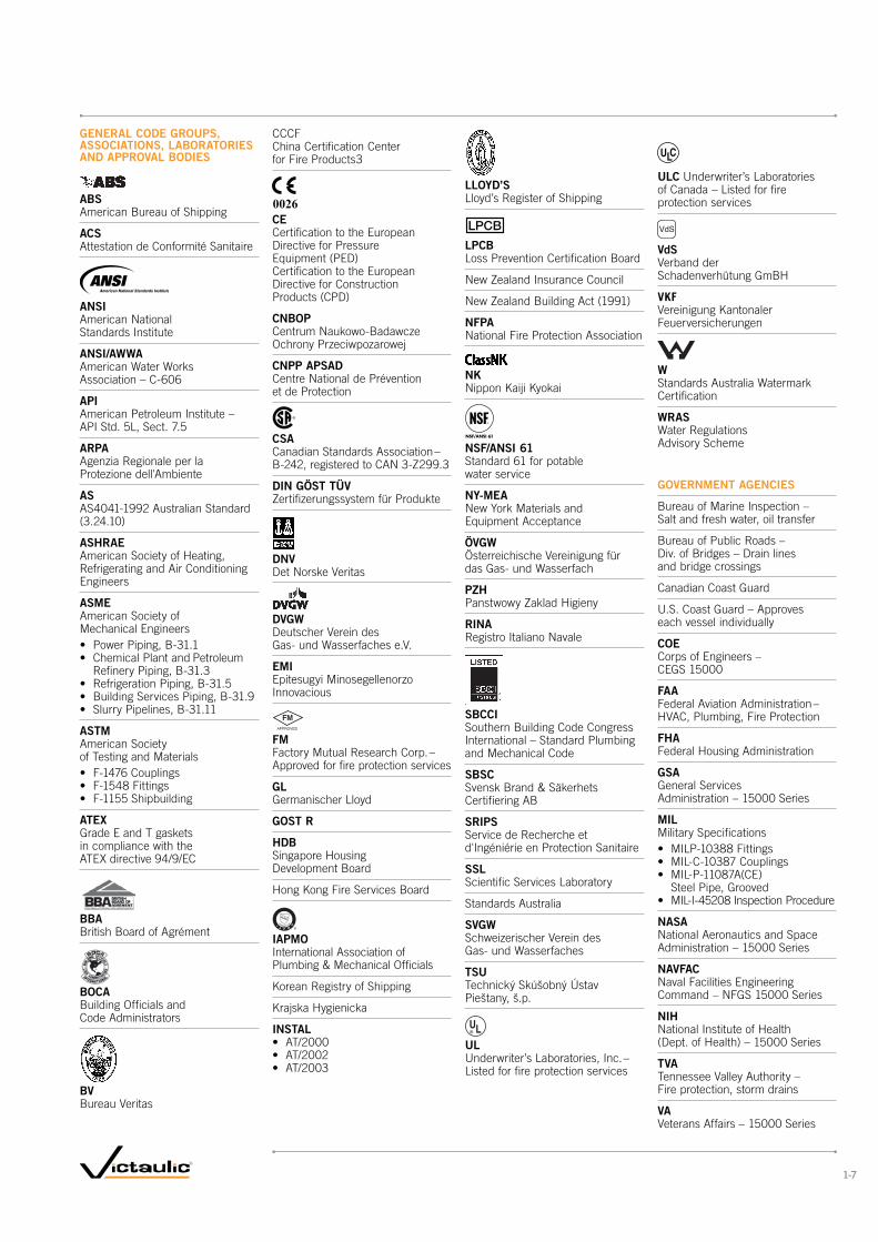
Accepted Worldwide
Victaulic grooved end, plain end and other piping
system components are tested and accepted for
a variety of services throughout the world by the
primary code and approval bodies.
A partial listing of the many agencies, associations,
code group laboratories and organizations which have
accepted, listed and tested Victaulic products are
shown on the facing page. Copies of specific standards
can be obtained by contacting your local Victaulic
representative, or by requesting publication 02.02.
1-6
LLOYD’S Lloyd’s Register of Shipping
LPCB Loss Prevention Certification Board
New Zealand Insurance Council
New Zealand Building Act (1991)
NFPA National Fire Protection Association
NK Nippon Kaiji Kyokai
NSF/ANSI 61 Standard 61 for potable water service
NY-MEA New York Materials and Equipment Acceptance
ÖVGW Österreichische Vereinigung für das Gas- und Wasserfach
PZH Panstwowy Zaklad Higieny
RINA Registro Italiano Navale
SBCCI Southern Building Code Congress International – Standard Plumbing and Mechanical Code
SBSC Svensk Brand & Säkerhets Certifiering AB
SRIPS Service de Recherche et d'Ingéniérie en Protection Sanitaire
SSL Scientific Services Laboratory
Standards Australia
SVGW Schweizerischer Verein des Gas- und Wasserfaches
TSU Technický Skúšobný Ústav Pieštany, š.p.
UL Underwriter’s Laboratories, Inc. – Listed for fire protection services
GENERAL CODE GROUPS, ASSOCIATIONS, LABORATORIES AND APPROVAL BODIES
ABS American Bureau of Shipping
ACS Attestation de Conformité Sanitaire
ANSI American National Standards Institute
ANSI/AWWA American Water Works Association – C-606
API American Petroleum Institute – API Std. 5L, Sect. 7.5
ARPA Agenzia Regionale per la Protezione dell'Ambiente
AS AS4041-1992 Australian Standard (3.24.10)
ASHRAE American Society of Heating, Refrigerating and Air Conditioning Engineers
ASME American Society of Mechanical Engineers
Refinery Piping, B-31.3
ASTM American Society of Testing and Materials
ATEX Grade E and T gaskets in compliance with the ATEX directive 94/9/EC
BBA British Board of Agrément
BOCA Building Officials and Code Administrators
BV Bureau Veritas
CCCF China Certification Center for Fire Products3
0026
CE Certification to the European Directive for Pressure Equipment (PED) Certification to the European Directive for Construction Products (CPD)
CNBOP Centrum Naukowo-Badawcze Ochrony Przeciwpozarowej
CNPP APSAD Centre National de Prévention et de Protection
CSA Canadian Standards Association – B-242, registered to CAN 3-Z299.3
DIN GÖST TÜV Zertifizerungssystem für Produkte
DNV Det Norske Veritas
DVGW Deutscher Verein des Gas- und Wasserfaches e.V.
EMI Epitesugyi Minosegellenorzo Innovacious
FM
APPROVED FM Factory Mutual Research Corp. – Approved for fire protection services
GL Germanischer Lloyd
GOST R
HDB Singapore Housing Development Board
Hong Kong Fire Services Board
IAPMO International Association of Plumbing & Mechanical Officials
Korean Registry of Shipping
Krajska Hygienicka
INSTAL
ULC Underwriter’s Laboratories of Canada – Listed for fire protection services
VdS
VdS Verband der Schadenverhütung GmBH
VKF
Vereinigung Kantonaler Feuerversicherungen
W Standards Australia Watermark Certification
WRAS Water Regulations Advisory Scheme
GOVERNMENT AGENCIES
Bureau of Marine Inspection – Salt and fresh water, oil transfer
Bureau of Public Roads – Div. of Bridges – Drain lines and bridge crossings
Canadian Coast Guard
U.S. Coast Guard – Approves each vessel individually
COE Corps of Engineers – CEGS 15000
FAA Federal Aviation Administration – HVAC, Plumbing, Fire Protection
FHA Federal Housing Administration
GSA General Services Administration – 15000 Series
MIL Military Specifications
Steel Pipe, Grooved
NASA National Aeronautics and Space Administration – 15000 Series
NAVFAC Naval Facilities Engineering Command – NFGS 15000 Series
NIH National Institute of Health (Dept. of Health) – 15000 Series
TVA Tennessee Valley Authority – Fire protection, storm drains
VA Veterans Affairs – 15000 Series
1-7

Introduction This Victaulic General Catalog has been written for the piping system installer, designer,
specification writer and owner as a basic reference guide for data about Victaulic
mechanical piping methods. This catalog is organized to provide information in the
context and form most readily usable. For easy identification of major sections of interest,
see the condensed table of contents on pg. 1-1, for a fully detailed index, see pg. 14-1.
For more detailed information, consult Design Data, Section 26.01.
Important
Information
Victaulic has developed, in over 80 years in mechanical piping, variations of piping
practice for use on a wide variety of piping materials.
Victaulic standard grooved pipe couplings are designed for use with pipe grooved to
meet Victaulic groove specifications and Victaulic grooved end fittings, valves, and
related grooved end components only. They are not intended for use with plain end pipe
and/or fittings. Victaulic plain end couplings are designed for use only with plain end
or beveled end steel pipe (unless otherwise indicated) and Victaulic plain end fittings.
Victaulic plain end couplings must not be used with grooved end or threaded end
pipe and/or fittings. Nor are they intended for use with Advanced Groove System (AGS)
components used on 350 – 600 mm/14 – 24" pipe sizes.
Pipe must be prepared to meet Victaulic specifications outlined for each specific
product style. Performance data listed herein is based on proper pipe preparation.
The proper gasket must be selected for the service intended. It should be noted
that there are various services for which Victaulic gaskets are not recommended.
Reference should always be made to the latest Victaulic Gasket Selection Guide
(request publication 05.01) for specific gasket service recommendations and for
a listing of services which are not recommended. Gaskets for Victaulic products always
must be lubricated for proper assembly. Gasket lubricant must meet manufacturer’s
specifications. Thorough lubrication of the gasket exterior, including the lips and/or pipe
ends and housing interiors, is essential to prevent gasket pinching. Lubrication assists
proper gasket seating and alignment during installation.
Victaulic has a complete line of tools for preparing pipe to Victaulic specifications.
Use of these tools is recommended in preparing pipe to receive Victaulic products.
Always read and understand the Tool Operating Instructions supplied with every Victaulic
tool prior to using any tools. All data contained herein, is subject to change without notice.
WWW.VICTAULIC.COM1-8
Design Data
SEC
TIO
N 1
: D
ESIG
N D
ATA

Notice The technical and performance data, weights, dimensions and specifications published
in this catalog supersede all previously published data.
Victaulic Company maintains a policy of continual product improvement and, therefore,
reserves the right to change product specifications, designs, and standard equipment
without notice and without incurring obligation.
For the most up-to-date Victaulic product information, please visit www.victaulic.com.
The material presented in this catalog is intended for piping design reference in utilization
of Victaulic products for their intended application. It is not intended as a substitute
for competent, professional assistance which is an obvious requisite to any specific
application.
Reference should always be made to the specific Victaulic Field Installation Handbook
for the product you are installing. The following is a list of handbooks that can be
requested for free from Victaulic:
I-100 General Handbook
I-600 Copper Products Handbook
I-900 HDPE Products Handbook
Handbooks are included with each shipment of Victaulic products for complete
installation and assembly data, and are available in PDF format on our website
at www.victaulic.com.
All rights reserved. No part of this Victaulic catalog may be reproduced, stored in a retrieval system, or transmitted, in any form or by any means, electronic, mechanical, photocopy, recording or otherwise, without the prior written permission of Victaulic Company.
© Copyright 2007, Victaulic Company.
® Registered trademark of Victaulic Company.
Design Reference should always be made to design information available at no charge on
request from Victaulic. Good piping practices should always prevail. Specific pressures,
temperatures, external or internal loads, performance standards and tolerances must
never be exceeded. Many applications require recognition of special conditions, code
requirements and use of safety factors. Qualified engineers must make these decisions.
While every effort has been made to ensure its accuracy, Victaulic Company, its subsidiaries
and affiliated companies, make no express or implied warranty of any kind respecting
the information contained in this catalog or the material referred to herein.
Anyone making use of the information or material contained herein does so at their
own risk and assumes any and all liability resulting from such use.
Installation
WWW.VICTAULIC.COM 1-9
Design Data
SEC
TIO
N 1
: DE
SIG
N D
ATA

Nominal Imperial Inches – Size Group
Outside Diameter mm/Spec Ref
DIN mm
ANSI inches
1/2 21.3 mm 15 ½
¾ 26.7 mm 20/26.9 mm ¾
1 33.4 mm 25/33.7 mm 1
1 1/4 42.2 mm 32/42.4 mm 1 1/4
1 1/2 48.3 mm 40 1 1/2
2 60.3 mm DN & ISO 50 2
2 1/2 73.1 mm — 2 ½
76.1 mm DIN/ISO (3 OD) DN & ISO 65 —
3 88.9 mm DN & ISO 80 3
4 108 mm China and old DIN DIN 108 mm —
114.3 mm DN & ISO 100 4
5 133 mm China and old DIN DIN 133 mm —
139.7 mm DIN/ISO (5.5 OD) DN & ISO 125 —
141.3 mm — 5
6 159 mm China and old DIN DIN 159 mm —
165.1 mm JIS (6.5 OD) — —
168.3 mm DN & ISO 150 6
8 216.3 JIS — —
219.1 mm DN 200 8
10 267.4 JIS — —
273 mm DN 250 10
12 318.5 JIS — —
323.9 mm DN 300 12
14 355.6 mm DN 350 14
377 mm China — —
16 406.4 mm DN 400 16
426 mm China — —
18 457.2 mm DN 450 18
480 mm China — —
20 508 mm DN 500 20
530 mm China — —
22 558.8 mm — 22
580 mm China — —
24 610 mm DN 600 24
630 mm China — —
26 660 mm — 26
28 711 mm DN 700 28
30 762 mm — 30
32 813 mm DN 800 32
34 864 mm — 34
36 914 mm DN 900 36
40 1016 mm DN 1000 40
42 1067 mm DN 1050 42
44 1118 mm DN 1100 44
46 1168 mm DN 1150 46
48 1219 mm DN 1200 48
Pipe Size Designations
Victaulic product data is
utilized worldwide and all
technical data is shown in
both imperial (U.S.) and
metric terms. The following
chart shows a comparison
between typical metric
and IPS pipe sizes.
IMPORTANT NOTES:
Nominal designations are used where the actual OD of the pipe matches the ANSI size. Otherwise both the nominal and actual OD are listed.
* Nominal sizes
WWW.VICTAULIC.COM1-10
Design Data
SEC
TIO
N 1
: D
ESIG
N D
ATA
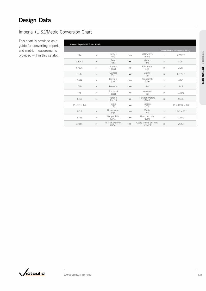
Convert Imperial (U.S.) to Metric
Convert Metric to Imperial (U.S.)
25.4 ×Inches
(In.)Millimeters
(mm)× 0.03937
0.3048 ×Feet (Ft.)
Meters (m)
× 3.281
0.4536 ×Pounds
(Lbs.)Kilograms
(kg)× 2.205
28.35 ×Ounces
(Oz.)Grams
(g)× 0.03527
6.894 ×Pressure
(psi)Kilopascals
(kPa)× 0.145
.069 × Pressure Bar × 14.5
4.45 ×End Load
(Lbs.)Newtons
(N)× 0.2248
1.356 ×Torque (Lb. Ft.)
Newton Meters × 0.738
(F – 32) ÷ 1.8Temp.
(°F)Celsius
(°C)(C + 17.78) × 1.8
745.7 ×Horsepower
(hp)Watts
(w)× 1.341 × 10⁻³
3.785 ×Gal. per Min.
(GPM)Liters per min.
(L/M)× 0.2642
3.7865 ×10⁻³ Gal. per Min.
(GPM)Cubic Meters per min.
(m3/m)× 264.2
This chart is provided as a
guide for converting imperial
and metric measurements
provided within this catalog.
Imperial (U.S.)/Metric Conversion Chart
WWW.VICTAULIC.COM 1-11
Design Data
SEC
TIO
N 1
: DE
SIG
N D
ATA

Zero-Flex®
Rigid CouplingSTYLE 07, PG. 1-16 AGS STYLE W07, PG. 5-3
Pipe CouplingSTYLE 770, PG. 1-20
CouplingSTYLE 77, PG. 1-17 AGS STYLE W77, PG. 5-3
CouplingSTYLE 75, PG. 1-19
®
STYLE 741, PG. 1-21
STYLE 743, PG. 1-23
CouplingSTYLE 750, PG. 1-24
STYLE 741, PG. 1-22 AGS STYLE W741, PG. 5-4
WWW.VICTAULIC.COM1-12
Couplings
SEC
TIO
N 1
: C
OU
PLIN
GS

Style 07
Style 77
Style 75
Style 770
Style 750
Style 78
Style 72 †
Style 791
Style HP-70
Style HP-70ES
STANDARD
REDUCING
FLUSHSEAL
ENDSEAL
† Separate gasket specifically designed for outlet couplings.
CouplingSTYLE 72, PG. 1-26
®
CouplingSTYLE 791 AND STYLE 792 ASSEMBLY TOOL, PG. 1-27
Rigid
CouplingSTYLE HP-70, PG. 1-28
®
STYLE HP-70ES, PG. 1-29
PG. 1-30
PRODUCTS
1-12 Couplings
®
CouplingSTYLE 78, PG. 1-25
WWW.VICTAULIC.COM 1-13
Couplings
SEC
TIO
N 1
: CO
UPLIN
GS

SizeAllow. Pipe End Sep.
Nominal Size mm
Inches
Actual Outside Diameter
mm Inches
mm Inches
20 26.9 1.23/4 1.050 0.05
25 33.7 1.21 1.315 0.05
32 42.4 1.21 1/4 1.660 0.05
40 48.3 1.21 1/2 1.900 0.05
50 60.3 1.72 2.375 0.07
65 73.0 1.72 1/2 2.875 0.07
76.1 mm 76.1 1.73.000 0.07
80 88.9 1.73 3.500 0.07
108.0 mm 108.0 4.14.250 0.16
100 114.3 4.14 4.500 0.16
133.0 mm 133.0 4.15.250 0.16
139.7 mm 139.7 4.15.500 0.16
§ Except for HP-70 and HP-70ES coupling which have the following allowable pipe end separation:
HP-70: 50 – 100 mm/2 – 4" sizes: 3.6 mm/0.14" 150– 300 mm/6 – 12" sizes: 6.4 mm/0.25"
HP-70ES: 50 – 100 mm/2 – 4" sizes: 4.8 mm/0.19" 150 – 200 mm/6 – 8" sizes: 6.7 mm/0.27" 250 – 300 mm/10 – 12" sizes: 7.1 mm/0.28"
* These figures do NOT apply to 350 – 600 mm/14 – 24" Style W07 AGS rigid couplings. Allowable pipe end separation is 6.4 mm/0.25" for all sizes of Style W07.
SizeAllow. Pipe End Sep.
Nominal Size mm
Inches
Actual Outside Diameter
mm Inches
mm Inches
125 141.3 4.15 5.563 0.16
159.0 mm 159.0 4.16.250 0.16
165.1 mm 165.1 4.16.500 0.16
150 168.3 4.16 6.625 0.16
200 219.1 4.88 8.625 0.19
250 273.0 3.310 10.750 0.13
300 323.9 3.312 12.750 0.13
350 355.6 3.314* 14.000 0.13
400 406.4 3.316* 16.000 0.13
450 457.0 3.318* 18.000 0.13
500 559.0 3.320* 20.000 0.13
600 610.0 3.324* 24.000 0.13
IMPORTANT NOTES:
ONLY FLEXIBLE couplings are recommended for the installation of expansion loops as stated in Calculating and Accommodating Pipe Line Thermal Growth Section 26.02. All eight couplings assembling the four elbows of the loop must be flexible. The use of rigid couplings to install the straight run adjacent to the expansion loop is a recommended practice.
This also applies to couplings installed on the perpendicular leg(s) at the end(s) of a straight pipe run or on pipe line offsets. If system movement is to be accommodated, flexible couplings must be utilized.
Rigid couplings must NOT be utilized to accommodate any system movement.
Should you have any questions regarding the proper use of our products, contact Engineering Services at [email protected].
Sizes shown are nominal DN sizes, except where actual mm sizes are shown.
WARNING
Depressurize and drain the piping system before attempting
to install, remove, or adjust any Victaulic piping products.
Failure to do so could result in personal injury, property
damage, joint leakage and/or joint failure.
WWW.VICTAULIC.COM1-14
Couplings
SEC
TIO
N 1
: C
OU
PLIN
GS

SizeAllow. Pipe End Sep. † Deflect. Fr. C L †
Nominal Size mm
Inches
Actual Outside Diameter
mm Inches
mm Inches
Degrees per Coupling
Pipe mm/m In./Ft.
20 26.9 0 – 1.6 3° 24' 603/4 1.050 0 – 0.06 0.72
25 33.7 0 – 1.6 2° 43' 481 1.315 0 – 0.06 0.57
32 42.4 0 – 1.6 2° 10' 381 1/4 1.660 0 – 0.06 0.45
40 48.3 0 – 1.6 1° 56' 331 1/2 1.900 0 – 0.06 0.40
50 60.3 0 – 1.6 1° 31' 272 2.375 0 – 0.06 0.32
65 73.0 0 – 1.6 1° 15' 222 1/2 2.875 0 – 0.06 0.26
76.1 mm 76.1 0 – 1.6 1° 12' 223.000 0 – 0.06 0.26
80 88.9 0 – 1.6 1° 2' 183 3.500 0 – 0.06 0.22
90 101.6 0 – 1.6 0° 54' 163 1/2 4.000 0 – 0.06 0.19
108.0 mm 108.0 0 – 3.2 1° 41' 294.250 0 – 0.13 0.35
100 114.3 0 – 3.2 1° 36' 284 4.500 0 – 0.13 0.34
120 127.0 0 – 3.2 1° 26' 214 1/2 5.000 0 – 0.13 0.25
133.0 mm 133.0 0 – 3.2 1° 21' 235.250 0 – 0.13 0.28
139.7 mm 139.7 0 – 3.2 1° 18' 235.500 0 – 0.13 0.28
125 141.3 0 – 3.21° 18'
225 5.563 0 – 0.13 0.27
152.4 mm 152.4 0 – 3.2 1° 12' 176.000 0 – 0.13 0.21
§ Except for Style 72 outlet couplings. Contact Victaulic for details.
† These values are based on standard roll grooved pipe. Figures for standard cut grooved pipe may be doubled. See notes below.
@ Allowable pipe end separation for Style W77 AGS flexible couplings in this size range are 3.1 – 9.5 mm/0.125 – 0.375".
IMPORTANT NOTES:
Sizes shown are nominal DN sizes, except where actual mm sizes are shown.
SizeAllow. Pipe End Sep. † Deflect. Fr. C L †
Nominal Size mm
Inches
Actual Outside Diameter
mm Inches
mm Inches
Degrees per Coupling
Pipe mm/m In./Ft.
159.0 mm 159.0 0 – 3.2 1° 9' 206.250 0 – 0.13 0.24
165.1 mm 165.1 0 – 3.2 1° 6' 196.500 0 – 0.13 0.23
150 168.3 0 – 3.2 1° 5' 196 6.625 0 – 0.13 0.23
203.2 mm 203.2 0 – 3.2 0° 54' 138.000 0 – 0.13 0.16
200 219.1 0 – 3.2 0° 50' 158 8.625 0 – 0.13 0.18
254.0 mm 254.0 0 – 3.2 0° 43' 1310.000 0 – 0.13 0.15
250 273.0 0 – 3.2 0° 40' 1210 10.750 0 – 0.13 0.14
304.8 mm 304.8 0 – 3.2 0° 36' 1112.000 0 – 0.13 0.13
300 323.9 0 – 3.2 0° 34' 1012 12.750 0 – 0.13 0.12
350 355.6 0 – 3.2 0° 31' 914 @ 14.000 0 – 0.13 0.11
375 381.0 0 – 3.2 0° 29' 815 15.000 0 – 0.13 0.10
400 406.4 0 – 3.2 0° 27' 816 @ 16.000 0 – 0.13 0.10
450 457.0 0 – 3.2 0° 24' 718 @ 18.000 0 – 0.13 0.08
500 508.0 0 – 3.2 0° 22' 720 @ 20.000 0 – 0.13 0.08
550 559.0 0 – 3.2 0° 19' 622 22.000 0 – 0.13 0.07
600 610.0 0 – 3.2 0° 18' 624 @ 24.000 0 – 0.13 0.07
-
GENERAL NOTES:
Working Pressure and End Load are total, from all internal and external loads, based on standard weight (ANSI) steel pipe, standard roll or cut grooved in accordance with Victaulic specifications. Contact Victaulic for performance on other pipe.
Warning: For one time field test only, the Maximum Joint Working Pressure may be increased to 1½ times the figures shown (except Style HP-70ES).
Allowable Pipe End Separation and Deflection figures show the maximum nominal range of movement available at each joint for standard roll grooved pipe. Figures for standard cut grooved pipe may be doubled. These figures are maximums; for design and installation purposes these figures should be reduced by: 50% for 20 – 90 mm/¾ – 3½"; 25% for 100 mm/4" and larger.
WWW.VICTAULIC.COM 1-15
Couplings
SEC
TIO
N 1
: CO
UPLIN
GS

SizeMax. Work Pressure *
Max. End Load *
Allow. Pipe End Sep. * Dimensions
Approx. Wgt. Each
Nominal Size mm
Inches
Actual Outside Dia.
mm Inches
kPa psi
N Lbs.
mm Inches
X mm
Inches
Y mm
Inches
Z mm
Incheskg
Lbs.
25 33.7 5175 2890 1.2 60 107 47 0.71 1.315 750 650 0.05 2.36 4.22 1.84 1.6
32 42.4 5175 7210 1.2 68 117 47 0.71 1/4 1.660 750 1,620 0.05 2.69 4.62 1.84 1.6
40 48.3 5175 9480 1.2 75 148 47 0.71 1/2 1.900 750 2,130 0.05 2.94 5.81 1.84 1.6
50 60.3 5175 14775 1.7 85 147 47 1.02 2.375 750 3,320 0.07 3.35 5.78 1.84 2.3
65 73.0 5175 21695 1.7 98 162 47 1.22 1/2 2.875 750 4,875 0.07 3.88 6.38 1.84 2.6
76.1 mm 76.1 5175 23585 1.7 107 168 47 1.63.000 750 5,300 0.07 4.21 6.61 1.84 3.6
80 88.9 5175 32105 1.7 115 173 47 1.43 3.500 750 7,215 0.07 4.54 6.81 1.84 3.0
108.0 mm 108.0 5175 47325 4.1 141 203 53 2.44.250 750 10,635 0.16 5.56 7.98 2.07 5.2
100 114.3 5175 53065 4.1 148 209 53 2.44 4.500 750 11,925 0.16 5.81 8.21 2.07 5.3
133.0 mm 133.0 4825 67395 4.1 170 244 53 3.45.250 700 15,145 0.16 6.69 9.60 2.07 7.4
139.7 mm 139.7 4825 73980 4.1 176 249 53 3.45.500 700 16,625 0.16 6.94 9.82 2.07 7.6
125 141.3 5175 81100 4.1 179 251 53 3.45 5.563 750 18,225 0.16 7.03 9.89 2.07 7.4
159.0 mm 159.0 4825 95520 4.1 199 268 53 4.26.250 700 21,465 0.16 7.84 10.54 2.07 9.2
165.1 mm 165.1 4825 103305 4.1 207 275 53 3.86.500 700 23,225 0.16 8.13 10.84 2.07 8.3
150 168.3 4825 107380 4.1 210 275 53 3.86 6.625 700 24,130 0.16 8.26 10.83 2.07 8.3
200 219.1 4130 155750 4.8 268 349 64 6.88 § 8.625 600 35,000 0.19 10.54 13.74 2.51 15.1
250 273.0 3450 202030 3.3 327 431 65 10.710 § 10.750 500 45,400 0.13 12.86 16.98 2.56 23.5
300 323.9 2750 226950 3.3 377 480 65 12.812 § 12.750 400 51,000 0.13 14.86 18.88 2.56 28.2
350 – 600 14 – 24
See Style W07, pg. 5-3, Request Publication 20.02
§ Couplings 200 mm/8", 250 mm/10", 300 mm/12"sizes are available to JIS standards. Refer to Publication 06.17 for details.
* Refer to General Notes on pg. 1-15.
IMPORTANT NOTES:
Sizes shown are nominal DN sizes, except where actual mm sizes are shown.
Y
X
Z
Zero-Flex
Rigid Coupling
STYLE 07
06.02
TYPICAL FOR ALL SIZES
WWW.VICTAULIC.COM1-16
Couplings
SEC
TIO
N 1
: C
OU
PLIN
GS
SizeMax. Work Pressure *
Max. End Load *
Allow. Pipe End Sep. * Dimensions
Approx. Wgt. Each
Nominal Size mm
Inches
Actual Outside Dia.
mm Inches
kPa psi
N Lbs.
mm Inches
X mm
Inches
Y mm
Inches
Z mm
Incheskg
Lbs.
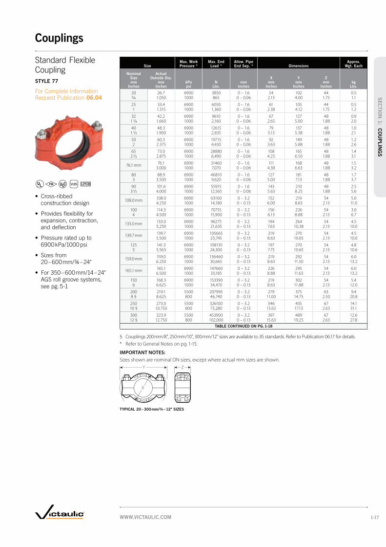
20 26.7 6900 3850 0 – 1.6 54 102 44 0.53/4 1.050 1000 865 0 – 0.06 2.13 4.00 1.75 1.1
25 33.4 6900 6050 0 – 1.6 61 105 44 0.51 1.315 1000 1,360 0 – 0.06 2.38 4.12 1.75 1.2
32 42.2 6900 9610 0 – 1.6 67 127 48 0.91 1/4 1.660 1000 2,160 0 – 0.06 2.65 5.00 1.88 2.0
40 48.3 6900 12615 0 – 1.6 79 137 48 1.01 1/2 1.900 1000 2,835 0 – 0.06 3.13 5.38 1.88 2.1
50 60.3 6900 19715 0 – 1.6 92 149 48 1.22 2.375 1000 4,430 0 – 0.06 3.63 5.88 1.88 2.6
65 73.0 6900 28880 0 – 1.6 108 165 48 1.42 1/2 2.875 1000 6,490 0 – 0.06 4.25 6.50 1.88 3.1
76.1 mm 76.1 6900 31460 0 – 1.6 111 168 48 1.53.000 1000 7,070 0 – 0.06 4.38 6.63 1.88 3.2
80 88.9 6900 46810 0 – 1.6 127 181 48 1.73 3.500 1000 9,620 0 – 0.06 5.00 7.13 1.88 3.7
90 101.6 6900 55915 0 – 1.6 143 210 48 2.53 1/2 4.000 1000 12,565 0 – 0.06 5.63 8.25 1.88 5.6
108.0 mm 108.0 6900 63100 0 – 3.2 152 219 54 5.04.250 1000 14,180 0 – 0.13 6.00 8.63 2.13 11.0
100 114.3 6900 70755 0 – 3.2 156 226 54 3.04 4.500 1000 15,900 0 – 0.13 6.13 8.88 2.13 6.7
133.0 mm 133.0 6900 96275 0 – 3.2 194 264 54 4.55.250 1000 21,635 0 – 0.13 7.63 10.38 2.13 10.0
139.7 mm 139.7 6900 105665 0 – 3.2 219 270 54 4.55.500 1000 23,745 0 – 0.13 8.63 10.65 2.13 10.0
125 141.3 6900 108135 0 – 3.2 197 270 54 4.85 5.563 1000 24,300 0 – 0.13 7.75 10.65 2.13 10.6
159.0 mm 159.0 6900 136460 0 – 3.2 219 292 54 6.06.250 1000 30,665 0 – 0.13 8.63 11.50 2.13 13.2
165.1 mm 165.1 6900 147660 0 – 3.2 226 295 54 6.06.500 1000 33,185 0 – 0.13 8.88 11.63 2.13 13.2
150 168.3 6900 153390 0 – 3.2 219 302 54 5.46 6.625 1000 34,470 0 – 0.13 8.63 11.88 2.13 12.0
200 219.1 5500 207995 0 – 3.2 279 375 63 9.48 § 8.625 800 46,740 0 – 0.13 11.00 14.75 2.50 20.8
250 273.0 5500 326100 0 – 3.2 346 435 67 14.110 § 10.750 800 73,280 0 – 0.13 13.63 17.13 2.63 31.1
300 323.9 5500 453900 0 – 3.2 397 489 67 12.612 § 12.750 800 102,000 0 – 0.13 15.63 19.25 2.63 27.8
TABLE CONTINUED ON PG. 1-18
§ Couplings 200 mm/8", 250 mm/10", 300 mm/12" sizes are available to JIS standards. Refer to Publication 06.17 for details.
* Refer to General Notes on pg. 1-15.
IMPORTANT NOTES:
Sizes shown are nominal DN sizes, except where actual mm sizes are shown.
Y
X
Z
Coupling
STYLE 77
06.04
TYPICAL 20 – 300 mm/¾ – 12" SIZES
WWW.VICTAULIC.COM 1-17
Couplings
SEC
TIO
N 1
: CO
UPLIN
GS
SizeMax. Work Pressure *
Max. End Load *
Allow. Pipe End Sep. * Dimensions
Approx. Wgt. Each
Nominal Size mm
Inches
Actual Outside Dia.
mm Inches
kPa psi
N Lbs.
mm Inches
X mm
Inches
Y mm
Inches
Z mm
Incheskg
Lbs.
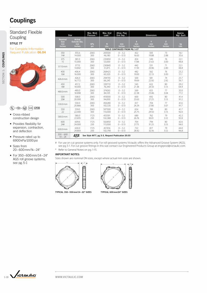
TABLE CONTINUED FROM PG. 1-17
350 355.6 2065 205500 0 – 3.2 422 505 73 16.114# 14.000 300 46,180 0 – 0.13 16.63 19.88 2.88 35.6
375 381.0 2065 235850 0 – 3.2 454 549 76 22.115 15.000 300 53,000 0 – 0.13 17.88 21.63 3.00 48.8
377.0 mm 377.0 2065 230845 0 – 3.2 442 531 71 22.114.842 300 51,875 0 – 0.13 17.39 20.96 2.80 48.8
400 406.4 2065 268425 0 – 3.2 482 562 76 23.216# 16.000 300 60,320 0 – 0.13 19.00 22.13 3.00 51.1
426.0 mm 426.0 2065 294795 0 – 3.2 500 581 74 25.716.772 300 66,245 0 – 0.13 19.69 22.92 2.92 56.7
450 457.2 2065 339710 0 – 3.2 543 622 80 29.218# 18.000 300 76,340 0 – 0.13 21.38 24.50 3.13 64.4
480.0 mm 480.0 2065 374265 0 – 3.2 569 655 77 35.018.898 300 84,105 0 – 0.13 22.38 25.86 3.04 77.2
500 508.0 2065 418300 0 – 3.2 600 692 80 41.420# 20.000 300 94,000 0 – 0.13 23.63 27.25 3.13 91.2
530.0 mm 530.0 2065 456280 0 – 3.2 617 704 77 41.620.866 300 102,535 0 – 0.13 24.29 27.80 3.07 91.7
550 559.0 2065 507300 0 – 3.2 654 749 80 41.722 22.000 300 114,000 0 – 0.13 25.75 29.50 3.13 92.0
580.0 mm 580.0 1725 455591 0 – 3.2 680 762 79 42.222.835 250 102,380 0 – 0.13 26.76 30.01 3.12 92.8
600 609.6 1725 502850 0 – 3.2 704 794 80 42.624# 24.000 250 113,000 0 – 0.13 27.75 31.25 3.13 94.0
630.0 mm 630.0 1725 457416 0 – 3.2 722 817 79 44.024.803 250 102,790 0 – 0.13 28.42 32.16 3.12 96.8
350 – 600 14 – 24
See Style W77, pg. 5-3, Request Publication 20.03
# For use on cut groove systems only. For roll grooved systems Victaulic offers the Advanced Groove System (AGS), see pg. 5-1. For cut groove fittings in this size contact our Engineered Products Group at [email protected].
* Refer to General Notes on pg. 1-15.
IMPORTANT NOTES:
Sizes shown are nominal DN sizes, except where actual mm sizes are shown.
X
Y Z Y Z
X
Coupling
STYLE 77
06.04
TYPICAL 350 – 550 mm/14 – 22" SIZES TYPICAL 600 mm/24" SIZES
WWW.VICTAULIC.COM1-18
Couplings
SEC
TIO
N 1
: C
OU
PLIN
GS

SizeMax. Work Pressure *
Max. End Load *
Allow. Pipe End Sep. * Dimensions
Approx. Wgt. Each
Nominal Size mm
Inches
Actual Outside Dia.
mm Inches
kPa psi
N Lbs.
mm Inches
X mm
Inches
Y mm
Inches
Z mm
Incheskg
Lbs.
25 33.4 3450 3025 0 – 1.6 61 108 45 0.61 1.315 500 680 0 – 0.06 2.38 4.27 1.77 1.3
32 42.2 3450 4805 0 – 1.6 68 117 45 0.61 1/4 1.660 500 1,080 0 – 0.06 2.68 4.61 1.77 1.4
40 48.3 3450 6320 0 – 1.6 74 122 45 0.61 1/2 1.900 500 1,420 0 – 0.06 2.91 4.82 1.77 1.5
50 60.3 3450 9860 0 – 1.6 87 133 48 0.82 2.375 500 2,215 0 – 0.06 3.43 5.22 1.88 1.7
65 73.0 3450 14440 0 – 1.6 98 144 48 0.92 1/2 2.875 500 3,245 0 – 0.06 3.88 5.68 1.88 1.9
76.1 mm 76.1 3450 15730 0 – 1.6 102 150 48 0.93.000 500 3,535 0 – 0.06 4.00 5.90 1.88 1.9
80 88.9 3450 21360 0 – 1.6 114 178 48 1.33 3.500 500 4,800 0 – 0.06 4.50 7.00 1.88 2.9
90 101.6 3450 28035 0 – 1.6 127 191 48 1.33 1/2 4.000 500 6,300 0 – 0.06 5.00 7.50 1.88 2.9
108.0 mm 108.0 3100 28395 0 – 3.2 141 198 54 1.74.250 450 6,380 0 – 0.13 5.55 7.79 2.13 3.7
100 114.3 3450 35380 0 – 3.2 147 204 54 1.94 4.500 500 7,950 0 – 0.13 5.80 8.03 2.13 4.1
120 127.0 3100 39250 0 – 3.2 156 240 54 2.54 1/2 5.000 450 8,820 0 – 0.13 6.13 9.43 2.13 5.5
133.0 mm 133.0 3100 43325 0 – 3.2 166 238 54 2.75.250 450 9,735 0 – 0.13 6.55 9.37 2.13 6.0
139.7 mm 139.7 3100 47460 0 – 3.2 173 244 54 2.95.500 450 10,665 0 – 0.13 6.80 9.59 2.13 6.3
125 141.3 3100 48660 0 – 3.2 175 256 54 2.65 5.563 450 10,935 0 – 0.13 6.88 10.07 2.13 5.8
152.4 mm 152.4 3100 56670 0 – 3.2 187 266 48 2.86.000 450 12,735 0 – 0.13 7.38 10.48 1.88 6.2
159.0 mm 159.0 3100 61405 0 – 3.2 194 266 54 3.16.250 450 13,800 0 – 0.13 7.63 10.49 2.13 6.8
165.1 mm 165.1 3100 66483 0 – 3.2 199 271 52 3.36.500 450 14,940 0 – 0.13 7.84 10.66 2.06 7.2
150 168.3 3100 69085 0 – 3.2 203 281 58 3.26 6.625 450 15,525 0 – 0.13 8.00 11.07 2.13 7.0
203.2 mm# 203.2 3100 100725 0 – 3.2 247 339 54 5.78.000 450 22,635 0 – 0.13 9.72 13.33 2.31 12.6
200 219.1 3100 116945 0 – 3.2 263 355 59 5.68 8.625 450 26,280 0 – 0.13 10.34 13.97 2.32 12.4
254.0 mm# 254.0 2400 122375 0 – 3.2 309 402 64 9.410.000 350 27,500 0 – 0.13 12.16 15.81 2.53 20.8
304.8 mm# 304.8 2400 175775 0 – 3.2 360 449 64 10.712.000 350 39,500 0 – 0.13 14.16 17.69 2.53 23.6
# Style 74 Couplings.
* Refer to General Notes on pg. 1-15.
IMPORTANT NOTES:
Sizes shown are nominal DN sizes, except where actual mm sizes are shown.
ZY
X
STYLE 75
06.05
TYPICAL FOR ALL SIZES
WWW.VICTAULIC.COM 1-19
Couplings
SEC
TIO
N 1
: CO
UPLIN
GS

SizeMax. Work Pressure *
Max. End Load * Coupling Dimensions
Nominal Range of Linear Movement ‡
Approx. Wgt. Each
Nominal Size mm
Inches
Actual Outside Dia.
mm Inches
kPa psi
N Lbs.
X mm
Inches
Y mm
Inches
Z mm
Inches
Minimum mm
Inches
Maximum mm
Incheskg
Lbs.
650 660.4 2580 885990 756 870 127 0 9.7 68.026 26.000 375 199,099 29.75 34.25 5.00 0 0.38 150.0
700 711.0 2270 904236 807 923 127 0 9.7 78.028 28.000 330 203,199 31.75 36.33 5.00 0 0.38 175.0
750 762.0 2065 943658 857 973 127 0 9.7 90.730 30.000 300 212,058 33.75 38.32 5.00 0 0.38 200.0
800 813.0 1790 930517 908 1027 127 0 9.7 102.132 32.000 260 209,105 35.75 40.43 5.00 0 0.38 225.0
900 914.0 1380 905909 1010 1126 127 0 9.7 113.436 36.000 200 203,575 39.75 44.33 5.00 0 0.38 250.0
1050 1067.0 1000 893961 1162 1310 146 7.9 17.5 181.442 42.000 145 200,890 45.75 51.56 5.76 0.31 0.69 400.0
‡ Nominal linear movement and deflection are dependent upon pipe properly roll or cut grooved to Victaulic specifications. Maximum allowable linear movement is the difference between minimum and maximum pipe end separation subject to tolerances (Request Publication 26.01).
* Refer to General Notes on pg. 1-15.
IMPORTANT NOTES:
Sizes shown are nominal DN sizes, except where actual mm sizes are shown.
Y
X
Z
X
Y Z
Pipe Coupling
STYLE 770
06.03
TYPICAL 650 – 900 mm/ 26 – 36" SIZES
TYPICAL 1050 mm/42" SIZES
WWW.VICTAULIC.COM1-20
Couplings
SEC
TIO
N 1
: C
OU
PLIN
GS

Size PN10 Flanges PN16 FlangesSealing Surface Dimensions
Approx. Wgt. Each
Nominal Size mm
Inches
Actual Outside Dia.
mm Inches
Max. Work Pressure *
Bars * psi
Max. End Load *
N Lbs.
Max. Work Pressure *
Bars * psi
Max. End Load *
N Lbs.
A Max. mm
Inches
B Min. mm
Inches
W mm
Inches
Z mm
Incheskg
Lbs.
50 60.3 10 2850 16 4561 60 87 177 20 1.42 2.375 145 640 230 1025 2.38 3.41 6.97 0.79 3.1
76.1 mm76.1 10 4540 16 7275 76 103 208 20 2.1
3.000 145 1020 230 1635 3.00 4.05 8.19 0.79 4.7
80 88.9 10 6210 16 9925 89 115 218 22 2.43 3.500 145 1395 230 2230 3.50 4.53 8.58 0.87 5.4
100 114.3 10 10260 16 16420 114 141 251 24 3.54 4.500 145 2305 230 3690 4.50 5.55 9.88 0.94 7.7
133.0 mm133.0 10 13893 16 22229 133 160 274 25 4.55.250 145 3123 230 4997 5.24 6.30 10.78 1.00 10.0
139.7 mm139.7 10 15174 16 24279 140 168 274 25 4.25.500 145 3411 230 5478 5.51 6.61 10.78 1.00 9.2
159.0 mm159.0 10 19800 16 31400 159 187 307 26 4.56.250 145 4450 230 7056 6.25 7.36 12.09 1.02 10.0
165.1 mm165.1 10 21400 16 34236 165 195 303 25 4.56.500 145 4811 230 7632 6.50 7.68 11.93 1.00 10.0
150 168.3 10 22250 16 35600 168 198 302 25 4.56 6.625 145 5000 230 8000 6.63 7.78 11.89 1.00 10.0
200 219.1 10 37690 16 60320 219 252 368 # 29 # 7.58 8.625 145 8470 230 13555 8.63 9.94 14.49 1.14 16.6
250 273.0 10 58560 16 93695 273 313 437 § 27 § 11.010 10.750 145 13160 230 21055 10.75 12.31 17.20 1.06 24.2
300 323.9 10 82370 16 131810 324 365 478 ‡ 32 ‡ 17.412 12.750 145 18510 230 29620 12.75 14.31 18.82 1.26 38.4
* Refer to Publication 06.06 for more details.
# PN16 dimensions (mm/inches): W = 360/14.17; Z = 30/1.18.
§ PN16 dimensions (mm/inches): W = 438/17.24; Z = 30/1.18.
‡ PN16 dimensions (mm/inches): W = 478/18.82; Z = 32/1.26.
IMPORTANT NOTES:
Style 741 Vic-Flange adapters provide rigid joints when used on pipe with standard cut or roll groove dimensions and consequently allow no linear or angular movement at the joint. When used with Victaulic Series 700 butterfly valves, plastic pipe or light wall metallic pipe, small teeth in I.D. of key section should be removed and may only be used on one side of the valve. Contact Victaulic for information on AS2129 - Table E; ISO 2084 (PN10); DIN 2532 (PN10) and JIS B-2210 (10k) flanges.
For restrictions on where and how Vic-Flange adapters and flange washers can be used, refer to Publication 06.06.
Sizes shown are nominal DN sizes, except where actual mm sizes are shown.
Z
WA
B
STYLE 741
06.06
TYPICAL 50 – 300 mm/2 – 12" SIZES
Orange area of mating face must be free from gouges, undulations
or deformities of any type for effective sealing.
WWW.VICTAULIC.COM 1-21
Couplings
SEC
TIO
N 1
: CO
UPLIN
GS

SizeMax. Work Pressure *
Max. End Load *
Sealing Surface Dimensions
Approx. Wgt. Each
Nominal Size mm
Inches
Actual Outside Dia.
mm Inches
kPa psi
N Lbs.
A Max. mm
Inches
B Min. mm
Inches
W mm
Inches
Z mm
Incheskg
Lbs.
50 60.3 2065 5920 60 87 172 19 1.42 2.375 300 1,330 2.38 3.41 6.75 0.75 3.1
65 73.0 2065 8680 73 99 200 22 2.12 1/2 2.875 300 1,950 2.88 3.91 7.87 0.88 4.8
80 88.9 2065 12840 89 115 211 24 2.43 3.500 300 2,885 3.50 4.53 8.29 0.94 5.3
100 114.3 2065 21225 114 141 251 24 3.44 4.500 300 4,770 4.50 5.53 9.87 0.94 7.4
125 141.3 2065 32440 141 171 277 25 3.95 5.563 300 7,290 5.56 6.71 10.90 1.00 8.6
165.1 mm165.1 2065 44320 165 195 303 25 4.56.500 300 9,960 6.50 7.66 11.92 1.00 10.0
150 168.3 2065 46060 168 198 302 25 4.56 6.625 300 10,350 6.63 7.78 11.90 1.00 9.9
200 219.1 2065 77875 219 252 368 29 7.58 8.625 300 17,500 8.63 9.94 14.50 1.13 16.6
250 273.0 2065 121110 273 313 438 30 11.010 10.750 300 27,215 10.75 12.31 17.24 1.19 24.2
300 323.9 2065 170270 324 364 514 32 21.212 12.750 300 38,285 12.75 14.31 20.25 1.25 46.8
350 355.6 2065 205500 356 416 622 37 28.114# 14.000 300 46,180 14.00 16.39 24.50 1.44 62.0
400 406.4 2065 268335 406 467 689 37 35.816# 16.000 300 60,300 16.00 18.39 27.12 1.44 79.0
450 457.0 2065 339700 457 508 737 40 37.318# 18.000 300 76,340 18.00 20.00 29.00 1.56 82.3
500 508.0 2065 419400 508 572 800 43 46.920# 20.000 300 94,250 20.00 22.50 31.50 1.69 103.3
600 610.0 2065 603865 610 705 914 49 64.424# 24.000 300 135,700 24.00 27.75 36.00 1.94 142.0
350 – 600 14 – 24
See Style W741, pg. 5-4, Request Publication 20.04
* Refer to Publication 06.06 for more details.
# For cut groove systems only. For 350 – 600 mm/14 – 24" roll groove systems, AGS (Advanced Groove System) products are used. Style 741 is not compatible with the AGS system.
IMPORTANT NOTES:
Style 741 Vic-Flange adapters provide rigid joints when used on pipe with standard cut or roll groove dimensions and consequently allow no linear or angular movement at the joint. When used with Victaulic Series 700 butterfly valves, plastic pipe or lightwall metallic pipe, small teeth in I.D. of key section should be removed and may be used on one side of the valve. Contact Victaulic for information on AS2129 - Table E; ISO 2084 (PN10); DIN 2532 (PN10) and JIS B-2210 (10K) flanges. Total bolts required to be supplied by installer, may be ordered from Victaulic.
For restrictions on where and how Vic-Flange adapters and flange washers can be used, refer to Publication 06.06.
Sizes shown are nominal DN sizes, except where actual mm sizes are shown.
Z
WA
B W
Z
A
B
STYLE 741
06.06
TYPICAL 50 – 300 mm/2 – 12" SIZES
Orange area of mating face must be free from gouges, undulations
or deformities of any type for effective sealing.
TYPICAL 350 – 600 mm/14 – 24" SIZES
Orange area of mating face must be free from gouges, undulations
or deformities of any type for effective sealing.
WWW.VICTAULIC.COM1-22
Couplings
SEC
TIO
N 1
: C
OU
PLIN
GS

SizeMax. Work Pressure *
Max. End Load *
Sealing Surface Dimensions
Approx. Wgt. Each
Nominal Size mm
Inches
Actual Outside Dia.
mm Inches
kPa psi
N Lbs.
A Max. mm
Inches
B Min. mm
Inches
W mm
Inches
Z mm
Incheskg
Lbs.
50 60.3 4960 14200 60 87 196 24 2.22 2.375 720 3,190 2.38 3.41 7.70 0.93 4.8
65 73.0 4960 20780 73 99 219 27 3.42 1/2 2.875 720 4,670 2.88 3.91 8.61 1.06 7.4
80 88.9 4960 30815 89 115 241 30 4.13 3.500 720 6,925 3.50 4.53 9.48 1.18 9.1
100 114.3 4960 50930 114 141 288 33 6.94 4.500 720 11,445 4.50 5.53 11.35 1.31 15.3
125 141.3 4960 77875 141 171 313 36 8.05 5.563 720 17,500 5.56 6.72 12.31 1.43 17.7
150 168.3 4960 110380 168 198 350 38 10.66 6.625 720 24,805 6.63 7.78 13.77 1.50 23.4
200 219.1 4960 187100 219 252 424 43 15.68 8.625 720 42,045 8.63 9.94 16.68 1.68 34.3
250 273.0 4960 290650 273 313 489 49 21.910 10.750 720 65,315 10.75 12.31 19.25 1.93 48.3
300 323.9 4960 408870 324 364 565 52 32.012 12.750 720 91,880 12.75 14.31 22.25 2.06 70.5
* Refer to Publication 06.06 for more details.
IMPORTANT NOTES:
Style 743 Vic-Flange adapters must be ordered as a factory assembly when connected to a Victaulic fitting or valve. Contact Victaulic for details. Total bolts required to be supplied by installer, may be ordered from Victaulic.
For restrictions on where and how Vic-Flange adapters and flange washers can be used, refer to Publication 06.06.
Sizes shown are nominal DN sizes, except where actual mm sizes are shown.
Z
AB W
Remove to mate to "at-faced
"anges.
STYLE 743
06.06
TYPICAL FOR ALL SIZES
Orange area of mating face must be free from gouges, undulations
or deformities of any type for effective sealing.
WWW.VICTAULIC.COM 1-23
Couplings
SEC
TIO
N 1
: CO
UPLIN
GS

SizeMax. Work Pressure *
Max. End Load *
Allow. Pipe End Sep. * Dimensions
Approx. Wgt. Each
Nominal Size mm
IncheskPa psi
N Lbs.
mm Inches
X mm
Inches
Y mm
Inches
Z mm
Incheskg
Lbs.
50 × 25 2400 4450 0 – 1.8 85 134 48 1.22 1 350 1,000 0 – 0.07 3.38 5.28 1.88 22.7
40 2400 4450 0 – 1.8 85 134 48 1.01 1/2 350 1,000 0 – 0.07 3.38 5.28 1.88 2.0
65 × 50 3450 9850 0 – 1.8 102 151 48 1.42 1/2 2 500 2,215 0 – 0.07 4.00 5.93 1.88 3.1
76.1 × 50 2400 6900 0 – 1.8 111 168 48 2.12 350 1,550 0 – 0.07 4.38 6.63 1.88 4.6
80 × 50 2400 6900 0 – 1.8 121 181 48 2.23 2 350 1,550 0 – 0.07 4.75 7.13 1.88 4.9
65 3450 14460 0 – 1.8 121 181 48 2.02 1/2 500 3,250 0 – 0.07 4.75 7.13 1.88 4.3
88.9 × 76.1 2400 10125 0 – 1.8 121 181 48 1.9350 2,275 0 – 0.07 4.75 7.13 1.88 4.2
100 × 50 2400 6900 0 – 3.2 159 226 57 3.74 2 350 1,550 0 – 0.13 6.25 8.90 2.25 8.1
65 2400 10125 0 – 3.2 159 226 57 3.92 1/2 350 2,275 0 – 0.13 6.25 8.90 2.25 8.6
80 3450 21400 0 – 3.2 152 226 57 3.03 500 4,810 0 – 0.13 6.00 8.90 2.25 6.7
114.3 × 76.1 2400 10125 0 – 3.2 159 226 57 3.1350 2,275 0 – 0.13 6.25 8.90 2.25 6.9
125 × 100 2400 24765 0 – 3.2 182 272 54 5.15 4 350 5,565 0 – 0.13 7.18 10.70 2.13 11.2
150 × 100 2400 24765 0 – 3.2 219 302 57 7.66 4 350 5,565 0 – 0.13 8.63 11.90 2.25 16.7
125 2400 37825 0 – 3.2 211 302 57 5.95 350 8,500 0 – 0.13 8.31 11.90 2.25 12.9
165.1 ×100 2400 24765 0 – 3.2 219 302 57 6.9
4 350 5,565 0 – 0.13 8.63 11.90 2.25 15.2
200 × 150 2400 53400 0 – 3.2 275 378 64 10.28 6 350 12,000 0 – 0.13 10.81 14.88 2.50 22.4
* Refer to General Notes on pg. 1-15.
IMPORTANT NOTES:
Style 750 reducing couplings should not be used with end caps (No. 60) in systems where a vacuum may be developed. Contact Victaulic for details.
Sizes shown are nominal DN sizes, except where actual mm sizes are shown.
X
ZY
STYLE 750
06.08
TYPICAL FOR ALL SIZES
WWW.VICTAULIC.COM1-24
Couplings
SEC
TIO
N 1
: C
OU
PLIN
GS

SizeMax. Work Pressure *
Max. End Load *
Allow. Pipe End Sep. * Dimensions
Approx. Wgt. Each
Nominal Size mm
Inches
Actual Outside Dia.
mm Inches
kPa psi
N Lbs.
mm Inches
X mm
Inches
Y mm
Inches
Z mm
Incheskg
Lbs.
25 33.4 2065 1825 0 – 1.6 70 83 44 0.41 1.315 300 410 0 – 0.06 2.75 3.25 1.75 0.8
32 42.2 2065 2890 0 – 1.6 79 95 48 0.51 1/4 1.660 300 650 0 – 0.06 3.13 3.75 1.88 1.1
40 48.3 2065 3780 0 – 1.6 89 114 48 0.81 1/2 1.900 300 850 0 – 0.06 3.50 4.50 1.88 1.7
50 60.3 2065 5920 0 – 1.6 102 121 48 0.82 2.375 300 1,330 0 – 0.06 4.00 4.75 1.88 1.7
65 73.0 2065 8680 0 – 1.6 121 149 48 1.12 1/2 2.875 300 1,950 0 – 0.06 4.75 5.88 1.88 2.5
80 88.9 2065 12840 0 – 1.6 137 159 48 1.33 3.500 300 2,885 0 – 0.06 5.38 6.25 1.88 2.8
100 114.3 2065 21225 0 – 3.2 175 197 54 2.54 4.500 300 4,770 0 – 0.13 6.88 7.75 2.13 5.5
125 141.3 2065 32440 0 – 3.2 222 241 54 4.45 5.563 300 7,290 0 – 0.13 8.75 9.50 2.13 9.8
150 168.3 2065 46060 0 – 3.2 251 270 54 4.96 6.625 300 10,350 0 – 0.13 9.88 10.63 2.13 10.7
200 219.1 2065 77875 0 – 3.2 311 330 60 6.98 8.625 300 17,500 0 – 0.13 12.25 13.00 2.38 15.3
* Refer to General Notes on pg. 1-15.
IMPORTANT NOTES:
Refer to Victaulic Pocket Handbook I-100 for special safety precautions when used for concrete pumping.
Sizes shown are nominal DN sizes, except where actual mm sizes are shown.
Z Y
X
STYLE 78
06.09
TYPICAL FOR ALL SIZES
WWW.VICTAULIC.COM 1-25
Couplings
SEC
TIO
N 1
: CO
UPLIN
GS

SizeMax. Work Pressure *
Allow. Pipe End Sep. * Dimensions
Approx. Wgt. Each
Run × Reducing Outlet
Nominal Size mm/Inches
kPa psi
mm Inches
T † mm
Inches
V § mm
Inches
X mm
Inches
Y mm
Inches
Z mm
Incheskg
Lbs.
40 × 15 3450 19 – 22 52 67 75 114 70 0.61 1/2 1/2 500 0.75 – 0.88 2.06 2.63 2.94 4.50 2.75 1.4
20 3450 19 – 22 52 67 75 114 70 0.63/4 500 0.75 – 0.88 2.06 2.63 2.94 4.50 2.75 1.4
25 3450 19 – 22 49 67 75 114 70 0.61 500 0.75 – 0.88 1.94 2.63 2.94 4.50 2.75 1.4
50 × 15 3450 20 – 22 63 77 86 127 70 1.6 2 1/2 500 0.81 – 0.88 2.47 3.03 3.38 5.00 2.75 3.5
20 3450 20 – 22 63 77 86 127 70 1.13/4 500 0.81 – 0.88 2.47 3.03 3.38 5.00 2.75 2.5
25 3450 20 – 22 60 77 86 127 70 1.11 500 0.81 – 0.88 2.34 3.03 3.38 5.00 2.75 2.5
65 × 15 3450 20 – 22 65 79 98 152 70 2.02 1/2 1/2 500 0.81 – 0.88 2.56 3.13 3.88 6.00 2.75 4.5
20 3450 20 – 22 65 79 98 152 70 2.13/4 500 0.81 – 0.88 2.56 3.13 3.88 6.00 2.75 4.6
25 3450 20 – 22 62 79 98 152 70 2.11 500 0.81 – 0.88 2.44 3.13 3.88 6.00 2.75 4.6
32 3450 32 – 38 76 94 103 175 83 2.31 1/4 500 1.25 – 1.50 3.00 3.69 4.06 6.88 3.25 5.0
40 3450 32 – 38 — 94 103 175 83 2.31 1/2 500 1.25 – 1.50 3.69 4.06 6.88 3.25 5.0
80 × 20 3450 13 – 16 70 84 114 178 60 1.53 3/4 500 0.50 – 0.63 2.75 3.31 4.50 7.00 2.38 3.4
25 3450 32 – 38 103 121 121 203 83 3.21 500 1.25 – 1.50 4.06 4.75 4.75 8.00 3.25 7.0
32 3450 32 – 38 103 121 121 203 83 3.21 1/4 500 1.25 – 1.50 4.06 4.75 4.75 8.00 3.25 7.0
40 3450 32 – 38 — 108 121 203 83 3.21 1/2 500 1.25 – 1.50 4.25 4.75 8.00 3.25 7.0
100 20 3450 11 – 16 83 97 145 213 64 3.14 × 3/4 500 0.44 – 0.63 3.25 3.81 5.69 8.38 2.50 6.8
25 3450 11 – 16 — 97 145 213 64 3.11 500 0.44 – 0.63 3.81 5.69 8.38 2.50 6.8
40 2750 41 – 46 99 117 156 229 94 5.21 1/2 400 1.63 – 1.81 3.91 4.59 6.13 9.00 3.69 11.4
50 2750 41 – 46 — 117 156 229 94 5.22 400 1.63 – 1.81 4.59 6.13 9.00 3.69 11.4
150 25 2750 41 – 46 157 175 206 305 94 8.26 × 1 400 1.63 – 1.81 6.19 6.88 8.13 12.00 3.69 18.0
40 2750 41 – 46 157 175 206 305 94 8.21 1/2 400 1.63 – 1.81 6.19 6.88 8.13 12.00 3.69 18.0
50 2750 41 – 46 — 154 206 305 94 8.22 400 1.63 – 1.81 6.06 8.13 12.00 3.69 18.0
* Refer to General Notes on pg. 1-15.
§ Center of run to end of fittings.
† Center of run to the engaged pipe end. Female threaded outlet only (dimensions approximate).
IMPORTANT NOTES:
No. 60 Cap is not for use in vacuum services with Style 72 or 750 couplings.
Sizes shown are nominal DN sizes, except where actual mm sizes are shown.
VT
Y Z
X
STYLE 72
06.10
TYPICAL FOR ALL SIZES
WWW.VICTAULIC.COM1-26
Couplings
SEC
TIO
N 1
: C
OU
PLIN
GS

SizeMax. Work Pressure *
Max. End Load *
Allow. Pipe End Sep. *
Locking Pin Size Dimensions
Approx. Wgt. Each
Nominal Size mm
Inches
Actual Outside Dia.
mm Inches
kPa psi
N Lbs.
mm Inches
Dia. × Length mm
Inches
X mm
Inches
Y mm
Inches
Z mm
Inches kg
Lbs.
50 60.3 4825 13795 0 – 1.6 8 × 48 90 120 47 0.82 2.375 700 3,100 0 – 0.06 5/16 × 1 7/8 3.56 4.71 1.84 1.8
65 73.0 4825 20205 0 – 1.6 10 × 48 104 139 47 1.22 1/2 2.875 700 4,540 0 – 0.06 3/8 × 1 7/8 4.09 5.48 1.84 2.7
80 88.9 4825 29950 0 – 1.6 10 × 48 120 156 47 1.23 3.500 700 6,730 0 – 0.06 3/8 × 1 7/8 4.72 6.15 1.84 2.6
100 114.3 4825 49530 0 – 3.2 11 × 51 154 194 49 2.24 4.500 700 11,130 0 – 0.13 7/16 × 2 6.06 7.62 1.93 4.8
150 168.3 4135 92005 0 – 3.2 13 × 52 209 259 51 2.96 6.625 600 20,675 0 – 0.13 1/2 × 2 1/16 8.24 10.18 2.06 6.3
200 219.1 3450 129940 0 – 3.2 13 × 59 267 318 59 5.48 8.625 500 29,200 0 – 0.13 1/2 × 2 5/16 10.52 12.50 2.31 12.0
* Refer to General Notes on pg. 1-15.
IMPORTANT NOTES:
Complete coupling includes one-piece hinged housing, gasket and locking pin only. Assembly tool Style 792 is required for assembly (one tool fits all size couplings).
Please see Publication 06.11 for tool clearance dimensions.
Sizes shown are nominal DN sizes, except where actual mm sizes are shown.
X
Z
NOTE Assembly Tool Clearance
Y
STYLE 791 AND STYLE 792
ASSEMBLY TOOL
06.11
TYPICAL FOR ALL SIZES
WWW.VICTAULIC.COM 1-27
Couplings
SEC
TIO
N 1
: CO
UPLIN
GS

SizeMax. Work Pressure *
Max. End Load *
Fixed Pipe End Sep. * Dimensions
Approx. Wgt. Each
Nominal Size mm
Inches
Actual Outside Dia.
mm Inches
kPa psi
N Lbs.
mm Inches
X mm
Inches
Y mm
Inches
Z mm
Inches kg
Lbs.
50 60.3 6900 19715 3.6 89 168 51 1.52 2.375 1000 4,430 0.14 3.50 6.68 2.00 3.2
65 73.0 6900 28881 3.6 105 181 51 1.82 1/2 2.875 1000 6,490 0.14 4.13 7.13 2.00 4.0
80 88.9 6900 42810 3.6 121 197 51 2.03 3.500 1000 9,620 0.14 4.75 7.75 2.00 4.4
100 114.3 6900 70755 6.4 152 245 54 3.44 4.500 1000 15,900 0.25 6.00 9.63 2.13 7.5
150 168.3 6900 153390 6.4 219 321 64 7.36 6.625 1000 34,470 0.25 8.63 12.68 2.50 16.0
200 219.1 5500 207995 6.4 279 381 70 11.88 8.625 800 46,740 0.25 11.00 15.00 2.75 26.1
250 273.0 5500 323250 6.4 343 438 76 14.910 10.750 800 72,640 0.25 13.50 17.25 3.00 32.8
300 323.9 5500 453900 6.4 397 486 80 20.912 12.750 800 102,000 0.25 15.63 19.13 3.13 46.0
350 355.6 4100 410800 6.4 425 559 99 29.014 # 14.000 600 92,360 0.25 16.75 22.00 3.88 64.0
400 406.4 4100 536400 6.4 476 613 99 32.716 # 16.000 600 120,600 0.25 18.75 24.13 3.88 72.0
# These sizes are not intended for use on AGS roll groove pipe.
* Refer to General Notes on pg. 1-15.
IMPORTANT NOTES:
Sizes shown are nominal DN sizes, except where actual mm sizes are shown.
Y Z
X
X
Y Z
Rigid Coupling
STYLE HP-70
06.12
TYPICAL 50 – 300 mm/2 – 12" SIZES TYPICAL 350 – 400 mm/14 – 16" SIZES
WWW.VICTAULIC.COM1-28
Couplings
SEC
TIO
N 1
: C
OU
PLIN
GS

SizeMax. Work Pressure †
Max. End Load *
Fixed Pipe End Sep. * Dimensions
Approx. Wgt. Each
Nominal Size mm
Inches
Actual Outside Dia.
mm Inches
kPa psi
N Lbs.
mm Inches
X mm
Inches
Y mm
Inches
Z mm
Inches kg
Lbs.
50 60.3 17250 48950 4.8 87 765 48 1.52 2.375 2500 11,000 0.19 3.44 6.51 1.88 3.2
65 73.0 17250 72090 4.8 102 180 48 1.82 1/2 2.875 2500 16,200 0.19 4.00 7.10 1.88 4.0
80 88.9 17250 113030 4.8 119 197 48 2.13 3.500 2500 25,400 0.19 4.69 7.74 1.88 4.6
100 114.3 17250 173550 4.8 151 242 54 3.74 4.500 2500 39,000 0.19 5.94 9.54 2.13 8.2
150 168.3 13800 306160 6.7 216 320 60 7.46 6.625 2000 68,800 0.27 8.50 12.61 2.38 16.4
200 219.1 10350 389375 6.7 278 380 70 11.88 8.625 1500 87,500 0.27 10.94 14.97 2.75 26.0
250 273.0 8600 509525 7.1 682 437 73 16.910 10.750 1250 114,500 0.28 13.43 17.22 2.88 37.2
300 323.9 8600 715560 7.1 395 484 76 19.112 12.750 1250 160,800 0.28 15.56 19.06 3.00 42.0
† Warning: For one time field test only, the Maximum Joint Working Pressure may be increased to 1¼ the figure shown.
* Refer to General Notes on pg. 1-15.
IMPORTANT NOTES:
HP-70ES couplings must always be used with pipe or fittings grooved to Victaulic “ES” dimensions. HP-70ES couplings cannot be used with Victaulic Series 700 butterfly valves.
Sizes shown are nominal DN sizes, except where actual mm sizes are shown.
Y Z
X
EndSeal fittings for plastic
coated pipe, pg. 1-30
STYLE HP-70ES
06.13
TYPICAL FOR ALL SIZES
WWW.VICTAULIC.COM 1-29
Couplings
SEC
TIO
N 1
: CO
UPLIN
GS

SizeNo. 62-ES 90º Elbow
No. 63-ES* 45º Elbow
No. 64-ES* Tee
No. 35-ES* Cross
No. 22-ES Header Tee
Nominal Size mm
Inches
Actual Outside Diameter
mm Inches
C to E mm
Inches
Approx. Weight Each
kg Lbs.
C to E mm
Inches
Approx. Weight Each
kg Lbs.
C to E mm
Inches
Approx. Weight Each
kg Lbs.
C to E mm
Inches
Approx. Weight Each
kg Lbs.
C to E mm
Inches
Approx. Weight Each
kg Lbs.
50 60.3 83 1.1 51 0.8 83 1.9 83 1.8 — —2 2.375 3.25 2.5 2.00 1.8 3.25 4.2 3.25 3.9
65 73.0 95 2.3 57 1.3 95 3.6 95 3.0 — —2 1/2 2.875 3.75 5.0 2.25 2.9 3.75 7.9 3.75 6.6
50 – 90 60.3 – 88.9 — — — — — — — — 108 1.52 – 3 2.375 – 3.500 4.25 3.4
50 – 100 60.3 – 114.3 — — — — — — — — 127 1.92 – 4 2.375 – 4.500 5.00 4.1
80 88.9 108 2.7 64 1.9 108 7.3 108 6.4 — —3 3.500 4.25 6.0 2.50 4.3 4.25 16.0 4.25 14.2
100 114.3 127 4.7 76 3.9 127 10.7 127 7.2 — —4 4.500 5.00 10.3 3.00 8.5 5.00 23.5 5.00 15.8
150 168.3 165 12.3 89 7.5 165 12.2 165 20.9 — —6 † 6.625 6.50 27.2 3.50 16.5 6.50 27.0 6.50 46.0
* Steel Fabricated - Cast Full Flow.
† For sizes to 300 mm/12" consult Victaulic.
IMPORTANT NOTES:
Steel Full Flow elbows available with longer center to end dimensions. Contact Victaulic for details.
Sizes shown are nominal DN sizes, except where actual mm sizes are shown.
C to E
C to E C to E
CtoE
C to E
CtoE
CtoE
C to EC to E
Cto E
NO. 62-ES
NO. 63-ES
NO. 64-ES
NO. 35-ES
NO. 22-ES
07.03
NO. 62-ES NO. 63-ES NO. 64-ES NO. 35-ES NO. 22-ES
WWW.VICTAULIC.COM1-30
Couplings
SEC
TIO
N 1
: C
OU
PLIN
GS

WWW.VICTAULIC.COM 1-31
SEC
TIO
N 1
: CO
UPLIN
GS
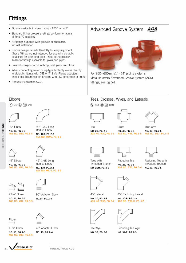
Elbows
NO. 10, PG. 2-3 AGS NO. W10, PG. 5-5
NO. 11, PG. 2-3 AGS NO. W11, PG. 5-5
NO. 12, PG. 2-3 AGS NO. W12, PG. 5-5
NO. 100, PG. 2-3 AGS NO. W100, PG. 5-5
NO. 110, PG. 2-3 AGS NO. W110, PG. 5-5
NO.18, PG. 2-4
NO. 19, PG. 2-4
NO. 20, PG. 2-5 AGS NO. W20, PG. 5-5
NO. 35, PG. 2-5 AGS NO. W35, PG. 5-5
NO. 33, PG. 2-5 AGS NO. W33, PG. 5-5
NO. 29M, PG. 2-5
NO. 25, PG. 2-6 AGS NO. W25, PG. 5-6 NO. 29, PG. 2-6
NO. 30, PG. 2-8 AGS NO. W30, PG. 5-7
NO. 30-R, PG. 2-8 AGS NO. W30-R, PG. 5-7
NO. 32, PG. 2-9 NO. 32-R, PG. 2-9NO. 13, PG. 2-3 AGS NO. W13, PG. 5-5
WWW.VICTAULIC.COM2-1
Fittings
SEC
TIO
N 2
: F
ITTIN
GS

PRODUCTS
2-1 Fittings
FOR ABRASION RESISTANCE ONLY FOR CORROSION AND/OR ABRASION RESISTANCE
NO. 42, PG. 2-10 AGS NO. W42, PG. 5-8
NO. 60, PG. 2-10 AGS NO. W60, PG. 5-8
NO. 41, PG. 2-11 NO. 45F, PG. 2-11 NO. 46F, PG. 2-11 NO. 41-DN, PG. 2-12
NO. 45R, PG. 2-11 NO. 46R, PG. 2-11 AGS NO. W45R, PG. 5-8
NO. 80, PG. 2-13
NO. 48, PG. 2-13
NO. 50, PG. 2-14 AGS NO. W50, PG. 5-9
NO. 52, PG. 2-16 NO. 52F, PG. 2-16
NO. 43, PG. 2-10 AGS NO. W43, PG. 5-8 AGS NO. W49, PG. 5-8
NO. 40, PG. 2-10
NO. 51, PG. 2-14 AGS NO. W51, PG. 5-9
WWW.VICTAULIC.COM 2-2
Fittings
SEC
TIO
N 2
: FIT
TIN
GS

SizeNo. 10
90º ElbowNo. 11
45º ElbowNo. 12
22½° ElbowNo. 13
11¼° ElbowNo. 100 (1½ D)
90° Long Radius ElbowNo. 110 (1½ D)
45° Long Radius Elbow
Nominal Size mm
Inches
Actual Outside Dia.
mm Inches
C to E mm
Inches
Approx. Wgt. Each
kg Lbs.
C to E mm
Inches
Approx. Wgt. Each
kg Lbs.
C to E mm
Inches
Approx. Wgt. Each
kg Lbs.
C to E mm
Inches
Approx. Wgt. Each
kg Lbs.
C to E mm
Inches
Approx. Wgt. Each
kg Lbs.
C to E mm
Inches
Approx. Wgt. Each
kg Lbs.
20 26.9 57 0.2 38 0.2 41 — 35 — — — — —3/4 1.050 2.25 0.5 1.50 0.5 1.63 (sw) 1.38 (sw)
25 33.7 57 0.3 44 0.3 83 0.3 35 0.1 — — — —1 1.315 2.25 0.6 1.75 0.6 3.25 @ 0.6 1.38 (sw) 0.3
32 42.4 70 0.5 44 0.4 44 0.4 35 0.2 — — — —1 1/4 1.660 2.75 1.0 1.75 0.9 1.75 0.8 1.38 (sw) 0.5
40 48.3 70 0.5 44 0.4 44 0.4 35 0.2 — — — —1 1/2 1.900 2.75 1.2 1.75 0.9 1.75 0.8 1.38 (sw) 0.5
50 60.3 83 0.8 51 0.6 95 0.6 35 0.5 111 1.1 70 0.82 2.375 3.25 1.8 2.00 1.3 3.75 @ 1.4 1.38 1.0 4.38 2.5 2.75 1.8
65 73.0 95 1.5 57 1.0 102 1.0 38 0.5 127 1.9 76 1.32 1/2 2.875 3.75 3.2 2.25 2.2 4.00 @ 2.3 1.50 1.1 5.00 4.1 3.00 2.8
76.1 mm 76.1 95 1.7 57 1.5 — — — — — — — —3.000 3.75 3.7 2.25 3.4
80 88.9 108 2.0 64 1.4 114 1.4 38 1.0 149 2.7 86 2.23 3.500 4.25 4.5 2.50 3.1 4.50 @ 3.1 1.50 2.1 5.88 6.0 3.38 4.9
90 101.6 114 2.5 70 2.0 64 1.8 44 1.2 — — — —3 1/2 4.000 4.50 5.6 2.75 4.3 2.50 (sw) 4.0 1.75 (sw) 2.7
108.0 mm 108.0 127 5.0 76 2.5 — — — — — — — —4.250 5.00 11.0 3.00 5.6
100 114.3 127 3.2 76 2.5 73 2.5 44 1.6 191 5.6 102 3.34 4.500 5.00 7.1 3.00 5.6 2.88 5.6 1.75 3.6 7.50 12.3 4.00 7.3
120 127.0 133 4.5 79 2.7 89 3.0 48 1.9 — — — —4 1/2 5.000 5.25 (sw) 10.0 3.13 (sw) 6.0 3.50 6.6 1.88 (sw) 4.2
133.0 mm 133.0 140 5.3 83 3.8 — — — — — — — —5.250 5.50 11.7 3.25 8.3
139.7 mm 139.7 140 5.3 83 3.8 — — — — — — — —5.500 5.50 11.7 3.25 8.3
125 141.3 140 5.3 83 3.8 73 3.5 51 2.2 + 8.3 + 6.75 5.563 5.50 11.7 3.25 8.3 2.88 (sw) 7.8 2.00 (sw) 5.0 18.2 14.8
159.0 mm 159.0 165 8.4 89 4.9 — — — — — — — —6.250 6.50 18.6 3.50 10.8
165.1 mm 165.1 165 7.0 89 4.4 79 5.2 51 3.4 273 13.2 140 8.66.500 6.50 15.5 3.50 9.8 3.13 11.4 2.00 7.4 10.75 29.0 5.50 19.0
150 168.3 165 7.8 89 4.9 159 5.5 51 3.2 273 13.8 140 7.96 6.625 6.50 17.2 3.50 10.8 6.25 @ 12.2 2.00 7.0 10.75 30.4 5.50 17.4
200 219.1 197 13.6 108 9.3 197 9.1 51 4.6 362 30.0 184 16.38 8.625 7.75 29.9 4.25 20.4 7.75 @ 20.0 2.00 10.1 14.25 66.0 7.25 36.0
250 273.0 229 28.7 121 17.0 111 13.6 54 5.3 381 48.5 159 25.910 10.750 9.00 63.3 4.75 37.5 4.38 (sw) 30.0 2.13 (sw) 11.8 15.00 107.0 6.25 57.0
300 323.9 254 33.6 133 30.3 124 18.1 57 13.3 457 70.8 191 40.812 12.750 10.00 74.0 5.25 66.7 4.88 (sw) 40.0 2.25 (sw) 29.3 18.00 156.0 7.50 90.0
350 – 600 14 – 24
See AGS Roll Groove Fittings, pg. 5-2; for 350 – 600 mm/14 – 24" Cut Groove Systems Request Publication 07.01
@ Gooseneck design, end-to-end dimension.
+ Contact Victaulic for details.
# Ductile iron except those marked (sw) which are segmentally welded steel.
IMPORTANT NOTES:
Sizes shown are nominal DN sizes, except where actual mm sizes are shown.
C to E
C to E
C to E
Cto E
C to E
E to E
C to E
C to E
Elbows
NO. 10
NO. 11
NO. 12
NO. 13
NO. 100
NO. 110
07.01 NO. 10 NO. 11 NO. 12 NO. 13 NO. 100 NO. 110
WWW.VICTAULIC.COM2-3
Fittings
SEC
TIO
N 2
: F
ITTIN
GS

SizeNo. 18
90° Adapter Elbow No. 19
45° Adapter Elbow
Nominal Size mm
Inches
Actual Outside Diameter
mm Inches
C to GE mm
Inches
C to TE mm
Inches
Approx. Weight Each
kg Lbs.
C to GE mm
Inches
C to TE mm
Inches
Approx. Weight Each
kg Lbs.
20 26.9 57 57 0.2 38 38 0.23/4 1.050 2.25 2.25 0.5 1.50 1.50 0.5
25 33.7 57 57 0.2 44 44 0.31 1.315 2.25 2.25 0.5 1.75 1.75 0.6
32 42.4 70 70 0.4 44 44 0.31 1/4 1.660 2.75 2.75 0.9 1.75 1.75 0.6
40 48.3 70 70 0.5 44 44 0.41 1/2 1.900 2.75 2.75 1.1 1.75 1.75 0.9
50 60.3 83 108 1.1 51 76 0.92 2.375 3.25 4.25 2.5 2.00 3.00 1.9
65 73.0 95 95 1.4 57 57 1.02 1/2 2.875 3.75 3.75 3.0 2.25 2.25 2.3
80 88.9 108 152 2.6 64 108 2.33 3.500 4.25 6.00 5.8 2.50 4.25 5.0
90 101.6 114 159 3.6 133 133 4.03 1/2 4.000 4.50 6.25 8.0 5.25 5.25 8.8
100 114.3 127 184 5.4 76 133 4.04 4.500 5.00 7.25 12.0 3.00 5.25 8.8
150 168.3 165 165 8.0 89 89 5.86 6.625 6.50 6.50 17.6 3.50 3.50 12.7
@ Available with British Standard Pipe Threads, specify “BSP” clearly on order.
IMPORTANT NOTES:
Sizes shown are nominal DN sizes, except where actual mm sizes are shown.
C toGE
C toTE C to
TE
C toGE
NO. 18
NO. 19
07.01
NO. 19 @NO. 18 @
WWW.VICTAULIC.COM 2-4
Fittings
SEC
TIO
N 2
: FIT
TIN
GS

SizeNo. 20
TeeNo. 35
Cross (sw)No. 33
True Wye (sw)No. 29M
Tee with Threaded Branch
Nominal Size mm
Inches
Actual Outside Dia.
mm Inches
C to E mm
Inches
Approx. Weight Each
kg Lbs.
C to E mm
Inches
Approx. Weight Each
kg Lbs.
C to LE mm
Inches
C to SE mm
Inches
Approx. Weight Each
kg Lbs.
C to GE mm
Inches
C to TE mm
Inches
Approx. Weight Each
kg Lbs.
20 26.9 57 0.3 57 0.4 — — — 57 57 0.33/4 1.050 2.25 0.6 2.25 0.9 2.25 2.25 0.6
25 33.7 57 0.5 57 0.6 57 57 0.5 57 57 0.51 1.315 2.25 1.0 2.25 1.3 2.25 2.25 1.1 2.25 2.25 1.0
32 42.4 70 0.7 70 1.0 70 64 0.7 70 70 0.71 1/4 1.660 2.75 1.5 2.75 2.1 2.75 2.50 1.5 2.75 2.75 1.5
40 48.3 70 0.9 70 1.1 70 70 0.8 70 70 0.91 1/2 1.900 2.75 2.0 2.75 2.5 2.75 2.75 1.8 2.75 2.75 2.0
50 60.3 83 1.4 83 1.7 83 70 1.1 83 108 1.42 2.375 3.25 3.0 3.25 3.8 3.25 2.75 2.5 3.25 4.25 3.00
65 73.0 95 2.0 95 2.8 95 76 2.0 95 95 2.02 1/2 2.875 3.75 4.3 3.75 6.1 3.75 3.00 4.3 3.75 3.75 4.3
76.1 mm 76.1 95 2.4 — — — — — 95 95 2.43.000 3.75 5.2 3.75 3.75 5.2 (sw)
80 88.9 108 3.0 108 4.8 108 83 2.8 108 152 3.13 3.500 4.25 6.8 4.25 10.5 4.25 3.25 6.1 4.25 6.00 6.8
90 101.6 114 3.6 114 5.2 114 89 4.4 114 114 3.63 1/2 4.000 4.50 (sw) 7.9 4.50 11.5 4.50 3.50 9.6 4.50 4.50 7.9 (sw)
108.0 mm 108.0 127 7.0 — — — — — 127 127 7.04.250 5.00 15.5 5.00 5.00 15.5
100 114.3 127 5.4 127 7.2 127 95 4.5 127 184 5.44 4.500 5.00 11.9 5.00 15.8 5.00 3.75 10.0 5.00 7.25 11.9
120 127.0 133 6.8 133 8.4 — — — 133 133 6.84 1/2 5.000 5.25 (sw) 15.0 5.25 18.5 5.25 5.25 15.0 (sw)
133.0 mm 133.0 140 8.1 — — — — — 140 140 8.15.250 5.50 17.8 5.50 5.50 17.8
139.7 mm 139.7 140 8.1 — — — — — 140 140 8.15.500 5.50 17.8 5.50 5.50 17.8
125 141.3 140 8.1 140 9.1 140 102 6.8 140 140 8.15 5.563 5.50 17.8 5.50 20.0 5.50 4.00 15.0 5.50 5.50 17.8 (sw)
159.0 mm 159.0 165 12.3 — — — — — 165 165 12.36.250 6.50 27.1 6.50 6.50 27.1
165.1 mm 165.1 165 10.0 165 12.7 — — — 165 165 10.06.500 6.50 22.0 6.50 28.0 6.50 6.50 22.0
150 168.3 165 1.7 165 12.7 165 114 10.1 165 165 11.76 6.625 6.50 25.7 6.50 28.0 6.50 4.50 22.3 6.50 6.50 25.7 (sw)
200 219.1 197 21.6 197 21.8 197 152 16.3 197 197 21.68 8.625 7.75 47.6 7.75 48.0 7.75 6.00 36.0 7.75 7.75 47.6 (sw)
250 273.0 229 44.9 229 55.1 229 155 31.7 229 229 33.110 10.750 9.00 99.0 9.00 121.5 9.00 6.50 69.9 9.00 9.00 73.0
300 323.9 254 60.3 254 49.9 254 178 36.3 254 254 44.912 12.750 10.00 133.0 10.00 110.0 10.00 7.00 80.0 10.00 10.00 99.0
350 – 600 14 – 24
See AGS Roll Groove Fittings, pg. 5-2; for 350 – 600 mm/14 – 24" Cut Groove Systems Request Publication 07.01
# Ductile iron except those marked (sw) which are segmentally welded steel.
@ Available with British Standard Pipe Threads, specify “BSP” clearly on order.
IMPORTANT NOTES:
Fittings size 650 – 1050 mm/26 – 48" are available roll grooved for installation with Style 770 large diameter pipe couplings, contact Victaulic for details.
Sizes shown are nominal DN sizes, except where actual mm sizes are shown.
C to E
CtoE
NO. 20
C to E
NO. 35
C to LE
C toSE
NO. 33
C toGE
C to TE
NO. 29M @
NO. 20
NO. 35
NO. 33
NO. 29M
07.01
WWW.VICTAULIC.COM2-5
Fittings
SEC
TIO
N 2
: F
ITTIN
GS

SizeNo. 25
Std.No. 29
w/ Thd. BranchApprox.
Weight Each
Nominal Size mm
Inches
C to E mm
Inches
C to E mm
Incheskg
Lbs.
25 × 25 × 20 + + 0.51 1 3/4 1.0
32 × 32 × 25 + + 0.61 1/4 1 1/4 1 1.3
40 × 40 × 20 + + 0.7 1 1/2 1 1/2 3/4 1.5
25 + + 0.71 1.5
32 + + 0.81 1/4 1.7
50 × 50 × 20 83 83 1.12 2 3/4 3.25 3.25 2.5
25 83 83 1.21 3.25 3.25 2.7
32 + + 0.81 1/4 1.8
40 83 83 1.41 1/2 3.25 3.25 (sw) 3.0
65 × 65 × 20 + + 1.82 1/2 2 1/2 3/4 3.9
25 95 95 1.71 3.75 3.75 (sw) 3.8
32 + + 1.71 1/4 4.2
40 95 95 1.81 1/2 3.75 3.75 3.9
50 95 95 2.02 3.75 3.75 (sw) 4.5
76.1 × 76.1 × 20 95—
1.83/4 3.75 3.9
25—
95 1.81 3.75 3.9
32—
95 1.81 1/4 3.75 3.9
40—
95 2.01 1/2 3.75 4.5
50 95 95 2.02 3.75 3.75 4.5
80 × 80 × 20 + + 2.63 3 3/4 5.7
25 108 108 2.81 4.25 4.25 6.1
32 + + 3.61 1/4 8.0
40 108 108 2.91 1/2 4.25 4.25 (sw) 6.5
50 108 108 2.82 4.25 4.25 (sw) 6.2
65 108 108 2.92 1/2 4.25 4.25 (sw) 6.4
SizeNo. 25
Std.No. 29
w/ Thd. BranchApprox.
Weight Each
Nominal Size mm
Inches
C to E mm
Inches
C to E mm
Incheskg
Lbs.
100 × 100 × 20 + + 3.6 4 4 3/4 8.0
25 127 127 3.51 5.00 5.00 7.8
32 + + 4.41 1/4 9.6
40 127 127 4.61 1/2 5.00 5.00 10.2
50 127 127 5.12 5.00 5.00 11.2
65 127 127 5.22 1/2 5.00 5.00 11.4
80 127 127 5.33 5.00 5.00 11.6
125 × 125 × 25 + + 6.4 5 5 1 14.0
40+ +
6.51 1/2 14.3
50 140 140 6.62 5.50 (sw) 5.50 (sw) 14.5
65 140 140 6.92 1/2 5.50 5.50 (sw) 15.2
80 140 140 7.53 5.50 5.50 (sw) 16.6
100 140 140 7.64 5.50 5.50 (sw) 16.7
139.7 × 139.7 × 20 140 140 6.43/4 5.50 5.50 14.0
32 140—
6.41 1/4 5.50 14.0
40 140—
6.51 1/2 5.50 14.3
50 140 140 6.62 5.50 5.50 14.5
65 140—
6.92 1/2 5.50 15.2
80 140—
7.53 5.50 16.6
100 140—
7.64 5.50 16.7
TABLE CONTINUED ON PG. 2-7, SEE FOOTNOTES ON PG. 2-7
350 – 600 14 – 24
See AGS Roll Groove Fittings, pg. 5-2; for 350 – 600 mm/14 – 24" Cut Groove Systems Request Publication 07.01
C to E
CtoE
C to E
CtoE
NO. 25
NO. 29
07.01
NO. 25 NO. 29 @
WWW.VICTAULIC.COM 2-6
Fittings
SEC
TIO
N 2
: FIT
TIN
GS

SizeNo. 25
Std.No. 29
w/ Thd. BranchApprox.
Weight Each
Nominal Size mm
Inches
C to E mm
Inches
C to E mm
Incheskg
Lbs.
TABLE CONTINUED FROM PG. 2-6
150 × 150 × 25+ +
10.46 6 1 23.0
40+ +
10.91 1/2 24.0
50 165 165 9.82 6.50 6.50 21.6
65 165 165 11.72 1/2 6.50 6.50 21.4
80 165 165 12.03 6.50 6.50 26.5
100 165 165 11.34 6.50 6.50 25.0
125 165 165 10.55 6.50 6.50 23.2
165.1 × 165.1 × 80 165 165 10.93 6.50 6.50 (sw) 24.0
100 165 165 11.34 6.50 6.50 (sw) 25.0
200 × 200 × 40+ +
15.0 8 8 1 1/2 33.0
50 197 197 15.22 7.75 (sw) 7.75 (sw) 33.5
65+ +
17.72 1/2 39.0
80 197 197 15.23 7.75 (sw) 7.75 (sw) 33.6
100 197 197 19.04 7.75 7.75 41.8
125 197 197 15.45 7.75 (sw) 7.75 (sw) 34.0
150 197 197 19.26 7.75 7.75 42.3
165.1 197 197 21.87.75 (sw) 7.75 (sw) 48.0
SizeNo. 25
Std.No. 29
w/ Thd. BranchApprox.
Weight Each
Nominal Size mm
Inches
C to E mm
Inches
C to E mm
Incheskg
Lbs.
250 × 250 × 40 + + 28.110 10 1 1/2 62.0
50 229 229 28.12 9.00 (sw) 9.00 (sw) 62.0
65 + + 28.32 1/2 62.4
80 + + 27.23 60.0
100 229 229 27.74 9.00 (sw) 9.00 (sw) 61.0
125 229 229 23.65 9.00 (sw) 9.00 (sw) 52.0
150 229 229 26.86 9.00 (sw) 9.00 (sw) 59.0
200 229 229 29.38 9.00 (sw) 9.00 (sw) 64.7
300 × 300 × 25 + + 34.912 12 1 77.0
50 + + 36.32 80.0
65 + + 35.42 1/2 78.0
80 254 254 37.23 10.00 (sw) 10.00 (sw) 82.0
100 254 254 36.34 10.00 (sw) 10.00 (sw) 80.0
125 254 254 34.05 10.00 (sw) 10.00 (sw) 75.0
150 254 254 34.06 10.00 (sw) 10.00 (sw) 75.0
200 254 254 36.38 10.00 (sw) 10.00 (sw) 80.0
250 254 254 38.110 10.00 (sw) 10.00 (sw) 84.0
350 – 600 14 – 24
See AGS Roll Groove Fittings, pg. 5-2; for 350 – 600 mm/14 – 24" Cut Groove Systems Request Publication 07.01
+ Contact Victaulic for details.
# Ductile iron except those that are marked (sw), which are segmentally welded steel.
@ Available with British Standard Pipe Threads, specify “BSP” clearly on order.
IMPORTANT NOTES:
Sizes shown are nominal DN sizes, except where actual mm sizes are shown.
C to E
CtoE
C to E
CtoE
NO. 25
NO. 29
07.01
NO. 25 NO. 29 @
WWW.VICTAULIC.COM2-7
Fittings
SEC
TIO
N 2
: F
ITTIN
GS

SizeNo. 30-R
45º Reducing Lateral
Nominal Size mm
Inches
C to LE mm
Inches
C to SE mm
Inches
Approx. Weight Each
kg Lbs.
80 × 80 × 50 216 83 4.43 3 2 8.50 3.25 9.8
65 216 83 4.42 1/2 8.50 3.25 9.8
100 × 100 × 50 267 95 4.5 4 4 2 10.50 3.75 10.0
65 267 95 4.52 1/2 10.50 3.75 10.0
80 267 95 8.33 10.50 3.75 18.3
125 × 125 × 50 318 102 10.9 5 5 2 12.50 4.00 24.0
80 318 102 12.23 12.50 4.00 27.0
100 318 102 12.04 12.50 4.00 26.5
150 × 150 × 80 356 114 16.86 6 3 14.00 4.50 37.0
100 356 114 16.34 14.00 4.50 36.0
125 356 114 20.35 14.00 4.50 44.7
200 × 200 × 100 457 152 28.18 8 4 18.00 6.00 62.0
125 457 152 34.25 18.00 6.00 75.5
150 457 152 37.26 18.00 6.00 82.0
250 × 250 × 100 521 165 47.5 10 10 4 20.50 6.50 104.8
125 521 165 44.95 20.50 6.50 99.0
150 521 165 48.06 20.50 6.50 105.8
200 521 165 53.58 20.50 6.50 118.0
300 × 300 × 125 584 178 55.312 12 5 23.00 7.00 122.0
150 584 178 62.16 23.00 7.00 137.0
200 584 178 66.78 23.00 7.00 147.0
250 584 178 75.810 23.00 7.00 167.0
350 – 600 14 – 24
See AGS Roll Groove Fittings, pg. 5-2; for 350 – 600 mm/14 – 24" Cut Groove Systems Request Publication 07.01
IMPORTANT NOTES:
Sizes shown are nominal DN sizes, except where actual mm sizes are shown.
SizeNo. 30
45º Lateral
Nominal Size mm
Inches
Actual Outside Diameter
mm Inches
C to LE mm
Inches
C to SE mm
Inches
Approx. Weight Each
kg Lbs.
20 26.9 114 51 0.53/4 1.050 4.50 2.00 1.0
25 33.7 127 57 0.81 1.315 5.00 2.25 1.7
32 42.4 146 64 1.11 1/4 1.660 5.75 2.50 2.5 (d)
40 48.3 159 70 1.61 1/2 1.900 6.25 2.75 3.5
50 60.3 178 70 2.12 2.375 7.00 2.75 4.6 (d)
65 73.0 197 76 4.12 1/2 2.875 7.75 3.00 9.0
76.1 mm 76.1 216 83 5.03.000 8.50 3.25 11.0
80 88.9 216 83 5.43 3.500 8.50 3.25 11.7 (d)
90 101.6 254 89 8.13 1/2 4.000 10.00 3.50 17.8
100 114.3 267 95 10.14 4.500 10.50 3.75 22.2 (d)
125 141.3 318 102 9.95 5.563 12.50 4.00 21.8
165.1 mm 165.1 356 114 19.86.500 14.00 4.50 43.6
150 168.3 356 114 19.86 6.625 14.00 4.50 43.6
200 219.1 457 152 32.78 8.625 18.00 6.00 72.0
250 273.0 521 165 47.610 10.750 20.50 6.50 105.0
300 323.9 584 178 74.812 12.750 23.00 7.00 165.0
350 – 600 14 – 24
See AGS Roll Groove Fittings, pg. 5-2; for 350 – 600 mm/14 – 24" Cut Groove Systems Request Publication 07.01
# Segmentally welded steel except those marked (d) which are ductile iron.
IMPORTANT NOTES:
Sizes shown are nominal DN sizes, except where actual mm sizes are shown.
C to L
E
C toLE
C toSE
C toLE
C toSE
C to L
E
NO. 30
07.01
NO. 30-R
07.01
NO. 30 NO. 30-R
WWW.VICTAULIC.COM 2-8
Fittings
SEC
TIO
N 2
: FIT
TIN
GS

SizeNo. 32-R
Reducing Tee Wye
Nominal Size mm
Inches
G mm
Inches
H mm
Inches
E1 mm
Inches
E 2 mm
Inches
Approx. Wgt. Each
kg Lbs.
100 × 80 × 80 89 241 273 146 7.34 3 3 3.50 9.50 10.75 5.75 16.0
100 95 267 346 206 7.34 3.75 10.50 13.63 8.13 16.0
125 × 80 × 80 32 248 292 194 11.35 3 3 1.25 9.75 11.50 7.63 25.0
125 102 318 410 283 19.55 4.00 12.50 16.13 11.13 43.4
125 × 100 × 80 48 232 302 175 9.55 4 3 1.88 9.13 11.88 6.88 21.0
100 48 232 324 184 11.34 1.88 9.13 12.75 7.25 25.0
150 × 100 × 150 114 356 464 292 27.76 4 6 4.50 14.00 18.25 11.50 61.0
150 × 125 × 80 32 273 330 203 12.26 5 3 1.25 10.75 13.00 8.00 27.0
100 32 273 352 213 14.14 1.25 10.75 13.88 8.38 31.0
200 × 150 × 100 25 304 375 235 20.4 8 6 4 1.00 12.00 14.75 9.25 45.0
200 152 457 591 387 50.88 6.00 18.00 23.25 15.25 112.0
IMPORTANT NOTES:
Sizes shown are nominal DN sizes, except where actual mm sizes are shown.
SizeNo. 32 Tee Wye
Nominal Size mm
Inches
G mm
Inches
H mm
Inches
E1
mm Inches
E 2 mm
Inches
Approx. Wgt. Each
kg Lbs.
50 × 50 × 50 70 178 229 118 2.92 2 2 2.75 7.00 9.00 4.63 6.4
65 × 65 × 65 76 197 267 146 5.22 1/2 2 1/2 2 1/2 3.00 7.75 10.50 5.75 11.5
80 × 80 × 80 83 216 292 165 6.53 3 3 3.25 8.50 11.50 6.50 14.3
90 × 90 × 90 89 254 330 197 10.43 1/2 3 1/2 3 1/2 3.25 10.00 13.00 7.75 22.9
100 × 100 × 80 95 267 327 200 10.44 4 3 3.75 10.50 12.88 7.88 23.0
100 95 267 346 207 11.84 3.75 10.50 13.63 8.13 26.0
125 × 125 × 80 102 318 362 235 13.25 5 3 4.00 12.50 14.25 9.25 29.0
100 102 318 384 245 16.64 4.00 12.50 15.13 9.63 36.7
125 102 318 410 254 21.85 4.00 12.50 16.13 10.00 48.0
150 × 150 × 80 114 356 389 262 16.96 6 3 4.50 14.00 15.31 10.31 37.3
100 114 356 413 273 21.04 4.50 14.00 16.25 10.75 46.3
125 114 356 438 283 24.95 4.50 14.00 17.25 11.13 55.0
150 114 356 464 292 27.46 4.50 14.00 18.25 11.50 60.5
200 × 200 × 80 152 457 462 335 34.58 8 3 6.00 18.00 18.19 13.19 76.0
100 152 457 483 343 34.74 6.00 18.00 19.00 13.50 76.4
125 152 457 508 352 38.85 6.00 18.00 20.00 13.88 85.6
150 152 457 537 365 50.86 6.00 18.00 21.13 14.38 112.0
200 152 457 591 387 57.78 6.00 18.00 23.25 15.25 127.1
250 × 250 × 80 165 521 505 378 43.510 10 3 6.50 20.50 19.88 14.88 96.0
100 165 521 527 387 44.24 6.50 20.50 20.75 15.25 97.4
125 165 521 556 400 52.25 6.50 20.50 21.88 15.75 115.0
150 165 521 581 410 60.46 6.50 20.50 22.88 16.13 133.1
200 165 521 692 489 70.88 6.50 20.50 27.25 19.25 156.0
250 165 521 692 457 86.210 6.50 20.50 27.25 18.00 190.0
300 × 300 × 300 178 584 787 521 108.912 12 12 7.00 23.00 31.00 20.50 240.0
IMPORTANT NOTES:
Sizes shown are nominal DN sizes, except where actual mm sizes are shown.
H
G
E1
E2H
G
E1
E2
NO. 32
07.01
NO. 32-R
07.01
NO. 32 NO. 32-R
WWW.VICTAULIC.COM2-9
Fittings
SEC
TIO
N 2
: F
ITTIN
GS
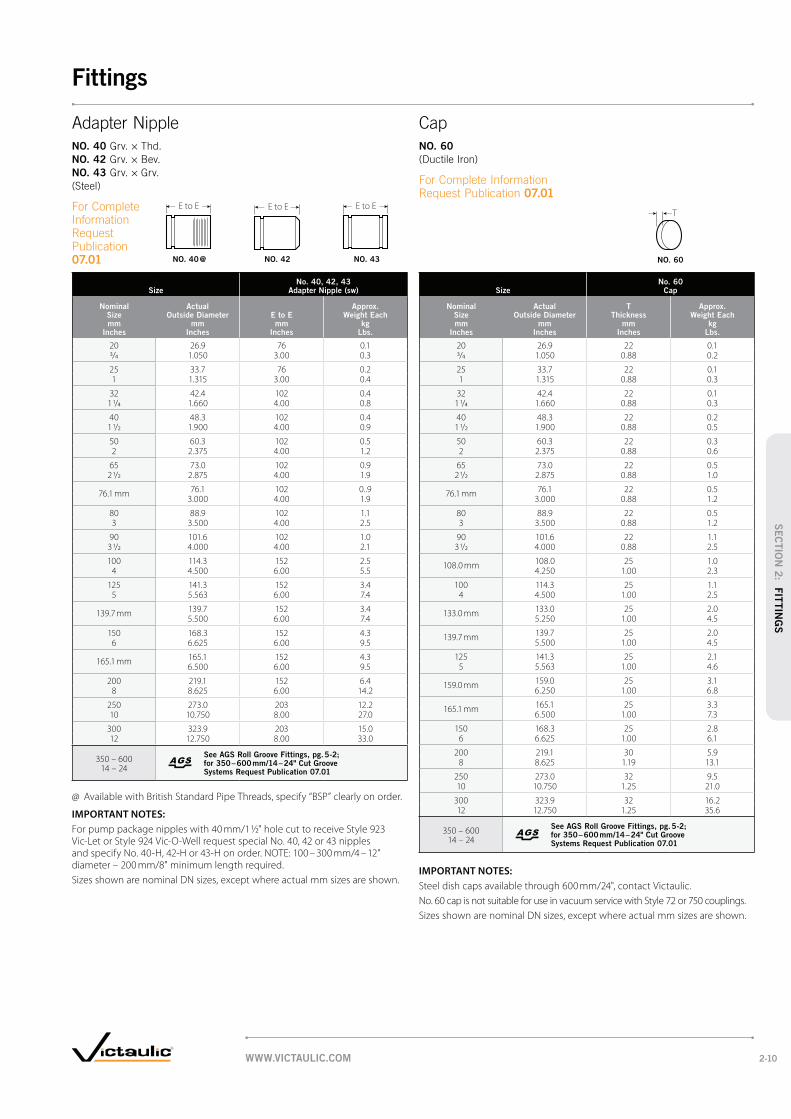
SizeNo. 40, 42, 43
Adapter Nipple (sw)
Nominal Size mm
Inches
Actual Outside Diameter
mm Inches
E to E mm
Inches
Approx. Weight Each
kg Lbs.
20 26.9 76 0.13/4 1.050 3.00 0.3
25 33.7 76 0.21 1.315 3.00 0.4
32 42.4 102 0.41 1/4 1.660 4.00 0.8
40 48.3 102 0.41 1/2 1.900 4.00 0.9
50 60.3 102 0.52 2.375 4.00 1.2
65 73.0 102 0.92 1/2 2.875 4.00 1.9
76.1 mm 76.1 102 0..93.000 4.00 1.9
80 88.9 102 1.13 3.500 4.00 2.5
90 101.6 102 1.03 1/2 4.000 4.00 2.1
100 114.3 152 2.54 4.500 6.00 5.5
125 141.3 152 3.45 5.563 6.00 7.4
139.7 mm 139.7 152 3.45.500 6.00 7.4
150 168.3 152 4.36 6.625 6.00 9.5
165.1 mm 165.1 152 4.36.500 6.00 9.5
200 219.1 152 6.48 8.625 6.00 14.2
250 273.0 203 12.210 10.750 8.00 27.0
300 323.9 203 15.012 12.750 8.00 33.0
350 – 600 14 – 24
See AGS Roll Groove Fittings, pg. 5-2; for 350 – 600 mm/14 – 24" Cut Groove Systems Request Publication 07.01
@ Available with British Standard Pipe Threads, specify “BSP” clearly on order.
IMPORTANT NOTES:
For pump package nipples with 40 mm/1 ½" hole cut to receive Style 923 Vic-Let or Style 924 Vic-O-Well request special No. 40, 42 or 43 nipples and specify No. 40-H, 42-H or 43-H on order. NOTE: 100 – 300 mm/4 – 12" diameter – 200 mm/8" minimum length required.
Sizes shown are nominal DN sizes, except where actual mm sizes are shown.
SizeNo. 60
Cap
Nominal Size mm
Inches
Actual Outside Diameter
mm Inches
T Thickness
mm Inches
Approx. Weight Each
kg Lbs.
20 26.9 22 0.13/4 1.050 0.88 0.2
25 33.7 22 0.11 1.315 0.88 0.3
32 42.4 22 0.11 1/4 1.660 0.88 0.3
40 48.3 22 0.21 1/2 1.900 0.88 0.5
50 60.3 22 0.32 2.375 0.88 0.6
65 73.0 22 0.52 1/2 2.875 0.88 1.0
76.1 mm 76.1 22 0.53.000 0.88 1.2
80 88.9 22 0.53 3.500 0.88 1.2
90 101.6 22 1.13 1/2 4.000 0.88 2.5
108.0 mm 108.0 25 1.04.250 1.00 2.3
100 114.3 25 1.14 4.500 1.00 2.5
133.0 mm 133.0 25 2.05.250 1.00 4.5
139.7 mm 139.7 25 2.05.500 1.00 4.5
125 141.3 25 2.15 5.563 1.00 4.6
159.0 mm 159.0 25 3.16.250 1.00 6.8
165.1 mm 165.1 25 3.36.500 1.00 7.3
150 168.3 25 2.86 6.625 1.00 6.1
200 219.1 30 5.98 8.625 1.19 13.1
250 273.0 32 9.510 10.750 1.25 21.0
300 323.9 32 16.212 12.750 1.25 35.6
350 – 600 14 – 24
See AGS Roll Groove Fittings, pg. 5-2; for 350 – 600 mm/14 – 24" Cut Groove Systems Request Publication 07.01
IMPORTANT NOTES:
Steel dish caps available through 600 mm/24", contact Victaulic.
No. 60 cap is not suitable for use in vacuum service with Style 72 or 750 couplings.
Sizes shown are nominal DN sizes, except where actual mm sizes are shown.
TE to E E to EE to E
NO. 40
NO. 42
NO. 43
07.01 NO. 42 NO. 43NO. 40 @ NO. 60
NO. 60
07.01
WWW.VICTAULIC.COM 2-10
Fittings
SEC
TIO
N 2
: FIT
TIN
GS

Size
No. 41 ANSI 125
Flange Adapter Nipple
No. 45F and No. 45R ANSI 150
Flange Adapter Nipple
No. 46F and No. 46R ANSI 300
Flange Adapter Nipple
Nominal Size mm
Inches
Actual Outside Diameter
mm Inches
E to E mm
Inches
Approx. Weight Each
kg Lbs.
E to E mm
Inches
Approx. Weight Each
kg Lbs.
E to E mm
Inches
Approx. Weight Each
kg Lbs.
20 26.9 76 1.0 76 1.0 76 1.53/4 1.050 3.00 2.3 3.00 2.3 3.00 3.3
25 33.7 76 1.1 76 1.2 76 1.81 1.315 3.00 2.5 3.00 2.7 3.00 3.9
32 42.4 102 1.4 102 1.5 102 2.21 1/4 1.660 4.00 3.0 4.00 3.3 4.00 4.8
40 48.3 102 1.6 102 1.8 102 3.11 1/2 1.900 4.00 3.5 4.00 3.9 4.00 6.9
50 60.3 102 2.5 102 2.8 102 3.72 2.375 4.00 5.5 4.00 6.2 4.00 8.2
65 73.0 102 3.6 102 4.5 102 5.42 1/2 2.875 4.00 8.0 4.00 9.9 4.00 11.9
80 88.9 102 4.3 102 5.2 102 7.53 3.500 4.00 9.5 4.00 11.4 4.00 16.5
90 101.6 102 5.4 102 6.8 102 9.13 1/2 4.000 4.00 12.0 4.00 15.1 4.00 20.1
100 114.3 152 7.6 152 8.3 152 12.44 4.500 6.00 16.7 6.00 18.4 6.00 27.4
125 141.3 152 9.8 152 9.7 152 16.05 5.563 6.00 21.5 6.00 21.3 6.00 35.3
150 168.3 152 12.0 152 12.5 152 21.56 6.625 6.00 26.5 6.00 27.5 6.00 47.5
200 219.1 152 17.7 152 18.8 152 31.98 8.625 6.00 39.0 6.00 41.3 6.00 70.3
250 273.0 203 25.9 203 27.1 203 45.710 10.750 8.00 57.0 8.00 59.8 8.00 100.8
300 323.9 203 18.6 203 40.0 203 66.312 12.750 8.00 41.0 8.00 88.2 8.00 146.2
350 – 600 14 – 24
See AGS Roll Groove Fittings, pg. 5-2; for 350 – 600 mm/14 – 24" Cut Groove Systems Request Publication 07.01
IMPORTANT NOTES:
Flanged adapter nipples are supplied with standard rolled grooves. Standard cut grooves or machining for rubber lining are optionally available. Contact Victaulic for details.
Sizes shown are nominal DN sizes, except where actual mm sizes are shown.
E to E E to EE to E E to E E to E
NO. 41
NO. 45F
NO. 45R
NO. 46F
NO. 46R
07.01
NO. 45F NO. 45RNO. 41 NO. 46F NO. 46R
WWW.VICTAULIC.COM2-11
Fittings
SEC
TIO
N 2
: F
ITTIN
GS

Size
No. 41-DN PN10
Flange Adapter Nipple
No. 41-DN PN16
Flange Adapter Nipple
Nominal Size mm
Inches
Actual Outside Diameter
mm Inches
E to E mm
Inches
Approx. Weight Each
kg Lbs.
E to E mm
Inches
Approx. Weight Each
kg Lbs.
DN50 60.3 102 + 102 +2 2.375 4.00 4.00
DN65 73.0 102 + 102 +2 1/2 2.875 4.00 4.00
DN65 76.1 mm102 + 102 +4.00 4.00
DN80 88.9 102 + 102 +3 3.500 4.00 4.00
DN90 101.6 102 + 102 +3 1/2 4.000 4.00 4.00
DN100 114.3 152 + 152 +4 4.500 6.00 6.00
DN125 139.7 mm152 + 152 +6.00 6.00
DN125 141.3 152 + 152 +5 5.563 6.00 6.00
DN150 165.1 mm152 + 152 +6.00 6.00
DN150 168.3 152 + 152 +6 6.625 6.00 6.00
DN200 219.1 152 + 152 +8 8.625 6.00 6.00
DN250 273.0 203 + 203 +10 10.750 8.00 8.00
DN300 323.9 203 + 203 +12 12.750 8.00 8.00
+ Contact Victaulic for details.
IMPORTANT NOTES:
Flanged adapter nipples are supplied with standard rolled grooves. Standard cut grooves or machining for rubber lining are optionally available. Contact Victaulic for details.
Sizes shown are nominal DN sizes, except where actual mm sizes are shown.
E to E E to E
NO. 41-DN
NO. 41-DN PN10 NO. 41-DN PN16
WWW.VICTAULIC.COM 2-12
Fittings
SEC
TIO
N 2
: FIT
TIN
GS

SizeNo. 80
Female Threaded Adapter
Nominal Size mm
Inches
Actual Outside Diameter
mm Inches
E to E mm
Inches
Approx. Weight Each
kg Lbs.
20 26.9 51 0.53/4 1.050 2.00 1.0
25 33.7 52 0.51 1.315 2.06 1.0
32 42.4 59 0.71 1/4 1.660 2.31 (sw) 1.5
40 48.3 59 0.71 1/2 1.900 2.31 (sw) 1.5
50 60.3 64 0.62 2.375 2.50 1.4
65 73.0 70 0.72 1/2 2.875 2.75 1.5
80 88.9 70 1.33 3.500 2.75 2.9
100 114.3 83 2.04 4.500 3.25 4.5
# Ductile iron except those marked (sw) which are segmentally welded steel.
@ Available with British Standard Pipe Threads, specify “BSP” clearly on order.
IMPORTANT NOTES:
Sizes shown are nominal DN sizes, except where actual mm sizes are shown.
SizeNo. 48
Hose Nipple
Nominal Size mm
Inches
Actual Outside Dia.
mm Inches
E to E mm
Inches
L mm
Inches
Approx. Weight Each
kg Lbs.
20 26.9 79 20 0.13/4 1.050 3.12 .78 0.3
25 33.7 86 26 0.21 1.315 3.38 1.03 0.4
32 42.4 98 33 0.31 1/4 1.660 3.88 1.28 0.6
40 48.3 98 39 0.41 1/2 1.900 3.88 1.53 0.8
50 60.3 114 52 0.52 2.375 4.50 2.03 1.1
65 73.0 137 64 0.92 1/2 2.875 5.38 2.53 2.0
80 88.9 146 77 1.53 3.500 5.75 3.03 3.2
100 114.3 178 102 2.24 4.500 7.00 4.03 4.9
125 141.3 222 128 3.65 5.563 8.75 5.03 8.0
150 168.3 257 153 6.56 6.625 10.12 6.03 14.3
200 219.1 302 204 11.28 8.625 11.88 8.03 24.7
250 273.0 318 255 18.210 10.750 12.50 10.03 40.1
300 323.9 368 306 28.112 12.750 14.50 12.03 62.0
IMPORTANT NOTES:
Sizes shown are nominal DN sizes, except where actual mm sizes are shown.
E to E
E to E
L
NO. 80
07.01
NO. 48
07.01
NO. 80 @ NO. 48
WWW.VICTAULIC.COM2-13
Fittings
SEC
TIO
N 2
: F
ITTIN
GS

SizeNo. 50
Concentric ReducerNo. 51
Eccentric Reducer
Nominal Size mm
Inches
E to E mm
Inches
Approx. Weight Each
kg Lbs.
E to E mm
Inches
Approx. Weight Each
kg Lbs.
32 × 20 + 0.9 — —1 1/4 3/4 1.9
25 + 0.9 — —1 1.9
40 × 20 + 0.6 — —1 1/2 3/4 1.4
25 64 0.4 216 2.01 2.50* 0.8 8.50 (sw) 4.5
32 64 0.5 — —1 1/4 2.50* 1.0
50 × 20 64 0.3 229 0.9 2 3/4 2.50* 0.9 9.00 (sw) 2.0
25 64 0.3 229 1.01 2.50* 0.7 9.00 (sw) 2.3
32 64 0.5 229 2.11 1/4 2.50* 1.2 9.00 (sw) 4.6
40 64 0.5 229 2.11 1/2 2.50* 1.0 9.00 (sw) 4.6
65 × 20 + 0.6 + 1.5 2 1/2 3/4 1.3 3.3
25 64 1.5 241 1.61 2.50 3.6 9.50 (sw) 3.5
32 64 1.5 241 +1 1/4 2.50* 3.3 9.50 (sw)
40 64 1.6 241 1.71 1/2 2.50* 3.6 9.50 (sw) 3.7
50 64 1.8 241 2.02 2.50 3.9 9.50 (sw) 4.3
76.1 × 25 64 0.8 241 1.21 2.50 1.7 9.50 (sw) 2.6
32 64 0.6 241 1.21 1/4 2.50 1.3 9.50 (sw) 2.6
40 64 0.6 241 1.51 1/2 2.50 1.3 9.50 (sw) 3.3
50 64 0.7 241 1.32 2.50 1.6 9.50 (sw) 2.8
80 × 20 + 0.7 + 2.0 3 3/4 1.5 4.5
25 64 0.6 241 2.21 2.50* 1.3 9.50 (sw) 4.8
32 + 1.4 + 2.21 1/4 3.0 4.8
40 64 2.3 241 2.31 1/2 2.50* 5.1 9.50 (sw) 5.1
50 64 0.7 89 2.72 2.50* 1.6 3.50 6.0
65 64 0.8 89 3.22 1/2 2.50* 1.8 3.50 7.0
76.1 64 1.0 — —2.50 2.1
SizeNo. 50
Concentric ReducerNo. 51
Eccentric Reducer
Nominal Size mm
Inches
E to E mm
Inches
Approx. Weight Each
kg Lbs.
E to E mm
Inches
Approx. Weight Each
kg Lbs.
90 × 80 64 0.9 241 3.23 1/2 3 2.50 2.0 9.50 (sw) 7.0
100 × 25 76 1.4 330 2.9 4 1 3.00* 3.0 13.00 (sw) 6.5
32 + 2.1 — —1 1/4 4.6
40 254 3.1 254 3.71 1/2 10.00 6.9 10.00 (sw) 8.1
50 76 1.1 102 1.52 3.00* 2.4 4.00 3.3
65 76 1.2 102 1.52 1/2 3.00* 2.7 4.00 3.4
76.176 1.2 — —
3.00* 2.7
80 76 1.4 102 1.63 3.00* 3.2 4.00 3.5
90 76 1.3 254 3.63 1/2 3.00 2.9 10.00 (sw) 8.0
125 × 50 279 4.1 279 2.45 2 11.00 9.0 11.00 (sw) 5.2
65 279 5.0 279 4.92 1/2 11.00 11.0 11.00 (sw) 10.8
80 102 2.5 279 5.03 4.00 5.5 11.00 (sw) 11.1
100 89 1.9 127 5.44 3.50 4.3 5.00 12.0
150 × 25 102 2.3 292 6.66 1 4.00* 5.0 11.50 (sw) 14.5
40 + 2.5 + +1 1/2 5.5
50 102 3.0 292 6.62 4.00* 6.6 11.50 (sw) 14.5
65 102 2.9 292 6.42 1/2 4.00* 6.4 11.50 (sw) 14.2
80 102 2.9 140 6.83 4.00* 6.4 5.50 15.0
100 102 2.9 140 7.74 4.00 6.5 5.50 17.0
125 102 2.9 140 7.75 4.00 6.4 5.50 17.0
TABLE CONTINUED ON PG. 2-15, SEE FOOTNOTES ON PG. 2-15
E to E
Eto E
NO. 51
NO. 50
NO. 51
07.01
NO. 50
WWW.VICTAULIC.COM 2-14
Fittings
SEC
TIO
N 2
: FIT
TIN
GS

SizeNo. 50
Concentric ReducerNo. 51
Eccentric Reducer
Nominal Size mm
Inches
E to E mm
Inches
Approx. Weight Each
kg Lbs.
E to E mm
Inches
Approx. Weight Each
kg Lbs.
TABLE CONTINUED FROM PG. 2-14
165.1 × 50 — 2.7 — —2 6.0
76.1 102 2.9 292 6.43 4.00 6.4 11.50 (sw) 14.2
80 102 2.7 — 3.13 4.00 6.0 6.8
100 102 2.7 — 3.254 4.00 6.0 7.2
139.7102 2.9 140 7.74.00 6.4 5.50 17.0
200 × 65 406 3.6 305 11.88 2 1/2 16.00* (sw) 7.9 12.00 (sw) 26.1
76.1406 3.6 305 11.8
16.00 7.9 12.00 (sw) 26.1
80 127 4.2 305 10.03 5.00 9.3 12.00 (sw) 22.0
100 127 4.8 305 10.44 5.00 10.4 12.00 (sw) 23.0
125 127 5.2 305 10.45 5.00 11.6 12.00 (sw) 23.0
150 127 5.4 152 10.96 5.00 11.9 6.00 24.0
165.1127 5.4 152 10.95.00 11.9 6.00 24.0
250 × 100 152 8.9 330 14.510 4 6.00 19.7 13.00 (sw) 32.0
125 + 15.6 + 15.75 34.3 34.6
150 152 9.1 330 16.76 6.00 20.0 13.00 (sw) 36.9
200 152 10.0 178 9.88 6.00 22.0 7.00 21.6
300 × 100 + 20.0 356 21.812 4 44.0 14.00 (sw) 48.0
150 178 11.2 356 22.76 7.00 24.6 14.00 (sw) 50.0
200 178 23.6 356 24.38 7.00 52.0 14.00 (sw) 53.5
250 178 17.7 356 25.910 7.00 39.0 14.00 (sw) 57.0
350 – 600 14 – 24
See AGS Roll Groove Fittings, pg. 5-2; for 350 – 600 mm/14 – 24" Cut Groove Systems Request Publication 07.01
+ Contact Victaulic for details.
* Available with male threaded small end No. 52.
# Ductile Iron except those marked (sw) which are segmentally welded steel.
IMPORTANT NOTES:
Steel eccentric reducers available through 750 mm/30", contact Victaulic.
Sizes shown are nominal DN sizes, except where actual mm sizes are shown.
E to E
Eto E
(cont'd)
NO. 50
NO. 51
07.01
NO. 50 NO. 51
WWW.VICTAULIC.COM2-15
Fittings
SEC
TIO
N 2
: F
ITTIN
GS

SizeNo. 52
Small Threaded ReducerNo. 52F
Small Threaded Reducer (BSPT)
Nominal Size mm
Inches
E to E mm
Inches
Approx. Weight Each
kg Lbs.
E to E mm
Inches
Approx. Weight Each
kg Lbs.
40 × 25 64 0.4— —
1 1/2 1 2.50 0.8
32 64 0.4— —
1 1/4 2.50 0.9
50 × 20 64 0.4— —
2 3/4 2.50 0.9
25 64 0.3— —
1 2.50 0.7
32 64 0.5— —
1 1/4 2.50 1.2
40 64 0.5— —
1 1/2 2.50 1.0
65 × 25 + (sw) 0.5 — —
2 1/2 3/4 1.0
32 64 0.5— —
1 1/4 2.50 (sw) 1.2
40 64 0.6— —
1 1/2 2.50 (sw) 1.3
50 76 0.6— —
2 3.00 1.4
76.1 † × 48.3 63.5 0.8 63.5 0.8
60.0 — — 63.5 0.9
80 × 20 + (sw) 0.7— —
3 3/4 1.5
25 64 0.6— —
1 2.50 1.3
40 64 0.7— —
1 1/2 2.50 (sw) 1.5
50 64 0.7 — —
2 2.50 1.5
65 64 1.1— —
2 1/2 2.50 2.4
88.9 † × 42.4 63.5 0.9 63.5 0.8
48.3 63.5 0.9 63.5 0.9
60.0 — — 63.5 0.9
100 × 25 76 1.0— —
4 1 3.00 2.3
40 + (sw) 1.1— —
1 1/2 2.5
50 76 1.2— —
2 3.00 2.6
65 76 1.2— —
2 1/2 3.00 2.6
80 76 1.1— —
3 3.00 2.5
SizeNo. 52
Small Threaded ReducerNo. 52F
Small Threaded Reducer (BSPT)
Nominal Size mm
Inches
E to E mm
Inches
Approx. Weight Each
kg Lbs.
E to E mm
Inches
Approx. Weight Each
kg Lbs.
108.0 † × 42.4 76.2 1.3 76.2 1.3
48.3 76.2 1.3 76.2 1.4
60.0 — — 76.2 1.4
114.3 † × 42.4 76.2 1.3 76.2 1.3
48.3 76.2 1.3 76.2 1.3
60.0 — — 76.2 1.4
125 × 100 + (sw) 2.0 — —5 4 4.5
133.0 † × 60.0 — — 114.3 2.2
139.0 † × 60.0 — — 114.3 2.3
150 × 25 102 2.5 — —6 1 4.00 5.5
50 102 2.6 — —2 4.00 5.7
65 102 2.6 — —2 1/2 4.00 5.8
80 102 2.6 — —3 4.00 5.8
100 + (sw) 2.9 — —4 6.5
125 + (sw) 7.9 — —5 17.5
159.0 † × 42.4 114.3 2.2 114.3 2.5
48.3 114.3 2.2 114.3 2.5
60.0 — — 114.3 2.6
165.1 † × 42.4 101.6 2.4 101.6 2.9
48.3 101.6 2.6 101.6 3.0
60.0 — — 101.6 3.0
200 × 50 + (sw) 0.7 — —8 2 1.5
65 406 0.8— —
2 1/2 16.00 1.7
+ Contact Victaulic for details.
# Ductile iron except those marked (sw) which are segmentally welded steel.
† Available in metric sizes only.
IMPORTANT NOTES:
Sizes shown are nominal DN sizes, except where actual mm sizes are shown.
Eto E
Eto E
NO. 52
NO. 52F
07.01
NO. 52 NO. 52F
WWW.VICTAULIC.COM 2-16
Fittings
SEC
TIO
N 2
: FIT
TIN
GS
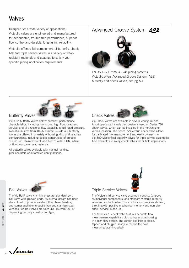
Designed for a wide variety of applications,
Victaulic valves are engineered and manufactured
for dependable, trouble-free performance, superior
flow control and durable, long-lasting reliability.
Victaulic offers a full complement of butterfly, check,
ball and triple service valves in a variety of wear-
resistant materials and coatings to satisfy your
specific piping application requirements.
Advanced Groove System
For 350 – 600 mm/14 – 24" piping systems
Victaulic offers Advanced Groove System (AGS)
butterfly and check valves, see pg. 5-1.
Check Valves
Vic-Check valves are available in several configurations.
A spring-assisted, single disc design is used on Series 716
check valves, which can be installed in the horizontal or
vertical position. The Series 779 Venturi check valve allows
for calibrated flow measurement and easily connects to
Vic-300 MasterSeal butterfly valves for triple service assemblies.
Also available are swing check valves for oil field applications.
Ball Valves
The Vic-Ball® valve is a high-pressure, standard-port
ball valve with grooved ends. Its internal design has been
streamlined to provide excellent flow characteristics,
and comes available in ductile iron and stainless steel
versions. Vic-Ball valves are sized 40 – 150 mm/1½ – 6"
depending on body construction type.
Butterfly Valves
Victaulic butterfly valves deliver excellent performance
characteristics, including low torque, high flow, dead-end
service, and bi-directional flow capability to full rated pressure.
Available in sizes from 40 – 600 mm/1½ – 24", our butterfly
valves are offered in a variety of housing, disc and seat seal
configurations, including bodies constructed of durable
ductile iron, stainless steel, and bronze with EPDM, nitrile,
or fluoroelastomer seat materials.
All butterfly valves available with manual handles,
gear operators or automated configurations.
Triple Service Valves
The Victaulic tri-service valve assembly consists (shipped
as individual components) of a standard Victaulic butterfly
valve and a check valve. This combination provides shut-off,
throttling with positive mechanical memory and non-slam
check service in one unit.
The Series 779 check valve features accurate flow
measurement capabilities plus spring assisted closing
in a high flow design. The venturi-like inlet is drilled,
tapped and plugged, ready to receive the flow
measuring taps (included).
WWW.VICTAULIC.COM3-1
Valves
SEC
TIO
N 3
: V
ALVE
S

Valve Type Building Services
IndustrialWater and Wastewater
Mining Oil Field Plumbing
BUTTERFLY VALVES
CHECK VALVES
BALL VALVES
TRIPLE SERVICE VALVES
FLOW REGULATING VALVES
PRODUCTS
1-12 Couplings
2-1 Fittings
3-1 Valves
4-1 Accessories
5-1 Advanced Groove System
6-1 Hole Cut Piping System
7-1 Plain End Piping System
8-1 Grooved System for
Stainless Steel Pipe
9-1 Plain End Piping System
for HDPE Pipe
10-1 Grooved Copper
11-1 Depend-O-Lok System
12-1 Gaskets
13-1 Pipe Preparation Tools
14-1 Product Index
15-1 Piping Software
Valve Application Guide
BUTTERFLY VALVES
3-3 Vic®-300 MasterSeal™
3-6 Series 700
3-7 Series 706
8-11 Series 763 Stainless Steel
10-8 Series 608 Copper
CHECK VALVES
3-10 Series 716
3-11 Series 779
3-12 Series 712
3-12 Series 713
BALL VALVES
3-15 Series 726
8-10 Series 726S Stainless Steel
TRIPLE SERVICE VALVES
3-9 Butterfly/Check Combo
FLOW REGULATING VALVES
3-13 Series 7890
3-14 Series 7340
Flow Regulating Valves
Series 7890 DRV (double regulating and commissioning
valves) balance the flow of hot and cold water to provide
uniform heating and cooling distribution.
Series 7340 Grooved End Metering Station provides
an economical way to obtain flow measurements
in HVAC systems.
WWW.VICTAULIC.COM 3-2
Valves
SEC
TIO
N 3
: VA
LVE
S

Size DimensionsApprox.
Wgt. Each
Nominal Size mm
Inches
Actual Outside Dia.
mm Inches
A mm
Inches
B mm
Inches
C mm
Inches
D mm
Inches
E mm
Inches
F mm
Inches
G mm
Inches
H mm
Inches
J mm
Inches
K mm
Inches
L mm
Inches
M mm
Inches
N mm
Inches
P mm
Inches
Q-Key mm
Inches
Bare kg
Lbs.
50 60.3 81.5 82.6 36.6 — — 46.0 96.8 55.2 3.3 8.6 70.0 22.4 8.0 11.0 — 1.62 2.375 3.21 3.25 1.44 1.81 3.81 2.17 0.13 0.34 2.756 0.88 0.32 0.43 3.5
65 73.0 95.8 101.6 45.0 — — 53.3 108.0 55.2 3.3 8.6 70.0 22.4 8.0 11.0 — 2.32 1/2 2.875 3.77 4.00 1.77 2.10 4.25 2.17 0.13 0.34 2.756 0.88 0.32 0.43 5.0
76.1 mm76.1 95.8 101.6 45.0 — — 53.3 108.0 55.2 3.3 8.6 70.0 22.4 8.0 11.0 — 2.3
3.000 3.77 4.00 1.77 2.10 4.25 2.17 0.13 0.34 2.756 0.88 0.32 0.43 5.0
80 88.9 95.8 114.3 45.0 — — 59.7 114.3 55.2 3.3 8.6 70.0 22.4 8.0 11.0 — 2.73 3.500 3.77 4.50 1.77 2.35 4.50 2.17 0.13 0.34 2.756 0.88 0.32 0.43 6.0
108.0 mm †108.0 117.6 139.7 55.8 — — 73.2 133.4 55.2 3.3 8.6 70.0 22.6 11.0 15.0 — 4.24.250 4.63 5.50 2.20 2.88 5.25 2.17 0.13 0.34 2.756 0.89 0.43 0.59 9.3
100 114.3 117.6 139.7 55.4 — — 73.2 133.4 55.2 3.3 8.6 70.0 22.6 11.0 15.0 — 4.24 4.500 4.63 5.50 2.18 2.88 5.25 2.17 0.13 0.34 2.756 0.89 0.43 0.59 9.3
133.0 mm †133.0 149.4 160.0 65.5 — — 84.8 158.8 55.2 3.3 8.6 70.0 28.5 12.7 19.1 — 7.65.250 5.88 6.30 2.58 3.34 6.25 2.17 0.13 0.34 2.756 1.12 0.50 0.75 16.8
139.7 mm139.7 149.4 160.0 65.5 — — 84.8 158.8 55.2 3.3 8.6 70.0 28.5 12.7 19.1 — 7.65.500 5.88 6.30 2.58 3.34 6.25 2.17 0.13 0.34 2.756 1.12 0.50 0.75 16.8
125 141.3 149.4 160.0 65.5 — — 84.8 158.8 55.2 3.3 8.6 70.0 28.5 12.7 19.1 — 7.65 5.563 5.88 6.30 2.58 3.34 6.25 2.17 0.13 0.34 2.756 1.12 0.50 0.75 16.8
159.0 mm †159.0 149.4 185.4 65.5 10.6 — 97.3 171.5 55.2 3.3 8.6 70.0 28.5 12.7 19.1 — 9.16.250 5.88 7.30 2.58 0.42 3.83 6.75 2.17 0.13 0.34 2.756 1.12 0.50 0.75 20.0
165.1 mm165.1 149.4 185.4 65.5 10.6 — 97.3 171.5 55.2 3.3 8.6 70.0 28.5 12.7 19.1 — 9.16.500 5.88 7.30 2.58 0.42 3.83 6.75 2.17 0.13 0.34 2.756 1.12 0.50 0.75 20.0
150 168.3 149.4 185.4 65.5 10.6 — 97.3 171.5 55.2 3.3 8.6 70.0 28.5 12.7 19.1 — 9.16 6.625 5.88 7.30 2.58 0.42 3.83 6.75 2.17 0.13 0.34 2.756 1.12 0.50 0.75 20.0
200 219.1 135.4 254.0 59.2 37.4 20.3 127.0 203.2 55.2 3.3 8.6 70.0 33.0 — 22.2 4.8 15.68 8.625 5.33 10.00 2.33 1.47 0.80 5.00 8.00 2.17 0.13 0.34 2.756 1.30 0.88 0.188 34.3
250 273.0 162.6 311.2 76.2 45.9 35.8 155.7 247.7 70.1 3.3 11.0 102.0 57.2 — 31.8 7.9 32.710 10.750 6.40 12.25 3.00 1.81 1.41 6.13 9.75 2.76 0.13 0.43 4.016 2.25 1.25 0.312 72.0
300 323.9 165.1 362.0 76.2 71.0 58.4 181.1 273.1 70.1 3.3 11.0 102.0 56.9 — 31.8 7.9 39.912 12.750 6.50 14.25 3.00 2.80 2.30 7.13 10.75 2.76 0.13 0.43 4.016 2.24 1.25 0.312 88.0
350 – 600 14 – 24
See Vic-300 AGS Butterfly Valve, pg. 5-11, Request Publication 20.06
† Contact Victaulic for availability.
IMPORTANT NOTES:
50 – 200 mm/2 – 8" sizes are ISO Flange Designation F07; 250 mm/10" and 300 mm/12" sizes are ISO Flange Designation F10.
See pg. 3-5 for flow coefficient.
Sizes shown are nominal DN sizes, except where actual mm sizes are shown.
H
M
JD
G
F
A BC
Q Key
4 x KL
P
E
B
View B-BMounting Flange for
200 – 300 mm/8 – 12"Valve shown inopen position
B
D
G
F
ABC
A A
P
L 4 x K
N
N
View A-AMounting Flange for50 – 150 mm/2 – 6”
Valve shown inopen position
Vic-300 MasterSeal Butterfly Valve
For Complete Information Request Publication 08.20
body seals equally on both sides of the valve
keeps torque consistent over the life of the valve
to the full pressure rated up to 2065 kPa/300 psi
mm/2 – 12"
BARE VALVE
TYPICAL 50 – 150 mm/2 – 6" SIZES
BARE VALVE
TYPICAL 200 – 300 mm/8 – 12" SIZES
MOUNTING FLANGE RECESS
Patent Pending
WWW.VICTAULIC.COM3-3
SEC
TIO
N 3
: V
ALVE
S
Valves – Butterfly Valves

Size DimensionsApprox.
Weight Each
Nominal Size mm
Inches
Actual Outside Dia.
mm Inches
A End to End
T-R mm
Inches
U mm
Inches
Bare kg
Lbs.
Valve with 10 Position Handle
kg /Lbs.
Valve with Lever Handle
kg/Lbs.
50 60.3 81.5 177.8 39.9 1.6 2.0 2.72 2.375 3.21 7.00 1.57 3.5 4.4 6.0
65 73.0 95.8 177.8 39.9 2.3 2.7 3.42 1/2 2.875 3.77 7.00 1.57 5.0 5.9 7.5
76.1 mm 76.1 95.8 177.8 39.9 2.3 2.7 3.43.000 3.77 7.00 1.57 5.0 5.9 7.5
80 88.9 95.8 177.8 39.9 2.7 3.1 3.93 3.500 3.77 7.0 1.57 6.0 6.9 8.5
108.0 mm †108.0 117.6 215.9 41.7 4.2 4.9 5.44.250 4.63 8.50 1.64 9.3 10.8 11.8
100 114.3 117.6 215.9 41.7 4.2 4.9 5.44 4.500 4.63 8.50 1.64 9.3 10.8 11.8
133.0 mm †133.0 149.4 304.8 41.7 7.6 8.5 9.15.250 5.88 12.00 1.64 16.8 18.8 20.0
139.7 mm 139.7 149.4 304.8 41.7 7.6 8.5 9.15.500 5.88 12.00 1.64 16.8 18.8 20.0
125 141.3 149.4 304.8 41.7 7.6 8.5 9.15 5.563 5.88 12.00 1.64 16.8 18.8 20.0
159.0 mm †159.0 149.4 304.8 41.7 9.1 10.0 10.56.250 5.88 12.00 1.64 20.0 22.0 23.2
165.1 mm 165.1 149.4 304.8 41.7 9.1 10.0 10.56.500 5.88 12.00 1.64 20.0 22.0 23.2
150 168.3 149.4 304.8 41.7 9.1 10.0 10.56 6.625 5.88 12.00 1.64 20.0 22.0 23.2
200 219.1 135.4 355.6 38.4 15.6 — 17.08 8.625 5.33 14.00 1.51 34.3 37.5
250 273.0 162.6 296.2 114.30 32.7 — 38.110 10.750 6.40 11.66 4.50 72.0 84.0
300 323.9 165.1 296.2 114.3 39.9 — 45.412 12.750 6.50 11.66 4.50 88.0 100.0
350 – 600 14 – 24
See Vic-300 AGS Butterfly Valve, pg. 5-11, Request Publication 20.06
† Contact Victaulic for availability.
IMPORTANT NOTES:
50 – 200 mm/2 – 8" sizes are ISO Flange Designation F07; 250 mm/10" and 300 mm/12" sizes are ISO Flange Designation F10.
See pg. 3-5 for flow coefficient.
Sizes shown are nominal DN sizes, except where actual mm sizes are shown.
U
T-R
A
SHUT
OPEN
U
T-R
A
U
(20" extended)
A
T-R
Vic-300 MasterSeal Butterfly Valve
WITH HANDLE
For Complete Information Request Publication 08.20
VALVE WITH LEVER LOCK HANDLE AND MEMORY STOP
TYPICAL 200 mm/8" SIZES
10-POSITION HANDLE WITH MEMORY STOP
TYPICAL 50 – 150 mm/2 – 6" SIZES
VALVE WITH LEVER LOCK HANDLE AND MEMORY STOP
TYPICAL 250 & 300 mm/10 & 12" SIZES
WWW.VICTAULIC.COM 3-4
SEC
TIO
N 3
: VA
LVE
S
Valves – Butterfly Valves

Size DimensionsApprox.
Weight Each Flow Coefficient@ (Fully Open)
KV Values
C V Values
Nominal Size mm
Inches
Actual Outside Dia.
mm Inches
A End to End
T mm
Inches
U mm
Inches
V mm
Inches
W mm
Inches
X mm
Inches
Y mm
Inches
Bare kg
Lbs.
Valve with Gear Operator
kg /Lbs.
50 60.3 81.5 40.1 112.5 173.7 44.5 92.5 100.1 1.6 2.7 99.52 2.375 3.21 1.58 4.43 6.84 1.75 3.64 3.94 3.5 6.0 115
65 73.0 95.8 40.1 112.5 184.9 44.5 92.5 100.1 2.3 3.4 224.92 1/2 2.875 3.77 1.58 4.43 7.28 1.75 3.64 3.94 5.0 7.5 260
76.1 mm 76.1 95.8 40.1 112.5 184.9 44.5 92.5 100.1 2.3 3.4 224.93.000 3.77 1.58 4.43 7.28 1.75 3.64 3.94 5.0 7.5 260
80 88.9 95.8 40.1 112.5 191.3 44.5 92.5 100.1 2.7 3.9 380.63 3.500 3.77 1.58 4.43 7.53 1.75 3.64 3.94 6.0 8.5 440
108.0 mm †108.0 117.6 40.1 112.5 210.3 44.5 92.5 100.1 4.2 5.4 709.34.250 4.63 1.58 4.43 8.28 1.75 3.64 3.94 9.3 11.8 820
100 114.3 117.6 40.1 112.5 210.3 44.5 92.5 100.1 4.2 5.4 709.34 4.500 4.63 1.58 4.43 8.28 1.75 3.64 3.94 9.3 11.8 820
133.0 mm †133.0 149.4 50.0 122.9 249.2 57.9 112.5 125.0 7.6 9.4 1038.05.250 5.88 1.97 4.84 9.81 2.28 4.43 4.92 16.8 20.8 1200
139.7 mm 139.7 149.4 50.0 122.9 249.2 57.9 112.5 125.0 7.6 9.4 1038.05.500 5.88 1.97 4.84 9.81 2.28 4.43 4.92 16.8 20.8 1200
125 141.3 149.4 50.0 122.9 249.2 57.9 112.5 125.0 7.6 9.4 1038.05 5.563 5.88 1.97 4.84 9.81 2.28 4.43 4.92 16.8 20.8 1200
159.0 mm †159.0 149.4 50.0 122.9 261.9 57.9 112.5 125.0 9.1 10.9 1557.06.250 5.88 1.97 4.84 10.31 2.28 4.43 4.92 20.0 24.0 1800
165.1 mm 165.1 149.4 50.0 122.9 261.9 57.9 112.5 125.0 9.1 10.9 1557.06.500 5.88 1.97 4.84 10.31 2.28 4.43 4.92 20.0 24.0 1800
150 168.3 149.4 50.0 122.9 261.9 57.9 112.5 125.0 9.1 10.9 1557.06 6.625 5.88 1.97 4.84 10.31 2.28 4.43 4.92 20.0 24.0 1800
200 219.1 135.4 50.0 122.9 293.6 57.9 112.5 125.0 15.6 17.4 2941.08 8.625 5.33 1.97 4.84 11.56 2.28 4.43 4.92 34.3 38.3 3400
250 273.0 162.6 73.2 197.1 384.3 82.6 160.0 199.9 32.7 39.0 5017.010 10.750 6.40 2.88 7.76 15.13 3.25 3.60 7.87 72.0 81.5 5800
300 323.9 165.1 73.2 197.1 409.7 82.6 160.0 199.9 39.9 44.2 7785.012 12.750 6.50 2.88 7.76 16.13 3.25 6.30 7.87 88.0 97.5 900.0
350 – 600 14 – 24
See Vic-300 AGS Butterfly Valve, pg. 5-11, Request Publication 20.06
@ KV/C
V values for flow of water at
+ 16°C/60°F with valve fully open.
† Contact Victaulic for availability.
IMPORTANT NOTES:
50 – 200 mm/2 – 8" sizes are ISO Flange Designation F07; 250 mm/10" and 300 mm/12" sizes are ISO Flange Designation F10.
Sizes shown are nominal DN sizes, except where actual mm sizes are shown.
Size DimensionsApprox.
Weight Each
Nominal Size
Inches mm
Sprocket Size
Chain Wheel Size (Dia.)
Inches mm
A Inches
mm
Lbs. kg
50 – 100 0 10 118 0.92 – 4 4.00 4.63 2.0
125 – 200 1 146 162 1.85 – 8 5.75 6.38 4.0
250 – 300 2 229 267 4.510 – 12 9.00 10.50 10.0
IMPORTANT NOTES:
Chain wheels are mounted to the gear operator hand wheels. Sprocket rim and guide arms are made of cast aluminum and chain is galvanized steel.
Always specify length of chain required. For insulation and locking device, contact Victaulic for details.
Sizes shown are nominal DN sizes, except where actual mm sizes are shown.
A
CHAIN WHEEL AND GUIDE
FOR GEAR OPERATED
BUTTERFLY VALVES
Y
V
XW
UT
A
Y
V
X
A
W
UT
Vic-300 MasterSeal Butterfly Valve
WITH GEAR OPERATOR
For Complete Information Request Publication 08.20
VALVE WITH GEAR OPERATOR
TYPICAL 50-150 mm/2-6" SIZES
VALVE WITH GEAR OPERATOR
TYPICAL 200 – 300 mm/8 – 12" SIZES
WWW.VICTAULIC.COM3-5
SEC
TIO
N 3
: V
ALVE
S
Valves – Butterfly Valves

STANDARD PROFILE BUTTERFLY VALVE
Size DimensionsApprox.
Wgt. Each † Flow Coefficient@ (Fully Open)
KV Values
C V Values
Nominal Size mm
Inches
Actual Outside Dia.
mm Inches
A End to End
mm Inches
B mm
Inches
C mm
Inches
D mm
Inches
F mm
Incheskg
Lbs.
40 48.3 86 113 41 72 92 1.3 31.11 1/2 1.900 3.38 4.45 1.63 2.82 3.63 2.8 36
50 60.3 81 126 48 78 105 1.5 60.62 2.375 3.19 4.97 1.88 3.09 4.06 3.3 70
65 73.0 97 157 64 94 124 2.9 103.82 1/2 2.875 3.81 6.19 2.50 3.69 4.88 6.4 120
80 88.9 97 171 70 102 143 3.1 155.73 3.500 3.81 6.75 2.75 4.00 5.63 6.8 180
100 114.3 116 208 89 119 178 5.5 449.84 4.500 4.56 8.19 3.50 4.69 7.00 12.1 520
125 141.3 148 237 102 136 216 11.8 692.05 5.563 5.81 9.34 4.00 5.34 8.50 26.1 800
165.1 mm 165.1 148 264 114 149 241 13.8 1124.56.500 5.81 10.38 4.50 5.88 9.50 30.5 1300
150 168.3 148 264 114 149 241 14.7 1124.56 6.625 5.81 10.38 4.50 5.88 9.50 32.5 1300
LOW PROFILE BUTTERFLY VALVE
40 48.3 86 91 41 50 100 1.3 31.11 1/2 1.900 3.38 3.57 1.63 1.95 3.93 2.8 36
50 60.3 81 104 48 56 110 1.5 60.62 2.375 3.20 4.09 1.88 2.22 4.33 3.3 70
65 73.0 97 132 64 64 134 2.9 103.82 1/2 2.875 3.81 5.19 2.50 2.50 5.27 6.4 120
80 88.9 97 146 70 76 154 3.1 155.73 3.500 3.81 5.75 2.75 3.00 6.05 6.8 180
100 114.3 116 188 89 99 181 5.5 449.84 4.500 4.56 7.38 3.50 3.88 7.11 12.1 520
125 141.3 148 225 102 123 232 11.8 692.05 5.563 5.81 8.84 4.00 4.84 9.14 26.1 800
165.1 mm 165.1 148 251 114 137 256 13.8 1124.56.500 5.81 9.88 4.50 5.38 10.08 30.5 1300
150 168.3 148 251 114 137 256 14.7 1124.56 6.625 5.81 9.88 4.50 5.38 10.08 32.5 1300
† Without operator or linkage.
@ KV/C
V values for flow of water at +16°C/60°F with valve fully open.
IMPORTANT NOTES:
Sizes shown are nominal DN sizes, except where actual mm sizes are shown.
F A
D
C
B
Butterfly Valve
SERIES 700
For Complete Information Request Publication 08.05
pressure drop performance
or low-profile body
shut-off
services to +110°C/+230°F
+82°C/+180°F liners
standard disc is aluminum
bronze (also available in
316 stainless steel)
operators available (request
08.05 for handle details
and performance)
shut-off for pressure rated
up to 1400 kPa/200 psi
40 – 150 mm/1½ – 6"
STANDARD PROFILE
TYPICAL FOR ALL SIZES
WWW.VICTAULIC.COM 3-6
SEC
TIO
N 3
: VA
LVE
S
Valves – Butterfly Valves

SERIES 706 BUTTERFLY VALVE WITHOUT GEAR OPERATOR
Size Dimensions
Approx. Wgt. Each
Actual Outside
Diameter mm
Inches
A End to End mm
Inches
B Overall Height
mm Inches
Mounting †
Nominal Size mm
Inches
C mm
Inches
D mm
Inches
E mm
Inches
F mm
Inches
G mm
Inches
H1 Dia.
mm Inches
H2 Dia.
mm Inches
I Dia. mm
Inches
w/o Oper.
kg Lbs.
350 355.6 178 621 246 327 68 406 375 127 14 35 56.714 14.000 7.00 24.45 9.68 12.89 2.66 16.00 14.77 5.00 0.563 1.38 125.0
377.0 mm377.0 254 621 246 327 29 406 375 126 15 35 56.7
14.843 10.00 24.45 9.68 12.89 1.16 16.00 14.77 4.96 0.578 1.38 125.0
400 406.4 178 689 278 358 93 457 412 127 14 38 69.416 16.000 7.00 27.14 10.94 14.10 3.66 18.00 16.20 5.00 0.563 1.50 153.0
426.0 mm426.0 267 689 278 358 48 457 412 126 15 38 69.4
16.772 10.50 27.14 10.94 14.10 1.90 18.00 16.20 4.96 0.578 1.50 153.0
450 457.0 203 751 313 381 105 508 438 127 14 45 90.318 18.000 8.00 29.56 12.31 15.00 4.15 20.00 17.25 5.00 0.563 1.75 199.0
480.0 mm480.0 279 751 313 381 59 508 438 126 15 45 90.318.898 11.00 29.56 12.31 15.00 2.64 20.00 17.25 4.96 0.578 1.75 199.0
500 508.0 216 829 357 409 125 584 472 152 14 51 129.320 20.000 8.50 32.64 14.06 16.10 4.93 23.00 18.58 6.00 0.563 2.00 285.0
530.0 mm530.0 292 829 357 409 87 584 472 140 17 51 129.3
20.866 11.50 32.64 14.06 16.10 3.42 23.00 18.58 5.51 0.672 2.00 285.0
600 610.0 254 988 408 511 157 678 580 152 14 57 204.624 24.000 10.00 38.89 16.06 20.10 6.18 26.70 22.83 6.00 0.563 2.25 451.0
630.0 mm630.0 305 988 408 511 131 678 580 165 21 57 204.6
24.803 12.00 38.89 16.06 20.10 5.17 26.70 22.83 6.50 0.844 2.25 451.0
† Mounting Key: 350 mm/14" – 3⁄8 Sq. × 1 7⁄8; 400 mm/16" – 3⁄8 Sq. × 2 1⁄2; 450 mm/18" – (2) 3⁄8 Sq. × 2; 500 mm/20" – (2) 1⁄2 Sq. × 2 1⁄4; 600 mm/24" – (2) 5⁄8 Sq. × 3
IMPORTANT NOTES:
Dimensions provided without operator are for sizing data only. Series 706 butterfly valves should never be installed without operators.
Sizes shown are nominal DN sizes, except where actual mm sizes are shown.
C
F
G
B
E A E
H1 Dia.
(BOLT CIRCLE)
H2 Dia.
(4 places)
I Dia.
D
cumbersome multi-bolt
wafer, lug type or flange
valves
or electric, pneumatic and
hydraulic actuators
2065 kPa/300 psi
350 – 630 mm/14 – 24"
Groove System components
Butterfly Valve
SERIES 706
For Complete Information Request Publication 08.17
TYPICAL FOR ALL SIZES WITHOUT GEAR OPERATOR
WWW.VICTAULIC.COM3-7
SEC
TIO
N 3
: V
ALVE
S
Valves – Butterfly Valves
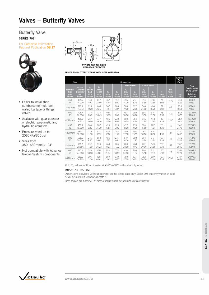
SERIES 706 BUTTERFLY VALVE WITH GEAR OPERATOR
Size Dimensions
Approx. Wgt. Each
Flow Coefficient@ (Fully Open)
KV Values
C V Values
Actual Outside
Diameter mm
Inches
A End to End mm
Inches
B Overall Height
mm Inches
Handwheel Chain Wheel
Nominal Size mm
Inches
G mm
Inches
K mm
Inches
N1
Dia.
mm Inches
O1
mm Inches
N2
Dia.
mm Inches
O2
mm Inches
T mm
Inches
No. Turns
to Close
kg Lbs.
350 355.6 178 657 367 152 356 217 394 318 77 6.75 68.9 8096.414 14.000 7.00 25.86 14.44 6.00 14.00 8.56 15.50 12.50 3.02 152.0 9360
377.0 mm377.0 254 665 367 200 500 327 546 406 77 9.5 70.8 8096.4
14.843 10.00 26.17 14.54 7.87 19.70 12.86 21.50 16.00 3.02 156.0 9360
400 406.4 178 723 403 178 457 259 394 318 86 7.75 84.8 10726.016 16.000 7.00 28.45 15.85 7.00 18.00 10.20 15.50 12.50 3.38 187.0 12400
426.0 mm426.0 267 737 406 220 500 364 546 444 86 13.75 91.2 10726.0
16.772 10.50 29.00 15.99 8.66 19.70 14.34 21.50 17.47 3.38 201.0 12400
450 457.0 203 787 429 229 457 259 394 287 111 11 116.6 13753.518 18.000 8.00 31.00 16.87 9.00 18.00 10.20 15.50 11.31 4.38 257.0 15900
480.0 mm480.0 279 817 436 285 700 395 762 474 111 21 122.2 13753.5
18.898 11.00 32.17 17.17 11.22 27.60 15.55 30.00 18.68 4.38 269.5 15900
500 508.0 216 864 456 275 610 300 394 313 137 11 161.0 17127.020 20.000 8.50 34.01 17.97 10.82 24.00 11.82 15.50 12.31 5.38 355.0 19800
530.0 mm530.0 292 920 464 285 700 468 762 549 137 52 174.3 17127.0
20.866 11.50 36.23 18.27 11.22 27.60 18.43 30.00 21.60 5.38 384.2 19800
600 610.0 254 1016 558 275 610 300 394 313 137 18 236.8 24998.524 24.000 10.00 40.01 21.97 10.82 24.00 11.82 15.50 12.31 5.38 522.0 28900
630.0 mm630.0 305 1017 569 370 700 521 762 599 137 79.25 274.4 24998.5
24.803 12.00 42.41 22.42 14.57 27.60 20.51 30.00 23.60 5.38 605.0 28900
@ KV/C
V values for flow of water at +16°C/+60°F with valve fully open.
IMPORTANT NOTES:
Dimensions provided without operator are for sizing data only. Series 706 butterfly valves should never be installed without operators.
Sizes shown are nominal DN sizes, except where actual mm sizes are shown.
A
O1
K
T N1
Dia.N2
Dia.
O2D
C
F
G
B
cumbersome multi-bolt
wafer, lug type or flange
valves
or electric, pneumatic and
hydraulic actuators
2065 kPa/300 psi
350 – 630 mm/14 – 24"
Groove System components
Butterfly Valve
SERIES 706
For Complete Information Request Publication 08.17
TYPICAL FOR ALL SIZES WITH GEAR OPERATOR
WWW.VICTAULIC.COM 3-8
SEC
TIO
N 3
: VA
LVE
S
Valves – Butterfly Valves

TRIPLE SERVICE BUTTERFLY/CHECK VALVE ASSEMBLY
Size DimensionsApprox.
Weight Each
Actual Outside
Diameter mm
Inches
Center to Top
Nominal Size mm
Inches
Handle mm
Inches
Gear mm
Inches
Center to Bottom
mm Inches
End to End mm
Inches
Manual Handle
kg Lbs.
Gear Operator
kg Lbs.
65 73.0 143 170 54 197 5.3 5.82 1/2 2.875 5.62 6.72 2.13‡ 7.75 11.6 12.7
76.1 mm76.1 149 185 54 197 6.2 6.2
3.000 5.88 7.25 2.13‡ 7.75 13.7 13.7
80 88.9 143 178 64 206 6.1 6.63 3.500 5.62 7.02 2.50‡ 8.12 13.5 14.6
100 114.3 193 205 102 365 16.8 18.24 4.500 7.62 8.08 4.00 14.38 37.0 40.1
139.7 mm139.7 200 249 117 419 21.5 21.95.500 7.88 9.81 4.62 16.50 47.4 48.2
125 141.3 206 218 117 419 23.6 25.05 5.563 8.12 8.60 4.62 16.50 52.0 55.0
165.1 mm165.1 213 262 127 444 27.0 27.46.500 8.38 10.31 5.00 17.50 59.5 60.3
150 168.3 219 269 127 444 31.3 32.76 6.625 8.62 10.58 5.00 17.50 69.0 72.0
200 219.1 267 318 155 495 56.7 56.78 8.625 10.50 12.50 6.12 19.50 125.0 125.0
250 273.0 — 357 182 597 — 84.810 10.750 14.05 7.18 23.50 187.0
300 323.9 — 390 206 663 — 117.912 12.750 15.37 8.12 26.12 260.0
‡ Based on Style 77 couplings. When using Style 07 dimensions are 49 mm/1.94" for 65 mm/2 ½" size and 57 mm/2.25" for 80 mm/3" size.
IMPORTANT NOTES:
Sizes shown are nominal DN sizes, except where actual mm sizes are shown.
C to TopC to
Bottom
E to E
C to TopC to
Bottom
E to E
Triple Service
Valve Assembly
For Complete Information Request Publication 08.09
provide shut-off, throttling
and non-slam check service
in a single assembly
features a venturi-like inlet
that is drilled, tapped, and
plugged to receive flow-
measuring taps
configurations use a
Series 716 check valve
available with memory stop
65 – 300 mm/2½ – 12"
butterfly/check combination
are 2065 kPa/300 psi
TYPICAL 65 – 80 mm/ 2½ – 3" SIZES
Vic-300 MasterSeal gear operator butterfly valve and Series 716 Vic-Check valve
and Style 07 coupling
TYPICAL 100 – 300 mm/ 4 – 12" SIZES
Vic-300 MasterSeal gear operator butterfly valve and Series 779 Vic-Check valve
and Style 07 coupling
WWW.VICTAULIC.COM3-9
SEC
TIO
N 3
: V
ALVE
S
Valves – Triple Service Valves

Size Dimensions Approx.
Wgt. Each Flow
Coefficient@ (Fully Open)
KV Values
C V Values
Actual Outside
Diameter mm
Inches
A End to End mm
Inches
B Overall Width mm
Inches
Nominal Size mm
Inches
C mm
Inches
D mm
Inches
E mm
Inches
J mm
Inches
K mm
Inches
P mm
Inches
R mm
Incheskg
Lbs.
65 73.0 99 108 91 — — — — — — 1.6 121.12 1/2 2.875 3.88 4.25 3.60 3.6 140
76.1 mm 76.1 99 108 91 — — — — — — 1.6 121.13.000 3.88 4.25 3.60 3.6 140
80 88.9 108 129 106 — — — — — — 2.0 216.33 3.500 4.25 5.06 4.19 4.5 250
100 114.3 245 152 99 70 89 51 114 89 85 7.3 337.44 4.500 9.63 6.00 3.90 2.75 3.50 2.00 4.50 3.50 3.35 16.0 390
139.7 mm 139.7 267 173 114 106 106 55 149 104 102 12.3 605.55.500 10.50 6.80 4.50 4.17 4.17 2.15 5.88 4.08 4.02 27.0 700
125 141.3 267 173 114 106 106 55 149 104 102 9.1 605.55 5.563 10.50 6.80 4.50 4.17 4.17 2.15 5.88 4.08 4.02 20.0 700
165.1 mm 165.1 292 203 127 114 114 61 169 120 99 12.7 865.06.500 11.50 8.00 5.00 4.50 4.50 2.38 6.67 4.73 3.89 28.0 1000
150 168.3 292 203 127 114 114 61 169 120 99 12.7 865.06 6.625 11.50 8.00 5.00 4.50 4.50 2.38 6.67 4.73 3.89 28.0 1000
200 219.1 356 251 155 128 144 55 222 145 146 18.1 1157.08 8.625 14.00 9.88 6.10 5.05 5.65 2.15 8.75 5.70 5.75 40.0 1800
250 273.0 432 305 180 151 170 55 277 176 — 45.4 2595.010 10.750 17.00 12.00 7.10 5.96 6.69 2.15 10.92 6.93 100.0 3000
300 323.9 495 356 206 176 194 64 325 201 — 63.5 3633.012 12.750 19.50 14.00 8.10 6.91 7.64 2.51 12.81 7.93 140.0 4200
350 – 600 See AGS Series W715 Check Valve, pg. 5-10
14 – 24
@ KV/C
V values for flow of water at +16°C/60°F with valve fully open.
IMPORTANT NOTES:
Placement of check valves too close to sources of unstable flow will shorten the life of the valve and potentially may damage the system. To extend valve life, valves should be installed a reasonable distance downstream from pumps, elbows, expanders, reducers or other similar devices. Sound piping practices dictate a minimum of five (5) times the pipe diameter for general use. Distances between three (3) and five (5) diameters are allowable provided the flow velocity is less than eight (8) ft. per second (2.4 mps). Distances less than three (3) diameters are not recommended and will violate the Victaulic product warranty.
Sizes shown are nominal DN sizes, except where actual mm sizes are shown.
C
A BR
C
E
B
D
JK
A
P
2
1
3
BK
J2 1
C
ED
A
P
Vic Check Valve
SERIES 716
For Complete Information Request Publication 08.08
single-disc design
with as little as 1.5 m/5 ft.
of head
vertical positions (upward
flow only)
high pressure capabilities
with low pressure drop
performance
permits fast, easy installation
upstream and downstream
of the disc
to its working pressure rated
up to 2065 kPa/300 psi
65 – 300 mm/2½ – 12"
valve available for sizes
350 – 600 mm/14 – 24",
see pg. 5-10
TYPICAL 65 – 80 mm/2½ – 3" SIZES TYPICAL 100 – 200 mm/4 – 8" SIZES
1 15 mm NPT* Upstream drain (optional)
2 15 mm NPT* downstream drain (optional)
3 50.8 mm NPT* drain (optional)
* Available with British Standard Pipe Threads, specify “BSP” clearly on order.
TYPICAL 250 – 300 mm/10 – 12" SIZES
1 15 mm NPT* Upstream drain (optional)
2 15 mm NPT* downstream drain (optional)
TYPICAL 100 – 300 mm/4 – 12" SIZES
TYPICAL 65 – 80 mm/2½ – 3" SIZES
WWW.VICTAULIC.COM 3-10
SEC
TIO
N 3
: VA
LVE
S
Valves – Check Valves

Size Dimensions Approx.
Wgt. EachFlow
Coefficient@ (Fully Open)
KV Values
C V Values
Nominal Size mm
Inches
Actual Outside
Diameter mm
Inches
A End to End mm
Inches
B mm
Inches
C mm
Inches
D mm
Inches
E mm
Inches
F mm
Inches
G mm
Inches
K mm
Inches
P mm
Incheskg
Lbs.
100 114.3 245 149 99 70 89 38 60 114 89 7.3 337.44† 4.500 9.63 5.88 3.88 2.75 3.50 1.50 2.38 4.50 3.50 16.0 390
125 141.3 267 171 114 108 108 42 60 149 104 9.1 605.55† 5.563 10.50 6.75 4.50 4.25 4.25 1.65 2.38 5.88 4.08 20.0 700
139.7mm† 139.7 267 171 114 108 108 42 60 149 104 9.1 605.55.500 10.50 6.75 4.50 4.25 4.25 1.65 2.38 5.88 4.08 20.0 700
165.1mm† 165.1 292 203 127 114 114 40 68 170 121 12.7 865.06.500 11.50 8.00 5.00 4.50 4.50 1.58 2.68 6.68 4.75 28.0 1000
150 168.3 292 203 127 114 114 40 68 170 121 12.7 865.06† 6.625 11.50 8.00 5.00 4.50 4.50 1.58 2.68 6.68 4.75 28.0 1000
200 219.1 356 251 154 129 144 44 83 226 146 18.1 1557.08* 8.625 14.00 9.88 6.06 5.06 5.68 1.75 3.25 8.88 5.75 40.0 1800
250 273.0 432 305 181 152 170 46 100 278 176 45.4 2595.010* 10.750 17.00 12.00 7.12 6.00 6.68 1.82 3.94 10.94 6.94 100.0 3000
300 323.9 495 356 205 176 195 46 84 326 201 63.5 3633.012* 12.750 19.50 14.00 8.06 6.91 7.68 1.82 3.32 12.82 7.93 140.0 4200
† Port “L” located 45° off center line of valve body.
* Both ports on center line of valve body.
@ KV/C
V values for flow of water at +16°C/60°F with valve fully open.
IMPORTANT NOTES:
Sizes shown are nominal DN sizes, except where actual mm sizes are shown.
E
B
D
K
P
G
F
C
A
45
Port “L”
E
B
D
K
P
G
F
C
A
45
Port “L” KB
A
P
ED
C
GF
Venturi Check Valve
SERIES 779
For Complete Information Request Publication 08.10
inlet profile provides
a natural venturi as part
of the valve
and plugged, ready to
receive the flow kit
greater measurement
accuracy, valve turbulence
and interference across
the valve seat is negligible
provide positioning of
measurement outlets for
convenient meter connection
and accurate flow measure-
ment independent of the
Style of throttling valve or
the position of the throttling
element (ball, plug, disc, etc.)
in horizontal and vertical
positions (upward flow only)
under conditions as low
as 1.5 m/5 ft. of head
pressure
tested and pressure rated
up to 2065 kPa/300 psi
100 – 300 mm/4 – 12"
TYPICAL 100 mm/4" SIZES TYPICAL 125 – 165.1 mm/5 – 6" SIZES TYPICAL 200 – 300 mm/8 – 12" SIZES
WWW.VICTAULIC.COM3-11
SEC
TIO
N 3
: V
ALVE
S
Valves – Check Valves

SERIES 712
SizeMax. Work Pressure Dimensions
Approx. Wgt. Each Flow
Coefficient@ (Fully Open)
KV Values
C V Values
Nominal Size mm
Inches
Actual Outside Dia.
mm Inches
kPa psi
A End to End
mm Inches
C
mm Inches
D
mm Inches
E
mm Inches
F
mm Inches
kg Lbs.
50 60.3 2065 229 46 124 111 162 55.3 67.52 2.375 300 9.00 1.81 4.88 4.38 6.38 11.6 78
65 73.0 2065 235 57 140 145 195 8.2 108.12 1/2 2.875 300 9.25 2.25 5.50 5.69 7.69 18.0 125
80 88.9 2065 273 64 146 159 229 10.2 181.73 3.500 300 10.75 2.50 5.75 6.25 9.00 22.5 210
100 114.3 2065 305 86 194 202 273 17.2 309.74 4.500 300 12.00 3.38 7.63 7.96 10.75 38.0 358
SERIES 713
50 60.3 6900 229 46 4.69 119 172 5.4 67.52 2.375 1000 9.00 1.81 4.88 4.96 6.75 12.0 78
@ KV/C
V values for flow of water at +16°C/60°F with valve fully open.
IMPORTANT NOTES:
Sizes shown are nominal DN sizes, except where actual mm sizes are shown.
F
A
E
D
C
Grade
T
Gasket
Grade
T
Gasket
D
C
EA
F
Swinger® Swing
Check Valve
SERIES 712
SERIES 713
For Complete Information Request Publication 08.11
standard Victaulic grooved
fittings and couplings
permits easy internal coating
for corrosive services
features a bonded disc for
coating protection
should not be installed in
vertical pipelines
SERIES 712:
2065 kPa/300 psi
50 – 100 mm/2 – 4"
SERIES 713:
pressure lines rated up to
6900 kPa/1000 psi
mm/2" only
SERIES 713
SERIES 712
SERIES 712
TYPICAL 50 – 100 mm/2 – 4" SIZESSERIES 713
TYPICAL 50 mm/2" SIZE
WWW.VICTAULIC.COM 3-12
SEC
TIO
N 3
: VA
LVE
S
Valves – Check Valves

Size Dimensions
Nominal Pipe Dia.
mm OD mm
L mm
D mm
H mm
d mm
65 73.0 290 73.0 188 110
65 76.1 290 76.1 188 110
80 88.9 310 88.9 203 110
100 114.3 350 114.3 240 160
125 139.7 400 139.7 283 160
150 165.1 480 165.1 285 160
150 168.3 * 480 168.3 285 160
200 219.1 600 219.1 467 300
250 273.0 730 273.0 480 300
300 323.9 850 323.9 515 300
* Size available with specific request.
IMPORTANT NOTES:
Lengths according to DIN EN 558-1 (basic series 1).
Sizes shown are nominal DN sizes, except where actual mm sizes are shown.
L
D
H
d
d
L
D
H
Oventrop Double
Regulating and
Commissioning Valve
SERIES 7890
For Complete Information Request Publication 08.70
measuring, isolating, filling
and draining system functions
to achieve system balance
dependant upon coupling
selection
DN65 – DN150 SIZES DN200 – DN300 SIZES
WWW.VICTAULIC.COM3-13
SEC
TIO
N 3
: V
ALVE
S
Valves – Flow Regulating Valves

Size Dimensions
Nominal Pipe Dia.
mm OD mm
L mm
D mm
65 76.1 80 108
80 88.9 80 125
100 114.3 80 147
125 139.7 80 175
150 165.1 80 202
200 219.1 100 251
250 273.9 100 300
300 323.9 100 345
IMPORTANT NOTES:
Sizes shown are nominal DN sizes, except where actual mm sizes are shown.
Grooved End Metering
Station – Orifice Type
SERIES 7340
For Complete Information Request Publication 08.71
method for obtaining
flow measurements
for easy installation
OD D
L
WWW.VICTAULIC.COM 3-14
SEC
TIO
N 3
: VA
LVE
S
Valves – Flow Regulating Valves

Size DimensionsApprox.
Wgt Each Flow Coefficient@ (Fully Open)
KV Values
C V Values
Nominal Size mm
Inches
Actual Out. Dia.
mm Inches
A mm
Inches
B mm
Inches
C mm
Inches
D mm
Inches
DA mm
Inches
E mm
Inches
F mm
Inches
H mm
Inches
J mm
Inches
K mm
Inches
L mm
Incheskg
Lbs.
40 48.3 130 51 60 32 38 45 48 76 7 14 177 2.0 112.51 1/2 1.900 5.12 2.00 2.36 1.25 1.50 1.78 1.90 3.00 0.28 0.56 6.97 4.4 130
50 60.3 140 67 63 38 51 57 60 84 9 14 177 3.0 155.72 2.375 5.50 2.64 2.48 1.50 2.00 2.25 2.38 3.31 0.34 0.56 6.97 6.5 180
65 73.0 159 77 71 50 64 69 73 102 9 14 250 4.7 294.12 1/2 2.875 6.25 3.03 2.80 1.97 2.50 2.72 2.88 4.00 0.34 0.56 9.84 10.4 340
76.1 mm76.1 159 77 71 50 64 69 73 102 9 14 250 4.7 294.1
3.000 6.25 3.03 2.80 1.97 2.50 2.72 2.88 4.00 0.34 0.56 9.84 10.4 340
80 88.9 167 89 80 64 76 85 89 115 9 14 250 6.8 519.03 3.500 6.56 3.50 3.15 2.50 3.00 3.34 3.50 4.53 0.34 0.56 9.84 14.9 600
100 114.3 210 — 85 76 102 111 115 139 9 15 398 18.9 562.34 4.500 8.25 3.35 2.99 4.00 4.33 4.52 5.48 0.34 0.61 15.67 41.5 650
165.1 mm165.1 257 — 115 102 152 164 169 165 9 15 459 35.7 692.06.500 10.10 4.53 4.00 6.00 6.46 6.64 6.48 0.34 0.61 18.07 78.5 800
150 168.3 257 — 115 102 152 164 169 165 9 15 459 35.7 692.06 6.625 10.10 4.53 4.00 6.00 6.46 6.64 6.48 0.34 0.61 18.07 78.5 800
@ KV/C
V values for flow of water at +16°C/60°F with valve fully open.
IMPORTANT NOTES:
Sizes shown are nominal DN sizes, except where actual mm sizes are shown.
H
B
L
C
A
FEDA
JK
D
H
FEDAD
L
A
C
K
J
Vic-Ball Valve
SERIES 726
For Complete Information Request Publication 08.23
ball valve with grooved ends
lower torque requirements
6900 kPa/1000 psi in sizes
40 – 80 mm/1½ – 3"
5515 kPa/800 psi for sizes
100 – 150 mm/4 – 6"
40 – 150 mm/1½ – 6"
TYPICAL 40 – 80 mm/1½ – 3" SIZES
TYPICAL 100 – 150 mm/4 – 6" SIZES
WWW.VICTAULIC.COM3-15
SEC
TIO
N 3
: V
ALVE
S
Valves – Ball Valves

Size DimensionsApprox.
Wgt. Each Flow Coefficient@ (Fully Open)
KV Values
C V Values
Nominal Size mm
Inches
Actual Outside Dia.
mm Inches
M mm
Inches
N mm
Inches
O mm
Inches
P mm
Inches
Q mm
Inches
R mm
Incheskg
Lbs.
40 48.3 153 109 40 100 92 44 3.2 112.51 1/2 1.900 6.03 4.29 1.58 3.94 2.64 1.75 7.1 130
50 60.3 160 109 40 100 92 44 4.1 155.72 2.375 6.30 4.29 1.58 3.94 2.64 1.75 9.1 180
65 73.0 189 118 50 125 112 58 5.9 294.12 1/2 2.875 7.43 4.65 1.97 4.92 4.43 2.28 12.9 340
76.1 mm76.1 189 118 50 125 112 58 5.9 294.1
3.000 7.43 4.65 1.97 4.92 4.43 2.28 12.9 340
80 88.9 202 118 50 125 112 58 9.1 519.03 3.500 7.94 4.65 1.97 4.92 4.43 2.28 20.0 600
100 114.3 253 118 50 125 112 58 20.3 562.34 4.500 9.95 4.65 1.97 4.92 4.43 2.28 44.7 650
165.1 mm165.1 280 118 50 125 112 58 40.3 692.06.500 11.02 4.65 1.97 4.92 4.43 2.28 89.0 800
150 168.3 280 118 50 125 112 58 40.3 692.06 6.625 11.02 4.65 1.97 4.92 4.43 2.28 89.0 800
@ KV/C
V values for flow of water at +16°C/60°F with valve fully open.
IMPORTANT NOTES:
Sizes shown are nominal DN sizes, except where actual mm sizes are shown.
M
OR NQ
P
M
P
N OQ R
Vic-Ball Valve (cont'd)
SERIES 726 WITH
GEAR OPERATOR
For Complete Information Request Publication 08.23
TYPICAL 40 – 80 mm/1½ – 3" SIZES
TYPICAL 100 – 150 mm/4 – 6" SIZES
WWW.VICTAULIC.COM 3-16
SEC
TIO
N 3
: VA
LVE
S
Valves – Ball Valves

Suction Diffuser
SERIES 731-I, PG. 4-3
® –
SERIES 730, PG. 4-5 AGS SERIES W730, PG. 5-13
SERIES 732, PG. 4-6
®
STYLE 150, PG. 4-7
STYLE 151, PG. 4-8
STYLE 155, PG. 4-9
STYLE 47, PG. 4-10
WWW.VICTAULIC.COM4-1
Accessories
SEC
TIO
N 4
: A
CCE
SS
OR
IES
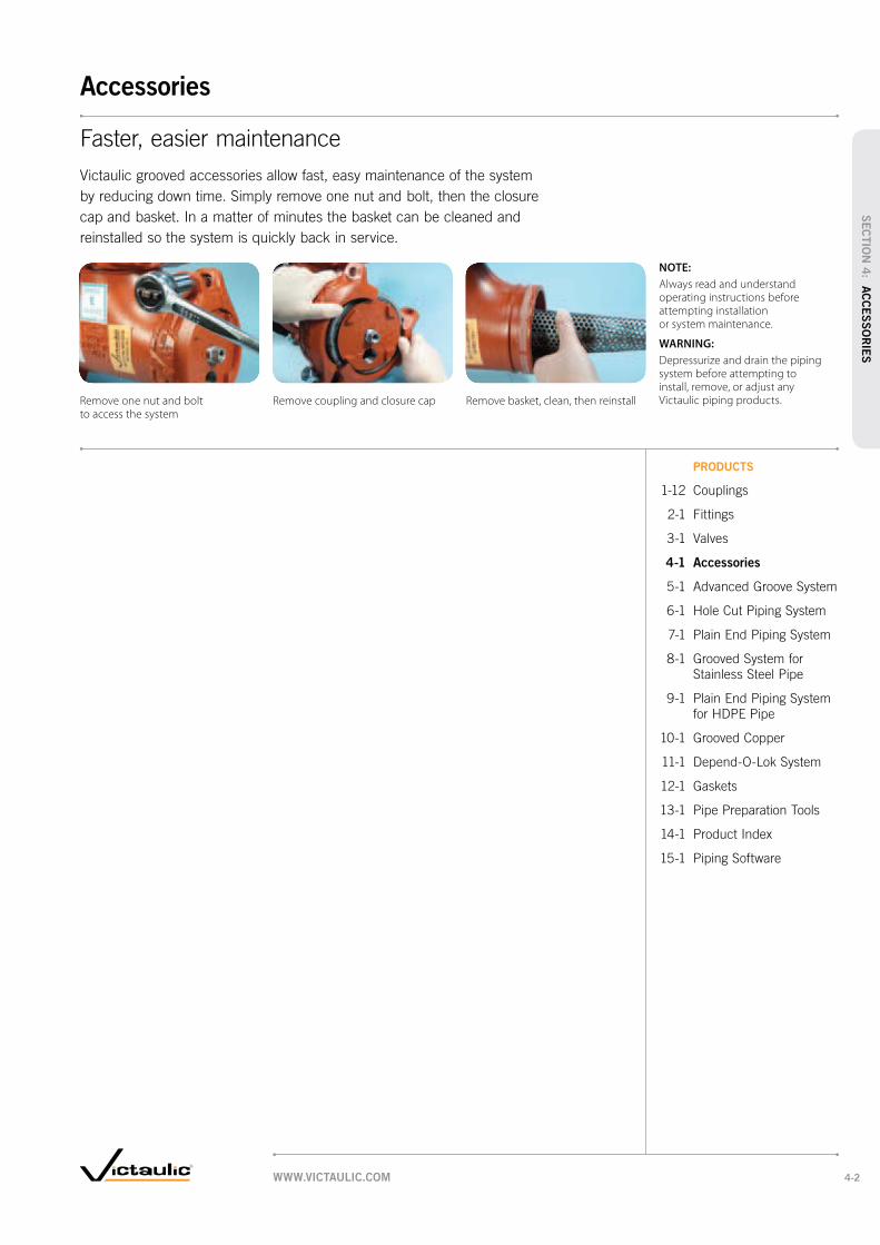
PRODUCTS
4-1 Accessories
Remove one nut and bolt to access the system
Remove coupling and closure cap Remove basket, clean, then reinstall
NOTE:
Always read and understand operating instructions before attempting installation or system maintenance.
WARNING:
Depressurize and drain the piping system before attempting to install, remove, or adjust any Victaulic piping products.
WWW.VICTAULIC.COM 4-2
Accessories
SEC
TIO
N 4
: AC
CE
SS
OR
IES

Size DimensionsApprox.
Wgt. Each
System Side
(Inlet)
×Pump Side
(Outlet)
D mm
Inches
Nominal Size mm
Inches
C-E1 mm
Inches
C-E2 † mm
Inches
CLR mm
Inches
C-O mm
Inches
L mm
Inches
OAL mm
Inches
OAW mm
Incheskg
Lbs.
76.1 mm ×60.3
—173 305 173 26 84 311 171 13.6
2 6.81 12.0 6.81 1.01 3.32 12.25 6.75 30.0
88.9×
60.3 108—
305 173 26 84 311 171 9.13 2 4.25 12.0 6.81 1.01 3.31 12.25 6.75 20.0
76.1 mm108
—305 173 26 84 311 208 9.1
4.25 12.0 6.81 1.01 3.31 12.25 8.20 20.0
88.9—
207 356 207 34 101 368 211 24.53 8.13 14.0 8.13 1.34 3.97 14.50 8.29 54.0
114.3×
60.3—
1.68 305 173 26 84 311 171 12.24 2 7.31 12.0 6.81 1.01 3.31 12.25 6.75 27.0
73.1—
1.68 305 173 26 84 311 200 12.22 ½ 7.31 12.0 6.81 1.01 3.31 12.25 7.87 27.0
76.1 mm —1.68 305 173 26 84 311 208 12.27.31 12.0 6.81 1.01 3.31 12.25 8.20 27.0
88.9 127—
356 207 34 101 368 211 20.43 5.00 14.0 8.13 1.34 3.97 14.50 8.29 45.0
114.3—
232 406 232 48 121 406 251 34.94 9.13 16.0 9.13 1.87 4.75 16.00 9.87 77.0
139.7 mm × 76.1 mm —224 305 173 26 84 311 208 20.08.81 12.0 6.81 1.01 3.31 12.25 8.20 44.0
88.9—
245 356 207 34 101 368 211 28.13 9.63 14.0 8.13 1.34 3.97 14.50 8.29 62.0
114.3 140—
406 232 48 121 406 251 24.94 5.50 16.0 9.13 1.87 4.75 16.00 9.87 55.0
139.7 mm —270 457 257 60 133 457 274 27.2
10.63 18.0 10.13 2.36 5.25 18.00 10.78 60.0
141.3×
73.1—
211 305 173 26 84 311 200 20.05 2 ½ 8.31 12.0 6.81 1.01 3.32 12.25 7.87 44.0
88.9—
219 356 207 34 101 368 211 28.13 8.63 14.0 8.13 1.34 3.97 14.50 8.29 62.0
114.3 140—
406 232 48 121 406 251 20.44 5.50 16.0 9.13 1.87 4.75 16.00 9.87 45.0
141.3—
270 457 270 60 133 470 277 62.15 10.63 18.0 10.63 2.36 5.25 18.50 10.90 173.0
165.1 mm ×88.9
—232 356 207 34 101 368 216 39.5
3 9.13 14.0 8.13 1.34 3.97 14.50 8.5 87.0
114.3—
245 406 232 48 121 406 252 38.64 9.63 16.0 9.13 1.87 4.75 16.00 9.94 85.0
139.7 mm165
—457 270 60 133 470 274 31.8
6.5 18.0 10.63 2.36 5.25 18.50 10.78 70.0
165.1—
327 559 327 83 168 565 303 61.26 12.88 22.0 12.88 3.27 6.60 22.25 11.95 135.0
† Dimension only applies when coupling and reducer are used on the system side inlet.
IMPORTANT NOTES:
See Recommended Minimum Clearance Required to Remove Diffuser Basket on pg. 4-3.
Sizes conform to EN1092 and PN10/16 flanges.
Sizes shown are nominal DN sizes, except where actual mm sizes are shown.
C - O
CLR
OAL
L
C-E1
C-E2
D
System Side(Inlet)
Pump Side(Outlet)
Suction Diffuser
SERIES 731-I
09.01
TYPICAL FOR ALL SIZES
WWW.VICTAULIC.COM4-3
Accessories
SEC
TIO
N 4
: A
CCE
SS
OR
IES
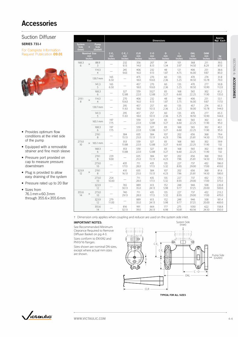
Size DimensionsApprox.
Wgt. Each
System Side
(Inlet)
×Pump Side
(Outlet)
D mm
Inches
Nominal Size mm
Inches
C-E1 mm
Inches
C-E2 † mm
Inches
CLR mm
Inches
C-O mm
Inches
L mm
Inches
OAL mm
Inches
OAW mm
Incheskg
Lbs.
168.3×
88.9—
232 356 207 34 101 368 211 39.56 3 9.13 14.0 8.13 1.34 3.97 14.50 8.29 87.0
114.3—
245 406 232 48 121 406 251 38.64 9.63 16.0 9.13 1.87 4.75 16.00 9.87 85.0
139.7 mm165
—475 270 60 133 470 274 31.8
6.50 18.0 10.63 2.36 5.25 18.50 10.78 70.0
141.3 165—
457 270 60 133 470 277 50.85 6.50 18.0 10.63 2.36 5.25 18.50 10.90 112.0
168.3—
327 559 3327 83 168 565 302 61.26 12.88 22.0 12.88 3.27 6.60 22.25 11.90 135.0
219.1×
114.3—
270 406 232 48 146 406 251 53.18 4 10.63 16.0 9.13 1.87 5.75 16.00 9.87 117.0
139.7 mm —295 457 257 60 133 457 274 65.3
11.63 18.0 10.13 2.36 5.25 18.00 10.78 144.0
141.3 — 295 457 257 60 133 470 277 65.35 11.63 18.0 10.13 2.36 5.25 18.50 10.90 144.0
165.1 mm197
—559 327 83 168 565 302 43.1
7.75 22.0 12.88 3.27 6.60 22.25 11.90 95.0
168.3 197—
559 327 83 168 565 302 43.16 7.75 22.0 12.88 3.27 6.60 22.25 11.90 95.0
219.1—
384 635 384 107 202 656 368 79.48 15.13 25.0 15.13 4.23 7.96 25.81 14.50 175.0
273.0× 165.1 mm —
353 559 327 83 168 565 302 59.910 13.88 22.0 12.88 3.27 6.60 22.25 11.90 132
168.3—
353 559 327 83 168 565 302 59.96 13.88 22.0 12.88 3.27 6.60 22.25 11.90 132
219.1 229—
635 384 107 202 656 368 59.08 9.00 25.0 15.13 4.23 7.96 25.81 14.50 130.0
273.0—
435 711 435 135 227 737 432 186.010 17.13 28.0 17.13 5.32 8.93 29.00 17.00 410.0
323.9×
219.1—
410 635 384 107 202 656 368 81.612 8 16.13 25.0 15.13 4.23 7.96 25.81 14.50 180.0
273.0 254—
711 435 135 227 737 432 170.110 10.00 28.0 17.13 5.32 8.93 29.00 17.00 375.0
323.9—
765 889 613 152 248 946 508 226.812 30.13 35.0 24.13 5.98 9.77 37.25 20.00 500.0
355.6×
273.0—
740 711 435 135 227 737 432 213.214 10 29.13 28.0 17.13 5.32 8.93 29.00 17.00 470.0
323.9 279—
889 613 152 248 946 508 181.412 11.00 35.0 24.13 5.98 9.77 37.25 20.00 400.0
355.6—
816 991 664 177 275 1030 622 158.814 32.13 39.0 26.13 6.98 10.81 40.56 24.50 350.0
† Dimension only applies when coupling and reducer are used on the system side inlet.
IMPORTANT NOTES:
See Recommended Minimum Clearance Required to Remove Diffuser Basket on pg. 4-3.
Sizes conform to EN1092 and PN10/16 flanges.
Sizes shown are nominal DN sizes, except where actual mm sizes are shown.
C - O
CLR
OAL
L
C-E1
C-E2
D
System Side(Inlet)
Pump Side(Outlet)
Suction Diffuser
SERIES 731-I
09.01
TYPICAL FOR ALL SIZES
WWW.VICTAULIC.COM 4-4
Accessories
SEC
TIO
N 4
: AC
CE
SS
OR
IES

SizeMax. Work Pressure † Dimensions
Approx. Wgt. Each
Flow Coefficient@ (Fully Open)
KV Values
C V Values
Nominal Size mm
Inches
Actual Outside
Diameter mm
IncheskPa psi
A mm
Inches
B mm
Inches
X mm
Inches
Y mm
Inches
H mm
Inches
kg
Lbs.
40 48.3 5175 140 95 75 148 6 3.2 52.81 1/2 1.900 750 5.50 3.75 2.94 5.81 0.25 7.0 61
50 60.3 5175 165 108 85 147 13 2.6 164.42 2.375 750 6.50 4.25 3.35 5.78 0.50 5.8 190
65 73.0 5175 191 121 98 162 13 4.0 199.02 1/2 2.875 750 7.50 4.75 3.88 6.38 0.50 8.9 230
80 88.9 5175 216 133 115 173 19 9.5 250.93 3.500 750 8.50 5.25 4.54 6.81 0.75 21.0 290
100 114.3 5175 254 152 148 209 25 8.9 367.64 4.500 750 10.00 6.00 5.83 8.21 1.00 19.6 425
125 141.3 5175 279 165 179 251 32 14.2 592.55 5.563 750 11.00 6.50 7.03 9.89 1.25 31.3 685
150 168.3 4825 330 191 210 275 32 19.6 821.86 6.625 700 13.00 7.50 8.26 10.83 1.25 43.3 950
200 219.1 4130 394 229 268 349 51 34.0 1823.48 8.625 600 15.50 9.00 10.54 13.74 2.00 75.0 2108
250 273.0 3450 457 260 327 431 51 61.7 2320.810 10.750 500 18.00 10.25 12.86 16.98 2.00 136.0 2683
300 323.9 2750 508 286 377 480 51 89.4 3349.312 12.750 400 20.00 11.25 14.86 18.88 2.00 197.2 3872
350 – 600 14 – 24
See AGS Series W730, pg. 5-14
† Working pressure is maximum based on Style 07 access coupling and will be governed by couplings used for installation and related system components. Maximum differential pressure from inlet to outlet must not exceed 69 kPa/10 psi.
@ KV/C
V values for flow of water at +16°C/60°F.
IMPORTANT NOTES:
For 500 – 750 mm/20 – 30" sizes contact Victaulic.
Sizes shown are nominal DN sizes, except where actual mm sizes are shown.
A
B
X
Y
PIPE PLUG, "H" N.P.T.
SERIES 730
09.02
TYPICAL FOR ALL SIZES
WWW.VICTAULIC.COM4-5
Accessories
SEC
TIO
N 4
: A
CCE
SS
OR
IES
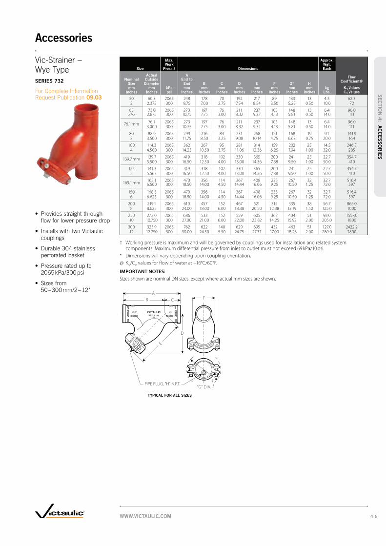
Size
Max. Work
Press.† Dimensions
Approx. Wgt. Each
Flow Coefficient@
KV Values
C V Values
Nominal Size mm
Inches
Actual Outside
Diameter mm
IncheskPa psi
A End to End mm
Inches
B mm
Inches
C mm
Inches
D mm
Inches
E mm
Inches
F mm
Inches
G* mm
Inches
H mm
Inches
kg
Lbs.
50 60.3 2065 248 178 70 192 217 89 133 13 4.5 62.32 2.375 300 9.75 7.00 2.75 7.54 8.54 3.50 5.25 0.50 10.0 72
65 73.0 2065 273 197 76 211 237 105 148 13 6.4 96.02 1/2 2.875 300 10.75 7.75 3.00 8.32 9.32 4.13 5.81 0.50 14.0 111
76.1 mm 76.1 2065 273 197 76 211 237 105 148 13 6.4 96.03.000 300 10.75 7.75 3.00 8.32 9.32 4.13 5.81 0.50 14.0 111
80 88.9 2065 299 216 83 231 258 121 168 19 9.1 141.93 3.500 300 11.75 8.50 3.25 9.08 10.14 4.75 6.63 0.75 20.0 164
100 114.3 2065 362 267 95 281 314 159 202 25 14.5 246.54 4.500 300 14.25 10.50 3.75 11.06 12.36 6.25 7.94 1.00 32.0 285
139.7 mm 139.7 2065 419 318 102 330 365 200 241 25 22.7 354.75.500 300 16.50 12.50 4.00 13.00 14.36 7.88 9.50 1.00 50.0 410
125 141.3 2065 419 318 102 330 365 200 241 25 22.7 354.75 5.563 300 16.50 12.50 4.00 13.00 14.36 7.88 9.50 1.00 50.0 410
165.1 mm165.1 2065 470 356 114 367 408 235 267 32 32.7 516.46.500 300 18.50 14.00 4.50 14.44 16.06 9.25 10.50 1.25 72.0 597
150 168.3 2065 470 356 114 367 408 235 267 32 32.7 516.46 6.625 300 18.50 14.00 4.50 14.44 16.06 9.25 10.50 1.25 72.0 597
200 219.1 2065 610 457 152 467 521 315 335 38 56.7 865.08 8.625 300 24.00 18.00 6.00 18.38 20.50 12.38 13.19 1.50 125.0 1000
250 273.0 2065 686 533 152 559 605 362 404 51 93.0 1557.010 10.750 300 27.00 21.00 6.00 22.00 23.82 14.25 15.92 2.00 205.0 1800
300 323.9 2065 762 622 140 629 695 432 463 51 127.0 2422.212 12.750 300 30.00 24.50 5.50 24.75 27.37 17.00 18.23 2.00 280.0 2800
† Working pressure is maximum and will be governed by couplings used for installation and related system components. Maximum differential pressure from inlet to outlet must not exceed 69 kPa/10 psi.
* Dimensions will vary depending upon coupling orientation.
@ KV/C
V values for flow of water at +16°C/60°F.
IMPORTANT NOTES:
Sizes shown are nominal DN sizes, except where actual mm sizes are shown.
A
B
D
F
PIPE PLUG, "H" N.P.T."G" DIA.
E
C
SERIES 732
09.03
TYPICAL FOR ALL SIZES
WWW.VICTAULIC.COM 4-6
Accessories
SEC
TIO
N 4
: AC
CE
SS
OR
IES
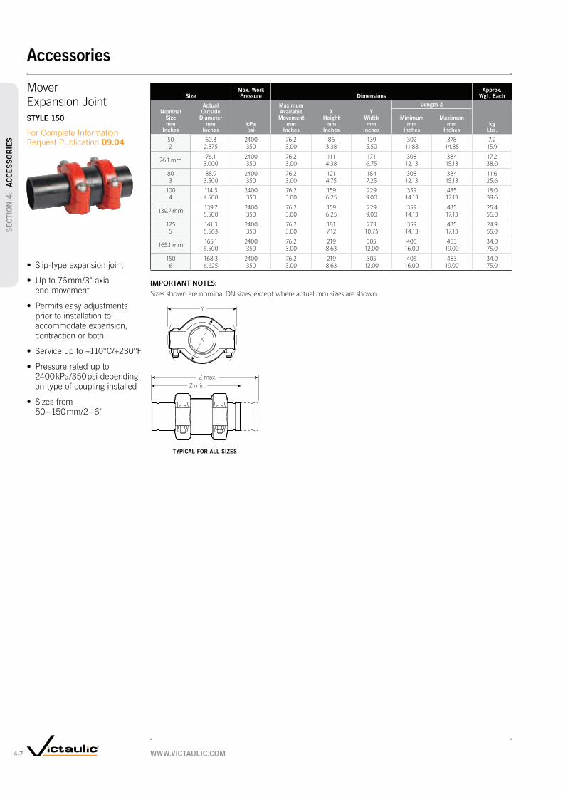
SizeMax. Work Pressure Dimensions
Approx. Wgt. Each
Actual Outside
Diameter mm
IncheskPa psi
Maximum Available Movement
mm Inches
X Height
mm Inches
Y Width mm
Inches
Length Z
Nominal Size mm
Inches
Minimum
mm Inches
Maximum mm
Incheskg
Lbs.
50 60.3 2400 76.2 86 139 302 378 7.22 2.375 350 3.00 3.38 5.50 11.88 14.88 15.9
76.1 mm76.1 2400 76.2 111 171 308 384 17.2
3.000 350 3.00 4.38 6.75 12.13 15.13 38.0
80 88.9 2400 76.2 121 184 308 384 11.63 3.500 350 3.00 4.75 7.25 12.13 15.13 25.6
100 114.3 2400 76.2 159 229 359 435 18.04 4.500 350 3.00 6.25 9.00 14.13 17.13 39.6
139.7 mm139.7 2400 76.2 159 229 359 435 25.45.500 350 3.00 6.25 9.00 14.13 17.13 56.0
125 141.3 2400 76.2 181 273 359 435 24.95 5.563 350 3.00 7.12 10.75 14.13 17.13 55.0
165.1 mm165.1 2400 76.2 219 305 406 483 34.06.500 350 3.00 8.63 12.00 16.00 19.00 75.0
150 168.3 2400 76.2 219 305 406 483 34.06 6.625 350 3.00 8.63 12.00 16.00 19.00 75.0
IMPORTANT NOTES:
Sizes shown are nominal DN sizes, except where actual mm sizes are shown.
X
Y
Z min.
Z max.
STYLE 150
09.04
TYPICAL FOR ALL SIZES
WWW.VICTAULIC.COM4-7
Accessories
SEC
TIO
N 4
: A
CCE
SS
OR
IES

Size Dimensions Approx.
Wgt. Each
Actual Outside
Diameter mm
L Length
mm Movement
mm
Spring Constant
mm W.T./T
mm Bellows/D1
mm
Nominal Size mm kg
200 DN 219.1 390 +/- 50 171 8.18 255 10.02
250 DN 273.0 435 +/- 50 205 9.27 315 17.58
300 DN 323.9 435 +/- 50 179 9.52 380 22.20
IMPORTANT NOTES:
For Performance Data refer to 06.02 for Style 07.
Sizes shown are nominal DN sizes, except where actual mm sizes are shown.
STYLE 151
09.06
WWW.VICTAULIC.COM 4-8
Accessories
SEC
TIO
N 4
: AC
CE
SS
OR
IES

Standard Units †
Size Style DimensionsApprox.
Wgt. Each
Actual Outside
Diameter mm
InchesCoupling
Style
L - Length (ref.) §
X Height
mm Inches
Y Width mm
Inches
Total Movement Capability
mm Inches
kg Lbs.
Nominal Size mm
Inches
Compressed mm
Inches
Expanded mm
Inches
20 26.7 77 667 715 54 92 48 7.73/4 1.050 26.25 28.13 2.13 3.63 1.88 17.0
25 33.7 77 667 715 61 99 48 9.11 1.315 26.25 28.13 2.38 3.88 1.88 20.0
32 42.4 77 718 765 67 118 48 12.71 1/4 1.660 28.25 30.13 2.63 4.63 1.88 28.0
40 48.3 77 718 765 76 127 48 14.11 1/2 1.900 28.25 30.13 3.00 5.00 1.88 31.0
50 60.3 75 718 765 89 130 48 12.22 2.375 28.25 30.13 3.50 5.13 1.88 27.0
65 73.0 75 718 765 102 149 48 16.32 1/2 2.875 28.25 30.13 4.00 5.88 1.88 36.0
76.1 mm 76.1 75 718 765 102 149 48 16.33.000 28.25 30.13 4.00 5.88 1.88 36.0
80 88.9 75 718 765 118 172 48 20.93 3.500 28.25 30.13 4.63 6.75 1.88 46.0
90 101.6 75 718 765 133 188 48 24.53 1/2 4.000 28.25 30.13 5.25 7.38 1.88 54.0
100 114.3 75 667 711 149 203 45 24.54 4.500 26.25 28.00 5.88 8.00 1.75 54.0
139.7 mm 139.7 75 667 711 178 259 45 32.75.500 26.25 28.00 7.00 10.18 1.75 72.0
125 141.3 75 667 711 178 259 45 32.75 5.563 26.25 28.00 7.00 10.18 1.75 72.0
165.1 mm 165.1 75 667 711 207 279 45 40.86.500 26.25 28.00 8.13 11.00 1.75 90.0
150 168.375
667 711 207 279 45 40.86 6.625 26.25 28.00 8.13 11.00 1.75 90.0
200 219.1 75 724 768 264 356 45 68.08 8.625 28.50 30.25 10.38 14.00 1.75 150.0
250 273.0 77 826 870 343 426 45 145.210 10.750 32.50 34.25 13.50 16.75 1.75 320.0
300 323.9 77 826 870 394 483 45 169.212 12.750 32.50 34.25 15.50 19.00 1.75 373.0
† Contact Victaulic for performance requirements not listed above.
§ Dimensions may vary slightly due to tolerances.
IMPORTANT NOTES:
For Performance Data refer to 06.05 for Style 75 and 06.04 for Style 77.
350 – 600 mm/14 – 24" sizes available in the Advanced Grooved System. Contact Victaulic for details.
Sizes shown are nominal DN sizes, except where actual mm sizes are shown.
L
Y
X
L
Y
X
STYLE 155
09.05
TYPICAL 20 – 90 mm/¾ – 3½" SIZES TYPICAL 100 – 300 mm/4 – 12" SIZES
WWW.VICTAULIC.COM4-9
Accessories
SEC
TIO
N 4
: A
CCE
SS
OR
IES

SizeMaximum Working
Pressure DimensionsApprox.
Weight Each
Actual Outside Diameter
Nominal Size mm
Inches
Steel mm
Inches
Copper mm
IncheskPa psi
End to End mm
Incheskg
Lbs.
50 60.3 54.0 2065 106 0.62 2.375 2.125 300 4.19 1.3
65 73.0 66.7 2065 157 1.52 1/2 2.875 2.625 300 6.19 3.3
80 88.9 79.4 2065 157 2.03 3.500 3.125 300 6.19 4.5
100 114.3 104.8 2065 157 2.64 4.500 4.125 300 6.19 5.8
125 141.3 130.2 2065 157 3.55 5.563 5.125 300 6.19 7.8
150 168.3 155.6 2065 157 4.66 6.625 6.125 300 6.19 10.1
200 219.1 206.4 2065 157 6.88 8.625 8.125 300 6.19 15.0
IMPORTANT NOTES:
Sizes shown are nominal DN sizes, except where actual mm sizes are shown.
Size Style 47-GT Grooved × Threaded Style 47-TT Threaded × Threaded
Nominal Size mm
Inches
Actual Outside Dia.
mm Inches
Max. Working Pressure
kPa psi
End to End mm
Inches
Approx. Wgt. Each
kg Lbs.
Max. Working Pressure
kPa psi
End to End mm
Inches
Approx. Wgt. Each
kg Lbs.
15 21.3 — — — 2065 76 0.11/2 0.840 300 3.00 0.2
20 26.7— — —
2065 76 0.13/4 1.050 300 3.00 0.2
25 33.7 2065 102 0.2 2065 102 0.21 1.315 300 4.00 0.3 300 4.00 0.3
32 42.4 2065 102 0.3 2065 102 0.31 1/4 1.660 300 4.00 0.6 300 4.00 0.6
40 48.3 2065 102 0.3 2065 102 0.31 1/2 1.900 300 4.00 0.8 300 4.00 0.8
50 60.3 2065 102 0.5 2065 102 0.52 2.375 300 4.00 1.0 300 4.00 1.0
65 73.0 2065 152 0.7 2065 152 0.72 1/2 2.875 300 6.00 1.6 300 6.00 1.6
80 88.9 2065 152 0.9 2065 152 0.93 3.500 300 6.00 2.0 300 6.00 2.0
90 101.6 2065 152 1.1 2065 152 1.13 1/2 4.000 300 6.00 2.3 300 6.00 2.3
100 114.3 2065 152 2.0 2065 152 2.04 4.500 300 6.00 4.5 300 6.00 4.5
@ Available with British Standard Pipe Threads, specify “BSP” clearly on order.
IMPORTANT NOTES:
Sizes shown are nominal DN sizes, except where actual mm sizes are shown.
E to E
E to E E to E
STYLE 47-GG GRV. × GRV. GROOVED END STEEL TO GROOVED COPPER TRANSITION
STYLE 47
09.07
* ClearFlow is a registered trademark of Perfection Corp.
STYLE 47-GT @ GRV. × THD.
STYLE 47-TT @ THD. × THD.
WWW.VICTAULIC.COM 4-10
Accessories
SEC
TIO
N 4
: AC
CE
SS
OR
IES

Victaulic offers a full range of 350 – 600 mm/14 – 24" Advanced Groove System
(AGS) couplings, fittings, valves and accessories – making AGS a comprehensive
solution for large diameter piping. Because the AGS coupling system provides
great strength and dependability in addition to speed, it’s an excellent choice over
welding. Other advantages AGS joints provide over welded joints include no flame,
superior seismic-shock resistance and a union at every joint for easy adjustment,
system maintenance or system expansion.
Rigid CouplingSTYLE W07, PG. 5-3
Vic-300 AGS
Butterfly ValveVIC-300, PG. 5-11
Flexible CouplingSTYLE W77, PG. 5-3
Dual Disc
Vic-Check ValveSERIES W715, PG. 5-10
Vic-Strainer –
Tee TypeSERIES W730, PG. 5-13
Couplings
Valves Accessories
Rigid Coupling for
Stainless Steel PipeSTYLE W89, PG. 5-4
Vic-Fange Adapter
for AGSSTYLE W741, PG. 5-4
WWW.VICTAULIC.COM5-1
Advanced Groove System
SEC
TIO
N 5
: A
DVA
NCED
GR
OO
VE
SYSTEM

VICTAULIC
No.W11
VICTAULIC
No.W10
VICTAULIC
No.W20
VICTAULIC
No.W11
VICTAULIC
No.W10
VICTAULIC
No.W35
VICTAULIC
No.W30
VICTAULIC
No.W25
VICTAULIC
No.W33
VICTAULIC
No.W30-R
VICTAULIC
No.W50
VICTAULIC
No.W51
VICTAULIC
No.W60
PRODUCTS
1-12 Couplings
2-1 Fittings
3-1 Valves
4-1 Accessories
5-1 Advanced Groove System
6-1 Hole Cut Piping System
7-1 Plain End Piping System
8-1 Grooved System for
Stainless Steel Pipe
9-1 Plain End Piping System
for HDPE Pipe
10-1 Grooved Copper
11-1 Depend-O-Lok System
12-1 Gaskets
13-1 Pipe Preparation Tools
14-1 Product Index
15-1 Piping Software
Wider gasket delivers more contact area for superior sealing
Deeper, wider wedge shape groove for strong,
dependable joints
Wider housing profile for greater end load capability
A complete piping system, for sizes 350 – 600 mm/14 – 24"
Fittings
* Original Victaulic groove (not compatible with AGS couplings)
90° Elbow
NO. W10, PG. 5-5
45° Elbow
NO. W11, PG. 5-5
22½° Elbow
NO. W12, PG. 5-5
90° 1½ D Long Radius Elbow
NO. W100, PG. 5-5
45° 1½ D Long Radius Elbow
NO. W110, PG. 5-5
True Wye
NO. W33, PG. 5-5
Reducing Tee
NO. W25, PG. 5-6
Tee
NO. W20, PG. 5-5
45º Lateral
NO. W30, PG. 5-7
45° Reducing Lateral
NO. W30-R, PG. 5-7
Adapter Nipple AGS Grv. × Bev.
NO. W42, PG. 5-8
Adapter Nipple AGS Grv. × AGS Grv.
NO. W43, PG. 5-8
Adapter Nipple AGS Grv. × Original Grv. *
NO. W49, PG. 5-8
Flanged Adapter Nipple
NO. W45R, PG. 5-8
Concentric Reducer
NO. W50, PG. 5-9
Cap
NO. W60, PG. 5-8
Eccentric Reducer
NO. W51, PG. 5-9
11¼º Elbow
NO. W13, PG. 5-5
Cross
NO. W35, PG. 5-5
WWW.VICTAULIC.COM 5-2
Advanced Groove System
SEC
TIO
N 5
: AD
VA
NCED
GR
OO
VE
SYSTEM

SizeMax. Work Pressure*
Max. End Load*
Allow. Pipe End Sep.‡ Dimensions
Approx. Wgt. Each
Nominal Size mm
Inches
Actual Outside Dia.
mm Inches
Std. Wall kPa psi
Light Wall† kPa psi
Std. Wall N
Lbs.
Light Wall†
N Lbs.
mm Inches
X mm
Inches
Y mm
Inches
Z mm
Incheskg
Lbs.
350 355.6 2500 2500 248310 248310 6.4 403 523 121 22.214 14.000 350 § 350 § 55800 55800 0.25 15.87 20.59 4.75 48.9
400 406.4 2500 2500 324338 324338 6.4 460 597 121 27.616 16.000 350 § 350 § 72885 72885 0.25 18.12 23.51 4.75 60.8
450 457.0 2500 2500 410490 410490 6.4 514 648 121 32.318 18.000 350 § 350 § 92245 92245 0.25 20.22 25.53 4.75 71.2
500 508.0 2500 2500 506766 506766 6.4 570 389 121 37.120 20.000 350 § 350 § 113880 113880 0.25 22.44 27.13 4.75 81.7
600 610.0 2500 1600 729756 467050 6.4 677 821 121 52.724 24.000 350 § 225 § 163990 104955 0.25 26.64 32.31 4.75 116.2
* Working Pressure and End Load are total, from all internal and external loads, based on standard weight (ANSI) steel pipe, AGS roll grooved in accordance with Victaulic specifications. Contact Victaulic for performance on other pipe.
WARNING: FOR ONE TIME FIELD TEST ONLY, the Maximum Joint Working Pressure may be increased to 1 ½ times the figures shown.
† Light wall 350 mm/14" = 5.6 mm/0.22"; 400 – 600 mm/ 16 – 24" = 0.25"/6.35 mm
‡ For field installation only on roll grooved pipe. Style W07 AGS couplings are essentially rigid and do not permit expansion/contraction.
§ Pressure ratings have been rounded for global use. Actual maximum working pressure for light wall in 350 – 500 mm/14 – 20" sizes is 2500 kPa/363 psi; 600 mm/24" is 1600 kPa/232 psi and standard wall in 350 – 600 mm/14 – 24" is 2500 kPa/363 psi.
IMPORTANT NOTES:
Style W07 AGS couplings must not be used to join PVC pipe.
Sizes shown are nominal DN sizes, except where actual mm sizes are shown.
SizeMax. Work Pressure*
Max. End Load*
Allow. Pipe End Sep.‡ Dimensions
Approx. Wgt. Each
Nominal Size mm
Inches
Actual Outside Dia.
mm Inches
Std. Wall kPa psi
Light Wall† kPa psi
Std. Wall N
Lbs.
Light Wall†
N Lbs.
mm Inches
X mm
Inches
Y mm
Inches
Z mm
Incheskg
Lbs.
350 355.6 2500 2500 248310 248310 3.1 – 7.9 406 523 114 21.514 14.000 350 § 350 § 55800 55800 0.13 – 0.31 16.00 20.59 4.50 47.5
400 406.4 2500 2500 324338 324338 3.1 – 7.9 462 597 114 26.216 16.000 350 § 350 § 72885 72885 0.13 – 0.31 18.18 23.51 4.50 57.8
450 457.2 2500 2500 410490 410490 3.1 – 7.9 517 647 114 29.518 18.000 350 § 350 § 92245 92245 0.13 – 0.31 20.36 25.46 4.50 65.0
500 508.0 2500 2500 506766 506766 3.1 – 7.9 573 689 114 37.320 20.000 350 § 350 § 113880 113880 0.13 – 0.31 22.56 27.13 4.50 82.3
600 610.0 2500 1600 729756 467050 3.1 – 7.9 683 821 114 48.424 24.000 350 § 225 § 163990 104955 0.13 – 0.31 26.88 32.31 4.50 106.8
* Working Pressure and End Load are total, from all internal and external loads, based on standard weight (ANSI) steel pipe, AGS roll grooved in accordance with Victaulic specifications. Contact Victaulic for performance on other pipe.
WARNING: FOR ONE TIME FIELD TEST ONLY, the Maximum Joint Working Pressure may be increased to 1 ½ times the figures shown.
† Light wall 350 mm/14" = 5.6 mm/0.22"; 400 – 600 mm/ 16 – 24" = 0.25"/6.35 mm
‡ Allowable Pipe End Separation figures show the maximum nominal range of movement available at each joint for AGS roll grooved pipe. These figures are maximums; for design and installation purposes these figures should be reduced by 25%. Refer to General Notes on pg. 1-15.
§ Pressure ratings have been rounded for global use. Actual maximum working pressure for lightwall in 350 – 500 mm/14 – 20" sizes is 2500 kPa/363 psi; 600 mm/24" is 1600 kPa/232 psi and standard wall in 350 – 600 mm/14 – 24" is 2500 kPa/363 psi.
IMPORTANT NOTES:
Style W77 AGS couplings must not be used to join PVC pipe.
Sizes shown are nominal DN sizes, except where actual mm sizes are shown.
Y Z
X
Y Z
X
Rigid Coupling
STYLE W07
For Complete Information Request Publication 20.02
Flexible Coupling
STYLE W77
For Complete Information Request Publication 20.03
two-piece, flat pad,
metal-to-metal rigid
coupling in this size range
requirements correspond to
ASME B31.1 Power Piping
code and ASME B31.9
Building Services code
2400 kPa/350 psi
flexible two-piece housing
for this size range on the
market today
linear angular movement to
accommodate thermal pipe
growth, vibration attenuation,
seismic and other design
considerations that
require flexibility
2400 kPa/350 psi
TYPICAL FOR ALL SIZES
TYPICAL FOR ALL SIZES
WWW.VICTAULIC.COM5-3
SEC
TIO
N 5
: A
DVA
NCED
GR
OO
VE
SYSTEM
Advanced Groove System – Couplings

SizeMax. Work Pressure*
Max. End Load*
Sealing Surface Dimensions
Approx. Wgt. Each
Nominal Size mm
Inches
Actual Outside Dia.
mm Inches
Std. Wall kPa psi
Light Wall† kPa psi
Std. Wall N
Lbs.
Light Wall†
N Lbs.
A Max. mm
Inches
B Min. mm
Inches
W mm
Inches
Z mm
Incheskg
Lbs.
350 355.6 2065 2065 205501 205501 356 406 622 60 30.014 14.000 300 300 46180 46180 14.00 16.00 24.5 2.38 66.0
400 406.4 2065 2065 268402 268402 406 457 688 60 37.016 16.000 300 300 60315 60315 16.00 18.00 27.1 2.38 81.0
450 457.2 2065 2065 339713 339713 457 508 737 65 38.018 18.000 300 300 76340 76340 18.00 20.00 29.0 2.56 84.0
500 508.0 2065 2065 419413 419413 508 559 800 68 50.020 20.000 300 300 94250 94250 20.00 22.00 31.5 2.69 110.0
600 610.0 2065 1600 603932 452943 610 660 914 70 70.024 24.000 300 225# 135715 101785 24.00 26.00 36.0 2.74 155.0
* Working Pressure and End Load are total, from all internal and external loads, based on carbon steel pipe AGS roll grooved in accordance with Victaulic specifications. Contact Victaulic for performance on other pipe.
WARNING: FOR ONE TIME FIELD TEST ONLY, the Maximum Joint Working Pressure may be increased to 1 ½ times the figures shown.
† Lightwall 350 mm/14" = 5.6 mm/0.22"; 400 – 600 mm/ 16 – 24" = 0.25"/6.35 mm
# Rounded for global use. Actual maximum working pressure is 1600 kPa/232 psi.
IMPORTANT NOTES:
Style W741 AGS Vic-Flange adapter provides rigid joints when used on pipe with AGS groove dimensions and consequently allows no linear or angular movement at the joint.
Sizes shown are nominal DN sizes, except where actual mm sizes are shown.
SizeMax. Work Pressure*
Max. End Load*
Allow. Pipe End Sep.† Dimensions
Approx. Wgt. Each
Nominal Size mm
Inches
Actual Outside Dia.
mm Inches
kPa psi
N Lbs.
mm Inches
X mm
Inches
Y mm
Inches
Z mm
Incheskg
Lbs.
350 355.6 2065 205590 6.4 419 543 122 29.514 14.000 300 46200 0.25 16.50 21.38 4.81 65.0
400 406.4 2065 268424 6.4 480 597 122 36.416 16.000 300 60320 0.25 18.88 23.50 4.81 80.0
450 457.0 2065 339758 6.4 533 651 122 42.318 18.000 300 76350 0.25 21.00 25.63 4.81 93.0
500 508.0 2065 419413 6.4 603 702 122 51.820 20.000 300 94250 0.25 23.75 27.63 4.81 114.0
600 610.0 2065 603865 6.4 762 813 122 82.624 24.000 300 135700 0.25 30.00 32.00 4.81 182.0
* Working Pressure and End Load are total, from all internal and external loads, based on stainless steel pipe, AGS roll grooved in accordance with Victaulic specifications. “RWX” rolls must be used for Schedule 10S. Contact Victaulic for performance on other pipe.
WARNING: FOR ONE TIME FIELD TEST ONLY, the Maximum Joint Working Pressure may be increased to 1 ½ times the figures shown.
† For field installation only on roll grooved pipe. Style W89 AGS couplings are essentially rigid and do not permit expansion/contraction.
IMPORTANT NOTES:
Sizes shown are nominal DN sizes, except where actual mm sizes are shown.
ZW
A B
Y Z
X
Vic-Flange Adapter
for AGS
STYLE W741
For Complete Information Request Publication 20.04
incorporating flanged
components with ANSI
Class 125/150 bolt hole
patterns into an AGS
grooved pipe system
2065 kPa/300 psi
TYPICAL FOR ALL SIZES
Rigid Coupling for
Stainless Steel Pipe
STYLE W89
For Complete Information Request Publication 20.15
stainless steel systems
essentially rigid joint
2065 kPa/300 psi TYPICAL FOR ALL SIZES
WWW.VICTAULIC.COM 5-4
SEC
TIO
N 5
: AD
VA
NCED
GR
OO
VE
SYSTEM
Advanced Groove System – Couplings

SizeNo. W10
90º ElbowNo. W11
45º ElbowNo. W12
22½° Elbow (sw)No. W13
11¼° Elbow (sw)No. W100
90° Long Radius Elbow (S)No. W110
45° Long Radius Elbow (S)
Nominal Size mm
Inches
Actual Outside Dia.
mm Inches
C to E mm
Inches
Approx. Wgt. Each
kg Lbs.
C to E mm
Inches
Approx. Wgt. Each
kg Lbs.
C to E mm
Inches
Approx. Wgt. Each
kg Lbs.
C to E mm
Inches
Approx. Wgt. Each
kg Lbs.
C to E mm
Inches
Approx. Wgt. Each
kg Lbs.
C to E mm
Inches
Approx. Wgt. Each
kg Lbs.
350 355.6 355.6 68.4 147 28.7 127 20.9 89 14.5 533 71.7 222 37.614 14.000 14.00 150.8 5.80 63.0 5.00 46.0 3.50 32.0 21.00 158.0 8.75 83.0
400 406.4 406.4 83.6 168 42.5 127 23.6 102 19.1 610 92.7 254 45.816 16.000 16.00 184.3 6.63 93.8 5.00 52.1 4.00 42.0 24.00 204.3 10.00 101.1
450 457.0 457.0 123.5 189 58.5 140 29.5 114 24.1 686 118.0 286 57.618 18.000 18.00 272.3 7.46 129.0 5.50 65.0 4.50 53.2 27.00 260.0 11.25 127.0
500 508.0 508.0 141.5 210 75.0 152 36.0 127 29.5 762 149.0 318 75.720 20.000 20.00 312.0 8.28 165.3 6.00 78.6 5.00 65.0 30.00 328.5 12.50 167.0
600 610.0 610.0 253.9 252 120.0 178 50.0 152 42.9 914 222.3 381 110.124 24.000 24.00 559.8 9.94 264.5 7.00 110.3 6.00 94.5 36.00 490.0 15.00 244.8
# Ductile iron except those marked (sw) which are segmentally welded steel or (S) which are steel.
IMPORTANT NOTES:
Sizes shown are nominal DN sizes, except where actual mm sizes are shown.
SizeNo. W20 Tee (sw)
No. W35 Cross (sw)
No. W33 True Wye (sw)
Nominal Size mm
Inches
Actual Outside Diameter
mm Inches
C to E mm
Inches
Approx. Weight Each
kg Lbs.
C to E mm
Inches
Approx. Weight Each
kg Lbs.
C to LE mm
Inches
C to SE mm
Inches
Approx. Weight Each
kg Lbs.
350 355.6 279 75.5 279 54.9 279 191 44.414 14.000 11.00 166.5 11.00 121.0 11.00 7.50 98.0
400 406.4 305 95.5 305 66.4 305 203 54.116 16.000 12.00 210.5 12.00 146.4 12.00 8.00 119.3
450 457.0 343 127.5 343 84.1 343 216 67.318 18.000 13.50 281.0 13.50 185.4 13.50 8.50 148.3
500 508.0 381 158.7 381 103.9 381 229 81.820 20.000 15.00 350.0 15.00 229.1 15.00 9.00 180.4
600 610.0 432 228.5 432 135.5 432 254 108.124 24.000 17.00 503.7 17.00 298.7 17.00 10.00 238.3
IMPORTANT NOTES:
Sizes shown are nominal DN sizes, except where actual mm sizes are shown.
C to E
C to E
VICTAULIC
No.W100
C
to E
C to E
VICTAULIC
No.W110
C toE
VICTAULIC
No.W35
C to E
VICTAULIC
No.W33
C to
LE
C to
SE
VICTAULIC
No.W10
C
to E
C to E
VICTAULIC
No.W11
C toE
VICTAULIC
No.W20
C to E
C to E
NO. W10 NO. W11 NO. W12 NO. W13 NO. W100 NO. W110
Elbows
NO. W10 90º Elbow
NO. W11 45º Elbow
NO. W12 22½º Elbow
NO. W13 11¼º Elbow
NO. W100 90º Long Radius
NO. W110 45º Long Radius
(Ductile Iron#)
Request Publication 20.05
NO. W20 NO. W35 NO. W33
Tees, Crosses and Wyes
NO. W20 Tee
NO. W35 Cross
NO. W33 True Wye
(Segmentally Welded Steel)
For Complete Information Request Publication 20.05
WWW.VICTAULIC.COM5-5
SEC
TIO
N 5
: A
DVA
NCED
GR
OO
VE
SYSTEM
Advanced Groove System – Fittings

SizeNo. W25
Reducing TeeApprox.
Weight Each
Nominal Size mm
Inches
C to LE mm
Inches
C to SE mm
Incheskg
Lbs.
350 × 350 × 150 279 238 46.014 14 6 11.00 9.38 101.4
200 279 248 46.58 11.00 9.75 102.5
250 279 257 47.710 11.00 10.12 105.1
300 279 270 49.012 11.00 10.62 108.1
400 × 400 × 150 305 264 57.216 16 6 12.00 10.38 126.2
200 305 273 57.88 12.00 10.75 127.4
250 305 282 58.910 12.00 11.12 129.8
300 305 295 60.112 12.00 11.62 132.5
350 305 305 61.114 12.00 12.00 134.6
450 × 450 × 150 343 289 72.618 18 6 13.50 11.38 160.0
200 343 298 73.08 13.50 11.75 161.0
250 343 308 74.010 13.50 12.12 163.1
300 343 321 75.112 13.50 12.62 165.6
350 343 330 76.014 13.50 13.00 167.6
400 343 330 76.316 13.50 13.00 168.2
* Cast fitting available. Contact Victaulic for details.
IMPORTANT NOTES:
Outlets 300 mm/12" and smaller will be provided with standard Victaulic roll or cut grooves, suitable for use with standard Victaulic grooved couplings in that size range.
Sizes shown are nominal DN sizes, except where actual mm sizes are shown.
SizeNo. W25
Reducing TeeApprox.
Weight Each
Nominal Size mm
Inches
C to LE mm
Inches
C to SE mm
Incheskg
Lbs.
500 × 500 × 150 381 314 89.520 20 6 15.00 12.38 197.0
200 381 324 90.08 15.00 12.75 198.5
250 381 333 90.910 15.00 13.12 200.5
300 381 346 92.012 15.00 13.62 202.9
350 381 356 92.914 * 15.00 14.00 204.7
400 381 356 93.016 * 15.00 14.00 205.0
450 381 368 94.518 15.00 14.50 208.4
600 × 600 × 150 432 365 122.024 24 6 17.00 14.38 260.9
200 432 375 123.08 17.00 14.75 270.0
250 432 384 123.210 17.00 15.12 271.7
300 432 397 124.212 17.00 15.62 273.8
350 432 406 125.014 17.00 16.00 275.4
400 432 406 125.016 17.00 16.00 275.4
450 432 419 127.118 17.00 16.50 278.1
500 432 432 128.020 17.00 17.00 282.1
VICTAULIC
No.W25
C toSE
C toLE
Reducing Tee
NO. W25
(Segmentally Welded Steel)
For Complete Information Request Publication 20.05
NO. W25
WWW.VICTAULIC.COM 5-6
SEC
TIO
N 5
: AD
VA
NCED
GR
OO
VE
SYSTEM
Advanced Groove System – Fittings

SizeNo. W30-R
Reducing Lateral
Nominal Size mm
Inches
C to LE mm
Inches
C to SE mm
Inches
Approx. Weight Each
kg Lbs.
350 × 350 × 100 673 191 79.814 14 4 26.50 7.50 175.9
150 673 191 84.36 26.50 7.50 185.9
200 673 191 88.48 26.50 7.50 195.0
250 673 191 92.710 26.50 7.50 204.4
300 673 191 96.812 26.50 7.50 213.3
400 × 400 × 150 737 203 102.716 16 6 29.00 8.00 226.4
200 737 203 107.18 29.00 8.00 236.0
250 737 203 111.610 29.00 8.00 246.0
300 737 203 115.712 29.00 8.00 255.1
350 737 203 118.414 29.00 8.00 260.9
450 × 450 × 150 813 216 214.618 18 6 32.00 8.50 274.8
200 813 216 129.48 32.00 8.50 285.3
300 813 216 138.912 32.00 8.50 306.2
350 813 216 141.714 32.00 8.50 312.4
400 813 216 146.216 32.00 8.50 322.4
500 × 500 × 300 889 229 164.320 20 12 35.00 9.00 362.1
350 889 229 167.214 35.00 9.00 368.7
400 889 229 172.116 35.00 9.00 379.4
600 × 600 × 400 1016 254 224.524 24 16 40.00 10.00 494.9
600 1016 254 254.820 40.00 10.00 517.7
IMPORTANT NOTES:
Outlets 300 mm/12" and smaller will be provided with standard Victaulic roll or cut groove, suitable for use with standard Victaulic grooved couplings in that size range.
Sizes shown are nominal DN sizes, except where actual mm sizes are shown.
SizeNo. W30
45º Lateral
Nominal Size mm
Inches
Actual Outside Diameter
mm Inches
C to LE mm
Inches
C to SE mm
Inches
Approx. Weight Each
kg Lbs.
350 355.6 673 191 99.414 14.000 26.50 7.50 219.1
400 406.4 737 203 122.716 16.000 29.00 8.00 270.5
450 457.0 813 216 150.918 18.000 32.00 8.50 332.7
500 508.0 889 229 182.020 20.000 35.00 9.00 401.3
600 610.0 1016 254 245.524 24.000 40.00 10.00 541.3
IMPORTANT NOTES:
Sizes shown are nominal DN sizes, except where actual mm sizes are shown.
VICTAULIC
No.W30
C toLE
C toSE
C to L
E
C toLE
C toSE
C to L
E
VICTAULIC
No.W30-R
45° Lateral
NO. W30
(Segmentally Welded Steel)
For Complete Information Request Publication 20.05
45º Reducing Lateral
NO. W30-R
(Segmentally Welded Steel)
For Complete Information Request Publication 20.05
NO. W30 NO. W30-R
WWW.VICTAULIC.COM5-7
SEC
TIO
N 5
: A
DVA
NCED
GR
OO
VE
SYSTEM
Advanced Groove System – Fittings

SizeNo. W60
Cap
Nominal Size mm
Inches
Actual Outside Diameter
mm Inches
T Thickness
mm Inches
Approx. Weight Each
kg Lbs.
350 355.6 165 15.114 14.000 6.50 33.2
400 406.4 178 18.716 16.000 7.00 41.2
450 457.0 203 24.818 18.000 8.00 54.6
500 508.0 229 30.620 20.000 9.00 67.5
600 610.0 267 43.524 24.000 10.50 96.0
IMPORTANT NOTES:
Sizes shown are nominal DN sizes, except where actual mm sizes are shown.
SizeNo. W42, W43, W49 Adapter Nipple (sw)
Nominal Size mm
Inches
Actual Outside Diameter
mm Inches
E to E mm
Inches
Approx. Weight Each
kg Lbs.
350 355.6 203 16.314 14.000 8.00 36.0
400 406.4 203 19.116 16.000 8.00 42.0
450 457.0 203 21.318 18.000 8.00 47.0
500 508.0 203 23.620 20.000 8.00 52.0
600 610.0 203 28.624 24.000 8.00 63.0
IMPORTANT NOTES:
Sizes shown are nominal DN sizes, except where actual mm sizes are shown.
SizeNo. W45R
Flanged Adapter Nipple
Nominal Size mm
Inches
Actual Outside Diameter
mm Inches
E to E mm
Inches
Approx. Weight Each
kg Lbs.
350 355.6 203 55.314 14.000 8.00 122.0
400 406.4 203 61.716 16.000 8.00 136.0
450 457.0 203 76.218 18.000 8.00 168.0
500 508.0 203 94.320 20.000 8.00 208.0
600 610.0 203 124.324 24.000 8.00 274.0
IMPORTANT NOTES:
Sizes shown are nominal DN sizes, except where actual mm sizes are shown.
VICTAULIC
No.W60
T
E to E E to E E to E
E to E
Adapter Nipple
NO. W42 AGS Grv. × Bev.
NO. W43 AGS Grv. × AGS Grv.
NO. W49 AGS Grv. × Original Grv.
(Steel)
Request Publication 20.05
Cap
NO. W60
(Steel)
For Complete Information Request Publication 20.05
Flanged Adapter Nipple
NO. W45R ANSI Class 150 Raised Face
(Steel)
For Complete Information Request Publication 20.05
NO. W42 NO. W43 NO. W49
NO. W60
NO. W45R
WWW.VICTAULIC.COM 5-8
SEC
TIO
N 5
: AD
VA
NCED
GR
OO
VE
SYSTEM
Advanced Groove System – Fittings
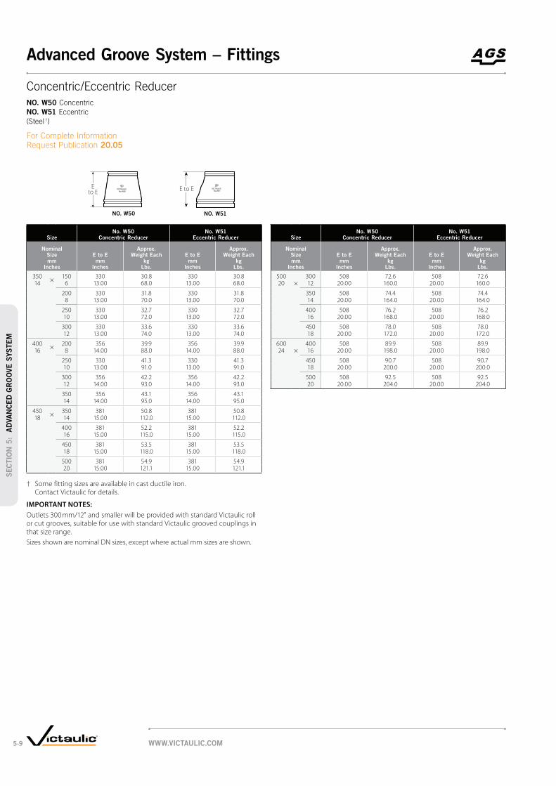
SizeNo. W50
Concentric ReducerNo. W51
Eccentric Reducer
Nominal Size mm
Inches
E to E mm
Inches
Approx. Weight Each
kg Lbs.
E to E mm
Inches
Approx. Weight Each
kg Lbs.
350×
150 330 30.8 330 30.814 6 13.00 68.0 13.00 68.0
200 330 31.8 330 31.88 13.00 70.0 13.00 70.0
250 330 32.7 330 32.710 13.00 72.0 13.00 72.0
300 330 33.6 330 33.612 13.00 74.0 13.00 74.0
400×
200 356 39.9 356 39.916 8 14.00 88.0 14.00 88.0
250 330 41.3 330 41.310 13.00 91.0 13.00 91.0
300 356 42.2 356 42.212 14.00 93.0 14.00 93.0
350 356 43.1 356 43.114 14.00 95.0 14.00 95.0
450×
350 381 50.8 381 50.818 14 15.00 112.0 15.00 112.0
400 381 52.2 381 52.216 15.00 115.0 15.00 115.0
450 381 53.5 381 53.518 15.00 118.0 15.00 118.0
500 381 54.9 381 54.920 15.00 121.1 15.00 121.1
† Some fitting sizes are available in cast ductile iron. Contact Victaulic for details.
IMPORTANT NOTES:
Outlets 300 mm/12" and smaller will be provided with standard Victaulic roll or cut grooves, suitable for use with standard Victaulic grooved couplings in that size range.
Sizes shown are nominal DN sizes, except where actual mm sizes are shown.
SizeNo. W50
Concentric ReducerNo. W51
Eccentric Reducer
Nominal Size mm
Inches
E to E mm
Inches
Approx. Weight Each
kg Lbs.
E to E mm
Inches
Approx. Weight Each
kg Lbs.
500 300 508 72.6 508 72.620 × 12 20.00 160.0 20.00 160.0
350 508 74.4 508 74.414 20.00 164.0 20.00 164.0
400 508 76.2 508 76.216 20.00 168.0 20.00 168.0
450 508 78.0 508 78.018 20.00 172.0 20.00 172.0
600 400 508 89.9 508 89.924 × 16 20.00 198.0 20.00 198.0
450 508 90.7 508 90.718 20.00 200.0 20.00 200.0
500 508 92.5 508 92.520 20.00 204.0 20.00 204.0
VICTAULIC
No.W50
Eto E
VICTAULIC
No.W51E to E
Concentric/Eccentric Reducer
NO. W50 Concentric
NO. W51 Eccentric
(Steel †)
For Complete Information Request Publication 20.05
NO. W50 NO. W51
WWW.VICTAULIC.COM5-9
SEC
TIO
N 5
: A
DVA
NCED
GR
OO
VE
SYSTEM
Advanced Groove System – Fittings

Size Dimensions Approx.
Weight Each
Flow Coefficient@ (Fully Open)
KV Values
C V Values
Nominal Size mm
Inches
Actual Outside Diameter
mm Inches
A End to End
mm Inches
B mm
Inches
C mm
Incheskg
Lbs.
350 355.6 273 430 366 64.0 5190.014 14.000 10.75 16.93 14.38 140.0 6000
400 406.4 305 505 416 73.0 7179.516 16.000 12.00 19.88 16.38 160.0 8300
450 457.0 362 547 467 82.0 9082.518 18.000 14.25 21.54 18.38 180.0 10500
500 508.0 368 628 518 91.0 11937.020 20.000 14.50 24.75 20.38 200.0 13800
600 610.0 394 732 620 109.0 17732.524 24.000 15.50 28.81 24.38 240.0 20500
@ KV/C
V values for flow of water at +16°C/+60°F with valve fully open.
IMPORTANT NOTES:
Sizes shown are nominal DN sizes, except where actual mm sizes are shown.
C
A
B
TYPICAL FOR ALL SIZES
Dual Disc
Vic-Check Valve
SERIES W715
For Complete Information Request Publication 20.08
horizontal or vertical
“flow up” positions
ductile iron, the valve
features an EPDM seat
bonded to the body and
a 304 stainless steel
disc and shaft
dual disc design that
achieves drop tight sealing
over the full 16 Bar/230 psi
pressure rating
350 – 600 mm/14 – 24"
WWW.VICTAULIC.COM 5-10
SEC
TIO
N 5
: AD
VA
NCED
GR
OO
VE
SYSTEM
Advanced Groove System – Valves

VIC-300 AGS BUTTERFLY VALVE WITHOUT GEAR OPERATOR
Size Dimensions
Approx. Wgt. Each
Actual Outside
Diameter mm
Inches
A End to End mm
Inches
B Overall Height
mm Inches
Mounting †
Nominal Size mm
Inches
C mm
Inches
D mm
Inches
E mm
Inches
F mm
Inches
G mm
Inches
H1 Dia.
mm Inches
H2 Dia.
mm Inches
I Dia. mm
Inches
w/o Oper.
kg Lbs.
350 355.6 254 621 246 327 29 406 375 126 15 35 56.714 14.000 10.00 24.45 9.68 12.89 1.16 16.00 14.77 4.96 0.578 1.38 125.0
400 406.4 267 689 278 358 48 457 412 126 15 38 69.416 16.000 10.50 27.14 10.94 14.10 1.90 18.00 16.20 4.96 0.578 1.50 153.0
450 457.0 279 751 313 381 59 508 438 126 15 45 90.318 18.000 11.00 29.56 12.31 15.00 2.64 20.00 17.25 4.96 0.578 1.75 199.0
500 508.0 292 829 357 409 87 584 472 140 17 51 129.320 20.000 11.50 32.64 14.06 16.10 3.42 23.00 18.58 5.51 0.672 2.00 285.0
600 610.0 305 988 408 511 131 678 580 165 21 57 204.624 24.000 12.00 38.89 16.06 20.10 5.17 26.70 22.83 6.50 0.844 2.25 451.0
† MOUNTING KEY:
350 mm/14" – 3⁄8 Sq. × 1 7⁄8 400 mm/16" – 3⁄8 Sq. × 2 1⁄2 450 mm/18" – (2) 3⁄8 Sq. × 2 500 mm/20" – (2) 1⁄2 Sq. × 2 1⁄4 600 mm/24" – (2) 5⁄8 Sq. × 3
IMPORTANT NOTES:
Dimensions provided without operator are for sizing data only. Vic-300 AGS butterfly valves should never be installed without operators.
Vic-300 AGS butterfly valves have longer end to end dimensions and AGS groove dimensions and cannot be used to directly replace existing Series 706 butterfly valves.
Sizes shown are nominal DN sizes, except where actual mm sizes are shown.
C
F
G
B
E A E
H1 Dia.
(BOLT CIRCLE)
H2 Dia.
(4 places)
I Dia.
D
Vic-300 AGS
Butterfly Valve
For Complete Information Request Publication 20.06
gear operator, electric,
pneumatic or hydraulic
actuators and two and
three way configurations
cumbersome multi-bolt wafer,
lug type or flanged valves
for 350 – 600 mm/14 – 24"
systems for 2065 kPa/300 psi
bi-directional services
TYPICAL FOR ALL SIZES
WWW.VICTAULIC.COM5-11
SEC
TIO
N 5
: A
DVA
NCED
GR
OO
VE
SYSTEM
Advanced Groove System – Valves

VIC-300 AGS BUTTERFLY VALVE WITH GEAR OPERATOR
Size Dimensions
Approx. Wgt. Each
Flow Coefficient@ (Fully Open)
KV Values
C V Values
Actual Outside
Diameter mm
Inches
A End to End mm
Inches
B Overall Height
mm Inches
Handwheel Chain Wheel
Nominal Size mm
Inches
C mm
Inches
D mm
Inches
F mm
Inches
G mm
Inches
K mm
Inches
N1
Dia.
mm Inches
O1
mm Inches
N2
Dia.
mm Inches
O2
mm Inches
T mm
Inches
No. Turns
to Close
kg Lbs.
350 355.6 254 665 246 327 406 367 200 500 327 546 406 77 9.5 70.8 8096.414 14.000 10.00 26.17 9.68 12.89 16.00 14.54 7.87 19.70 12.86 21.50 16.00 3.02 156.0 9360
400 406.4 267 737 278 358 457 406 220 500 364 546 444 86 13.75 91.2 10726.016 16.000 10.50 29.00 10.94 14.10 18.00 15.99 8.66 19.70 14.34 21.50 17.47 3.38 201.0 12400
450 457.0 279 817 313 381 508 436 285 700 395 762 474 111 21 122.2 13753.518 18.000 11.00 32.17 12.31 15.00 20.00 17.17 11.22 27.60 15.55 30.00 18.68 4.38 269.5 15900
500 508.0 292 920 357 409 584 464 285 700 468 762 549 137 52 174.3 17127.020 20.000 11.50 36.23 14.06 16.10 23.00 18.27 11.22 27.60 18.43 30.00 21.60 5.38 384.2 19800
600 610.0 305 1017 408 511 678 569 370 700 521 762 599 137 79.25 274.4 24998.524 24.000 12.00 42.41 16.06 20.10 26.70 22.42 14.57 27.60 20.51 30.00 23.60 5.38 605.0 28900
@ KV/C
V values for flow of water at +16°C/+60°F with valve fully open.
IMPORTANT NOTES:
Sizes shown are nominal DN sizes, except where actual mm sizes are shown.
A
O1
K
T N1
Dia.N2
Dia.
O2
D
C
F
G
B
TYPICAL FOR ALL SIZES
Vic-300 AGS
Butterfly Valve
For Complete Information Request Publication 20.06
WWW.VICTAULIC.COM 5-12
SEC
TIO
N 5
: AD
VA
NCED
GR
OO
VE
SYSTEM
Advanced Groove System – Valves

SizeMax. Work Pressure Dimensions
Approx. Wgt. Each
Flow Coefficient@ (Fully Open)
KV Values
C V Values
Nominal Size mm
Inches
Actual Outside
Diameter mm
IncheskPa psi
A mm
Inches
B mm
Inches
X* mm
Inches
Y* mm
Inches
H
N.P.T. mm
Incheskg
Lbs.
350 355.6 2065 559 451 311 450 51 136.1 4368.314 14.000 300 22.00 17.75 12.25 17.70 2.00 300.0 5050
400 406.4 2065 610 476 349 521 51 158.8 6920.016 16.000 300 24.00 18.75 13.75 20.50 2.00 350.0 8000
450 457.0 2065 787 591 387 592 51 181.4 9117.118 18.000 300 31.00 23.25 15.25 23.30 2.00 400.0 10540
500 508.0 2065 876 657 430 648 51 256.3 10345.420 20.000 300 34.50 25.88 16.94 25.50 2.00 565.0 11960
600 610.0 2065 1016 765 506 719 51 376.5 14897.024 24.000 300 40.00 30.13 19.94 28.30 2.00 830.0 17222
@ KV/C
V values for flow of water at +16°C/+60°F.
* See minimum clearance requirement table below.
IMPORTANT NOTES:
Maximum differential pressure from inlet to outlet must not exceed 69 kPa/10 psi.
Sizes shown are nominal DN sizes, except where actual mm sizes are shown.
Y
B
X
A
PIPE PLUG, H N.P.T.
TYPICAL FOR ALL SIZES
Vic-Strainer –
Tee Type
SERIES W730
For Complete Information Request Publication 20.11
straight-through flow
for low pressure drop
easy cleaning
2065 kPa/300 psi
WWW.VICTAULIC.COM5-13
SEC
TIO
N 5
: A
DVA
NCED
GR
OO
VE
SYSTEM
Advanced Groove System – Accessories

Recommended Minimum Clearance Required to Remove Strainer Basket
Nominal Size mm
Inches
Actual Outside Diameter mm
Inches
C Strainer Basket Clearance†
Dimensions mm
Inches
350 355.6 55914 14.000 22.00
400 406.4 58416 16.000 23.00
450 457.0 73718 18.000 29.00
500 508.0 81320 20.000 32.00
600 610.0 94024 24.000 37.00
† Measurement is from the center line to the top of the basket during removal.
IMPORTANT NOTES:
Sizes shown are nominal DN sizes, except where actual mm sizes are shown.
C
Series W730
Recommended
Minimum Clearance
Required to Remove
Diffuser Basket
WWW.VICTAULIC.COM 5-14
SEC
TIO
N 5
: AD
VA
NCED
GR
OO
VE
SYSTEM
Advanced Groove System – Accessories

Mechanical-T® Bolted
Branch Outlet
STYLE 920 AND STYLE 920N GROOVED OUTLET, PG. 6-2
Mechanical-T Bolted
Branch Outlet
STYLE 920 AND STYLE 920N FEMALE THREADED OUTLET, PG. 6-2
Mechanical-T Bolted
Branch Outlet
STYLE 920 AND STYLE 920N CROSS, PG. 6-4
™
STYLE 923, PG. 6-5
™
Thermometer Outlet
STYLE 924, PG. 6-6
PRODUCTS
6-1 Hole Cut Piping System
WWW.VICTAULIC.COM6-1
Hole Cut Piping System
SEC
TIO
N 6
: H
OLE
CU
T P
IPIN
G S
YSTEM

SizeStyle No.
Max. Work Pressure @ Dimensions
Approx. Weight Each
Run × Branch Nominal Size
mm Inches
920 or
920NkPa psi
Hole Diameter
-0.00 +0.13
T ** mm
Inches
V ‡ # Thd. mm
Inches
V ‡ Grv. mm
Inches
W mm
Inches
Y mm
Inches
Z mm
Inches
Female Thd. kg
Lbs.
Grv. kg
Lbs.
50 × 15 920N 3450 38.1 51 64 — 41 136 70 1.5 —2 ½ (a) ¤ 500 1.50 2.00 2.53 1.61 5.35 2.75 3.1
20 920N 3450 38.1 50 64 — 41 136 70 1.5 —¾ (a) ¤ 500 1.50 1.97 2.53 1.61 5.35 2.75 3.1
25 920N 3450 38.1 47 64 — 41 136 70 1.4 —1 (a) ¤ 500 1.50 1.85 2.53 1.61 5.35 2.75 3.0
32 920N 3450 44.5 52 70 76 41 136 76 1.7 1.51 ¼ (a) † ¤ 500 1.75 2.05 2.75 3.00 1.61 5.35 3.00 3.5 3.2
40 920N 3450 44.5 52 70 79 41 136 83 1.7 1.51 ½ (a) † ¤ 500 1.75 2.03 2.75 3.12 1.61 5.35 3.25 3.6 3.2
65 × 15 920N 3450 38.1 56 70 — 46 143 70 1.4 —2 ½ ½ (a) § ¤ 500 1.50 2.21 2.74 1.82 5.64 2.75 3.0
20 920N 3450 38.1 55 70 — 46 143 70 1.4 —¾ (a) § ¤ 500 1.50 2.18 2.74 1.82 5.64 2.75 3.0
25 920N 3450 38.1 52 70 — 46 143 70 1.4 —1 (a) § ¤ 500 1.50 2.06 2.74 1.82 5.64 2.75 2.9
32 920N 3450 44.5 58 76 83 46 160 76 1.7 1.51 ¼ † (a) ¤ 500 1.75 2.30 3.00 3.25 1.82 6.29 3.00 3.5 3.2
40 920N 3450 50.8 58 76 83 46 159 83 1.7 1.61 ½ † (a) ¤ 500 2.00 2.28 3.00 3.25 1.82 6.26 3.25 3.6 3.3
× 15 920 2065 38.1 56 70 — 57 164 81 1.8 —76.1 ½ (a) ¤ 300 1.50 2.22 2.75 2.25 6.46 3.18 3.9
20 920 2065 38.1 56 70 — 57 164 81 1.8 —¾ (a) ¤ 300 1.50 2.19 2.75 2.25 6.46 3.18 3.9
25 920 2065 38.1 53 70 — 57 164 81 1.7 —1 (a) ¤ 300 1.50 2.07 2.75 2.25 6.46 3.18 3.8
32 920N 3450 44.5 58 76 84 49 160 76 1.6 1.51 ¼ (a) 500 1.75 2.30 3.00 3.31 1.92 6.29 3.00 3.5 3.2
40 920N 3450 50.8 58 76 84 49 160 83 1.6 1.51 ½ (a) 500 2.00 2.28 3.00 3.31 1.92 6.29 3.25 3.5 3.3
80 × 15 920N 3450 38.1 64 78 — 58 156 70 1.6 —3 ½ (a) ¤ 500 1.50 2.52 3.05 2.28 6.15 2.75 3.4
20 920N 3450 38.1 63 78 — 58 156 70 1.6 —¾ (a) ¤ 500 1.50 2.49 3.05 2.28 6.15 2.75 3.4
25 920N 3450 38.1 61 78 — 58 156 70 1.6 —1 (a) ¤ 500 1.50 2.38 3.06 2.28 6.15 2.75 3.3
32 (b) 920N 3450 44.5 65 83 90 58 156 76 1.8 1.81 ¼ (a) † 500 1.75 2.55 3.25 3.56 2.28 6.15 3.00 3.8 3.7
40 (b) 920N 3450 50.8 71 89 90 58 156 83 1.9 1.81 ½ (a) † 500 2.00 2.78 3.50 3.56 2.28 6.15 3.25 4.1 3.8
50 920N 3450 63.5 70 89 90 58 172 99 2.3 2.12 (a) 500 2.50 2.75 3.50 3.56 2.28 6.75 3.88 4.9 4.6
90 × 50 920N 3450 63.5 — — 95 62 171 99 — 1.83 ½ 2 500 2.50 3.75 2.44 6.72 3.88 3.8
100 × 15 920N 3450 38.1 77 90 — 68 178 70 1.8 —4 ½ (a) 500 1.50 3.03 3.56 2.69 7.01 2.75 3.7
20 920N 3450 38.1 76 90 — 68 178 178 70 1.8 —¾ (a) 500 1.50 3.00 3.56 2.69 7.01 2.75 3.7
25 920N 3450 38.1 73 90 — 68 178 70 1.8 —1 (a) 500 1.50 2.88 3.56 2.69 7.01 2.75 3.6
32 (b) 920N 3450 44.5 78 96 102 68 178 76 1.9 1.81 ¼ (a) † 500 1.75 3.08 3.78 4.00 2.69 7.01 3.00 4.0 3.6
40 (b) 920N 3450 50.8 83 102 102 68 178 83 2.0 1.91 ½ (a) † 500 2.00 3.28 4.00 4.00 2.69 7.01 3.25 4.2 3.9
50 920N 3450 63.5 83 102 102 68 178 99 2.3 2.12 (a) † 500 2.50 3.25 4.00 4.00 2.69 7.01 3.88 5.0 4.6
65 920 3450 69.9 73 102 102 68 186 118 2.6 2.32 ½ (a) † 500 2.75 2.88 4.00 4.00 2.69 7.34 4.63 5.8 5.0
76.1 mm 920 3450 69.9 — — 102 68 186 118 — 2.9500 2.75 4.00 2.69 7.34 4.63 6.4
3 (a) † 920 500 3.50 3.31 4.50 4.12 2.69 7.73 5.12 8.4 6.480 3450 88.9 84 114 105 68 196 130 3.8 2.9
TABLE CONTINUED ON PG. 6-3, SEE FOOTNOTES ON PG. 6-4
Y
V
W
Z
Y
TV
W
Z
Mechanical-T Bolted
Branch Outlet
STYLE 920/920N
11.02
GROOVED OUTLET
FEMALE THREADED OUTLET
IMPORTANT NOTES:
Style 920 and Style 920N housings cannot be mated to one another to achieve cross connections.
Sizes shown are nominal DN sizes, except where actual mm sizes are shown.
WWW.VICTAULIC.COM 6-2
Hole Cut Piping System
SEC
TIO
N 6
: HO
LE
CU
T P
IPIN
G S
YSTEM

SizeStyle No.
Max. Work Pressure @ Dimensions
Approx. Weight Each
Run × Branch Nominal Size
mm Inches
920 or
920NkPa psi
Hole Dia.
-0.00 +0.13
T ** mm
Inches
V ‡ # Thd. mm
Inches
V ‡ Grv. mm
Inches
W mm
Inches
Y mm
Inches
Z mm
Inches
Female Thd. kg
Lbs.
Grv. kg
Lbs.
TABLE CONTINUED FROM PG. 6-2
108.0 × 32 920N 3450 44.5 78 96 — 67 194 78 2.3 —1 ¼ (a) 500 1.75 3.08 3.78 2.63 7.64 3.05 5.0
40 920N 3450 50.8 83 102 — 67 194 83 2.3 —1 ½ (a) 500 2.00 3.28 4.00 2.63 7.64 3.25 5.0
50 920N 3450 63.5 83 102 — 67 194 102 1.9 —2 (a) 500 2.50 3.25 4.00 2.63 7.64 4.00 4.0
76.1 mm 920 3450 69.9 73 102 102 67 194 109 3.6 —500 2.75 2.88 4.00 4.00 2.63 7.64 4.29 8.0
80 920 3450 88.9 84 114 — 67 194 124 3.1 3.03 (a) 500 3.50 3.31 4.50 2.63 7.63 4.88 6.8 6.5
125 × 40 920 3450 50.8 102 121 121 80 246 94 3.4 3.45 1 ½ (a) † 500 2.00 4.03 4.75 4.75 3.16 9.70 3.69 7.4 7.6
50 920 3450 63.5 102 121 121 80 246 111 3.7 3.62 (a) † 500 2.50 4.00 4.75 4.75 3.16 9.70 4.38 8.2 8.0
65 920 3450 69.9 92 121 121 80 246 118 3.8 3.62 ½ (a) † 500 2.75 3.63 4.75 4.75 3.16 9.70 4.63 8.3 7.9
76.1 mm 920 3450 69.9 — — 121 80 246 118 3.6500 2.75 4.75 3.16 9.70 4.63 — 8.0
80 920 3450 88.9 97 127 118 80 246 135 3.8 4.03 (a) † 500 3.50 3.81 5.00 4.63 3.16 9.70 5.31 8.4 8.8
133.0 × 50 920N 3450 63.5 95 114 — 81 203 99 3.6 —2 500 2.50 3.75 4.50 3.17 8.00 3.88 8.0
80 920 3450 88.9 97 127 — 76 240 135 3.6 —3 500 3.50 3.81 5.00 3.00 9.46 5.31 8.0
139.7 × 40 920N 3450 50.8 96 114 — 84 209 83 3.2 —1 ½ † 500 2.00 3.78 4.50 3.30 8.23 3.25 7.0
50 920N 3450 63.5 95 114 — 84 209 99 4.1 —2 † 500 2.50 3.75 4.50 3.30 8.23 3.88 9.0
76.1 mm 920 3450 69.9 92 121 — 80 250 118 4.0 —500 2.75 3.63 4.75 3.13 9.85 4.63 8.8
76.1 mm 920 3450 88.9 — — 118 80 246 135 — 5.0500 3.50 4.63 3.16 9.70 5.31 11.0
88.9 920 3450 88.9 96.80 127 118 80 250 137 6.4 6.43 500 3.50 3.81 5.00 4.63 3.16 9.85 5.38 14.0 14.2
141.0 × 76.1 mm 920 3450 69.9 — — 121 80 213 118 — 3.6500 2.75 4.75 3.16 8.38 4.63 7.9
150 × 32 (b) 920N 3450 44.5 112 — — 96 232 83 — 2.26 1 ¼ (a) 500 1.75 4.43 3.79 9.15 3.25 4.8
40 (b) 920N 3450 50.8 112 130 130 96 232 83 2.4 2.31 ½ (a) † 500 2.00 4.40 5.13 5.13 3.79 9.15 3.25 5.4 5.1
50 920N 3450 63.5 111 130 130 96 232 99 2.7 2.52 (a) † 500 2.50 4.38 5.13 5.13 3.79 9.15 3.88 6.0 5.6
65 920 3450 69.9 110 130 130 94 267 118 3.8 3.42 ½ (a) † 500 2.75 4.01 5.13 5.12 3.69 10.51 4.63 8.3 7.6
76.1 mm 920 3450 69.9 — — 132 94 267 118 — 3.8500 2.75 5.21 3.69 10.51 4.63 8.4
80 920 3450 88.9 110 140 130 94 267 135 4.5 3.83 (a) † 500 3.50 4.31 5.50 5.13 3.69 10.51 5.31 9.9 8.4
100 920 3450 114.3 97 146 137 94 267 159 4.6 4.64 (a) † 500 4.50 3.81 5.75 5.38 3.69 10.51 6.25 10.1 10.1
159.0 × 32 920N 3450 44.5 113 130 — 92 239 83 4.1 4.01 ¼ 500 1.75 4.43 5.13 3.63 9.40 3.25 9.0 8.7
40 920N 3450 50.8 112 130 — 92 239 83 3.5 —1 ½ (a) 500 2.00 4.41 5.13 3.63 9.40 3.25 7.8
50 920N 3450 63.5 111 130 — 92 239 99 3.6 —2 (a) 500 2.50 4.38 5.13 3.63 9.40 3.88 8.0
76.1 mm 920 3450 69.9 111 140 130 92 239 118 4.3 4.3500 2.75 4.38 5.50 5.13 3.63 9.40 4.63 9.5 9.5
80 920 3450 88.9 110 140 130 92 239 135 3.7 6.43 500 3.50 4.31 5.50 5.13 3.63 9.40 5.31 8.1 14.0
108.1 mm 920 3450 114.3 — — 137 92 239 155 — 4.5500 4.50 5.38 3.63 9.40 6.12 10.0
100 920 3450 114.3 96.80 146 — 92 239 159 8.2 —4 500 4.50 3.81 5.75 3.63 9.40 6.25 18.0
TABLE CONTINUED ON PG. 6-4, SEE FOOTNOTES ON PG. 6-4
Y
V
W
Z
Y
TV
W
Z
Mechanical-T Bolted
Branch Outlet (cont'd)
STYLE 920/920N
11.02
GROOVED OUTLET
FEMALE THREADED OUTLET
IMPORTANT NOTES:
Style 920 and Style 920N housings cannot be mated to one another to achieve cross connections.
Sizes shown are nominal DN sizes, except where actual mm sizes are shown.
WWW.VICTAULIC.COM6-3
Hole Cut Piping System
SEC
TIO
N 6
: H
OLE
CU
T P
IPIN
G S
YSTEM
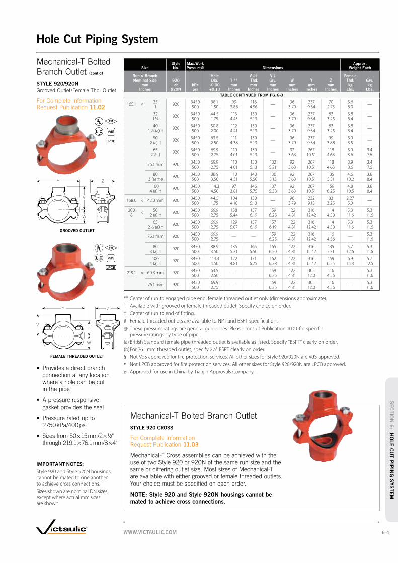
SizeStyle No.
Max. Work Pressure @ Dimensions
Approx. Weight Each
Run × Branch Nominal Size
mm Inches
920 or
920NkPa psi
Hole Dia.
-0.00 +0.13
T ** mm
Inches
V ‡ # Thd. mm
Inches
V ‡ Grv. mm
Inches
W mm
Inches
Y mm
Inches
Z mm
Inches
Female Thd. kg
Lbs.
Grv. kg
Lbs.
TABLE CONTINUED FROM PG. 6-3
165.1 × 25 920 3450 38.1 99 116 — 96 237 70 3.6 —1 500 1.50 3.88 4.56 3.79 9.34 2.75 8.0
32 920 3450 44.5 113 130 — 96 237 83 3.8 —1 ¼ 500 1.75 4.43 5.13 3.79 9.34 3.25 8.4
40 920 3450 50.8 112 130 — 96 237 83 3.8 —1 ½ (a) † 500 2.00 4.41 5.13 3.79 9.34 3.25 8.4
50 920 3450 63.5 111 130 — 96 237 99 3.9 —2 (a) † 500 2.50 4.38 5.13 3.79 9.34 3.88 8.5
65 920 3450 69.9 110 130 — 92 267 118 3.9 3.42 ½ † 500 2.75 4.01 5.13 3.63 10.51 4.63 8.6 7.6
76.1 mm 920 3450 69.9 110 130 132 92 267 118 3.9 3.4500 2.75 4.01 5.13 5.21 3.63 10.51 4.63 8.6 7.6
80 920 3450 88.9 110 140 130 92 267 135 4.6 3.83 (a) † ø 500 3.50 4.31 5.50 5.13 3.63 10.51 5.31 10.2 8.4
100 920 3450 114.3 97 146 137 92 267 159 4.8 3.84 (a) † 500 4.50 3.81 5.75 5.38 3.63 10.51 6.25 10.5 8.4
168.0 × 42.0 mm 920 3450 44.5 104 130 — 96 232 83 2.27 —500 1.75 4.10 5.13 3.79 9.13 3.25 5.0
200 × 50 920 3450 69.9 138 157 159 122 316 114 5.3 5.38 2 (a) † 500 2.75 5.44 6.19 6.25 4.81 12.42 4.50 11.6 11.6
65 920 3450 69.9 129 157 157 122 316 114 5.3 5.32 ½ (a) † 500 2.75 5.07 6.19 6.19 4.81 12.42 4.50 11.6 11.6
76.1 mm 920 3450 69.9 — — 159 122 316 116 — 5.3500 2.75 6.25 4.81 12.42 4.56 11.6
80 920 3450 88.9 135 165 165 122 316 135 5.7 5.33 (a) † 500 3.50 5.31 6.50 6.50 4.81 12.42 5.31 12.6 11.6
100 920 3450 114.3 122 171 162 122 316 159 6.9 5.74 (a) † 500 4.50 4.81 6.75 6.38 4.81 12.42 6.25 15.3 12.5
219.1 × 60.3 mm 920 3450 63.5 — — 159 122 305 116 — 5.3500 2.50 6.25 4.81 12.0 4.56 11.6
76.1 mm 920 3450 69.9 — — 159 122 305 116 — 5.3500 2.75 6.25 4.81 12.0 4.56 11.6
** Center of run to engaged pipe end, female threaded outlet only (dimensions approximate).
† Available with grooved or female threaded outlet. Specify choice on order.
‡ Center of run to end of fitting.
# Female threaded outlets are available to NPT and BSPT specifications.
@ These pressure ratings are general guidelines. Please consult Publication 10.01 for specific pressure ratings by type of pipe.
(a) British Standard female pipe threaded outlet is available as listed. Specify “BSPT” clearly on order.
(b) For 76.1 mm threaded outlet, specify 2½" BSPT clearly on order.
§ Not VdS approved for fire protection services. All other sizes for Style 920/920N are VdS approved.
¤ Not LPCB approved for fire protection services. All other sizes for Style 920/920N are LPCB approved.
ø Approved for use in China by Tianjin Approvals Company.
Y
V
W
Z
Y
TV
W
Z
Mechanical-T Bolted Branch Outlet
STYLE 920 CROSS
11.03
NOTE: Style 920 and Style 920N housings cannot be
mated to achieve cross connections.
Mechanical-T Bolted
Branch Outlet (cont'd)
STYLE 920/920N
11.02
GROOVED OUTLET
FEMALE THREADED OUTLET
IMPORTANT NOTES:
Style 920 and Style 920N housings cannot be mated to one another to achieve cross connections.
Sizes shown are nominal DN sizes, except where actual mm sizes are shown.
WWW.VICTAULIC.COM 6-4
Hole Cut Piping System
SEC
TIO
N 6
: HO
LE
CU
T P
IPIN
G S
YSTEM

SizeMax. Work Pressure Dimensions
Approx. Weight Each
Run × Branch Nominal Size
mm Inches
Hole Dimensions Vic-Let Dimensions
kPa psi *
Hole Saw Size mm
Inches
Max. Perm. Dia. mm
Inches
T ** mm
Inches
X mm
Inches
Y *** mm
Incheskg
Lbs.
100 – 200 × 15 2065 38.1 39.6 63 76 78 0.94 – 8 1/2 300 1.50 1.56 2.47 3.00 3.09 1.9
20 2065 38.1 39.6 62 76 78 0.73/4 300 1.50 1.56 2.44 3.00 3.09 1.6
250 – larger × 15 2065 38.1 39.6 63 76 76 0.910 – larger 1/2 300 1.50 1.56 2.47 3.00 3.00 1.9
20 2065 38.1 39.6 62 76 76 0.73/4 300 1.50 1.56 2.44 3.00 3.00 1.6
* On schedule 40 pipe 100 – 200 mm/4 – 8" and Schedule 10 – 40 for sizes 250 mm/10" and larger. Minimum 4.2 mm/0.165", maximum 9.5 mm/0.375" wall thickness on large pipe or flat plate. Pressure rating is for Vic-Let outlet only, pipe used must also be rated at this pressure or higher. Pressure rating is 1375 kPa/200 psi for standard wall aluminum pipe.
** Inside wall of run to engaged pipe end.
*** Width of collar is as supplied, width assembled changes due to collar deformation at assembly.
IMPORTANT NOTES:
Flow Data: Flow area equivalent to 20 mm/¾" pipe. Accepts 11 mm/7⁄16" diameter probe.
Warning: Always depressurize system and drain before disassembly.
Due to deformation of the collar, Vic-Let outlet should not be re-used after initial installation.
Sizes shown are nominal DN sizes, except where actual mm sizes are shown.
XT
Y
TX
Y
STYLE 923
11.05
TYPICAL 100 – 200 mm/4 – 8" SIZES
TYPICAL 250 mm/10" AND LARGER SIZES
TYPICAL 100 – 200 mm/4 – 8" SIZES TYPICAL 250 mm/10" AND LARGER SIZES
WWW.VICTAULIC.COM6-5
Hole Cut Piping System
SEC
TIO
N 6
: H
OLE
CU
T P
IPIN
G S
YSTEM
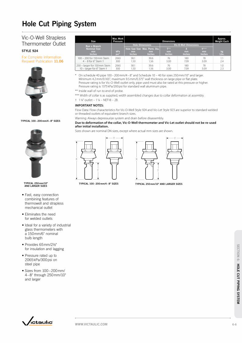
SizeMax. Work Pressure Dimensions
Approx. Weight Each
Run × Branch Nominal Size
mm Inches
Hole Dimensions Vic-O-Well Dimensions
kPa psi*
Hole Saw Size mm
Inches
Max. Perm. Dia. mm
Inches
T** mm
Inches
X mm
Inches
Y*** mm
Incheskg
Lbs.
100 – 200 for 150 mm Stem 2065 38.1 39.6 76 180 78 1.14 – 8 for 6" Stem † 300 1.50 1.56 3.00 7.09 3.09 2.4
250 – larger for 150 mm Stem 2065 38.1 39.6 76 180 78 1.0 10 – larger for 6" Stem † 300 1.50 1.56 3.00 7.09 3.09 2.3
* On schedule 40 pipe 100 – 200 mm/4 – 8" and Schedule 10 – 40 for sizes 250 mm/10" and larger. Minimum 4.2 mm/0.165", maximum 9.5 mm/0.375" wall thickness on large pipe or flat plate. Pressure rating is for Vic-O-Well outlet only, pipe used must also be rated at this pressure or higher. Pressure rating is 1375 kPa/200 psi for standard wall aluminum pipe.
** Inside wall of run to end of probe.
*** Width of collar is as supplied, width assembled changes due to collar deformation at assembly.
† 1 ¼" outlet – 1 ¼ – NEF18 – 2B.
IMPORTANT NOTES:
Flow Data: Flow characteristics for Vic-O-Well Style 924 and Vic-Let Style 923 are superior to standard welded or threaded outlets of equivalent branch sizes.
Warning: Always depressurize system and drain before disassembly.
Due to deformation of the collar, Vic-O-Well thermometer and Vic-Let outlet should not be re-used
after initial installation.
Sizes shown are nominal DN sizes, except where actual mm sizes are shown.
X
T
Y
X
T
Y
Thermometer Outlet
STYLE 924
11.06
TYPICAL 100 – 200 mm/4 – 8" SIZES
TYPICAL 250 mm/10" AND LARGER SIZES
TYPICAL 100 – 200 mm/4 – 8" SIZES TYPICAL 250 mm/10" AND LARGER SIZES
mechanical outlet
WWW.VICTAULIC.COM 6-6
Hole Cut Piping System
SEC
TIO
N 6
: HO
LE
CU
T P
IPIN
G S
YSTEM
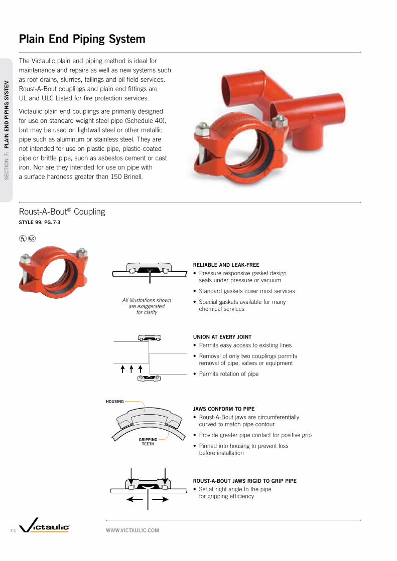
Exaggerated for clarity
HOUSING
GRIPPING TEETH
RELIABLE AND LEAK-FREE
UNION AT EVERY JOINT
JAWS CONFORM TO PIPE
ROUST-A-BOUT JAWS RIGID TO GRIP PIPE
®
STYLE 99, PG. 7-3
All illustrations shown are exaggerated
for clarity
WWW.VICTAULIC.COM7-1
Plain End Piping System
SEC
TIO
N 7
: P
LAIN
EN
D P
IPIN
G S
YSTEM

SizeTangent Length
Nominal Size mm
Inches
Actual Outside Dia.
mm Inches
T Minimum
mm Inches
40 48.3 381 1/2 1.900 1.50
50 60.3 452 2.375 1.75
65 73.0 452 1/2 2.875 1.75
80 88.9 453 3.500 1.75
90 101.6 453 1/2 4.000 1.75
100 114.3 514 4.500 2.00
125 141.3 545 5.563 2.13
IMPORTANT NOTES:
Sizes shown are nominal DN sizes, except where actual mm sizes are shown.
SizeTangent Length
Nominal Size mm
Inches
Actual Outside Dia.
mm Inches
T Minimum
mm Inches
165.1 mm165.1 546.500 2.13
150 168.3 546 6.625 2.13
200 219.1 578 8.625 2.25
250 273.0 5710 1.750 2.25
300 323.9 5712 12.750 2.25
350 355.6 5714 14.000 2.25
400 406.4 5716 16.000 2.25
T
T
T
T
PRODUCTS
7-1 Plain End Piping SystemNO. 10P, PG. 7-4
NO. 100P, PG. 7-4
NO. 10P, PG. 7-4
NO. 11P, PG. 7-4
NO. 110P, PG. 7-4
NO. 11P, PG. 7-4
NO. 20P, PG. 7-5
NO. 35P, PG. 7-5
NO. 33P, PG. 7-5
NO. 30P, PG. 7-6
NO. 25P, PG. 7-6 NO. 61P, PG. 7-5
NO. 53P, PG. 7-7
NO. 42P, PG. 7-8
NO. 40P, PG. 7-8
NO. 43P, PG. 7-8
WWW.VICTAULIC.COM 7-2
Plain End Piping System
SEC
TIO
N 7
: PLAIN
EN
D P
IPIN
G S
YSTEM

SizeMax. Work Pressure*
Max. End Load* Dimensions
Approx. Weight Each
Nominal Size mm
Inches
Actual Outside Dia.
mm Inches
kPa psi
kg Lbs.
X mm
Inches
Y mm
Inches
Z mm
Incheskg
Lbs.
25 33.7 4130 3560 65 108 57 0.81 1.315 600 800 2.56 4.25 2.25 1.7
40 48.3 5175 9345 83 140 73 1.61 1/2 1.900 750 2100 3.25 5.50 2.88 3.6
50 60.3 5175 14685 95 171 86 2.42 2.375 750 3300 3.75 6.75 3.38 5.3
65 73.0 4130 17310 108 181 86 2.52 1/2 2.875 600 3890 4.25 7.13 3.38 5.7
76.1 mm 76.1 2700 12500 119 159 70 2.03.000 400 2825 4.69 6.25 2.75 4.4
80 88.9 4130 25676 127 216 86 3.93 3.500 600 5770 5.00 8.50 3.38 8.7
90 101.6 3450 27946 140 235 92 4.83 1/2 4.000 500 6280 5.50 9.25 3.63 10.6
100 114.3 3100 31840 156 254 102 5.84 4.500 450 7155 6.13 10.00 4.00 12.8
139.7 mm 139.7 1700 26440 200 260 81 4.15.500 250 5940 7.80 10.75 3.19 9.0
125 141.3 2400 37825 184 289 111 7.85 5.563 350 8500 7.25 11.38 4.38 17.3
165.1 mm 165.1 2065 44300 213 337 111 10.16.500 300 9955 8.38 13.25 4.38 22.2
150 168.3 2065 46013 216 340 111 10.56 6.625 300 10340 850 13.38 4.38 23.2
200 219.1 1700 64970 276 365 127 16.98 8.625 250 14600 10.88 14.38 5.00 37.2
250 273.0 1700 101015 340 416 127 21.910 10.750 250 22700 13.38 16.38 5.00 48.2
300 323.9 1700 141955 394 499 130 27.212 12.750 250 31900 15.50 19.63 5.13 60.0
350 355.6 1400 137060 425 527 137 40.414 14.000 200 30800 16.75 20.75 5.38 89.0
400 406.4 1000 134390 483 575 137 47.616 16.000 150 30200 19.00 22.63 5.38 105.0
450 457.0 1000 169990 533 597 137 56.718 18.000 150 38200 21.00 23.50 5.38 125.0
* Working Pressure and End Load are total, from all internal and external loads, based on coupling properly assembled, with bolts fully torqued to listed specifications, on plain end or beveled end standard weight (ANSI) steel pipe and Victaulic plain end fittings. Couplings are designed to be used with plain end pipe and Victaulic plain end fittings only.
IMPORTANT NOTES:
Sizes shown are nominal DN sizes, except where actual mm sizes are shown.
Y Z
X
Y Z
X
ZY
X
STYLE 99
14.02
TYPICAL 25 – 150 mm/1 – 6" SIZES TYPICAL 200 – 300 mm/8 – 12" SIZES TYPICAL 350 – 450 mm/14 – 18" SIZES
WWW.VICTAULIC.COM7-3
SEC
TIO
N 7
: P
LAIN
EN
D P
IPIN
G S
YSTEM
Plain End Piping System – Couplings
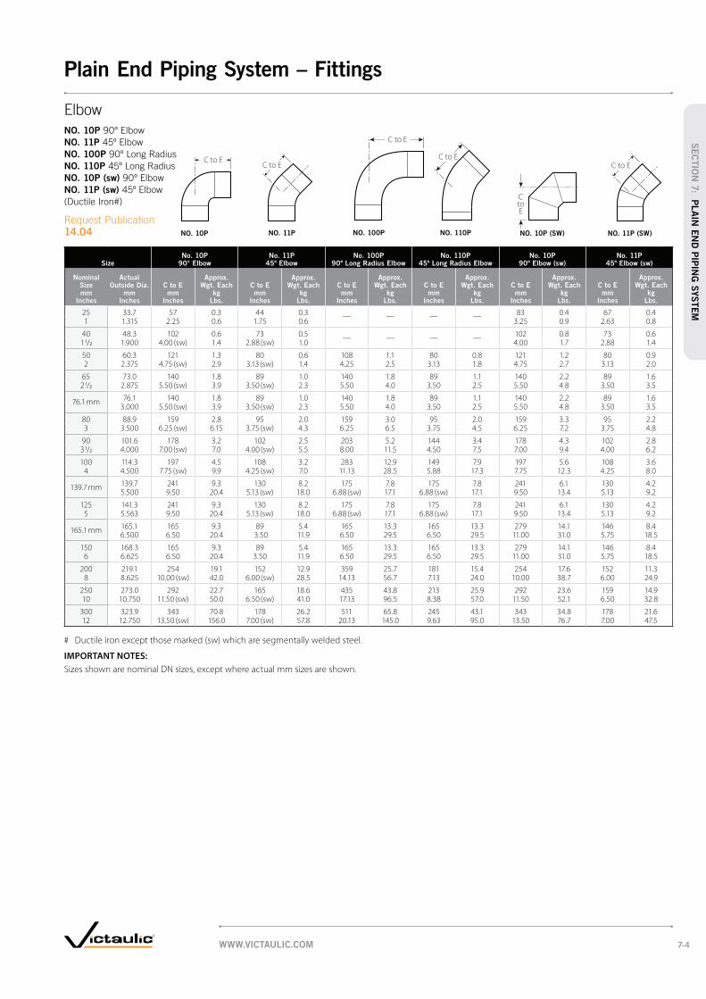
SizeNo. 10P
90° ElbowNo. 11P
45º ElbowNo. 100P
90º Long Radius ElbowNo. 110P
45º Long Radius ElbowNo. 10P
90º Elbow (sw)No. 11P
45º Elbow (sw)
Nominal Size mm
Inches
Actual Outside Dia.
mm Inches
C to E mm
Inches
Approx. Wgt. Each
kg Lbs.
C to E mm
Inches
Approx. Wgt. Each
kg Lbs.
C to E mm
Inches
Approx. Wgt. Each
kg Lbs.
C to E mm
Inches
Approx. Wgt. Each
kg Lbs.
C to E mm
Inches
Approx. Wgt. Each
kg Lbs.
C to E mm
Inches
Approx. Wgt. Each
kg Lbs.
25 33.7 57 0.3 44 0.3 — — — — 83 0.4 67 0.41 1.315 2.25 0.6 1.75 0.6 3.25 0.9 2.63 0.8
40 48.3 102 0.6 73 0.5 — — — — 102 0.8 73 0.61 1/2 1.900 4.00 (sw) 1.4 2.88 (sw) 1.0 4.00 1.7 2.88 1.4
50 60.3 121 1.3 80 0.6 108 1.1 80 0.8 121 1.2 80 0.92 2.375 4.75 (sw) 2.9 3.13 (sw) 1.4 4.25 2.5 3.13 1.8 4.75 2.7 3.13 2.0
65 73.0 140 1.8 89 1.0 140 1.8 89 1.1 140 2.2 89 1.62 1/2 2.875 5.50 (sw) 3.9 3.50 (sw) 2.3 5.50 4.0 3.50 2.5 5.50 4.8 3.50 3.5
76.1 mm 76.1 140 1.8 89 1.0 140 1.8 89 1.1 140 2.2 89 1.63.000 5.50 (sw) 3.9 3.50 (sw) 2.3 5.50 4.0 3.50 2.5 5.50 4.8 3.50 3.5
80 88.9 159 2.8 95 2.0 159 3.0 95 2.0 159 3.3 95 2.23 3.500 6.25 (sw) 6.15 3.75 (sw) 4.3 6.25 6.5 3.75 4.5 6.25 7.2 3.75 4.8
90 101.6 178 3.2 102 2.5 203 5.2 144 3.4 178 4.3 102 2.83 1/2 4.000 7.00 (sw) 7.0 4.00 (sw) 5.5 8.00 11.5 4.50 7.5 7.00 9.4 4.00 6.2
100 114.3 197 4.5 108 3.2 283 12.9 149 7.9 197 5.6 108 3.64 4.500 7.75 (sw) 9.9 4.25 (sw) 7.0 11.13 28.5 5.88 17.3 7.75 12.3 4.25 8.0
139.7 mm 139.7 241 9.3 130 8.2 175 7.8 175 7.8 241 6.1 130 4.25.500 9.50 20.4 5.13 (sw) 18.0 6.88 (sw) 17.1 6.88 (sw) 17.1 9.50 13.4 5.13 9.2
125 141.3 241 9.3 130 8.2 175 7.8 175 7.8 241 6.1 130 4.25 5.563 9.50 20.4 5.13 (sw) 18.0 6.88 (sw) 17.1 6.88 (sw) 17.1 9.50 13.4 5.13 9.2
165.1 mm 165.1 165 9.3 89 5.4 165 13.3 165 13.3 279 14.1 146 8.46.500 6.50 20.4 3.50 11.9 6.50 29.5 6.50 29.5 11.00 31.0 5.75 18.5
150 168.3 165 9.3 89 5.4 165 13.3 165 13.3 279 14.1 146 8.46 6.625 6.50 20.4 3.50 11.9 6.50 29.5 6.50 29.5 11.00 31.0 5.75 18.5
200 219.1 254 19.1 152 12.9 359 25.7 181 15.4 254 17.6 152 11.38 8.625 10.00 (sw) 42.0 6.00 (sw) 28.5 14.13 56.7 7.13 24.0 10.00 38.7 6.00 24.9
250 273.0 292 22.7 165 18.6 435 43.8 213 25.9 292 23.6 159 14.910 10.750 11.50 (sw) 50.0 6.50 (sw) 41.0 17.13 96.5 8.38 57.0 11.50 52.1 6.50 32.8
300 323.9 343 70.8 178 26.2 511 65.8 245 43.1 343 34.8 178 21.612 12.750 13.50 (sw) 156.0 7.00 (sw) 57.8 20.13 145.0 9.63 95.0 13.50 76.7 7.00 47.5
# Ductile iron except those marked (sw) which are segmentally welded steel.
IMPORTANT NOTES:
Sizes shown are nominal DN sizes, except where actual mm sizes are shown.
C to E
C to E
C to E
CtoE
C to EC to E
NO. 10P
NO. 11P
NO. 100P
NO. 110P
NO. 10P (sw)
NO. 11P (sw)
14.04 NO. 10P NO. 11P NO. 100P NO. 110P NO. 11P (SW)NO. 10P (SW)
WWW.VICTAULIC.COM 7-4
SEC
TIO
N 7
: PLAIN
EN
D P
IPIN
G S
YSTEM
Plain End Piping System – Fittings

SizeNo. 20P
TeeNo. 35P (sw)
CrossNo. 33P (sw)
True WyeNo. 61P
Steel Bull Plug
Nominal Size mm
Inches
Actual Outside Dia.
mm Inches
C to E mm
Inches
Approx. Wgt. Each
kg Lbs.
C to E mm
Inches
Approx. Wgt. Each
kg Lbs.
C to LE mm
Inches
C to SE mm
Inches
Approx. Wgt. Each
kg Lbs.
E to E mm
Inches
Approx. Wgt. Each
kg Lbs.
25 33.7 57 0.5 83 0.8 83 57 0.5 76 0.31 1.315 2.25 1.0 3.25 1.7 3.25 2.25 1.1 3.00 0.7
40 48.3 70 0.8 102 1.6 102 70 0.8 89 0.51 1/2 1.900 2.75 (sw) 1.7 4.00 3.5 4.00 2.75 1.8 3.50 1.2
50 60.3 83 1.4 108 2.4 108 70 1.3 102 0.92 2.375 3.25 (sw) 3.0 4.25 5.2 4.25 2.75 2.9 4.00 2.0
65 73.0 95 3.1 121 2.4 121 76 4.1 127 1.42 1/2 2.875 3.75 (sw) 6.8 4.75 5.4 4.75 3.00 9.0 5.00 3.0
80 88.9 108 4.1 130 3.9 130 83 3.9 152 2.03 3.500 4.25 (sw) 9.0 5.13 8.5 5.13 3.25 8.5 6.00 4.5
90 101.6 140 5.7 140 4.1 140 89 4.5 165 2.73 1/2 4.000 5.50 (sw) 12.5 5.50 9.0 5.50 3.50 10.0 6.50 6.0
100 114.3 127 5.4 149 4.9 149 95 6.4 178 3.44 4.500 5.00 11.9 5.88 10.8 5.88 3.75 14.0 7.00 7.5
125 141.3 175 7.8 175 9.1 175 102 9.8 216 5.25 5.563 6.88 (sw) 17.1 6.88 20.0 6.88 4.00 21.6 8.50 11.5
150 168.3 165 13.3 194 13.6 194 114 14.2 254 7.76 6.625 6.50 29.5 7.63 30.0 7.63 4.50 31.2 10.00 17.0
200 219.1 254 32.4 254 30.1 254 152 16.3 279 13.28 8.625 10.00 (sw) 71.5 10.00 66.4 10.00 6.00 36.0 11.00 29.0
250 273.0 292 52.6 292 46.7 292 165 23.6 330 21.810 10.750 11.50 (sw) 116.0 11.50 103.0 11.50 6.50 52.0 13.00 48.0
300 323.9 343 54.4 343 71.7 343 178 36.8 356 27.212 12.750 13.50 (sw) 120.0 13.50 158.0 13.50 7.00 81.2 14.00 60.0
# Ductile iron except those marked (sw) which are segmentally welded steel.
IMPORTANT NOTES:
Sizes shown are nominal DN sizes, except where actual mm sizes are shown.
C to EC to LE
C toSE
C to E
E to E
NO. 20P
NO. 35P (sw)
NO. 33P (sw)
NO. 61P
14.04
NO. 20P NO. 35P (SW) NO. 61PNO. 33P (SW)
WWW.VICTAULIC.COM7-5
SEC
TIO
N 7
: P
LAIN
EN
D P
IPIN
G S
YSTEM
Plain End Piping System – Fittings

SizeNo. 30P (sw) 45º Lateral
Nominal Size mm
Inches
Actual Outside Diameter
mm Inches
C to LE mm
Inches
C to SE mm
Inches
Approx. Weight Each
kg Lbs.
25 33.7 127 57 1.61 1.315 5.00 2.25 3.5
40 48.3 159 70 1.61 1/2 1.900 6.25 2.75 3.5
50 60.3 184 70 2.32 2.375 7.25 2.75 5.1
65 73.0 197 76 4.22 1/2 2.875 7.75 3.00 9.3
80 88.9 222 83 5.83 3.500 8.75 3.25 12.8
90 101.6 254 89 9.13 1/2 4.000 10.00 3.50 20.0
100 114.3 263 95 8.64 4.500 10.75 3.75 19.0
125 141.3 324 102 13.65 5.563 12.75 4.00 30.0
150 168.3 356 114 19.66 6.625 14.00 4.50 43.3
200 219.1 457 152 41.78 8.625 18.00 6.00 92.0
250 273.0 527 165 48.110 10.750 20.75 6.50 106.0
300 323.9 622 178 75.812 12.750 24.50 7.00 167.0
IMPORTANT NOTES:
Sizes shown are nominal DN sizes, except where actual mm sizes are shown.
SizeNo. 25P
Reducing Tee
Nominal Size mm
Inches
C to E mm
Inches
Approx. Weight Each
kg Lbs.
40 × 40 × 25 102 1.01 1/2 1 1/2 1 4.00 2.2
50 × 50 × 25 108 1.32 2 1 4.25 2.9
40 108 1.41 1/2 4.25 3.1
80 × 80 × 25 130 3.03 3 1 5.13 6.7
40 130 3.11 1/2 5.13 6.9
50 130 3.22 5.13 7.1
100 × 100 × 25 149 4.94 4 1 5.88 10.9
40 149 5.01 1/2 5.88 11.1
50 149 5.12 5.88 11.3
65 149 5.32 1/2 5.88 11.6
80 149 5.43 5.88 11.9
150 × 150 × 50 194 11.26 6 2 7.63 24.7
80 194 11.53 7.63 25.4
100 194 11.94 7.63 26.2
200 × 200 × 50 254 15.28 8 2 10.00 42.0
80 254 20.03 10.00 44.0
100 254 20.94 10.00 46.0
125 254 21.85 10.00 48.0
150 254 22.76 10.00 50.0
250 × 250 × 100 292 33.610 10 4 11.50 74.0
150 292 35.46 11.50 78.0
200 292 39.08 11.50 86.0
300 × 300 × 150 343 50.812 12 6 13.50 112.0
200 343 53.58 13.50 118.0
250 343 59.010 13.50 130.0
IMPORTANT NOTES:
Sizes shown are nominal DN sizes, except where actual mm sizes are shown.
C to E
C toLE
C toSE
NO. 25P
14.04
NO. 25P
NO. 30P (SW)
14.04
NO. 30P (SW)
WWW.VICTAULIC.COM 7-6
SEC
TIO
N 7
: PLAIN
EN
D P
IPIN
G S
YSTEM
Plain End Piping System – Fittings

SizeNo. 53P
Swaged Nipple
Nominal Size mm
Inches
E to E mm
Inches
Approx. Weight Each
kg Lbs.
150 × 25 305 7.36 1 12.00 16.0
40 305 7.31 1/2 12.00 16.0
50 305 7.72 12.00 17.0
65 305 7.72 1/2 12.00 17.0
80 305 7.73 12.00 17.0
90 305 7.73 1/2 12.00 17.0
100 305 7.74 12.00 17.0
125 305 7.75 12.00 17.0
200 × 80 330 13.28 3 13.00 29.0
100 330 13.24 13.00 29.0
125 330 13.25 13.00 29.0
150 330 21.86 13.00 48.0
250 × 80 381 21.810 3 15.00 48.0
100 381 21.84 15.00 48.0
150 381 21.86 15.00 48.0
200 381 21.88 15.00 48.0
300 × 150 406 26.812 6 16.00 59.0
200 406 26.88 16.00 59.0
250 406 26.810 16.00 59.0
IMPORTANT NOTES:
Sizes shown are nominal DN sizes, except where actual mm sizes are shown.
SizeNo. 53P
Swaged Nipple
Nominal Size mm
Inches
E to E mm
Inches
Approx. Weight Each
kg Lbs.
40 × 25 114 0.61 1/2 1 4.50 1.2
50 × 25 165 0.92 1 6.50 2.0
40 165 0.91 1/2 6.50 2.0
65 × 25 178 1.42 1/2 1 7.00 3.0
40 178 1.41 1/2 7.00 3.0
50 178 1.42 7.00 3.0
80 × 25 203 2.03 1 8.0 4.5
40 203 2.01 1/2 8.00 4.5
50 203 2.02 8.00 4.5
65 203 2.02 1/2 8.00 4.5
90 × 80 203 3.13 1/2 3 8.00 6.8
100 × 25 229 3.44 1 9.00 7.5
40 229 3.41 1/2 9.00 7.5
50 229 3.42 9.00 7.5
65 229 3.42 1/2 9.00 7.5
80 229 3.43 9.00 7.5
90 229 3.43 1/2 9.00 7.5
125 × 50 279 5.25 2 11.00 11.5
80 279 5.23 11.00 11.5
100 279 5.24 11.00 11.5
E to E
NO. 53P
14.04
NO. 53P
WWW.VICTAULIC.COM7-7
SEC
TIO
N 7
: P
LAIN
EN
D P
IPIN
G S
YSTEM
Plain End Piping System – Fittings

Size DimensionsApprox.
Weight Each
Nominal Size mm
Inches
Actual Outside Diameter
mm Inches
E to E mm
Incheskg
Lbs.
25 33.7 76 0.41 1.315 3.00 0.9
40 48.3 102 0.41 1/2 1.900 4.00 0.9
50 60.3 102 0.52 2.375 4.00 1.2
65 73.0 102 0.92 1/2 2.875 4.00 1.9
80 88.9 102 1.13 3.500 4.00 2.5
100 114.3 152 2.54 4.500 6.00 5.4
150 168.3 152 4.36 6.625 6.00 9.4
@ Available with British Standard Pipe Threads, specify “BSP” clearly on order.
IMPORTANT NOTES:
Sizes shown are nominal DN sizes, except where actual mm sizes are shown.
E to E E to EE to E
NO. 40P
NO. 42P
NO. 43P
14.04
NO. 40P @ NO. 42P NO. 43P
WWW.VICTAULIC.COM 7-8
SEC
TIO
N 7
: PLAIN
EN
D P
IPIN
G S
YSTEM
Plain End Piping System – Fittings

Rigid CouplingSTYLE 489, PG. 8-3
Rigid Coupling STYLE 89, PG. 8-4 AGS STYLE W89, PG. 5-4
Flexible CouplingSTYLE 77S, PG. 8-5
Flexible CouplingSTYLE 475, PG. 8-6
STYLE 441N, PG. 8-7
WWW.VICTAULIC.COM8-1
Grooved System for Stainless Steel Pipe
SEC
TIO
N 8
: G
RO
OVED
SYSTEM
FO
R S
S P
IPE

SERIES 763, PG. 8-11 SERIES 726S, PG. 8-10
PRODUCTS
8-1 Grooved System for
Stainless Steel Pipe
NO. 410 SS, PG. 8-8
NO. 420 SS, PG. 8-8
NO. 411 SS, PG. 8-8
NO. 425 SS, PG. 8-9
NO. 450 SS, PG. 8-9
NO. 460 SS, PG. 8-8
NO. 100 SS, PG. 8-8
NO. 110 SS, PG. 8-8
WWW.VICTAULIC.COM 8-2
Grooved System for Stainless Steel Pipe
SEC
TIO
N 8
: GR
OO
VED
SYSTEM
FO
R S
S P
IPE

SizeMax. End Load *
Allow. Pipe End Sep. * Dimensions
Approx. Wgt. Each
Nominal Size mm
Inches
Actual Outside Dia.
mm Inches
N Lbs.
mm Inches
X mm
Inches
Y mm
Inches
Z mm
Incheskg
Lbs.Schedule
40SSchedule
10SSchedule
5S
40 48.3 7565 3783 2537 1.3 73 118 47 0.71 1/2 1.900 1700 850 570 0.05 2.86 4.42 1.84 1.6
50 60.3 11837 5919 3961 1.3 85 132 47 0.72 2.375 2660 1330 890 0.05 3.34 5.19 1.86 1.6
65 73.0 17355 8678 5785 1.3 100 143 47 0.92 1/2 2.875 3900 1950 1300 0.05 3.92 5.62 1.86 1.9
76.1 mm 76.1 18868 9434 6297 1.3 102 145 47 0.93.000 4240 2120 1415 0.05 4.02 5.72 1.86 2.0
80 88.9 25699 12861 8566 1.3 115 172 47 1.33 3.500 5775 2890 1925 0.05 4.54 6.78 1.86 2.8
100 114.3 42453 21249 14151 4.8 147 201 53 1.84 4.500 9540 4775 3180 0.19 5.77 7.90 2.07 4.0
139.7 mm 139.7 63413 31729 21138 6.4 180 283 60 5.55.500 14250 7130 4750 0.25 7.07 11.13 2.38 12.0
165.1 mm 165.1 88600 44300 29548 6.4 207 321 64 7.06.500 19910 9955 6640 0.25 8.16 12.68 2.50 15.5
150 168.3 92026 46015 30685 6.4 207 321 64 7.06 6.625 20680 10340 6895 0.25 8.16 12.68 2.50 15.5
216.3 mm 216.3 152079 76051 50686 6.4 270 381 70 10.98.515 34175 17090 11390 0.25 10.63 15.00 2.75 24.0
200 219.1 155995 78010 52000 6.4 270 381 70 10.98 8.625 35055 17530 11685 0.25 10.63 15.00 2.75 24.0
267.4 mm 267.4 232424 116212 77475 6.4 332 438 76 15.010.528 52230 26115 17410 0.25 13.09 17.25 3.00 33.0
250 273.0 242345 121175 80770 6.4 332 438 76 15.010 10.750 54460 27230 18150 0.25 13.09 17.25 3.00 33.0
318.5 mm 318.5 329745 164873 109915 6.4 384 486 80 18.112.539 74100 37050 24700 0.25 15.13 19.13 3.13 40.0
300 323.9 340890 170435 113630 6.4 384 486 80 18.112 12.750 76605 38300 25535 0.25 15.13 19.13 3.13 40.0
* Refer to General Notes on pg. 1-15.
IMPORTANT NOTES:
Sizes shown are nominal DN sizes, except where actual mm sizes are shown.
Y Z
X
Y
X
Z
Rigid Coupling
STYLE 489
17.25
TYPICAL 139.7 – 300 mm/6 – 12" SIZESTYPICAL 40 – 100 mm/1½ – 4" SIZES
WWW.VICTAULIC.COM8-3
SEC
TIO
N 8
: G
RO
OVED
SYSTEM
FO
R S
S P
IPE
Grooved System for Stainless Steel Pipe – Couplings
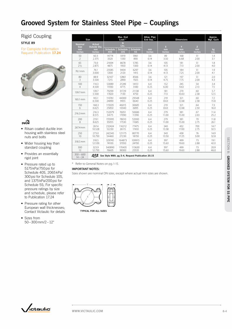
SizeMax. End Load *
Allow. Pipe End Sep. * Dimensions
Approx. Wgt. Each
Nominal Size mm
Inches
Actual Outside Dia.
mm Inches
N Lbs.
mm Inches
X mm
Inches
Y mm
Inches
Z mm
Incheskg
Lbs.Schedule
40SSchedule
10SSchedule
5S
50 60.3 14774 5919 3961 3.6 89 168 51 1.42 2.375 3320 1330 890 0.14 3.50 6.68 2.00 3.1
65 73.0 21694 8678 5785 3.6 105 181 51 1.82 1/2 2.875 4875 1950 1300 0.14 4.13 7.13 2.00 4.0
76.1 mm 76.1 23585 9434 6297 3.6 105 184 51 1.93.000 5300 2120 1415 0.14 4.13 7.25 2.00 4.1
80 88.9 32107 12861 8566 3.6 121 197 51 2.03 3.500 7215 2890 1925 0.14 4.75 7.75 2.00 4.3
100 114.3 53089 21249 14151 6.4 152 245 54 3.44 4.500 11930 4775 3180 0.25 6.00 9.63 2.13 7.5
139.7 mm 139.7 79299 31729 21138 6.4 181 270 60 5.75.500 17820 7130 4750 0.25 7.13 10.63 2.38 12.5
165.1 mm 165.1 110761 44300 29548 6.4 219 321 60 7.26.500 24890 9955 6640 0.25 8.63 12.68 2.38 15.8
150 168.3 115035 46015 30685 6.4 219 321 64 7.36 6.625 25850 10340 6895 0.25 8.63 12.68 2.50 16.0
216.3 mm 216.3 152079 76051 50686 6.4 279 381 67 11.48.515 34175 17090 11390 0.25 11.00 15.00 2.63 25.2
200 219.1 155995 78010 52000 6.4 279 381 70 11.88 8.625 35055 17530 11685 0.25 11.00 15.00 2.75 26.1
267.4 mm 267.4 232424 116212 77475 6.4 340 432 700 14.710.528 52230 26115 17410 0.25 13.38 17.00 2.75 32.5
250 273.0 242345 121175 80770 6.4 343 438 76 14.910 10.750 54460 27230 18150 0.25 13.50 17.25 3.00 32.8
318.5 mm 318.5 329745 164873 109915 6.4 397 499 73 19.112.539 74100 37050 24700 0.25 15.63 19.63 2.88 42.0
300 323.9 340890 170435 113630 6.4 397 499 73 20.912 12.750 76605 38300 25535 0.25 15.63 19.63 2.88 46.0
350 – 600 14 – 24
See Style W89, pg. 5-4, Request Publication 20.15
* Refer to General Notes on pg. 1-15.
IMPORTANT NOTES:
Sizes shown are nominal DN sizes, except where actual mm sizes are shown.
Y Z
X
Rigid Coupling
STYLE 89
17.24
TYPICAL FOR ALL SIZES
WWW.VICTAULIC.COM 8-4
SEC
TIO
N 8
: GR
OO
VED
SYSTEM
FO
R S
S P
IPE
Grooved System for Stainless Steel Pipe – Couplings

SizeMax. End Load *
Allow. Pipe End Sep. * Dimensions
Approx. Wgt. Each
Nominal Size mm
Inches
Actual Outside Dia.
mm Inches
N Lbs.
mm Inches
X mm
Inches
Y mm
Inches
Z mm
Incheskg
Lbs.Schedule
40SSchedule
10SSchedule
5S
20 26.9 2893 1915 1245 0 – 1.6 53 99 43 0.63/4 1.050 650 430 280 0 – 0.06 2.08 3.89 1.70 1.2
25 33.7 4450 3025 1960 0 – 1.6 65 114 42 0.71 1.315 1000 680 440 0 – 0.06 2.54 4.50 1.66 1.6
32 42.4 7120 4805 3115 0 – 1.6 73 122 45 0.91 1/4 1.900 1600 1080 700 0 – 0.06 2.87 4.79 1.76 1.9
40 48.3 9345 6295 4095 0 – 1.6 82 122 45 1.01 1/2 1.900 2100 1415 920 0 – 0.06 3.24 4.80 1.76 2.1
50 60.3 14685 9855 6408 0 – 1.6 94 135 47 1.12 2.375 330 2215 1440 0 – 0.06 3.70 5.33 1.84 2.5
65 73.0 21805 14440 9390 0 – 1.6 107 147 47 1.32 1/2 2.875 4900 3245 2110 0 – 0.06 4.20 5.79 1.84 2.9
80 88.9 32040 17133 10702 0 – 1.6 123 178 47 1.93 3.500 7200 3850 2405 0 – 0.06 4.83 6.99 1.84 4.1
100 114.3 28302 24764 15931 0 – 3.2 151 208 52 3.04 4.500 6360 5565 3580 0 – 0.13 5.93 8.20 2.06 6.7
150 168.3 46013 30705 19135 0 – 3.2 211 281 52 3.96 6.625 10340 6900 4300 0 – 0.13 8.30 11.06 2.06 8.5
200 219.1 77986 32485 19491 0 – 3.2 229 374 62 10.78 8.625 17525 7300 4380 0 – 0.13 11.38 14.74 2.44 23.5
250 273.0 121151 30305 20203 0 – 3.2 343 440 67 15.010 10.750 27225 6810 4540 0 – 0.13 13.50 17.33 2.63 33.0
300 323.9 170435 71022 42609 0 – 3.2 394 486 65 15.912 12.750 38300 15960 9575 0 – 0.13 15.50 19.15 2.56 35.0
350 355.6 137060 68530 44500 0 – 3.2 421 519 71 16.814 † 14.000 30800 15400 10000 0 – 0.13 16.56 20.44 2.81 37.0
400 406.4 134390 71556 46725 0 – 3.2 481 572 75 24.016 † 16.000 30200 16080 10500 0 – 0.13 18.94 22.52 2.94 53.0
450 457.0 141510 68085 45390 0 – 3.2 540 625 78 25.018 † 18.000 31800 15300 10200 0 – 0.13 21.25 24.62 3.06 62.0
* Refer to General Notes on pg. 1-15.
† Not for use with AGS (Advance Groove System) products.
IMPORTANT NOTES:
Sizes shown are nominal DN sizes, except where actual mm sizes are shown.
ZY
X
X
Y Z
Flexible Coupling
STYLE 77S
17.03
TYPICAL 20 – 350 mm/¾ – 14" SIZES TYPICAL 400 – 450 mm/16 – 18" SIZES
WWW.VICTAULIC.COM8-5
SEC
TIO
N 8
: G
RO
OVED
SYSTEM
FO
R S
S P
IPE
Grooved System for Stainless Steel Pipe – Couplings

SizeMax. End Load *
Allow. Pipe End Sep. * Dimensions
Approx. Wgt. Each
Nominal Size mm
Inches
Actual Outside Dia.
mm Inches
N Lbs.
mm Inches
X mm
Inches
Y mm
Inches
Z mm
Incheskg
Lbs.Schedule
40SSchedule
10SSchedule
5S
25 33.7 4539 3026 1958 0 – 1.6 62 111 41 0.71 1.315 1020 680 440 0 – 0.06 2.45 4.36 1.63 1.6
32 42.4 7231 4806 3115 0 – 1.6 72 119 44 1.11 1/4 1.660 1625 1080 700 0 – 0.06 2.84 4.67 1.72 2.4
40 48.3 9456 6295 4094 0 – 1.6 82 120 44 1.21 1/2 1.900 2125 1415 920 0 – 0.06 3.22 4.74 1.72 2.6
50 60.3 9857 6898 4450 0 – 1.6 84 128 46 0.82 2.375 2215 1550 1000 0 – 0.06 3.30 5.03 1.80 1.7
65 73.0 14463 10124 6497 0 – 1.6 99 142 46 0.92 1/2 2.875 3250 2275 1460 0 – 0.06 3.88 5.59 1.80 1.9
76.1 mm 76.1 15731 11014 7076 0 – 1.6 102 146 46 0.93.000 3535 2475 1590 0 – 0.06 4.00 5.73 1.80 2.0
80 88.9 21405 14997 9657 0 – 1.6 114 169 46 1.33 3.500 4810 33770 2170 0 – 0.06 4.50 6.67 1.80 2.9
100 114.3 23007 21250 14150 0 – 3.2 146 202 51 1.94 4.500 5170 4775 3180 0 – 0.13 5.75 7.96 2.00 4.2
139.7 mm 139.7 21138 21138 13217 0 – 3.2 173 228 51 2.25.500 4750 4750 2970 0 – 0.13 6.81 8.97 2.00 4.9
165.1 mm ‡ 165.1 29550 29550 18470 0 – 3.2 200 268 51 3.16.500 6640 6640 4150 0 – 0.13 7.87 10.53 2.00 6.8
* Refer to General Notes on pg. 1-15.
‡ Denotes JIS pipe size.
IMPORTANT NOTES:
Sizes shown are nominal DN sizes, except where actual mm sizes are shown.
ZY
X
Flexible Coupling
STYLE 475
17.14
TYPICAL FOR ALL SIZES
WWW.VICTAULIC.COM 8-6
SEC
TIO
N 8
: GR
OO
VED
SYSTEM
FO
R S
S P
IPE
Grooved System for Stainless Steel Pipe – Couplings

Size
Style 441N PN10
Flange Adapter
Style 441N PN16
Flange Adapter
Nominal Size mm
Inches
Actual Outside Diameter
mm Inches
E to E mm
Inches
Approx. Weight Each
kg Lbs.
E to E mm
Inches
Approx. Weight Each
kg Lbs.
DN50 60.3 64 + 64 +2 2.375 2.52 2.52
DN65 76.1 mm64 + 64 +
2.52 2.52
DN80 88.9 64 + 64 +3 3.500 2.52 2.52
DN100 114.3 76 + 76 +4 4.500 2.99 2.99
DN125 139.7 mm76 + 76 +
2.99 2.99
DN125 141.3 76 + 76 +5 5.563 2.99 2.99
DN150 168.3 89 + 89 +6 6.625 3.50 3.50
DN200 219.1 102 + 102 +8 8.625 4.02 4.02
DN250 273.0 127 + 127 +10 10.750 5.00 5.00
DN300 323.9 152 + 152 +12 12.750 5.98 5.98
+ Contact Victaulic for details.
IMPORTANT NOTES:
All sizes listed except 141.3 mm are supplied with an aluminum flange according to DIN 2642 PN 10/16 type C. Roll grooved nipples are ANSI B16.9 stub end 316L (1.4404) Schedule 10S, except for sizes 76.1 and 139.7 mm, which have a pressed collar NF E 29251 with welded nipple 316L (1.4404).
Sizes shown are nominal DN sizes, except where actual mm sizes are shown.
E to E E to E
STYLE 441N
STYLE 441N PN10 STYLE 441N PN16
WWW.VICTAULIC.COM8-7
SEC
TIO
N 8
: G
RO
OVED
SYSTEM
FO
R S
S P
IPE
Grooved System for Stainless Steel Pipe – Couplings

SizeNo. 410 SS 90° Elbow
No. 411 SS 45° Elbow
No. 100 SS 90° Long Radius Elbow
No. 110 SS 45° Long Radius Elbow
No. 420 SS Tee
No. 460 SS Cap
Nominal Size mm
Inches
Actual Outside Dia.
mm Inches
C to E mm
Inches
Approx. Weight Each
kg Lbs.
C to E mm
Inches
Approx. Weight Each
kg Lbs.
C to E mm
Inches
Approx. Weight Each
kg Lbs.
C to E mm
Inches
Approx. Weight Each
kg Lbs.
C to E mm
Inches
Approx. Weight Each
kg Lbs.
T Thickness
Actual mm
Approx. Weight Each
kg Lbs.
50 60.3 83 0.5 51 0.3 — — — — 83 0.6 24 0.252 2.375 3.27 1.1 2.00 0.7 3.27 1.3 1.00 0.55
65 73.0 127 1.0 71 0.4 — — — — 78 1.0 27 0.452 1/2 2.875 5.00 2.2 2.80 0.9 3.07 2.2 1.06 1.0
76.1 76.1 95 1.1 57 0.9 — — — — 95 2.1 26 0.433 3.000 3.74 2.4 2.24 2.0 3.74 4.6 1.03 1.0
80 88.9 114 1.2 51 0.6 114.3 1.2 51 0.6 96 1.4 31 0.53 3.500 4.50 2.6 2.00 1.3 4.50 2.6 2.00 1.3 3.78 3.1 1.22 1.1
100 114.3 152 2.0 64 1.0 152 2.1 64 1.0 114 2.2 36 0.74 4.500 6.00 4.4 2.52 2.2 6.00 4.7 2.50 2.3 4.49 4.9 1.42 1.6
139.7 139.7 191 3.4 79 1.4 — — — — 134 — 36 1.45½ 5.500 7.52 7.5 3.11 3.1 5.28 1.42 3.1
141.3 141.3 191 — 83 — — — — — 124 — — —5½ 5.550 7.52 3.27 4.88
150 168.3 229 5.0 95 2.5 229 4.7 95 2.3 150 5.3 45 1.86 6.625 9.02 11.0 3.74 5.5 9.00 10.3 3.75 5.1 5.91 11.7 1.77 3.9
165.1 165.1 229 5.0 95 2.5 — — — — 150 5.3 45 1.86½ 6.500 9.02 11.0 3.74 5.5 5.91 11.7 1.77 3.9
200 219.1 305 9.6 127 5.0 305 12.5 127 63 198 9.2 57 3.08 8.625 12.00 21.2 5.00 11.0 12.00 27.6 5.00 13.8 7.80 20.3 2.23 6.6
250 273 381 16.6 159 8.4 381 22.3 159 11.2 226 15.6 69 8.110 10.750 15.00 36.6 6.26 18.5 15.00 49.2 6.25 24.6 8.90 34.4 2.72 17.9
300 323.9 457 25.8 191 12.9 457 35.6 191 17.8 264 23.8 83 11.012 12.750 18.00 56.9 7.52 28.4 18.00 78.4 7.50 39.2 10.39 52.5 3.27 24.3
# Other available fittings include: - No. 29Ti Reducing Tee with threaded Outlet - No. 44IN Flange Adapter Nipples - No. 480 Female Threaded Adapter Nipples Please contact Victaulic for more details.
IMPORTANT NOTES:
No. 410 SS, No. 411 SS, and No. 420 SS are manufactured from Type 316L stainless steel.
Sizes shown are nominal DN sizes, except where actual mm sizes are shown.
C to E
Cto E
C to E
C to E
CtoE
T
C to E
C to E
NO. 100 SS NO. 110 SS
NO. 410 SS
NO. 411 SS
NO. 100 SS
NO. 110 SS
NO. 420 SS
NO. 460 SS
17.16NO. 410 SS NO. 411 SS NO. 420 SS NO. 460 SS
WWW.VICTAULIC.COM 8-8
SEC
TIO
N 8
: GR
OO
VED
SYSTEM
FO
R S
S P
IPE
Grooved System for Stainless Steel Pipe – Fittings

SizeNo. 425 SS
Reducing Tee
Actual Outside Dia.
mm Inches
C to E Run mm
Inches
C to E Branch
mm Inches
Approx. Weight Each
kg Lbs.
73.0×
73.0×
60.3 78 78 1.12 1/2 2 1/2 2 3.07 3.07 2.4
76.1 × 76.1 ×60.3 95 95
—2 3.74 3.74
88.9×
88.9×
60.3 96 82—
3 3 2 3.78 3.29
73.0 96 82 1.42 1/2 3.78 3.29 3.1
76.196 82 1.4
3.78 3.29 3.1
114.3×
114.3×
60.3 114 97—
4 4 2 4.49 3.82
73.0 114 97—
2 1/2 4.49 3.82
76.1114 97
—4.49 3.82
88.9 114 99 2.23 4.49 3.90 4.9
139.7×
139.7×
88.9 134 111—
5 5 3 5.28 4.37
114.3 134 117—
4 5.28 4.61
168.3×
168.3×
114.3 150 130 4.36 6 4 5.91 5.12 9.5
219.1×
219.1×
168.3 198 168 8.48 8 6 7.80 6.62 18.5
273.0×
273.0×
168.3 226 196 12.810 10 6 8.90 7.72 28.2
219.1 226 218 14.28 8.90 8.58 31.3
323.9×
323.9×
219.1 264 242 18.212 12 8 10.39 9.53 40.1
273.0 264 264 21.610 10.39 10.39 47.6
IMPORTANT NOTES:
No. 425 SS is manufactured from material conforming to ASTM A-403 Schedule 10S 304L or 316L.
Sizes shown are nominal DN sizes, except where actual mm sizes are shown.
SizeNo. 450 SS
Concentric Reducer
Actual Outside Dia.
mm Inches
E to E mm
Inches
Approx. Weight Each
kg Lbs.
73.0×
60.3 127 0.52 1/2 2 5.00 1.1
76.1 ×60.3 64
—2 2.50
88.9×
60.3 127—
3 2 5.00
73.0 127 0.72 1/2 5.00 1.5
76.1127
—5.00
114.3×
60.3 127—
4 2 5.00
73.0 127—
2 1/2 5.00
76.1127
—5.00
88.9 127 0.93 5.00 2.0
139.7×
88.9 127—
5 3 5.00
114.3 127—
4 5.00
168.3×
114.3 140 1.86 4 5.50 4.0
139.7 140 1.95 5.50 4.2
219.1×
139.7 152 2.48 5 6.00 5.3
168.3 152 3.26 6.00 7.1
273.0×
168.3 178 4.010 6 7.00 8.8
219.1 178 5.28 7.00 11.5
323.9×
219.1 203 6.012 8 8.00 13.2
273.0 203 7.710 8.00 17.0
IMPORTANT NOTES:
No. 450 SS is manufactured from material conforming to ASTM A-403 Schedule 10S 304L or 316L.
Sizes shown are nominal DN sizes, except where actual mm sizes are shown.
E to E
C to EOR
Cto
EOB
NO. 450 SS
17.16
NO. 450 SS
NO. 425 SS
17.16
NO. 425 SS
WWW.VICTAULIC.COM8-9
SEC
TIO
N 8
: G
RO
OVED
SYSTEM
FO
R S
S P
IPE
Grooved System for Stainless Steel Pipe – Fittings

Size DimensionsApprox.
Wgt. Each Flow Coefficient@ (Fully Open)
K V Values
C V Values
Nominal Size mm
Inches
Actual Out. Dia.
mm Inches
A mm
Inches
B mm
Inches
C mm
Inches
D mm
Inches
DA mm
Inches
E mm
Inches
F mm
Inches
H mm
Inches
J mm
Inches
K mm
Inches
L mm
Incheskg
Lbs.
40 48.3 130 51 60 32 38 45 48 76 7 14 177 2.2 112.51 1/2 1.900 5.12 2.00 2.36 1.25 1.50 1.78 1.90 3.00 0.28 0.56 6.97 4.0 130
50 60.3 140 67 63 38 51 57 60 84 9 14 177 3.4 155.72 2.375 5.50 2.64 2.48 1.50 2.00 2.25 2.38 3.31 0.34 0.56 6.97 7.5 180
65 73.0 159 77 71 50 64 69 73 102 9 14 250 5.3 294.12 1/2 2.875 6.25 3.03 2.80 1.97 2.50 2.72 2.88 4.00 0.34 0.56 9.84 11.6 340
80 88.9 167 89 80 64 76 85 89 115 9 14 250 7.8 519.03 3.500 6.56 3.50 3.15 2.50 3.00 3.34 3.50 4.53 0.34 0.56 9.84 17.2 600
100 114.3 210 — 85 76 102 111 115 139 9 15 398 20.5 562.34 4.500 8.25 3.35 2.99 4.00 4.33 4.52 5.48 0.34 0.61 15.67 45.0 650
150 168.3 257 — 115 102 152 164 169 165 9 15 459 37.3 692.06 6.625 10.10 4.53 4.00 6.00 6.46 6.64 6.48 0.34 0.61 18.07 82.0 800
@ KV/C
V values for flow of water at +16°C/+60°F with valve fully open.
IMPORTANT NOTES:
50 – 200 mm/2 – 8" sizes are ISO Flange Designation F07; 250 mm/10" and 300 mm/12" sizes are ISO Flange Designation F10.
Sizes shown are nominal DN sizes, except where actual mm sizes are shown.
H
FEDAD
L
A
C
K
J
H
B
L
C
A
FEDA
JK
D
SERIES 726S
17.22
TYPICAL 100 mm/4" AND 150 mm/6" SIZES
TYPICAL 40 – 80 mm/1½ – 3" SIZES
WWW.VICTAULIC.COM 8-10
SEC
TIO
N 8
: GR
OO
VED
SYSTEM
FO
R S
S P
IPE
Grooved System for Stainless Steel Pipe – Fittings

BARE VALVE AND WITH LEVER LOCK HANDLE
Size DimensionsApprox.
Wgt. Each
Flow Coefficient@ (Fully Open)
K V Values
C V Values
Nominal Size mm
Inches
Actual Out. Dia.
mm Inches
A mm
Inches
B mm
Inches
C mm
Inches
D mm
Inches
E mm
Inches
F mm
Inches
P mm
Inches
Q mm
Inches
R mm
Inches
S mm
Inches
T mm
Inches
U mm
Inches
V mm
Inches
W mm
Inches
Bare Valve
kg Lbs.
Lever Handle
kg Lbs.
50 60.3 81 60 53 106 60 216 9 70 32 8 11 63 67 — 1.6 2.1 95.22 2.375 3.20 2.37 2.09 4.17 2.38 8.51 0.34 2.76 1.25 0.31 0.43 2.48 2.65 3.5 4.7 110
65 73.0 96 76 63 111 60 216 9 70 31 8 11 63 67 — 2.0 2.6 173.02 1/2 2.875 3.77 3.00 2.47 4.38 2.38 8.51 0.34 2.76 1.25 0.31 0.43 2.48 2.65 4.5 5.7 200
76.1 mm 76.1 96 76 63 111 60 216 9 70 31 8 11 63 67 — 2.0 2.6 173.03.000 3.77 3.00 2.47 4.38 2.38 8.51 0.34 2.76 1.25 0.31 0.43 2.48 2.65 4.5 5.7 200
80 88.9 96 89 66 126 60 216 9 70 31 8 11 63 67 — 2.3 2.8 216.33 3.500 3.77 3.50 2.60 4.97 2.38 8.51 0.34 2.76 1.23 0.31 0.43 2.48 2.65 5.0 6.2 250
100 114.3 118 115 80 135 60 216 9 70 31 11 16 63 67 — 4.1 4.6 519.04 4.500 4.64 4.52 3.14 5.33 2.38 8.51 0.34 2.76 1.23 0.43 0.63 2.47 2.65 9.0 10.2 600
165.1 mm 165.1 149 169 121 184 35 305 11 102 35 13 19 89 98 — 11.8 12.9 1211.06.500 5.88 6.64 4.76 7.25 1.37 12.01 0.43 4.02 1.37 0.50 0.75 3.51 3.85 26.0 28.4 1400
150 168.3 149 169 121 184 35 305 11 102 35 13 19 89 98 — 11.8 12.9 1211.06 6.625 5.88 6.64 4.76 7.25 1.37 12.01 0.43 4.02 1.37 0.50 0.75 3.51 3.85 26.0 28.4 1400
200 219.1 135 248 145 218 35 305 11 102 35 19 25 86 98 32 18.6 19.7 2941.08 8.625 5.32 9.75 5.73 8.57 1.37 12.01 0.43 4.02 1.37 0.75 1.00 3.40 3.85 1.24 41.0 43.4 3400
250 273.0 163 307 179 256 — — 13 125 54 — 32 117 121 44 29.5 — 4757.510 10.750 6.40 12.10 7.05 10.09 0.53 4.92 2.13 1.25 4.62 4.77 1.72 65.0 5500
@ KV/C
V values for flow of water at +16°C/+60°F with valve fully open.
IMPORTANT NOTES:
Sizes shown are nominal DN sizes, except where actual mm sizes are shown.
U
S
W W
R
V
D
C
A B
F
E
T
.312
1.074
U
Q
T
V
SP (4x)
SERIES 763
17.23
ENLARGED MOUNTING FLANGE TYPICAL 50 – 200 mm/2 – 8" SIZES
(VALVE SHOWN CLOSED)
ENLARGED MOUNTING FLANGE TYPICAL 250 mm/10" SIZES
(VALVE SHOWN CLOSED)
SERIES 763 BUTTERFLY VALVE BARE TYPICAL FOR ALL SIZES
SERIES 763 BUTTERFLY VALVE WITH LEVER LOCK HANDLE
TYPICAL FOR ALL SIZES
SERIES 763 WITH LEVER HANDLE
SERIES 763 WITH POWER ACTUATOR
SERIES 763 WITH GEAR OPERATOR
WWW.VICTAULIC.COM8-11
SEC
TIO
N 8
: G
RO
OVED
SYSTEM
FO
R S
S P
IPE
Grooved System for Stainless Steel Pipe – Valves

CHAIN WHEEL AND GUIDE FOR GEAR OPERATED BUTTERFLY VALVES
Size DimensionsApprox.
Wgt. Each
Nominal Size mm
Inches
Actual Outside Diameter
mm Inches
Sprocket Size
Chain Wheel Size (Diameter)
mm Inches
A mm
Inches kg
Lbs.
50 – 100 60.3 – 114.3 0 10 118 0.92 – 4 2.375 – 4.500 4.00 4.63 2.0
125 – 200 141.3 – 219.1 1 146 162 1.85 – 8 5.563 – 8.625 5.75 6.38 4.0
250 – 300 273.0 – 323.9 2 229 267 4.510 – 12 10.750 – 12.750 9.00 10.50 10.0
IMPORTANT NOTES:
Chain wheels are mounted to the gear operator hand wheels. Sprocket rim and guide arms are made of cast aluminum and chain is galvanized steel.
Always specify length of chain required. For insulation and locking device, contact Victaulic for details.
Sizes shown are nominal DN sizes, except where actual mm sizes are shown.
STAINLESS STEEL GEAR OPERATOR
Size DimensionsApprox.
Wgt. Each
Nominal Size mm
Inches
Actual Outside Dia.
mm Inches
G mm
Inches
H mm
Inches
K mm
Inches
L mm
Inches
M mm
Inches
N mm
Inches kg
Lbs.
50 60.3 100 71 185 130 56 100 2.02 2.375 3.93 2.80 7.28 5.13 2.22 3.94 6.4
65 73.0 100 71 190 130 56 100 3.42 1/2 2.875 3.93 2.80 7.49 5.13 2.22 3.94 7.4
76.1 mm 76.1 100 71 190 130 56 100 3.43.000 3.93 2.80 7.49 5.13 2.22 3.94 7.4
80 88.9 100 71 205 130 56 100 3.63 3.500 3.93 2.80 8.08 5.13 2.22 3.94 7.9
100 114.3 125 71 239 135 56 150 5.44 4.500 4.92 2.80 9.42 5.32 2.22 5.90 11.9
165.1 mm 165.1 167 90 328 229 75 215 14.66.500 6.59 3.54 12.92 9.00 2.97 8.46 32.2
150 168.3 167 90 328 229 75 215 14.66 6.625 6.59 3.54 12.92 9.00 2.97 8.46 32.2
200 219.1 167 90 362 229 75 215 21.48 8.625 6.59 3.54 14.24 9.00 2.97 8.46 47.2
250 273.0 237 102 451 204 94 315 36.610 10.750 9.33 4.02 17.76 8.03 3.70 12.40 80.4
ALUMINUM GEAR OPERATOR
Size DimensionsApprox.
Wgt. Each
Nominal Size mm
Inches
Actual Outside Dia.
mm Inches
G mm
Inches
H mm
Inches
K mm
Inches
L mm
Inches
M mm
Inches
N mm
Inches kg
Lbs.
50 60.3 92 44 178 109 40 100 3.42 2.375 2.64 1.75 7.00 4.29 1.58 3.94 7.4
65 73.0 92 44 182 109 40 100 3.82 1/2 2.875 2.64 1.75 7.18 4.29 1.58 3.94 8.4
76.1 mm 76.1 92 44 182 109 40 100 3.83.000 2.64 1.75 7.18 4.29 1.58 3.94 8.4
80 88.9 92 44 197 109 40 100 4.03 3.500 2.64 1.75 7.77 4.29 1.58 3.94 8.9
100 114.3 112 58 227 118 50 125 5.94 4.500 4.43 2.28 8.93 4.65 1.97 4.92 12.9
165.1 mm 165.1 160 82 320 197 73 200 15.16.500 6.30 3.25 12.62 7.75 2.87 7.87 33.2
150 168.3 160 82 320 197 73 200 15.16 6.625 6.30 3.25 12.62 7.75 2.87 7.87 33.2
200 219.1 160 82 354 197 73 200 21.98 8.625 6.30 3.25 13.95 7.75 2.87 7.87 48.2
250 273.0 160 82 393 197 73 200 33.610 10.750 6.30 3.25 15.47 7.75 2.87 7.87 74.0
G H
K
L M
N
A
SERIES 763
17.23
TYPICAL FOR ALL SIZES
TYPICAL FOR ALL SIZES
WWW.VICTAULIC.COM 8-12
SEC
TIO
N 8
: GR
OO
VED
SYSTEM
FO
R S
S P
IPE
Grooved System for Stainless Steel Pipe – Valves

Size Dimensions
Nominal Size mm
Inches
Actual Outside
Diameter mm
Inches
Outside DiameterMaximum
Out of Round Tol.*
mm Inches
Size mm
Inches
Tol.* mm
Inches
50 60.3 60.3 0.406 1.0162 2.375 2.375 ± 0.016 ± 0.040
80 88.9 88.9 0.406 1.0163 3.500 3.500 ± 0.016 ± 0.040
100 114.3 114.3 0.508 1.0164 4.500 4.500 ± 0.020 ± 0.040
125 141.3 141.3 0.635 1.2705 5.563 5.563 ± 0.025 ± 0.050
150 168.3 168.3 0.762 1.2706 6.625 6.625 ± 0.030 ± 0.050
200 219.1 219.1 0.990 1.9058 8.625 8.625 ± 0.039 ± 0.075
Size Dimensions
Nominal Size mm
Inches
Actual Outside
Diameter mm
Inches
Outside DiameterMaximum
Out of Round Tol.*
mm Inches
Size mm
Inches
Tol.* mm
Inches
250 273.0 273.0 1.219 1.90510 10.750 10.750 ± 0.048 ± 0.075
300 323.9 323.9 1.448 1.90512 12.750 12.750 ± 0.057 ± 0.075
350 355.6 355.6 1.600 1.90514 † 14.000 14.000 ± 0.063 ± 0.075
400 406.4 406.4 1.830 §16 16.000 16.000 ± 0.072
450 457.0 457.0 2.060 §18 18.000 18.000 ± 0.081
500 508.0 508.0 2.290 §20 20.000 20.000 ± 0.090
* At ambient temperatures.
§ See pipe manufacturer for maximum out of round tolerance.
† Contact Victaulic for special bolt/nut requirements.
IMPORTANT NOTES:
Sizes shown are nominal DN sizes, except where actual mm sizes are shown.
CouplingSTYLE 995, PG. 9-2
STYLE 997, PG. 9-3 STYLE 994, PG. 9-4
PRODUCTS
9-1 Plain End Piping System
for HDPE Pipe
IMPORTANT NOTES:
Victaulic HDPE products are not intended for use on PVC pipe or other materials.
Victaulic lubricant should NOT be used with HDPE pipe.
EXAGGERATED FOR CLARITY
WWW.VICTAULIC.COM9-1
Plain End Piping System for HDPE Pipe
SEC
TIO
N 9
: P
.E.
PIP
ING
SYSTEM
FO
R H
DPE
PIP
E
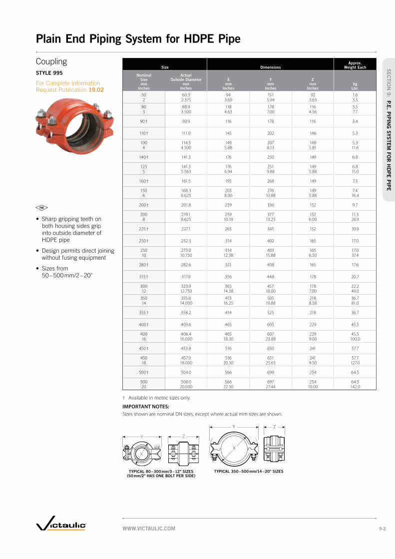
Size DimensionsApprox.
Weight Each
Nominal Size mm
Inches
Actual Outside Diameter
mm Inches
X mm
Inches
Y mm
Inches
Z mm
Incheskg
Lbs.
50 60.3 94 151 92 1.62 2.375 3.69 5.94 3.63 3.5
80 88.9 118 178 116 3.53 3.500 4.63 7.00 4.56 7.7
90 † 90.9 116 178 116 3.4
110 † 111.0 145 202 146 5.3
100 114.3 149 207 148 5.34 4.500 5.88 8.13 5.81 11.6
140 † 141.3 176 250 149 6.8
125 141.3 176 251 149 6.85 5.563 6.94 9.88 5.88 15.0
160 † 161.5 195 268 149 7.3
150 168.3 203 276 149 7.46 6.625 8.00 10.88 5.88 16.4
200 † 201.8 259 336 152 9.7
200 219.1 259 377 152 11.38 8.625 10.19 13.25 6.00 24.9
225 † 227.1 265 345 152 10.9
250 † 252.3 314 402 165 17.0
250 273.0 314 403 165 17.010 10.750 12.38 15.88 6.50 37.4
280 † 282.6 321 408 165 17.6
315 † 317.9 356 448 178 20.7
300 323.9 365 457 178 22.212 12.750 14.38 18.00 7.00 49.0
350 355.6 413 505 218 36.714 14.000 16.25 19.88 8.58 81.0
355 † 358.2 414 525 218 36.7
400 † 403.6 465 605 229 45.5
400 406.4 465 607 229 45.516 16.000 18.30 23.88 9.00 100.0
450 † 453.8 516 650 241 57.7
450 457.0 516 651 241 57.718 18.000 20.30 25.63 9.50 127.0
500 † 504.0 566 699 254 64.5
500 508.0 566 697 254 64.520 20.000 22.30 27.44 10.00 142.0
† Available in metric sizes only.
IMPORTANT NOTES:
Sizes shown are nominal DN sizes, except where actual mm sizes are shown.
Y Z
X
Y Z
X
Coupling
STYLE 995
19.02
TYPICAL 80 – 300 mm/3 – 12" SIZES (50 mm/2" HAS ONE BOLT PER SIDE)
TYPICAL 350 – 500 mm/14 – 20" SIZES
WWW.VICTAULIC.COM 9-2
Plain End Piping System for HDPE Pipe
SEC
TIO
N 9
: P.E
. PIP
ING
SYSTEM
FO
R H
DPE
PIP
E

Size DimensionsApprox.
Weight Each
Nominal Size mm
Inches
Actual Outside Diameter
mm Inches
X mm
Inches
Y mm
Inches
Z mm
Incheskg
Lbs.
50 60.3 84 133 71 1.42 2.375 3.31 5.22 2.78 3.0
80 88.9 111 178 81 3.03 3.500 4.38 6.99 3.20 6.6
100 114.3 144 210 99 4.04 4.500 5.68 8.25 3.90 8.7
125 141.3 172 248 101 5.25 5.563 6.75 9.77 3.97 11.5
150 168.3 199 286 102 6.76 6.625 7.84 11.25 4.00 14.8
200 219.1 259 355 106 9.88 8.625 10.18 13.96 4.16 21.7
250 273.0 321 427 116 15.610 10.750 12.63 16.81 4.56 34.3
300 323.9 370 477 123 17.012 12.750 14.58 18.76 4.85 37.5
IMPORTANT NOTES:
Sizes shown are nominal DN sizes, except where actual mm sizes are shown.
GroovedSide
Plain End HDPE Side
Y
X
ZY Z
X
STYLE 997
19.03
TYPICAL 50 mm/2" SIZE TYPICAL 80 – 300 mm/3 – 12" SIZES
EXAGGERATED FOR CLARITY
WWW.VICTAULIC.COM9-3
Plain End Piping System for HDPE Pipe
SEC
TIO
N 9
: P
.E.
PIP
ING
SYSTEM
FO
R H
DPE
PIP
E

SizeSealing
Surface* DimensionsApprox.
Weight Each
Nominal Size mm
Inches
Actual Outside Diameter
mm Inches
A Minimum
mm Inches
B Maximum
mm Inches
X mm
Inches
Z mm
Incheskg
Lbs.
100 114.3 114 147 229 86 5.74 4.500 4.50 5.78 9.00 3.38 12.5
150 168.3 168 202 279 102 7.86 6.625 6.63 7.97 11.00 4.00 17.3
200 219.1 220 254 343 114 14.08 8.625 8.63 10.00 13.50 4.50 30.8
* Minimum/maximum sealing surface on mating flange must be available for proper gasket seating. Entire area must be flat. Heavy serrated (phonograph record) finishes are not acceptable. When used with rubber seated wafer butterfly valves, a flat metal adapter plate is needed.
IMPORTANT NOTES:
Sizes shown are nominal DN sizes, except where actual mm sizes are shown.
A
B
X
Z
STYLE 994
19.04
TYPICAL FOR ALL SIZES
Orange area of mating face must be free from gouges, undulations
or deformities of any type for effective sealing.
WWW.VICTAULIC.COM 9-4
Plain End Piping System for HDPE Pipe
SEC
TIO
N 9
: P.E
. PIP
ING
SYSTEM
FO
R H
DPE
PIP
E
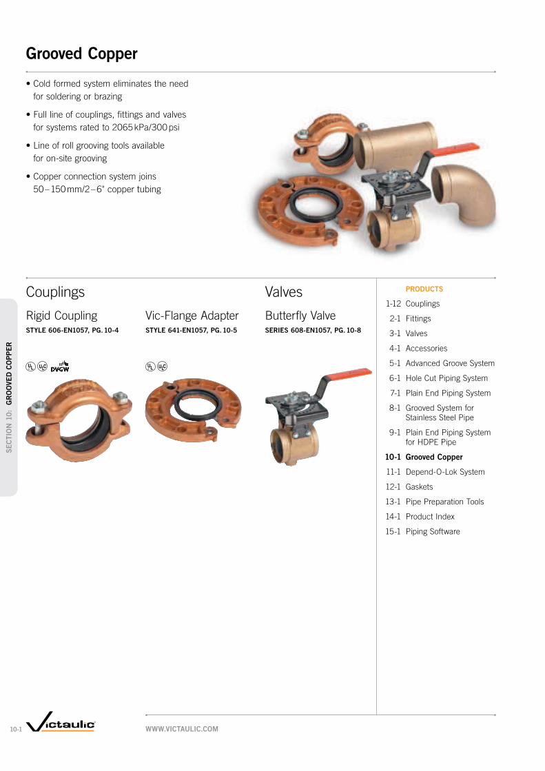
Butterfly ValveSERIES 608-EN1057, PG. 10-8
Valves PRODUCTS
1-12 Couplings
2-1 Fittings
3-1 Valves
4-1 Accessories
5-1 Advanced Groove System
6-1 Hole Cut Piping System
7-1 Plain End Piping System
8-1 Grooved System for
Stainless Steel Pipe
9-1 Plain End Piping System
for HDPE Pipe
10-1 Grooved Copper
11-1 Depend-O-Lok System
12-1 Gaskets
13-1 Pipe Preparation Tools
14-1 Product Index
15-1 Piping Software
for soldering or brazing
for systems rated to 2065 kPa/300 psi
for on-site grooving
50 – 150 mm/2 – 6" copper tubing
Rigid CouplingSTYLE 606-EN1057, PG. 10-4
Vic-Flange AdapterSTYLE 641-EN1057, PG. 10-5
Couplings
WWW.VICTAULIC.COM10-1
Grooved Copper
SEC
TIO
N 1
0:
GR
OO
VED
CO
PPER

Fittings
90° Elbow
NO. 610-EN1057, PG. 10-6
45° Elbow
NO. 611-EN1057, PG. 10-6
Tee
NO. 620-EN1057, PG. 10-6
Reducing Tee Grv. × Grv. × Grv.
NO. 625-EN1057, PG. 10-7
Reducing Tee Grv. × Grv. × Cup
NO. 626-EN1057, PG. 10-7
Concentric Reducer Grv. × Grv.
NO. 650-EN1057, PG.10-7
Concentric Reducer Grv. × Cup
NO. 652-EN1057, PG. 10-7
Cap
NO. 660-EN1057, PG. 10-6 NO. 660B-EN1057, PG. 10-6
Style 47 Clearflow Dielectric Waterway Fittings
Style 47 Clearflow dielectric waterway fittings provide a simple and effective
For details see page 4-10 or request publication 09.07.
WWW.VICTAULIC.COM 10-2
Grooved Copper
SEC
TIO
N 1
0: G
RO
OVED
CO
PPER

Size Wall ThicknessMax. Work Pressure*
Max. End Load
mm Inches
mm Inches
kPa psi
N Lbs.
54.0 1.2 1600 36642.125 0.05 232 824
54.0 2.0 2100 48092.125 0.08 305 1,081
64.0 2.0 1600 51472.250 0.08 232 1,157
66.7 1.2 1500 52412.625 0.05 220 1,178
66.7 2.0 2100 73382.625 0.08 305 1,650
76.1 1.5 1600 72773.000 0.06 232 1,636
76.1 2.0 1900 86423.000 0.08 275 1,943
88.9 2.0 1600 99313.500 0.08 232 2,232
108.0 1.5 1600 146574.250 0.06 232 3,295
108.0 2.5 1800 164904.250 0.10 260 3,707
133.0 1.5 1500 208395.236 0.06 220 4,685
133.0 3.0 1600 222295.236 0.12 232 4,997
159.0 2.0* 1500 297836.260 0.08 220 6,695
159.0 3.0 1500 297836.260 0.12 220 5,803
* When combined with older No. 610 and No. 611 elbows size 159.0 mm/6.260", made of wrought material, the maximum joint working pressure rating for Style 606 couplings is reduced to 1000 kPa/145 psi. Cast elbows size 159.0 mm/6.260" are rated to 1500 kPa/220 psi. Note that these older products may still be in stock with Victaulic and its distributors.
IMPORTANT NOTES:
Working Pressure and End Load are total, from all internal and external loads, based on the indicated type of copper tubing, standard roll grooved in accordance with Victaulic specifications.
For one time field test only, the Max. Working Pressure may be increased to 1½ times the figures shown.
WARNING: Depressurize and drain the piping system before attempting to install, remove, or adjust any Victaulic piping products.
Sizes shown are nominal DN sizes, except where actual mm sizes are shown.
Performance
tested on copper tubing.
Victaulic products are routinely
tested to failure in unrestrained
Using our normal minimum
provided regular verification of
indicated types of tubing.
WWW.VICTAULIC.COM10-3
SEC
TIO
N 1
0:
GR
OO
VED
CO
PPER
Grooved Copper – Couplings

SizeAllow Pipe End Sep. # Dimensions
Approx. Weight Each
Actual Size mm
Inches mm
Inches
X mm
Inches
Y mm
Inches
Z mm
Incheskg
Lbs.
54.0 0.76 81 118 46 0.72.125 0.03 3.17 4.63 1.80 1.54
64.0 0.76 89 129 46 0.92.250 0.03 3.50 5.08 1.80 1.98
66.7 0.76 93 130 46 0.92.625 0.03 3.67 5.13 1.80 1.98
76.1 0.76 103 152 46 1.13.000 0.03 4.05 5.97 1.80 2.42
88.9 0.76 116 162 46 1.43.500 0.03 4.57 6.38 1.80 3.1
108.0 4.30 138 181 49 1.74.250 0.17 5.44 7.14 1.94 3.75
133.0 4.60 165 229 50 2.55.236 0.18 6.50 9.01 1.97 5.51
159.0 4.60 191 255 49 2.96.260 0.18 7.53 10.02 1.94 6.39
# For field installation only. Style 606-EN1057 is essentially rigid and does not permit expansion/contraction.
IMPORTANT NOTES:
Sizes shown are nominal DN sizes, except where actual mm sizes are shown.
X
Y Z
Rigid Coupling
STYLE 606-EN1057
For Complete Information Request Publication 22.11
TYPICAL FOR ALL SIZES
or soldering
2065 kPa/300 psi
2 – 6" to fit copper tubing
WWW.VICTAULIC.COM 10-4
SEC
TIO
N 1
0: G
RO
OVED
CO
PPER
Grooved Copper – Couplings

Size Sealing Surface DimensionsApprox.
Weight Each
Actual mm
Nominal Inches
A Maximum
mm Inches
B Minimum
mm Inches
W mm
Inches
X mm
Inches
Y mm
Inches
Z mm
Inches kg
Lbs.
54.0 54 78 175 152 125 20 1.72.125 2.13 3.07 6.89 6.00 4.92 0.78 3.75
64.0 64 89 214 185 145 22 2.12.250 2.25 3.50 8.43 7.28 5.71 0.88 4.63
66.7 67 92 200 178 145 22 2.12.625 2.64 3.62 7.87 7.00 5.71 0.88 4.63
76.1 76 101 208 185 145 20 2.53.000 2.99 3.98 8.19 7.28 5.71 0.78 5.51
76.1 76 101 215 200 160 22 2.53.000 2.99 3.98 8.48 7.87 6.30 0.88 5.51
88.9 89 114 220 200 160 22 2.83.500 3.50 4.49 8.66 7.87 6.30 0.88 6.20
108.0 108 133 243 220 180 24 3.14.250 4.25 5.24 9.57 8.66 7.09 0.94 6.84
133.0 133 160 274 249 210 25 3.95.236 5.24 6.30 10.78 9.84 8.27 1.00 8.60
159.0 159 186 307 285 240 26 4.56.260 6.26 7.32 12.09 11.22 9.45 1.02 9.92
IMPORTANT NOTES:
Style 641-EN1057 Vic-Flange adapters for copper tubing provide rigid joints when used on copper tubing that is roll grooved to Victaulic dimensions and consequently allow no linear or angular movement at the joint.
For restrictions on where and how Vic-Flange adapters and flange washers can be used, refer to Publication 22.11.
Sizes shown are nominal DN sizes, except where actual mm sizes are shown.
B
A
Z
Y WX
flanged components to
grooved copper tubing
54.0 – 159.0 mm/2 – 6"
to fit copper tubing
Vic-Flange Adapter
STYLE 641-EN1057
For Complete Information Request Publication 22.11
TYPICAL FOR ALL SIZES
Orange area of mating face must be free from gouges, undulations
or deformities of any type for effective sealing.
WWW.VICTAULIC.COM10-5
SEC
TIO
N 1
0:
GR
OO
VED
CO
PPER
Grooved Copper – Couplings

SizeNo. 610-EN1057
90° ElbowNo. 611-EN1057
45° ElbowNo. 620-EN1057
TeeNo. 660-EN1057
Cap
Actual Size mm
Inches
C to E mm
Inches
Approx. Weight Each
kg Lbs.
C to E mm
Inches
Approx. Weight Each
kg Lbs.
C to E mm
Inches
Approx. Weight Each
kg Lbs.
T mm
Inches
Approx. Weight Each
kg Lbs.
54.0 74.0 0.4 56.0 0.4 68.0 0.5 c 24 0.5 c2.125 2.91 0.9 2.19 0.9 2.69 1.1 0.96 1.0
64.0 84.0 0.6 59.0 0.5 81.0 0.8 c + +2.250 3.31 1.3 2.31 1.1 3.20 1.8
66.7 84.0 0.6 c 59.0 0.5 81.0 0.8 c 24 0.6 c2.625 3.31 1.3 2.31 1.1 3.20 1.8 0.96 1.3
76.1 96.8 1.0 c 66.0 0.7 89.3 1.5 c + +3.000 3.81 2.1 2.59 1.6 3.52 3.3
88.9 109.0 1.7 c + + 90.0 1.5 24 0.6 c3.500 4.29 3.7 3.54 3.3 0.96 1.3
108.0 121.0 1.8 c 81.0 1.5 c 108.0 2.8 c 24.4 1.14.250 4.75 4.0 3.19 3.4 4.25 6.1 0.96 2.4
133.0 151.0 6.4 c + + 151.0 10.0 c + +5.236 5.94 14.0 5.94 22.1
159.0 176.0 9.1 c 92.0 5.9 c 176.0 13.2 c + +6.260 6.94 20.1 3.63 13.0 6.94 29.1
c = Bronze casting; all others, drawn copper.
+ Contact Victaulic for details.
IMPORTANT NOTES:
Designed for installation into copper systems using either a Style 606-EN1057 coupling or Style 641-EN1057 Vic-Flange adapter.
Sizes shown are nominal DN sizes, except where actual mm sizes are shown.
SizeNo. 660B-EN1057
Cap
Actual Size mm
Inches
Approx. Weight Each
kg Lbs.
54.0 × 25.4 0.32.125 1 0.7
64.0 × 25.4 0.32.250 1 0.7
76.1 × 25.4 0.33.000 1 0.7
88.9 × 25.4 0.63.500 1 1.3
88.9 × 50.8 +3.500 2
+ Contact Victaulic for details.
IMPORTANT NOTES:
Designed for installation into copper systems using either a Style 606-EN1057 coupling or Style 641-EN1057 Vic-Flange adapter.
Sizes shown are nominal DN sizes, except where actual mm sizes are shown.
C to E
Cto E
C to E
C to E
CtoE
T
T
NO. 610-EN1057 90° Elbow
NO. 611-EN1057 45° Elbow
NO. 620-EN1057 Tee
NO. 660-EN1057 Cap
For Complete Information Request Publication 22.11
NO. 610-EN1057 NO. 611-EN1057 NO. 620-EN1057 NO. 660-EN1057
NO. 660B-EN1057 Cap
For Complete Information Request Publication 22.11
NO. 660B-EN1057
WWW.VICTAULIC.COM 10-6
SEC
TIO
N 1
0: G
RO
OVED
CO
PPER
Grooved Copper – Fittings

SizeNo. 625-EN1057 Grv. × Grv. × Grv.
No. 626-EN1057 Grv. × Grv. × Cup
Actual Outside Dia.
mm Inches
C to E mm
Inches
C to B mm
Inches
Approx. Wgt. kg
Lbs.
C to E mm
Inches
C to B mm
Inches
Cup mm
Inches
Approx. Wgt. kg
Lbs.
54.0 × 54.0 × 35.0 — — — 125 78 25 0.62.125 2.125 1.378 4.92 3.07 0.98 1.3
42.0 — — — 125 78 29 0.41.654 4.92 3.07 1.14 0.9
67.0 × 67.0 × 35.0 — — — 125 85 25 0.82.626 2.626 1.378 4.92 3.35 0.98 1.8
42.0 — — — 125 85 29 0.61.654 4.92 3.35 1.14 1.3
54.0 83 86 0.7 c — — — —2.125 3.27 3.39 1.5
76.1 × 76.1 × 35.0 — — — 125 89 25 0.93.000 3.000 1.378 4.92 3.50 0.98 2.0
42.0 — — — 125 89 29 0.91.654 4.92 3.50 1.14 2.0
54.0 76 86 1.0 c — — — —2.125 2.99 3.39 2.2
66.7 83 89 1.1 c — — — —2.626 3.27 3.50 2.4
108.0 × 108.0 × 35.0 — — — 150 105 25 1.54.252 4.252 1.378 5.91 4.13 0.98 3.3
42.0 — — — 103 100 42 1.61.654 4.06 3.94 1.65 3.5
66.7 100 103 2.6 c — — — —2.626 3.94 4.06 5.7
76.1 106 106 4.6 c — — — —3.000 4.17 4.17 10.1
133.0 × 133.0 × 35.0 — — — 99 96 25 1.95.236 5.236 1.378 3.90 3.78 0.98 4.2
42.0 — — — 103 100 42 2.21.654 4.06 3.94 1.65 4.9
54.0 + + + — — — —2.125
67.0 + + + — — — —2.626
76.1 + + + — — — —3.000
108.0 + + + — — — —4.252
159.0 × 159.0 × 35.0 — — — 99 109 25 2.26.260 6.260 1.378 3.90 4.29 0.98 4.9
42.0 — — — 103 113 29 2.31.654 4.06 4.45 1.14 5.1
54.0 + + + — — — —2.125
66.7 + + + — — — —2.626
76.1 + + + — — — —3.000
108.0 106 130 4.4 c — — — —4.252 4.17 5.12 9.7
133.0 119 132 5.1 — — — —5.236 4.69 5.20 11.2
c = Bronze casting; all others, drawn copper.
+ Contact Victaulic for details.
IMPORTANT NOTES:
Sizes shown are nominal DN sizes, except where actual mm sizes are shown.
SizeNo. 650-EN1057 & No. 652-EN1057
Grv. × Grv. & Grv. × Cup
Actual Outside Dia.
mm Inches
E to E mm
Inches
Cup mm
Inches
Approx. Wgt. Each
kg Lbs.
54.0 × 35.0* + + +2.125 137.8
42.0* 75 + 0.21.654 2.95 0.4
64.0 × 54.0 + — +2.250 2.125
66.7 × 35.0* + + +2.626 1.378
42.0* 88 + 0.31.654 3.46 0.7
54.0 83 86 0.72.125 3.27 3.39 1.5
76.1 × 54.0 64 — 0.4 c3.000 2.125 2.52 0.9
64.0 64 — 0.5 c2.250 2.52 1.0
66.7 64 — 0.5 c2.626 2.52 1.0
88.9 × 54.0 76 — 0.9 c3.500 2.125 2.99 2.0
64.0 + — +2.250
76.1 76 — 0.9 c3.000 2.99 2.0
108.0 × 54.0 + — +4.252 2.125
64.0 + — +2.250
66.7 76 — 0.9 c2.626 2.99 2.0
76.1 76 — 0.9 c3.000 2.99 2.0
88.9 76 — + c3.500 2.99
133.0 × 76.1 + — +3.000
108.0 + — +4.252
159.0 × 54.0 + — +6.260 2.125
66.7 + — +2.626
76.1 + — +3.000
108.0 + — +4.252
133.0 + — +5.236
* No. 652-EN1057; Cup connection
c = Bronze casting; all others, drawn copper.
+ Contact Victaulic for details.
IMPORTANT NOTES:
Sizes shown are nominal DN sizes, except where actual mm sizes are shown.
C to E
CtoB
E to E E to E
Cup
NO. 625-EN1057 Grv. × Grv. × Grv.
NO. 626-EN1057 Grv. × Grv. × Cup
For Complete Information Request Publication 22.11
NO. 625-EN1057
C to E
Cup
CtoB
NO. 626-EN1057
NO. 650-EN1057 Grv. × Grv.
NO. 652-EN1057 Grv. × Cup
For Complete Information Request Publication 22.11
NO. 650-EN1057 NO. 652-EN1057
WWW.VICTAULIC.COM10-7
SEC
TIO
N 1
0:
GR
OO
VED
CO
PPER
Grooved Copper – Fittings

Size DimensionsApprox.
Wgt. Each Flow Coefficient@ (Fully Open)
KV Values
C V Values
Actual Size mm
Inches
A End to End
mm Inches
B Height
mm Inches
C mm
Inches
D mm
Inches
E mm
Inches
F mm
Inches
G mm
Inches
H mm
Inches
w/o Oper.
kg Lbs.
66.7 96 121 42.93 75.18 — 63.5 55.1 59 1.9 281.12.625 3.77 4.77 1.69 2.96 2.5 2.17 2.31 4.1 325
76.1 96 137 50.80 83.1 2 76.2 63.0 59 2.2 415.23.000 3.77 5.39 2.00 3.27 0.08 3.00 2.48 2.31 4.8 480
@ KV/C
V values for flow of water at +16°C/+60°F with a fully open valve.
IMPORTANT NOTES:
All Series 608-EN1057 butterfly valves are bronze castings.
Sizes shown are nominal DN sizes, except where actual mm sizes are shown.
C
DB
G
E
F
HA
Butterfly Valve
SERIES 608-EN1057
For Complete Information Request Publication 22.11
to full working pressure
2065 kPa/300 psi
TYPICAL FOR ALL SIZES
WWW.VICTAULIC.COM 10-8
SEC
TIO
N 1
0: G
RO
OVED
CO
PPER
Grooved Copper – Valves

Depend-O-Lok Couplings
The Depend-O-Lok system represents a new generation
of technologically advanced couplings.
The design of Depend-O-Lok couplings allows for
out-of-round pipe – making it easier to install than
competitive joining methods. Couplings can be designed
to meet almost any application or service criteria and
provides a reliable, economical alternative to traditional
bolted sleeve-type couplings.
For Complete Information Request Publication PB-257
(F × E) Bolted Split-Sleeve Expansion Couplings
Pipe joints that provide for thermal expansion
and contraction
Coupling Components and Benefits
CLOSURE PLATES
Simplify installation by enabling the coupling to seal with
fewer bolts (than ordinary sleeve type couplings), and
to pull pipes into alignment. This also allows the coupling
to be provided in multiple segments, when needed,
for ease of handling or installation on existing pipe.
SPLIT-SLEEVE (BODY)
Designed for both high and low pressure applications
and maximum pipe protection on “out of round” pipe.
The “double arch” shape of the sleeve provides high section
modulus and strengthens the pipe joint. Coupling installation
is accomplished without the need for jacks, wedges, or
sledge hammers. Harness lugs, if required, can be shorter.
O-RINGS
Proven effective during more than 80 years of use.
SEALING PLATE/PAD
Ensures leak-tight seal on joints.
BOLTS AND NUTS
Sized to provide yield strength greater than the hoop
strength of the coupling body, and utilize flat washers.
Stainless steel or hot dipped galvanized bolts are available.
RESTRAINT RINGS (PROVIDED)
Must be welded to pipe ends providing the means by which
the D-O-L coupling restrains the pipe within the coupling.
SHOULDERS
The shoulders close over the pipe on the outside
of the restraint rings to provide end load resistance.
(E × E) Bolted Split-Sleeve Flexible Coupling
Unrestrained, flexible bottle-tight joints
(F × F) Bolted Split-Sleeve Restrained Flexible Coupling
Fully restrained pipe joints without external harnessing
1
2
3
4
5
6
7
E × E Request Publication 60.10 F × F Request Publication 60.11 F × E Request Publication 60.12
7 5 2
45136
7 5 2
45136
7 5 2
4513
SEC
TIO
N 1
1:
DEPEN
D-O
-LO
K S
YSTEM
Depend-O-Lok System
WWW.VICTAULIC.COM11-1

FluidMaster/
AirMaster
Expansion
Joint
restrained joints for air and
fluid-conveying pipelines
that are designed to
operate at design
pressures of the system
expansion joints
accommodating thermal
expansion and contraction
of pipelines
OmniFlex Stainless
Steel Bellows-Type
Expansion Joints
Can also accommodate
lateral movement
Depend-O-Lok
Bolted Split-Sleeve
Expansion Couplings
Accommodates expansion/
contraction up to
165.1 mm/6 ½"
Paragon Expansion Joints
Fabricated mechanical
expansion joints
PolyMax
Fabricated steel mechanical
slip-type expansion joints
Depend-O-Lok couplings are made to meet the
individual needs of piping projects. With this ability
to customize the coupling to the project specifications
Depend-O-Lok products are used on a wide variety
of systems.
One of the more unusual applications for the
Depend-O-Lok couplings was a fish bypass line
that was installed to help salmon avoid a river dam
in their annual migration. Depend-O-Lok couplings
allowed for the expansion and contraction needed
for this type of system while also reducing installation
time and costs.
SEC
TIO
N 1
1: D
EPEN
D-O
-LO
K S
YSTEM
Depend-O-Lok System
WWW.VICTAULIC.COM 11-2

Grooved Copper
Tubing with
FlushSeal Gasket
Standard
Victaulic gaskets are designed to provide life-of-the-system
service in a wide variety of applications. Gasket materials
are available to meet most piping applications. For a list
of service recommendations by gasket type see pg. 12-5.
For Complete Information request publication 05.01.
Outlet
Reducing Vic-Flange
FlushSeal
Mechanical-T
Plain End
EndSeal
Plain End Piping
System for
HDPE Pipe
Gasket StylesILLUSTRATIONS EXAGGERATED FOR CLARITY
Advanced Groove
System (AGS)
WWW.VICTAULIC.COM12-1
Gaskets
SEC
TIO
N 1
2:
GA
SK
ETS

PRODUCTS
1-12 Couplings
2-1 Fittings
3-1 Valves
4-1 Accessories
5-1 Advanced Groove System
6-1 Hole Cut Piping System
7-1 Plain End Piping System
8-1 Grooved System for
Stainless Steel Pipe
9-1 Plain End Piping System
for HDPE Pipe
10-1 Grooved Copper
11-1 Depend-O-Lok System
12-1 Gaskets
13-1 Pipe Preparation Tools
14-1 Product Index
15-1 Piping Software
Gasket/O-ring Data
To assure the maximum life for the service intended, proper gasket selection
and specification in ordering is essential. Many factors must be considered
in determining the optimum gasket/o-ring for a specific service. The foremost
consideration is temperature, along with concentration of product, duration
of service and continuity of service. Temperatures beyond the recommended
limits have a degrading effect on the polymer. Therefore, there is a direct
relationship between temperature, continuity of service and gasket life.
Services listed are General Service Recommendations only. It should be noted
that there are services for which these gaskets/o-rings are not recommended.
Reference should always be made to the latest Victaulic Gasket Selection Guide
(publication 05.01) for specific service recommendations and for a listing
of services which are not recommended.
Gasket recommendations apply only to Victaulic gaskets and o-rings.
Recommendations for a particular service do not necessarily imply compatibility
of the coupling housing, related fittings or other components for the same service.
These recommendations do not apply to rubber-lined or rubber seal valves
or other rubber-lined products. Refer to Valve Materials Selection in Section
08.02 or contact Victaulic for recommendations.
Victaulic gaskets are clearly marked as part of the mold with the gasket size,
style and compound for easy identification.
Gasket Materials
When Victaulic couplings were first developed, natural rubber compounds were
used. As elastomer technology advanced, superior gasket materials became available
and were added to the Victaulic line. This allows Victaulic to presently offer a variety
of synthetic rubber gaskets to provide the option of selecting Victaulic products for
the widest variety of applications. For most water applications the Victaulic Grade
“E” EPDM (ethylene propylene diene monomer) gasket compound is recommended.
Victaulic Grade “E” material has premium performance properties with respect to
aging and resistance to heat and hot water. Heat aging tests at +121°C/+250°F
conducted on this material show essentially no change in physical properties.
This situation is further enhanced when this rubber is subjected to an essentially
non-oxidative environment such as a gasket in a water piping system. For example,
aging tests in a nonoxidative atmosphere show essentially no change in physical
properties of this material even when tested at temperatures up to +177°C/+350°F.
Since water has no deteriorating effect on the elastomer, temperature is the only
limiting factor to be considered in determining the life expectancy of the elastomer
in water service. The superior performance of the Grade “E” elastomer permits its
use for hot water service up to +110°C/+230°F. The Grade “E” gasket is superior
to previous gasket materials by all performance barometers, including high and
low temperature limits, tensile strength, chemical resistance and shelf life.
WWW.VICTAULIC.COM 12-2
Gaskets
SEC
TIO
N 1
2: G
ASK
ETS

Gasket Performance The sealing efficiency of Victaulic gaskets is such that the gasket forms an initial seal
as it is stretched over the pipe ends. Upon placement of the housing around the gasket
and into the grooves, the gasket is positioned. As the housing segments are tightened,
the resilient elastomeric gasket conforms to the internal cavity of the housing and is
further compressed, enhancing the gasket’s seal against the pipe. The Victaulic gasket
is pressure responsive.
The combination of these characteristics creates a permanent, leak-tight triple seal
on a variety of piping materials including carbon steel, stainless steel, aluminum,
PVC and copper. Line pressure serves to strengthen the seal through the combination
of normal gasket resilience, housing reinforcement and the action of pressure
downward on the lips.
Vacuum Service – The Victaulic gasket design seals equally well under pressure or
vacuum. Vacuum creates a pressure differential between the inside and outside of the
piping system. The resulting increased force from the external pressure has the same seal
enhancement effect as internal pressure. For continuous vacuum service greater than
254 mm/10" of mercury, we recommend the use of molded Victaulic FlushSeal gaskets
or Victaulic standard gaskets with a metal ring liner, both available from your Victaulic
distributor. The FlushSeal feature and the metal liner both prevent distortion of the
gasket due to the pulling action of a high vacuum at the center of the gasket.
Either molded FlushSeal gaskets or gaskets with metal liners are recommended on
strong vacuums and are suitable for applications wherein vacuum conditions are
anticipated to a maximum value of 760 mm/29.9" of mercury.
ANSI/NSF 61 and Australia Watermark Standards – ANSI/NSF 61 and Australia
Watermark are National Standards that were developed to establish minimum
requirements for the control of potential adverse human health effects from products
which contact drinking water. Their primary focus is on contaminants or impurities which
may be imparted indirectly to drinking water. Materials that do not come in direct
contact with the potable water do not require evaluation. The classification categories
for pipe and related products and joining and sealing materials, as established by
ANSI/NSF 61/Australia Watermark are “cold”, which is limited to +30°C/+86°F maximum
and “hot” which is limited to +82°C/+180°F maximum. These categories were established
by the maximum ambient distribution temperature of unheated water for “cold” and a
temperature well in excess of a scalding temperature for “hot” domestic water.
The following list represents the current classifications on our products:
EPDM “E” Gaskets: UL classified in accordance with ANSI/NSF 61/Australia Watermark
for cold +30°C/+86°F and hot +82°C/+180°F potable water service.
Halogenated Butyl “M” Gaskets: UL classified in accordance with ANSI/NSF 61/
Australia Watermark for cold +30°C/+86°F potable water service.
PPS Coating: The PPS (Polyphenylene Sulfide blend) coating applied to our
Vic-300 AGS butterfly valves is UL classified in accordance with ANSI/NSF 61/Australia
Watermark for cold +30°C/+180°F and hot +82°C/+180°F potable water service.
UNIQUE C-SHAPED GASKET FORMS A TRIPLE SEAL
SEALS BETWEEN THE PIPE ENDS AND THE GROOVE
SURROUNDED, REINFORCED AND SLIGHTLY COMPRESSED BY THE HOUSING
SEAL IS ENHANCED BY PRESSURE OR VACUUM IN THE LINE
WWW.VICTAULIC.COM12-3
Gaskets
SEC
TIO
N 1
2:
GA
SK
ETS
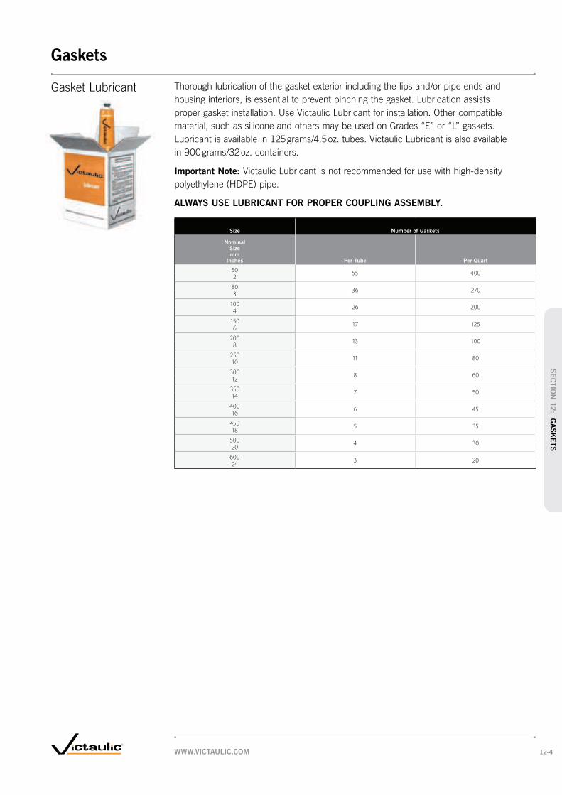
Size Number of Gaskets
Nominal Size mm
Inches Per Tube Per Quart
50 55 4002
80 36 2703
100 26 2004
150 17 1256
200 13 1008
250 11 8010
300 8 6012
350 7 5014
400 6 4516
450 5 3518
500 4 3020
600 3 2024
Gasket Lubricant Thorough lubrication of the gasket exterior including the lips and/or pipe ends and
housing interiors, is essential to prevent pinching the gasket. Lubrication assists
proper gasket installation. Use Victaulic Lubricant for installation. Other compatible
material, such as silicone and others may be used on Grades “E” or “L” gaskets.
Lubricant is available in 125 grams/4.5 oz. tubes. Victaulic Lubricant is also available
in 900 grams/32 oz. containers.
Important Note: Victaulic Lubricant is not recommended for use with high-density
polyethylene (HDPE) pipe.
ALWAYS USE LUBRICANT FOR PROPER COUPLING ASSEMBLY.
WWW.VICTAULIC.COM 12-4
Gaskets
SEC
TIO
N 1
2: G
ASK
ETS
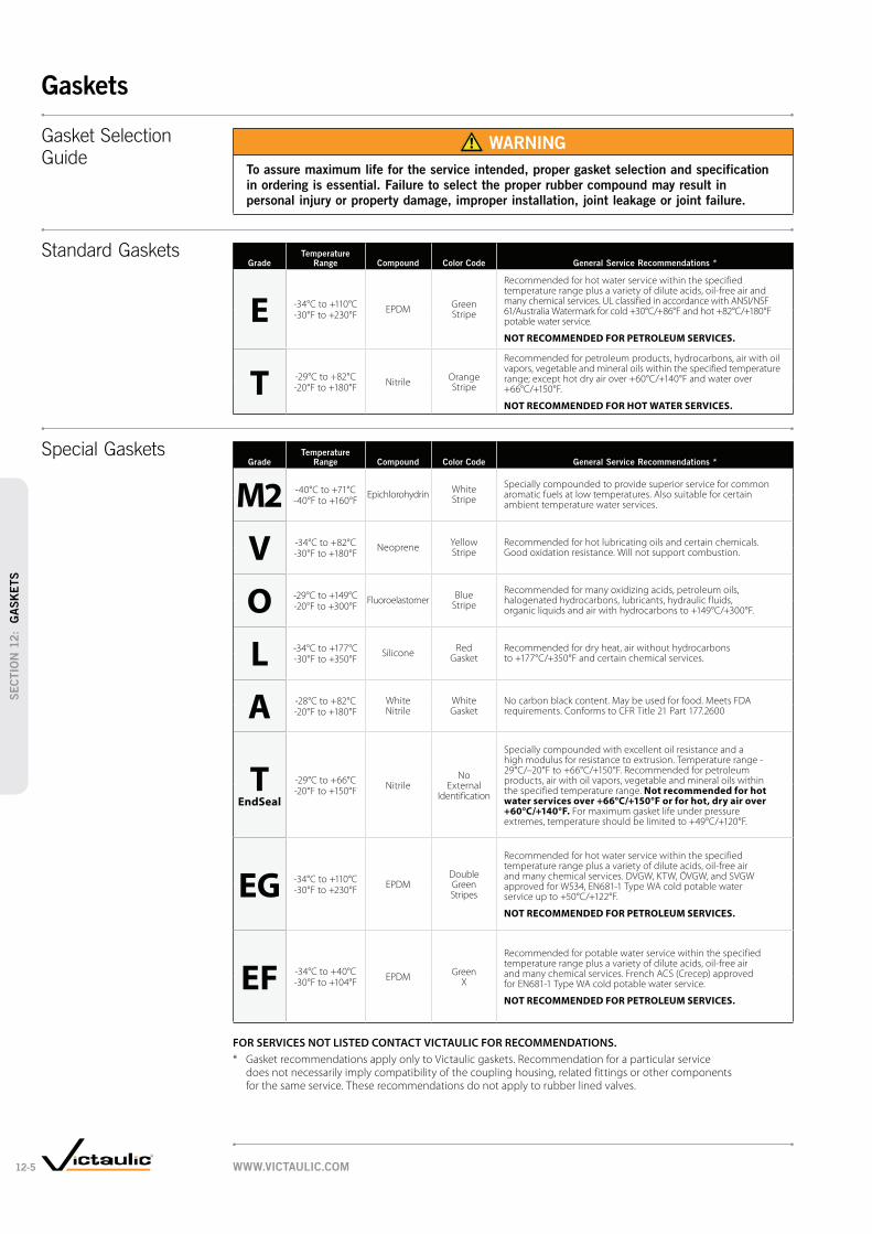
GradeTemperature
Range Compound Color Code General Service Recommendations *
E -34°C to +110°C EPDM Green Stripe
Recommended for hot water service within the specified temperature range plus a variety of dilute acids, oil-free air and many chemical services. UL classified in accordance with ANSI/NSF 61/Australia Watermark for cold +30°C/+86°F and hot +82°C/+180°F potable water service.
NOT RECOMMENDED FOR PETROLEUM SERVICES.
-30°F to +230°F
T -29°C to +82°CNitrile Orange
Stripe
Recommended for petroleum products, hydrocarbons, air with oil vapors, vegetable and mineral oils within the specified temperature range; except hot dry air over +60°C/+140°F and water over +66°C/+150°F.
NOT RECOMMENDED FOR HOT WATER SERVICES.
-20°F to +180°F
GradeTemperature
Range Compound Color Code General Service Recommendations *
M2 -40°C to +71°C Epichlorohydrin White Stripe
Specially compounded to provide superior service for common aromatic fuels at low temperatures. Also suitable for certain ambient temperature water services.-40°F to +160°F
V -34°C to +82°C Neoprene Yellow Stripe
Recommended for hot lubricating oils and certain chemicals. Good oxidation resistance. Will not support combustion.-30°F to +180°F
O -29°C to +149°C Fluoroelastomer Blue Stripe
Recommended for many oxidizing acids, petroleum oils, halogenated hydrocarbons, lubricants, hydraulic fluids, organic liquids and air with hydrocarbons to +149°C/+300°F.-20°F to +300°F
L -34°C to +177°C Silicone Red Gasket
Recommended for dry heat, air without hydrocarbons to +177°C/+350°F and certain chemical services.-30°F to +350°F
A -28°C to +82°C White Nitrile
White Gasket
No carbon black content. May be used for food. Meets FDA requirements. Conforms to CFR Title 21 Part 177.2600-20°F to +180°F
T EndSeal
-29°C to +66°CNitrile
No External
Identification
Specially compounded with excellent oil resistance and a high modulus for resistance to extrusion. Temperature range -29°C/–20°F to +66°C/+150°F. Recommended for petroleum products, air with oil vapors, vegetable and mineral oils within the specified temperature range. Not recommended for hot water services over +66°C/+150°F or for hot, dry air over +60°C/+140°F. For maximum gasket life under pressure extremes, temperature should be limited to +49°C/+120°F.
-20°F to +150°F
EG -34°C to +110°CEPDM
Double Green Stripes
Recommended for hot water service within the specified temperature range plus a variety of dilute acids, oil-free air and many chemical services. DVGW, KTW, ÖVGW, and SVGW approved for W534, EN681-1 Type WA cold potable water service up to +50°C/+122°F.
NOT RECOMMENDED FOR PETROLEUM SERVICES.
-30°F to +230°F
EF -34°C to +40°CEPDM Green
X
Recommended for potable water service within the specified temperature range plus a variety of dilute acids, oil-free air and many chemical services. French ACS (Crecep) approved for EN681-1 Type WA cold potable water service.
NOT RECOMMENDED FOR PETROLEUM SERVICES.
-30°F to +104°F
FOR SERVICES NOT LISTED CONTACT VICTAULIC FOR RECOMMENDATIONS.
* Gasket recommendations apply only to Victaulic gaskets. Recommendation for a particular service does not necessarily imply compatibility of the coupling housing, related fittings or other components for the same service. These recommendations do not apply to rubber lined valves.
Gasket Selection
Guide WARNING
To assure maximum life for the service intended, proper gasket selection and specification
in ordering is essential. Failure to select the proper rubber compound may result in
personal injury or property damage, improper installation, joint leakage or joint failure.
Standard Gaskets
Special Gaskets
WWW.VICTAULIC.COM12-5
Gaskets
SEC
TIO
N 1
2:
GA
SK
ETS

Rating Code Key
G Good
C Conditional (Submit analysis of materials to Victaulic for positive recommendations)
NR Not Recommended (See pg. 12-8 for complete listing)
FOR SERVICES NOT LISTED CONTACT VICTAULIC FOR RECOMMENDATIONS.
Gasket recommendations apply only to Victaulic gaskets. Recommendation for a particular service does not necessarily imply compatibility of the coupling housing, related fittings or other components for the same service. These recommendations do not apply to rubber lined valves.
Gasket Selection Chemical compositions are listed in alphabetical order. Unless otherwise noted,
temperatures are ambient. For chemicals or combinations not listed contact Victaulic
for recommendations. DO NOT ASSUME THAT A SERVICE SIMILAR TO THE ONE
LISTED CAN BE ACCOMMODATED WITH THE SAME GASKET.
The data and recommendations presented are based upon the best information
available resulting from our field experience and laboratory testing by our own
Engineering Department. In addition, we have incorporated the recommendations
supplied by prime producers of basic copolymer materials and information furnished
by leading molders of rubber products.
The information presented in this guide is general in scope and should be used only
with this full knowledge and understanding. In unusual, critical or severe services,
full information should be referred to Victaulic.
Where possible, materials should be subjected to simulated service conditions to determine
their suitability for the service intended. Furthermore, it should not be concluded that, in
instances where a gasket is not affected by several substances used alone, their combination
will have no reaction on the gasket. Caution should be exercised with explosive, inflammable
or toxic fluids. All gasket recommendations are based on pressure and temperature
limitations published by Victaulic. Borderline services always should be verified
by Victaulic.
Where two gaskets are shown under Gasket Grade, both are acceptable under
normal conditions for the service listed.
WWW.VICTAULIC.COM 12-6
Gaskets
SEC
TIO
N 1
2: G
ASK
ETS

Chemical Composition
Rating
Code
Gasket
Grade
ASTM #3 Oil G T
Acetaldehyde G E
Acetamide G T
Acetic Acid up to 10% 38°C/100°F G E
Acetic Acid up to 10-50% 38°C/100°F G L
Acetic Acid, Glacial 38°C/100°F G L
Acetic Anhydride G E
Acetone G E
Acetonitrile G T
Acetophenone G E
Acetylene C E/T
Acrylic Resin G V
Acrylonitrile NR —
Adipic Acid G T
Alkalis G E
Allyl Alcohol to 96% G E
Allyl Chloride NR —
Alum Sulfuric Acid C O
Alums G E/T
Aluminum Chloride G E/T
Aluminum Fluoride G E/T
Aluminum Hydroxide G E
Aluminum Nitrate G V/E/T
Aluminum Oxychloride C T
Aluminum Phosphate G E
Aluminum Salts G E
Aluminum Sulfate G E/T
Ammonia, Anhydrous (Pure Ammonia) NR —
Ammonia, Aqueous (40% Max) G E
Ammonium Alum G V
Ammonium Bifluoride G T
Ammonium Carbonate G E
Ammonium Chloride G T
Ammonium Fluoride G E
Ammonium Hydroxide G E
Ammonium Metaphosphate G E
Ammonium Nitrate G T
Ammonium Nitrite G E
Ammonium Persulfate, to 10% G E
Ammonium Phosphate G T
Ammonium Sulfamate G T
Ammonium Sulfate G E/T
Ammonium Sulfide G E
Ammonium Thiocyanate G E
Amyl Acetate G E
Amyl Acetate G E
Amyl Alcohol G E
Amyl Borate G V
Amyl Chloride NR —
Amyl Chloronaphthalene C T
Anderol G O
Anthraquinone NR —
Anthraquinone Sulfonic Acid NR —
Aniline G E
Aniline Dyes C E
Aniline Hydrochloride C E
Aniline Oil G E
Animal Fats G A
Antimony Chloride G E
Antimony Trichloride G E
Argon Gas G E/0
Aroclor(s) G O
Arsenic Acid, to 75% G T
Arylsulfonic Acid NR —
Barium Carbonate G E
Barium Chloride G E/T
Barium Hydroxide G E/T
Barium Nitrate G V
Barium Sulfide G T
Beer G A
Beet Sugar Liquors G A
Benzaldehyde C E
Benzene G O
Benzene Sulfonic (Aromatic Acid) C V
Benzine (see Petroleum Ether) G O
Benzoic Acid G E
Benzol G O
Chemical Composition
Rating
Code
Gasket
Grade
Benzyl Alcohol G E
Benzyl Benzoate G E
Black Sulfate Liquor G T
Blast Furnace Gas C T
Bleach, 12% Active Cl2 C E
Borax G E
Bordeaux Mixture G E
Boric Acid G E/T
Bromine G O
Bromine Water G V
Butadiene C V
Butane Gas C T
Butanol (see Butyl Alcohol) G E/T
Butter G A
Butyl Acetate C E
Butyl Acetyl Ricinoleate G E
Butyl Alcohol G E/T
Butyl “Cellosolve Adipate” G E/T
Butyl Phenol C E
Butyl Stearate G T
Butylene G T
Butylene Glycol G E
Butyne Diol NR —
Butyraldehyde C V
Cadmium Cyanide C V
Calcium Acetate C T
Calcium Bisulphate G T
Calcium Bisulphide G T
Calcium Bisulphite G T
Calcium Chloride G E/T
Calcium Fluophosphate C V
Calcium Hydroxide (Lime) G E/T
Calcium Hypochlorite G E
Calcium Hypochloride G E
Calcium Nitrate G V/E/T
Calcium Sulfate G E/T
Calcium Sulfide G E
Caliche Liquors G T
Cane Sugar Liquors G A
Carbitol G E/T
Carbonic Acid, Phenol G O
Carbon Bisulphide C O
Carbon Dioxide, Dry G E/T
Carbon Dioxide, Wet G E/T
Carbon Disulphide G O
Carbon Monoxide G E
Carbon Tetrachloride G O
Castor Oil G A
Caustic Potash G E
Cellosolve Acetate G E
Cellosolve (Alcohol Ether) G E
Cellulose Acetate G E
Cellulube 220 (Tri-Aryl-Phosphate) G E
Cellulube Hydraulic Fluids G E
China Wood Oil, Tung Oil G T
Chloralhydrate NR —
Chloric Acid to 20% C E
Chlorine, Dry C O
Chlorine, Water 4000 PPM (max.) C E
Chlorinated Parafine (Chlorocosane) G T
Chloroacetic Acid G E
Chloroacetone G E
Chlorobenzene C O
Chlorobromomethane NR —
Chloroform G O
Chlorosulphonic Acid NR —
Chrome Alum G T
Chrome Plating Solutions G O
Chromic Acid, to 25% G O
Citric Acid G E
Cocoanut Oil G A
Cod Liver Oil G A
Coke Oven Gas G T/O
Copper Chloride G T
Copper Cyanide G T
Copper Fluoride G E
Copper Nitrate G E/T
Copper Sulfate G E/T
Corn Oil G A
Chemical Composition
Rating
Code
Gasket
Grade
Cotton Seed Oil G A
Creosol, Cresylic Acid G O
Creosote, Coal Tar G O
Creosote, Wood G O
Cupric Fluoride G T
Cupric Sulfate G T
Cyclohexane (Alicyclic Hydrocarbon) G O
Cyclohexanol G V
Cyclohexanone C E
Deionized Water G E
Dextrim G T
Diacetone Alcohol G V
Dibutyl Phthalate G E
Dichloro Difloro Methane G T
Dicyclohexylamine C T
Diesel Oil G T
Diethyl Ether C T
Diethyl Sebacate G E
Diethylamine G T
Diethylene Glycol G E/T
Digester Gas G T/S
Dimethylamine G T
Dioctyl Phthalate G E
Dioxane G E
Dipentene (Terpene-Hydrocarbon) C T
Dipropylene Glycol G T
Dowtherm A G O
Dowtherm E G O
Dowtherm SR-1 G T/E
Ethanolamine G E
Ethyl Acetoacetate G E
Ethyl Acrylate G L
Ethyl Alcohol G E/T
Ethyl Cellulose C E
Ethyl “Cellusolve” G E
Ethyl Chloride G E
Ethyl Ether C T
Ethyl Formate C V
Ethyl Oxalate G E
Ethyl Silicate G T
Ethylene Chlorohydrin G E
Ethylene Diamine G T
Ethylene Dichloride (Dichloroethane) G O
Ethylene Glycol G E/T
Ethylene Oxide NR —
Fatty Acids G A
Ferric Chloride, to 35% G E/T
Ferric Chloride, Saturated G E
Ferric Hydroxide C E
Ferric Nitrate G V
Ferric Sulfate G T
Ferrus Ammonium Sulfate to 30% G V
Fish Oils G A
Fluboric Acid G E
Fluorine Gas, Wet NR —
Fluorosilicic Acid G V
Fly Ash G E
Foam G E
Fog Oil G T
Formaldehyde G E/T
Formanide G T
Formic Acid G E
Freon 11, 54°C/130°F G T
Freon 12, 54°C/130°F G T
Freon 21 NR —
Freon 22, 54°C/130°F G V
Freon 113 54°C/130°F G T
Freon 114, 54°C/130°F G T
Freon 123 NR —
Freon 134a, 80°C/176°F G E/T
Fructose G T
Fuel Oil G T
Fumaric Acid G E
Furan NR —
Furfuryl Alcohol G E
Gallic Acid NR —
Gasoline, Refined G T
Gasoline, Refined, Unleaded C O
Gelatin G A
Chemical Composition
Rating
Code
Gasket
Grade
Glucose G A
Glue G T/E
Glycerin G E/T
Glycerol G E/T
Glycol G E/T
Glycolic Acid C E
Grease G T
Green Sulfate Liquor G T
Halon 1301 G E
Heptane G T
Hexaldehyde G E
Hexane G T
Hexanol Tertiary G T
Hexyl Alcohol G V/T
Hexylene Glycol G T
Hydrobromic Acid, to 40% G E
Hydrochloric Acid, to 36%, 24°C/75°F G E
Hydrochloric Acid, to 36%, 70°C/158°F C O
Hydrocyanic Acid G E
Hydrofluoric Acid, to 75%, 24°C/75°F G O
Hydrofluosilicic Acid G T
Hydrogen Gas, Cold C E/T
Hydrogen Gas, Hot C E
Hydrogen Peroxide, to 50% C L
Hydrogen Peroxide, to 90% C O
Hydrogen Phosphide NR —
Hydrogen Sulfide G E
Hydroquinone G T
Hydroxylamine Sulfate C E
Hypochlorous Acid, Dilute G E
Iso Octane, 38°C/100°F G T
Isododecane G V
Isobutyl Alcohol G E
Isopropyl Acetate G E
Isopropyl Alcohol G E
Isopropyl Ether G T
JP-3 G T
JP-4 G T
JP-5, 6, 7, 8 G T
Kerosene G T
Ketones G E
Lactic Acid G A
Lard G A
Lard Oil G V
Latex (1% Styrene & Butadiene) G O
Lauric Acid G T
Lauryl Chloride NR —
Lavender Oil G T
Lead Acetate G T
Lead Chloride C E
Lead Sulfamate G V
Lead Sulfate G T
Lime and H2O G E/T
Linoleic Acid G O
Linseed Oil G A
Lithium Bromide G T
Lithium Chloride G T
Lubricating Oil, Refined G T
Lubricating Oil, Sour G T
Lubricating Oil, to 66°C/150°F G T
Lubricating Oil, 66°C/150°F to 82°C/180°F G V
Magnesium Ammonium Sulfate C V
Magnesium Chloride G E/T
Magnesium Hydroxide G E/T
Magnesium Nitrate G V
Magnesium Oxide C V
Magnesium Sulfate G E/T
Maleic Acid G T
Malic Acid G T
Mercuric Chloride G E/T
Mercuric Cyanide G T
Mercurous Nitrate G E/T
Mercury G T
Methane C T
Methyl Acetate C V
Methyl Alcohol, Methanol G E/T
Methyl Cellosolve (Ether) G V
Methyl Chloride C O
Chemical Services
WWW.VICTAULIC.COM12-7
Gaskets
SEC
TIO
N 1
2:
GA
SK
ETS

Chemical Composition
Rating
Code
Gasket
Grade
Methyl Cyclopentane C V
Methyl Ethyl Ketone C E
Methyl Isobutyl Carbinol G E
Methyl Isobutyl Ketone NR —
Methylene Chloride C O
Methylene Dichloride 38°C/100°F G O
MIL-L7808 G O
MIL-05606 G O
MIL-08515 G O
Milk G A
Mineral Oils G T
Naptha, 71°C/160°F G O
Napthalene NR —
Napthenic Acid C T
Natural Gas C T
Nevoil G E
Nickel Acetate to 10%, 38°C/100°F G V
Nickel Ammonium Sulfate G V
Nickel Chloride G E/T
Nickel Nitrate G V
Nickel Plating Solution 52°C/125°F G E
Nickel Sulfate G E/T
Nicotine C V
Nicotine Acid C V
Nitric Acid to 10%, 24°C/75°F G E
Nitric Acid, 10-50%, 24°C/75°F G O
Nitric Acid, 50-86%, 24°C/75°F C O
Nitric Acid, Red Fuming C O
Nitrocellulose G V
Nitroethane C E
Nitromethane G E
Nitrous Oxide G E
Octyl Alcohol G V
Ogisogiric Acid, to 75%, 66°C/150°F G O
Oil, Crude Sour G T
Oil, Motor G T
Oleic Acid G T
Olive Oil G A
Oronite 8200 Silicate Ester Fluid G O
Orthodichlorobenzene G O
OS-45 Silicate Ester Fluid G O
OS-45-1 G O
Oxalic Acid G E
Oxygen, Cold † C E
Ozone (100 ppm) G E
Palmitic Acid G T
Peanut Oil G A
Pentane G T
Perchloroethylene G O
Perchloric Acid NR —
Petroleum Ether (see Benzene) G O
Petroleum Oils G T
Phenol (Carbolic Acid) G O
Phenylhydrazine C E
Phenylhydrazine Hydrochloride C E
Phosphate Ester G E
Phosphoric Acid, to 50%, 21°C/70°F G E
Phosphoric Acid, to 85%, 93°C/200°F G O
Photographic Solutions G T
Phthalic Anhydride G E
Picric Acid, Molten G V
Plating Solutions (gold, brass, cadmium, copper, lead, silver, nickel, tin, zinc) G V
Polybutene G T
Polyvinyl Acetate, Solid (In Liquid State is 50% solution of Methanol or 60% solution of H2O)
G E
Potassium Alum G E/T
Potassium Bicarbonate G E/T
Potassium Bichromate G T/E
Potassium Borate G E
Potassium Bromate G E
Potassium Bromide G E/T
Potassium Carbonate G E/T
Potassium Chlorate G E
Potassium Chloride G T
Potassium Chromate G T
Potassium Cyanide G E/T
Potassium Dichromate G E
Potassium Ferricyanide G E
Chemical Composition
Rating
Code
Gasket
Grade
Potassium Ferrocyanide G E
Potassium Fluoride G E
Potassium Hydroxide G T
Potassium Iodide G V
Potassium Nitrate G T
Potassium Perborate G E
Potassium Perchlorate G T
Potassium Permanganate, Saturated to 10% G E
Potassium Permaganate, Saturate 10-25% G E
Potassium Persulfate G T
Potassium Phosphate G V
Potassium Silicate G V/E/T
Potassium Sulfate G T
Potassium Thiosulfate G V
Prestone G T
Propane Gas C T
Propanol G E
Propargyl Alcohol G E
Propyl Acetate C V
Propyl Alcohol G T
Propylene Dichloride C L
Propylene Glycol G E
Pydraul F - 9 and 150 NR —
Pyranol 1467 G T
Pyranol 1476 G T
Pyroguard “C” G T
Pyroguard “D” G T
Pyroguard 55 G E
Pyrrole G E
Rapeseed Oil G A
Ref. Fuel (70 ISO Octane, 30 Toluene) G T
Rosin Oil G V/T
Salicylic Acid G E
Secondary Butyl Alcohol G T
Sewage G E/T
Silver Cyanide C V
Silver Nitrate G E
Silver Plating Solution C V
Silver Sulfate G E
Skydrol, 93°C/200°F G L
Skydrol 500 Phosphate Ester C E
Soap Solutions G E/T
Soda Ash, Sodium Carbonate G E/T
Sodium Acetate G E
Sodium Alum G T
Sodium Benzoate G E/T
Sodium Bicarbonate G E/T
Sodium Bisulfate G E/T
Sodium Bisulfite (Black Liquor) G E/T
Sodium Bromide G E/T
Sodium Carbonate G E/T
Sodium Chlorate G E
Sodium Chloride G E/T
Sodium Cyanide G E/T
Sodium Dichromate, to 20% G E/T
Sodium Ferricyanide G E/T
Sodium Ferrocyanide G E/T
Sodium Fluoride G E/T
Sodium Hydro Sulfide G T
Sodium Hydroxide to 50% G E
Sodium Hypochlorite, to 20% G E
Sodium Metaphosphate G T
Sodium Nitrate G E
Sodium Nitrite G E/T
Sodium Perborate G E
Sodium Peroxide G E
Sodium Phosphate, Dibasic G T
Sodium Phosphate, Monobasic G T
Sodium Phosphate, Tribasic G T
Sodium Silicate G T
Sodium Sulfate G E/T
Sodium Sulfide G T
Sodium Sulfite Solution, to 20% G T
Sodium Thiosulfate, “Hypo” G T
Sohovis 47 G T
Sohovis 78 G T
Solvasol #1 G T
Chemical Composition
Rating
Code
Gasket
Grade
Solvasol #2 G T
Solvasol #3 G T
Solvasol #73 C T
Solvasol #74 NR —
Soybean Oil G A
Spindle Oil G T
Stannic Chloride G T
Stannous Chyoride, to 15% G T
Starch G T
Steam NR —
Stearic Acid G T
Stoddard Solvent G T
Styrene G O
Sucrose Solutions G A
Sulfonic Acid G E
Sulphite Acid Liquor G E
Sulfur G V/E
Sulfur Chloride G O
Sulfur Dioxide, Dry C E/T
Sulfur Dioxide, Liquid G E
Sulfur Trioxide, Dry G O
Sulfuric Acid, to 25%, 66°C/150°F G E
Sulfuric Acid, 25-50%, 93°C/200°F G O
Sulfuric Acid, 50-95%, 66°C/150°F G O
Sulfuric Acid, Fuming C O
Sulfuric Acid, Oleum C O
Sulfurous Acid G O
Tall Oil C T
Tannic Acid, All Conc. G V
Tanning Liquors (50 g. alum. solution, 50 g. dichromate solution) G T
Tartaric Acid G E
Terpineol G V
Tertiary Butyl Alcohol G V/E/T
Tetrabutyl Titanate G E
Tetrachloroethylene G O
Tetrahydrofuran NR —
Tetralin NR —
Thionyl Chloride C T
Terpineol C T
Thiopene NR —
Titanium Tetrachloride G O
Toluene, 30% G T
Transmission Fluid, Type A G O
Triacetin G T
Trichloroethane G O
Trichloroethylene, to 93°C/200°F G O
Tricresyl Phosphate G E
Triethanolamine G E/T
Trisodium Phosphate G E
Tung Oil G T
Turbo Oil #15 Diester Lubricant G O
Turpentine C T
Urea G T
Vegetable Oils G A
Vinegar G A
Vinyl Acetate G E
Vi-Pex G T
Water, to 66°C/150°F G E/T/M/S
Water, to 93°C/200°F G E/M
Water, to 110°C/230°F G E
Water, Acid Mine G E/T
Water, Bromine G V
Water, Chlorine C E/M
Water, Deionized G E/M
Water, Seawater G E
Water, Waste G E/T/M/S
Whiskey G A
White Liquor G E
Wood Oil G T
Xylene C O
Zinc Chloride, to 50% G E
Zinc Nitrate G E
Zinc Sulfate G E/T
Chemical Composition Rating Code
Acrylonitrile NR
Allyl Chloride NR
Amyl Chloride NR
Anthraquinone NR
Anthraquinone Sulfonic Acid NR
Arylsulfonic Acid NR
Butyne Diol NR
Chloralhydrate NR
Chlorobromomethane NR
Chlorosulphonic Acid NR
Ethylene Oxide NR
Fluorine Gas Wet NR
Freon 21 NR
Furan NR
Gallic Acid NR
Hydrogen Phosphide NR
Lauryl Chloride NR
Methyl Isobutyl Ketone NR
Napthalene NR
Perchloric Acid NR
Pydraul F -9 and F - 150 NR
Solvasol #74 NR
Steam NR
Tetra Hydrofuran NR
Tetralin NR
Thiophene NR
Rating
Code
Gasket
Grade
Air, Temp. -29°C to +93°C/ –20°F to +200°F (no oil vapors) G E
Air, Temp. –34°C to +110°C/ –30°F to +230°F (no oil vapors) G E
Air, Temp. +110°C to +177°C/ +230°F to +350°F (no oil vapors) G L
Air, Oil Vapor, Temp. –18°C to 66°C/ 0°F to +150°F G T
Air, Oil Vapor, Temp. +66°C to +149°C/+150°F to +300°F G O
Water, Temp. to +66°C/+150°F G E/T/M/S
Water, Temp. to +93°C/+200°F G E/M
Water, Temp. to +110°C/+230°F* G E
Water, Acid Mine G E/T
Water, Bromine G V
Water, Chlorine C E/M
Water, Deionized G E/M
Water, Seawater G E
Water, Waste G E/T/M/S
* Recommended for water only. Not recommended for steam service, except where couplings are accessible for frequent gasket replacement.
Rating Code Rating Code Key
G Good
C Conditional
NR Not Recommended
Services Not
Recommended
The services listed below have been tested and are NOT RECOMMENDED with any of the presently available gasket materials. Services not shown as recommended or not recommend-ed should be submitted to Victaulic for specific recommendations.
Water and
Air Services
WWW.VICTAULIC.COM 12-8
Gaskets
SEC
TIO
N 1
2: G
ASK
ETS

Pipe
Upper Roll
Lower(Drive)
Roll
A B
Pipe
HydraulicForce
A B
DepthStop
PipeStop
ToolBit
Inner Roll
Pipe
BA
Field PortableVE12, PG. 13-3 VE26, PG. 13-3 VE46, PG. 13-3 VE226, PG. 13-3
Plant/Shop
FabricationVE268, PG. 13-5 VE414MC, PG. 13-5 VE436MC, PG. 13-5
Field Cut GrooverVG28GD, PG. 13-8 VG824, PG. 13-8
Plastic GrooversVPG26, PG. 13-9 VPG826, PG. 13-9
Roll Groovers
Cut Groovers
Roll Groove
Cut Groove
Roll groove shown on Schedule 40 steel pipe.
The small dimple created on interior pipe wall does
not significantly hinder pressure or flow.
Vic-Easy tools cold form groove into pipe – maintains dimensions
Roll grooving removes no metal from pipe
Cut groove removes less metal than threading
Vic-Adjustable tools provide proper groove dimensions
Cut groove shown on Schedule 80 carbon pipe.
The groove created removes less metal
than threading. Stainless Steel Pipe
Field FabricationVE270FSD, PG. 13-4 VE271FSD, PG. 13-4 VE272SFS, PG. 13-4 VE416FSD, PG. 13-4 VE417FSD, PG. 13-4 VE108H, PG. 13-4
Field Manual
Cut GrooverVIC-GROOVER, PG. 13-8
WWW.VICTAULIC.COM13-1
Pipe Preparation
SEC
TIO
N 1
3:
PIP
E P
REPA
RATIO
N

Power DriveVPD752, PG. 13-11 VPD753, PG. 13-11 VE226 POWER DRIVE KIT, PG. 13-3
Power MulePG. 13-11
Pipe Diameter TapePG. 13-13
PRODUCTS
1-12 Couplings
2-1 Fittings
3-1 Valves
4-1 Accessories
5-1 Advanced Groove System
6-1 Hole Cut Piping System
7-1 Plain End Piping System
8-1 Grooved System for
Stainless Steel Pipe
9-1 Plain End Piping System
for HDPE Pipe
10-1 Grooved Copper
11-1 Depend-O-Lok System
12-1 Gaskets
13-1 Pipe Preparation Tools
14-1 Product Index
15-1 Piping Software
Accessories
Accessories
Adjustable Pipe StandsVAPS112, PG. 13-12 VAPS224, PG. 13-12 VEPS270, PG. 13-13 VAPS3036PS, PG. 13-13
Hole CuttingHCT904, PG. 13-10 VHCT, PG. 13-10 VIC-TAP® II, PG. 13-10
Cutting Tools
Pipe CoatingsTo maintain the published performance levels with respect to maximum rated
working pressure and end load, the maximum coating thickness on our couplings
should not exceed 0.25 mm/0.010". If additional protection is required, the coating thickness
may be increased on the external surfaces of the coupling key, shoulder, gasket pocket
or bolt pad mating surfaces. In addition, the coating thickness on the pipe ends should
not exceed 0.25 mm. Specifically, the gasket seating surface and the entire groove should
have coating thickness limited to 0.25 mm.
Exceeding the maximum thickness on either the pipe end or coupling surfaces
mentioned above will decrease the performance capabilities of the pipe joints.
WWW.VICTAULIC.COM 13-2
Pipe Preparation
SEC
TIO
N 1
3: P
IPE
PR
EPA
RATIO
N

Field Portable
For Complete Information Request Publication 24.01
VE12 GROOVE IN-PLACE
†
Power Requirements:
Weight: 8 kg/17 lbs.
VE12
VE26 GROOVE IN-PLACE
stainless steel, PVC, and aluminum
groove pipe using a Ridgid* 300 power drive or
VPD752/VPD753†
Power Requirements:
Weight: 10 kg/22 lbs.
VE26
VE46 GROOVE IN-PLACE
aluminum, stainless steel and PVC pipe and
Schedule 80 PVC pipe
grooving and reduce pipe “walk-off”
groove pipe using a Ridgid* 300 power drive or
VPD752/VPD753†
Power Requirements:
Weight: 13 kg/28 lbs.
VE46
VE226 PORTABLE GROOVER
3⁄8
†
Drive Requirements: Fits Victaulic VPD752/VPD753 or Ridgid 300 power drives.
Optional bases for Ridgid 535, 1224, 1822, and Oster 310 available.
Contact Victaulic for others.
Weight: 17 kg/37 lbs.
VE226
† Refer to Roll Grooving Tool Ratings chart on pgs. 13-6, 13-7
* Ridgid is a registered trademark of the Ridge Tool Company
VE26/46
The VE26/46 power drive kit is
available to allow both tools to
be directly mounted to either
a Victaulic VPD753 or Ridgid*
300 Power Drive.
WWW.VICTAULIC.COM13-3
SEC
TIO
N 1
3:
PIP
E P
REPA
RATIO
N
Pipe Preparation – Roll Grooving Tools

VE416FSD/VE417FSD
lightwall steel pipe, as well as aluminum, stainless and PVC plastic pipe
for initial groove diameter
†
Power Requirements:
Weight: 154 kg/340 lbs.
Optional Rolls:
VE272SFS
†
Power Requirements: Victaulic VPD752/VPD753 or Ridgid* 300 power drive
Weight: 84 kg/184 lbs.
Optional Rolls:
VE272SFS
VE416FSD/VE417FSD
VE270FSD/VE271FSD
and power cord/plug
without removing shafts
†
Drive Requirements: Self-contained
Power Requirements:
Weight: 154 kg/340 lbs.
Optional Rolls: VE270FSD/VE271FSD
Field Fabrication
For Complete Information Request Publication 24.01
VE108H
and power cord/plug†
Drive Requirements: Self-contained
Power Requirements: 230 volt, 8 amp
Weight: 85 kg/187 lbs.
Optional Accessories: Additional rolls are available for lightwall stainless steel grooving.
VE108H
† Refer to Roll Grooving Tool Ratings chart on pgs. 13-6, 13-7
WWW.VICTAULIC.COM 13-4
SEC
TIO
N 1
3: P
IPE
PR
EPA
RATIO
N
Pipe Preparation – Roll Grooving Tools

Plant/Shop
Fabrication
For Complete Information Request Publication 24.01
VE414MC
standard wall stainless steel pipe, Schedule 40, 80 PVC pipe, and standard wall aluminum pipe
†
Power Requirement:
Drive Requirements: Self-contained
Weight: 333 kg/735 lbs.
Optional Rolls: Optional rolls are available for Schedule 5S and 10S stainless steel pipe,
carbon steel pipe for use with the AGS system.
Optional Accessories: The tool can also be supplied in various voltages, contact Victaulic for details.
VE436MC
and safety foot switch
†
Power Requirements:
Weight: 680 kg/1500 lbs.
Optional Rolls:
Contact Victaulic for details. Stainless steel Rx rolls for Schedules 5S, 10 and 10S.
VE268
and safety foot switch
without removing shafts
†
Power Requirement:
Drive Requirements: Self-contained
Weight: 333 kg/735 lbs.
Optional Rolls:
VE268
VE414MC
VE436MC
† Refer to Roll Grooving Tool Ratings chart on pgs. 13-6, 13-7
WWW.VICTAULIC.COM13-5
SEC
TIO
N 1
3:
PIP
E P
REPA
RATIO
N
Pipe Preparation – Roll Grooving Tools

Tool Model
Pipe Material
Pipe Size/Schedule mm/Inches
20 ¾
25 1
32 1¼
40 1½
50 2
65 2½
80 3
90 3½
100 4
120 4½
125 5
150 6
200 8
250 10
300 12
350 14
400 16
VE12
Steel 5, 10 5 – 40
Stainless 40S only
Aluminum † 5, 10 5 – 40
PVC Plastic 40
VE26SSteel 5 – 40 5, 10
Stainless 40S only
VE26PAluminum † 5 – 40 5, 10
PVC Plastic 40
VE26C Copper EN1057 Copper Rolls ‡
VE26SS Lt. Wall SS 5S, 10S Rx Rolls #
VE46Steel 5 – 40
Stainless 40S only
VE46PAluminum † 5 – 40
PVC Plastic 40 40, 80
VE226SSteel 5 – 40 5, 10
Stainless 40S only
VE226PAluminum † 5 – 40 5, 10
PVC Plastic 40, 80 40
VE226B
Steel 5 – 40
Stainless 40S only
Aluminum † 5 – 40
PVC Plastic 40 40, 80
VE226MSteel 5 – 40 5, 10
Stainless 40S only
VE226C Copper EN1057 Copper Rolls ‡
VE226BSS Lt. Wall SS 5S, 10S Rx Rolls #
VE226MSS Lt. Wall SS 5S, 10S Rx Rolls #
VE108H
Steel 5 – 40 Standard Rolls §
Stainless 40S Standard Rolls §
Lt. Wall SS 5S, 10S Rx Rolls #
VE272SFS
Steel 5 – 40S Standard Rolls § 5 – 20 Std.
Stainless 40S Standard Rolls §
Lt. Wall SS 5S, 10S Rx Rolls #
Aluminum † 5 – 40 RP Rolls ◊ 5 – 20 RP ◊
PVC Plastic 40 RP Rolls ◊ 40, 80 RP Rolls ◊ 40 RP ◊
Copper EN1057 Copper Rolls ‡
VE270FSD/ VE271FSD
Steel 5 – 40S Standard Rolls § 5 – 20 Std.
Stainless 40S Standard Rolls §
Lt. Wall SS 5S, 10S Rx Rolls #
Aluminum † 5 – 40 RP Rolls ◊ 5 – 20 RP ◊
PVC Plastic 40 RP Rolls ◊ 40, 80 RP Rolls ◊ 40 RP ◊
Copper EN1057 Copper Rolls ‡
TABLE CONTINUED ON PG. 13-7
# Rx Rolls – “Rx” is the Victaulic part code designator for grooving roll sets specifically designed for roll grooving lightwall stainless steel pipe.
† 6061-T4 or 6063-T4 alloy must be used.
‡ Alternate units are available for Australian Standard Copper.
§ Standard Rolls – This is the Victaulic designation for grooving roll sets used primary for steel pipe. Also used for Schedule 40S stainless steel pipe.
◊ RP Rolls – “RP” is the Victaulic part code designator for grooving roll sets specifically designed for roll grooving PVC plastic pipe and aluminum pipe.
Vic-Easy® Roll
Grooving Tool Ratings
(MAXIMUM CAPACITY)
Victaulic Vic-Easy roll grooving tools are designed to cold form grooves into the specified pipe to meet ANSI/AWWA C-606 and other standards and the groove dimensions specified in Victaulic Groove Specifications for each type of pipe.
These tools are designed for roll grooving pipe. To accomplish this function requires some dexterity and mechanical skills, as well as sound safety habits. Although this tool is manufactured for safe dependable operation, it is impossible to anticipate those combinations of circumstances which could result in an accident. The operator is cautioned to always practice “Safety First” during each phase of use, including setup and maintenance of these units.
Read and understand the Tool Operating and Maintenance Instruction Manual provided with each tool before operating or performing maintenance on tools. Become familiar with the tool’s operations, applications and limitations. Be particularly aware of its specific hazards.
IMPORTANT NOTES:
PVC grades that can be grooved – PVC Type I Grade I – PVC 1120; PVC Type I Grade II – PVC 1220; PVC Type II Grade I – PVC 2116.
Copper/nickel pipe – Contact Victaulic for details.
Note: Vic-Easy tools and rolls shown on this chart will produce grooves in accordance with Victaulic Roll Groove Dimension charts and to ANSI/AWWA C-606 standards.
WWW.VICTAULIC.COM 13-6
SEC
TIO
N 1
3: P
IPE
PR
EPA
RATIO
N
Pipe Preparation – Roll Grooving

Tool Model
Pipe Material
Pipe Size/Schedule mm/Inches
20 ¾
25 1
32 1¼
40 1½
50 2
65 2½
80 3
90 3½
100 4
120 4½
125 5
150 6
200 8
250 10
300 12
350 14
400 16
TABLE CONTINUED FROM PG. 13-6
VE416FSD/ VE417FSD Original Groove
Steel 5 – 40S Standard Rolls § 5 – Std. Wall **
Stainless 40S Standard Rolls § Std. Wall Only **
Lt. Wall SS 5S, 10S Rx Rolls # 5S –10 Rx Rolls #
Aluminum † 5 – 40 RP Rolls ◊ 5– Std.
PVC Plastic 40, 80 RP Rolls ◊ 40 RP ◊
Copper EN1057 Copper Rolls ‡
VE268
Steel 5 – 40S Standard Rolls § 5 – 20 Std. Rolls §
Stainless 5 – 40S Standard Rolls §
Lt. Wall SS 5S, 10S Rx Rolls #
Aluminum † 5 – 40 RP Rolls ◊ 5 – 20 RP Rolls ◊
PVC Plastic 40 RP Rolls ◊ 40, 80 RP Rolls ◊ 40 RP ◊
Copper EN1057 Copper Rolls ‡
VE414MC Original Groove
Steel 5 – 40S Standard Rolls § 5 – Std. Wall **
Stainless 40S Standard Rolls § Std. Wall Only **
Lt. Wall SS 5S, 10S Rx Rolls # 5S –10 Rx Rolls #
Aluminum † 5 – 40 RP Rolls ◊ 5– Std.
PVC Plastic 40, 80 RP Rolls ◊ 40 RP ◊
Copper EN1057 Copper Rolls ‡
VE414MC AGS
Groove
Steel RW Rolls ø
Stainless RW Rolls ø
Lt. Wall SS 5S –10 RWx Rolls ¤+
** Standard Wall (9.5 mm/0.375")
IMPORTANT NOTE:
For grooving lightwall stainless steel on pipe sizes 450 mm/18" and larger, contact Victaulic for details.
Tool Model
Pipe Material
Pipe Size/Schedule mm/Inches
100 4
125 5
150 6
200 8
250 10
300 12
350 14
400 16
450 18
500 20
550 22
600 24
650 26
700 28
750 30
800 32
900 36
VE436MC Original Groove
Steel 5 – 80 * 5 – 40 * 12.7 mm/5 – 0.500" Wall *
Stainless 40S Standard Rolls § 9.5 mm/0.375" Wall Standard Rolls §
Lt. Wall SS 5S, 10S Rx Rolls # 5S, 10S, 10 Rx Rolls #
Aluminum † 5 – 40 RP Rolls ◊
PVC Plastic 40 – 80 RP Rolls ◊ 40 RP ◊
VE436MC AGS
Groove
Steel Std. Wall 9.5 mm/0.375" RW Rolls ø
Stainless Std. Wall 9.5 mm/0.375" RW Rolls ø
Lt. Wall SS 5S, 10S RWx Rolls ¤+
* Standard rolls. For 150 – 350 mm/6 – 14" sizes, special tooling is available for grooving “extra-strong” pipe.
IMPORTANT NOTE:
For 200 – 600 mm/8 – 24" sizes, the maximum wall thickness is limited to standard wall for pipe lengths shorter than 1.2 m/4 ft..
Vic-Easy Roll
Grooving Tool Ratings
(MAXIMUM CAPACITY)
Victaulic Vic-Easy roll grooving tools are designed to cold form grooves into the specified pipe to meet ANSI/AWWA C-606 and other standards and the groove dimensions specified in Victaulic Groove Specifications for each type of pipe.
These tools are designed for roll grooving pipe. To accomplish this function requires some dexterity and mechanical skills, as well as sound safety habits. Although this tool is manufactured for safe dependable operation, it is impossible to anticipate those combinations of circumstances which could result in an accident. The operator is cautioned to always practice “Safety First” during each phase of use, including setup and maintenance of these units.
Read and understand the Tool Operating and Maintenance Instruction Manual provided with each tool before operating or performing maintenance on tools. Become familiar with the tool’s operations, applications and limitations. Be particularly aware of its specific hazards.
IMPORTANT NOTES:
PVC grades that can be grooved – PVC Type I Grade I – PVC 1120; PVC Type I Grade II – PVC 1220; PVC Type II Grade I – PVC 2116.
Copper/nickel pipe – Contact Victaulic for details.
Light weight stainless steel pipe (Sch. 10S and Sch. 5S) must be grooved using stainless Rx roll sets.
Note: Vic-Easy tools and rolls shown on this chart will produce grooves in accordance with Victaulic Roll Groove Dimension charts and to ANSI/AWWA C-606 standards.
# Rx Rolls – “Rx” is the Victaulic part code designator for grooving roll sets specifically designed for roll grooving lightwall stainless steel pipe.
† 6061-T4 or 6063-T4 alloy must be used.
‡ Alternate units are available for Australian Standard Copper.
§ Standard Rolls – This is the Victaulic designation for grooving roll sets used primary for steel pipe. Also used for Schedule 40S stainless steel pipe.
◊ RP Rolls – “RP” is the Victaulic part code designator for grooving roll sets specifically designed for roll grooving PVC plastic pipe and aluminum pipe.
ø RW Rolls – “RW” is the Victaulic part code designator for grooving roll sets specifically designed for roll grooving standard well pipe to AGS specifications.
¤ RWx Rolls – “RWx” is the Victaulic part code designator for grooving roll sets specifically designed for roll grooving lightwall stainless steel pipe to AGS specifications.
+ Special rolls for grooving true Sch. 10 (6.4 mm/.25") are available.
WWW.VICTAULIC.COM13-7
SEC
TIO
N 1
3:
PIP
E P
REPA
RATIO
N
Pipe Preparation – Roll Grooving

Field Cut Groover
For Complete Information Request Publication 24.01
VG824 VIC-ADJUSTABLE
at a maximum speed of 38 rpm
†
Drive Requirements:
Drive Speed: 38 rpm maximum
Shipped Set For:
Weight: 37.2 kg/82 lbs.
Field Manual
Cut Groover
For Complete Information Request Publication 24.01
VG-1 VIC-GROOVER
aluminum and PVC pipe
†
Drive Requirements:
Drive Speed: 40 rpm maximum
Shipped Set For: Standard groove
Weight: 13 kg/28 lbs.
VG28GD VIC-ADJUSTABLE™
†
Drive Requirements:
Drive Speed: 38 rpm maximum
Shipped Set For:
Weight: 17 kg/37 lbs.
VG28GD
VG824
VG-1
† Refer to Cut Grooving Tool Ratings chart on pgs. 13-9
WWW.VICTAULIC.COM 13-8
SEC
TIO
N 1
3: P
IPE
PR
EPA
RATIO
N
Pipe Preparation – Cut Grooving Tools

Tool Model
Pipe Material
Pipe Size/Schedule mm/Inches
20 ¾
25 1
32 1¼
40 1½
50 2
65 2½
80 3
90 3½
100 4
120 4½
125 5
150 6
200 8
250 10
300 12
350 14
400 16
450 18
500 20
550 22
600 24
Vic-Groover Individually
Sized 20 – 200 mm
¾ – 8"
Steel 40, 80
Stainless 40, 80
Aluminum 40, 80
PVC 40, 80
VG28GD Adjustable
Groover
Steel 40, 80 40
Stainless 40, 80 40
Aluminum 40, 80 40
VG824 Adjustable
Groover
Steel 40, 80 Standard Wall 30, 40
Stainless Standard Wall, 30, 40
Aluminum Standard Wall, 30, 40
VPG26 PVC 40, 80 PVC
VPG826 PVC 40, 80 PVC
Vic-Groover® Cut
Grooving Tool Ratings
(CAPACITY)
Plastic Groovers
For Complete Information Request Publication 24.01
VPG26 AND VPG826
in this notch sensitive material
in one manual rotation of the tool around the pipe†
VPG26
Power Requirements:
Rotation Drive:
Weight: 19 kg/41 lbs.
Shipped Set For:
VPG826
Power Requirements:
Weight: 21 kg/47 lbs.
Shipped Set For:
VPG26
VPG826
† Refer to Cut Grooving Tool Ratings chart below
WWW.VICTAULIC.COM13-9
SEC
TIO
N 1
3:
PIP
E P
REPA
RATIO
N
Pipe Preparation – Cut Grooving Tools

VHCT
for Mechanical-T, Vic-Let, and Vic-O-Well outlets
uniform pressure on the saw for maximum cutting efficiency
Capacity:
30.2-90 mm holes for Mechanical-T, Vic-Let, and Vic-O-Well outlets
Power Requirements:
Weight: 16 kg/36 lbs.
Accessories:
VIC-TAP II
pipe systems under pressures up to 3450 kPa/500 psi
Capacity:
Power Requirements:
Weight:
Hole Size: 60.5 mm/2 3⁄8"
Hole Cutting Tools
For Complete Information Request Publication 24.01
HCT904
and stainless steel pipe
Capacity:
for Mechanical-T and Vic-Let
Power Requirements:
Weight: 20 kg/44 lbs.
HCT904
VHCT
VIC-TAP II
WWW.VICTAULIC.COM 13-10
SEC
TIO
N 1
3: P
IPE
PR
EPA
RATIO
N
Pipe Preparation – Pressfit Tool/Hole Cutting Tools

Power Drive
VPD752/VPD753
For Complete Information Request Publication 24.01
roll grooving tools, provided the tool is equipped with the correct base plate
Capacity: See appropriate tool
Power Requirements:
Weight: 634 kg/140 lbs.
Power Mule
For Complete Information Request Publication 24.01
and power necessary for accurate grooving
Capacity: Victaulic individual Vic-Groover tools, VG28GD, VPG26GD/MRL, VG824, VPG826/MRL
Power Requirements: 115 volts, 15 amp, 50/60 cycle
Full Load Speed: 35 rpm
Weight: 86 kg/190 lbs.
WWW.VICTAULIC.COM13-11
SEC
TIO
N 1
3:
PIP
E P
REPA
RATIO
N
Pipe Preparation – Pipe Cutting Tools

Adjustable Pipe Stand
VAPS112
For Complete Information Request Publication 24.01
dismounting pipe from stand
Capacity:
Load Rating: 490 kg/1075 lbs.
Vertical Stroke:
Minimum Pipe Height from Floor:
584 mm/23" on 300 mm/12" pipe
533 mm/21" on 25 mm/1" pipe
Weight: 86 kg/190 lbs.
Handle Effort Required to Raise 490 kg/1075 lbs. Load: 23 kg/50 lbs. maximum
dismounting pipe from stand
Capacity:
Load Rating: 816 kg/1800 lbs.
Vertical Stroke: 584 mm/23"
Minimum Pipe Height from Floor: 325 mm/13" on 600 mm/24" pipe
Maximum Pipe Height from Floor: 965 mm/38" on 50 mm/2" pipe
Weight: 118 kg/260 lbs.
Handle Effort Required to Raise 817 kg/1800 lbs. Load: 23 kg/50 lbs. maximum
Adjustable Pipe Stand
VAPS224
For Complete Information Request Publication 24.01
WWW.VICTAULIC.COM 13-12
SEC
TIO
N 1
3: P
IPE
PR
EPA
RATIO
N
Pipe Preparation – Accessories

Pipe Diameter Tape
For Complete Information Request Publication 24.01
marked in millimeter increments
for more accurate measurement
Adjustable Pipe Stand
VAPS3036PS
For Complete Information Contact Victaulic
Capacity:
Load Rating: 816 kg/1800 lbs.
Vertical Stroke: 584 mm/23"
Minimum Pipe Height from Floor: 325 mm/13" on 600 mm/24" pipe
Maximum Pipe Height from Floor: 965 mm/38" on 50 mm/2" pipe
Weight: 142 kg/313 lbs.
* Ridgid is a registered trademark of the Ridge Tool Company
Adjustable Pipe Stand
VEPS270
For Complete Information Contact Victaulic
Capacity:
Load Rating: 300 kg/660 lbs.
Minimum Pipe Height from Floor: 930 mm/37"
Maximum Pipe Height from Floor: 630 mm/25"
Weight: 20 kg/44 lbs.
WWW.VICTAULIC.COM13-13
SEC
TIO
N 1
3:
PIP
E P
REPA
RATIO
N
Pipe Preparation – Accessories

APPROXIMATE GROOVING TIME IN MINUTES – STEEL PIPE *
Size Roll Groovers – Powered Cut Groovers
Nominal Size mm
Inches 226
Vic-Groover Vic-Adjustable
272SFS270FSD 271FSD 268
416FSD 417FSD 414MC 436MC Power Hand
VG28GD Power
VG824 Power
20 0.5 # — 0.2 0.2 — — — 0.5 1.5 — —3/4
25 0.6 # — 0.2 0.2 — — — 0.5 1.5 — —1
32 0.7 #@ — 0.2 0.2 — — — 0.7 2.0 — —1 1/4
40 0.8 #@ — 0.2 0.2 — — — 0.7 2.5 — —1 1/2
50 1.0 @≠ 0.3 0.3 0.3 0.3 0.2 — 1.0 0.3 1.0 —2
65 1.3 @≠ 0.3 0.3 0.3 0.3 0.2 — 1.2 3.8 1.3 —2 1/2
76.1 mm 1.3 @≠ 0.3 0.3 0.3 0.3 0.2 — 1.2 3.8 1.3 —
80 1.4 @≠ 0.4 0.4 0.4 0.4 0.2 — 1.4 4.5 1.5 —3
90 1.4 @≠ 0.4 0.4 0.4 0.4 0.2 — 1.7 5.5 2.0 —3 1/2
108.1 mm 1.5 @≠ 0.5 0.4 0.5 0.5 0.2 0.2 1.9 7.0 2.5 —
100 1.5 @≠ 0.5 0.4 0.5 0.5 0.2 0.2 1.9 7.0 2.5 —4
4 1/2 1.5 @≠ 0.8 0.6 0.6 0.6 0.2 0.2 2.3 8.0 2.8 —
133.0 mm 1.6 @≠ 1.0 0.8 0.8 0.8 0.2 0.3 2.5 9.0 3.5 —
139.7 mm 1.6 @≠ 1.0 0.8 0.8 0.8 0.2 0.3 2.5 9.0 3.5 —
125 1.6 @≠ 1.0 0.8 0.8 0.8 0.2 0.3 2.5 9.0 3.5 —5
159.0 mm 1.8 @≠ 1.5 1.2 0.8 1.0 0.3 0.5 3.0 10.0 4.5 —
165.1 mm 1.8 @≠ 1.5 1.2 0.8 1.0 0.3 0.5 3.0 10.0 4.5 —
1501.8 @≠ 1.5 1.2 0.8 1.0 0.3 0.5 3.0 10.0 4.5 —
6
200 — 1.7 1.5 0.9 1.7 0.4 0.8 4.0 15.0 5.0 5.08
250 — 2.0 1.8 1.5 2.5 0.6 1.1 — — — 8.010
300 — 2.5 2.3 1.8 3.5 0.7 1.4 — — — 10.012
350 — — — — 7.4+ 3.6+ 3.6+ — — — 12.014
400 — — — — 8.0+ 4.0+ 4.0+ — — — 16.016
450 — — — — — — 4.6+ — — — 20.018
500 — — — — — — 5.0+ — — — 23.020
600 — — — — — — 6.0+ — — — 30.024
750 — — — — — — 3.8 — — — —30†
900 — — — — — — — — — — —36†
# VE226B
@ VE226S
≠ VE226M
* For roll groovers the times apply to the thickest pipe wall for which the tool is rated. See tool capacities. For cut groovers, the times apply to standard wall steel pipe. For other materials and thicknesses contact Victaulic for details.
+ Times for roll grooving Advanced Groove System (AGS) pipe.
† For 650 mm/26", 700 mm/28", 800 mm/32" and 1050 mm/42" grooving times contact Victaulic.
Grooving Times
Time for pipe preparation
obviously depends on widely
varied factors including
productivity, location, type,
hardness, and wall thick-
ness of pipe. As a gauge
for typical grooving times,
the following chart was
prepared to include grooving
time with pipe in position
and tool properly set for the
Times will be extended
to another for roll changes,
depth stop setting, trial
grooving and other minor
adjustments incidental to
set-up time prior to the first
production groove.
WWW.VICTAULIC.COM 13-14
Pipe Preparation
SEC
TIO
N 1
3: P
IPE
PR
EPA
RATIO
N

STANDARD PIPE WALL THICKNESS (ANSI B 36.10 AND B 36.19 FOR STAINLESS STEEL PIPE)
Size Pipe Wall Thickness
Nominal Size mm
Inches
Actual Outside Dia.
mm Inches
Schedule 5S mm
Inches
Schedule 5
mm Inches
Schedule 10S mm
Inches
Schedule 10 mm
Inches
Schedule 20 mm
Inches
Schedule 30 mm
Inches
Schedule 40 mm
Inches
Schedule Std. mm
Inches
Schedule 80 mm
Inches
20 26.9 1.65 1.65 2.11 — — — 2.87 2.87 3.913/4 1.050 0.065 0.065 0.083 0.113 0.113 0.154
25 33.7 1.65 1.65 2.77 — — — 3.38 3.38 4.551 1.315 0.065 0.065 0.109 0.133 0.133 0.179
32 42.4 1.65 1.65 2.77 — — — 3.56 3.56 4.851 1/4 1.660 0.065 0.065 0.109 0.140 0.140 0.191
40 48.3 1.65 1.65 2.77 — — — 3.68 3.68 5.081 1/2 1.900 0.065 0.065 0.109 0.145 0.145 0.200
50 60.3 1.65 1.65 2.77 — — — 3.91 3.91 5.542 2.375 0.065 0.065 0.109 0.154 0.154 0.218
65 73.0 2.11 2.11 3.05 — — — 5.16 5.16 7.012 1/2 2.875 0.083 0.083 0.120 0.203 0.203 0.276
76.1 mm 76.1 2.11 2.11 3.05 — — — 5.49 5.49 7.623.000 0.083 0.083 0.120 0.216 0.216 0.300
80 88.9 2.11 2.11 3.05 — — — 5.49 5.49 7.623 3.500 0.083 0.083 0.120 0.216 0.216 0.300
90 101.6 2.11 2.11 3.05 — — — 5.74 5.74 8.083 1/2 4.000 0.083 0.083 0.120 0.226 0.226 0.318
108.1 mm 108.1 2.11 2.11 3.05 — — — 6.02 6.02 8.564.250 0.083 0.083 0.120 0.237 0.237 0.337
100 114.3 2.11 2.11 3.05 — — — 6.02 6.02 8.564 4.500 0.083 0.083 0.120 0.237 0.237 0.337
4 1/2127.0 2.11 2.11 3.05 — — — 6.02 6.02 8.565.000 0.083 0.083 0.120 0.237 0.237 0.337
133.0 mm 133.0 2.11 2.11 3.05 — — — 6.02 6.02 8.565.250 0.083 0.083 0.120 0.237 0.237 0.337
139.7 mm 139.7 2.77 2.77 3.40 — — — 6.55 6.55 9.535.500 0.109 0.109 0.134 0.258 0.258 0.375
125 141.3 2.77 2.77 3.40 — — — 6.55 6.55 9.535 5.563 0.109 0.109 0.134 0.258 0.258 0.375
159.0 mm 159.0 2.77 2.77 3.40 — — — 7.11 7.11 10.976.250 0.109 0.109 0.134 0.280 0.280 0.432
165.1 mm 165.1 2.77 2.77 3.40 — — — 7.11 7.11 10.976.500 0.109 0.109 0.134 0.280 0.280 0.432
150 168.3 2.77 2.77 3.40 — — — 7.11 7.11 10.976 6.625 0.109 0.109 0.134 0.280 0.280 0.432
200 219.1 2.77 2.77 3.76 — 6.35 7.04 8.18 8.18 12.708 8.625 0.109 0.109 0.148 0.250 0.277 0.322 0.322 0.500
250 273.0 3.40 3.40 4.19 — 6.35 7.80 9.27 9.27 15.0910 10.750 0.134 0.134 0.165 0.250 0.307 0.365 0.365 0.594
300 323.8 3.96 3.96 4.57 — 6.35 8.38 10.31 9.53 17.4812 12.750 0.156 0.156 0.180 0.250 0.330 0.406 0.375 0.688
350 355.6 3.96 — 4.78 6.35 7.92 9.53 11.13 9.53 19.0514 14.000 0.156 0.188 0.250 0.312 0.375 0.438 0.375 0.750
400 406.4 4.19 — 4.78 6.35 7.92 9.53 12.70 9.53 21.4416 16.000 0.165 0.188 0.250 0.312 0.375 0.500 0.375 0.844
450 457.0 4.19 — 4.78 6.35 7.92 11.13 14.27 9.53 23.8318 18.000 0.165 0.188 0.250 0.312 0.438 0.562 0.375 0.938
500 508.0 4.78 — 5.54 6.35 9.53 12.70 15.09 9.53 26.1920 20.000 0.188 0.218 0.250 0.375 0.500 0.594 0.375 1.031
600 610.0 5.54 — 6.35 6.35 9.53 14.27 17.48 9.53 30.9624 24.000 0.218 0.250 0.250 0.375 0.562 0.688 0.375 1.219
650 660.4 — — — 7.92 12.70 — — 9.53 —26 26.000 0.312 0.500 0.375
700 711.0 — — — 7.92 12.70 15.88 — 9.53 —28 28.000 0.312 0.500 0.625 0.375
750 262.0 6.35 — 7.92 7.92 12.70 15.88 — 9.53 —30 30.000 0.250 0.312 0.312 0.500 0.625 0.375
800 813.0 — — — 7.92 12.70 15.88 17.48 9.53 —32 32.000 0.312 0.500 0.625 0.688 0.375
900 914.0 — — — 7.92 12.70 15.88 19.05 9.53 —36 36.000 0.312 0.500 0.625 0.750 0.375
42 42.000 — — — — — — — 0.375 —1050 1067.0 9.53
Standard Pipe
Wall Thickness
WWW.VICTAULIC.COM13-15
Pipe Preparation
SEC
TIO
N 1
3:
PIP
E P
REPA
RATIO
N
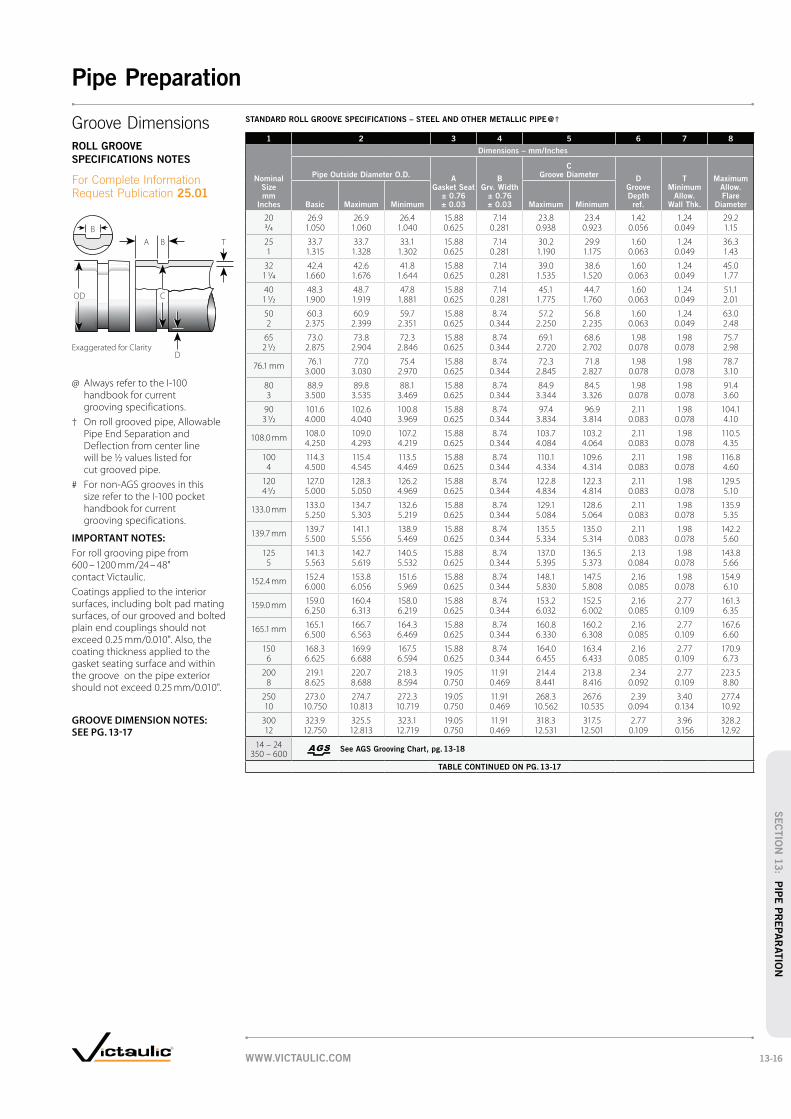
STANDARD ROLL GROOVE SPECIFICATIONS – STEEL AND OTHER METALLIC PIPE @ †
1 2 3 4 5 6 7 8
Nominal Size mm
Inches
Dimensions – mm/Inches
Pipe Outside Diameter O.D.A
Gasket Seat ± 0.76 ± 0.03
B Grv. Width
± 0.76 ± 0.03
C Groove Diameter
D Groove Depth ref.
T Minimum
Allow. Wall Thk.
Maximum Allow. Flare
DiameterBasic Maximum Minimum Maximum Minimum
20 26.9 26.9 26.4 15.88 7.14 23.8 23.4 1.42 1.24 29.23/4 1.050 1.060 1.040 0.625 0.281 0.938 0.923 0.056 0.049 1.15
25 33.7 33.7 33.1 15.88 7.14 30.2 29.9 1.60 1.24 36.31 1.315 1.328 1.302 0.625 0.281 1.190 1.175 0.063 0.049 1.43
32 42.4 42.6 41.8 15.88 7.14 39.0 38.6 1.60 1.24 45.01 1/4 1.660 1.676 1.644 0.625 0.281 1.535 1.520 0.063 0.049 1.77
40 48.3 48.7 47.8 15.88 7.14 45.1 44.7 1.60 1.24 51.11 1/2 1.900 1.919 1.881 0.625 0.281 1.775 1.760 0.063 0.049 2.01
50 60.3 60.9 59.7 15.88 8.74 57.2 56.8 1.60 1.24 63.02 2.375 2.399 2.351 0.625 0.344 2.250 2.235 0.063 0.049 2.48
65 73.0 73.8 72.3 15.88 8.74 69.1 68.6 1.98 1.98 75.72 1/2 2.875 2.904 2.846 0.625 0.344 2.720 2.702 0.078 0.078 2.98
76.1 mm 76.1 77.0 75.4 15.88 8.74 72.3 71.8 1.98 1.98 78.73.000 3.030 2.970 0.625 0.344 2.845 2.827 0.078 0.078 3.10
80 88.9 89.8 88.1 15.88 8.74 84.9 84.5 1.98 1.98 91.43 3.500 3.535 3.469 0.625 0.344 3.344 3.326 0.078 0.078 3.60
90 101.6 102.6 100.8 15.88 8.74 97.4 96.9 2.11 1.98 104.13 1/2 4.000 4.040 3.969 0.625 0.344 3.834 3.814 0.083 0.078 4.10
108.0 mm 108.0 109.0 107.2 15.88 8.74 103.7 103.2 2.11 1.98 110.54.250 4.293 4.219 0.625 0.344 4.084 4.064 0.083 0.078 4.35
100 114.3 115.4 113.5 15.88 8.74 110.1 109.6 2.11 1.98 116.84 4.500 4.545 4.469 0.625 0.344 4.334 4.314 0.083 0.078 4.60
120 127.0 128.3 126.2 15.88 8.74 122.8 122.3 2.11 1.98 129.54 1/2 5.000 5.050 4.969 0.625 0.344 4.834 4.814 0.083 0.078 5.10
133.0 mm 133.0 134.7 132.6 15.88 8.74 129.1 128.6 2.11 1.98 135.95.250 5.303 5.219 0.625 0.344 5.084 5.064 0.083 0.078 5.35
139.7 mm 139.7 141.1 138.9 15.88 8.74 135.5 135.0 2.11 1.98 142.25.500 5.556 5.469 0.625 0.344 5.334 5.314 0.083 0.078 5.60
125 141.3 142.7 140.5 15.88 8.74 137.0 136.5 2.13 1.98 143.85 5.563 5.619 5.532 0.625 0.344 5.395 5.373 0.084 0.078 5.66
152.4 mm 152.4 153.8 151.6 15.88 8.74 148.1 147.5 2.16 1.98 154.96.000 6.056 5.969 0.625 0.344 5.830 5.808 0.085 0.078 6.10
159.0 mm 159.0 160.4 158.0 15.88 8.74 153.2 152.5 2.16 2.77 161.36.250 6.313 6.219 0.625 0.344 6.032 6.002 0.085 0.109 6.35
165.1 mm 165.1 166.7 164.3 15.88 8.74 160.8 160.2 2.16 2.77 167.66.500 6.563 6.469 0.625 0.344 6.330 6.308 0.085 0.109 6.60
150 168.3 169.9 167.5 15.88 8.74 164.0 163.4 2.16 2.77 170.96 6.625 6.688 6.594 0.625 0.344 6.455 6.433 0.085 0.109 6.73
200 219.1 220.7 218.3 19.05 11.91 214.4 213.8 2.34 2.77 223.58 8.625 8.688 8.594 0.750 0.469 8.441 8.416 0.092 0.109 8.80
250 273.0 274.7 272.3 19.05 11.91 268.3 267.6 2.39 3.40 277.410 10.750 10.813 10.719 0.750 0.469 10.562 10.535 0.094 0.134 10.92
300 323.9 325.5 323.1 19.05 11.91 318.3 317.5 2.77 3.96 328.212 12.750 12.813 12.719 0.750 0.469 12.531 12.501 0.109 0.156 12.92
14 – 24 350 – 600
See AGS Grooving Chart, pg. 13-18
TABLE CONTINUED ON PG. 13-17
A B
D
B
T
COD
Exaggerated for Clarity
Groove Dimensions
ROLL GROOVE
SPECIFICATIONS NOTES
For Complete Information Request Publication 25.01
@ Always refer to the I-100 handbook for current grooving specifications.
† On roll grooved pipe, Allowable Pipe End Separation and Deflection from center line will be ½ values listed for cut grooved pipe.
# For non-AGS grooves in this size refer to the I-100 pocket handbook for current grooving specifications.
IMPORTANT NOTES:
For roll grooving pipe from 600 – 1200 mm/24 – 48" contact Victaulic.
Coatings applied to the interior surfaces, including bolt pad mating surfaces, of our grooved and bolted plain end couplings should not exceed 0.25 mm/0.010". Also, the coating thickness applied to the gasket seating surface and within the groove on the pipe exterior should not exceed 0.25 mm/0.010".
GROOVE DIMENSION NOTES: SEE PG. 13-17
WWW.VICTAULIC.COM 13-16
Pipe Preparation
SEC
TIO
N 1
3: P
IPE
PR
EPA
RATIO
N

STANDARD ROLL GROOVE SPECIFICATIONS – STEEL AND OTHER METALLIC PIPE @ †
1 2 3 4 5 6 7 8
Nominal Size mm
Inches
Dimensions – mm/Inches
Pipe Outside Diameter O.D.A
Gasket Seat ± 0.76 ± 0.03
B Grv. Width
± 0.76 ± 0.03
C Groove Diameter
Groove Depth
D ref.
T Min. Allow.
Wall Thickness
Max. Allow. Flare Dia.Basic Maximum Minimum Maximum Minimum
TABLE CONTINUED FROM PG. 13-16
355.6 355.6 357.2 354.8 23.83 11.91 350.0 349.3 2.77 3.96 359.714 14.000 14.063 13.969 0.938 0.469 13.781 13.751 0.109 0.156 14.16
377.0 mm 377.0 379.4 376.2 23.83 11.91 371.1 370.4 2.94 4.50 381.014.843 14.937 14.811 0.938 0.469 14.611 14.581 0.116 0.177 15.00
15" 381.0 382.6 380.2 23.83 11.91 375.4 374.7 2.77 4.19 385.115.000 15.063 14.969 0.938 0.469 14.781 14.751 0.109 0.165 15.16
406.4 406.4 408.0 405.6 23.83 11.91 400.8 400.1 2.77 4.19 410.516 16.000 16.063 15.969 0.938 0.469 15.781 15.751 0.109 0.165 16.16
426.0 mm 426.0 428.4 425.2 23.83 11.91 419.5 418.6 3.28 4.50 430.016.772 16.866 16.740 0.938 0.469 16.514 16.479 0.129 0.177 16.93
457.0 457.0 458.8 456.4 25.40 11.91 451.6 450.9 2.77 4.78 461.318 18.000 18.063 17.969 1.000 0.469 17.781 17.751 0.109 0.188 18.16
480.0 mm 480.0 482.4 479.2 25.40 11.91 473.1 472.2 3.45 5.99 484.118.898 18.992 18.867 1.000 0.469 18.626 18.591 0.136 0.236 19.06
508.0 508.0 509.6 507.2 25.40 11.91 502.4 501.7 2.77 4.78 512.120 20.000 20.063 19.969 1.000 0.469 19.781 19.751 0.109 0.188 20.16
530.0 mm 530.0 532.4 529.2 25.40 11.91 522.5 521.6 3.73 5.99 534.220.866 20.960 20.835 1.000 0.469 20.572 20.537 0.147 0.236 21.03
559.0 559.0 560.4 558.0 25.40 12.70 550.1 549.3 4.37 4.78 563.922 22.000 22.063 21.969 1.000 0.500 21.656 21.626 0.172 0.188 22.20
610.0 610.0 611.2 608.8 25.40 12.70 600.9 600.1 4.37 5.54 614.724 24.000 24.063 23.969 1.000 0.500 23.656 23.626 0.172 0.218 24.20
630.0 mm 630.0 632.4 629.2 25.40 12.70 621.3 620.4 4.37 7.01 635.024.803 24.897 24.772 1.000 0.500 24.459 24.424 0.172 0.276 25.00
650 660.4 662.8 659.6 45.45 15.88 647.7 646.1 6.35 6.35 665.526 # 26.000 26.093 25.969 1.75 0.625 25.500 25.437 0.250 0.250 26.20
700 711.0 713.6 710.4 45.45 15.88 698.5 696.9 6.35 6.35 716.328 # 28.000 28.093 27.969 1.75 0.625 27.500 27.437 0.250 0.250 28.20
750 762.0 764.4 761.2 45.45 15.88 749.3 747.7 6.35 6.35 767.130 # 30.000 30.093 29.969 1.75 0.625 29.500 29.437 0.250 0.250 30.20
800 813.0 815.2 812.0 45.45 15.88 800.1 798.5 6.35 6.35 817.932 # 32.000 32.093 31.969 1.75 0.625 31.500 31.437 0.250 0.250 32.20
900 914.0 916.8 913.6 45.45 15.88 901.7 900.1 6.35 6.35 919.536 # 36.000 36.093 35.969 1.75 0.625 35.500 35.437 0.250 0.250 36.20
1050 1067.0 1069.2 1066.0 50.80 15.88 1054.1 1052.5 6.35 6.35 1071.842 # 42.000 42.093 41.969 2.00 0.625 41.500 41.437 0.250 0.250 42.20
@ Always refer to the I-100 handbook for current grooving specifications.
# Gasket Seat tolerances for sizes 650 – 1050 mm/26 – 42" are +0.8 mm and -1.5 mm/+0.03" and -0.06".
IMPORTANT NOTES:
For roll grooving pipe from 600 – 1200 mm/24 – 48" contact Victaulic.
Coatings applied to the interior surfaces, including bolt pad mating surfaces, of our grooved and bolted plain end couplings should not exceed 0.25 mm/0.010". Also, the coating thickness applied to the gas-ket seating surface and within the groove on the pipe exterior should not exceed 0.25 mm/0.010".
GROOVE DIMENSION NOTES:
Column 1: Nominal Pipe Size
Column 2: Pipe Outside DiameterThe average pipe outside diameter must not vary from the specifications listed in the tables on the following pages. Maximum allowable pipe ovality should not vary by more than 1%. Greater variations between the major and minor diameters will result in difficult coupling assembly. For carbon steel pipe, the maximum allowable tolerance from square-cut pipe ends is 0.8 mm/0.030" for 20 – 90 mm/¾ – 3 ½" sizes; 1.1 mm/0.045" for 100 – 150 mm/4 – 6" sizes; and 1.5 mm/0.060" for 200 mm/8" and larger sizes. This is measured from the true square line. Any internal and external weld beads or seams must be ground flush to the pipe surface. The inside diameter of the pipe end must be cleaned to remove coarse scale, dirt, and other foreign material that might interfere with or damage grooving rolls.
Column 3: Gasket Seat “A” Dimension The “A” dimension, or the distance from the pipe end to the groove, identifies the gasket seating area. This area must be free from indentations, projections (including weld seams), and roll marks from the pipe end to the groove to ensure a leak-tight seal for the gasket. All oil, grease, and dirt must be removed.
Column 4: Groove Width “B” Dimension The “B” dimension, or groove width, controls expansion, contraction, and angular deflection of flexible couplings by the distance it is located from the pipe and its width in relation to the coupling housings’ “key” width.
Column 5: Groove Outside Diameter “C” DimensionThe “C” dimension is the proper diameter at the base of the groove. This dimension must be within the diameter’s tolerance and concentric with the OD for proper coupling fit. The groove must be of uniform depth for the entire pipe circumference.
Column 6: Groove Depth “D” Dimension The “D” dimension is the normal depth of the groove and is a reference for a “trial groove” only. Variations in pipe OD affect this dimension and must be altered, if necessary, to keep the “C” dimension within tolerance. This groove must conform to the “C” dimension described above.
Column 7: Minimum Allowable Wall Thickness “T” DimensionThe “T” dimension is the lightest grade (minimum, nominal wall thickness) of pipe that is suitable for cut or roll grooving. Pipe that is less than the minimum, nominal wall thickness for cut grooving may be roll grooved or adapted for Victaulic couplings by using Vic-Ring adapters. Vic-Ring adapters can be used in the following situations (contact Victaulic for details):
grooving
Column 8: Maximum Allowable Pipe-End Flare Diameter Dimension (Standard Roll Groove Only)Maximum allowable pipe-end flare diameter is measured at the extreme pipe-end diameter.
A B
D
B
T
COD
Exaggerated for Clarity
Groove Dimensions
ROLL GROOVE
SPECIFICATIONS NOTES
For Complete Information Request Publication 25.01
WWW.VICTAULIC.COM13-17
Pipe Preparation
SEC
TIO
N 1
3:
PIP
E P
REPA
RATIO
N
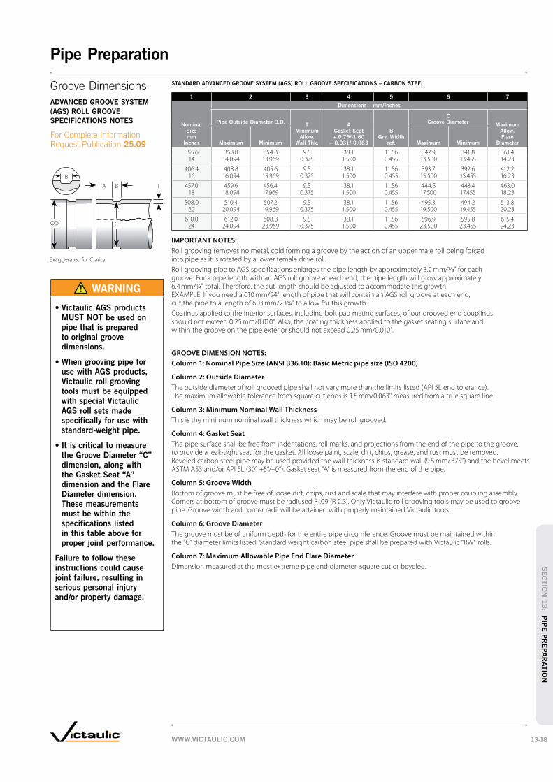
STANDARD ADVANCED GROOVE SYSTEM (AGS) ROLL GROOVE SPECIFICATIONS – CARBON STEEL
1 2 3 4 5 6 7
Nominal Size mm
Inches
Dimensions – mm/Inches
Pipe Outside Diameter O.D.T
Minimum Allow.
Wall Thk.
A Gasket Seat + 0.79/-1.60
+ 0.031/-0.063
B Grv. Width
ref.
C Groove Diameter
Maximum Allow. Flare
DiameterMaximum Minimum Maximum Minimum
355.6 358.0 354.8 9.5 38.1 11.56 342.9 341.8 361.414 14.094 13.969 0.375 1.500 0.455 13.500 13.455 14.23
406.4 408.8 405.6 9.5 38.1 11.56 393.7 392.6 412.216 16.094 15.969 0.375 1.500 0.455 15.500 15.455 16.23
457.0 459.6 456.4 9.5 38.1 11.56 444.5 443.4 463.018 18.094 17.969 0.375 1.500 0.455 17.500 17.455 18.23
508.0 510.4 507.2 9.5 38.1 11.56 495.3 494.2 513.820 20.094 19.969 0.375 1.500 0.455 19.500 19.455 20.23
610.0 612.0 608.8 9.5 38.1 11.56 596.9 595.8 615.424 24.094 23.969 0.375 1.500 0.455 23.500 23.455 24.23
IMPORTANT NOTES:
Roll grooving removes no metal, cold forming a groove by the action of an upper male roll being forced into pipe as it is rotated by a lower female drive roll.
Roll grooving pipe to AGS specifications enlarges the pipe length by approximately 3.2 mm/1/8" for each groove. For a pipe length with an AGS roll groove at each end, the pipe length will grow approximately 6.4 mm/¼" total. Therefore, the cut length should be adjusted to accommodate this growth. EXAMPLE: If you need a 610 mm/24" length of pipe that will contain an AGS roll groove at each end, cut the pipe to a length of 603 mm/23¾" to allow for this growth.
Coatings applied to the interior surfaces, including bolt pad mating surfaces, of our grooved end couplings should not exceed 0.25 mm/0.010". Also, the coating thickness applied to the gasket seating surface and within the groove on the pipe exterior should not exceed 0.25 mm/0.010".
GROOVE DIMENSION NOTES:
Column 1: Nominal Pipe Size (ANSI B36.10); Basic Metric pipe size (ISO 4200)
Column 2: Outside Diameter
The outside diameter of roll grooved pipe shall not vary more than the limits listed (API 5L end tolerance). The maximum allowable tolerance from square cut ends is 1.5 mm/0.063" measured from a true square line.
Column 3: Minimum Nominal Wall Thickness
This is the minimum nominal wall thickness which may be roll grooved.
Column 4: Gasket Seat
The pipe surface shall be free from indentations, roll marks, and projections from the end of the pipe to the groove, to provide a leak-tight seat for the gasket. All loose paint, scale, dirt, chips, grease, and rust must be removed. Beveled carbon steel pipe may be used provided the wall thickness is standard wall (9.5 mm/.375") and the bevel meets ASTM A53 and/or API 5L (30° +5°/–0°). Gasket seat “A” is measured from the end of the pipe.
Column 5: Groove Width
Bottom of groove must be free of loose dirt, chips, rust and scale that may interfere with proper coupling assembly. Corners at bottom of groove must be radiused R .09 (R 2.3). Only Victaulic roll grooving tools may be used to groove pipe. Groove width and corner radii will be attained with properly maintained Victaulic tools.
Column 6: Groove Diameter
The groove must be of uniform depth for the entire pipe circumference. Groove must be maintained within the “C” diameter limits listed. Standard weight carbon steel pipe shall be prepared with Victaulic “RW” rolls.
Column 7: Maximum Allowable Pipe End Flare Diameter
Dimension measured at the most extreme pipe end diameter, square cut or beveled.
Exaggerated for Clarity
OD C
B
A B T
Groove Dimensions
ADVANCED GROOVE SYSTEM
(AGS) ROLL GROOVE
SPECIFICATIONS NOTES
For Complete Information Request Publication 25.09
WARNING
MUST NOT be used on
pipe that is prepared
to original groove
dimensions.
use with AGS products,
Victaulic roll grooving
tools must be equipped
with special Victaulic
AGS roll sets made
specifically for use with
standard-weight pipe.
the Groove Diameter “C”
dimension, along with
the Gasket Seat “A”
dimension and the Flare
Diameter dimension.
These measurements
must be within the
specifications listed
in this table above for
proper joint performance.
Failure to follow these
instructions could cause
joint failure, resulting in
serious personal injury
and/or property damage.
WWW.VICTAULIC.COM 13-18
Pipe Preparation
SEC
TIO
N 1
3: P
IPE
PR
EPA
RATIO
N

COPPER TUBING ROLL GROOVE SPECIFICATIONS FOR EUROPEAN STANDARD – EN1057 @
1 2 3 4 5 6 7
Nominal Size mm
Actual Outer Dia. Gasket Seat Groove Width Groove Dia. Grv. Depth Flare Dia.
Max. mm
Inches
Min. mm
Inches
A Basic mm
Inches
A Max. mm
Inches
A Min. mm
Inches
B Max. mm
Inches
B Min. mm
Inches
C Max. mm
Inches
C Min. mm
Inches
D (Ref. only)
mm Inches
Max. mm
Inches
54.0 54.07 53.93 15.87 16.64 15.11 8.38 7.62 51.51 51.00 1.25 56.392.129 2.123 0.625 0.655 0.595 0.330 0.300 2.028 2.008 0.049 2.220
64.0 64.07 63.93 15.87 16.64 15.11 8.38 7.62 61.47 60.96 1.27 66.412.522 2.517 0.625 0.655 0.595 0.330 0.300 2.420 2.400 0.050 2.615
66.7 66.77 66.63 15.87 16.64 15.11 8.38 7.62 64.14 63.63 1.27 69.092.629 2.623 0.625 0.655 0.595 0.330 0.300 2.525 2.505 0.050 2.720
76.1 76.17 76.03 15.87 16.64 15.11 8.38 7.62 73.41 72.90 1.35 78.612.999 2.993 0.625 0.655 0.595 0.330 0.300 2.890 2.870 0.053 3.095
88.9 88.79 88.83 15.87 16.64 15.11 8.38 7.62 85.70 85.19 1.60 91.633.496 3.497 0.625 0.655 0.595 0.330 0.300 3.374 3.354 0.063 3.607
108.0108.07 107.93 15.87 16.64 15.11 8.38 7.62 104.80 104.29 1.60 110.544.255 4.249 0.625 0.655 0.595 0.330 0.300 4.126 4.106 0.063 4.352
133.0133.20 132.80 15.87 16.64 15.11 8.38 7.62 129.29 128.78 1.85 135.795.244 5.228 0.625 0.655 0.595 0.330 0.300 5.090 5.070 0.073 5.346
159.0 159.20 158.80 15.87 16.64 15.11 8.38 7.62 155.30 154.79 1.85 161.806.280 6.252 0.625 0.655 0.595 0.330 0.300 6.114 6.094 0.073 6.370
@ Always refer to the I-600 handbook for current grooving specifications.
GROOVE DIMENSION NOTES:
Column 1: Nominal EN1057 drawn copper tubing size as indicated in the chart heading
Column 2: Outside Diameter
The outside diameter of roll grooved tubing shall not vary more than the tolerance listed. The maximum allowable tolerance from square cut ends is 0.8 mm/0.030" for 54.0 – 88.9 mm; 1.1 mm/0.045" for 108.0 – 159.0 mm, measured from true square line.
Column 3: Gasket Seat
The tubing surface shall be free from indentations, roll marks, and projections from the end of the tubing to the groove, to provide a leak-tight seat for the gasket. All loose scales, dirt, chips and grease must be removed.
Column 4: Groove Width
Bottom of groove to be free of loose dirt, chips and scale that may interfere with proper coupling assembly.
Column 5: Groove Outside Diameter
The groove must be uniform depth for the entire tubing circumference. Groove must be maintained within the “C” diameter tolerance listed.
Column 6: Groove Depth
For reference only. Groove must conform to the groove diameter “C” listed.
Column 7: Maximum Allowable End Flare Diameter
Measured at the most extreme tubing end diameter.
A B
OD C
B
D
Exaggerated for Clarity
Groove Dimensions
COPPER TUBING ROLL GROOVE
SPECIFICATIONS NOTES FOR
EUROPEAN STANDARD
For Complete Information Request Publication 22.11
WWW.VICTAULIC.COM13-19
Pipe Preparation
SEC
TIO
N 1
3:
PIP
E P
REPA
RATIO
N

STANDARD CUT GROOVE SPECIFICATIONS – STEEL AND OTHER METALLIC PIPE @
1 2 3 4 5 6 7
Nominal Size mm
Inches
Dimensions – mm/Inches
Pipe Outside Diameter O.D.A
Gasket Seat ± 0.76 ± 0.03
B Grv. Width
± 0.76 ± 0.03
C Groove Diameter
D Groove Depth ref.
T Minimum
Allow. Wall Thk.Basic Maximum Minimum Maximum Minimum
20 26.9 26.9 26.4 15.88 7.95 23.8 23.4 1.42 2.873/4 1.050 1.060 1.040 0.625 0.313 0.938 0.923 0.056 0.113
25 33.7 33.7 33.1 15.88 7.95 30.2 29.9 1.60 3.381 1.315 1.328 1.302 0.625 0.313 1.190 1.175 0.063 0.133
32 42.4 42.6 41.8 15.88 7.95 39.0 38.6 1.60 3.561 1/4 1.660 1.676 1.644 0.625 0.313 1.535 1.520 0.063 0.140
40 48.3 48.7 47.8 15.88 7.95 45.1 44.7 1.60 3.681 1/2 1.900 1.919 1.881 0.625 0.313 1.775 1.760 0.063 0.145
50 60.3 60.9 59.7 15.88 7.95 57.2 56.8 1.60 3.912 2.375 2.399 2.351 0.625 0.313 2.250 2.235 0.063 0.154
65 73.0 73.8 72.3 15.88 7.95 69.1 68.6 1.98 4.782 1/2 2.875 2.904 2.846 0.625 0.313 2.720 2.702 0.078 0.188
76.1 mm 76.1 77.0 75.4 15.88 7.95 72.3 71.8 1.98 4.783.000 3.030 2.970 0.625 0.313 2.845 2.827 0.078 0.188
80 88.9 89.8 88.1 15.88 7.95 84.9 84.5 1.98 4.783 3.500 3.535 3.469 0.625 0.313 3.344 3.326 0.078 0.188
90 101.6 102.6 100.8 15.88 7.95 97.4 96.9 2.11 4.783 1/2 4.000 4.040 3.969 0.625 0.313 3.834 3.814 0.083 0.188
108.0 mm 108.0 109.0 107.2 15.88 9.53 103.7 103.2 2.11 5.174.250 4.293 4.219 0.625 0.375 4.084 4.064 0.083 0.203
100 114.3 115.4 113.5 15.88 9.53 110.1 109.6 2.11 5.174 4.500 4.545 4.469 0.625 0.375 4.334 4.314 0.083 0.203
120 127.0 128.3 126.2 15.88 9.53 122.8 122.3 2.11 5.174 1/2 5.000 5.050 4.969 0.625 0.375 4.834 4.814 0.083 0.203
133.0 mm 133.0 134.7 132.6 15.88 9.53 129.1 128.6 2.11 5.175.250 5.303 5.219 0.625 0.375 5.084 5.064 0.083 0.203
139.7 mm 139.7 141.1 138.9 15.88 9.53 135.5 135.0 2.11 5.175.500 5.556 5.469 0.625 0.375 5.334 5.314 0.083 0.203
125 141.3 142.7 140.5 15.88 9.53 137.0 136.5 2.13 5.175 5.563 5.619 5.532 0.625 0.375 5.395 5.373 0.084 0.203
152.4 mm 152.4 153.8 151.6 15.88 9.53 148.1 147.5 2.16 5.566.000 6.056 5.969 0.625 0.375 5.830 5.808 0.085 0.219
159.0 mm 159.0 160.4 158.0 15.88 9.53 153.2 152.5 2.16 6.326.250 6.313 6.219 0.625 0.375 6.032 6.002 0.085 0.249
165.1 mm 165.1 166.7 164.3 15.88 9.53 160.8 160.2 2.16 5.566.500 6.563 6.469 0.625 0.375 6.330 6.308 0.085 0.219
150 168.3 169.9 167.5 15.88 9.53 164.0 163.4 2.16 5.566 6.625 6.688 6.594 0.625 0.375 6.455 6.433 0.085 0.219
200 219.1 220.7 218.3 19.05 11.13 214.4 213.8 2.34 6.058 8.625 8.688 8.594 0.750 0.438 8.441 8.416 0.092 0.238
250 273.0 274.7 272.3 19.05 12.70 268.3 267.6 2.39 6.3510 10.750 10.813 10.719 0.750 0.500 10.562 10.535 0.094 0.250
300 323.9 325.5 323.1 19.05 12.70 318.3 317.5 2.77 7.0912 12.750 12.813 12.719 0.750 0.500 12.531 12.501 0.109 0.279
TABLE CONTINUED ON PG. 13-21
* 14 mm/9/16"(0.562") width groove is required in sizes 550 – 600 mm/22 – 24" in order to obtain the maximum allowable pipe end movement listed in Performance Data Charts. 12 mm/½" width groove will give ½ the maximum allowable shown for 550 – 600 mm/22 – 24". For double groove tool bit information, contact Victaulic.
@ Always refer to the I-100 handbook for current grooving specifications.
A B
OD C
B
D
T
Exaggerated for Clarity
Groove Dimensions
STANDARD CUT GROOVE
SPECIFICATIONS NOTES
For Complete Information Request Publication 25.01
GROOVE DIMENSION NOTES:
Column 1: Nominal Pipe Size
Column 2: Outside Diameter
The outside diameter of cut grooved pipe shall not vary more than the tolerance listed. For carbon steel pipe the maximum allowable tolerance from square cut ends to 0.76 mm/0.030" for 20 – 90 mm/¾ – 3½"; 1.14 mm/0.045" for 100 – 150 mm/4 – 6"; and 1.5 mm/0.060" for sizes 200 mm/8" O.D. and above measured from true square line.
Column 3: Gasket Seat
The pipe surface shall be free from indentations, roll marks, and projections from the end of the pipe to the groove, to provide a leak-tight seal for the gasket. All loose paint, scale, dirt, chips, grease and rust must be removed. It continues to be Victaulic’s first recommendation that pipe be square cut. When using beveled pipe contact Victaulic for details. Square cut pipe must be used with FlushSeal and EndSeal gaskets. Gasket seat “A” is measured from the end of the pipe.
Column 4: Groove Width
The bottom of groove to be free of loose dirt, chips, rust and scale that may interfere with proper coupling assembly. Maximum permissible radius at bottom of groove is 3.8 mm/.015".
Column 5: Groove Outside Diameter
The groove must be of uniform depth for the entire pipe circumference. Groove must be maintained within the “C” diameter tolerance listed.
Column 6: Groove Depth
For reference only. Groove must conform to the groove diameter “C” listed.
Column 7: Minimum Allowable Wall Thickness
This is the minimum wall thickness which may be cut grooved.
WWW.VICTAULIC.COM 13-20
Pipe Preparation
SEC
TIO
N 1
3: P
IPE
PR
EPA
RATIO
N

STANDARD CUT GROOVE SPECIFICATIONS – STEEL AND OTHER METALLIC PIPE @
1 2 3 4 5 6 7
Nominal Size mm
Inches
Dimensions – mm/Inches
Pipe Outside Diameter O.D.A
Gasket Seat ± 0.76 ± 0.03
B Grv. Width
± 0.76 ± 0.03
C Groove Diameter
Groove Depth
D ref.
T Min. Allow.
Wall ThicknessBasic Maximum Minimum Maximum Minimum
TABLE CONTINUED FROM PG. 13-20
355.6 355.6 357.2 354.8 23.83 12.70 350.0 349.3 2.77 7.1414 14.000 14.063 13.969 0.938 0.500 13.781 13.751 0.109 0.281
377.0 mm 377.0 379.4 376.2 23.83 12.70 371.1 370.4 2.94 8.0014.843 14.937 14.811 0.938 0.500 14.611 14.581 0.116 0.315
15" 381.0 382.6 380.2 23.83 12.70 375.4 374.7 2.77 7.9215.000 15.063 14.969 0.938 0.500 14.781 14.751 0.109 0.312
406.4 406.4 408.0 405.6 23.83 12.70 400.8 400.1 2.77 7.9216 16.000 16.063 15.969 0.938 0.500 15.781 15.751 0.109 0.312
426.0 mm 426.0 428.4 425.2 23.83 12.70 419.5 418.6 3.28 8.5116.772 16.866 16.740 0.938 0.500 16.514 16.479 0.129 0.335
457.0 457.0 458.8 456.4 25.40 12.70 451.6 450.9 2.77 7.9218 18.000 18.063 17.969 1.000 0.500 17.781 17.751 0.109 0.312
480.0 mm 480.0 482.4 479.1 25.40 12.70 473.1 472.2 3.45 8.9918.898 18.992 18.863 1.000 0.500 18.626 18.591 0.136 0.354
508.0 508.0 509.6 507.2 25.40 12.70 502.4 501.7 2.77 7.9220 20.000 20.063 19.969 1.000 0.500 19.781 19.751 0.109 0.312
530.0 mm 530.0 532.4 529.2 25.40 12.70 522.5 521.6 3.73 8.9920.866 20.960 20.835 1.000 0.500 20.572 20.537 0.147 0.354
559.0 559.0 560.4 558.0 25.40 14.30 550.1 549.3 4.37 9.5322 22.000 22.063 21.969 1.000 0.563 21.656 21.626 0.172 0.375
610.0 610.0 611.2 608.8 25.40 14.30 600.9 600.1 4.37 9.5324 24.000 24.063 23.969 1.000 0.563 23.656 23.626 0.172 0375
630.0 mm 630.0 632.4 629.2 25.40 14.30 621.3 620.4 4.37 10.0024.803 24.897 24.772 1.000 0.563 24.459 24.424 0.172 0.394
650 660.4 662.8 659.6 45.45 15.88 647.7 646.1 6.35 15.8826 26.000 26.093 25.969 1.75 0.625 25.500 25.437 0.250 0.625
700 711.0 713.6 710.4 45.45 15.88 698.5 696.9 6.35 15.8828 28.000 28.093 27.969 1.75 0.625 27.500 27.437 0.250 0.625
28" 733.4 735.0 732.6 25.40 15.88 724.7 723.9 4.37 11.1028.875 28.938 28.844 1.00 0.625 28.531 28.501 0.172 0.437
750 762.0 764.4 761.2 45.45 15.88 749.3 747.7 6.35 15.8830 30.000 30.093 29.969 1.75 0.625 29.500 29.437 0.250 0.625
30" 787.4 789.0 786.6 25.4 15.88 777.1 776.3 5.16 12.7031.000 31.063 30.969 1.00 0.625 30.594 30.564 0.203 0.500
800 813.0 815.2 812.0 45.45 15.88 800.1 798.5 6.35 15.8832 32.000 32.093 31.969 1.75 0.625 31.500 31.437 0.250 0.625
900 914.0 916.8 913.6 45.45 15.88 901.7 900.1 6.35 15.8836 36.000 36.093 35.969 1.75 0.625 35.500 35.437 0.250 0.625
1050 1067.0 1069.2 1066.0 50.80 15.88 1054.1 1052.5 6.35 15.8842 42.000 42.093 41.969 2.00 0.625 41.500 41.437 0.250 0.625
* 14 mm/9/16"(0.562") width groove is required in sizes 550 – 600 mm/22 – 24" in order to obtain the maximum allowable pipe end movement listed in Performance Data Charts. 12 mm/½" width groove will give ½ the maximum allowable shown for 550 – 600 mm/22 – 24". For double groove tool bit information, contact Victaulic.
@ Always refer to the I-100 handbook for current grooving specifications.
A B
OD C
B
D
T
Exaggerated for Clarity
Groove Dimensions
STANDARD CUT GROOVE
SPECIFICATIONS NOTES
For Complete Information Request Publication 25.01
GROOVE DIMENSION NOTES:
Column 1: Nominal Pipe Size
Column 2: Outside Diameter
The outside diameter of cut grooved pipe shall not vary more than the tolerance listed. For carbon steel pipe the maximum allowable tolerance from square cut ends to 0.76 mm/0.030" for 20 – 90 mm/¾ – 3½"; 1.14 mm/0.045" for 100 – 150 mm/4 – 6"; and 1.5 mm/0.060" for sizes 200 mm/8" O.D. and above measured from true square line.
Column 3: Gasket Seat
The pipe surface shall be free from indentations, roll marks, and projections from the end of the pipe to the groove, to provide a leak-tight seal for the gasket. All loose paint, scale, dirt, chips, grease and rust must be removed. It continues to be Victaulic’s first recommendation that pipe be square cut. When using beveled pipe contact Victaulic for details. Square cut pipe must be used with FlushSeal and EndSeal gaskets. Gasket seat “A” is measured from the end of the pipe.
Column 4: Groove Width
The bottom of groove to be free of loose dirt, chips, rust and scale that may interfere with proper coupling assembly. Maximum permissible radius at bottom of groove is 3.8 mm/.015".
Column 5: Groove Outside Diameter
The groove must be of uniform depth for the entire pipe circumference. Groove must be maintained within the “C” diameter tolerance listed.
Column 6: Groove Depth
For reference only. Groove must conform to the groove diameter “C” listed.
Column 7: Minimum Allowable Wall Thickness
This is the minimum wall thickness which may be cut grooved.
WWW.VICTAULIC.COM13-21
Pipe Preparation
SEC
TIO
N 1
3:
PIP
E P
REPA
RATIO
N

“ES” CUT GROOVE SPECIFICATIONS @
1 2 3 4 5 6 7
Size Pipe Outside Dia. mm
Inches
Dimensions – mm/Inches
Nominal Size mm
Inches
Actual Outside
Diameter mm
Inches
Gasket Seat A Grv. Width B Groove Diameter CD
Groove Depth ref.
T Minimum
Allow. Wall
Thick.Tolerance
+ – Basic Tol. Basic
Tol. +0.25 +0.010 Basic
Tol. +0.00
+0.000
50 60.3 +0.61 -0.61 14.27 ±0.25 6.48 -0.13 57.15 -0.38 1.60 3.912 2.375 +0.024 -0.024 0.562 ±0.010 0.255 -0.005 2.250 -0.015 0.063 0.154
65 73.0 +0.74 -0.74 14.27 ±0.25 6.48 -0.13 69.09 -0.46 1.98 4.782 1/2 2.875 +0.029 -0.029 0.562 ±0.010 0.255 -0.005 2.720 -0.018 0.078 0.188
80 88.9 +0.89 -0.79 14.27 ±0.25 6.48 -0.13 84.94 -0.46 1.98 4.783 3.500 +0.035 -0.031 0.562 ±0.010 0.255 -0.005 3.344 -0.018 0.078 0.188
100 114.3 +1.14 -0.79 15.37 ±0.38 7.75 -0.13 110.08 -0.51 2.11 5.164 4.500 +0.045 -0.031 0.605 ±0.015 0.305 -0.005 4.334 -0.020 0.083 0.203
150 168.3 +1.60 -0.79 15.37 ±0.38 7.75 -0.13 163.96 0.56 2.16 5.566 6.625 +0.063 -0.031 0.605 ±0.015 0.305 -0.005 6.455 -0.022 0.085 0.219
200 219.1 +1.60 -0.79 18.14 ±0.38 10.16 -0.25 214.40 -0.64 2.34 6.058 8.625 +0.063 -0.031 0.714 ±0.015 0.400 -0.010 8.441 -0.025 0.092 0.238
250 273.0 +1.60 -0.79 18.14 ±0.38 10.16 -0.25 268.28 -0.69 2.39 6.3510 10.750 +0.063 -0.031 0.714 ±0.015 0.400 -0.010 10.562 -0.027 0.094 0.250
300 323.9 +1.60 -0.79 18.14 ±0.38 10.16 -0.25 318.29 -0.76 2.77 7.0912 12.750 +0.063 -0.031 0.714 ±0.015 0.400 -0.010 12.531 -0.030 0.109 0.279
@ Always refer to the I-100 handbook for current grooving specifications.
IMPORTANT NOTES:
Coatings applied to the interior surfaces, including bolt pad mating surfaces, of our grooved and bolted plain end couplings should not exceed 0.25 mm/0.010", Also, the coating thickness applied to the gasket seating surface and within the groove on the pipe exterior should not exceed 0.25 mm/0.010".
“ES” ROLL GROOVE SPECIFICATIONS @
1 2 3 4 5 6 7 8
Size Pipe Outside Dia. mm
Inches
Dimensions – mm/Inches
Nominal Size mm
Inches
Actual Out. Dia.
mm Inches
Gasket Seat A Grv. Width B Groove Dia. C
D Groove Depth ref.
T Minimum
Allow. Wall
Thick.
Maximum Allow. Flare
DiameterTolerance
+ – Basic Tol. Basic
Tol. +0.00
+0.000 Basic
Tol. +0.00
+0.000
50 60.3 +0.61 -0.61 14.43 ±0.51 6.35 +0.38 57.15 -0.38 1.60 1.65 63.02 2.375 +0.024 -0.024 0.572 -0.020 0.250 +0.015 2.250 -0.015 0.063 0.065 2.48
65 73.0 +0.74 -0.74 14.53 ±0.51 6.35 +0.38 69.09 -0.46 1.98 2.11 75.72 1/2 2.875 +0.029 -0.029 0.572 -0.020 0.250 +0.015 2.720 -0.018 0.078 0.083 2.98
80 88.9 +0.89 -0.79 14.53 ±0.51 6.35 +0.38 84.94 -0.46 2.11 2.11 91.43 3.500 +0.035 -0.031 0.572 -0.020 0.250 +0.015 3.344 -0.018 0.083 0.083 3.60
100 114.3 +1.14 -0.79 15.49 ±0.51 7.62 +0.51 110.08 -0.51 2.11 2.11 116.84 4.500 +0.045 -0.031 0.610 -0.020 0.300 +0.020 4.334 -0.020 0.083 0.083 4.60
150 168.3 +1.60 -0.79 15.49 ±0.51 7.62 +0.51 163.96 0.56 2.16 2.77 170.96 6.625 +0.063 -0.031 0.610 -0.020 0.300 +0.020 6.455 -0.022 0.085 0.109 6.73
200 219.1 +1.60 -0.79 18.26 ±0.51 9.91 +0.51 214.40 -0.64 2.34 2.77 223.58 8.625 +0.063 -0.031 0.719 -0.020 0.390 +0.020 8.441 -0.025 0.092 0.109 8.80
250 273.0 +1.60 -0.79 18.26 ±0.51 9.91 +0.51 268.28 -0.69 2.39 3.40 277.410 10.750 +0.063 -0.031 0.719 -0.020 0.390 +0.020 10.562 -0.027 0.094 0.134 10.92
300 323.9 +1.60 -0.79 18.26 ±0.51 9.91 +0.51 318.29 -0.76 2.77 3.96 328.212 12.750 +0.063 -0.031 0.719 -0.020 0.390 +0.020 12.531 -0.030 0.109 0.156 12.92
@ Always refer to the I-100 handbook for current grooving specifications.
IMPORTANT NOTES:
Coatings applied to the interior surfaces, including bolt pad mating surfaces, of our grooved and bolted plain end couplings should not exceed 0.25 mm/0.010", Also, the coating thickness applied to the gasket seating surface and within the groove on the pipe exterior should not exceed 0.25 mm/0.010".
A B
D
B
T
COD
Exaggerated for Clarity
A B
OD C
B
D
T
Exaggerated for Clarity
Groove Dimensions
“ES” ROLL/CUT GROOVE
SPECIFICATIONS NOTES
For Complete Information Request Publication 25.02
GROOVE DIMENSION NOTES:
Column 1: Nominal Pipe Size
Nominal metric (ISO) pipe size.
Column 2: Outside Diameter
Metric (ISO) outside diameter. The outside diameter of roll grooved pipe shall not vary more than the tolerance listed. For carbon steel pipe, the maximum allowable tolerance from square cut ends is 0.030" for 20 – 90 mm/¾ – 3½"; 0.045" for 100 – 150 mm/4 – 6"; and 0.060" for sizes 203.2 mm and above measured from true square line. For (ISO) metric pipe, the maximum allowable tolerance from square cut ends is 0.76 mm for sizes 20 – 80 mm; 1.14 mm for sizes 100 – 150 mm; and 1.52 mm for sizes 200 mm and above, measured from the true square line.
Column 3: Gasket Seat
The pipe surface shall be free from indentations, roll marks, and projections from the end of the pipe to the groove, to provide a leak-tight seal for the gasket. All loose paint, scale, dirt, chips, grease and rust must be removed. Square cut pipe must be used with FlushSeal and EndSeal gaskets. Gasket seat “A” is measured from the end of the pipe.
Column 4: Groove Width
The bottom of groove to be free of loose dirt, chips, rust and scale that may interfere with proper coupling assembly. Corners at bottom of roll groove must be radiused. For carbon steel pipe, 0.04R on 40 – 300 mm/1½ – 12". For (ISO) metric pipe, 1.2R mm on 20 – 300 mm.
Column 5: Groove Outside Diameter
The groove must be uniform depth for the entire pipe circumference. Groove must be maintained within the “C” diameter tolerance listed.
Column 6: Groove Depth
For reference only. Groove must conform to the groove diameter “C” listed.
Column 7: Minimum Allowable Wall Thickness
This is the minimum wall thickness which may be grooved.
Column 8: Maximum Allowable End Flare Diameter
Measured at the most extreme pipe end diameter square cut or beveled.
WWW.VICTAULIC.COM 13-22
Pipe Preparation
SEC
TIO
N 1
3: P
IPE
PR
EPA
RATIO
N

Style No. Product Description Page No. Publ. No.
SECTION 1: COUPLINGS
Style 07 Zero-Flex Rigid Coupling 1-16 06.02
Style HP-70 Rigid Coupling 1-28 06.12
Style 72 Outlet Coupling 1-26 06.10
Style 75 Flexible Coupling 1-19 06.05
Style 77 Standard Flexible Coupling 1-17 06.04
Style 78 Snap-Joint Coupling 1-25 06.09
Style 741 Vic-Flange Adapter PN10 and PN16 1-21 06.06
Vic-Flange Adapter ANSI Class 150 1-22 06.06
Style 743 Vic-Flange Adapter ANSI Class 300 1-23 06.06
Style 750 Reducing Coupling 1-24 06.08
Style 770 Large Diameter Pipe Coupling 1-20 06.03
Style 791 Vic-Boltless Coupling 1-27 06.11
Style 792 Vic-Boltless Assembly Tool 1-27 06.11
ENDSEAL COUPLING AND FITTINGS
Style HP-70ES EndSeal Coupling for Plastic Coated Pipe 1-29 06.13
No. 22-ES EndSeal Header Tee for Plastic Coated Pipe 1-30 07.03
No. 35-ES EndSeal Cross for Plastic Coated Pipe 1-30 07.03
No. 62-ES EndSeal 90° Elbow for Plastic Coated Pipe 1-30 07.03
No. 63-ES EndSeal 45° Elbow for Plastic Coated Pipe 1-30 07.03
No. 64-ES EndSeal Tee for Plastic Coated Pipe 1-30 07.03
SECTION 2: FITTINGS
No. 10 90° Elbow 2-3 07.01
No. 11 45° Elbow 2-3 07.01
No. 12 22½° Elbow 2-3 07.01
No. 13 11¼° Elbow 2-3 07.01
No. 18 90° Adapter Elbow 2-4 07.01
No. 19 45° Adapter Elbow 2-4 07.01
No. 20 Tee 2-5 07.01
No. 25 Reducing Tee 2-6 07.01
No. 29 Reducing Tee with Threaded Branch 2-6 07.01
No. 29M Tee with Threaded Branch 2-5 07.01
No. 30 45° Lateral 2-8 07.01
No. 30-R 45° Reducing Lateral 2-8 07.01
No. 32 Tee Wye 2-9 07.01
No. 32-R Reducing Tee Wye 2-9 07.01
No. 33 True Wye 2-5 07.01
No. 35 Cross 2-5 07.01
No. 40 Adapter Nipple – Grv. × Thd. 2-10 07.01
No. 41 Flange Adapter Nipple – ANSI Class 125 2-11 07.01
No. 41-DN Flange Adapter Nipple – PN10 and PN16 2-12 —
No. 42 Adapter Nipple – Grv. × Bev. 2-10 07.01
No. 43 Adapter Nipple – Grv. × Grv. 2-10 07.01
No. 45 Flange Adapter Nipple – ANSI Class 150 2-11 07.01
No. 46 Flange Adapter Nipple – ANSI Class 300 2-11 07.01
No. 48 Hose Nipple 2-13 07.01
No. 50 Concentric Reducer 2-14 07.01
No. 51 Eccentric Reducer 2-14 07.01
No. 52 Small Threaded Reducer 2-16 07.01
No. 52F Small Threaded Reducer (BSPT) 2-16 07.01
No. 60 Cap 2-10 07.01
No. 80 Female Threaded Adapter 2-13 07.01
No. 100 90° 1 ½ D Long Radius Elbow 2-3 07.01
No. 110 45° 3 D Long Radius Elbow 2-3 07.01
Style No. Product Description Page No. Publ. No.
SECTION 3: VALVES
Series 700 Butterfly Valve 3-6 08.05
Series 706 Butterfly Valve 3-7 08.17
Series 712 Swinger Swing Check Valve – 300 psi/2065 kPa 3-12 08.11
Series 713 Swinger Swing Check Valve – 1000 psi/6900 kPa 3-12 08.11
Series 716 Vic-Check Valve 3-10 08.08
Series 726 Vic-Ball Valve 3-15 08.23
Series 779 Venturi Check Valve 3-11 08.10
Series 7340 Grooved End Metering Station 3-14 08.71
Series 7890 Overtrop Double Reg./Commission. Valve 3-13 08.70
— Triple Service Valve Assembly 3-9 08.09
Vic-300 MS Vic-300 MasterSeal Butterfly Valve 3-3 08.20
SECTION 4: ACCESSORIES
No. 47 Dielectric Waterway Fitting 4-10 09.07
Series 730 Vic-Strainer – Tee Type 4-5 09.02
Series 731-I Suction Diffuser 4-3 09.01
Series 732 Vic-Strainer – Wye Type 4-6 09.03
Style 150 Mover Expansion Joint 4-7 09.04
Style 151 Mover Expansion Joint with Metal Bellows 4-8 —
Style 155 Standard Expansion Joint 4-9 09.05
SECTION 5: ADVANCED GROOVE SYSTEM (AGS)
Style W07 Rigid Coupling 5-3 20.02
Style W77 Flexible Coupling 5-3 20.03
Style W89 Rigid Coupling for Stainless Steel Pipe 5-4 20.15
Style W741 Vic-Flange Adapter for AGS 5-4 20.04
No. W10 90° Elbow 5-5 20.05
No. W11 45° Elbow 5-5 20.05
No. W12 22½° Elbow 5-5 20.05
No. W13 11¼° Elbow 5-5 20.05
No. W20 Tee 5-5 20.05
No. W25 Reducing Tee 5-6 20.05
No. W30 45° Lateral 5-7 20.05
No. W30-R 45° Reducing Lateral 5-7 20.05
No. W33 True Wye 5-5 20.05
No. W35 Cross 5-5 20.05
No. W42 Adapter Nipple – AGS Grv. × Bev. 5-8 20.05
No. W43 Adapter Nipple – AGS Grv. × AGS Grv. 5-8 20.05
No. W45-R Flange Adapter Nipple – ANSI Class 150 5-8 20.05
No. W49 Adapter Nipple – AGS Grv. × Non AGS Grv. 5-8 20.05
No. W50 Concentric Reducer 5-9 20.05
No. W51 Eccentric Reducer 5-9 20.05
No. W60 Cap 5-8 20.05
No. W100 90° 1 ½ D Long Radius Elbow 5-5 20.05
No. W110 45° 1 ½ D Long Radius Elbow 5-5 20.05
Series W715 Dual Disc Vic-Check Valve 5-10 20.08
Series W730 Vic-Strainer – Tee Type 5-13 20.11
Vic-300 AGS Vic-300 AGS Butterfly Valve 5-11 20.06
SECTION 6: HOLE CUT PIPING SYSTEM
Style 920 Mechanical-T Bolted Branch Outlet 6-2 11.02
Style 920 Mechanical-T Bolted Branch Outlet Cross 6-4 11.03
Style 920N Mechanical-T Bolted Branch Outlet 6-2 11.02
Style 920N Mechanical-T Bolted Branch Outlet Cross 6-4 11.03
Style 923 Vic-Let Strapless Outlet 6-5 11.05
Style 924 Vic-O-Well Strapless Thermometer Outlet 6-6 11.06
WWW.VICTAULIC.COM14-1
Product Index
SEC
TIO
N 1
4:
PR
OD
UC
T I
ND
EX

Style No. Product Description Page No. Publ. No.
SECTION 7: PLAIN END PIPING SYSTEM FOR STEEL PIPE
Style 99 Roust-A-Bout Coupling 7-3 14.02
No. 10P 90º Elbow 7-4 14.04
No. 11P 45º Elbow 7-4 14.04
No. 20P Tee 7-5 14.04
No. 25P Reducing Tee 7-6 14.04
No. 30P 45º Lateral 7-6 14.04
No. 33P True Wye 7-5 14.04
No. 35P Cross 7-5 14.04
No. 40P Adapter Nipple – Plain End × Thd. 7-8 14.04
No. 42P Adapter Nipple – Plain End × Bev. 7-8 14.04
No. 43P Adapter Nipple – Plain End × Grv. 7-8 14.04
No. 53P Swaged Nipple 7-7 14.04
No. 61P Bull Plug 7-5 14.04
No. 100P 90º Long Radius Elbow 7-4 14.04
No. 110P 45º Long Radius Elbow 7-4 14.04
SECTION 8: GROOVED SYSTEM FOR STAINLESS STEEL PIPE
Style 77S Flexible Coupling 8-5 17.03
Style 89 Rigid Coupling 8-4 17.24
Style 441N DN Flange Adapter PN10 and PN16 8-7 —
Style 475 Flexible Coupling 8-6 17.12
Style 489 Rigid Coupling 8-3 17.25
No. 100 SS 90º Long Radius Elbow 8-8 17.04
No. 110 SS 90º Long Radius/Long Tangent Elbow 8-8 17.07
No. 410 SS 90º Elbow (SS ASTM A403) 8-8 17.04
No. 411 SS 45º Elbow (SS ASTM A403) 8-8 17.04
No. 420 SS Tee (SS ASTM A403) 8-8 17.04
No. 425 SS Reducing Tee (SS ASTM A403) 8-9 17.04
No. 450 SS Concentric Reducer (SS ASTM A403) 8-9 17.04
No. 460 SS Cap (SS ASTM A403) 8-8 17.04
Series 726S Vic-Ball Valve 8-10 17.22
Series 763 Butterfly Valve 8-11 17.23
SECTION 9: PLAIN END PIPING SYSTEM FOR HDPE PIPE
Style 994 Vic-Flange Adapter ANSI Class 150 9-4 19.04
Style 995 Coupling 9-2 19.02
Style 997 Transition Coupling – HDPE to Steel 9-3 19.03
SECTION 10: GROOVED COPPER PIPING SYSTEM
Style 606 Coupling (Style 606-EN1057) 10-3 22.11
Style 641 Vic-Flange Adapter (Style 641-EN1057) 10-4 22.11
Series 608 Butterfly Valve (Series 608-EN1057) 10-8 22.11
No. 610 90° Elbow (No. 610-EN1057) 10-6 22.11
No. 611 45° Elbow (No. 611-EN1057) 10-6 22.11
No. 620 Tee (No.620-EN1057) 10-6 22.11
No. 625 Reducing Tee Grv. × Grv. (No. 625-EN1057) 10-7 22.11
No. 626 Reducing Tee Grv. × Cup (No. 626-EN1057) 10-7 22.11
No. 650 Con. Reducer Grv. × Grv. (No. 650-EN1057) 10-7 22.11
No. 652 Con. Reducer Grv. × Cup (No. 652-EN1057) 10-7 22.11
No. 660 Cap (No. 660-EN1057) 10-6 22.11
No. 660B Cap (No. 660B-EN1057) 10-6 22.11
SECTION 11: DEPEND-O-LOK SYSTEM
SECTION 12: GASKETS
SECTION 13: PIPE PREPARATION TOOLS
ROLL GROOVING TOOLS
VE12 Groove In-Place – Steel 13-3 24.01
VE26 Groove In-Place 13-3 24.01
VE46 Groove In-Place 13-3 24.01
VE108H Groove-N-Go 13-4 24.01
VE226 Portable Roll Groover 13-3 24.01
VE270FSD Field Roll Groover 13-4 24.01
Style No. Product Description Page No. Publ. No.
SECTION 13: PIPE PREPARATION TOOLS
VE271FSD Field Roll Groover 13-4 24.01
VE272SFS Field Roll Groover 13-4 24.01
VE268 Shop Roll Groover 13-5 24.01
VE414MC Vic-Easy Shop Roll Groover 13-5 24.01
VE416FSD Field Roll Groover 13-4 24.01
VE417FSD Field Roll Groover 13-4 24.01
VE436MC Production Roll Groover 13-5 24.01
CUT GROOVING TOOLS
VG28GD Field Cut Groover 13-8 24.01
Vic-Groover Field Manual Cut Groover 13-8 24.01
VG824 Field Cut Groover 13-8 24.01
VPG26 PVC Plastic Groover 13-9 24.01
VPG826 PVC Plastic Groover 13-9 24.01
PIPE CUTTING TOOLS
HCT904 Hole Cutting Tool 13-10 24.01
VHCT Vic Hole Cutting Tool 13-10 24.01
Vic-Tap II Hole Cutting Tool 13-10 24.01
ACCESSORIES
VPD752 Power Drive 13-11 24.01
VPD753 Power Drive 13-11 24.01
Power Mule Power Drive 13-11 24.01
VAPS112 Small Pipe Stand 13-12 24.01
VAPS224 Heavy Duty Pipe Stand 13-12 24.01
VEPS270 Adjustable Pipe Stand 13-13 —
VAPS3036PS Adjustable Pipe Stand 13-13 —
Pipe Tape Diameter Tape 13-13 24.01
We warrant all products to be free from defects in materials and workmanship under normal conditions of use and service. Our obligation under this warranty is limited to repairing or replacing at our option at our factory any product which shall within one year after delivery to original buyer be returned with transportation charges prepaid, and which our examination shall show to our satisfaction to have been defective.
THIS WARRANTY IS MADE EXPRESSLY IN LIEU OF ANY OTHER WARRANTIES, EXPRESS OR IMPLIED, INCLUDING ANY IMPLIED WARRANTY OF MERCHANTABILITY OR FITNESS FOR A PARTICULAR PURPOSE. THE BUYER’S SOLE AND EXCLUSIVE REMEDY SHALL BE FOR THE REPAIR OR REPLACEMENT OF DEFECTIVE PRODUCTS AS PROVIDED HEREIN. THE BUYER AGREES THAT NO OTHER REMEDY (INCLUDING, BUT NOT LIMITED TO, INCIDENTAL OR CONSEQUENTIAL DAMAGES FOR LOST PROFITS, LOST SALES, INJURY TO PERSON OR PROPERTY OR ANY OTHER INCIDENTAL OR CONSEQUENTIAL LOSS) SHALL BE AVAILABLE TO HIM.
Victaulic neither assumes nor authorizes any person to assume for it any other liability in connection with the sale of such products.
This warranty shall not apply to any product which has been subject to misuse, negligence or accident, which has been repaired or altered in any manner outside of Victaulic’s factory or which has been used in a manner contrary to Victaulic’s instructions or recommendations. Victaulic shall not be responsible for design errors due to inaccurate or incomplete information supplied by Buyer or its representatives.
Effective February 4, 2003
All products shall be installed in accordance with current Victaulic installation/assembly instructions. Victaulic reserves the right to change product specifications, designs and standard equipment without notice and without incurring obligations.
WWW.VICTAULIC.COM 14-2
Product Index
SEC
TIO
N 1
4: P
RO
DU
CT IN
DE
X

SECTION 3
VIC/GUIDE-
SPEC
VICTAULIC
PRODUCT SP
ECIFICATIO
N FOR USE
WITH STAIN
LESS STEEL
PIPE
3.0 IPS G
rooved Pip
ing System
Victaulic
grooved me
chanical p
ipe coupli
ngs, fitti
ngs, valve
s and othe
r
grooved co
mponents m
ay be used
as a prop
rietary sy
stem and/o
r as an op
tion
to welding
, threadin
g or flang
ed methods
. All gro
oved compo
nents shal
l be
of one m
anufacture
r Victaul
ic Compan
y of Ame
rica, and
conform
to local
code appro
val and/o
r as lis
ted by A
NSI-B-31.1
, B-31.3,
B-31.9,
ASME,
UL/ULC, FM
, IAPMO or
ICC. Gro
oved end p
roduct man
ufacturer
to be ISO-
9001
certified.
Grooved
couplings
shall meet
the requi
rements of
ASTM F-14
76.
3.1
Pipe/Groov
ed (Standa
rd/Lightwa
ll)
Stainless
Steel, AST
M A312 -
Roll or cu
t grooved-
ends as ap
propriate
to
pipe mater
ial, wall
thickness,
pressure
s, size
and metho
d of joi
ning.
Pipe ends
to be gr
ooved in
accordance
with Vi
ctaulic c
urrent li
sted
standards
conforming
to ANSI/A
WWA C-606.
3.2
Victaulic
Mechanical
Couplings
for Joini
ng Stainle
ss Steel P
ipe
Note:
Where des
ign condit
ions requi
re use of
non-ferrou
s piping m
aterials
for both i
nterior an
d exterior
piping su
rfaces, Vi
ctaulic st
ainless
steel coup
lings desc
ribed in V
IC/GUIDE-S
PEC sect
ions 3.2.a
are to
be used.
3.2.a
Mechanica
l Coupling
s
Shall be S
tyle 489
Rigid Stai
nless Stee
l and Styl
e 89 Rigid
Ductile
Iron confo
rming to
ASTM A-395
Grade 65-
45-15 and
ASTM A-53
6 Grade
65-45-12.
Styles 47
5 and 77-S
Flexible
Stainless
Steel, typ
e 316,
conforming
to ASTM
A-351, A-
743, and
A-744 Gra
de CF-8M.
Refer t
o
current Vi
ctaulic li
terature f
or pressur
e ratings
for variou
s pipe
sizes and
pipe sched
ules.
3.2.b
Mechanica
l Coupling
Bolts and
Nuts
Shall
be Type 3
16 Stainle
ss Steel,
oval neck
track bolt
s and heav
y
hex nuts w
ith chemic
al and phy
sical prop
erties of
ASTM A-193
, Grade
B8M, Class
2 or ASTM
F-593, Gr
oup 2, Con
dition CW.
Note:
Where desig
n conditions
permit and
where only
interior
piping
surfaces
require u
se of no
n-ferrous
materials
and where
ferrous
materials
are accept
able for e
xternal pi
ping surfa
ces, coupl
ings and
flange ada
pters desc
ribed in V
IC/GUIDE-S
PEC sect
ions 2.2,
2.3 and
3.3 are to
be used.
3.3 Victa
ulic Flang
e Adapters
3.3.a
Vic-Flang
e Style 44
1
2"-4"
(DN50-DN
150) for
connection
to ANSI
class 125
/150 flang
ed
components
. Cast of
stainless
steel con
forming to
ASTM A-35
1, A-743
and A-744
. For l
arger siz
es use t
he Style
45S Flang
ed Adapte
r
Nipple.
3.3.b
Vic-Flang
e® Style 7
41
2"-24" (D
N50-DN600)
for con
nection t
o ANSI c
lass 125/1
50 flange
d
components
. Cast o
f ductile
iron confo
rming to
ASTM A-395
, grade
65-45-15,
and ASTM A
-536, Grad
e 65-45-12
. Refer to
current V
ictaulic
literature
for pre
ssure rat
ings for
various p
ipe sizes
and pip
e
schedules.
VICTAULIC
PRODU
3.0 IPS G
rooved Pi
Victaulic
grooved
grooved co
mponents
to welding
, thread
of one m
anufacture
code appro
val and/
UL/ULC, FM
, IAPMO
certified.
Groove
3.1 Pipe/
Grooved (
Stainless
Steel, A
pipe mater
ial, wal
Pipe ends
to be gr
standards
conformi
3.2 Victa
ulic Mech
Note: Wher
e design c
ond
for both i
nterior
steel coup
lings de
be used.
3.2.a Mech
anical C
Shall be
Iron confo
rming to
65-45-12.
Styles
conforming
to ASTM
3.2.b Mech
anical C
Shall
be Type 3
16
Note:
3.3 Victa
ulic Flan
3.3.a Vic-
Flange S
Nipple.
3.3.b Vic-
Flange® St
yle 741
2"-24" (D
N50-DN600)
for con
nection t
components
. Cast o
f ductile
iron confo
rming to
ASTM A
65-45-15,
and ASTM A
-536, Grad
e 65-45-12
. Refer to
curr
literature
for pre
ssure rat
ings for
various p
ipe sizes
and pip
e
schedules.
SECTION 2
VIC/GUIDE-SPEC
VICTAULIC PRODUCT
SPECIFICATION FOR
USE WITH CARBON ST
EEL PIPE
(BLACK OR GALVANIZ
ED)
2.0 IPS Grooved Piping
System
Victaulic grooved
mechanical pipe c
ouplings, fittings
, valves and other
grooved component
s may be used as
an option to we
lding, threading
or
flanged methods.
All grooved com
ponents shall be
of one manufactu
rer
(Victaulic Company
of America), and conform
to local code approval.
Victaulic products
are permitted and/or Listed/Ap
proved by codes or
standards organiza
tions including bu
t not limited to:
ASME (B31.1, 31.3,
31.9), ASTM, ANS
I/AWWA (C-606),
FM, IAPMO, Inter
national Code Cou
ncil
(IPC, IMC, IFC),
NFPA, NSF, UL, U
LC, and VdS. Grooved
end product
manufacturer to be
ISO-9001 certifie
d. Grooved coupli
ngs shall meet the
requirements of AS
TM F-1476.
2.1 Pipe/Grooved (Stan
dard/Lightwall)
Carbon Steel, A-53
B/A-106B - Roll or
cut grooved-ends
as appropriate to
pipe material, w
all thickness, p
ressures, size an
d method of join
ing.
Pipe ends to be
grooved in accor
dance with Victa
ulic current lis
ted
standards conformi
ng to ANSI/AWWA C-
606.
2.2 Victaulic Mechanic
al Couplings for J
oining Carbon Stee
l Pipe
Couplings shall be
cast of ductile i
ron conforming to
ASTM A-395, grade
65-45-15, and ASTM
A-536, Grade 65-4
5-12
2.2.a Mechanical C
ouplings
Mechanical couplin
gs shall be Victau
lic Style 07 (Zero
-Flex®) Rigid
coupling. Rigid
couplings shall be
of the angle pat
tern bolt pad
type, and shall pr
ovide system suppo
rt and hanging req
uirements in
accordance with A
NSI B31.1, ANSI
B31.4 and NFPA 1
3. Style HP-70
Rigid coupling is
for use in high
pressure service a
pplications.
Victaulic Style 77 or 75 coupling
shall be used where system
flexibility is des
ired. Noise and v
ibration reduction
at mechanical
equipment connecti
ons is achieved by
installing three
style 77 or 75
flexible couplings
near the vibratio
ns source.
2.2.b Red
ucing Mechanical C
ouplings
Use Victaulic Styl
e 750 reducing cou
plings for direct
reduction on
2" (DN50) through
8" (DN200) pipe ru
ns.
2.2.c Snap-Joint®
Quick Disconnect M
echanical Coupling
Where indicated
on drawings, use
Victaulic Style
78 Snap Joint®
couplings for quic
k disconnect requi
rements.
2.2.d Vic
taulic Boltless Co
uplings
Where indicated on drawings,
use Victaulic Style 791 boltless
couplings for tamp
er resistant requi
rements.
2.2.e Out
let Mechanical Cou
pling
Use Victaulic St
yle 72 outlet co
uplings on heade
r sizes 1-1/2"
(DN40) through 6"
(DN150) for groove
d or threaded red
uced outlet
sizes ½" (DN15) th
rough 2" (DN50).
2.2.f Mec
hanical Coupling B
olts
Mechanical Couplin
g bolts shall be
zinc plated (ASTM
B-633) heat
treated carbon ste
el track head conf
orming to physical
properties of
ASTM A-183, minimu
m tensile strength
110,000 psi (7584
50 kPa) as
provided standard
Victaulic. Optio
nal Type 316 sta
inless steel
Style 741
) for co
nnection
to ANSI
class 125
/150 flang
ed
of ductile
iron conf
orming to
ASTM A-395
, grade
-12. Refer
to curren
t Victauli
c
various p
ipe sizes
and pip
e
SECTION 2
VIC/GUIDE-SPEC
VICTAULIC PRODUCT
SPECIFICATION FOR
USE WITH CARBON ST
EEL PIPE
(BLACK OR GALVANIZ
ED)
IPS Grooved Piping
System
Victaulic grooved
mechanical pipe c
ouplings, fittings
, valves and other
grooved component
s may be used as
an option to we
lding, threading
or
flanged methods.
All grooved com
ponents shall be
of one manufactu
rer
(Victaulic Company
of America), and conform
to local code approval.
Victaulic products
are permitted and/or Listed/Ap
proved by codes or
standards organiza
tions including bu
t not limited to:
ASME (B31.1, 31.3,
31.9), ASTM, ANS
I/AWWA (C-606),
FM, IAPMO, Inter
national Code Cou
ncil
(IPC, IMC, IFC),
NFPA, NSF, UL, U
LC, and VdS. Grooved
end product
manufacturer to be
ISO-9001 certifie
d. Grooved coupli
ngs shall meet the
requirements of AS
TM F-1476.
2.1 Pipe/Grooved (Stan
dard/Lightwall)
Carbon Steel, A-53
B/A-106B - Roll or
cut grooved-ends
as appropriate to
pipe material, w
all thickness, p
ressures, size an
d method of join
ing.
Pipe ends to be
grooved in accor
dance with Victaulic
current listed
standards conformi
ng to ANSI/AWWA C-
606.
2.2 Victaulic Mechanic
al Couplings for J
oining Carbon Stee
l Pipe
Couplings shall be
cast of ductile i
ron conforming to
ASTM A-395, grade
65-45-15, and ASTM
A-536, Grade 65-4
5-12
2.2.a Mechanical C
ouplings
Mechanical couplin
gs shall be Victau
lic Style 07 (Zero
-Flex®) Rigid
coupling. Rigid
couplings shall be
of the angle pat
tern bolt pad
type, and shall pr
ovide system suppo
rt and hanging req
uirements in
accordance with A
NSI B31.1, ANSI
B31.4 and NFPA 1
3. Style HP-70
Rigid coupling is
for use in high
pressure service a
pplications.
Victaulic Style 77 or 75 coupling
shall be used where system
flexibility is des
ired. Noise and v
ibration reduction
at mechanical
equipment connecti
ons is achieved by
installing three
style 77 or 75
flexible couplings
near the vibratio
ns source.
2.2.b Reducing Mec
hanical Couplings
Use Victaulic Styl
e 750 reducing cou
plings for direct
reduction on
2" (DN50) through
8" (DN200) pipe ru
ns.
2.2.c Snap-Joint®
Quick Disconnect M
echanical Coupling
Where indicated
on drawings, use
Victaulic Style
78 Snap Joint®
couplings for quic
k disconnect requi
rements.
2.2.d Victaulic Bo
ltless Couplings
Where indicated on drawings,
use Victaulic Style 791 boltless
couplings for tamp
er resistant requi
rements.
2.2.e Outlet Mecha
nical Coupling
Use Victaulic St
yle 72 outlet co
uplings on heade
r sizes 1-1/2"
(DN40) through 6"
(DN150) for groove
d or threaded red
uced outlet
sizes ½" (DN15) th
rough 2" (DN50).
2.2.f Mechanical C
oupling Bolts
Mechanical Couplin
g bolts shall be
zinc plated (ASTM
B-633) heat
treated carbon ste
el track head conf
orming to physical
properties of
ASTM A-183, minimu
m tensile strength
110,000 psi (758
450 kPa) as
provided standard
Victaulic. Optio
nal Type 316 sta
inless steel
VIC/GUIDE-SPEC
VICTAULIC PRODUCT SPECIFICATION
Introduction –
This Victaulic product specification was developed as a guide for writing detailed piping specifications that address specific project requirements. Any references made regarding service applications, product usage, and installation practices, must be verified with the latest Victaulic product literature. Contact Victaulic for information regarding specific applications not addressed in this guide.
CAUTION: USE VIC/GUIDE-SPEC FOR SELECTING AND SPECIFYING ONLY Victaulic
PRODUCTS. DUE TO UNIQUE Victaulic PRODUCT CHARACTERISTICS,
Victaulic SPECIFICATIONS, NOTED HEREIN, ARE NOT INTERCHANGEABLE WITH
OTHER GROOVED PRODUCTS. USE OF INCOMPATIBLE PRODUCTS MAY RESULT IN
PERSONAL INJURY OR PROPERTY DAMAGE.
Notice: Victaulic Company of America maintains a continual policy of product
improvement and, therefore, reserves the right to change product specifications, designs and all data contained herein without notice and without incurring obligation.
The material presented in VIC/GUIDE-SPEC is intended as a reference guide for the utilization of Victaulic products and is not intended for design purposes.
Good piping practices should always prevail. Specific pressures, temperatures, external or internal loads, performance standards and tolerances must never be exceeded.
Many applications require recognition of special conditions, code requirements and use of safety factors. Qualified engineers must make these decisions and should refer to Victaulic Design Data and Gasket Selection (publications 26.01 and 05.01) available at no charge on request.
While every effort has been made to ensure its accuracy, Victaulic Company of America, its subsidiaries and affiliated companies, make no express or implied warranty of any kind respecting the information contained in VIC/GUIDE-SPEC or the materials referred to therein. Anyone making use of the information or material contained herein does so at his own risk and assumes any and all liability resulting from such use.
All grooved components (couplings, fittings, valves, gaskets, bolts, nuts) shall be of one manufacturer (Victaulic Company of America).
Vic-Blocks – designed specifically for AutoCAD users, Vic-Blocks 3D is a dimensionally accurate, three-dimensional block library that was developed to assist with Victaulic piping system layouts. It includes block symbols representing the main product line, drawn at full size.
Vic-Blocks
Both Vic-Blocks 2D and
Vic-Blocks 3D are compatible
with the AutoCad two- and
three-dimensional library sys-
tem. AutoCad is available free,
to assist in drawing Victaulic
couplings, fittings and valves.
Demonstration modules
are available for viewing
on our website.
The Victaulic software solutions group helps to increase
piping project productivity by offering free software
packages to aid you in developing and drawing Victaulic
piping systems. In addition, Victaulic components can
now be found in many of the major third party software
drawing packages listed below:
THIRD PARTY SOFTWARE
Aveva (Cadcentre) PDMS
Bentley – AutoPlant
Bentley – PlantSpace
CEA Systems – Plant 4D
Coade – CADWorx Pipe
Hydratec – HydraCAD (Fire Protection)
Intergraph PDS
Find software online at www.victaulic.com/software
Demos of our software packages can be downloaded
from our website or the complete software package can
be ordered online in CD-ROM format. Visit our website
to begin accessing our electronic services.
Vic-Guide Spec
Vic-Guide Spec provides
typical specifications for
most Victaulic products.
The data can be directly
cut and pasted into your
specifications. Vic-Guide
Spec is available in PDF
or Word format.
Vic-PDS Piping Specs
Vic-PDS piping specs are
a set of Integraph Plant
Design System (PDS) piping
specifications, allowing
users to access and use
Victaulic products in their
PDS piping systems design.
Vic-Cells
Designed specifically
for MicroStation users,
Vic-Cells is a dimensionally
accurate 2D compilation
of cell libraries developed
to assist with Victaulic
piping system layouts.
Vic-PDMS
Piping Catalog
Vic-PDMS Piping Catalogs
is a set of Aveva (Cadcentre)
plant design management
system (PDMS) catalogs
that allows users to access
and use Victaulic products
in their PDMS piping
systems designs.
*AutoCad is a registered trademark of Autodesk
WWW.VICTAULIC.COM15-1
Piping Software
SEC
TIO
N 1
5:
PIP
ING
SO
FTW
AR
E

WCAS-727KJF
Piping. Systems. Solutions.
UPDATED 1/2008
G-103-EUR 4769 REV M
VICTAULIC IS A REGISTERED TRADEMARK OF VICTAULIC COMPANY. © 2008 VICTAULIC COMPANY. ALL RIGHTS RESERVED.
www.victaulic.com
The Victaulic website is an information resource
that can help you with your piping projects.
Among the many resources available at the site:
Fully searchable product and project databases
Free product submittals
Free product literature
Free product animation files
Piping software demos and modules
Information on new product innovations
Support services, and more...
VICTAULIC
BELGIUM (EUROPE HEADQUARTERS)
Prijkelstraat 36
B9810 Nazareth (Belgium)
tel. +32 93 81 1500
fax +32 93 80 4438
UNITED ARAB EMIRATES
P.O. Box 17683
Jebel Ali
Dubai (United Arab Emirates)
tel. +971 48 838 870
fax +971 48 838 860
UNITED KINGDOM
Units B1 & B2, SG1 Industrial Park
Cockerell Close
Gunnels Wood Road, Stevenage
Hertfordshire SG1 2NB (UK)
tel. +44 (0) 143 831 0690
fax +44 (0) 143 831 0699
AUSTRIA
Laaerstrasse 62
2100 Korneuburg (Austria)
tel. +43 226 262 084
fax +43 226 262 084 15
www.victaulic.com
SPAIN
Autovia Madrid-Barcelona KM 45,000
Avda. De Milan 18
19200 Azuqueca De Henares (Spain)
tel. +34 949 348 490
fax +34 949 266 848
ITALY
Via M. Biagi 23/25/27
27022 Casorate Primo (Italy)
tel. +39 02 900 58 256
fax +39 02 900 58 292
SWEDEN
Billesholmsvagen 6
Findus industriomrade
267 40 Bjuv (Sweden)
tel. +46 42 88440
fax +46 42 88449
GERMANY
LOGICPARK
Gutenbergstraße 19
D-64331 Weiterstadt (Germany)
tel. +49 (0) 6151 9573 - 0
fax +49 (0) 6151 9573 - 150
UNITED STATES (WORLD HEADQUARTERS)
PO Box 31
4901 Kesslersville Road
Easton, PA 18044-0031 (USA)
tel. +1 610 559 3300
fax +1 610 250 8817
CANADA
123 Newkirk Road
Richmond Hill, ON L4C 3G5 (Canada)
tel. +1 905 884 7444
fax +1 905 884 9774
ASIA
4/F, No. 321
Tian Yao Qiao Road
Shanghai 200030 (China)
tel. +86 21 54253300
fax +86 21 54253671

Standing alongside every Victaulic product
and mechanical piping system solution is
a service and support team ready to assist
you with your next project.
Our staff of experienced sales representatives,
on-site training personnel and engineering
professionals are a phone call away for help
in facilitating the evaluation, planning and
fulfillment of your piping system needs.
www.victaulic.comFor additional information about our products
and services including a library of global projects
to view, visit us on the web. From there you can
easily access the most up-to-date product informa-
tion organized by market and by product type.
Piping. Systems. Solutions.
World Class Service and Support
Value-added services
Construction Piping Services (CPS)Our Construction Piping Services group can help you
make effective and efficient use of Victaulic piping
systems through its estimating, project management
and drawing package expertise and services.
CPS can be reached by email at [email protected].
CPS offers the following:
VALUE ANALYSIS
Analyzing contract drawings provided by you, CPS will
develop cost/pricing and cost comparison summaries
of Victaulic systems versus welded, flanged, threaded
and other mechanical pipe joining systems using
current street prices for materials and recent labor
times calculated from trade association standards.
PROJECT MANAGEMENT
CPS can provide quotes for preparation of detailed
piping drawings for fabrication and erection, including
pipe routing layout; sectional views and isometric draw-
ings; and cut sheets and bills of material. A CPS project
coordinator is assigned to begin tracking all the necessary
documentation, including organizing the delivery of
material according to your construction schedule.
FIELD SERVICE
Victaulic is the only mechanical piping systems
manufacturer with 200+ factory-trained piping
specialists worldwide to service your needs.
ENGINEERED PRODUCTS
Through our engineered products services, special
attention is paid to projects that require special
alloys, non-ferrous materials, special coatings
or non-standard or special code applications.
Contact [email protected] for an evaluation.
15-2