Embed Size (px)
Citation preview

KMT - Kraus Messtechnik GmbH Gewerbering 9, D-83624 Otterfing, Germany, 08024-48737, Fax. 08024-5532 Home Page http://www.kmt-telemetry.com, Email: [email protected]
CTP16-Rotate 16 channel telemetry for rotating applications like
wheels or rotors, high signal bandwidth,
16bit, software programmable
• Inputs for STG, TH-K, ICP, VOLT … • Battery power up to 8-10h
• Simultaneous sampling • Radio telemetry transmission
• 16 bit resolution • Output analog +/- 10V
• Software programmable • Digital data interface to PC (option)
• Signal bandwidth: 16 x 0-6000Hz • Waterproofed ENC housing (IP65)

Version 2018-12 2 Technical Data are subject to change without notice!
General functions:
The CTP16-Rotate is a 16-channel telemetry system for rotating applications with integrated signal conditioning for sensor signals, wireless digital transmission and analog reproduction. In the encoder/transmitter unit the sensor signals are conditioned, filtered (anti-aliasing) and digitized (16-bit). Simultaneous sampling is provided for all channels. Finally, the PCM encoded data is transmitted via radio frequencies to the receiver. Various configurations of different sensor modules are available incl. signal conditioning for strain gages (STG), thermocouples type K (TH-K), Pt100/1000, ICP sensors, potentiometer sensors (POT) and also voltage inputs. Mixed configuration available (2-CH-steps). All sensor modules are software programmable via LAN-Adapter. The LAN-Adapter has an integrated web interface and enables easy access to modules! The stationary receiver provides 16 +/-10V analog outputs via Sub-D male socket (option: digital PC interface). The analog signal bandwidth is 0-375 Hz (320kbit) and up to 0-6000Hz (5000kbit) for 16 channels. The measurement accuracy is <±0.2 % (without sensor). The CTP16-Rotate is specified for operational temperatures from -20° C to +70° C. The maximum distance between transmitter and receiving antenna is approx. 10-20 m (30-60 feet) – depending on the application! Mixed configuration available (2-CH-steps).
Frequency table Cut off frequency from anti-aliasing filter (-3dB) and sampling rate (see red)
Bit rate 16 CH.
5000kbit 6000Hz (15625Hz)
2500kbit 3000Hz (7812.50Hz)
1250kbit 1500Hz (3906.25Hz)
625kibt 750Hz (1953.125Hz)
312.5kbit 375Hz (976.56Hz)
CAR wheel Truck wheel Helicopter rotor
Specify CTP-xx modules at order!!
Version 2018-12 3 Technical Data are subject to change without notice!
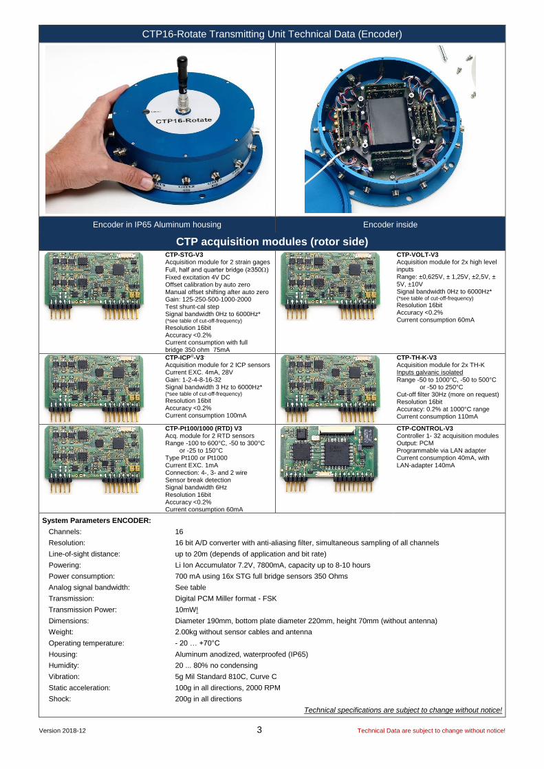
CTP16-Rotate Transmitting Unit Technical Data (Encoder)
Encoder in IP65 Aluminum housing Encoder inside
CTP acquisition modules (rotor side)
CTP-STG-V3 Acquisition module for 2 strain gages
Full, half and quarter bridge (≥350)
Fixed excitation 4V DC Offset calibration by auto zero Manual offset shifting after auto zero Gain: 125-250-500-1000-2000 Test shunt-cal step Signal bandwidth 0Hz to 6000Hz* (*see table of cut-off-frequency)
Resolution 16bit Accuracy <0.2% Current consumption with full bridge 350 ohm 75mA
CTP-VOLT-V3 Acquisition module for 2x high level inputs Range: ±0,625V, ± 1,25V, ±2,5V, ± 5V, ±10V Signal bandwidth 0Hz to 6000Hz* (*see table of cut-off-frequency)
Resolution 16bit Accuracy <0.2% Current consumption 60mA
CTP-ICP®-V3-
Acquisition module for 2 ICP sensors Current EXC. 4mA, 28V Gain: 1-2-4-8-16-32 Signal bandwidth 3 Hz to 6000Hz* (*see table of cut-off-frequency)
Resolution 16bit Accuracy <0.2% Current consumption 100mA
CTP-TH-K-V3 Acquisition module for 2x TH-K Inputs galvanic isolated Range -50 to 1000°C, -50 to 500°C or -50 to 250°C Cut-off filter 30Hz (more on request) Resolution 16bit Accuracy: 0.2% at 1000°C range Current consumption 110mA
CTP-Pt100/1000 (RTD) V3 Acq. module for 2 RTD sensors Range -100 to 600°C, -50 to 300°C or -25 to 150°C Type Pt100 or Pt1000 Current EXC. 1mA Connection: 4-, 3- and 2 wire Sensor break detection Signal bandwidth 6Hz Resolution 16bit Accuracy <0.2% Current consumption 60mA
CTP-CONTROL-V3 Controller 1- 32 acquisition modules Output: PCM Programmable via LAN adapter Current consumption 40mA, with LAN-adapter 140mA
System Parameters ENCODER:
Channels: 16
Resolution: 16 bit A/D converter with anti-aliasing filter, simultaneous sampling of all channels
Line-of-sight distance: up to 20m (depends of application and bit rate)
Powering: Li Ion Accumulator 7.2V, 7800mA, capacity up to 8-10 hours
Power consumption: 700 mA using 16x STG full bridge sensors 350 Ohms
Analog signal bandwidth: See table
Transmission: Digital PCM Miller format - FSK
Transmission Power: 10mW!
Dimensions: Diameter 190mm, bottom plate diameter 220mm, height 70mm (without antenna)
Weight: 2.00kg without sensor cables and antenna
Operating temperature: - 20 … +70°C
Housing: Aluminum anodized, waterproofed (IP65)
Humidity: 20 ... 80% no condensing
Vibration: 5g Mil Standard 810C, Curve C
Static acceleration: 100g in all directions, 2000 RPM
Shock: 200g in all directions
Technical specifications are subject to change without notice!

Version 2018-12 4 Technical Data are subject to change without notice!
CTP-DEC16 Receiver unit for max 16 Channels output via 37 pol. Sub D (radio transmission version with diversity receiver 312.5 … 1250kbit)
Plug-side
Optional BNC16 Box. Connect on 37pol Sub-D
CTP –DEC16 System Parameters:
Channel: 16 x +/-10V analog outputs via Sub-D male socket
Resolution: 16 bit D/A converter, with smoothing filter
Power supply input: 10-30 VDC, power consumption <24 Watt
Transmission: Digital PCM Miller Format – FSK,
Dimensions: 205 x 105 x 65mm
Weight: 1.25 kg without cables and antenna
Overall system accuracy between encoder input and decoder output: +/-0.25% without sensor influences
Environmental
Operating: -20 … +70°C
Humidity: 20 ... 80% not condensing
Vibration: 5g
Static acceleration: 10g in all directions
Shock: 100g in all directions
Front side view Rear side view
Female 37 pole Sub-D for analog signal output, CH 1 to 16
Transmission error LED
Fuse of powering defect LED
Power Switch
PCM out for IP-LAN-Interface (Opt.) (Option)
7-pole female TUCHEL connector for power supply input (10–30V DC)
SMA antenna connector with active LED of antenna (diversity)
Auto Zero LED Bright on, if analog output
is over 60mV
Low Pwr LED ON = BATT empty!
HF –Field strength display

Version 2018-12 5 Technical Data are subject to change without notice!
CTP-DEC16 Receiver unit for max 16 Channels output via 37 pol. Sub D (radio transmission version via quad receiver for 2500kbit and 5000kbit)
Plug-side
Optional BNC16 Box. Connect on 37pol Sub-D
CTP - DEC16 System Parameters:
Channels: 16 x +/-10V analog outputs via Sub-D male socket
Resolution: 16 bit D/A converter, with smoothing filter
Power supply input: 10-30 VDC, power consumption <24 Watt
Analog signal bandwidth: see frequency table
Transmission: Digital PCM Format
Dimension: 205 x 105 x 65mm
Weight: 1.00kg without cables and antenna
Overall system accuracy between encoder input and decoder output: +/-0.2% without sensor influences
Environmental
Operating: -20 … +70°C
Humidity: 20 ... 80% not condensing
Vibration: 5g
Static acceleration: 10g in all directions
Shock: 100g in all directions
Front side view Rear side view
Female 37 pole Sub-D for analog signal output, CH 1 to 16
Transmission error LED
Fuse of powering defect LED
Power Switch
PCM IN coming from
HF-BOX 7-pole female TUCHEL connector for power supply input (10–30V DC)
Low Pwr LED ON = BATT empty!
Power ON LED
GND cable to ground the housing

Version 2018-12 6 Technical Data are subject to change without notice!
CTP-DEC16 Receiver unit for max 16 Channels output via 37 pol. Sub D (radio transmission version via quad receiver for 2500kbit and 5000kbit)
HF BOX Quad System Parameters:
HF receivers 4
Antenna connection SMA
Output PCM
Power supply input: 10-30 VDC, power consumption <24 Watt
Dimensions: 205 x 105 x 65mm
Weight: 1.05 kg without cables and antenna
Environmental
Operating: -20 … +70°C
Humidity: 20 ... 80% not condensing
Vibration: 5g
Static acceleration: 10g in all directions
Shock: 100g in all directions
Active DATA LED, up to 2 receivers can be active! If a fault data is identified, it will switch automatically to a valid data from other receiver
4x SMA inputs for RX antenna
7-pole female TUCHEL connector for power supply input (10–30V DC)
PCM OUT Pin 1 ----- Pin 2 = PCM + (pink wire) Pin 3 = PCM -- (blue wire) Pin 4/5 = common GND & shield (black/green) Pin 6 -----
Power Switch
4x HF Level display
PCM/ DATA cable Length 0.5m standard (up to 25m on request)
Transmission error LED
Fuse of powering defect LED
GND cable to ground the housing


![ZAWANI AMIRAH BINTI RASID - eprints.utm.myeprints.utm.my/id/eprint/48737/25/ZawaniAmirahRasidMFKE2015.pdf · Kekurangan sumber bahan mentah ... water and diesel or oil [8]. Among](https://img.dokumen.tips/doc/110x75/5cdf638788c99399558c79f7/zawani-amirah-binti-rasid-kekurangan-sumber-bahan-mentah-water-and-diesel.jpg)


