Embed Size (px)
Citation preview

CHAPTER 1
Getting to KnowAutoCAD� Opening a new drawing
� Getting familiar with the AutoCAD and AutoCAD LTgraphics windows
� Modifying the display
� Displaying and arranging AutoCAD tools
260586c01.qxd 3/27/08 3:03 PM Page 1
COPYRIG
HTED M
ATERIAL

Your introduction to AutoCAD and AutoCAD LT begins with a tour of theuser interfaces of the two programs. In this chapter, you’ll also learn howto use some tools that help you control their appearance and how to findand start commands. For the material covered in this chapter, the two
applications are almost identical in appearance. Therefore, as you tour AutoCAD,I’ll point out any differences between AutoCAD and AutoCAD LT. In general, LTis a 2D program, so it doesn’t have most of the 3D features that come with Auto-CAD, such as solids modeling and rendering. The AutoLISP programming lan-guage found in AutoCAD is also absent from LT, as is the Action Recorder. Theother differences are minor. As mentioned in this book’s introduction, when Isay AutoCAD, I mean both AutoCAD and AutoCAD LT. I’ll also specifically refer toAutoCAD LT as LT throughout this chapter and the rest of the book. StartingAutoCAD is the first task at hand.
Starting AutoCADIf you installed AutoCAD using the default settings for the location of the programfiles, start the program by choosing Start ➣ Programs ➣ Autodesk ➣ AutoCAD2009 ➣ AutoCAD 2009 or by choosing Start ➣ Programs ➣ Autodesk ➣ AutoCADLT 2009 ➣ AutoCAD LT 2009, depending on your program. (This command pathmight vary depending on the Windows scheme you are using.) You can also findand click the AutoCAD 2009 icon or the AutoCAD LT 2009 icon on your desktop.
Exploring the New Features WorkshopThe New Features Workshop welcome screen opens when you first start Auto-CAD and leads to several animated demonstrations and explanations of the newfeatures included in the latest release of AutoCAD (see Figure 1.1). This is aquick and easy way to see how AutoCAD 2009 has improved over AutoCAD 2008and which tools you can use to augment any skills you already have. ChoosingMaybe Later on the left side of the dialog box causes it to reappear every timeyou start AutoCAD. Choosing the No, Don’t Show This To Me Again option dis-misses the dialog box indefinitely. If you chose that option, you must then accessthe New Features Workshop through the Help option in the Menu Browser, themenu system that you access by clicking on the large red A in the top-left cornerof the AutoCAD user interface.
Selecting the Yes radio button on the left side of the dialog box opens the NewFeatures Workshop dialog box (see Figure 1.2). Here, you navigate and select thefeature you want to investigate in the left pane and observe the selection in theright pane. The drop-down list in the upper-left corner provides access to theNew Features Workshops for other Autodesk products installed on your system.
C h a p t e r 1 • G e t t i n g t o K n o w A u t o C A D2
260586c01.qxd 3/27/08 3:03 PM Page 2
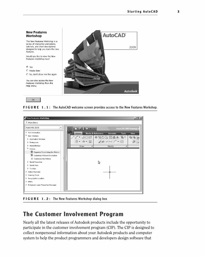
F I G U R E 1 . 1 : The AutoCAD welcome screen provides access to the New Features Workshop.
F I G U R E 1 . 2 : The New Features Workshop dialog box
The Customer Involvement ProgramNearly all the latest releases of Autodesk products include the opportunity toparticipate in the customer involvement program (CIP). The CIP is designed tocollect nonpersonal information about your Autodesk products and computersystem to help the product programmers and developers design software that
S t a r t i n g A u t o C A D 3
260586c01.qxd 3/27/08 3:03 PM Page 3

best meets their customers’ needs. If you haven’t yet agreed or declined to par-ticipate, when you first start AutoCAD, the Customer Involvement Program dia-log box might prompt you to join.
Participation is strictly voluntary, and if you choose to participate, AutoCADwill periodically send a small file to Autodesk containing information such asyour software name and version, the commands you use, and your system con-figuration information. An Internet connection is required, and you must ensurethat your firewall settings don’t prevent the information from being transmitted.
Exploring the AutoCAD User InterfaceAfter bypassing the initial dialog boxes that AutoCAD provides, the programopens to display the AutoCAD user interface, also called the graphics window.AutoCAD provides many methods for creating and editing objects, changing theview of a drawing, or executing AutoCAD file maintenance or other utilities. InLT, your screen looks similar to Figure 1.3. For AutoCAD, your monitor displaysone of three workspaces:
� The 2D Drafting & Annotation workspace (shown in Figure 1.3)
� The AutoCAD Classic workspace
� For AutoCAD users only, the 3D Modeling workspace (see Figure 1.4)
You’ll be using the 2D Drafting and Annotation workspace for the first 15chapters in this book. In the final two chapters, you’ll switch to the 3D Model-ing workspace, but for now, you need to get your AutoCAD user interface tolook like Figure 1.3.
N O T E The figures and graphics is this book show the drawing area ofthe AutoCAD user interface with a white background, but the default, and pre-ferred, method is to use a black background to reduce eyestrain. The colorchoice in the book is simply for readability.
C h a p t e r 1 • G e t t i n g t o K n o w A u t o C A D4
�
AutoCAD and LToffer numerous dia-log boxes with vari-ous combinations ofbuttons and textboxes.You’ll learnmany of their func-tions as you progressthrough the book.
260586c01.qxd 3/27/08 3:03 PM Page 4

F I G U R E 1 . 3 : The AutoCAD graphics window using the 2D Drafting & Annotation workspace
F I G U R E 1 . 4 : The AutoCAD graphics window using the 3D Modeling workspace
ViewCubeTool Palettes
S t a r t i n g A u t o C A D 5
260586c01.qxd 3/27/08 3:03 PM Page 5

If your screen looks like Figure 1.4 or isn’t at all like Figure 1.3, you need tomake a few changes:
1. Click the Workspace Switching button in the status bar and choose2D Drafting & Annotation. Alternately, you can choose Tools ➣
Workspaces ➣ 2D Drafting & Annotation.
2. The 2D Drafting & Annotation workspace may display the tool paletteson the screen. If the palettes are displayed, you need to turn them offfor now by clicking the X in the upper-right corner. Your workspacemight have different palettes displayed than those shown in Figure 1.5.If other palettes are still visible, click the X in the upper-right or upper-left corner of each palette to close them.
F I G U R E 1 . 5 : The tool palettes
3. The large area in the middle of the screen is called the drawing area.It might need adjusting. Enter visualstyles↵ to open the Visual StylesManager, and then click the 2D Wireframe option (see Figure 1.6).Close the Visual Styles Manager.
C h a p t e r 1 • G e t t i n g t o K n o w A u t o C A D6
�
LT users can skipstep 3 and move onto step 4
260586c01.qxd 3/27/08 3:03 PM Page 6

F I G U R E 1 . 6 : Selecting the 2D Wireframe visual style
4. Enter plan↵ and then world↵ or click the World option in the pop-upmenu if it appears.
If dots appear in the drawing area, the grid is turned on.
5. Move the cursor to the left side of the status bar at the bottom of thescreen, and click the Grid Display button so it’s in the off (unpushed)position and the dots disappear. Be sure all the other readout buttonsexcept Dynamic Input are in their off (unpushed) positions. You canpause your cursor over each button to reveal its name in a tooltip.
Your screen should look similar enough to Figure 1.3 to continue.
S t a r t i n g A u t o C A D 7
260586c01.qxd 3/27/08 3:03 PM Page 7

Introducing the AutoCAD Graphics WindowAt the top of the graphics window sit the Ribbon, the Quick Access toolbar to theleft, and the InfoCenter and related tools on the right.
The title bar is analogous to the title bar in any Windows program. It containsthe program name (AutoCAD or AutoCAD LT) and the title of the current draw-ing with its path, as long as any drawing other than the default Drawingn.dwg isopen. Below the title bar is the Ribbon, where you’ll find most of the AutoCADcommands and tools needed to complete any drawing task. Related tasks arefound under the different tabs, which are further segmented into panels contain-ing similar tools.
To the far right of the title bar are the InfoCenter, Communications Center,Favorites, and Help buttons. You can enter a question in the field to the left of theInfoCenter button to quickly access information from the Help system throughthe InfoCenter’s drop-down panel. With the Communications Center, you candetermine what type of information, such as software updates, product support,or RSS feeds, Autodesk sends directly to your system. With the Favorites tool,you can define a list of help or informational topics that can be quickly accessedwhenever you need them. The Help button is a direct link to the AutoCAD helpsystem.
The blank middle section of the screen is called the drawing area. Notice themovable crosshair cursor. The crosshairs on your cursor might extend com-pletely across the screen. Later in this chapter, I will show you how to modify thelength of the crosshairs as well as make a few other changes.
Notice the little box at the intersection of the two crosshair lines. This is oneof several forms of the AutoCAD cursor. When you move the cursor off the draw-ing area, it changes to the standard Windows pointing arrow. As you begin using
Quick Access Toolbar
C h a p t e r 1 • G e t t i n g t o K n o w A u t o C A D8
�
The title bar andmenu bar at the topof the LT screen areidentical to those inAutoCAD except thatAutoCAD LT appearsin the title bar ratherthan AutoCAD.
260586c01.qxd 3/27/08 3:03 PM Page 8

commands, it will take on other forms, depending on which step of a commandyou’re performing.
The icon with a double arrow in the lower-left corner of the drawing area is theUCS icon (UCS stands for user coordinate system). It indicates the positivedirection for the x- and y-axes. You won’t need it for most of the chapters in thisbook, so you’ll learn how to turn it off in Chapter 3.
Below the drawing area is the Command window.
When you enter commands in addition to using the Ribbon or pop-up menus,the Command window is where you tell the program what to do and where theprogram tells you what’s happening. It’s an important area, and you’ll need tolearn how it works in detail. Four lines of text should be visible. You’ll learn howto increase the number of visible lines later in this chapter in the section “Work-ing in the Command Window.” When the Dynamic Input feature is active, muchof the Command window information is displayed at the cursor as well.
Below the Command window is the status bar.
On the left end of the status bar, you’ll see a coordinate readout window. In themiddle are 10 buttons (LT has only 9) that activate various drawing modes. It’simportant to learn about the coordinate system and most of these drawing aids(Snap Mode, Grid Display, Ortho Mode, Object Snap, etc) early on as you learn todraw in AutoCAD. They will help you create neat and accurate drawings. PolarTracking and Object Snap Tracking are advanced drawing tools and will be intro-duced in Chapter 5. Dynamic UCS stands for Dynamic User Coordinate System; it’s
I n t r o d u c i n g t h e A u t o C A D G r a p h i c s Wi n d o w 9
260586c01.qxd 3/27/08 3:03 PM Page 9

used in 3D drawings. The Dynamic Input button is an on/off toggle that activates orsuppresses the dynamic display of information next to the crosshair cursor whenit’s in the drawing area. For now, keep it in the on (pushed) mode. The Show/HideLineweight button toggles the display of lineweights (discussed in Chapter 14) inthe drawing area. When active, the Quick Properties tool displays the most com-mon properties for the selected object(s) in a dialog box where they can be edited. Ifyou prefer text-based buttons rather than icons, you can right-click on any of thetools mentioned here and uncheck the Use Icons option.
At the right side of the status bar are tools for controlling the appear-ance of annotation objects in AutoCAD, tools for navigating in the draw-
ing area and controlling the display, and tools to control access to otherdrawings or features within the current drawing. The padlock icon controlswhich types of toolbars and windows are locked in their current positions onthe screen. Leave it in the unlocked mode for now.
To conclude this quick introduction to the various parts of the graphics window, Ineed to mention a couple of items that might be visible on your screen. You mighthave scroll bars below and to the right of the drawing area; although these can beuseful, they can take up precious space in the drawing area. They won’t be of any usewhile working your way through this book, so I suggest you remove them for now.
To remove these features temporarily, follow these steps:
1. Enter options↵ to open the Options dialog box (shown in Figure 1.7). Ithas 10 tabs (LT has only 8) across the top that act like tabs on file folders.
F I G U R E 1 . 7 : The Options dialog box
C h a p t e r 1 • G e t t i n g t o K n o w A u t o C A D1 0
260586c01.qxd 3/27/08 3:03 PM Page 10

2. Click the Display tab, which is shown in Figure 1.8. Focus on theWindow Elements section. If scroll bars are visible on the lower andright edges of the drawing area, the Display Scroll Bars In DrawingWindow check box will be selected.
F I G U R E 1 . 8 : The Options dialog box open at the Display tab
3. Click the check box to turn off the scroll bars. Also be sure the checkboxes for Display Screen Menu and, in the Layout Elements section,Display Layout And Model Tabs are not selected. Don’t click the OKbutton yet.
Another display setting that you might want to change at this point controlsthe color of the cursor and the drawing area background. The illustrations inthis book show a white background and black crosshair cursor, but you’re proba-bly seeing the AutoCAD default, which features a black background and a whitecrosshair cursor. If you want to change the colors, follow these steps:
1. In the Window Elements area of the Display tab, click the Colors but-ton to open the Drawing Window Colors dialog box (see Figure 1.9).In the upper-left corner of the dialog box, in the Context list box, 2DModel Space should be selected. If it’s not, select it.
I n t r o d u c i n g t h e A u t o C A D G r a p h i c s Wi n d o w 1 1
�
LT doesn’t have theScreen menu, so the option to turn it off isn’t on LT’sDisplay tab.
260586c01.qxd 3/27/08 3:03 PM Page 11

F I G U R E 1 . 9 : The Drawing Window Colors dialog box
N O T E The screen-captured images in this book are taken from AutoCADsessions using the Dark Color Scheme.You can set the Color Scheme at the topof the Window Elements area and choose either the Light or Dark scheme.
2. Move to the Color drop-down list, which is in the upper-right corner.If your drawing area background is currently white, a square followedby the word White is displayed. Open the Color drop-down list, andselect Black (or the background color you want). The drawing areawill now be that color, and the cursor color will change to white, asshown in the Preview window below.
3. Click the Apply & Close button to close the Drawing Window Colorsdialog box. The background and cursor colors change.
4. If you want to change the length of the lines of your crosshair cursor,go to the lower-right corner of the Display tab (the middle of the rightside for LT), and move the slider to change the Crosshair Size setting.The crosshair length changes as a percentage of the drawing area.
5. Click OK to apply any remaining changes and close the Options dia-log box.
C h a p t e r 1 • G e t t i n g t o K n o w A u t o C A D1 2
260586c01.qxd 3/27/08 3:03 PM Page 12

T I P If you choose a color other than black as the drawing area back-ground color, the color of the crosshair cursor remains the same as it was. Tochange the crosshair color, in the Drawing Window Colors dialog box, go tothe Interface Element list box, and select Crosshairs. Then, select a color fromthe Color drop-down list.
Working in the Command WindowJust below the drawing area is the Command window. This window is separatefrom the drawing area and behaves like a Windows window—that is, you can dragit to a different place on the screen and resize it, although I don’t recommend youdo this at first. If you currently have fewer than four lines of text in the window,you should increase the window’s vertical size. To do so, move the cursor to thehorizontal boundary between the drawing area and the Command window until itchanges to an up-and-down arrow broken by two parallel horizontal lines.
Hold down the left mouse button, drag the cursor up by approximately theamount that one or two lines of text would take up, and then release the mousebutton. You should see more lines of text, but you might have to try this a fewtimes to display exactly four lines. A horizontal line will separate the top twolines of text from the bottom line of text. When you close the program, AutoCADwill save the new settings. The next time you start AutoCAD, the Command win-dow will display four lines of text.
The Command window is where you give information to AutoCAD and whereAutoCAD prompts you for the next step in executing a command. It’s good prac-tice to keep an eye on the Command window as you work on your drawing. Manyerrors can occur when you don’t check it frequently. If the Dynamic Input but-ton on the status bar is in the on position, some of the information in the Com-mand window will appear in the drawing area next to the cursor. I’ll cover thisfeature when you start drawing.
Before you begin to draw in the next chapter, take a close look at the Ribbon,Menu Browser, toolbars, and keyboard controls.
N O T E In many cases, you can start AutoCAD commands in a number ofways: from the Ribbon, the Menu Browser, from the Command window, andfrom menus that appear when you right-click. When you get used to drawingwith AutoCAD, you’ll learn some shortcuts that start commands quickly, andyou’ll find the way that is most comfortable for you.
Wo r k i n g i n t h e C o m m a n d Wi n d o w 1 3
260586c01.qxd 3/27/08 3:03 PM Page 13

Using the RibbonNew to AutoCAD 2009 is the Ribbon, a consolidated location for nearly all the Auto-CAD tools in the form of easily recognizable buttons. A set of tabs delineates the dif-ferent collections of tools by their purposes: creating and editing objects, addingnotes and dimensions, sending the drawing to a printer or plotter, and so on.
Displaying the Ribbon ToolsThe Ribbon self-adjusts according to the width of the AutoCAD window. The pan-els have the most commonly used command as a button, larger than the others,centered on the left side (see the top of Figure 1.10). When the width is too nar-row to fully display each panel, the panels will begin to collapse first by replacingthe large buttons with smaller buttons and then by replacing the panels with asingle button bearing the name of the panel. The collapsed panel’s tools are dis-played by clicking this single button, as shown at the bottom of Figure 1.10.
F I G U R E 1 . 1 0 : The Ribbon fully displaying all panels (top) and with partially and com-pletely collapsed panels (bottom)
Collapsing, Moving, and Hiding the Ribbon
Available drawing area is always at a premium, and you can regain someof it by collapsing the Ribbon. When you click the Minimize button to
the right of the Ribbon tabs once, the panels are collapsed vertically and onlyshow their titles. Clicking it a second time collapses the Ribbon further untilonly the tabs show. When the Ribbon is in either of these states, you can expandany panel or tab by clicking its visible panel or tab name. Clicking the Minimizebutton a third time returns the Ribbon to its default state.
C h a p t e r 1 • G e t t i n g t o K n o w A u t o C A D1 4
260586c01.qxd 3/27/08 3:03 PM Page 14

The Ribbon’s default location is at the top of the screen, but it can be undocked,or floating over the drawing area, or it can be moved to a second monitor ordocked on either side of the drawing area. To undock the Ribbon, right-click tothe right of the tab names and choose Undock from the pop-up menu.
The Ribbon detaches from the top of the drawing area and floats on the screenas shown in Figure 1.11. To dock it, click the title bar on the side of the floatingRibbon and drag it to the side or the top of the drawing area. Experiment withdetaching the Ribbon, but when you are finished, dock it back at the top so thatyou can more easily follow the graphics in this book.
F I G U R E 1 . 1 1 : The Ribbon after undocking it from the top of the drawing area
If you don’t want the Ribbon at all, you can turn it off by right-clicking to theright of the Ribbon tabs and choosing Close. To turn it on, enter ribbon↵. You’lluse the Ribbon throughout this book.
Using the Ribbon ToolsEach panel contains tools from a related family of functions. For example, all thecommon tools for editing objects in the drawing area are consolidated in theModify panel. When more tools are available than will fit on the panel, an arrowis displayed on the panel’s title bar. Clicking the title bar expands the panel and
U s i n g t h e R i b b o n 1 5
260586c01.qxd 3/27/08 3:03 PM Page 15

exposes the additional tools. Follow these steps to learn how the Ribbon toolswork and how they display information.
1. Click the Home tab on the Ribbon to expose the Home tab’s panels.
2. Move the cursor over the Modify panel. The panel and panel title barchange from light gray to white to indicate that that panel has theprogram’s focus.
3. Pause the cursor over the Explode button to expose the button’stooltip as shown at the top of Figure 1.12. This tooltip displays thename of the tool, a brief description of its function, the command-line equivalent of clicking the tool, and instructions to click the F1key to open the AutoCAD Help file to the current tool’s Help page.
F I G U R E 1 . 1 2 : The tooltip for the Explode command (top) and theextended tooltip (bottom)
4. After a few seconds of hovering over the Explode button, the tooltipexpands to display the extended tooltip (see the bottom of Figure 1.12)with a more complete description.
5. Pause the cursor over the Copy button in the Modify panel. This time,after a few seconds, the tooltip is replaced with a cue card, as shownin Figure 1.13, instead of an extended tooltip. Cue cards show thestep-by-step implementation of the tool.
C h a p t e r 1 • G e t t i n g t o K n o w A u t o C A D1 6
260586c01.qxd 3/27/08 3:03 PM Page 16

F I G U R E 1 . 1 3 : The cue card for the Copy tool
6. Click the Modify panel’s title bar to expand the panels and expose allof the Modify tools.
7. Often, you may find yourself returning to the same tool on an expandedRibbon panel. When that happens, you can pin the panel open by click-ing the pushpin-shaped button in the bottom-right corner. When thepanel is pinned open, it remains open even when the cursor is not hov-ering over it.
8. Click the button again to unpin the panel and then move the cursoroff the panel to collapse it.
Customizing the RibbonYou can customize each panel of the Ribbon, and you can build your own customtabs and panels to display only the buttons you use frequently. You can even designyour own buttons for commands that aren’t already represented by buttons on thetoolbars. These activities are for more advanced users, however, and aren’t coveredin this book. To find out more about how to customize toolbars, see MasteringAutoCAD 2009 and AutoCAD LT 2009 by George Omura (Wiley, 2008).
U s i n g t h e R i b b o n 1 7
260586c01.qxd 3/27/08 3:03 PM Page 17

Using the Menu BrowserThe Menu Browser has replaced the traditional row of drop-down menus thatreside at the top of many programs. The menus now project from the upper-leftcorner of the AutoCAD Window and cover the drawing area, and any open dialogboxes, only when the Menu Browser is open.
1. Click the large, red A button in the top-left corner of the AutoCADwindow to open the Menu Browser.
2. The left pane of the Menu Browser displays the different menus. Hov-ering over a menu displays the commands and submenus in the rightpane, as shown in Figure 1.14.
F I G U R E 1 . 1 4 : The Menu Browser
C h a p t e r 1 • G e t t i n g t o K n o w A u t o C A D1 8
260586c01.qxd 3/27/08 3:03 PM Page 18

3. Submenus are identified by the pale, right-facing arrows to the left oftheir names. Click this arrow, or the name of a submenu, to expand itand display the tools. Click in the same location again to collapse thesubmenu.
Opening a Drawing with the Menu BrowserThe Menu Browser offers a quick method for opening drawings. You can evensee a thumbnail preview of the drawings and arrange drawings that you fre-quently edit so that they are easily accessible. Here’s how:
1. To open a new AutoCAD file from the Menu Browser, click File ➣ New.
This opens the Select Template dialog box, where you select a tem-plate to base the new drawing on. Opening a file with a template iscovered in Chapter 2.
2. To open an existing file from the Menu Browser, click File ➣ Open.
This opens the Select File dialog box where you can navigate to andselect the desired drawing file.
T I P You can open new or existing files using the QNew or Open buttonsin the Quick Access toolbar. Existing drawings can also be opened by drag-ging them from a Windows Explorer window to the AutoCAD title bar.
U s i n g t h e M e n u B r o w s e r 1 9
260586c01.qxd 3/27/08 3:03 PM Page 19

3. To open a file that you’ve worked on recently, hover over the RecentDocuments option in the lower-left corner of the Menu Browser. Thisdisplays the most recent files opened in AutoCAD in the right pane, asshown in Figure 1.15.
F I G U R E 1 . 1 5 : Displaying the recent documents in the Menu Browser
The Recent Documents list is updated whenever a new drawing isopened. Clicking the pushpin icon next to a drawing name, in theright pane, pins that drawing to its current location in the list. Pinneddocuments don’t scroll off the list when newer files are opened.
4. Hover over a file name in the right pane to display a thumbnail pre-view of the drawing and additional information, including the draw-ing location and AutoCAD drawing format.
C h a p t e r 1 • G e t t i n g t o K n o w A u t o C A D2 0
260586c01.qxd 3/27/08 3:03 PM Page 20

N O T E AutoCAD 2009 drawing files use the same drawing format asAutoCAD versions 2008 and 2007. This means that the files are compatiblebetween versions without requiring any type of conversion.
Switching Between Open DrawingsAs in many programs, you can have multiple drawing files open in the samesession of AutoCAD. Each drawing is stacked behind the drawings in front of it.There are several ways to switch between the open file including using the MenuBrowser, as shown here.
1. Start or open two or more AutoCAD files.
2. Open the Menu Browser and then hover over the Open Documentsoption in the lower-left corner. The open drawings are displayed inthe right panel, and the current drawing is marked with a blue dot tothe left of its name, as shown in Figure 1.16.
F I G U R E 1 . 1 6 : Displaying the open drawings in the Menu Browser
3. Click on any drawing to bring it to the front of the AutoCAD window.
U s i n g t h e M e n u B r o w s e r 2 1
260586c01.qxd 3/27/08 3:03 PM Page 21

Another option for switching between open drawings is to click theQuick View Drawings button in the status bar. This displays thumb-nails for the open drawings, and you can click any thumbnail to makethat drawing active.
Using the Drop-Down MenusIf you prefer to use drop-down menus, they’re still available in AutoCAD 2009,although they are turned off by default in the 2D Drafting & Annotation and 3DModeling workspaces. You can display them by switching to the AutoCAD Classicworkspace, by right-clicking on the Quick Access toolbar and choosing ShowMenu Bar, or by entering menubar↵ 1↵. The menu bar isn’t used in the exer-cises in this book, but I’ll cover the menus here in case you want to use them inthe future.
The left end of the menu bar, just below the title bar (see Figure 1.17), consistsof an icon and 12 (11 if you don’t have the Express Tools installed or are using LT)menus. Click any of these to display a drop-down menu. The icon and the File andEdit menus are included with all Windows-compliant applications, although theyare somewhat customized to work with AutoCAD. The drop-down menu associ-ated with the icon contains commands to control the appearance and position ofthe drawing area.
F I G U R E 1 . 1 7 : The AutoCAD user interface showing the menu bar
Commands in the File menu are for opening and saving new and existing draw-ing files, printing, exporting files to another application, choosing basic utilityoptions, and exiting the application. The Edit menu contains the Undo and Redocommands, the Cut and Paste tools, and options for creating links between Auto-CAD files and other files. The Help menu works like most Windows Help menusand contains a couple of AutoCAD-specific entries as well, including some onlineresources and a link to the New Features Workshop.
C h a p t e r 1 • G e t t i n g t o K n o w A u t o C A D2 2
260586c01.qxd 3/27/08 3:03 PM Page 22

The other eight (or nine) menus contain the most frequently used AutoCADcommands. You’ll find that if you master the logic of how the commands areorganized by menu, you can quickly find the command you want. Here is a shortdescription of each of the other AutoCAD drop-down menus:
View Contains tools for controlling the display of your drawing file.
Insert Contains commands for placing drawings and images or parts of theminside other drawings.
Format Contains commands for setting up the general parameters for a newdrawing or changing the entities in a current drawing.
Tools Contains special tools for use while you’re working on the current draw-ing, such as those for finding the length of a line or for running a special macro.
Draw Contains commands for creating new objects (such as lines or circles) onthe screen.
Dimension Contains commands for dimensioning and annotating a drawing.
Modify Contains commands for changing existing objects in the drawing.
Window Contains commands for displaying currently open drawing windowsand lists currently open drawing files.
Express Contains a library of productivity tools that cover a wide range ofAutoCAD functions. Express Tools are widely used but unsupported directly byAutodesk. They might or might not be installed on your computer.
You can turn off the menu bar by right-clicking on the Quick Access toolbarand choosing Show Menu Bar or by entering menubar↵ 0↵.
Using the ToolbarsThe AutoCAD toolbars have essentially been replaced by the Ribbon, so I’ll onlytouch on them briefly here. Toolbars, like the Ribbon panels, are collections oftools grouped by similar tasks. Like the Ribbon itself, any toolbar can be dis-played or hidden without affecting the others, and they can all be docked to aside or the top of the drawing area or float freely. To display a toolbar, right-
U s i n g t h e To o l b a r s 2 3
260586c01.qxd 3/27/08 3:03 PM Page 23

click on the Quick Access toolbar, click Toolbars, click a toolbar category, andthen click the toolbar that you want to open.
Take a few minutes to explore the available toolbars, and then open the Stan-dard toolbar from the AutoCAD or AutoCAD LT category.
The icons on the AutoCAD toolbars look like flat images and don’t appear asraised buttons until you point to them. The Standard toolbar has 25 icons, andthey are arranged into seven logical groups. The icons on the left half of theStandard toolbar are mostly for commands used in all Windows-compatibleapplications, so you might be familiar with them. The icons on the right half ofthe Standard toolbar are AutoCAD commands that you use during your regulardrawing activities. You can use these commands to take care of a number oftasks, including the following:
� Changing the view of the drawing on the screen
� Changing the properties of an object, such as color or linetype
� Borrowing parts of an unopened drawing to use in your currentdrawing
� Displaying a set of palettes that contain objects you can use in yourdrawing
Accessing the Toolbar Fly-Out MenusNotice that one icon on the Standard toolbar has a little triangular arrow in thelower-right corner. This arrow indicates that clicking this icon displays more thanone command. Follow these steps to see how this special icon works:
1. Move the cursor to the Standard toolbar, and point to the icon thathas a magnifying glass with a rectangle in it.
2. Rest the arrow on the button for a moment without clicking to dis-play the tooltip. Notice the small arrow in the lower-right corner ofthe icon. This is the multiple-command arrow mentioned earlier.
C h a p t e r 1 • G e t t i n g t o K n o w A u t o C A D2 4
�
LT has only 23Standard toolbarbuttons. It doesn’thave the Sheet SetManager and BlockEditor buttonsbecause LT doesn’toffer these features.
260586c01.qxd 3/27/08 3:03 PM Page 24

3. Place the arrow cursor on the button, and hold down the left mousebutton. A column of nine buttons opens vertically below the originalbutton (see Figure 1.18). The top button in the column is a duplicateof the button you clicked. This column of buttons is called a toolbarfly-out menu. In this example, you’re working with the Zoom toolbarfly-out menu.
F I G U R E 1 . 1 8 : A toolbar fly-out menu
4. To dock a floating toolbar, click the grab bar and drag the toolbar toeither side of the drawing area or to just below the AutoCAD title barand release.
5. To detach a docked toolbar, click the grab bar and drag the toolbarinto the drawing area.
6. Close any open toolbars by undocking them then clicking the X inthe upper-right corner of each.
The toolbar fly-out menus are regular toolbars that have been attached toanother toolbar. AutoCAD has 38 toolbars in all, but only a few have fly-outmenus—the Zoom fly-out menu I just discussed and the Insert fly-out menu onthe Draw toolbar, for example.
U s i n g t h e To o l b a r s 2 5
�
Grab bars are the twolines at the left end ofa horizontal toolbaror at the top of a ver-tical one. They repre-sent the one place tograb a docked toolbarto move it.You canalso change a dockedtoolbar into a floatingtoolbar by double-clicking its grab bars.
260586c01.qxd 3/27/08 3:03 PM Page 25

N O T E LT has 27 toolbars compared with AutoCAD’s 38. The additionaltoolbars in AutoCAD are almost all for 3D and rendering tools.
WorkspacesYou haven’t been directed to make any significant changes to the workspace, butwhen you do, you can save this setup as a new workspace. Using this feature, youcan always return to your preferred layout by activating the saved layout. Followthese steps:
1. Click the Workspace Switching button on the right side of the statusbar and choose Save Current As. This opens the Save Workspace dia-log box.
2. Enter a name for the workspace and click Save. The dialog box closes,and you are returned you to your workspace. Until you change it orselect a different workspace, the new workspace setup will remain asit is now.
When you make changes to the new workspace—by adding a toolbar or chang-ing the background color of the drawing area—you can easily update the currentworkspace to accommodate those changes. Follow steps 1 and 2 previously, nam-ing the workspace again with the same name. You’ll get a warning window tellingyou that a workspace by that name already exists and asking you whether youwant the new arrangement to replace the old one. Click Yes.
Using the KeyboardThe keyboard is an important tool for entering data and commands. If you’re agood typist, you can gain speed in working with AutoCAD by learning how toenter commands from the keyboard. AutoCAD provides what are called aliaskeys—single keys or key combinations that start any of several frequently used
C h a p t e r 1 • G e t t i n g t o K n o w A u t o C A D2 6
260586c01.qxd 3/27/08 3:03 PM Page 26

commands. You can add more or change the existing aliases as you get morefamiliar with the program.
In addition to the alias keys, you can use several of the F keys (function keys)on the top row of the keyboard as two-way or three-way toggles to turn AutoCADfunctions on and off. Although buttons on the screen duplicate these functions(Snap, Grid, and so on), it’s sometimes faster to use the F keys.
While working in AutoCAD, you’ll need to enter a lot of data, such as dimen-sions and construction notes; answer questions with “yes” or “no,” and use thearrow keys. You’ll use the keyboard constantly. It might help to get into thehabit of keeping your left hand on the keyboard and your right hand on themouse if you’re right-handed, or the other way around if you’re left-handed.
Using the MouseYour mouse most likely has two buttons and a scroll wheel. So far in this chap-ter, you have used the left mouse button to choose menus, commands, andoptions, and you’ve held it down to drag menus, toolbars, and windows. The leftmouse button is the one you’ll be using most often, but you’ll also use the rightmouse button.
While drawing, you’ll use the right mouse button for the following threeoperations:
� To display a menu containing options relevant to the particular stepyou’re in at the moment
� To use in combination with the Shift or Ctrl key to display a menucontaining special drawing aids called object snaps
� To display a menu of toolbars when the pointer is on any icon of atoolbar that is currently open
If you have a three-button mouse, the middle button is usually programmedto display the Object Snap menu, instead of using the right button with theShift key. If you have a mouse with a scroll wheel, you can use the wheel in sev-eral ways to control the view of your drawing. I’ll cover those methods in subse-quent chapters.
AutoCAD makes extensive use of toolbars and the right-click menu feature.This makes your mouse an important input tool. The keyboard is necessary forinputting numeric data and text, and it has hot keys and aliases that can speedup your work; however, the mouse is the primary tool for selecting options andcontrolling toolbars.
U s i n g t h e M o u s e 2 7
260586c01.qxd 3/27/08 3:03 PM Page 27

The next chapter will familiarize you with a few basic commands that willenable you to draw a small diagram. If want to take a break and close AutoCAD,choose File ➣ Exit, and choose not to save the drawing.
Are You Experienced?
Now you can…
0 recognize the elements of the AutoCAD graphics window
0 understand how the Command window works and why it’simportant
0 start commands from the Ribbon
0 start commands from the command line
0 use the Menu Browser
0 display the drop-down menus
0 open and control the positioning of toolbars
0 save a workspace of your screen setup in AutoCAD
C h a p t e r 1 • G e t t i n g t o K n o w A u t o C A D2 8
260586c01.qxd 3/27/08 3:03 PM Page 28