Embed Size (px)
Citation preview
© 2012 Aspen Technology, Inc. All rights reserved
Getting Started with Aspen HYSYS Dynamics Solving safety and operability challenges
Dr. Glenn Dissinger,
Product Director, Aspen Technology
Hosted by:
Ron Beck,
Product Marketing, AspenTech
Optimizing Operations Webinar
Sept 5, 2012
© 2012 Aspen Technology, Inc. All rights reserved |
2
Ongoing Series of Technical Webinars Engineering Webinars for education and best practices
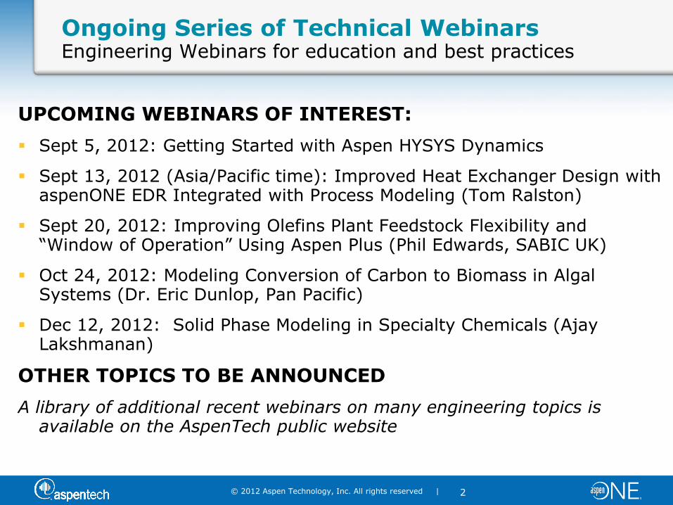
UPCOMING WEBINARS OF INTEREST:
Sept 5, 2012: Getting Started with Aspen HYSYS Dynamics
Sept 13, 2012 (Asia/Pacific time): Improved Heat Exchanger Design with aspenONE EDR Integrated with Process Modeling (Tom Ralston)
Sept 20, 2012: Improving Olefins Plant Feedstock Flexibility and “Window of Operation” Using Aspen Plus (Phil Edwards, SABIC UK)
Oct 24, 2012: Modeling Conversion of Carbon to Biomass in Algal Systems (Dr. Eric Dunlop, Pan Pacific)
Dec 12, 2012: Solid Phase Modeling in Specialty Chemicals (Ajay Lakshmanan)
OTHER TOPICS TO BE ANNOUNCED
A library of additional recent webinars on many engineering topics is available on the AspenTech public website

© 2012 Aspen Technology, Inc. All rights reserved |
3
Common Models & Data
aspenONE Integration
Support Manufacturing & Supply Chain
Conceptual Engineering
Basic Engineering
Detailed Engineering
aspenONE engineering Best-in-class engineering solutions in an integrated work flow
Aspen Simulation Workbook & Aspen Online Deployment
Aspen Petroleum Downstream & HYSYS Upstream
Aspen Equipment Design & Rating
Aspen Basic Engineering Aspen Capital
Cost Estimator (ACCE)
Aspen Plus Dynamics, ACM & Flare System & Energy Analyzer
Aspen Plus
Aspen HYSYS
Aspen Process Economic Analyzer (APEA)
Detailed Engineering
© 2012 Aspen Technology, Inc. All rights reserved |
4
Agenda
Introduction to Dynamic Simulation
– What Is It?
– Applications
Overview of HYSYS Dynamics
Demo – Transitioning a Steady-State Model to Dynamics
Q&A
© 2012 Aspen Technology, Inc. All rights reserved |
5
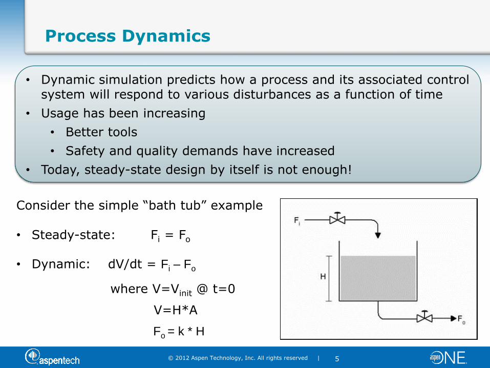
Process Dynamics
Consider the simple “bath tub” example • Steady-state: Fi = Fo
• Dynamic: dV/dt = Fi – Fo
where V=Vinit @ t=0
V=H*A
Fo = k * H
• Dynamic simulation predicts how a process and its associated control system will respond to various disturbances as a function of time
• Usage has been increasing
• Better tools
• Safety and quality demands have increased
• Today, steady-state design by itself is not enough!

© 2012 Aspen Technology, Inc. All rights reserved |
6
Applications of Dynamic Modeling & Simulation
Design / Analysis of Control Schemes
– Design the process and control system simultaneously
– Analyze and improve basic control strategies (e.g., fractionators, compressor surge, location of sensors, etc.)
– Pre-tune control loops
– Evaluate, develop and test APC scenarios (DMCplus)
Operability Engineering Studies
– Understand dynamic plant behavior, including upset propagation (e.g., slugging)
– Operability studies of highly-integrated processes
– Design / analysis of start-up, shutdown and process transition strategies
Hazard and Safety Studies
– Design / analysis of pressure relief and flare systems
– Safety studies
– Design / analysis of emergency shutdown systems
Operator Training
– DCS checkout
– Graphics functionality/operability of the operator consoles

© 2012 Aspen Technology, Inc. All rights reserved |
7
Agenda
Introduction to Dynamic Simulation
– What Is It?
– Applications and Success Stories
Overview of HYSYS Dynamics
Demo – Transitioning a Steady-State Model to Dynamics
Q&A

© 2012 Aspen Technology, Inc. All rights reserved |
8
What Does HYSYS Dynamics Offer?
Seamless transition from Steady State to Dynamic
Interactive environment
Rich choice between simple and detailed modeling
A comprehensive library of control and logical operations
Dynamics Assistant
© 2012 Aspen Technology, Inc. All rights reserved |
9
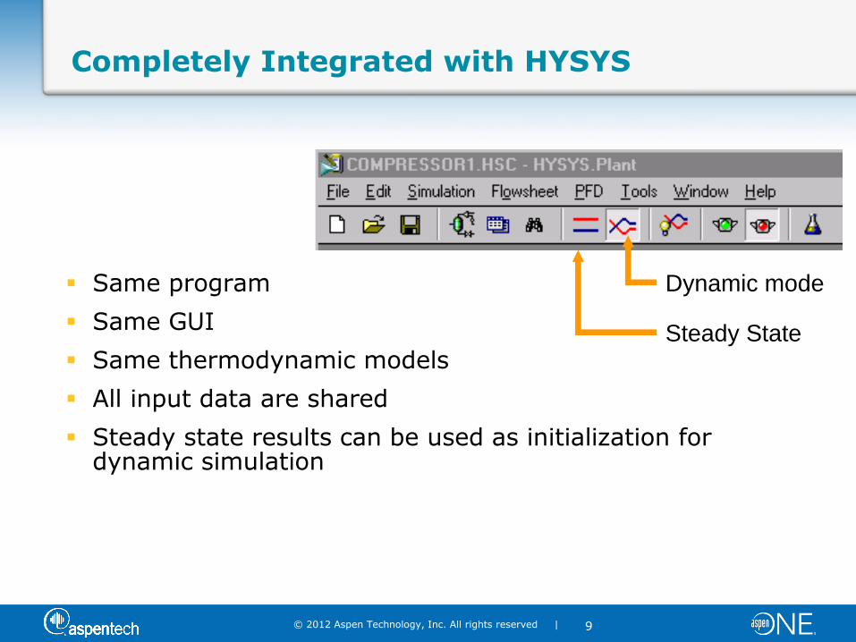
Steady State
Dynamic mode
Completely Integrated with HYSYS
Same program
Same GUI
Same thermodynamic models
All input data are shared
Steady state results can be used as initialization for dynamic simulation

© 2012 Aspen Technology, Inc. All rights reserved |
10
Rich choice between simple and detailed modeling options - Vessels
Simple Design Dynamics
A vessel with only the volume specified
Detailed Plant Dynamics
A vessel with
– Vessel elevation defined
– Nozzle positions defined
– Heat losses defined
– Entrainment modeling
– Level taps
or
© 2012 Aspen Technology, Inc. All rights reserved |
11
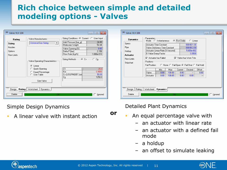
Rich choice between simple and detailed modeling options - Valves
Simple Design Dynamics
A linear valve with instant action
Detailed Plant Dynamics
An equal percentage valve with
– an actuator with linear rate
– an actuator with a defined fail mode
– a holdup
– an offset to simulate leaking
or
© 2012 Aspen Technology, Inc. All rights reserved |
12
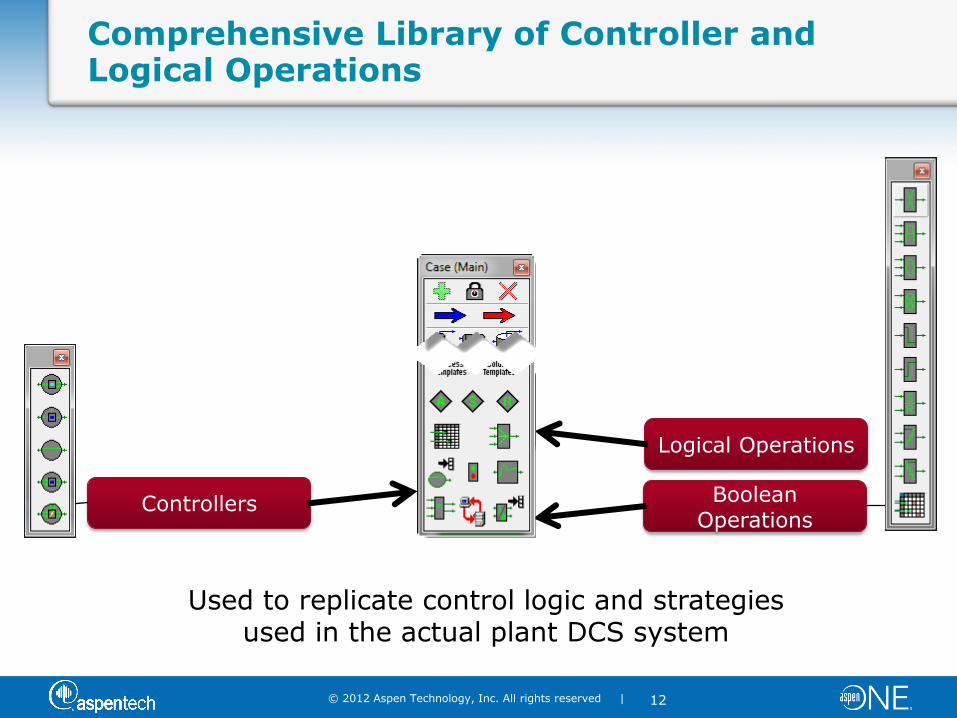
Controllers Boolean Operations
Logical Operations
Comprehensive Library of Controller and Logical Operations
Used to replicate control logic and strategies used in the actual plant DCS system

© 2012 Aspen Technology, Inc. All rights reserved |
13
Dynamics Assistant
Can be VERY useful as a guide to see what changes it recommends However, use the Make Changes button with caution as its advice may NOT be what you want to do
© 2012 Aspen Technology, Inc. All rights reserved |
14
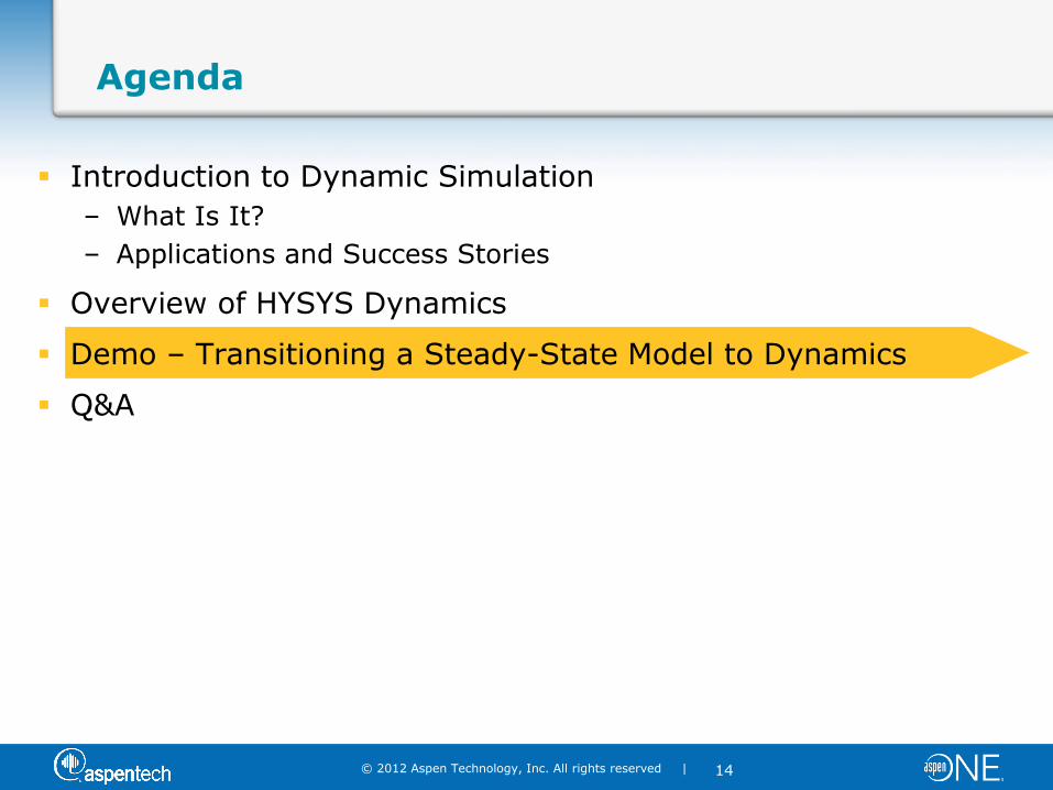
Agenda
Introduction to Dynamic Simulation
– What Is It?
– Applications and Success Stories
Overview of HYSYS Dynamics
Demo – Transitioning a Steady-State Model to Dynamics
Q&A
© 2012 Aspen Technology, Inc. All rights reserved |
15
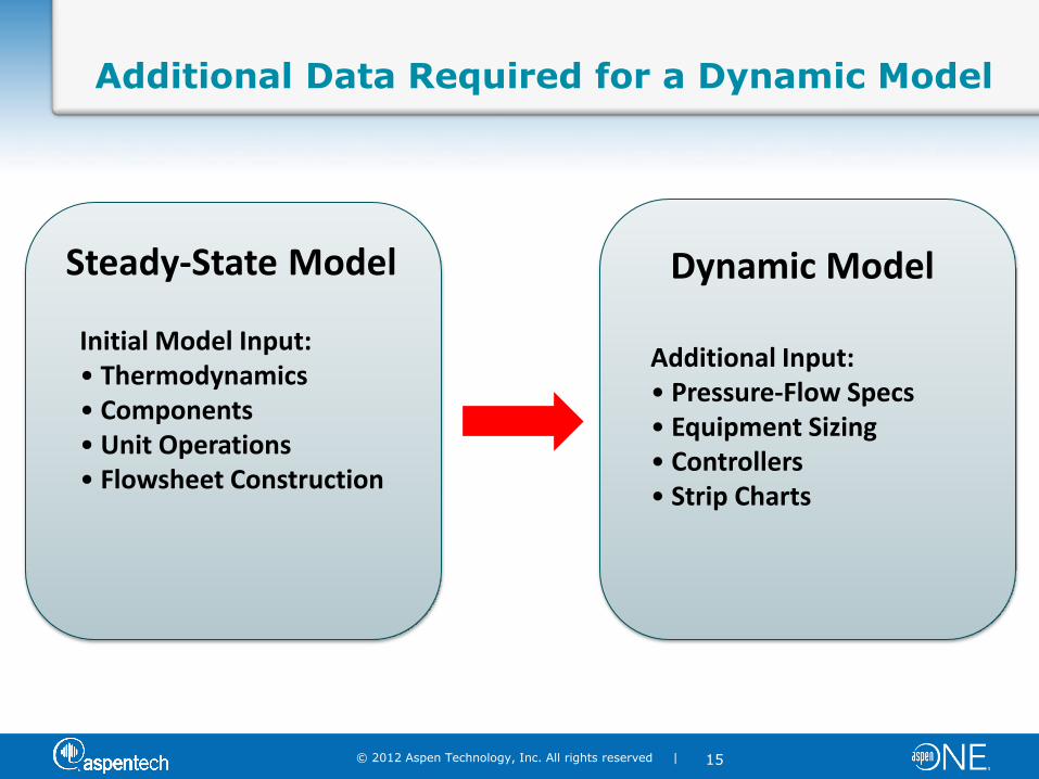
Additional Data Required for a Dynamic Model
Dynamic
Model
Steady-State Model
Initial Model Input: • Thermodynamics • Components • Unit Operations • Flowsheet Construction
Dynamic Model
Additional Input: • Pressure-Flow Specs • Equipment Sizing • Controllers • Strip Charts

© 2012 Aspen Technology, Inc. All rights reserved |
16
Transitioning from Steady State to Dynamics
4 Steps are Needed
1. Pressure Flow Setup and Specifications
2. Equipment Sizing
3. Set up your Control Strategy
4. Set up your Strip Charts and Run the Model

©2009 AspenTech. All Rights Reserved.
Transitioning from Steady State to Dynamics
Step 1: Pressure Flow Setup and Specifications

© 2012 Aspen Technology, Inc. All rights reserved |
18
Solver Basics
Aspen HYSYS Dynamics Solver is different from the Steady State Solver
Steady State – Pressures and Flows are not related, but can be set independently
Flow = 495 m3/s Pres = 130 kPa
Flow = 55 m3/s Pres = 120 kPa
Flow = 440 m3/s Pres = 120 kPa Flow = 440 m3/s
Pres = 375 kPa
Flow = 440 m3/s Pres = 365 kPa
Flow = 440 m3/s Pres = 375 kPa
No pressure drop across heat exchanger!
© 2012 Aspen Technology, Inc. All rights reserved |
19
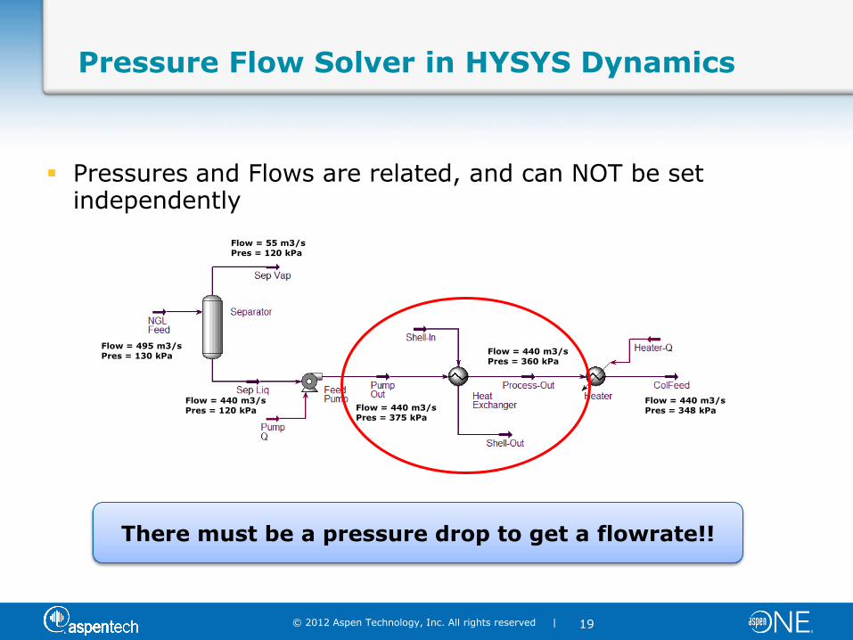
Pressure Flow Solver in HYSYS Dynamics
Pressures and Flows are related, and can NOT be set independently
Flow = 495 m3/s Pres = 130 kPa
Flow = 55 m3/s Pres = 120 kPa
Flow = 440 m3/s Pres = 120 kPa Flow = 440 m3/s
Pres = 375 kPa
Flow = 440 m3/s Pres = 348 kPa
Flow = 440 m3/s Pres = 360 kPa
There must be a pressure drop to get a flowrate!!
© 2012 Aspen Technology, Inc. All rights reserved |
20
Pressure-Flow Relationship Concepts
All unit operation models are categorized in one of the following categories
– Pressure Node Operations – contain significant volume and calculate a pressure based on the holdup of vapor in the unit operation
– Resistance Equation Operations – calculate a pressure drop based on a resistance equation
P/F specifications MUST be set on all boundary streams

© 2012 Aspen Technology, Inc. All rights reserved |
21
Guidelines for Transitioning to Dynamics
1. Add a resistance unit operation (e.g., valve, pump, compressor) between all pressure nodes in the flowsheet
– Internal flow rates will be calculated by the pressure gradients throughout the flowsheet
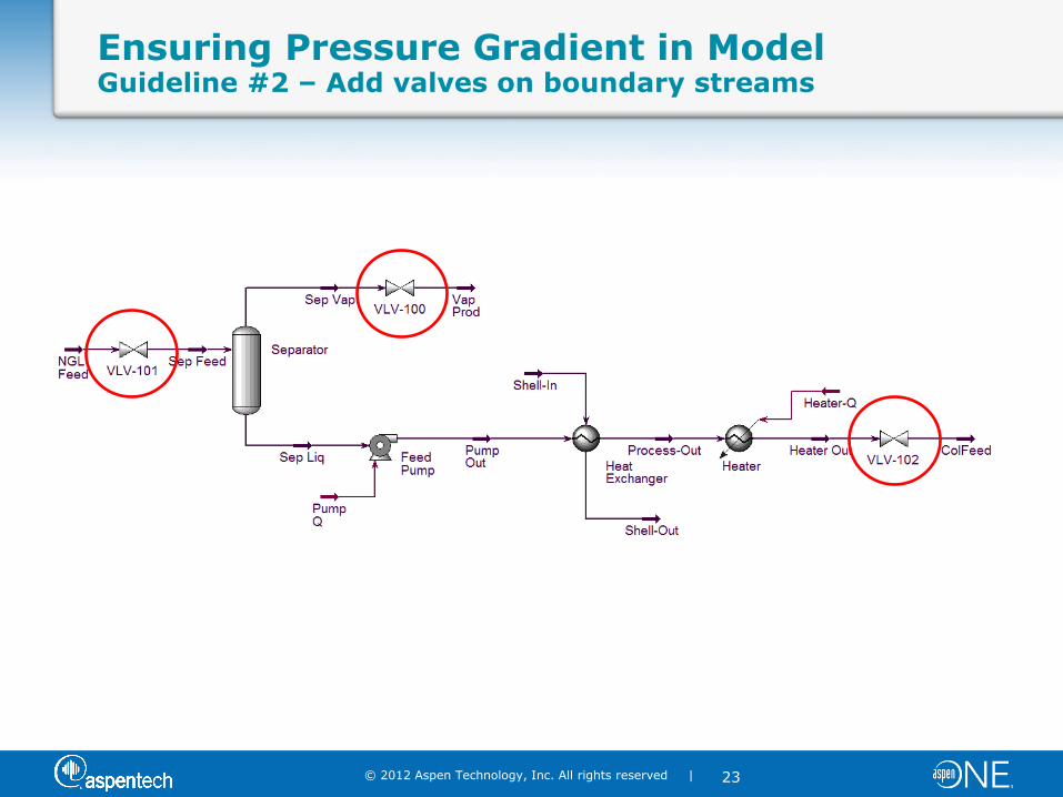
2. One P/F specification should be made on each boundary stream (feeds and products)
– Make pressure specifications on boundary streams attached to process equipment that use a resistance equation to calculate flow rates (e.g., valves, pumps, compressor, heat exchangers
– Recommendation – Add valves to all boundary streams (You will use them for flow controllers anyway once you add the control
strategy to the dynamic model!)

© 2012 Aspen Technology, Inc. All rights reserved |
22
Ensuring Pressure Gradient in Model Guideline #1 – Add valves between pressure nodes
Valve added between two vessels
© 2012 Aspen Technology, Inc. All rights reserved |
23
Ensuring Pressure Gradient in Model Guideline #2 – Add valves on boundary streams
© 2012 Aspen Technology, Inc. All rights reserved |
24
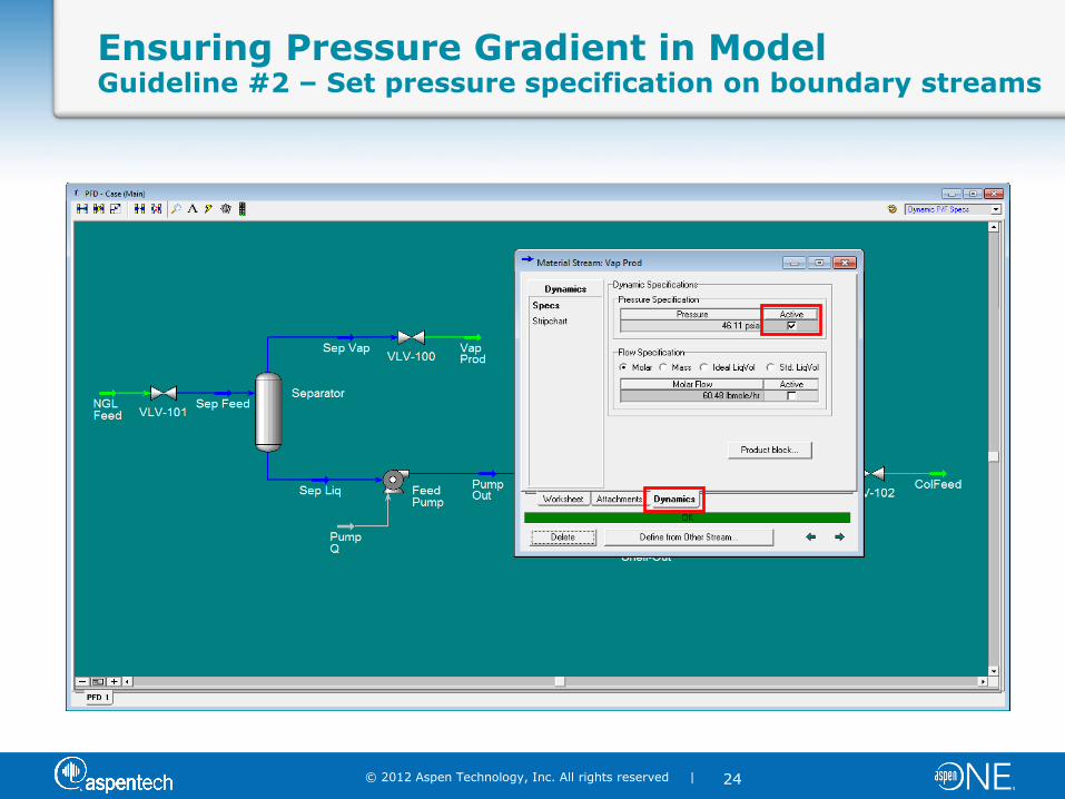
Ensuring Pressure Gradient in Model Guideline #2 – Set pressure specification on boundary streams
© 2012 Aspen Technology, Inc. All rights reserved |
25
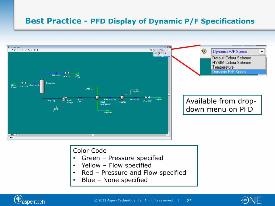
Best Practice - PFD Display of Dynamic P/F Specifications
Available from drop-down menu on PFD
Color Code • Green – Pressure specified • Yellow – Flow specified • Red – Pressure and Flow specified • Blue – None specified

©2009 AspenTech. All Rights Reserved.
Transitioning from Steady State to Dynamics
Step 2: Equipment Sizing

© 2012 Aspen Technology, Inc. All rights reserved |
27
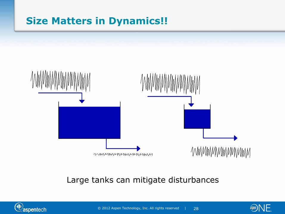
Size Matters in Dynamics!!
Consider the level control of a tank…..
“Noisy” feed flow
What impacts the stability of the outlet flow?
© 2012 Aspen Technology, Inc. All rights reserved |
28
Size Matters in Dynamics!!
Large tanks can mitigate disturbances
© 2012 Aspen Technology, Inc. All rights reserved |
29
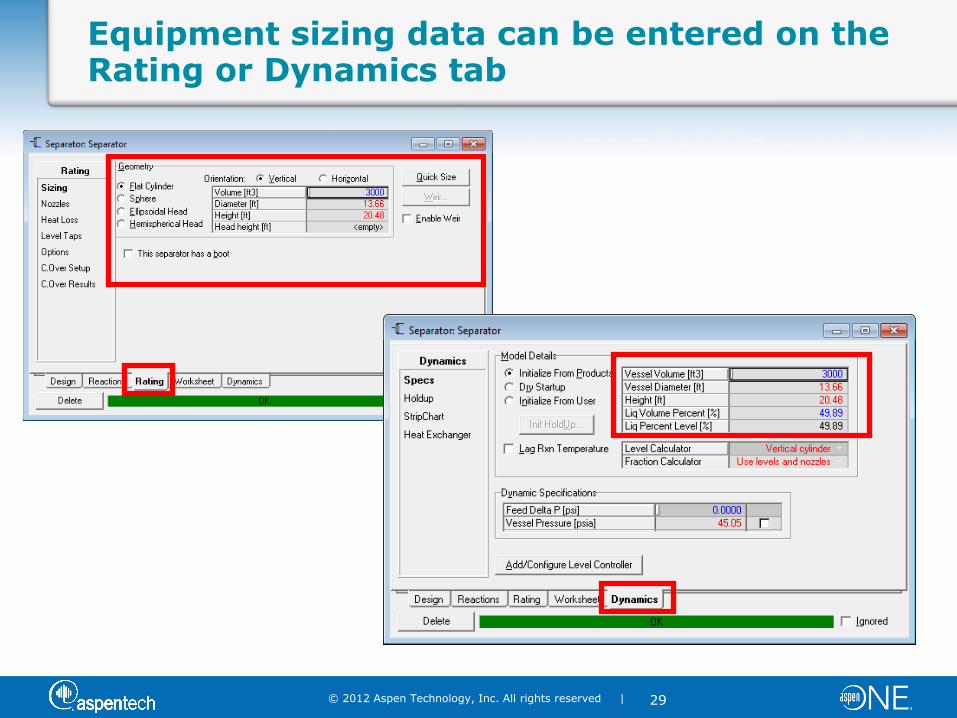
Equipment sizing data can be entered on the Rating or Dynamics tab

©2009 AspenTech. All Rights Reserved.
Transitioning from Steady State to Dynamics
Step 3: Setting Up Your Control Strategy
© 2012 Aspen Technology, Inc. All rights reserved |
31
Basics of Control Theory
A control system is designed to maintain stable process operations by compensating for disturbances
Key terms used by control engineers
– Process Variable (PV): Process variable that you want to maintain at a given operating point or set point
– Manipulated Variable (MV): Process variable that is changed by the controller
– Disturbance Variable (DV): A process variable which upsets a process and causes the control variables to move from the
desired set-points
Controls do what the process engineers can not

© 2012 Aspen Technology, Inc. All rights reserved |
32
Controller Library
PID Controller
© 2012 Aspen Technology, Inc. All rights reserved |
33
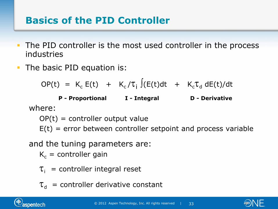
Basics of the PID Controller
The PID controller is the most used controller in the process industries
The basic PID equation is:
OP(t) = Kc E(t) + Kc /i (E(t)dt + Kcd dE(t)/dt
P - Proportional I - Integral D - Derivative
where:
OP(t) = controller output value
E(t) = error between controller setpoint and process variable
and the tuning parameters are:
Kc = controller gain
i = controller integral reset
d = controller derivative constant
© 2012 Aspen Technology, Inc. All rights reserved |
34
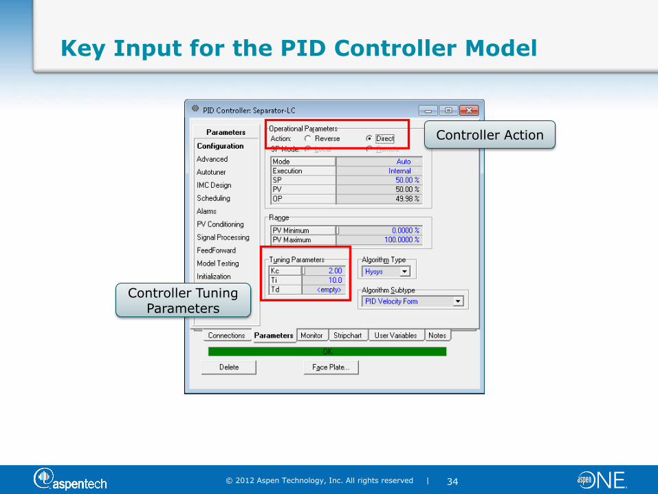
Key Input for the PID Controller Model
Controller Action
Controller Tuning Parameters
© 2012 Aspen Technology, Inc. All rights reserved |
35
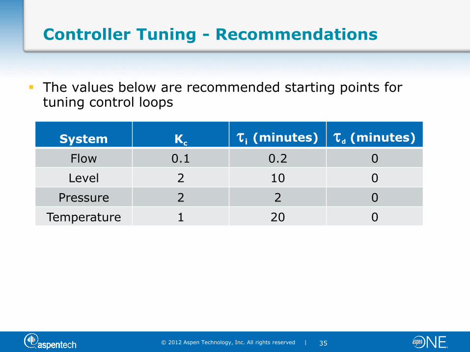
Controller Tuning - Recommendations
The values below are recommended starting points for tuning control loops
System Kc
i (minutes) d (minutes)
Flow 0.1 0.2 0
Level 2 10 0
Pressure 2 2 0
Temperature 1 20 0
©2009 AspenTech. All Rights Reserved.
Transitioning from Steady State to Dynamics
Step 4: Running Your Model
© 2012 Aspen Technology, Inc. All rights reserved |
37
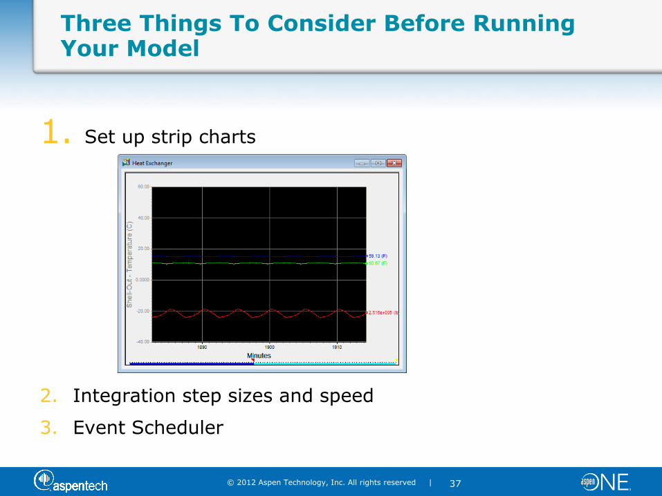
Three Things To Consider Before Running Your Model
1. Set up strip charts
2. Integration step sizes and speed
3. Event Scheduler
© 2012 Aspen Technology, Inc. All rights reserved |
38
Transitioning from Steady State to Dynamics
4 Steps are Needed
1. Pressure Flow Setup and Specifications
2. Equipment Sizing
3. Set up your Control Strategy
4. Set up your Strip Charts and Run the Model
© 2012 Aspen Technology, Inc. All rights reserved |
39
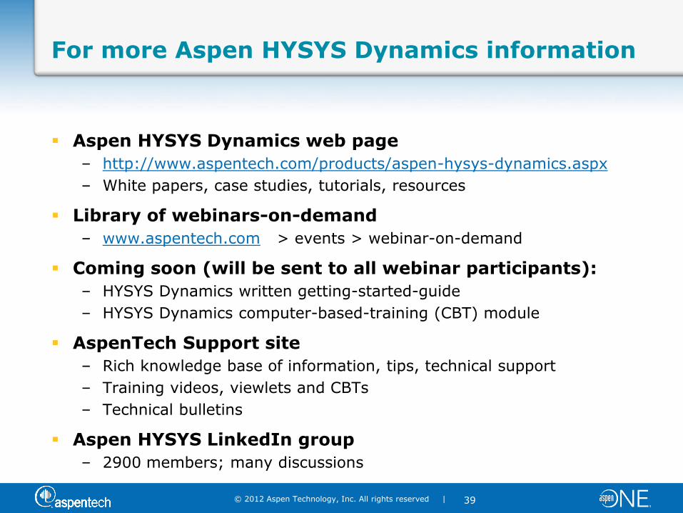
For more Aspen HYSYS Dynamics information
Aspen HYSYS Dynamics web page
– http://www.aspentech.com/products/aspen-hysys-dynamics.aspx
– White papers, case studies, tutorials, resources
Library of webinars-on-demand
– www.aspentech.com > events > webinar-on-demand
Coming soon (will be sent to all webinar participants):
– HYSYS Dynamics written getting-started-guide
– HYSYS Dynamics computer-based-training (CBT) module
AspenTech Support site
– Rich knowledge base of information, tips, technical support
– Training videos, viewlets and CBTs
– Technical bulletins
Aspen HYSYS LinkedIn group
– 2900 members; many discussions

© 2012 Aspen Technology, Inc. All rights reserved |
40
OPTIMIZE™ 2013 Global Conference
Join us in Boston for the industry’s must-attend event!
OPTIMIZE 2013 6 – 8 May 2013 The Westin Waterfront Hotel Boston, MA USA For more information, visit www.aspentech.com/agc

© 2012 Aspen Technology, Inc. All rights reserved |
41
Questions?
© 2012 Aspen Technology, Inc. All rights reserved |
42
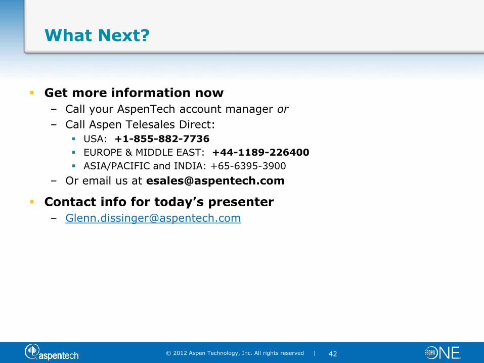
What Next?
Get more information now
– Call your AspenTech account manager or
– Call Aspen Telesales Direct:
USA: +1-855-882-7736
EUROPE & MIDDLE EAST: +44-1189-226400
ASIA/PACIFIC and INDIA: +65-6395-3900
– Or email us at [email protected]
Contact info for today’s presenter