Embed Size (px)
Citation preview

Version 11.1
Part Number: Aspen Plus® 11.1September 2001Copyright (c) 1981-2001 by Aspen Technology, Inc. All rights reserved.
Aspen Plus®, Aspen Properties®, Aspen Engineering Suite™, AspenTech®, ModelManager™, the aspen leaf logoand Plantelligence are trademarks or registered trademarks of Aspen Technology, Inc., Cambridge, MA.
BATCHFRAC™ and RATEFRAC™ are trademarks of Koch Engineering Company, Inc.
All other brand and product names are trademarks or registered trademarks of their respective companies.
This manual is intended as a guide to using AspenTech's software. This documentation contains AspenTechproprietary and confidential information and may not be disclosed, used, or copied without the prior consent ofAspenTech or as set forth in the applicable license agreement. Users are solely responsible for the proper use of thesoftware and the application of the results obtained.
Although AspenTech has tested the software and reviewed the documentation, the sole warranty for the software maybe found in the applicable license agreement between AspenTech and the user. ASPENTECH MAKES NOWARRANTY OR REPRESENTATION, EITHER EXPRESSED OR IMPLIED, WITH RESPECT TO THISDOCUMENTATION, ITS QUALITY, PERFORMANCE, MERCHANTABILITY, OR FITNESS FOR APARTICULAR PURPOSE.
CorporateAspen Technology, Inc.Ten Canal ParkCambridge, MA 02141-2201USAPhone: (1) (617) 949-1021Toll Free: (1) (888) 996-7001Fax: (1) (617) 949-1724URL: http://www.aspentech.com
DivisionDesign, Simulation and Optimization SystemsAspen Technology, Inc.Ten Canal ParkCambridge, MA 02141-2201USAPhone: (617) 949-1000Fax:(617) 949-1030
Getting Started - Electrolytes Contents •••• iii
Contents
Introduction 1-1Why Use Electrolyte Simulation? ....................................................................................1-2What is an Aspen Plus Electrolyte Model? ......................................................................1-2Sessions in this Book .......................................................................................................1-3Using Backup Files ..........................................................................................................1-4Related Documentation ....................................................................................................1-4
Getting Started Guides .........................................................................................1-4Installation Guide .................................................................................................1-4User Guide............................................................................................................1-4
Technical Support ............................................................................................................1-5Online Technical Support Center .........................................................................1-5Contacting Customer Support ..............................................................................1-5Hours ....................................................................................................................1-5Phone....................................................................................................................1-6Fax........................................................................................................................1-7E-mail ...................................................................................................................1-7
Modeling Electrolyte Chemistry 2-1Electrolyte Chemistry Flowsheet .....................................................................................2-2Starting Aspen Plus ..........................................................................................................2-2
To Start Aspen Plus..............................................................................................2-2To Select the Template Option.............................................................................2-2To Specify the Application Type and Run Type for the New Run ......................2-2
Drawing the Graphical Simulation Flowsheet .................................................................2-4Specifying Title, Stream Properties, and Global Options.................................................2-5
To Specify Flows on a Mole Basis for this Simulation ........................................2-6Reviewing Report Options ...................................................................................2-6
Specifying Components ...................................................................................................2-6To Rename H2O to Water....................................................................................2-7
The Electrolyte Wizard.....................................................................................................2-7To Remove Salts from the Solution Chemistry ...................................................2-9
Examining Generated Chemistry ...................................................................................2-11To Examine the Generated Chemistry................................................................2-11To View a Particular Reaction ...........................................................................2-12To View the Equilibrium Constants for the Salt Reactions................................2-13
Selecting Electrolyte Property Models ...........................................................................2-14
iv •••• Contents Getting Started - Electrolytes
Entering Stream Data .....................................................................................................2-16Specifying the Flash Block.............................................................................................2-17Specifying Additional Stream Properties .......................................................................2-17
To Specify Additional Properties........................................................................2-18Running the Simulation..................................................................................................2-19Examining Simulation Results.......................................................................................2-19Exiting Aspen Plus .........................................................................................................2-21
Modeling a Sour Water Stripper 3-1Sour Water Stripper Flowsheet ........................................................................................3-2Starting Aspen Plus ..........................................................................................................3-3
To Start Aspen Plus..............................................................................................3-3To Select the Template Option.............................................................................3-3To Specify the Application Type and Run Type for the New Run ......................3-3
Drawing the Graphical Simulation Flowsheet .................................................................3-4Specifying Title, Stream Properties, and Global Options ................................................3-5
To Review the Report Options Specified in the Selected Template.....................3-6To Move to the Next Required Input Sheet .........................................................3-6
Specifying Components ...................................................................................................3-7The Electrolyte Wizard ....................................................................................................3-7
To Remove Ammonium Carbamate Formation from the Solution Chemistry....3-8To Remove the Salts from the Solution Chemistry..............................................3-8
Examining Generated Chemistry ...................................................................................3-11To Examine the Generated Chemistry ...............................................................3-11To View the Generated Chemistry.....................................................................3-11
Entering Stream Data .....................................................................................................3-14Specifying the RadFrac Block........................................................................................3-15
To Review the Types of Specifications that You Can Make for RadFrac .........3-15To Specify that this Column Operates Isobarically at 15 psia ...........................3-17To Define the First Design Specification ...........................................................3-17To Define Another Design Specification ...........................................................3-18To Define the First Manipulated Variable .........................................................3-18To Define the Second Manipulated Variable .....................................................3-19To Change the Report ........................................................................................3-20
Running the Simulation..................................................................................................3-21Examining Simulation Results.......................................................................................3-22
To View RadFrac Results ..................................................................................3-22To View Design Spec Results ............................................................................3-23To View Vary Results ........................................................................................3-23To View Composition Profiles...........................................................................3-23To View these Results........................................................................................3-24
Converting to True Components ....................................................................................3-26To Tell Aspen Plus to Use the True Component Approach...............................3-26To Revise the RadFrac Design Specification to Apply to the ApparentComposition of NH3 ..........................................................................................3-26
Getting Started - Electrolytes Contents •••• v
Running the True Component Simulation .....................................................................3-28To View Selected Results of the True Component Simulation .........................3-28
Exiting Aspen Plus .........................................................................................................3-29
Connecting to the Aspen Plus Simulation Engine 4-1

vi •••• Contents Getting Started - Electrolytes
Getting Started - Electrolytes Introduction •••• 1-1
Introduction
You can easily model all types of electrolyte systems with AspenPlus, including systems with strong electrolytes, weak electrolytes,salt precipitation, even mixed solvents.
The two sessions in this book - Modeling Electrolyte Chemistryand Modeling a Sour Water Stripper- introduce you to simulatingelectrolyte systems with Aspen Plus by guiding you through twosimulations.
Getting Started Modeling Processes with Electrolytes assumes thatyou have an installed copy of the Aspen Plus software.
1-2 •••• Introduction Getting Started - Electrolytes
Why Use Electrolyte Simulation?A rigorous treatment of electrolytes is needed to model manyindustrial systems. With the Aspen Plus electrolyte capabilities,you can model:
Sour water solutions. Water containing dissolved H2S, NH3, CO2,HCN, sometimes with additional solvents
Aqueous amines for gas sweetening. Water containing DGA,MEA, DEA, or MDEA for the removal of H2S and CO2
Aqueous acids or bases. HCl, HBr, H2SO4, H3PO4, HNO3, HF,NaOH, KOH, and others, in aqueous solution, sometimes withadditional solvents
Salt solutions. NaCl, KCl, Na2SO4, CaSO4, CaCO3 in solution,sometimes with participation
What is an Aspen Plus ElectrolyteModel?In Aspen Plus, an electrolyte system is defined as one in whichsome of the molecular species dissociate partially or completelyinto ions in a liquid solvent, and/or some of the molecular speciesprecipitate as salts. These dissociation and precipitation reactionsoccur fast enough that the reactions can be considered to be atchemical equilibrium. The liquid phase equilibrium reactions thatdescribe this behavior are referred to as the solution chemistry. InAspen Plus, solution chemistry is often referred to simply asChemistry.
Solution chemistry has a major impact on the simulation ofelectrolyte systems. For nonelectrolyte systems, chemical reactionsgenerally occur only in reactors. In Aspen Plus, all unit operationmodels can handle electrolyte reactions.
Solution chemistry also impacts physical property calculations andphase equilibrium calculations. The presence of ions in the liquidphase causes highly nonideal thermodynamic behavior. Aspen Plusprovides specialized thermodynamic models and built-in data torepresent the nonideal behavior of liquid phase components inorder to get accurate results.
Getting Started - Electrolytes Introduction •••• 1-3
Sessions in this BookThe two sessions in the book illustrate the following concepts:• Types of electrolyte components
− Solvents− Solutes− Ions− Salts
• Types of reactions in electrolyte solution chemistry− Complete dissociation− Partial dissociation (equilibrium reaction)− Salt precipitation (equilibrium reaction)
• Automatic Chemistry generation• Recommended physical property methods for electrolytes• Methods for calculating and reporting electrolyte systems
− True component approach− Apparent component approach
• Use of stream properties (Property Sets) for electrolytes
Follow the steps inChapter
To learn how to
2 Modeling ElectrolyteChemistry
Define electrolyte components.Use automatic chemistry generation.Examine Chemistry data.View electrolyte databank parameters.Use the true component modelingapproach.
3 Modeling a Sour WaterStripper
Modify the generated Chemistry.Use the apparent component approach forelectrolytes.Convert from apparent componentapproach to true component approach.

1-4 •••• Introduction Getting Started - Electrolytes
Using Backup FilesWe recommend that you perform all sessions sequentially, becauseChapter 3 assumes you are familiar with the concepts presented inChapter 2.
Aspen Plus provides backup files containing all problemspecifications and results for each tutorial session. You can use thebackup files to check your results.
Related DocumentationIn addition to this document, a number of other documents areprovided to help users learn and use Aspen Plus. Thedocumentation set consists of the following:
Aspen Plus Getting Started Building and Running a Process Model
Aspen Plus Getting Started Modeling Processes with Solids
Aspen Plus Getting Started Modeling Petroleum Processes
Aspen Plus Getting Started Using Equation-Oriented Modeling
Aspen Plus Getting Started Customizing Unit Operation Models
AES Installation Manual
Aspen Plus User Guide
Getting StartedGuides
Installation Guide
User Guide
Getting Started - Electrolytes Introduction •••• 1-5
Technical SupportAspenTech customers with a valid license and softwaremaintenance agreement can register to access the Online TechnicalSupport Center at:
http://support.aspentech.comThis web support site allows you to:• Access current product documentation• Search for tech tips, solutions and frequently asked questions
(FAQs)• Search for and download application examples• Search for and download service packs and product updates• Submit and track technical issues• Search for and review known limitations• Send suggestions
Registered users can also subscribe to our Technical Supporte-Bulletins. These e-Bulletins are used to proactively alert users toimportant technical support information such as:• Technical advisories• Product updates• Service Pack announcements• Product release announcements
Customer support is also available by phone, fax, and email forcustomers with a current support contract for this product. For themost up-to-date phone listings, please see the Online TechnicalSupport Center at http://support.aspentech.com.
Support Centers Operating Hours
North America 8:00 – 20:00 Eastern TimeSouth America 9:00 – 17:00 Local timeEurope 8:30 – 18:00 Central European timeAsia and Pacific Region 9:00 – 17:30 Local time
Online TechnicalSupport Center
Contacting CustomerSupport
Hours

1-6 •••• Introduction Getting Started - Electrolytes
SupportCenters
Phone Numbers
1-888-996-7100 Toll-free from U.S., Canada, Mexico1-281-584-4357 North America Support Center
NorthAmerica
(52) (5) 536-2809 Mexico Support Center(54) (11) 4361-7220 Argentina Support Center(55) (11) 5012-0321 Brazil Support Center(0800) 333-0125 Toll-free to U.S. from Argentina(000) (814) 550-4084 Toll-free to U.S. from Brazil
SouthAmerica
8001-2410 Toll-free to U.S. from Venezuela(32) (2) 701-95-55 European Support CenterCountry specific toll-free numbers:Belgium (0800) 40-687Denmark 8088-3652Finland (0) (800) 1-19127France (0805) 11-0054Ireland (1) (800) 930-024Netherlands (0800) 023-2511Norway (800) 13817Spain (900) 951846Sweden (0200) 895-284Switzerland (0800) 111-470
Europe
UK (0800) 376-7903(65) 395-39-00 SingaporeAsia and
PacificRegion
(81) (3) 3262-1743 Tokyo
Phone
Getting Started - Electrolytes Introduction •••• 1-7
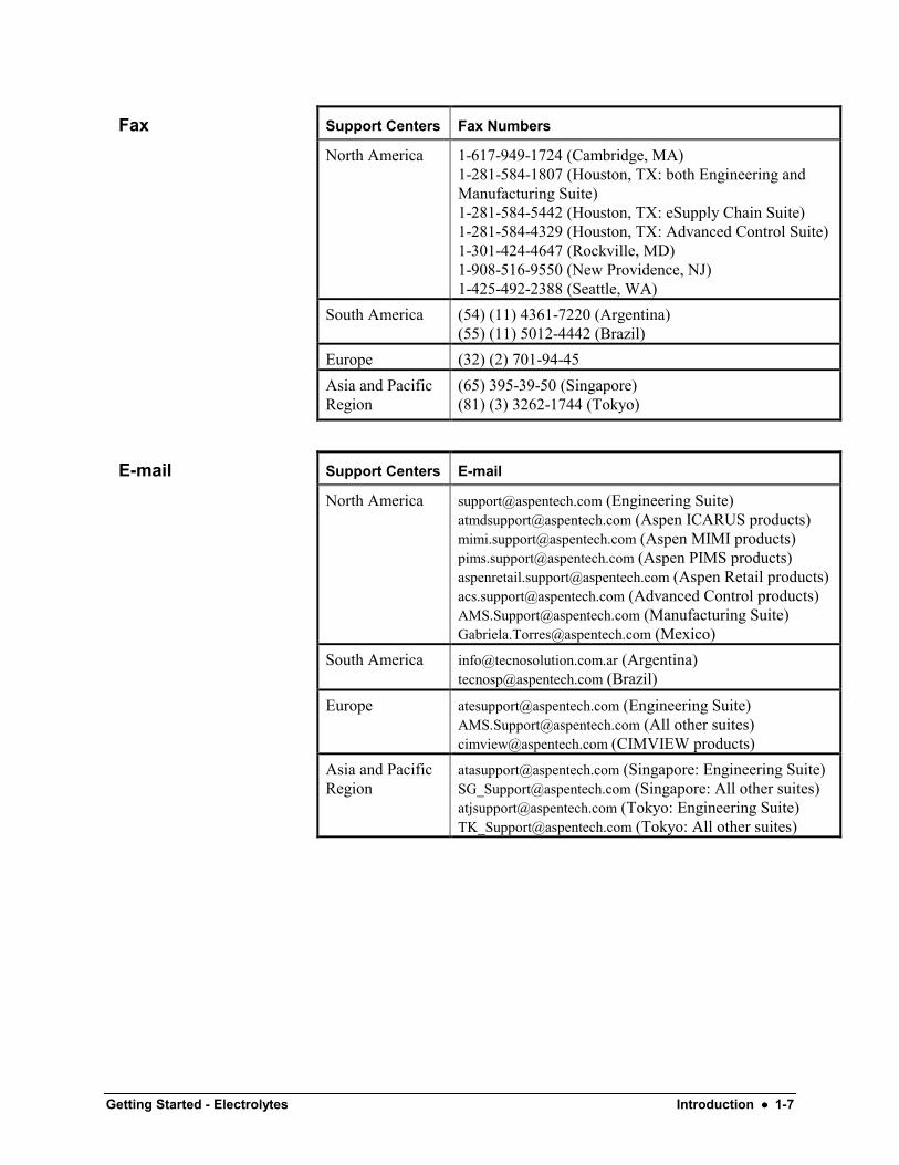
Support Centers Fax Numbers
North America 1-617-949-1724 (Cambridge, MA)1-281-584-1807 (Houston, TX: both Engineering andManufacturing Suite)1-281-584-5442 (Houston, TX: eSupply Chain Suite)1-281-584-4329 (Houston, TX: Advanced Control Suite)1-301-424-4647 (Rockville, MD)1-908-516-9550 (New Providence, NJ)1-425-492-2388 (Seattle, WA)
South America (54) (11) 4361-7220 (Argentina)(55) (11) 5012-4442 (Brazil)
Europe (32) (2) 701-94-45Asia and PacificRegion
(65) 395-39-50 (Singapore)(81) (3) 3262-1744 (Tokyo)
Support Centers E-mail
North America [email protected] (Engineering Suite)[email protected] (Aspen ICARUS products)[email protected] (Aspen MIMI products)[email protected] (Aspen PIMS products)[email protected] (Aspen Retail products)[email protected] (Advanced Control products)[email protected] (Manufacturing Suite)[email protected] (Mexico)
South America [email protected] (Argentina)[email protected] (Brazil)
Europe [email protected] (Engineering Suite)[email protected] (All other suites)[email protected] (CIMVIEW products)
Asia and PacificRegion
[email protected] (Singapore: Engineering Suite)[email protected] (Singapore: All other suites)[email protected] (Tokyo: Engineering Suite)[email protected] (Tokyo: All other suites)
Fax

1-8 •••• Introduction Getting Started - Electrolytes
Getting Started - Electrolytes Modeling Electrolyte Chemistry •••• 2-1
Modeling Electrolyte Chemistry
In this simulation mix and flash two feed streams containingaqueous electrolytes.
You will:• Define electrolyte components• Use the Electrolytes Expert System• Examine Chemistry data• View electrolytes databank parameters• Use the true components modeling approach• Allow about 45 minutes to do this simulation.
2-2 •••• Modeling Electrolyte Chemistry Getting Started - Electrolytes
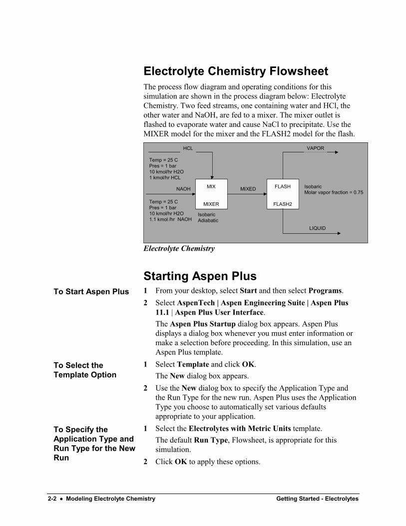
Electrolyte Chemistry FlowsheetThe process flow diagram and operating conditions for thissimulation are shown in the process diagram below: ElectrolyteChemistry. Two feed streams, one containing water and HCl, theother water and NaOH, are fed to a mixer. The mixer outlet isflashed to evaporate water and cause NaCl to precipitate. Use theMIXER model for the mixer and the FLASH2 model for the flash.
MIX
MIXER
FLASH
FLASH2
HCL
NAOH
LIQUID
VAPOR
MIXED
IsobaricAdiabatic
IsobaricMolar vapor fraction = 0.75
Temp = 25 CPres = 1 bar10 kmol/hr H2O1 kmol/hr HCL
Temp = 25 CPres = 1 bar10 kmol/hr H2O1.1 kmol /hr NAOH
Electrolyte Chemistry
Starting Aspen Plus1 From your desktop, select Start and then select Programs.2 Select AspenTech | Aspen Engineering Suite | Aspen Plus
11.1 | Aspen Plus User Interface.The Aspen Plus Startup dialog box appears. Aspen Plusdisplays a dialog box whenever you must enter information ormake a selection before proceeding. In this simulation, use anAspen Plus template.
1 Select Template and click OK.The New dialog box appears.
2 Use the New dialog box to specify the Application Type andthe Run Type for the new run. Aspen Plus uses the ApplicationType you choose to automatically set various defaultsappropriate to your application.
1 Select the Electrolytes with Metric Units template.The default Run Type, Flowsheet, is appropriate for thissimulation.
2 Click OK to apply these options.
To Start Aspen Plus
To Select theTemplate Option
To Specify theApplication Type andRun Type for the NewRun
Getting Started - Electrolytes Modeling Electrolyte Chemistry •••• 2-3
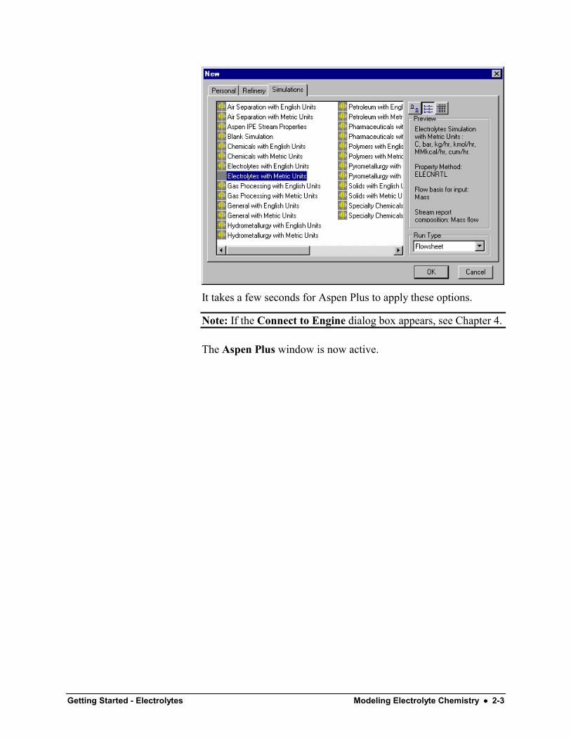
It takes a few seconds for Aspen Plus to apply these options.
Note: If the Connect to Engine dialog box appears, see Chapter 4.
The Aspen Plus window is now active.
2-4 •••• Modeling Electrolyte Chemistry Getting Started - Electrolytes
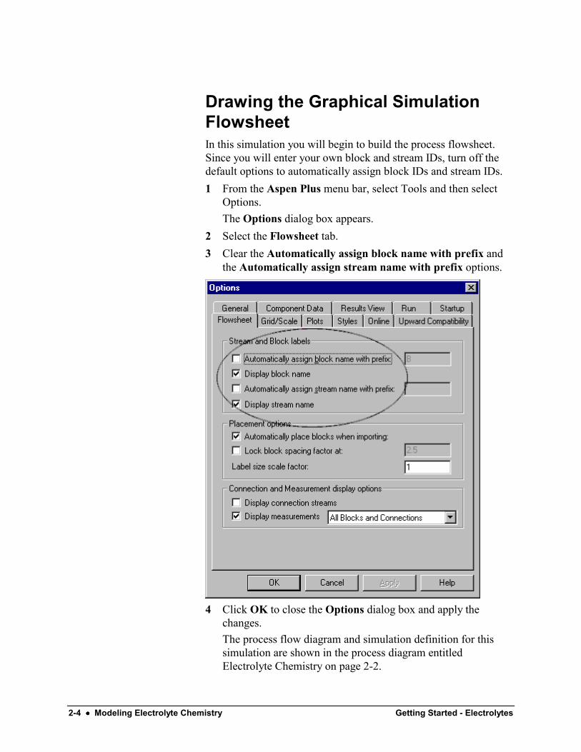
Drawing the Graphical SimulationFlowsheetIn this simulation you will begin to build the process flowsheet.Since you will enter your own block and stream IDs, turn off thedefault options to automatically assign block IDs and stream IDs.1 From the Aspen Plus menu bar, select Tools and then select
Options.The Options dialog box appears.
2 Select the Flowsheet tab.3 Clear the Automatically assign block name with prefix and
the Automatically assign stream name with prefix options.
4 Click OK to close the Options dialog box and apply thechanges.The process flow diagram and simulation definition for thissimulation are shown in the process diagram entitledElectrolyte Chemistry on page 2-2.
Getting Started - Electrolytes Modeling Electrolyte Chemistry •••• 2-5
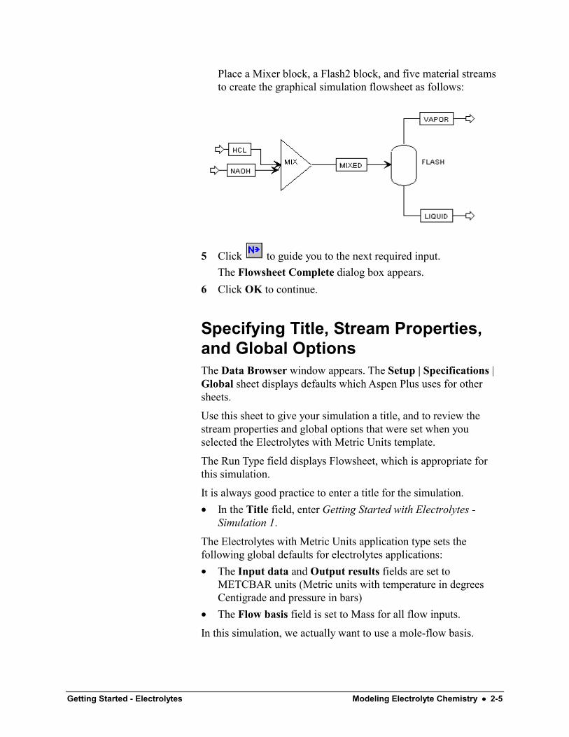
Place a Mixer block, a Flash2 block, and five material streamsto create the graphical simulation flowsheet as follows:
5 Click to guide you to the next required input.The Flowsheet Complete dialog box appears.
6 Click OK to continue.
Specifying Title, Stream Properties,and Global OptionsThe Data Browser window appears. The Setup | Specifications |Global sheet displays defaults which Aspen Plus uses for othersheets.
Use this sheet to give your simulation a title, and to review thestream properties and global options that were set when youselected the Electrolytes with Metric Units template.
The Run Type field displays Flowsheet, which is appropriate forthis simulation.
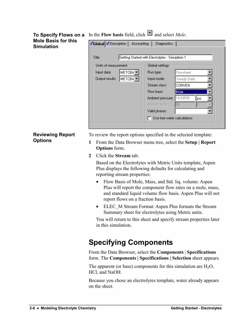
It is always good practice to enter a title for the simulation.• In the Title field, enter Getting Started with Electrolytes -
Simulation 1.
The Electrolytes with Metric Units application type sets thefollowing global defaults for electrolytes applications:• The Input data and Output results fields are set to
METCBAR units (Metric units with temperature in degreesCentigrade and pressure in bars)
• The Flow basis field is set to Mass for all flow inputs.
In this simulation, we actually want to use a mole-flow basis.
2-6 •••• Modeling Electrolyte Chemistry Getting Started - Electrolytes
In the Flow basis field, click and select Mole.
To review the report options specified in the selected template:1 From the Data Browser menu tree, select the Setup | Report
Options form.2 Click the Stream tab.
Based on the Electrolytes with Metric Units template, AspenPlus displays the following defaults for calculating andreporting stream properties:• Flow Basis of Mole, Mass, and Std. liq. volume: Aspen
Plus will report the component flow rates on a mole, mass,and standard liquid volume flow basis. Aspen Plus will notreport flows on a fraction basis.
• ELEC_M Stream Format: Aspen Plus formats the StreamSummary sheet for electrolytes using Metric units.
You will return to this sheet and specify stream properties laterin this simulation.
Specifying ComponentsFrom the Data Browser, select the Components | Specificationsform. The Components | Specifications | Selection sheet appears.
The apparent (or base) components for this simulation are H2O,HCl, and NaOH.
Because you chose an electrolytes template, water already appearson the sheet.
To Specify Flows on aMole Basis for thisSimulation
Reviewing ReportOptions
Getting Started - Electrolytes Modeling Electrolyte Chemistry •••• 2-7
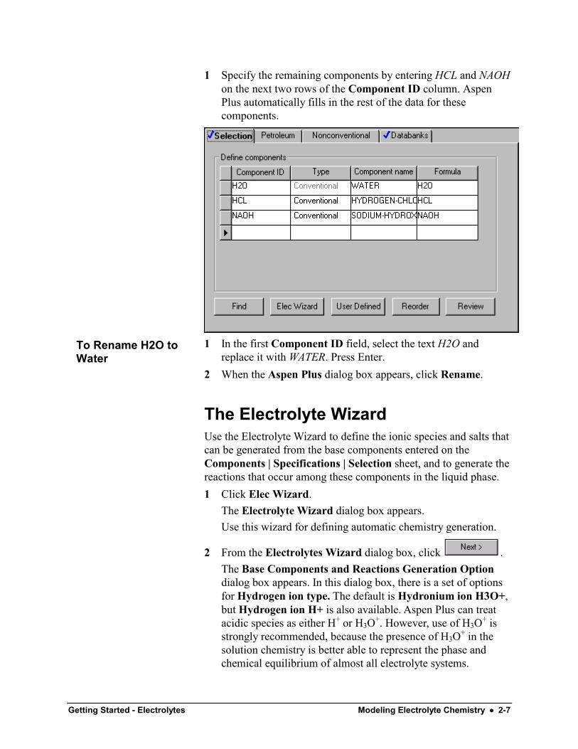
1 Specify the remaining components by entering HCL and NAOHon the next two rows of the Component ID column. AspenPlus automatically fills in the rest of the data for thesecomponents.
1 In the first Component ID field, select the text H2O andreplace it with WATER. Press Enter.
2 When the Aspen Plus dialog box appears, click Rename.
The Electrolyte WizardUse the Electrolyte Wizard to define the ionic species and salts thatcan be generated from the base components entered on theComponents | Specifications | Selection sheet, and to generate thereactions that occur among these components in the liquid phase.1 Click Elec Wizard.
The Electrolyte Wizard dialog box appears.Use this wizard for defining automatic chemistry generation.
2 From the Electrolytes Wizard dialog box, click .The Base Components and Reactions Generation Optiondialog box appears. In this dialog box, there is a set of optionsfor Hydrogen ion type. The default is Hydronium ion H3O+,but Hydrogen ion H+ is also available. Aspen Plus can treatacidic species as either H+ or H3O+. However, use of H3O+ isstrongly recommended, because the presence of H3O+ in thesolution chemistry is better able to represent the phase andchemical equilibrium of almost all electrolyte systems.
To Rename H2O toWater
2-8 •••• Modeling Electrolyte Chemistry Getting Started - Electrolytes
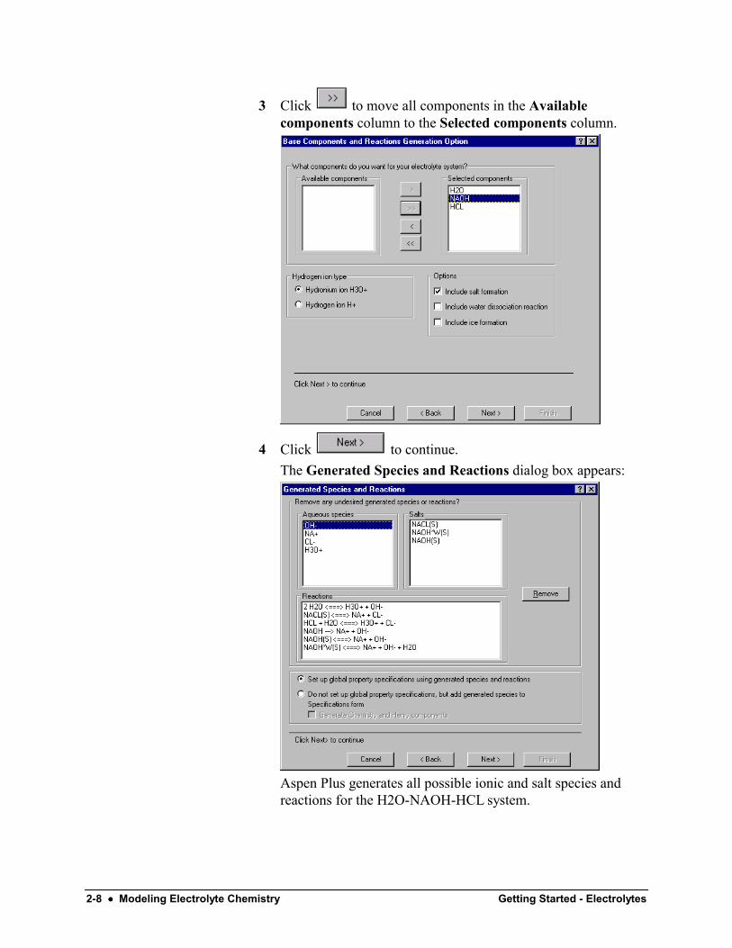
3 Click to move all components in the Availablecomponents column to the Selected components column.
4 Click to continue.The Generated Species and Reactions dialog box appears:
Aspen Plus generates all possible ionic and salt species andreactions for the H2O-NAOH-HCL system.
Getting Started - Electrolytes Modeling Electrolyte Chemistry •••• 2-9
In the Reactions section in the Generated Species and Reactionsdialog box, different style arrows denote the following reactiontypes:
<===> Denotes ionic equilibrium or salt precipitation---> Denotes complete dissociation
In this example, three types of reactions are generated: ionicequilibrium, complete dissociation, and salt precipitation.
The dissociation of water and the dissociation of HCl areequilibrium reactions. NaCl precipitation/dissolution is also anequilibrium reaction. In contrast, NAOH dissociates completelyand irreversibly into Na+ and OH–.
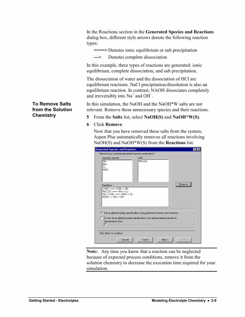
In this simulation, the NaOH and the NaOH*W salts are notrelevant. Remove these unnecessary species and their reactions.5 From the Salts list, select NaOH(S) and NaOH*W(S).6 Click Remove.
Now that you have removed these salts from the system,Aspen Plus automatically removes all reactions involvingNaOH(S) and NaOH*W(S) from the Reactions list.
Note: Any time you know that a reaction can be neglectedbecause of expected process conditions, remove it from thesolution chemistry to decrease the execution time required for yoursimulation.
To Remove Saltsfrom the SolutionChemistry
2-10 •••• Modeling Electrolyte Chemistry Getting Started - Electrolytes
7 On the Generated Species and Reactions dialog box click
to accept the remaining generated species andreactions.The Simulation Approach dialog box appears, allowing you tochoose between the true component approach and the apparentcomponent approach.
8 Select the True component approach option.When you use the true component approach, Aspen Plus solvesthe equations describing solution chemistry simultaneouslywith the unit operation equations. The unit operations dealdirectly with the ions and salts formed by solution chemistry. Inaddition, the true component approach defines how Aspen Plusreports the simulation results. Results are reported in terms ofthe ions, salts, and molecular components that are actuallypresent, not in terms of the original base components.For example, the generated chemistry for this system specifiesthat NaOH fully dissociates into NA+ and OH–. If you choosethe true component approach, Aspen Plus will report NaOHflow in terms of NA+ flow and OH– flow, not in terms of theNaOH base component flow. You can request that compositionand flows also be reported in terms of the apparent (base)components. You will do this later in this simulation.
9 Click to move to the next dialog box.The Summary dialog box appears, providing Aspen Pluselectrolytes expert system information.
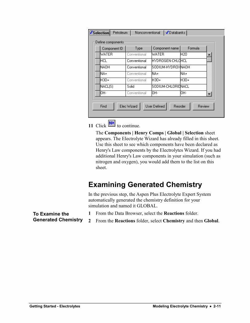
10 Click Finish to close the dialog box.On the Components | Specifications | Selection sheet,Aspen Plus has now added the generated electrolytecomponents. Since all components are databank components,Aspen Plus automatically retrieves all relevant physicalproperty parameters. Note that the salt NACL(S) is identifiedas type Solid.
Getting Started - Electrolytes Modeling Electrolyte Chemistry •••• 2-11
11 Click to continue.The Components | Henry Comps | Global | Selection sheetappears. The Electrolyte Wizard has already filled in this sheet.Use this sheet to see which components have been declared asHenry's Law components by the Electrolytes Wizard. If you hadadditional Henry's Law components in your simulation (such asnitrogen and oxygen), you would add them to the list on thissheet.
Examining Generated ChemistryIn the previous step, the Aspen Plus Electrolyte Expert Systemautomatically generated the chemistry definition for yoursimulation and named it GLOBAL.1 From the Data Browser, select the Reactions folder.2 From the Reactions folder, select Chemistry and then Global.
To Examine theGenerated Chemistry
2-12 •••• Modeling Electrolyte Chemistry Getting Started - Electrolytes
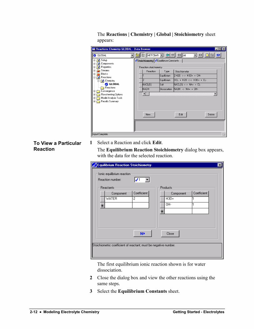
The Reactions | Chemistry | Global | Stoichiometry sheetappears:
1 Select a Reaction and click Edit.The Equilibrium Reaction Stoichiometry dialog box appears,with the data for the selected reaction.
The first equilibrium ionic reaction shown is for waterdissociation.
2 Close the dialog box and view the other reactions using thesame steps.
3 Select the Equilibrium Constants sheet.
To View a ParticularReaction

Getting Started - Electrolytes Modeling Electrolyte Chemistry •••• 2-13
The optional equilibrium constant coefficients have beenautomatically retrieved from the Aspen Plus reactions database.
The Aspen Plus reactions database contains over 600 reactions,which cover virtually all common electrolyte applications.
4 Click to the right of the Equilibrium reaction field to selectanother equilibrium reaction and view the equilibriumconstants.The second equilibrium ionic reaction is for HCL dissociation.There are no equilibrium constant coefficients for this reaction.Instead of calculating the equilibrium constant directly, AspenPlus will calculate the chemical equilibrium from the Gibbsfree energy of the participating components.
The reaction for NACL(S) precipitation and its equilibriumconstant coefficients are also available on this sheet.1 In the Equilibrium constants for option, select Salt.2 If you had additional salt dissolution reactions you could click
< and > to view them, but since there is only one salt, thesebuttons are unavailable.
For the complete dissociation reaction of NaOH, no constants areshown. Since this is a complete dissociation reaction, it does notrequire an equilibrium constant.
If you had your own equilibrium constant coefficients, you wouldenter them directly on this sheet. If you had additional reactions toinclude, you would enter them on the Stoichiometry sheet andthen perhaps add equilibrium data here.
To View theEquilibriumConstants for the SaltReactions

2-14 •••• Modeling Electrolyte Chemistry Getting Started - Electrolytes
Selecting Electrolyte Property ModelsThe Properties Specifications Global sheet is used to enter thethermodynamic methods used to calculate the properties used inthe simulation.1 From the Data Browser, open the Properties folder and select
Specifications.The Properties | Specifications | Global sheet appears. TheElectrolyte Wizard has already completed this sheet:
The Electrolyte-NRTL activity coefficient model, ELECNRTL,is the recommended option set for simulations withelectrolytes. ELECNRTL calculates liquid phase propertiesfrom the Electrolyte-NRTL activity coefficient model. Vaporphase properties are calculated from the Redlich-Kwongequation of state.ELECNRTL can represent aqueous and aqueous/organicelectrolyte systems over the entire range of electrolyteconcentrations with a single set of binary interactionparameters. In the absence of electrolytes, the model reduces tothe standard NRTL model.Aspen Plus contains a databank of binary interactionparameters between water and over 600 electrolyte ion pairs. Ifthe binary interaction parameters between any solvent and anelectrolyte ion pair are missing from the databank, and you donot provide values, Aspen Plus provides reasonable defaultvalues.
2 Click to continue.
Getting Started - Electrolytes Modeling Electrolyte Chemistry •••• 2-15
The Binary Interaction | HENRY-1| Input sheet appears.Use this sheet to view the Henry's Law parameters retrieved bythe electrolytes expert system. If you had your own Henry'sLaw parameters, you would enter them on this sheet.
3 Click to continue.The Binary Interaction | VLCLK-1 | Input sheet appears.Use this sheet to view the Clarke density parameters retrievedby the electrolytes expert system. If you had your own Clarkedensity parameters, you would enter them on this sheet.
4 From the Data Browser, select the Properties | Parameters |Electrolyte Pair folder.The Electrolyte Pair sheets define the electrolyte pairparameters: GMELCC, GMELCD, GMELCE, and GMELCN.If you had your own pair parameters, you would enter them onthese sheets.
5 Click to continue.The Electrolyte Pair | GMELCC-1 | Input sheet appears.
6 Click to continue.The Electrolyte Pair | GMELCD-1 | Input sheet appears.
7 Click to continue.The Electrolyte Pair | GMELCE-1 | Input sheet appears.
8 Click to continue.The Electrolyte Pair | GMELCN-1 | Input sheet appears.
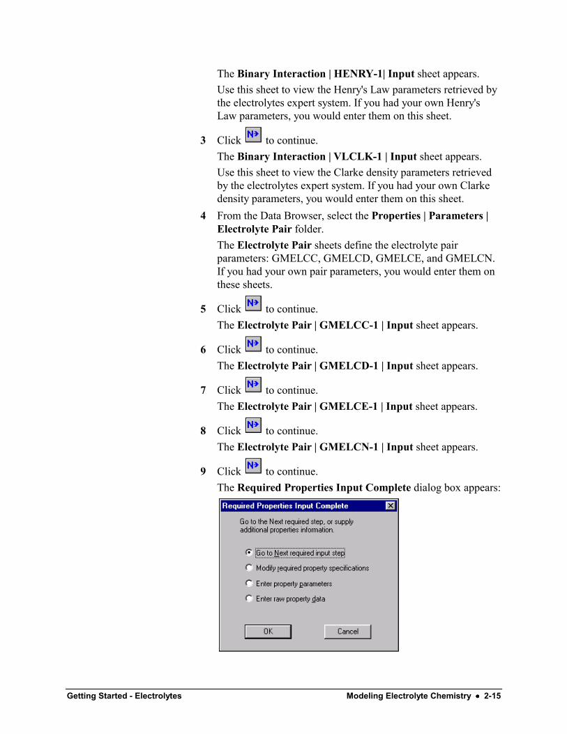
9 Click to continue.The Required Properties Input Complete dialog box appears:

2-16 •••• Modeling Electrolyte Chemistry Getting Started - Electrolytes
Correct representation of physical properties is essential toprocess modeling. For many simulations, the only physicalproperty specification that you must provide is the selection ofa property method. This dialog box shows that the Aspen Plusphysical property system has many optional capabilities toincrease the accuracy of the physical property calculations.Because the Aspen Plus electrolytes database has data for allcomponents and pairs in this simulation, you don't need toprovide any optional specifications or data.Now that the Components and Properties specifications arecomplete, complete the rest of the flowsheet specifications inthe same way as for nonelectrolytes. There are no stream orblock restrictions in using Aspen Plus electrolytes. You can useall Aspen Plus unit operation models in an electrolytessimulation.
10 Click OK to move to the next required input.
Entering Stream DataThe Streams | HCL | Input | Specifications sheet appears. AspenPlus requires two thermodynamic specifications and enoughinformation to calculate the flow rate of each component.1 On the Streams HCL Input Specifications sheet, enter the
following:Temperature 25 C
Pressure 1 bar
WATER flow value 10 kmol/hr
HCL flow value 1 kmol/hr
You entered the flow specifications for this stream in terms ofthe base components (the apparent components). Although youare using the true component approach in this simulation,Aspen Plus can accept stream specifications in terms of theapparent components as well as the true components. AspenPlus converts the apparent component flow specifications totrue component specifications.
2 Click to continue.

Getting Started - Electrolytes Modeling Electrolyte Chemistry •••• 2-17
The Streams | NAOH | Input | Specifications sheet appears.3 Enter the following data
Temperature 25 C
Pressure 1 Bar
WATER flow value 10 kmol/hr
NAOH flow value 1.1 kmol/hr
4 Click to continue.
Specifying the Flash BlockThe Blocks | FLASH | Input | Specifications sheet appears. Forthis simulation, specify the pressure drop and vapor fraction.
1 In the Temperature field, click , select Vapor fraction, andthen enter 0.75.
2 In the Pressure field, enter 0 (indicating there is no pressuredrop).
3 Click to continue.The Blocks | MIX | Input | Flash Options sheet appears. Asthe prompt says, the zero default pressure indicates no pressuredrop, which is correct for this simulation.
4 Click to continue.The Required Input Complete dialog box appears informingyou that all required input is complete and asking if you wantto run the simulation.Before running the simulation, request that certain optionalproperties be included in the stream report.
5 Click Cancel to close the dialog box without running thesimulation.
Specifying Additional StreamPropertiesBy default, the only component properties that Aspen Pluscalculates and reports for this simulation are component massflows. Since you are using the true component approach, thecomponent flows will be in terms of the components actuallypresent at equilibrium, not the apparent (base) components.

2-18 •••• Modeling Electrolyte Chemistry Getting Started - Electrolytes
1 From the Data Browser, select the Setup folder and then selectReport Options.
2 Select the Stream tab.On the Setup | Report Options | Stream sheet, you specify thestream properties to be calculated and reported. For thissimulation, request that component mass fractions becalculated and reported.
3 Under Fraction Basis, select the Mass checkbox .You can also define additional stream properties to becalculated and reported, using Aspen Plus property sets. AspenPlus provides a number of built-in property sets based on theApplication Type you selected. You can also define your ownproperty sets. In this simulation, you will use a built-in propertyset to report the bubble point of each stream, and a secondbuilt-in property set to report the mass fractions of the apparentcomponents in each stream.
4 Click Property Sets.The Property Sets dialog box appears.
5 From the Available Property Sets column, select TBUBBLEand WXAPP.
6 Click to move the selected property sets to the SelectedProperty Sets column.
7 Click Close.
8 Click to continue.
To Specify AdditionalProperties
Getting Started - Electrolytes Modeling Electrolyte Chemistry •••• 2-19
Running the SimulationThe Required Input Complete dialog box appears.1 Click OK to run the simulation.
The Control Panel appears.As the run proceeds, status messages appear in the ControlPanel.Aspen Plus has a special databank it searches only when youuse the ELECNRTL option set, as in this simulation. Somephysical property parameters in this databank may be differentfrom the parameters in the standard non-electrolyte databanks.The values of the physical property parameters in the specialdatabank were determined to provide a better fit for electrolytesystems, and are not generally applicable.When values are retrieved from this special databank, AspenPlus generates messages in the Control Panel to inform youwhat properties are retrieved for which components.
2 Use the vertical scrollbar to the right of the Control Panelwindow to see the messages.When the calculations finish, the message Results Availableappears in the status area at the bottom right of the mainwindow.
3 Examine the results of your run.
Examining Simulation Results1 From the Control Panel, click .
The Results Summary | Run Status | Summary sheetappears, indicating that the simulation completed normally.
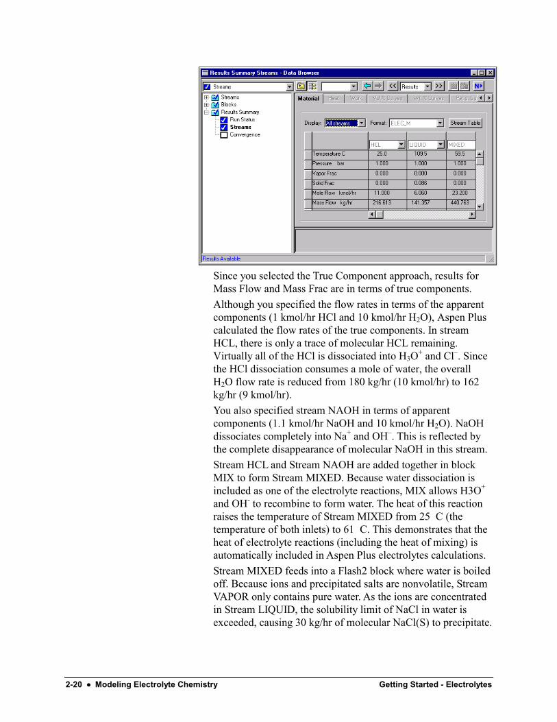
2 Click in the Data Browser toolbar to move to the nextresults sheet.The Results Summary | Streams | Material sheet appears.
3 Review the results on this sheet.4 Use the horizontal and vertical scrollbars to review results that
are off the screen.
2-20 •••• Modeling Electrolyte Chemistry Getting Started - Electrolytes
Since you selected the True Component approach, results forMass Flow and Mass Frac are in terms of true components.Although you specified the flow rates in terms of the apparentcomponents (1 kmol/hr HCl and 10 kmol/hr H2O), Aspen Pluscalculated the flow rates of the true components. In streamHCL, there is only a trace of molecular HCL remaining.Virtually all of the HCl is dissociated into H3O+ and Cl–. Sincethe HCl dissociation consumes a mole of water, the overallH2O flow rate is reduced from 180 kg/hr (10 kmol/hr) to 162kg/hr (9 kmol/hr).You also specified stream NAOH in terms of apparentcomponents (1.1 kmol/hr NaOH and 10 kmol/hr H2O). NaOHdissociates completely into Na+ and OH–. This is reflected bythe complete disappearance of molecular NaOH in this stream.Stream HCL and Stream NAOH are added together in blockMIX to form Stream MIXED. Because water dissociation isincluded as one of the electrolyte reactions, MIX allows H3O+
and OH- to recombine to form water. The heat of this reactionraises the temperature of Stream MIXED from 25 C (thetemperature of both inlets) to 61 C. This demonstrates that theheat of electrolyte reactions (including the heat of mixing) isautomatically included in Aspen Plus electrolytes calculations.Stream MIXED feeds into a Flash2 block where water is boiledoff. Because ions and precipitated salts are nonvolatile, StreamVAPOR only contains pure water. As the ions are concentratedin Stream LIQUID, the solubility limit of NaCl in water isexceeded, causing 30 kg/hr of molecular NaCl(S) to precipitate.
Getting Started - Electrolytes Modeling Electrolyte Chemistry •••• 2-21
Examine the bubble temperature for stream MIXED and streamLIQUID. Stream MIXED is subsaturated in NACL and streamLIQUID is saturated with NACL. Aspen Plus correctlycalculates the bubble point of LIQUID (109 C) as greater thanthe bubble point of MIXED (103 C), which is greater than theboiling point of pure water at 1 bar (99.6 C).Compare the apparent mass fractions for the liquid phase withthe true component mass fractions in stream LIQUID. Eventhough stream LIQUID has precipitated NaCl(S), the apparentmass fraction of NaCl(S) is zero because Aspen Plus does notconsider precipitated salts to be apparent components. Theapparent mass fractions of the ions Na+, H3O+, OH–, and Cl–
are also zero. Precipitated salts and ions can only be truecomponents.Since the precipitated NaCl(S) is not an apparent component, itis represented in the apparent component approach in terms ofthe original species that combined to form NaCl(S): NaOH,and HCl. This is why the apparent component basis massfraction of NaOH is 0.209 even though the true componentbasis mass fraction of NAOH is zero.You have now viewed the most relevant results for anelectrolytes simulation.
5 This simulation has other Results sheets. Click to viewthem, if you choose.
Exiting Aspen Plus1 From the Aspen Plus menu, select File and then select Exit.
The Aspen Plus dialog box appears.2 Click No.
– or –Click Yes if you want to save the run, and enter a Run ID whenprompted.This simulation (using the apparent approach) is delivered asbackup file elec1 in the Aspen Plus Examples Library. Use thisbackup file to check your results.

2-22 •••• Modeling Electrolyte Chemistry Getting Started - Electrolytes
Getting Started - Electrolytes Modeling a Sour Water Stripper •••• 3-1
Modeling a Sour Water Stripper
In this simulation, use a distillation column to strip NH3 and H2Sfrom a sour water feed stream.
You will:• Modify the generated Chemistry• Use the apparent component approach for electrolytes• Define a stream property (Property Set)• Convert the simulation from the apparent approach to the true
approach
Allow about 45 minutes to do this simulation.
3-2 •••• Modeling a Sour Water Stripper Getting Started - Electrolytes
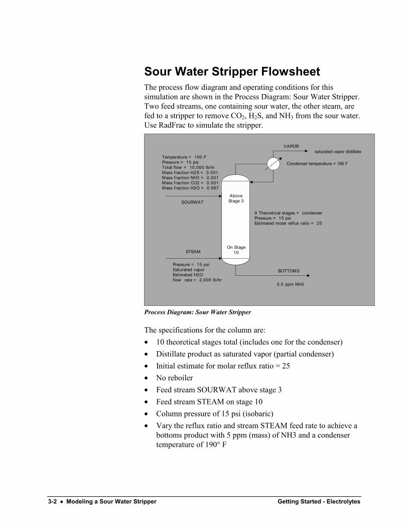
Sour Water Stripper FlowsheetThe process flow diagram and operating conditions for thissimulation are shown in the Process Diagram: Sour Water Stripper.Two feed streams, one containing sour water, the other steam, arefed to a stripper to remove CO2, H2S, and NH3 from the sour water.Use RadFrac to simulate the stripper.
SOURWAT
STEAM
BOTTOMS
VAPOR
Temperature = 190 FPressure = 15 psiTotal f low = 10,000 lb/hrMass fraction H2S = 0.001Mass fraction NH3 = 0.001Mass fraction CO2 = 0.001Mass fraction H2O = 0.997
Pressure = 15 psiSaturated vaporEst imated H2O f low rate = 2,000 lb/hr
AboveStage 3
On Stage10
5.0 ppm NH3
9 Theoret ical stages + condenserPressure = 15 psiEst imated molar ref lux ratio = 25
Condenser temperature = 190 F
saturated vapor distillate
Process Diagram: Sour Water Stripper
The specifications for the column are:• 10 theoretical stages total (includes one for the condenser)• Distillate product as saturated vapor (partial condenser)• Initial estimate for molar reflux ratio = 25• No reboiler• Feed stream SOURWAT above stage 3• Feed stream STEAM on stage 10• Column pressure of 15 psi (isobaric)• Vary the reflux ratio and stream STEAM feed rate to achieve a
bottoms product with 5 ppm (mass) of NH3 and a condensertemperature of 190° F
Getting Started - Electrolytes Modeling a Sour Water Stripper •••• 3-3
Starting Aspen Plus1 From your desktop, select Start and then select Programs.2 Select AspenTech | Aspen Engineering Suite | Aspen Plus
11.1 | Aspen Plus User Interface.
The Aspen Plus Startup dialog box appears. Aspen Plus displaysa dialog box whenever you must enter information or make aselection before proceeding. In this simulation, use an Aspen Plustemplate.1 Select the Template radio button and click OK.
The New dialog box appears.2 Use the New dialog box to specify the application type and the
run type for the new run. Aspen Plus uses the application typeyou choose to automatically set various defaults appropriate toyour application.
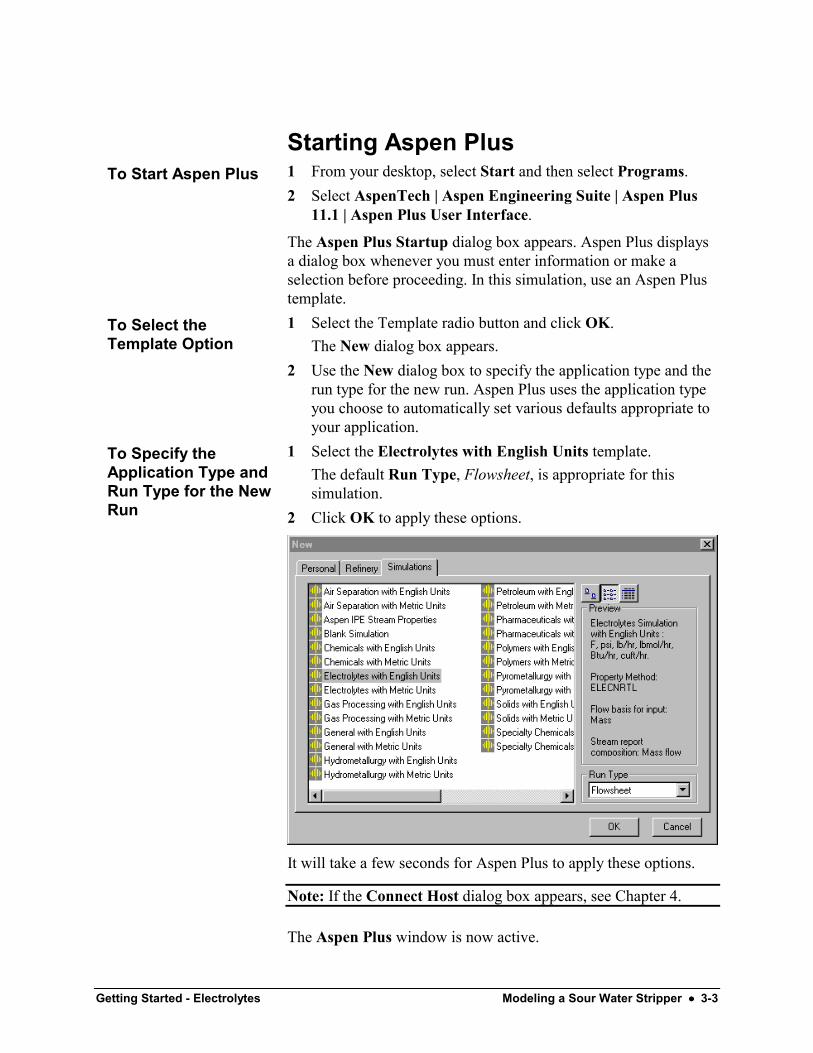
1 Select the Electrolytes with English Units template.The default Run Type, Flowsheet, is appropriate for thissimulation.
2 Click OK to apply these options.
It will take a few seconds for Aspen Plus to apply these options.
Note: If the Connect Host dialog box appears, see Chapter 4.
The Aspen Plus window is now active.
To Start Aspen Plus
To Select theTemplate Option
To Specify theApplication Type andRun Type for the NewRun

3-4 •••• Modeling a Sour Water Stripper Getting Started - Electrolytes
Drawing the Graphical SimulationFlowsheetIn this simulation, begin to build the process flowsheet. Since youwill enter your own block and stream IDs, turn off the defaultCreate auto block ID and Create auto stream ID options, whichprovide these IDs automatically.1 From the Aspen Plus menu bar, select Tools | Options.
The Options dialog box appears.2 Select the Flowsheet tab.3 Clear the Automatically Assign Block Name with Prefix and
the Automatically Assign Stream Name with Prefix options.
4 Click OK to close the Options dialog box and apply thechanges.

Getting Started - Electrolytes Modeling a Sour Water Stripper •••• 3-5
5 Place a RadFrac blocks and streams to create the graphicalsimulation flowsheet as follows:
Note that the distillate stream is connected to the VaporDistillate port.
6 Click to guide you to the next required input.The Flowsheet Complete dialog box appears.
7 Click OK to continue.
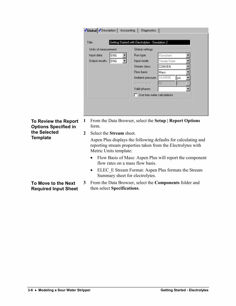
Specifying Title, Stream Properties,and Global OptionsThe Data Browser window appears. The Setup | Specifications |Global sheet displays default Aspen Plus settings and units usedfor other sheets.
Use this sheet to give your simulation a title, and to review thestream properties and global options that were set when youselected the Electrolytes with English Units application type.
The Run type field displays Flowsheet, which is appropriate forthis simulation.
The Electrolytes with English Units application type sets thefollowing global defaults for electrolytes applications:• ENG units (English units)• Mass Flow basis for all flow inputs
It is always good practice to enter a title for the simulation.
In the Title field, enter Getting Started with Electrolytes -Simulation 2.
3-6 •••• Modeling a Sour Water Stripper Getting Started - Electrolytes
1 From the Data Browser, select the Setup | Report Optionsform.
2 Select the Stream sheet.Aspen Plus displays the following defaults for calculating andreporting stream properties taken from the Electrolytes withMetric Units template:• Flow Basis of Mass: Aspen Plus will report the component
flow rates on a mass flow basis.• ELEC_E Stream Format: Aspen Plus formats the Stream
Summary sheet for electrolytes.3 From the Data Browser, select the Components folder and
then select Specifications.
To Review the ReportOptions Specified inthe SelectedTemplate
To Move to the NextRequired Input Sheet
Getting Started - Electrolytes Modeling a Sour Water Stripper •••• 3-7
Specifying ComponentsThe Components Specifications Selection sheet appears.
The apparent (or base) components for this simulation are H2O,NH3, H2S, and CO2. Because you chose an electrolytes ApplicationType, water already appears on the sheet.1 Enter the following components in addition to the predefined
water:NH3 AmmoniaH2S Hydrogen-SulfideCO2 Carbon-Dioxide
Because the formula for ammonia is represented as H3N in theAspen Plus databank, you must identify NH3 by entering eitherthe Component name (ammonia) or the Formula (H3N).
2 Click Elec Wizard.The Electrolyte Wizard dialog box, for defining automaticchemistry generation, appears.
The Electrolyte WizardUse the Electrolyte Wizard dialog box to define the ionic speciesthat can be generated from the base components you specified onthe Components | Specifications| Selection sheet, and to generatethe reactions that occur among these components in the liquidphase.
1 On the Electrolyte Wizard dialog box, click .
2 Click to move all components in the Availablecomponents column to the Selected components column.
3 Click to continue.
3-8 •••• Modeling a Sour Water Stripper Getting Started - Electrolytes
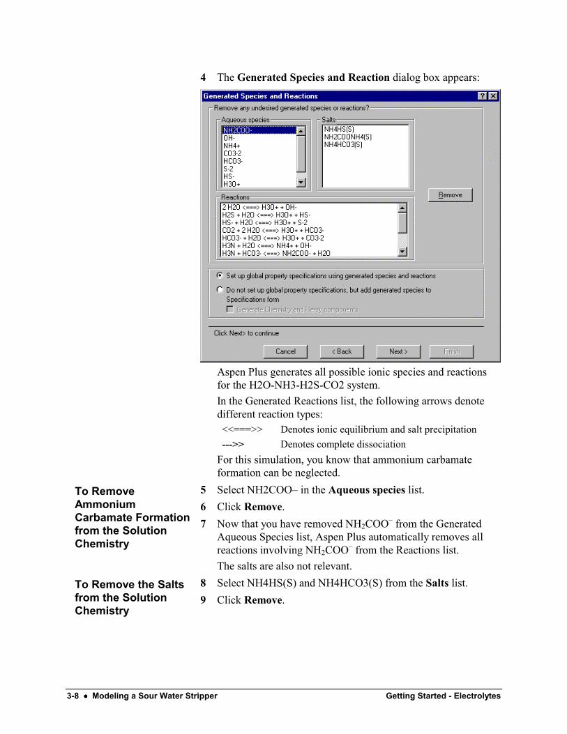
4 The Generated Species and Reaction dialog box appears:
Aspen Plus generates all possible ionic species and reactionsfor the H2O-NH3-H2S-CO2 system.In the Generated Reactions list, the following arrows denotedifferent reaction types:<<===>> Denotes ionic equilibrium and salt precipitation--->> Denotes complete dissociation
For this simulation, you know that ammonium carbamateformation can be neglected.
5 Select NH2COO– in the Aqueous species list.6 Click Remove.7 Now that you have removed NH2COO– from the Generated
Aqueous Species list, Aspen Plus automatically removes allreactions involving NH2COO– from the Reactions list.The salts are also not relevant.
8 Select NH4HS(S) and NH4HCO3(S) from the Salts list.9 Click Remove.
To RemoveAmmoniumCarbamate Formationfrom the SolutionChemistry
To Remove the Saltsfrom the SolutionChemistry
Getting Started - Electrolytes Modeling a Sour Water Stripper •••• 3-9
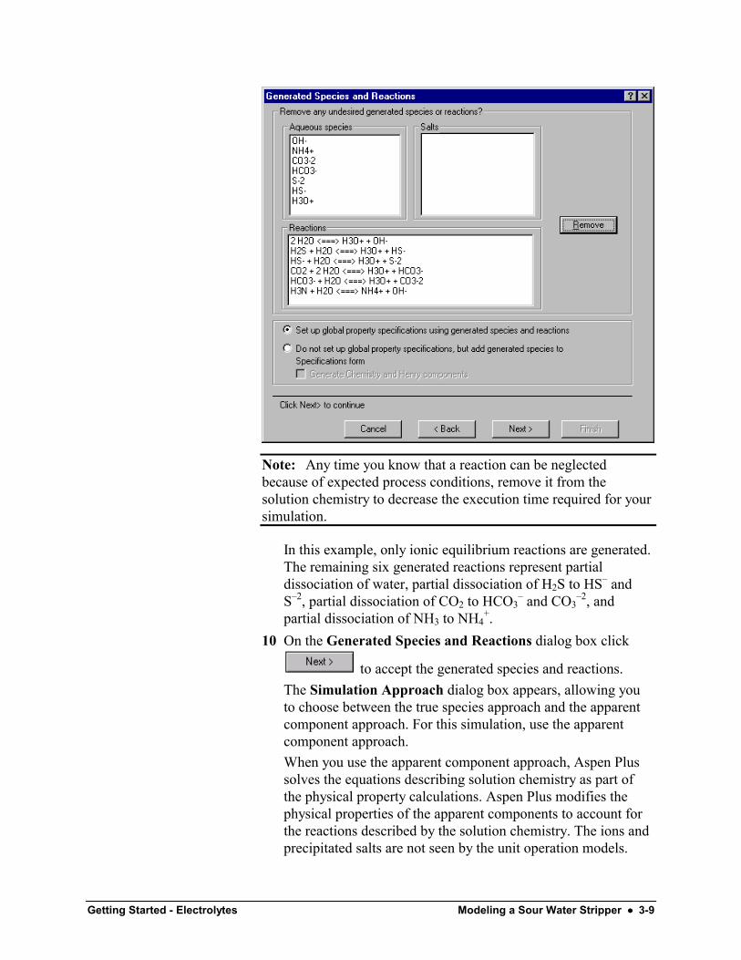
Note: Any time you know that a reaction can be neglectedbecause of expected process conditions, remove it from thesolution chemistry to decrease the execution time required for yoursimulation.
In this example, only ionic equilibrium reactions are generated.The remaining six generated reactions represent partialdissociation of water, partial dissociation of H2S to HS– andS–2, partial dissociation of CO2 to HCO3
– and CO3–2, and
partial dissociation of NH3 to NH4+.
10 On the Generated Species and Reactions dialog box click
to accept the generated species and reactions.The Simulation Approach dialog box appears, allowing youto choose between the true species approach and the apparentcomponent approach. For this simulation, use the apparentcomponent approach.When you use the apparent component approach, Aspen Plussolves the equations describing solution chemistry as part ofthe physical property calculations. Aspen Plus modifies thephysical properties of the apparent components to account forthe reactions described by the solution chemistry. The ions andprecipitated salts are not seen by the unit operation models.
3-10 •••• Modeling a Sour Water Stripper Getting Started - Electrolytes
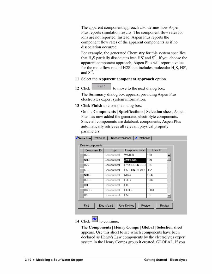
The apparent component approach also defines how AspenPlus reports simulation results. The component flow rates forions are not reported. Instead, Aspen Plus reports thecomponent flow rates of the apparent components as if nodissociation occurred.For example, the generated Chemistry for this system specifiesthat H2S partially dissociates into HS- and S-2. If you choose theapparent component approach, Aspen Plus will report a valuefor the mole flow rate of H2S that includes molecular H2S, HS-,and S-2.
11 Select the Apparent component approach option.
12 Click to move to the next dialog box.The Summary dialog box appears, providing Aspen Pluselectrolytes expert system information.
13 Click Finish to close the dialog box.On the Components | Specifications | Selection sheet, AspenPlus has now added the generated electrolyte components.Since all components are databank components, Aspen Plusautomatically retrieves all relevant physical propertyparameters.
14 Click to continue.The Components | Henry Comps | Global | Selection sheetappears. Use this sheet to see which components have beendeclared as Henry's Law components by the electrolytes expertsystem in the Henry Comps group it created, GLOBAL. If you

Getting Started - Electrolytes Modeling a Sour Water Stripper •••• 3-11
had additional Henry's Law components in your simulation(such as nitrogen and oxygen), you could add them to the liston this sheet.
Examining Generated ChemistryIn the previous step, the Aspen Plus Electrolyte Wizardautomatically generated the chemistry definition for yoursimulation and named it GLOBAL.1 From the Data Browser, select the Reactions folder.2 From the Reactions folder, select the Chemistry | Global.
The Reactions | Chemistry | Global | Stoichiometry sheetappears.
1 Select a Reaction and click Edit.The Equilibrium Reaction Stoichiometry dialog box appears,with the data for the selected reaction that was generated by theElectrolytes Wizard.
2 Close the dialog box and view the other reactions using thesame steps.
3 Click the Equilibrium Constants tab. Select the variousreactions in the Equilibrium reaction field. All six reactionshave equilibrium constants that have been retrieved from theAspen Plus reactions database.
4 From the Data Browser, select the Properties folder and thenselect Specifications.
To Examine theGenerated Chemistry
To View theGenerated Chemistry
3-12 •••• Modeling a Sour Water Stripper Getting Started - Electrolytes
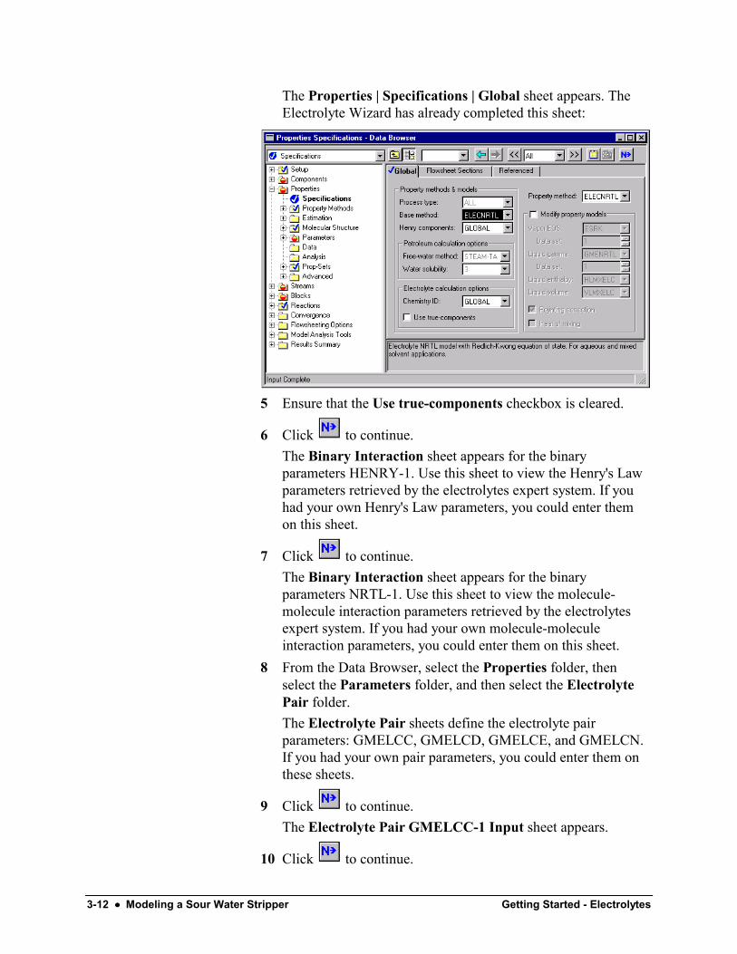
The Properties | Specifications | Global sheet appears. TheElectrolyte Wizard has already completed this sheet:
5 Ensure that the Use true-components checkbox is cleared.
6 Click to continue.The Binary Interaction sheet appears for the binaryparameters HENRY-1. Use this sheet to view the Henry's Lawparameters retrieved by the electrolytes expert system. If youhad your own Henry's Law parameters, you could enter themon this sheet.
7 Click to continue.The Binary Interaction sheet appears for the binaryparameters NRTL-1. Use this sheet to view the molecule-molecule interaction parameters retrieved by the electrolytesexpert system. If you had your own molecule-moleculeinteraction parameters, you could enter them on this sheet.
8 From the Data Browser, select the Properties folder, thenselect the Parameters folder, and then select the ElectrolytePair folder.The Electrolyte Pair sheets define the electrolyte pairparameters: GMELCC, GMELCD, GMELCE, and GMELCN.If you had your own pair parameters, you could enter them onthese sheets.
9 Click to continue.The Electrolyte Pair GMELCC-1 Input sheet appears.
10 Click to continue.
Getting Started - Electrolytes Modeling a Sour Water Stripper •••• 3-13
The Electrolyte Pair GMELCD-1 Input sheet appears.
11 Click to continue.The Electrolyte Pair GMELCE-1 Input sheet appears.
12 Click to continue.The Electrolyte Pair GMELCN-1 Input sheet appears.
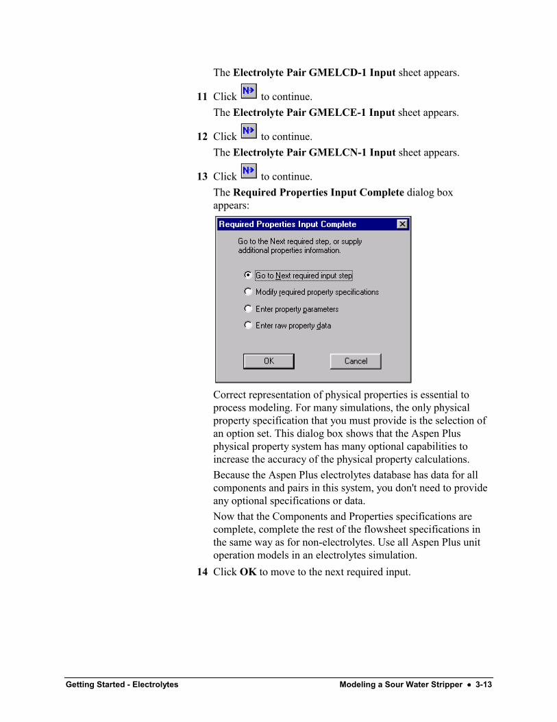
13 Click to continue.The Required Properties Input Complete dialog boxappears:
Correct representation of physical properties is essential toprocess modeling. For many simulations, the only physicalproperty specification that you must provide is the selection ofan option set. This dialog box shows that the Aspen Plusphysical property system has many optional capabilities toincrease the accuracy of the physical property calculations.Because the Aspen Plus electrolytes database has data for allcomponents and pairs in this system, you don't need to provideany optional specifications or data.Now that the Components and Properties specifications arecomplete, complete the rest of the flowsheet specifications inthe same way as for non-electrolytes. Use all Aspen Plus unitoperation models in an electrolytes simulation.
14 Click OK to move to the next required input.
3-14 •••• Modeling a Sour Water Stripper Getting Started - Electrolytes
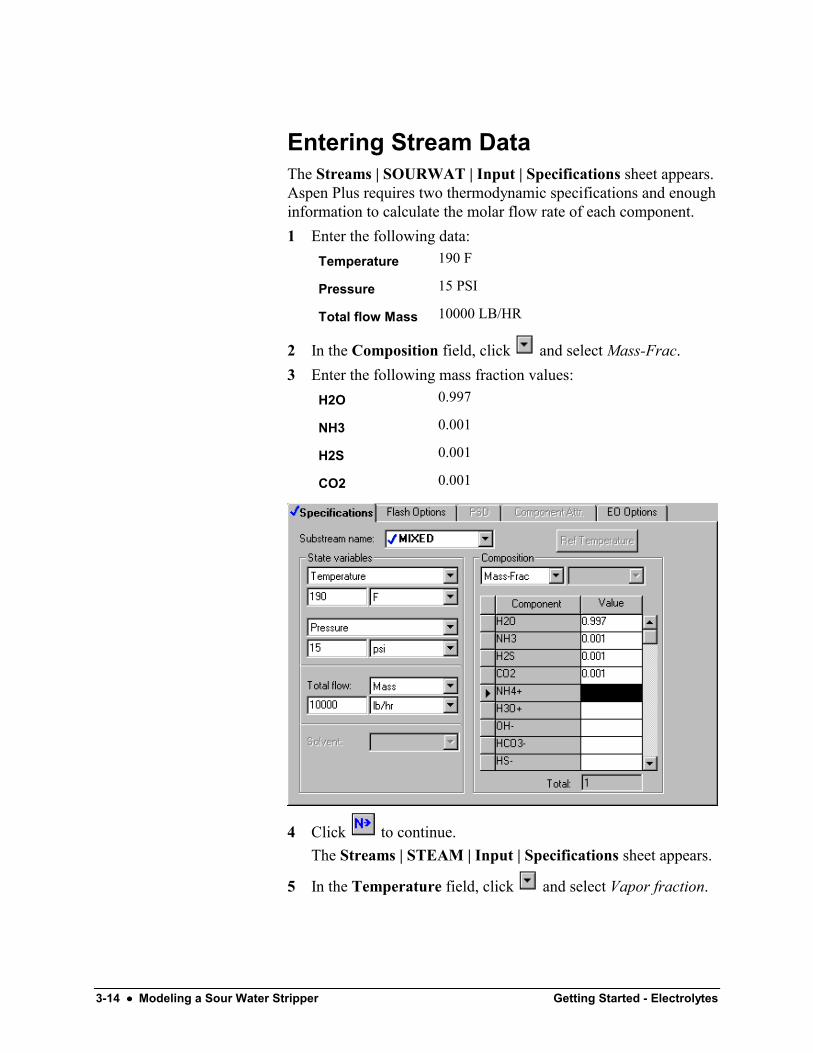
Entering Stream DataThe Streams | SOURWAT | Input | Specifications sheet appears.Aspen Plus requires two thermodynamic specifications and enoughinformation to calculate the molar flow rate of each component.1 Enter the following data:
Temperature 190 F
Pressure 15 PSI
Total flow Mass 10000 LB/HR
2 In the Composition field, click and select Mass-Frac.3 Enter the following mass fraction values:
H2O 0.997
NH3 0.001
H2S 0.001
CO2 0.001
4 Click to continue.The Streams | STEAM | Input | Specifications sheet appears.
5 In the Temperature field, click and select Vapor fraction.
Getting Started - Electrolytes Modeling a Sour Water Stripper •••• 3-15
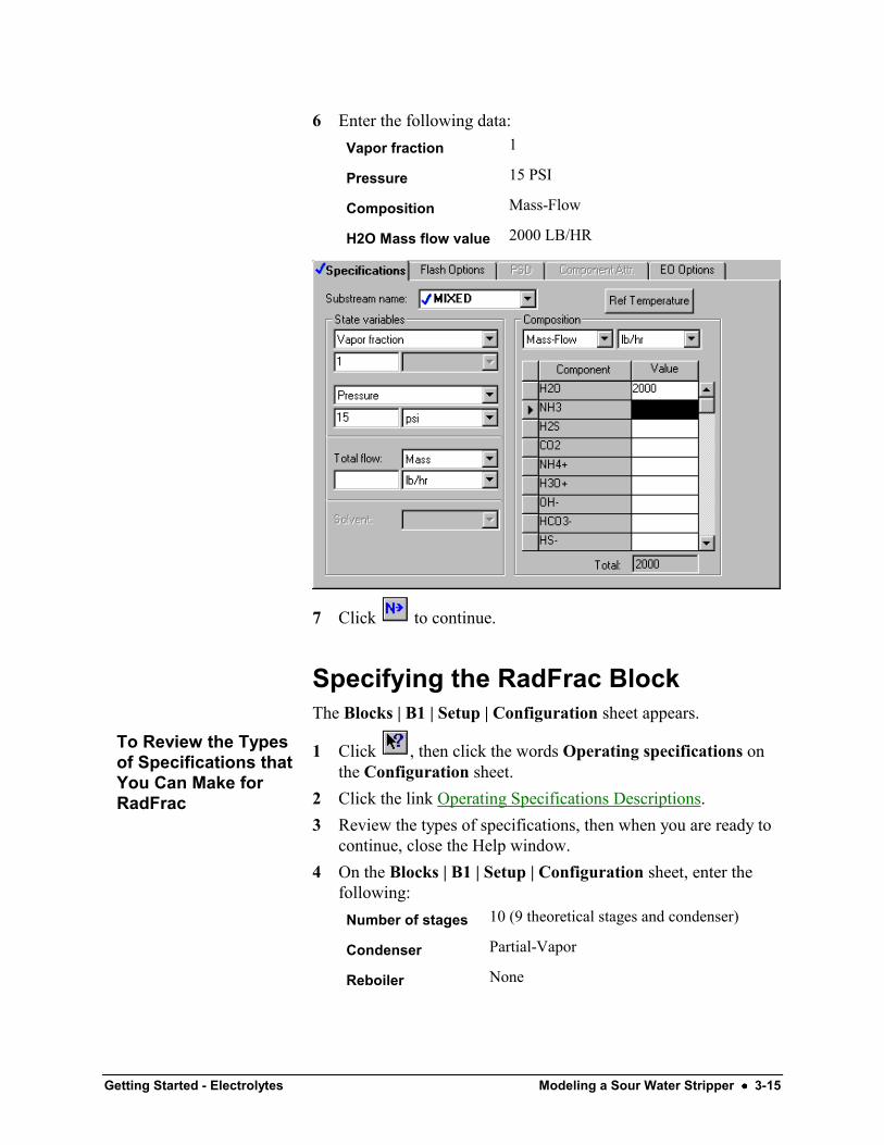
6 Enter the following data:Vapor fraction 1
Pressure 15 PSI
Composition Mass-Flow
H2O Mass flow value 2000 LB/HR
7 Click to continue.
Specifying the RadFrac BlockThe Blocks | B1 | Setup | Configuration sheet appears.
1 Click , then click the words Operating specifications onthe Configuration sheet.
2 Click the link Operating Specifications Descriptions.3 Review the types of specifications, then when you are ready to
continue, close the Help window.4 On the Blocks | B1 | Setup | Configuration sheet, enter the
following:Number of stages 10 (9 theoretical stages and condenser)
Condenser Partial-Vapor
Reboiler None
To Review the Typesof Specifications thatYou Can Make forRadFrac
3-16 •••• Modeling a Sour Water Stripper Getting Started - Electrolytes
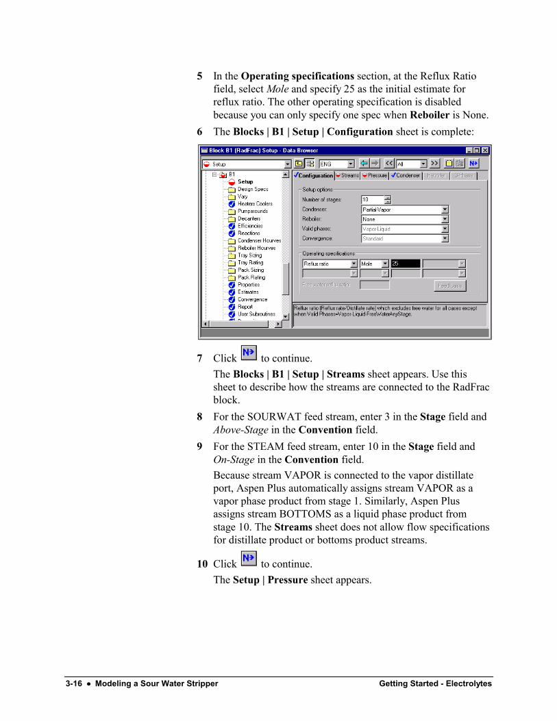
5 In the Operating specifications section, at the Reflux Ratiofield, select Mole and specify 25 as the initial estimate forreflux ratio. The other operating specification is disabledbecause you can only specify one spec when Reboiler is None.
6 The Blocks | B1 | Setup | Configuration sheet is complete:
7 Click to continue.The Blocks | B1 | Setup | Streams sheet appears. Use thissheet to describe how the streams are connected to the RadFracblock.
8 For the SOURWAT feed stream, enter 3 in the Stage field andAbove-Stage in the Convention field.
9 For the STEAM feed stream, enter 10 in the Stage field andOn-Stage in the Convention field.Because stream VAPOR is connected to the vapor distillateport, Aspen Plus automatically assigns stream VAPOR as avapor phase product from stage 1. Similarly, Aspen Plusassigns stream BOTTOMS as a liquid phase product fromstage 10. The Streams sheet does not allow flow specificationsfor distillate product or bottoms product streams.
10 Click to continue.The Setup | Pressure sheet appears.
Getting Started - Electrolytes Modeling a Sour Water Stripper •••• 3-17
1 In the Stage 1 / Condenser pressure field, enter 15 psi.
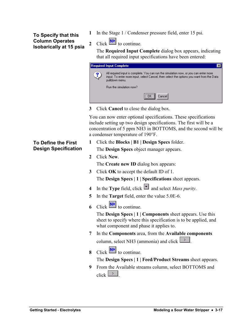
2 Click to continue.The Required Input Complete dialog box appears, indicatingthat all required input specifications have been entered:
3 Click Cancel to close the dialog box.
You can now enter optional specifications. These specificationsinclude setting up two design specifications. The first will be aconcentration of 5 ppm NH3 in BOTTOMS, and the second will bea condenser temperature of 190°F.1 Click the Blocks | B1 | Design Specs folder.
The Design Specs object manager appears.2 Click New.
The Create new ID dialog box appears:3 Click OK to accept the default ID of 1.
The Design Specs | 1 | Specifications sheet appears.
4 In the Type field, click and select Mass purity.5 In the Target field, enter the value 5.0E-6.
6 Click to continue.The Design Specs | 1 | Components sheet appears. Use thissheet to specify where this specification is to be applied, andwhat component and phase it applies to.
7 In the Components area, from the Available componentscolumn, select NH3 (ammonia) and click .
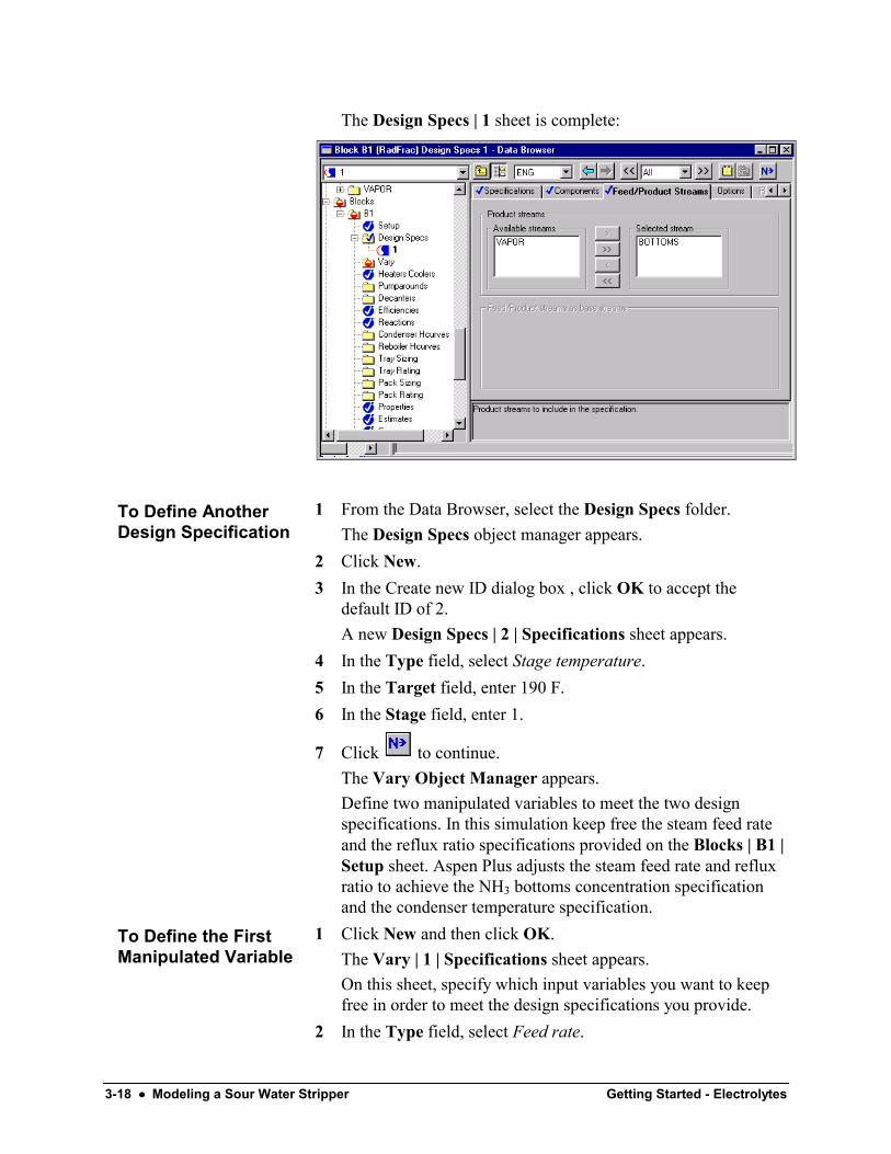
8 Click to continue.The Design Specs | 1 | Feed/Product Streams sheet appears.
9 From the Available streams column, select BOTTOMS andclick .
To Specify that thisColumn OperatesIsobarically at 15 psia
To Define the FirstDesign Specification
3-18 •••• Modeling a Sour Water Stripper Getting Started - Electrolytes
The Design Specs | 1 sheet is complete:
1 From the Data Browser, select the Design Specs folder.The Design Specs object manager appears.
2 Click New.3 In the Create new ID dialog box , click OK to accept the
default ID of 2.A new Design Specs | 2 | Specifications sheet appears.
4 In the Type field, select Stage temperature.5 In the Target field, enter 190 F.6 In the Stage field, enter 1.
7 Click to continue.The Vary Object Manager appears.Define two manipulated variables to meet the two designspecifications. In this simulation keep free the steam feed rateand the reflux ratio specifications provided on the Blocks | B1 |Setup sheet. Aspen Plus adjusts the steam feed rate and refluxratio to achieve the NH3 bottoms concentration specificationand the condenser temperature specification.
1 Click New and then click OK.The Vary | 1 | Specifications sheet appears.On this sheet, specify which input variables you want to keepfree in order to meet the design specifications you provide.
2 In the Type field, select Feed rate.
To Define AnotherDesign Specification
To Define the FirstManipulated Variable

Getting Started - Electrolytes Modeling a Sour Water Stripper •••• 3-19
3 In the Stream name field, select STEAM.4 In the Lower bound field, enter 50 lbmol/hr.5 In the Upper bound field, enter 200 lbmol/hr.
On the Streams | STEAM form you specified a Mass-Flow forstream STEAM. However, when you select the variable typeFeed rate on the Vary form, Aspen Plus assumes the Feed rateto be on a mole basis. In this case, varying the Feed rate on amole basis from 50-200 (lbmol/hr) is equivalent to varying theMass flow from 900-3600 (lb/hr).
1 From the Data Browser, select the Vary folder.2 Click New and then click OK.3 In the Type field, select Reflux ratio.4 In the Lower bound field, enter 15.5 In the Upper bound field, enter 50.
As with Feed rate, Aspen Plus always varies the reflux ratio ona mole basis, even if you specify a mass reflux ratio on theBlocks | B1 | Setup form.
6 Click to continue.The Required Input Complete dialog box appears, indicatingthat all required specifications are complete.
7 Click Cancel.
To Define the SecondManipulated Variable
3-20 •••• Modeling a Sour Water Stripper Getting Started - Electrolytes
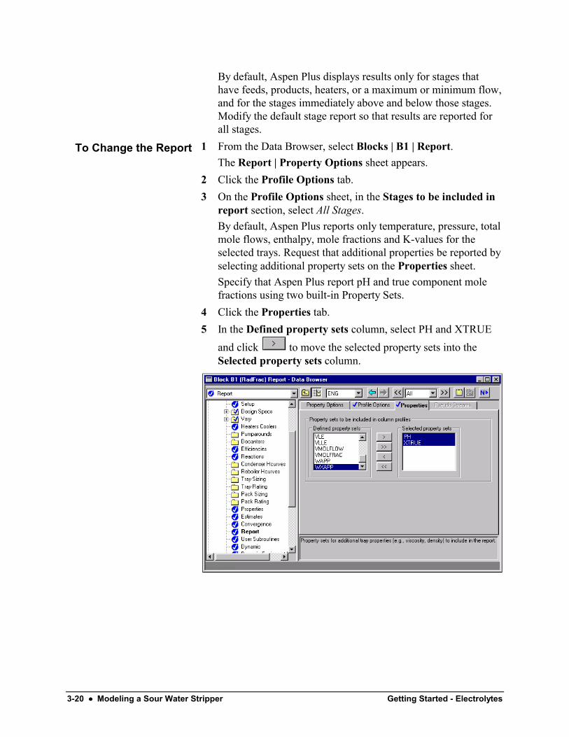
By default, Aspen Plus displays results only for stages thathave feeds, products, heaters, or a maximum or minimum flow,and for the stages immediately above and below those stages.Modify the default stage report so that results are reported forall stages.
1 From the Data Browser, select Blocks | B1 | Report.The Report | Property Options sheet appears.
2 Click the Profile Options tab.3 On the Profile Options sheet, in the Stages to be included in
report section, select All Stages.By default, Aspen Plus reports only temperature, pressure, totalmole flows, enthalpy, mole fractions and K-values for theselected trays. Request that additional properties be reported byselecting additional property sets on the Properties sheet.Specify that Aspen Plus report pH and true component molefractions using two built-in Property Sets.
4 Click the Properties tab.5 In the Defined property sets column, select PH and XTRUE
and click to move the selected property sets into theSelected property sets column.
To Change the Report
Getting Started - Electrolytes Modeling a Sour Water Stripper •••• 3-21
Running the Simulation1 Click to continue.
The Required Input Complete dialog box appears.2 Click OK to run the simulation.
The Control Panel appears.As the run proceeds, messages appear in the Control Panel. Ittakes a few moments for Aspen Plus to process inputspecifications and perform the simulation.As in simulation 1, Aspen Plus displays messages indicatingthat some properties have been retrieved from a specialdatabank.When the calculations finish, the message Results Availableappears in the status area at the right of the main windowtoolbar.
3 When the message Results Available appears in the status bar,
click to view the results of your run.
3-22 •••• Modeling a Sour Water Stripper Getting Started - Electrolytes
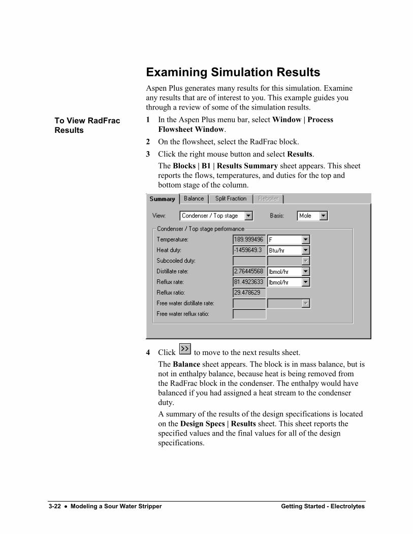
Examining Simulation ResultsAspen Plus generates many results for this simulation. Examineany results that are of interest to you. This example guides youthrough a review of some of the simulation results.1 In the Aspen Plus menu bar, select Window | Process
Flowsheet Window.2 On the flowsheet, select the RadFrac block.3 Click the right mouse button and select Results.
The Blocks | B1 | Results Summary sheet appears. This sheetreports the flows, temperatures, and duties for the top andbottom stage of the column.
4 Click to move to the next results sheet.The Balance sheet appears. The block is in mass balance, but isnot in enthalpy balance, because heat is being removed fromthe RadFrac block in the condenser. The enthalpy would havebalanced if you had assigned a heat stream to the condenserduty.A summary of the results of the design specifications is locatedon the Design Specs | Results sheet. This sheet reports thespecified values and the final values for all of the designspecifications.
To View RadFracResults
Getting Started - Electrolytes Modeling a Sour Water Stripper •••• 3-23
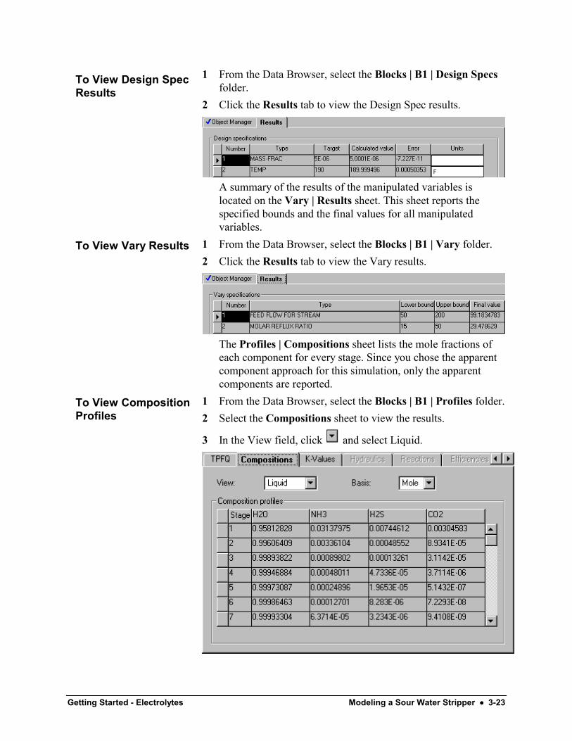
1 From the Data Browser, select the Blocks | B1 | Design Specsfolder.
2 Click the Results tab to view the Design Spec results.
A summary of the results of the manipulated variables islocated on the Vary | Results sheet. This sheet reports thespecified bounds and the final values for all manipulatedvariables.
1 From the Data Browser, select the Blocks | B1 | Vary folder.2 Click the Results tab to view the Vary results.
The Profiles | Compositions sheet lists the mole fractions ofeach component for every stage. Since you chose the apparentcomponent approach for this simulation, only the apparentcomponents are reported.
1 From the Data Browser, select the Blocks | B1 | Profiles folder.2 Select the Compositions sheet to view the results.
3 In the View field, click and select Liquid.
To View Design SpecResults
To View Vary Results
To View CompositionProfiles

3-24 •••• Modeling a Sour Water Stripper Getting Started - Electrolytes
The Profiles | Properties sheet reports the actual compositionof molecular components and ions.
1 Select the Properties sheet. You may need to click the arrowsat the right end of the row of tabs to reach it.
Consider the results for Stage 1. The true composition of NH3and NH4+ sum to 0.03147 on Stage 1. This value is slightlydifferent from the apparent mole fraction of NH3 reported onthe Compositions sheet: 0.03138. This slight difference iscaused by the solution chemistry.In general, the total number of moles is not conserved bysolution chemistry. In this simulation, the fourth equilibriumreaction consumes 3 moles of reactants and generates twomoles of products:
−+ +⇔+ 3322 2 HCOOHOHCO
The total number moles on an apparent component basis willbe different from the total number of moles on a truecomponent basis. Thus XNH3 (apparent basis) is not exactlyequal to XNH3 (true basis) + XNH4+ (true basis).The liquid composition of apparent NH3 on stage 1 is:XNH3 = 0.03138
2 Select the Compositions sheet.3 In the View field, select Vapor.
The vapor composition of apparent NH3 on stage 1 is:YNH3 = 0.21116From these two values, you can calculate a K-value for NH3 onstage 1:K = YNH3/XNH3 = 6.73
To View theseResults
Getting Started - Electrolytes Modeling a Sour Water Stripper •••• 3-25
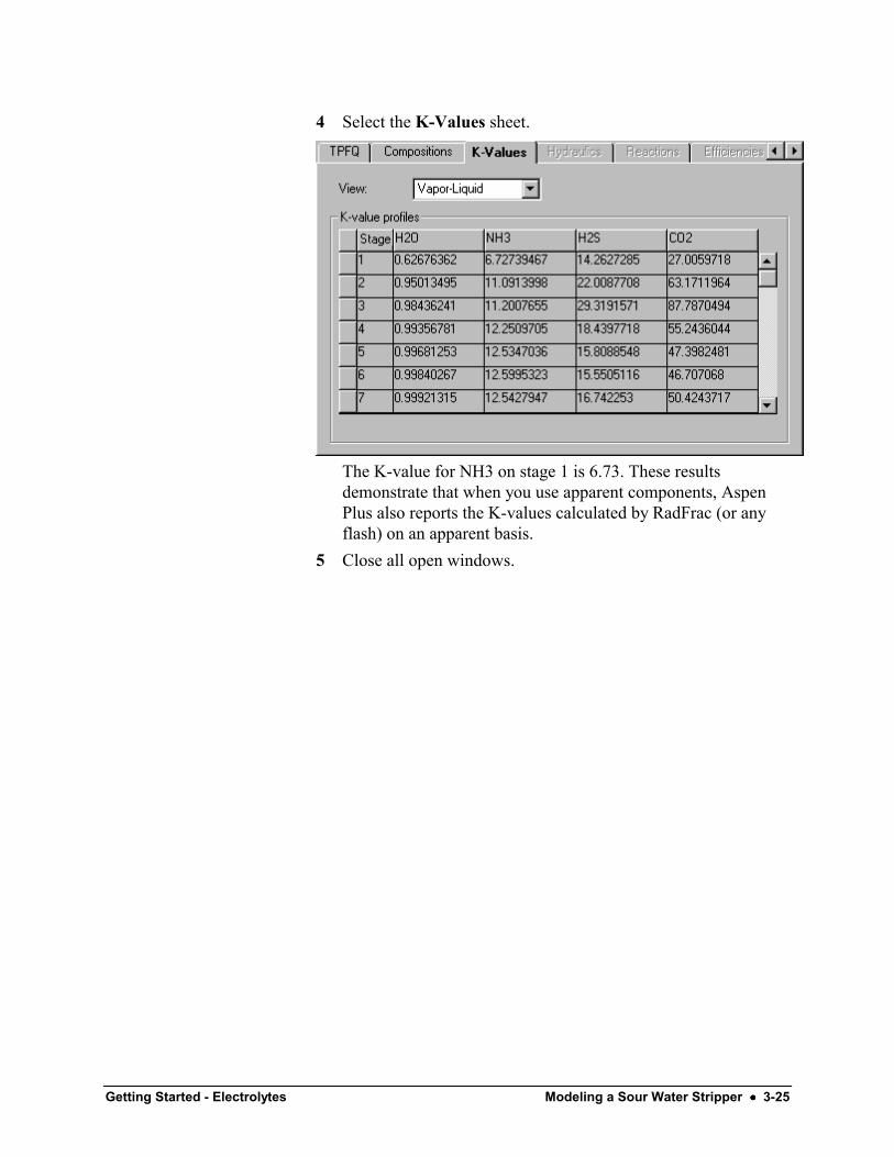
4 Select the K-Values sheet.
The K-value for NH3 on stage 1 is 6.73. These resultsdemonstrate that when you use apparent components, AspenPlus also reports the K-values calculated by RadFrac (or anyflash) on an apparent basis.
5 Close all open windows.
3-26 •••• Modeling a Sour Water Stripper Getting Started - Electrolytes
Converting to True ComponentsChoosing between the true component approach and the apparentcomponent is a matter of personal preference. For all simulations,the simulation results should be equivalent. To demonstrate this,you will convert this simulation from the apparent componentapproach to the true component approach.
To convert the simulation to the true component approach, youmust tell Aspen Plus to use the true component approach, and youmust adapt the Design Spec in the RadFrac block (5 ppm massapparent NH3 in the bottoms).1 From the Aspen Plus menu bar, select Data | Properties.2 On the Properties | Specifications | Global sheet, select the
checkbox next to Use true-components.
For the RadFrac block, you entered a desired specification of 5.0ppm (mass) of apparent NH3 in the bottoms. However, thisspecification is incorrect for the true component approach, becausea significant portion of the apparent NH3 is present as NH4+.1 On the flowsheet, select the RadFrac block.2 Right-click on the RadFrac block and select Input.3 From the Data Browser, select the Design Specs folder.
The Design Specs object manager appears.4 Select Design Spec ID 1, and click Edit.
The Design Specs | Specifications sheet appears. ModifyDesign Spec 1 to specify a stream property for the apparentmass fraction of NH3.
5 In the Type field, click and select Property value.6 In the Target field, enter 5.0E-6.7 In the Property set field, click the right mouse button and
select New.8 In the Aspen Plus dialog box, enter XNH3APP as the new
property set name.9 Click OK.10 Select the Feed/Product Streams sheet.11 In the Available streams column, select BOTTOMS and click
to move the stream to the Selected stream column.
To Tell Aspen Plus toUse the TrueComponentApproach
To Revise theRadFrac DesignSpecification to Applyto the ApparentComposition of NH3
Getting Started - Electrolytes Modeling a Sour Water Stripper •••• 3-27
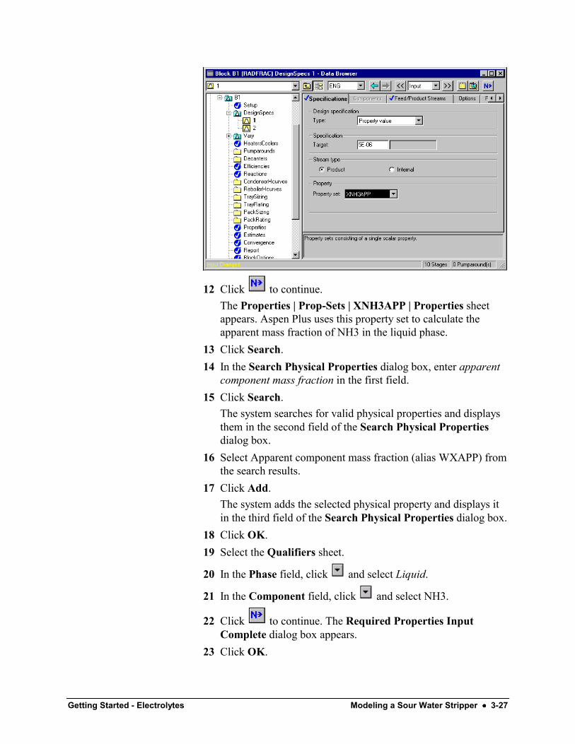
12 Click to continue.The Properties | Prop-Sets | XNH3APP | Properties sheetappears. Aspen Plus uses this property set to calculate theapparent mass fraction of NH3 in the liquid phase.
13 Click Search.14 In the Search Physical Properties dialog box, enter apparent
component mass fraction in the first field.15 Click Search.
The system searches for valid physical properties and displaysthem in the second field of the Search Physical Propertiesdialog box.
16 Select Apparent component mass fraction (alias WXAPP) fromthe search results.
17 Click Add.The system adds the selected physical property and displays itin the third field of the Search Physical Properties dialog box.
18 Click OK.19 Select the Qualifiers sheet.
20 In the Phase field, click and select Liquid.
21 In the Component field, click and select NH3.
22 Click to continue. The Required Properties InputComplete dialog box appears.
23 Click OK.
3-28 •••• Modeling a Sour Water Stripper Getting Started - Electrolytes
Running the True ComponentSimulationThe Required Input Complete dialog box appears informing youthat all specifications are complete and the simulation can be run.1 Click OK.
When the calculations finish, the message Results Availableappears in the status area at the right of the Main Windowtoolbar.
2 Close all open windows, and the Control Panel.
1 On the flowsheet, select the RadFrac block.2 Right-click inside the RadFrac block and select Results.3 From the Data Browser, select the Profiles folder.4 Select the Compositions sheet to view the results.
5 In the View field, click and select Liquid.This sheet reports the liquid phase mole fraction for allcomponents, including the ions. Stage 1 reports the followingcompositions:X NH3 = 0.02093X NH4+ = 0.01054
6 In the View field, click and select Vapor.Note that all ions have a mole fraction of zero in the vaporphase. Stage 1 reports the following composition:Y NH3 = 0.21115From these values, a stage 1 K-value for NH3 can becalculated.K = YNH3/XNH3 = 10.09
7 Select the K-Values sheet.On stage 1, the reported K value for NH3 matches the valueyou just calculated. This demonstrates that when truecomponents are used, the K-values calculated by RadFrac (orany flash) are also reported on a true basis.Note that the K-value calculated in the apparent simulation isnot equal to the K-value calculated in the true simulation due tothe partial dissociation of ammonia.The table below compares a number of the values calculated inthe true component simulation and the apparent componentsimulation.
To View SelectedResults of the TrueComponentSimulation
Getting Started - Electrolytes Modeling a Sour Water Stripper •••• 3-29
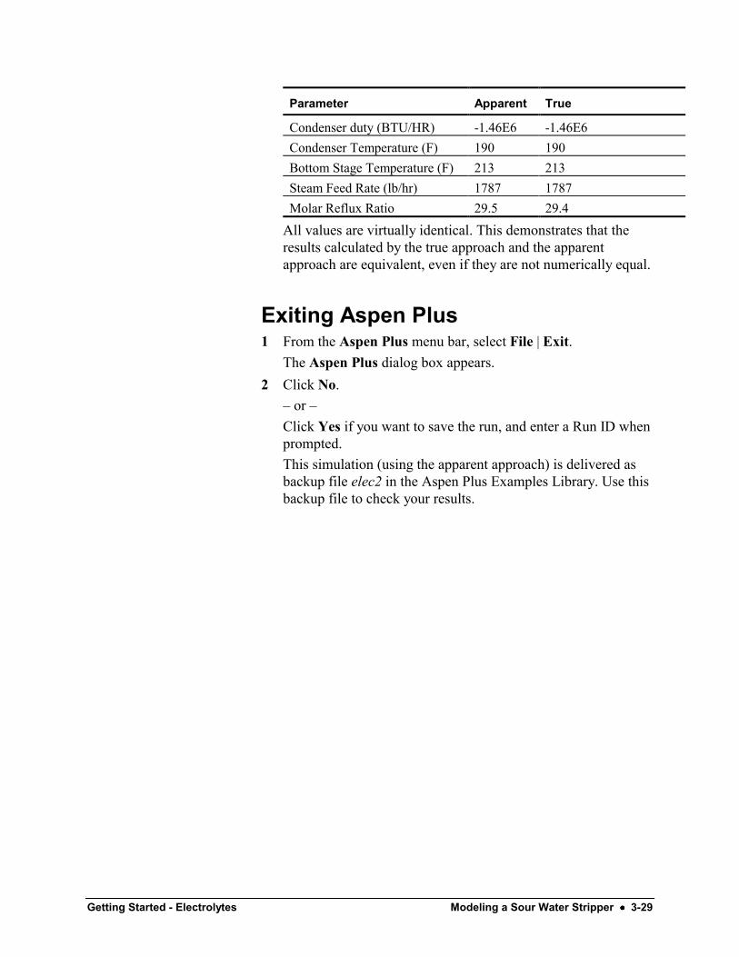
Parameter Apparent True
Condenser duty (BTU/HR) -1.46E6 -1.46E6Condenser Temperature (F) 190 190Bottom Stage Temperature (F) 213 213Steam Feed Rate (lb/hr) 1787 1787Molar Reflux Ratio 29.5 29.4
All values are virtually identical. This demonstrates that theresults calculated by the true approach and the apparentapproach are equivalent, even if they are not numerically equal.
Exiting Aspen Plus1 From the Aspen Plus menu bar, select File | Exit.
The Aspen Plus dialog box appears.2 Click No.
– or –Click Yes if you want to save the run, and enter a Run ID whenprompted.This simulation (using the apparent approach) is delivered asbackup file elec2 in the Aspen Plus Examples Library. Use thisbackup file to check your results.

3-30 •••• Modeling a Sour Water Stripper Getting Started - Electrolytes

Getting Started - Electrolytes Connecting to the Aspen Plus Simulation Engine •••• 4-1
Connecting to the Aspen PlusSimulation Engine
If either of the following conditions exist, you will be prompted tospecify the host computer for the Aspen Plus simulation engineafter you start the Aspen Plus User Interface:• The simulation engine is not installed on your PC.• The simulation engine is installed on your PC, but the
Activator security device is not connected to your PC.
In these cases, the Connect to Engine dialog box appears.
1 In the Server type field, click and select the type of hostcomputer for the simulation engine.
2 If you choose Local PC as the server for the simulation engine,you do not need to enter any more information into the dialogbox. Click OK to continue.If you choose Windows NT or 2000 server as the server for thesimulation engine, enter the following additional information:
3 In the Node name field, enter the node name of the computeron which the Aspen Plus simulation engine will execute.
4 In the other fields, enter the following information:User name Your user name for the specified
host/server.
Password Your password for the above user name.
Workingdirectory
The associated working directory.

4-2 •••• Connecting to the Aspen Plus Simulation Engine Getting Started - Electrolytes
5 Click OK.When the network connection is established, the messageConnection Established appears in the message box.If the Connection Established message does not appear, seeyour Aspen Plus system administrator for more information onnetwork protocols and host computers for the Aspen Plussimulation engine.


![Skaffold - storage.googleapis.com · [getting-started getting-started] Hello world! [getting-started getting-started] Hello world! [getting-started getting-started] Hello world! 5](https://img.dokumen.tips/doc/110x75/5ec939f2a76a033f091c5ac7/skaffold-getting-started-getting-started-hello-world-getting-started-getting-started.jpg)