Embed Size (px)
Citation preview

Trimble Survey Controller
Getting Started Guide
www.trimble.com
Trimble Engineering and Construction Division
5475 Kellenburger Road
Dayton, Ohio 45424
U.S.A.
800-538-7800 (Toll Free in U.S.A.)
+1-937-233-8921 Phone
+1-937-233-9004 Fax
www.trimble.com
™
www.trimble.com
TR
IM
3 m
m B
LE
ED
TR
IM
3 m
m B
LE
ED
TR
IM
3 m
m B
LE
ED
TRIM
3 mm BLEED
TR
IM
3 m
m B
LE
ED
TRIM
TRIM
TR
IM
3 m
m B
LE
ED
TR
IM
3 m
m B
LE
ED
TR
IM
3 m
m B
LE
ED
TRIM
TR
IM
3 m
m B
LE
ED
TRIM
3 mm BLEED
TRIM
3 mm BLEED
TRIM
3 mm BLEED
TRIM

Pathfndr.bk Page 2 Thursday, June 17, 1999 11:02 AM

Version 10.5Revision A
Part Number 571 702 061September 2002
Trimble Survey Controller™Getting Started Guide

Corporate OfficeTrimble Navigation LimitedEngineering and Construction Division5475 Kellenburger RoadDayton, Ohio 45424-1099U.S.A.Phone:(937) 233-8921(800) 538-7800Fax:(937) 233-9441www.trimble.comCopyright and Trademarks© 2002, Trimble Navigation Limited. All rights reserved. The Globe & Triangle logo, Trimble, Autolock, CMR, Trimble Survey Controller, TSCe, and Zephyr are trademarks of Trimble Navigation Limited. GPS Total Station is a trademark of Trimble Navigation Limited registered in the United States Patent and Trademark Office. The Bluetooth trademarks are owned by its proprietor and used by Trimble Navigation Limited under license. All other trademarks are the property of their respective owners.Release NoticeThis is the September 2002 release (Revision A) of the Trimble Survey Controller Getting Started Guide, part number 571 702 061. It applies to version 10.5 of the Trimble Survey Controller software.The following limited warranties give you specific legal rights. You may have others, which vary from state/jurisdiction to state/jurisdiction.Software and Firmware License, Limited WarrantyThis Trimble software and/or firmware product (the “Software”) is licensed and not sold. Its use is governed by the provisions of the applicable End User License Agreement (“EULA”), if any, included with the Software. In the absence of a separate EULA included with the Software providing different limited warranty terms, exclusions, and limitations, the following terms and conditions shall apply. Trimble warrants that this Trimble Software product will substantially conform to Trimble’s applicable published specifications for the Software for a period of ninety (90) days, starting from the date of delivery.Warranty RemediesTrimble's sole liability and your exclusive remedy under the warranties set forth above shall be, at Trimble’s option, to repair or replace any Product or Software that fails to conform to such warranty (“Nonconforming Product”), or refund the purchase price paid by you for any such Nonconforming Product, upon your return of any Nonconforming Product to Trimble in accordance with Trimble’s standard return material authorization procedures. Warranty Exclusions and DisclaimerThese warranties shall be applied only in the event and to the extent that: (i) the Products and Software are properly and correctly installed, configured, interfaced, maintained, stored, and operated in accordance with Trimble’s relevant operator's manual and specifications,
and; (ii) the Products and Software are not modified or misused. The preceding warranties shall not apply to, and Trimble shall not be responsible for defects or performance problems resulting from (i) the combination or utilization of the Product or Software with products, information, data, systems or devices not made, supplied or specified by Trimble; (ii) the operation of the Product or Software under any specification other than, or in addition to, Trimble's standard specifications for its products; (iii) the unauthorized modification or use of the Product or Software; (iv) damage caused by accident, lightning or other electrical discharge, fresh or salt water immersion or spray; or (v) normal wear and tear on consumable parts (e.g., batteries).THE WARRANTIES ABOVE STATE TRIMBLE'S ENTIRE LIABILITY, AND YOUR EXCLUSIVE REMEDIES, RELATING TO PERFORMANCE OF THE PRODUCTS AND SOFTWARE. EXCEPT AS OTHERWISE EXPRESSLY PROVIDED HEREIN, THE PRODUCTS, SOFTWARE, AND ACCOMPANYING DOCUMENTATION AND MATERIALS ARE PROVIDED “AS-IS” AND WITHOUT EXPRESS OR IMPLIED WARRANTY OF ANY KIND BY EITHER TRIMBLE NAVIGATION LIMITED OR ANYONE WHO HAS BEEN INVOLVED IN ITS CREATION, PRODUCTION, INSTALLATION, OR DISTRIBUTION, INCLUDING, BUT NOT LIMITED TO, THE IMPLIED WARRANTIES OF MERCHANTABILITY AND FITNESS FOR A PARTICULAR PURPOSE, TITLE, AND NONINFRINGEMENT. THE STATED EXPRESS WARRANTIES ARE IN LIEU OF ALL OBLIGATIONS OR LIABILITIES ON THE PART OF TRIMBLE ARISING OUT OF, OR IN CONNECTION WITH, ANY PRODUCTS OR SOFTWARE. SOME STATES AND JURISDICTIONS DO NOT ALLOW LIMITATIONS ON DURATION OR THE EXCLUSION OF AN IMPLIED WARRANTY, SO THE ABOVE LIMITATION MAY NOT APPLY TO YOU.TRIMBLE NAVIGATION LIMITED IS NOT RESPONSIBLE FOR THE OPERATION OR FAILURE OF OPERATION OF GPS SATELLITES OR THE AVAILABILITY OF GPS SATELLITE SIGNALS.Limitation of LiabilityTRIMBLE’S ENTIRE LIABILITY UNDER ANY PROVISION HEREIN SHALL BE LIMITED TO THE GREATER OF THE AMOUNT PAID BY YOU FOR THE PRODUCT OR SOFTWARE LICENSE OR U.S.$25.00. TO THE MAXIMUM EXTENT PERMITTED BY APPLICABLE LAW, IN NO EVENT SHALL TRIMBLE OR ITS SUPPLIERS BE LIABLE FOR ANY INDIRECT, SPECIAL, INCIDENTAL, OR CONSEQUENTIAL DAMAGES WHATSOEVER UNDER ANY CIRCUMSTANCE OR LEGAL THEORY RELATING IN ANY WAY TO THE PRODUCTS, SOFTWARE, AND ACCOMPANYING DOCUMENTATION AND MATERIALS, (INCLUDING, WITHOUT LIMITATION, DAMAGES FOR LOSS OF BUSINESS PROFITS, BUSINESS INTERRUPTION, LOSS OF BUSINESS INFORMATION, OR ANY OTHER PECUNIARY LOSS), REGARDLESS OF WHETHER TRIMBLE HAS BEEN ADVISED OF THE POSSIBILITY OF ANY SUCH LOSS AND REGARDLESS OF THE COURSE OF DEALING WHICH DEVELOPS OR HAS DEVELOPED BETWEEN YOU AND TRIMBLE. BECAUSE SOME STATES AND JURISDICTIONS DO NOT ALLOW THE EXCLUSION OR LIMITATION OF LIABILITY FOR CONSEQUENTIAL OR INCIDENTAL DAMAGES, THE ABOVE LIMITATION MAY NOT APPLY TO YOU.

ContentsIntroductionWhat’s in the box? . . . . . . . . . . . . . . . . . . . . . . . . vii
1 The ACU ControllerAttaching the ACU . . . . . . . . . . . . . . . . . . . . . . . . . 2ACU Function Keys . . . . . . . . . . . . . . . . . . . . . . . . 3Power Supply . . . . . . . . . . . . . . . . . . . . . . . . . . . . 6Screen. . . . . . . . . . . . . . . . . . . . . . . . . . . . . . . . 7Backlight . . . . . . . . . . . . . . . . . . . . . . . . . . . . . . 8Clock . . . . . . . . . . . . . . . . . . . . . . . . . . . . . . . . 9Storage Card . . . . . . . . . . . . . . . . . . . . . . . . . . . . 9Rebooting. . . . . . . . . . . . . . . . . . . . . . . . . . . . . . 9Caring for the unit . . . . . . . . . . . . . . . . . . . . . . . . 10
2 Conventional SurveyPreparing for the Survey . . . . . . . . . . . . . . . . . . . . . 13Creating a New Job. . . . . . . . . . . . . . . . . . . . . . . . 15Starting a Survey . . . . . . . . . . . . . . . . . . . . . . . . . 16Trimble 3600 and 5600 Configuration . . . . . . . . . . . . . . 17GDM CU Programs . . . . . . . . . . . . . . . . . . . . . . . 18Zeiss Elta Programs . . . . . . . . . . . . . . . . . . . . . . . 23GDM CU and Zeiss Measurement Modes . . . . . . . . . . . . 27
3 GPS SurveySetting Up a GPS Total Station 5700 Receiver (Base) . . . . . . 29Setting Up a GPS Total Station 5800 Receiver (Rover) . . . . . 31
4 Data TransferUsing the Data Transfer Utility. . . . . . . . . . . . . . . . . . 33
A Menu Structure

Table of Contents

IntroductionWelcome to the Trimble Survey Controller Getting Started Guide.Information in this manual includes:
• The Trimble™ ACU controller
• Starting conventional surveys
• Starting GPS surveys
• Transferring data to the office PCThe Trimble Survey Controller™ software configures and controls receivers and instruments used in GPS and conventional surveys.
Note – If you are not familiar with GPS, visit Trimble’s website (www.trimble.com) for an interactive look at Trimble and GPS.
Related information
Sources of related information include the following:
• Help – the software has built-in, context-sensitive help that lets you quickly find the information you need. The Help is also available on the CD.
• Release notes – the release notes describe new features of the product, information not included in the manuals, and any changes to the manuals.
Technical assistance
If you have a problem and cannot find the information you need in the product documentation, contact your local distributor.
Trimble Survey Controller is also available on the TSCe™ controller. The information in this document also applies to the TSCe. Where details apply only to the TSCe, they are indicated with this TSCe icon.

Introduction
Your comments
Your feedback about the supporting documentation helps us to improve it with each revision. To forward your comments, send an e-mail to [email protected]
vi Trimble Survey Controller Getting Started Guide
Introduction
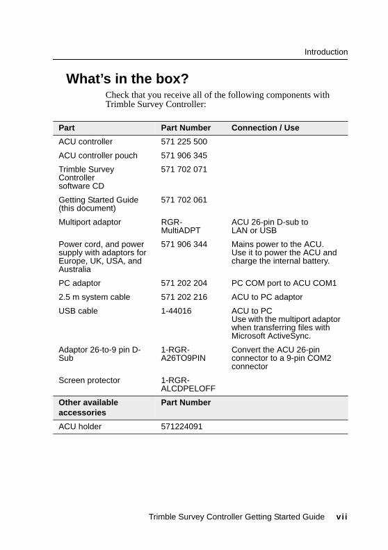
0.1 What’s in the box?Check that you receive all of the following components with Trimble Survey Controller:
Part Part Number Connection / Use
ACU controller 571 225 500
ACU controller pouch 571 906 345
Trimble Survey Controller software CD
571 702 071
Getting Started Guide (this document)
571 702 061
Multiport adaptor RGR-MultiADPT
ACU 26-pin D-sub to LAN or USB
Power cord, and power supply with adaptors for Europe, UK, USA, and Australia
571 906 344 Mains power to the ACU.Use it to power the ACU and charge the internal battery.
PC adaptor 571 202 204 PC COM port to ACU COM1
2.5 m system cable 571 202 216 ACU to PC adaptor
USB cable 1-44016 ACU to PCUse with the multiport adaptor when transferring files with Microsoft ActiveSync.
Adaptor 26-to-9 pin D-Sub
1-RGR-A26TO9PIN
Convert the ACU 26-pin connector to a 9-pin COM2 connector
Screen protector 1-RGR-ALCDPELOFF
Other available accessories
Part Number
ACU holder 571224091
Trimble Survey Controller Getting Started Guide vii

Introduction
vii i Trimble Survey Controller Getting Started Guide

C H A P T E R
1The ACU Controller 1
In this chapter:
■ Attaching the ACU
■ ACU function keys
■ Power supply
■ Screen
■ Clock
■ Storage card
■ Rebooting
■ Caring for the unit
Trimble Survey Controller is designed to run on the ACU controller. This chapter describes the controller and how to use it. Figure 1.1 shows the front of the ACU and its keys.
Figure 1.1 The ACU controller – front view

The ACU Controller
1.1 Attaching the ACU
C Warning – Switch off the ACU when attaching it to the holder or when changing the batteries in the holder with the ACU attached. Otherwise, the on/off status of the ACU and the holder may become unsyncronised.
To attach the ACU:
1. Hold the controller with both hands.
2. Fit the groove on the back of the controller over the lower lip on the front of the holder.
3. Press down and rest the back of the controller flat against the holder.
4. Gently release downward pressure and guide the controller so that the teeth on the front of the holder click into the notches on top of the controller.
Figure 1.2 shows how to attach the ACU to the holder.
Figure 1.2 Attaching the ACU
2 Trimble Survey Controller Getting Started Guide

The ACU Controller
1.2 ACU Function KeysTable 1.1 describes Trimble Survey Controller functions that are associated with the ACU icons.
Table 1.1 ACU function keys
On this instrument or receiver ... tap ... to ...
Conventional or GPS
access the main Trimble Survey Controller menu
Conventional (with Autolock™)
access the Trimble function screen
switch Autolock on and start a search
switch Autolock on or off
take a measurement
Trimble Survey Controller Getting Started Guide 3

The ACU Controller
Conventional (with servos)
turn the instrument horizontally to the current point name or stakeout location
turn the instrument vertically to the current point name or stakeout location
turn the instrument horizontally and vertically to the current point name or stakeout location
change face
take a measurement
Conventional (3600)
activate the first softkey (F1)
activate the second softkey (F2)
activate the third softkey (F3)
activate the fourth softkey (F4)
take a measurement
Table 1.1 ACU function keys (Continued)
On this instrument or receiver ... tap ... to ...
4 Trimble Survey Controller Getting Started Guide

The ACU Controller
GPS
access the Position dialog
access the Satellites dialog
activate the first softkey (F1)
activate the second softkey (F2)
activate the third softkey (F3)
activate the fourth softkey (F4)
activate the Enter button
Table 1.1 ACU function keys (Continued)
On this instrument or receiver ... tap ... to ...
Trimble Survey Controller Getting Started Guide 5

The ACU Controller
1.3 Power SupplyUnder normal operation, the ACU draws power from the device it is attached to or from one of the following external batteries:
• 12V NiMH
• 7.4 Lithium-ionThe ACU has an internal, rechargeable 4.8 volt 600 mAh NimH battery. If power is lost during operation the ACU automatically switches over to this battery, which provides approximately two hours running time when fully charged. The ACU holder has dual 7.4V 1.8Ah lithium-ion batteries. When fully charged, these provide approximately 15 hours running time to the ACU through the 7-pin backplane.
1.3.1 Charging the batteriesThe internal battery of the ACU is automatically charged when the controller is connected to an external power supply.To charge the internal battery:
• Connect the AC adaptor from the ACU 4-pin Hirose port to the mains power supply.
The ACU detects the following low power levels from the external batteries:
• 10 volts (12V NiMH battery)
• 6 volts (Lithium-ion battery)The ACU alerts you when power level is critically low. If this happens, turn the equipment off and change the external battery. Otherwise, the ACU will switch over to its internal battery.
The TSCe is supplied with a rechargeable 4.8 volt 3800 mAh NiMH battery, which provides over 30 hours of running time when fully charged.
6 Trimble Survey Controller Getting Started Guide

The ACU Controller
1.3.2 Battery replacement
C Warning – Do not attempt to change the battery or you may seriously damage the ACU. Contact your local distributor.
1.4 ScreenThe ACU reflective LCD screen can be viewed easily in direct sunlight or in overcast conditions. It also incorporates a passive touch interface for navigation. Tap elements on the display screen with a stylus or your finger.
The TSCe incorporates a quick circuit that recharges its internal NiMH battery to 90% capacity in approximately one hour. To charge the battery, use one of the following methods:– Connect the AC adaptor to a mains power supply, with the Multiport adaptor (part number RGR-MULTIADPT) plugged into the 26-pin port (COM 2) on the TSCe. – Connect the O-shell to O-shell lemo (PN 31288-02) to Port 1 on the receiver (running on mains power)– Connect the O-shell lemo from the OSMII to the O-shell lemo on the TSCe.The control unit monitors the battery while it is charging. To turn off the display, press the _ key.Before using the TSCe on battery power alone, charge the battery for a minimum of two hours.
Contact your local distributor for a replacement battery.
Trimble Survey Controller Getting Started Guide 7

The ACU Controller
1.4.1 Recalibrating the touch screenIf the touch screen does not respond properly when you tap it, recalibrate it as follows:
1. Tap and select Settings / Control Panel / Stylus. The Stylus Properties dialog appears.
2. In the Calibration tab, tap [Recalibrate].
3. Follow the prompts.
1.4.2 Disabling the touch screenTo clean the ACU screen during a survey, press [Ctrl]+ (the alpha key) then [1] four times (to access “S”) to disable it. This locks the screen and keypad, except for the [Esc] key.
To enable the touch screen and keypad again, press [Esc].
1.5 BacklightTo modify the backlight settings:
• Select Display / Backlight from the Control Panel.
• If the Auto on option is disabled, press ~ and .Press ~ and to switch between these backlight modes:
• screen and keyboard on
• screen only on
• screen and keyboard off
To disable the TSCe screen, press [Ctrl]+[S].
8 Trimble Survey Controller Getting Started Guide

The ACU Controller
1.6 ClockTo change time and date settings on the ACU:
1. Tap and select Settings / Control Panel / Date/Time.
The Date/Time Properties dialog appears.
2. Change the date and time as required. Press = to accept the new settings or E to cancel.
Note – When you connect the ACU to a GPS receiver or to your PC using Microsoft ActiveSync, the date and time are automatically updated.
1.7 Storage CardThe ACU has a built-in storage card for your data and programs. This appears in the Windows CE files system as the \Disk folder.
Note – The system maintains several special files on the card, such as nk.bin and ranger.reg, which contain information crucial to the correct operation of the ACU. Directly modifying these files may result in the ACU failing to operate correctly.
1.7.1 Safeguarding dataBack up your work regularly using Microsoft ActiveSync or the Trimble Data Transfer utility. For more information, see Chapter 4, Data Transfer.
1.8 RebootingIf the ACU fails to respond to keystrokes, then perform one of the following resets, which shut down the hardware and restart the Trimble Survey Controller software.
1.8.1 Soft reset (warm boot) This method retains all data.
Trimble Survey Controller Getting Started Guide 9

The ACU Controller
To perform a soft reset:
• Hold down ~ and C, while you press and release .The ACU resets to the default Microsoft Windows desktop view.
1.8.2 Hard reset (cold boot)This method retains any data on the built-in storage card (the \Disk folder). However, a hard reset clears the contents of the RAM memory, including any desktop shortcuts that you have created.To perform a hard reset:
1. Hold down _.
After approximately 5 seconds, a countdown timer appears, indicating that the controller will reset.
2. Continue to hold _ for a further 5 seconds, then release.The controller briefly displays the boot screen and then resets to the default Microsoft Windows desktop view.
1.9 Caring for the unitTrimble recommends the following to maintain your ACU during everyday use, and to prevent potential physical damage or data loss.Operating temperature: –20° C to +55° CStorage temperature: –30° C to +70° C
To warm boot the TSCe, hold down ~ and C, while you press and release _.
Do not expose the TSCe to temperatures below –20° C (–4° F) or above +60° C (140° F). Do not leave it in direct sunlight for extended periods of time.
10 Trimble Survey Controller Getting Started Guide

The ACU Controller
Shock
Environment – The ACU is designed to withstand driving rain and dust.
Cleaning the case – Clean the controller with a soft cloth dampened with clean water or with water containing a mild detergent. If the keyboard has dirt or grime on it, use compressed air or a vacuum cleaner, or gently rinse it with clean water.Care of the touch screen – Clean the touch screen with a soft cloth dampened with clean water or glass cleaner. Do not apply any cleaner directly to the screen. Apply the cleaner to the soft cloth and then gently wipe the screen.
Note – Do not use abrasive cleaners.Applying a screen protector – Use a screen protector to help keep the touch screen clean and protected. Clean the screen thoroughly and leave it slightly wet. Peel the backing from the screen protector and then apply the protector to the screen. Use a soft cloth to squeeze the excess water and air from under the screen protector.
The TSCe is designed to withstand a MIL-STD-810E drop. However, impact or pressure on the display screen may cause it to crack. Protect the display from impact, pressure, or abrasive substances.
The TSCe is designed to be immersible in up to one meter of water, for up to one hour.
Trimble Survey Controller Getting Started Guide 11

The ACU Controller
12 Trimble Survey Controller Getting Started Guide

C H A P T E R
2Conventional Survey 2
In this chapter:
■ Preparing for the survey
■ Creating a new job
■ Starting a survey
■ Trimble 3600 and 5600 configuration
■ GDM CU programs
■ Zeiss Elta programs
■ GDM CU and Zeiss measurement modes
This chapter describes how to carry out a conventional survey with Trimble Survey Controller when the ACU is attached to a Trimble 3600 or 5600 instrument. For more information, refer to the Help.
2.1 Preparing for the SurveyTo do this:
1. Set up the instrument.
2. Ensure that the ACU is turned off, and then attach it to the instrument. For more information, see page 2.
3. Press _ on the ACU to switch on the instrument.
4. Start Trimble Survey Controller. The software automatically connects to the instrument and the Electronic level dialog appears.
Note – If you have a Trimble 3600 instrument with a laser plummet, the laser plummet automatically turns on when this dialog appears.
5. Position and level the instrument and tap C. If you are using a Trimble 5600 instrument, the compensator is automatically initialized now.

Conventional Survey
6. When prompted by the Corrections dialog, enter appropriate atmospheric values and tap C.
7. The Survey Controller Basic dialog appears. It displays the current instrument readings.
Note – You cannot store measurements in this mode.
8. Tap E to exit Survey Controller Basic mode. The main Trimble Survey Controller menu appears, and you can then begin a survey.
If you are running a robotic survey, see the following section. Otherwise go directly to Creating a New Job, page 15.
2.1.1Using the ACU to prepare for a robotic survey To survey using a 5600 robotic instrument:
1. From the main menu, select Instrument / Radio. Set the radio channel, station address and remote address and tap C.
2. From the main menu, select Survey / Start Robotic to prepare the 5600 for robotic connection.
3. Tap w to suspend the 5600 and the ACU ready for robotic operation.
4. Remove the ACU from the 5600.
Note – If the radio settings on the 5600 instrument are already set to match the ACU, and the instrument is level, press the trigger button on the back of the 5600 to turn on the instrument for a robotic connection.
5. Ensure that the ACU is turned off, and then attach it to the ACU holder. For more information, see page 2.
6. Connect the ACU to Port A on the remote radio using the ACU holder or a 0.4m, 4 pin Hirose cable.
7. Turn on the active target or connect it to Port B on the remote radio.
Once the ACU is attached to the holder, Trimble Survey Controller connects to the remote radio and then to the 5600. The 5600 is re-initialized to compensate for the earlier removal of the controller.
You can now create a job, see page 15, and start the survey, see page 16.
14 Trimble Survey Controller Getting Started Guide
Conventional Survey
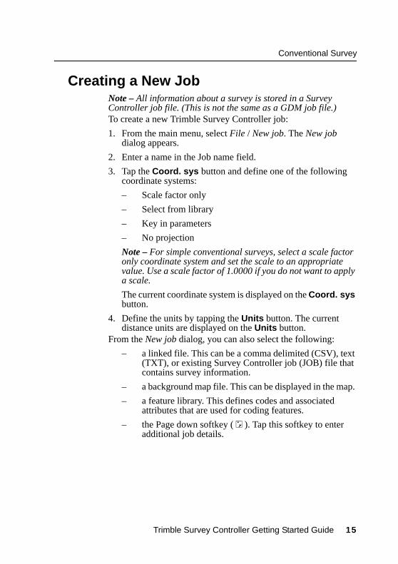
2.2 Creating a New JobNote – All information about a survey is stored in a Survey Controller job file. (This is not the same as a GDM job file.)To create a new Trimble Survey Controller job:
1. From the main menu, select File / New job. The New job dialog appears.
2. Enter a name in the Job name field.
3. Tap the Coord. sys button and define one of the following coordinate systems:
– Scale factor only
– Select from library
– Key in parameters
– No projection
Note – For simple conventional surveys, select a scale factor only coordinate system and set the scale to an appropriate value. Use a scale factor of 1.0000 if you do not want to apply a scale.
The current coordinate system is displayed on the Coord. sys button.
4. Define the units by tapping the Units button. The current distance units are displayed on the Units button.
From the New job dialog, you can also select the following:
– a linked file. This can be a comma delimited (CSV), text (TXT), or existing Survey Controller job (JOB) file that contains survey information.
– a background map file. This can be displayed in the map.
– a feature library. This defines codes and associated attributes that are used for coding features.
– the Page down softkey ( D ). Tap this softkey to enter additional job details.
Trimble Survey Controller Getting Started Guide 15

Conventional Survey
2.3 Starting a SurveyTo start a survey, select Survey from the main menu, and then select one of the following:
• Station setup – to orientate the survey on a point with known coordinates. Multiple backsight points can be added to define the orientation as required.
• Resection – to orientate the survey on a point with unknown coordinates. The resection will calculate the coordinates for the instrument point and orientate the survey.
Once the station setup or resection is completed, select one of the following:
• Survey / Measure points – to perform survey measurements.
• Survey / Stakeout – to stake points, lines, arcs, roads or DTMs.
• Map – to graphically review the survey data or to perform survey operations.
• Favorites / Review – to view the data stored in the Survey Controller job.
For more information, see GDM CU Programs, page 18, or Zeiss Elta Programs, page 23.
16 Trimble Survey Controller Getting Started Guide

Conventional Survey
2.4 Trimble 3600 and 5600 ConfigurationTo view and modify the instrument configuration, select Instrument from the Trimble Survey Controller main menu. The instrument menu appears with all available options for the current instrument, as shown below:
2.4.1Modifying instrument configurationTo quickly access and modify the instrument configuration:1. Select the Trimble function key ( ) on the ACU, or the
instrument icon on the status bar (for example, ). The Trimble function screen appears.
2. Select the required icon to change the instrument configuration.
2.4.2Changing the target for DR measurementsFor 3600 and 5600 instruments with Direct Reflex (DR), tap the target icon on the status bar and select one of the following:
• DR target – to change the target height and prism constant and enable the DR EDM mode on the instrument.
• Normal target – to change to a normal target height and prism constant and disable the DR EDM mode.
Instrument
Item 3600 5600
Electronic level
Direct Reflex (DR instrument only)
Instrument controls (Servo only) x
Tracklight
Autolock (Autolock only) x
Instrument settings
Radio settings (Robotic only) x
Adjust instrument
Survey Controller basic
Trimble Survey Controller Getting Started Guide 17

Conventional Survey
2.5 GDM CU ProgramsTrimble Survey Controller offers similar functionality to the GDM Control Unit. To access GDM CU programs, use the Trimble function key as you would the PRG key on the GDM CU.Table 2.1 shows where to find specific GDM CU programs within Trimble Survey Controller.
Table 2.1 GDM CU programs in Trimble Survey Controller
Trimble Survey Controller
GDM CU program Select ... to ...
Shortcut
( + number)
20 - Station setup
Survey / Station setup
perform a known station or known station + station setup.
20
Survey / Resection perform a free station or eccentric station setup.
21 - Z/IZ
Survey / Resection and set the calculate option to V (1D)
calculate an instrument elevation 21
22 - Angle measurement
Survey / Measure rounds
measure a defined number of Face 1 (CI) and Face 2 (CII) measurements. 22
Survey / Measure points
measure individual Face 1 and/or Face 2 measurements.
23 - Set Out Survey / Stakeout / Points
set out points with known coordinates. Points can be defined via Keyin / Points or obtained from a linked CSV, TXT or Survey Controller JOB file.
23
18 Trimble Survey Controller Getting Started Guide

Conventional Survey
24 - Refline Survey / Station and offset
measure or set out relative to a line, arc, or road. The line, arc, or road can be defined via Keyin / Line, Arc, Road, or imported to the Survey Controller job. Refline / Unknown line is not supported.
24
25 - Area Calculation
COGO / Compute area
calculate an area. 25
26 - Distob COGO / Compute inverse
calculate an inverse between two points. 26
27 - Moving Coordinates Forward
Trimble Survey Controller stores raw data and automatically calculates point coordinates. There is no specific program required in Trimble Survey Controller to move coordinates forward. Instead use Measure Points.
27
28 - Obstructed Point
Survey / Measure points and set the method to Dual-prism offset. 28
29 - Roadline Survey / Stakeout / Roads
measure or set out relative to a road. Roads can be defined using horizontal alignments, vertical alignments, and templates defining cross sections.
29
Table 2.1 GDM CU programs in Trimble Survey Controller (Continued)
Trimble Survey Controller
GDM CU program Select ... to ...
Shortcut
( + number)
Trimble Survey Controller Getting Started Guide 19

Conventional Survey
30 - Measure Coordinates
Trimble Survey Controller stores raw data and automatically calculates point coordinates. There is no specific program required in Trimble Survey Controller to measure coordinates. Instead, use Measure Points.Points can be exported to a CSV or TXT file, via Files / Import/Export / Send ASCII data, for use as a control file. To access the control file from another job, select the CSV, TXT or JOB file as a linked file via Files / Properties of current job.
30
32 - Angle measurement plus
Survey / Measure rounds
measure a defined number of Face 1 (CI) and Face 2 (CII) measurements.
32
Survey / Measure rounds / Options
configure the number of rounds to be measured; select automatic measurements (to Remote Targets only); set the observation order; measure distances on Face 2(CII); define a time interval between rounds (automatic measurements only).
33 - Robotic Lite Not supported
Table 2.1 GDM CU programs in Trimble Survey Controller (Continued)
Trimble Survey Controller
GDM CU program Select ... to ...
Shortcut
( + number)
20 Trimble Survey Controller Getting Started Guide
Conventional Survey
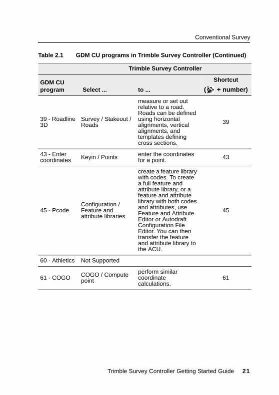
39 - Roadline 3D
Survey / Stakeout / Roads
measure or set out relative to a road. Roads can be defined using horizontal alignments, vertical alignments, and templates defining cross sections.
39
43 - Enter coordinates Keyin / Points enter the coordinates
for a point. 43
45 - PcodeConfiguration / Feature and attribute libraries
create a feature library with codes. To create a full feature and attribute library, or a feature and attribute library with both codes and attributes, use Feature and Attribute Editor or Autodraft Configuration File Editor. You can then transfer the feature and attribute library to the ACU.
45
60 - Athletics Not Supported
61 - COGO COGO / Compute point
perform similar coordinate calculations.
61
Table 2.1 GDM CU programs in Trimble Survey Controller (Continued)
Trimble Survey Controller
GDM CU program Select ... to ...
Shortcut
( + number)
Trimble Survey Controller Getting Started Guide 21

Conventional Survey
65 - Direct Reflex
COGO / Compute point
perform a From a baseline (Corner + distance), Brng-Line intersect (Corner + angle), or Four point intersection (Two lines intersection) measurement. 65
Survey / Measure points
perform a Circular Object (Eccentric object) measurement. Surface scan is not supported.
66 - Monitoring
Survey / Measure rounds
configure the number of rounds to be measured, automatically store points (to Remote Targets only), and define a time interval between rounds.
66Survey / Measure rounds / Options
Menu 2 (View/Edit)
Files / Review current job review and edit the data stored in the job.
Favorites / Review
F 6 (Change target height)
the target icon on the status bar quickly edit the target details.F 33 (Change
prism constant)
GDM Job Files export
Trimble Data Transfer (connected to Trimble Survey Controller)
transfer the GDM Job file. For more information about transferring data, see Chapter 4, Data Transfer.
Table 2.1 GDM CU programs in Trimble Survey Controller (Continued)
Trimble Survey Controller
GDM CU program Select ... to ...
Shortcut
( + number)
22 Trimble Survey Controller Getting Started Guide
Conventional Survey
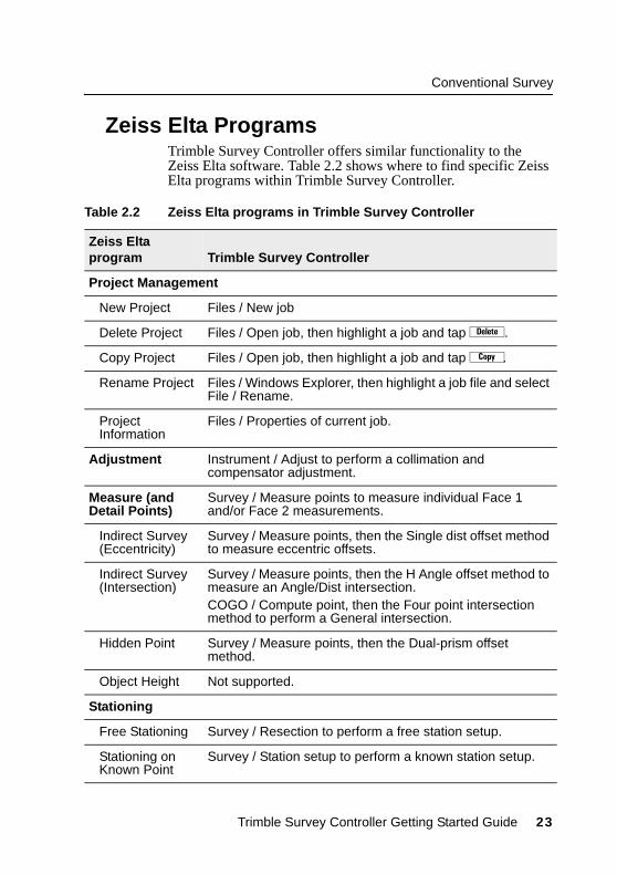
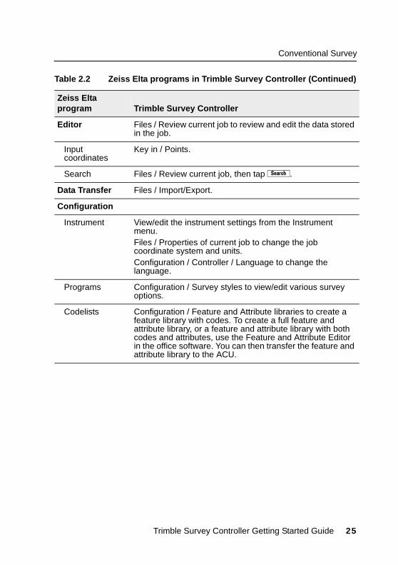
2.6 Zeiss Elta ProgramsTrimble Survey Controller offers similar functionality to the Zeiss Elta software. Table 2.2 shows where to find specific Zeiss Elta programs within Trimble Survey Controller.
Table 2.2 Zeiss Elta programs in Trimble Survey Controller
Zeiss Elta program Trimble Survey Controller
Project Management
New Project Files / New job
Delete Project Files / Open job, then highlight a job and tap d.
Copy Project Files / Open job, then highlight a job and tap Y.
Rename Project Files / Windows Explorer, then highlight a job file and select File / Rename.
Project Information
Files / Properties of current job.
Adjustment Instrument / Adjust to perform a collimation and compensator adjustment.
Measure (and Detail Points)
Survey / Measure points to measure individual Face 1 and/or Face 2 measurements.
Indirect Survey (Eccentricity)
Survey / Measure points, then the Single dist offset method to measure eccentric offsets.
Indirect Survey (Intersection)
Survey / Measure points, then the H Angle offset method to measure an Angle/Dist intersection. COGO / Compute point, then the Four point intersection method to perform a General intersection.
Hidden Point Survey / Measure points, then the Dual-prism offset method.
Object Height Not supported.
Stationing
Free Stationing Survey / Resection to perform a free station setup.
Stationing on Known Point
Survey / Station setup to perform a known station setup.
Trimble Survey Controller Getting Started Guide 23

Conventional Survey
Eccentric Stationing
Survey / Resection to perform an eccentric station setup.
Heightstationing Survey / Resection and then the V (1D) calculate option.
Coordinates
Detail Points (Verification Points)
Trimble Survey Controller checks all points using the duplicate point tolerances specified in the survey style.
Setting Out Survey / Stakeout / Points to setout points with known coordinates. Points can be defined via Keyin / Points or from an existing CSV, TXT or Survey Controller JOB file.
Traverse COGO / Traverse to adjust a traverse. Any station setup point can be used as a traverse point.
Intersect LinesCOGO / Compute point and use an appropriate method.
Intersect Arcs
Transformation Not Supported.
Roadline Lite Survey / Stakeout / Roads to measure or set out relative to a road. Roads can be defined using horizontal alignments, vertical alignments and templates defining cross sections.
Special
Multiple Rounds Survey / Measure Rounds to measure a defined number of Face 1 and Face 2 measurements.
Point to Line Survey / Station and Offset to measure or set out relative to a line, arc or road. The line, arc, or road can be defined via Keyin / Line, Arc, Road or imported to the Survey Controller job.
3D Plane Not supported.
Area Computation
COGO / Compute Area to calculate between points.
Connecting Distances
COGO / Inverse to calculate an angle and distance between two points.
Table 2.2 Zeiss Elta programs in Trimble Survey Controller (Continued)
Zeiss Elta program Trimble Survey Controller
24 Trimble Survey Controller Getting Started Guide
Conventional Survey
Editor Files / Review current job to review and edit the data stored in the job.
Input coordinates
Key in / Points.
Search Files / Review current job, then tap æ.
Data Transfer Files / Import/Export.
Configuration
Instrument View/edit the instrument settings from the Instrument menu. Files / Properties of current job to change the job coordinate system and units.Configuration / Controller / Language to change the language.
Programs Configuration / Survey styles to view/edit various survey options.
Codelists Configuration / Feature and Attribute libraries to create a feature library with codes. To create a full feature and attribute library, or a feature and attribute library with both codes and attributes, use the Feature and Attribute Editor in the office software. You can then transfer the feature and attribute library to the ACU.
Table 2.2 Zeiss Elta programs in Trimble Survey Controller (Continued)
Zeiss Elta program Trimble Survey Controller
Trimble Survey Controller Getting Started Guide 25

Conventional Survey
Additional functions
Input of Parameters
Tap the target icon on the status bar to edit the target height and prism constant.Select Options from the Station Setup, Resection, Measure Points, or Measure Rounds dialog to edit the temperature, pressure and ppm.
Recording mode (R-M, R-C, R-MC)
Trimble Survey Controller stores raw data and automatically calculates point coordinates. There is no specific program required in Trimble Survey Controller to measure coordinates. To export points to a CSV or TXT file (to use as a control file), select Files / Import/Export / Send ASCII data. To link a control file to the current job, select Files / Properties of current job, then the required CSV, TXT, or JOB file.
Export M5 files Use Data Transfer (connected to Trimble Survey Controller) to transfer the M5 file to your PC. For more information, see Chapter 4, Data Transfer.
Table 2.2 Zeiss Elta programs in Trimble Survey Controller (Continued)
Zeiss Elta program Trimble Survey Controller
26 Trimble Survey Controller Getting Started Guide

Conventional Survey
2.7 GDM CU and Zeiss Measurement ModesGDM CU and Zeiss measurement modes are supported in Trimble Survey Controller. Select the Trimble function key or the instrument icon from the status bar to change measurement modes as follows:
2.7.1GDM CU D-barTo access this mode in Trimble Survey Controller, select the Averaged Observations measurement method from the Station setup, Resection, Measure points, or Measure Rounds menu.Then select one of the following:
• To measure a defined number of observations, select Options / Averaged observations. Standard deviations are updated and displayed during measurement.
• To continually measure until the standard deviations are acceptable, select Options and enter a high number in the Averaged Observations field.
Tap C when the standard deviations are acceptable.
2.7.2Matched Face 1 and Face 2 measurementsTrimble Survey Controller lets you make Face 1 (direct) and Face 2 (reverse) measurements at any time and in any order. The software averages a pair of observations in a matched pair record, then averages multiple matched pair records (rounds of observations) in a mean turned angle record.
Measurement mode FunctionStatus bar indicator
STD (Standard / normal)
Measures and averages angles as one standard distance is measured.
S
FSTD (Fast standard / rapid)
Measures and averages angles as one fast standard distance is measured.
F
TRK (Tracking) Continually measures angles and distances.
T
Trimble Survey Controller Getting Started Guide 27

Conventional Survey
To measure a point using both faces:
1. Complete a station setup.
2. Measure a point.
3. Measure the same point again on the opposite face of the instrument. In the Point name field, use the same name as in step 2.
When using a servo instrument:
• To automatically change face and retain the point name after completing the F1 measurement, select Survey / Options and then select the Auto matched pair (F1/F2) check box.
• To perform an F2 measurement the same as the F1 measurement, press the trigger button on the back of the instrument. Press and hold the button to change the instrument back to F1.
• If distances are not required on F2, clear the Measure distance on face 2 check box.
When using an instrument with Autolock and Remote Targets:
• Select Auto matched pair (F1/F2) to automatically change face, retain the point name and start the F2 measurement. When the F2 measurement is completed, the instrument changes back to F1.
28 Trimble Survey Controller Getting Started Guide

C H A P T E R
3GPS Survey 3
In this chapter:
■ Setting Up a GPS Total Station 5700 receiver (base)
■ Setting Up a GPS Total Station 5800 receiver (rover)
This chapter describes how to carry out a GPS survey with Trimble Survey Controller when the ACU is used with a Trimble GPS Total Station® 5700 or 5800 receiver. For more information, refer to the Help.
3.1 Setting Up a GPS Total Station 5700 Receiver (Base)
To set up a base receiver for a real-time survey using a GPS Total Station 5700 receiver:
1. Mount the Zephyr™ (or Zephyr Geodetic) antenna on the tripod.
2. Connect the antenna to the GPS receiver port labeled “GPS”. Use the yellow GPS antenna cable (PN 41300-10).
3. Connect the external radio to the GPS receiver port 3 using the supplied radio cable, then connect a radio antenna to the external radio.
4. Connect an external power source to the 5700 through GPS receiver port 2.
5. Connect the ACU controller to the GPS receiver port 1 using an O-shell Lemo-to-Hirose cable.
6. Turn on the controller.

GPS Survey
3.1.1 Starting a base surveyBefore beginning a base survey:
1. Open a job. For more information, see Creating a New Job, page 15.
2. Select a survey style. From the main menu, select Survey and then select a survey style from the list. For information on creating or editing a survey style, refer to the Help.
To start the survey:
1. From the Survey menu, select Start base receiver. The first time that you use this survey style, the Style wizard prompts you to specify the equipment you are using.
The Start base screen appears.
2. Enter the base station name, and one of the following:
– a grid coordinate (projection and datum transformation parameters must be defined)
– the current autonomous position derived by the GPS receiver (the ) softkey)
– a WGS-84 coordinate
For more information about entering base station coordinates, refer to the Help.
C Warning – Within a job, only use an autonomous position (the ) softkey) to start the first base receiver.
The Observation class field shows the observation class of the base point.
3. Enter values in the Code (optional) and Antenna height fields.
30 Trimble Survey Controller Getting Started Guide
GPS Survey
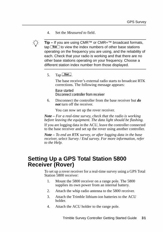
4. Set the Measured to field.
B Tip – If you are using CMR™ or CMR+™ broadcast formats, tap Ü to view the index numbers of other base stations operating on the frequency you are using, and the reliability of each. Check that your radio is working and that there are no other base stations operating on your frequency. Choose a different station index number from those displayed.
5. Tap x .
The base receiver’s external radio starts to broadcast RTK corrections. The following message appears:
Base startedDisconnect controller from receiver
6. Disconnect the controller from the base receiver but do not turn off the receiver.
You can now set up the rover receiver.
Note – For a real-time survey, check that the radio is working before leaving the equipment. The data light should be flashing.If you are logging data in the ACU, leave the controller connected to the base receiver and set up the rover using another controller.
Note – To end an RTK survey, or after logging data in the base receiver, select Survey / End survey. For more information, refer to the Help.
3.2 Setting Up a GPS Total Station 5800 Receiver (Rover)
To set up a rover receiver for a real-time survey using a GPS Total Station 5800 receiver:
1. Mount the 5800 receiver on a range pole. The 5800 supplies its own power from an internal battery.
2. Attach the whip radio antenna to the 5800 receiver.
3. Attach the Trimble lithium-ion batteries to the ACU holder.
4. Attach the ACU holder to the range pole.
Trimble Survey Controller Getting Started Guide 31

GPS Survey
5. Attach the ACU to the holder. For more information, see page 2.
6. Turn on the 5800.
7. Turn on the ACU and start Trimble Survey Controller.
8. Connect to the 5800 receiver using Bluetooth™ wireless communications:
a. From the main menu, select Configuration / Controller / Bluetooth.
b. Tap Config. and enable Bluetooth. Tap w .
c. Select Scan to locate the 5800 receiver.
d. When the scan is complete, select the 5800 receiver from the list and tap C.
3.2.1 Starting a rover surveyNote – Start the base receiver before you start a rover survey. To start a survey:
1. Make sure that the required job is open. The name of the current job appears in the title bar of the main menu.
2. From the main menu, select Survey, then select a survey style from the list. This must be the same survey style as that used for the base survey.
3. To start the rover receiver for a real-time survey, select Start survey.
A Survey menu appears with items specific to the chosen survey style, including Start base receiver and Start survey. The first time that you use this survey style, the Style wizard prompts you to specify the equipment you are using.
4. If necessary, initialize the survey.
For an RTK survey, initialize before starting centimeter-level surveying. If you are using the OTF option, the survey automatically starts to initialize using the OTF initialization method.
Once the survey is initialized, you can perform a site calibration, stakeout, or measure points.
32 Trimble Survey Controller Getting Started Guide

C H A P T E R
4Data Transfer 4
In this chapter:
■ Using the Data Transfer utility
This chapter describes how to use the Trimble Data Transfer utility to transfer data between the ACU and an office computer.Install the Data Transfer utility from the Trimble Survey Controller CD to ensure that you have the latest version. Refer to the Trimble Survey Controller or Data Transfer Help for information on:
• connecting to a Trimble controller
• transferring files
• using Microsoft ActiveSync
4.1 Using the Data Transfer UtilityTo transfer files using Data Transfer:
1. Put Trimble Survey Controller into File Transfer mode:
a. Turn on the controller and run the Trimble Survey Controller software.
b. From the Files menu, select Import/Export / Trimble PC Communications.
The following message appears: Waiting for PC Connection
When you connect to the device in Data Transfer, the following message appears:Connected to PC

Data Transfer
c. Connect the ACU to the office computer.
Note – If Microsoft ActiveSync is installed on the office computer, clear the Allow serial cable or infrared connection to this COM port check box in the ActiveSync Connection Settings dialog. For more information, refer to the ActiveSync Help.
2. Connect to the controller using the Trimble Data Transfer software. To do this:
a. Run Data Transfer. (Select , then Programs / Trimble Data Transfer / Data Transfer.)
b. In the Devices list, select the appropriate Trimble Survey Controller device.
The Data Transfer software connects to the ACU.
3. Select the files to transfer. For example, to receive a file:
a. Select the Receive tab and click Add.
The Open dialog appears.
b. Select the file type and files to transfer. Click Open.
c. Click Transfer All.
The files are transferred.
34 Trimble Survey Controller Getting Started Guide

A P P E N D I X
AMenu Structure A
Table A.1 shows the Trimble Survey Controller main menu structure.
Table A.1 Main menu structure
Name / Icon Menu / Sub-menu
Files New jobOpen jobReview current jobMap of current jobProperties of current jobCopy between jobsImport/Export
Trimble PC communicationsSend ASCII dataReceive ASCII data
Key in PointsLinesArcsBoundaryRoadsTemplatesNotes

Menu Structure
Survey
Items depend on the type of survey you are doing
Start base receiverStation setupStart surveyMeasure pointsMeasure roundsContinuous topoStation and offset
MeasureStakeout
StakeoutPointsLinesArcsDTMsRoads
Site calibrationSwap base ReceiverStart RoboticEnd survey
Table A.1 Main menu structure (Continued)
Name / Icon Menu / Sub-menu
36 Trimble Survey Controller Getting Started Guide

Menu Structure
Configuration
Items depend on the survey style you select
ControllerTime/dateLanguageSound events
Feature and attribute librariesSurvey Styles
Rover optionsTopo pointsRover radioBase optionsBase radioLaser rangefinderFastStatic pointObserved control pointRapid pointContinuous pointsStakeoutInstrumentRoundsSite calibrationPP initialization timesDuplicate point tolerancesTraverse optionsOptions
Table A.1 Main menu structure (Continued)
Name / Icon Menu / Sub-menu
Trimble Survey Controller Getting Started Guide 37

Menu Structure
Cogo Compute inverseCompute pointCompute areaCompute azimuthCompute distanceSubdivide a lineSubdivide an arcTraverse
Instrument
Items depend on the type of instrument the Trimble controller is connected to.
SatellitesReceiver files
Import from receiverExport to receiver
PositionReceiver statusOptionsNavigate to pointElectronic levelDirect ReflexInstrument controlsTracklightAutolockRadio SettingsInstrument SettingsAdjust InstrumentSurvey Controller Basic
Table A.1 Main menu structure (Continued)
Name / Icon Menu / Sub-menu
38 Trimble Survey Controller Getting Started Guide


![Skaffold - storage.googleapis.com · [getting-started getting-started] Hello world! [getting-started getting-started] Hello world! [getting-started getting-started] Hello world! 5](https://img.dokumen.tips/doc/110x75/5ec939f2a76a033f091c5ac7/skaffold-getting-started-getting-started-hello-world-getting-started-getting-started.jpg)


