Embed Size (px)
Citation preview

Fluke 192B - 196B/C - 199B/C ScopeMeter
Getting Started
4822 872 30701 Sep 2002 Rev.2 12/04 © 2002 Fluke Corporation, All rights reserved. Printed in the Netherlands All product names are trademarks of their respective companies.


i
Table of Contents
Title Page Unpacking the Test Tool Kit ........................................................................................... ii Introduction .................................................................................................................... 1 Contacting Fluke ............................................................................................................ 1 Safety Information: Read First........................................................................................ 1 Preparing for Use ........................................................................................................... 4 Powering/Resetting the Test Tool .................................................................................. 4 How to Navigate a Menu (example) ............................................................................... 4 Changing the Information Language .............................................................................. 5 Adjusting Contrast and Brightness ................................................................................. 5 Using the Scope............................................................................................................. 5 Multimeter ...................................................................................................................... 7 Recorder Functions ........................................................................................................ 8 Replay ............................................................................................................................ 8 Zoom .............................................................................................................................. 9 Making Cursor Measurements ....................................................................................... 9 Triggering ....................................................................................................................... 10 Saving/Printing Screens and Set-ups............................................................................. 11 User Options .................................................................................................................. 12 Sikkerhet (Norwegian Safety Text)................................................................................. 13
Sikkerhet: Les dette først........................................................................................... 13

Fluke 192B - 196B/C - 199B/C Getting Started
ii
Unpacking the Test Tool Kit The following items are included in your test tool kit:
1. ScopeMeter Test Tool 2. Battery Charger 3. 10:1 Voltage Probe Set (Red) 4. 10:1 Voltage Probe Set (Gray) 5. Test Lead Set (Red and Black),
Probe Ground Lead 6. Getting Started Manual (this
book) 7. CD ROM with complete Users
Manual 8. Shipment box (basic version
only) The -S versions also include:
9. Optically Isolated USB Adapter/Cable
10. CD ROM with FlukeView Soft-ware
11. Hard Case
43
1 2
79
10
8
11
5
(2x)
(2x)(2x)
6
e
(1x)f
(2x)b
(2x)ab
a c(2x)
d
Figure 1. ScopeMeter Test Tool Kit

1
Getting Started
Introduction This Getting Started Manual provides basic information on Models 192B, 196B, 196C, 199B and 199C. Refer to the Users Manual on the accompanying CD-ROM for complete operating instructions.
Contacting Fluke To locate an authorized service center, visit us on the World Wide Web at: www.fluke.com or call Fluke using any of the phone numbers listed below:
+1-888-993-5853 in the U.S.A and Canada +31-40-2675200 in Europe +1-425-446-5500 from other countries.
Safety Information: Read First The Fluke Models 192B, 196B, 196C, 199B and 199C ScopeMeter test tools (hereafter referred to as “test tool”) comply with:
• ANSI/ISA S82.01-1994 • EN/IEC61010-1 : 2001 • CAN/CSA-C22.2 No.1010.1-92 • 1000 V Measurement Category II, 600 V
Measurement Category III, Pollution Degree 2 • UL3111-1
Use the test tool only as specified in the Users Manual. Otherwise, the protection provided by the test tool might be impaired.
A Warning identifies conditions and actions that pose hazard(s) to the user. A Caution identifies conditions and actions that may damage the test tool.

Fluke 192B - 196B/C - 199B/C Getting Started
2
Warning To avoid electrical shock or fire:
• Use only the Fluke power supply, Model BC190 (Battery Charger / Power Adapter).
• Before use check that the selected/indicated voltage range on the BC190 matches the local line power voltage and frequency.
• For the BC190/808 universal Battery Charger/Power Adapter use only line cords that comply with the local safety regulations.
Note
To accommodate connection to various line power sockets, the BC190/808 universal Battery Charger / Power Adapter is equipped with a male plug that must be connected to a line cord appropriate for local use. Since the adapter is isolated, the line cord does not need to be equipped with a terminal for connection to protective ground. Since line cords with a protective grounding terminal are more commonly available you might consider using these anyhow.
Warning To avoid electrical shock or fire if a test tool input is connected to more than 42 V peak (30 Vrms) or on circuits of more than 4800 VA:
• Use only insulated voltage probes, test leads and adapters supplied with the test tool, or indicated by Fluke as suitable for the Fluke190 ScopeMeter series.
• Before use, inspect voltage probes, test leads and accessories for mechanical damage and replace when damaged.
• Remove all probes, test leads and accessories that are not in use.
• Always connect the battery charger first to the ac outlet before connecting it to the test tool.
• Do not connect the ground spring (Figure 1, item f) to voltages higher than 42 V peak (30 Vrms) from earth ground.
• Do not apply input voltages above the rating of the instrument. Use caution when using 1:1 test leads because the probe tip voltage will be directly transmitted to the test tool.
• Do not use exposed metal BNC or banana plug connectors.
• Do not insert metal objects into connectors.

Getting Started Safety Information: Read First
3
• Always use the test tool only in the manner specified.
Max. Input Voltages
Input A and B directly ...............................300 V CAT III
Input A and B via 10:1 probe ...................1000 V CAT II 600 V CAT III
METER/EXT TRIG inputs........................1000 V CAT II 600 V CAT III
Max. Floating Voltage
From any terminal to earth ground ..........1000 V CAT II 600 V CAT III Between any terminal ..............................1000 V CAT II 600 V CAT III
Voltage ratings are given as “working voltage”. They should be read as Vac-rms (50-60 Hz) for AC sinewave applications and as Vdc for DC applications.
Measurement Category III refers to distribution level and fixed installation circuits inside a building. Measurement Category II refers to local level, which is applicable for appliances and portable equipment.
The terms ‘Isolated’ or ‘Electrically floating’ are used in this manual to indicate a measurement in which the test tool input BNC or banana jack is connected to a voltage different from earth ground.
The isolated input connectors have no exposed metal and are fully insulated to protect against electrical shock.
The red and gray BNC jacks, and the red and black 4-mm banana jacks can independently be connected to a voltage above earth ground for isolated (electrically floating) measurements and are rated up to 1000 Vrms CAT II and 600 Vrms CAT III above earth ground.
If Safety Features are Impaired
Use of the test tool in a manner not specified may impair the protection provided by the equipment. Before use, inspect the test leads for mechanical damage and replace damaged test leads!
Whenever it is likely that safety has been impaired, the test tool must be turned off and disconnected from the line power. The matter should then be referred to qualified personnel. Safety is likely to be impaired if, for example, the test tool fails to perform the intended measurements or shows visible damage.

Fluke 192B - 196B/C - 199B/C Getting Started
4
Preparing for Use At delivery, the installed NiMH batteries may be empty and must be charged for 4 hours (with the test tool turned off) to reach full charge: • use only the Fluke Battery Charger/Power Adapter
model BC190 • before use check that the BC190 voltage and
frequency range match the local line power range • connect the battery charger to the ac outlet • connect the battery charger to the appropriate input on
the test tool near Input B.
Caution To prevent decrease of the battery capacity, you must charge the batteries at least once a year.
Powering/Resetting the Test Tool Turning power on/off:
The test tool powers up in its last setup configuration.
Resetting the test tool to the factory settings:
+ Turn power off, then press and hold the USER key and turn on. You should hear a double beep.
How to Navigate a Menu (example)
Display the input A function key labels.
Show the Input A (input A) menu.
The menu example shows that the input A signal is displayed non-inverted (Normal) with full bandwidth (Full). To let input A invert the input signal, and to limit the bandwidth to 20 MHz do the following:
Highlight Inverted (inverted).
Accept Inverted + jump to the next field.
Highlight 20 MHz.
Accept 20 MHz + exit the menu.
Hiding a menu or key label:
Press the CLEAR MENU key.

Getting Started Changing the Information Language
5
Changing the Information Language During operation of the test tool messages may appear on the screen (for instance if you select a recorder function). You can select the language in which messages will be displayed.
Display the USER key labels.
Open the LANGUAGE menu to select a language.
Adjusting Contrast and Brightness
Display the USER key labels.
Enable the arrow keys for adjustment.
Adjust the contrast of the screen.
Change the backlight brightness.
Using the Scope Connect the probe(s) as shown in figure 2.
Figure 2. Scope Connections
AUTO- MANUAL ranging After an Auto Set the trace position, range, time base and triggering will be automatically adjusted to assure a stable display of virtually any waveform.
Perform an Auto Set or select Manual ranging (toggle). AUTO or MANUAL appears at the top right of the screen.
Use the light-gray RANGE, TIME and MOVE keys to change the view of the waveform manually.

Fluke 192B - 196B/C - 199B/C Getting Started
6
Scope Readings and Waveforms Automatic scope measurement results are shown as Reading 1 (READING 1) and Reading 2 (READING 2) at the upper left and right display edge.
Scope readings on (ON) or off (OFF).
on A : Reading 1 (2) is input A result. on B : Reading 1 (2) is input B result. V ac ...dB: measurement function.
Glitch Detect: glitch capture on or off. Average: waveform averaging on or off. Waveform:
Normal : normal waveform display. Persistence... : waveform persistence. Digital Persistence: persistence off, short,
medium, long, infinite (C-versions only). Envelope: envelope on, off. Dot-join: dot join on or off
Mathematics... : A+B, A-B, AxB, A vs B (XY mode), Spectrum (frequency spectrum FFT, C versions).
Reference... : compare waveforms, pass/fail testing.

Getting Started Multimeter
7
Input A and Input B Settings
Input A (B) on or off.
Input coupling AC or DC.
Probe Type: voltage, current or temperature probe. Attenuation: probe attenuation.
Probe Cal...: calibration of 10:1 probe.
Polarity: input polarity normal or inverted; variable input sensitivity. Bandwidth: bandwidth full, 10 kHz, 20 MHz.
Multimeter Connect the test leads (Figure 1, item 5) to the 4-mm safety banana jack METER input.
Figure 3. Meter connections
Select a measurement function.
Relative measurements on or off.
Automatic ranging.
Manual ranging. Use to select a range.

Fluke 192B - 196B/C - 199B/C Getting Started
8
Recorder Functions First, choose a measurement in Scope or Meter mode.
Show the recorder functions. Select a recorder function, then press to display the recorder key labels:
Start (RUN) or stop (STOP) recording.
Show the recorder options. Reference: time reference is time of day (Time of Day) or time from start (From Start). In Scope Record: Display Glitches: glitch detection on, or 10 kHz filter on. Mode: Single Sweep : stores samples until memory is full, then stops. Mode: Continuous : stores samples continuously; deletes first samples if memory is full. Mode: on Ext. ... : start (Start), stop (Stop) or continue (Run) recording if triggered via the meter input (Ext.). Run requires one trigger per division in VIEW ALL mode.
In Trend Plot: Reading 1 (2)... (Scope) or Measurement... (Meter) show the measurement function menu.
VIEW ALL : see all stored samples. NORMAL : see the most recent 9 divisions.
EXIT : exit the recorder mode.
Replay In scope mode, the test tool automatically stores the 100 most recent screens. Use REPLAY to review these screens.
From Scope mode show the REPLAY key labels.
Step through the previous screen.
Step through the next screens.
Continuously play the stored screens.
Exit the REPLAY mode.
Getting Started Zoom
9
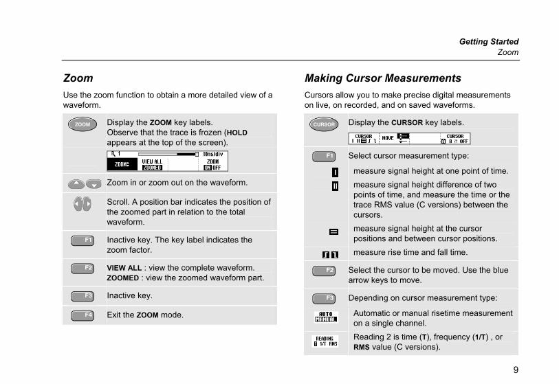
Zoom Use the zoom function to obtain a more detailed view of a waveform.
Display the ZOOM key labels. Observe that the trace is frozen (HOLD appears at the top of the screen).
Zoom in or zoom out on the waveform.
Scroll. A position bar indicates the position of the zoomed part in relation to the total waveform.
Inactive key. The key label indicates the zoom factor.
VIEW ALL : view the complete waveform. ZOOMED : view the zoomed waveform part.
Inactive key.
Exit the ZOOM mode.
Making Cursor Measurements Cursors allow you to make precise digital measurements on live, on recorded, and on saved waveforms.
Display the CURSOR key labels.
Select cursor measurement type:
measure signal height at one point of time.
measure signal height difference of two points of time, and measure the time or the trace RMS value (C versions) between the cursors.
measure signal height at the cursor positions and between cursor positions.
measure rise time and fall time.
Select the cursor to be moved. Use the blue arrow keys to move.
Depending on cursor measurement type:
Automatic or manual risetime measurement on a single channel.
Reading 2 is time (T), frequency (1/T) , or RMS value (C versions).

Fluke 192B - 196B/C - 199B/C Getting Started
10
Cursor measurements on trace A, B or M if A and B are on; M if Mathematics... is on, see ScopeReadings and Waveforms on page 6. OFF: Switch cursor measurements off.
Triggering Triggering tells the test tool when to begin displaying the waveform. Automatic triggering assures a stable display of virtually any signal:
Perform an auto set. AUTO appears at the top right of the screen. Input A is the default trigger source.
Now you can take over basic trigger controls such as source, level, slope and delay:
Display the trigger key labels
A B : trigger on input A or B waveform Ext : trigger on the meter-input signal.
Select the trigger slope (dual slope for C versions).
Select trigger level control:
• at automatic triggering via input A or B (AUTO TRIG): AUTO LEVEL : automatic level control. MANUAL : manual level control.
• at triggering via the meter input (Ext): 0.12V 1.2V : select level 0.12V or 1.2V.
• at triggering on edges via input A or B (EDGE TRIG, see F4 below): LEVEL : adjust the level manually.
Use to adjust the trigger level.
Select trigger options: Automatic... : automatic triggering on signals >1 Hz or > 15 Hz (faster).
On Edges... : turns off automatic triggering and opens the Trigger on Edge menu: Update: (screen update) □ Free Run : the test tool updates the trace
even if there are no triggers. □ On Trigger : the screen is updated only
when valid triggers occur. □ Single Shot : the test tool waits for a
trigger. After receiving a trigger, the waveform is displayed and the

Getting Started Saving/Printing Screens and Set-ups
11
instrument is set to HOLD.
Press to arm for a new trigger. Noise reject Filter: the noise reject filter reduces jitter on the screen when triggering on noisy waveforms. NCycle: Each Nth trigger results in a trace update (C versions).
Video on A... : enables triggering on video signals (input A only).
Pulse Width on A... : enables triggering on qualified pulses (input A only).
Trigger Point, Trigger Delay The trigger icon shows the trigger point. Initially you have two divisions of pre-trigger view (negative delay). To change the trigger delay, do the following:
Hold down to adjust the trigger delay.
If you move the trigger icon to the left of the screen, it changes to . The status at the bottom of the screen shows for example:
The 500ms indicates the (positive) delay between the trigger point and the waveform display.
Saving/Printing Screens and Set-ups You can save screens, recordings and setups to memory, and recall them again from memory. You can print actual or recalled screens.
Display the SAVE PRINT key labels.
SAVE : save a screen + setup (SCREEN + SETUP), or a record + setup (RECORD + SETUP) in a memory location. DELETE (ALL): Clear a selected memory or (all) memories.
RECALL SETUP: recall a setup to continue a measurement with a saved operating configuration. RECALL FOR REFERENCE: recall a screen as a reference waveform. RECALL: recall a screen + setup, or a record + setup.
Print the displayed screen. Refer to the User Options below for printer setup information.
VIEW SCREEN : view stored screens. PRINT: print a screen. EXIT VIEW : exit view mode.

Fluke 192B - 196B/C - 199B/C Getting Started
12
User Options
Display the USER key labels.
Open the options menu.
Auto Set Adjust...
Select how auto set (AUTO key) behaves: auto set on signals >15 Hz (fast response) or >1 Hz (slower response).
set input coupling to DC (Set to DC) or don’t change the input coupling setting.
set glitch detection on (Set to On) or don’t change the glitch detection setting.
Battery Save Options... When powered on the battery only, the test tool initially shuts itself down 30 minutes after you pressed a key (not in Trend Plot or Scope Record). You can set the automatic power shutdown time to 5 minutes and to 30 minutes, or you can disable the automatic power shutdown (Disabled).
Battery refresh Start a battery refresh about four times a year to keep the batteries in optimal condition. The batteries will be fully discharged and charged again.
Date adjust... Set the date (Year: Month: Day: ) and the date format (DD/MM/YY is day- month-year, MM/DD/YY is month-day-year).
Time Adjust... Set the time clock (Hours - Minutes - Seconds).
Printer Setup... Select a printer type and select the baud rate.
Factory default Clears all memories and sets the test tool to factory defaults.
Display Options...(C-Versions only) Set the display to color (Color) or black and white (Black and White).

Getting Started Sikkerhet (Norwegian Safety Text).
13
Sikkerhet (Norwegian Safety Text). Sikkerhet: Les dette først Les nøye gjennom sikkerhetsinformasjonen nedenfor før du bruker testverktøyet.
Håndboken inneholder advarsler og forsiktighetsregler der det er nødvendig å varsle om spesielle forhold.
“Advarsel” gjelder forhold og handlinger som kan medføre fare for brukeren.
“Forsiktig” gjelder forhold og handlinger som kan forårsake skade på testverktøyet.
Følgende internasjonale symboler brukes på testverktøyet og i denne håndboken:
Se forklaring i håndboken
Dobbelt isolasjon (Sikkerhetsklasse)
Informasjon om avhending
Jord
Informasjon om resirkulering Conformité
Européenne
Sikkerhets-godkjenning
Sikkerhets-godkjenning
Likestrøm (DC) Vekselstrøm (AC)

Fluke 192B - 196B/C - 199B/C Getting Started
14
Advarsel For å unngå elektrisk støt eller brann: • Bruk kun Fluke spenningsadapter modell
BC190 (Batterilader/nettadapter). • Før bruk sjekkes at det valgte/indikerte
området på BC190 er i overensstemmelse med spenning og frekvens lokalt.
• Bruk bare nettledninger som tilfredsstiller lokale sikkerhetbestemmelser sammen med BC190/808 universell batterilader/nettadapter.
Note:
For å kunne tilpasses forskjellige nettkontakter har BC190/808 universell batterilader/nettadapter en hun-kontakt som må kobles til den typen nettledning som brukes lokalt. Siden adapteren er isolert er det ikke nødvendig å ha en nettledning med jord, men disse er mer vanlige og kan brukes om ønsket.
Advarsel Slik unngår du elektrisk støt eller brann hvis testverktøyinngangen er koblet til over 42 V spiss (30 Vrms) eller kretser med mer enn 4800 VA: • Bruk kun isolerte spenningsprober,
testledninger og adaptere som følger med instrumentet, eller tilbehør som Fluke anbefaler for bruk sammen med ScopeMeter 190-serien.
• Før bruk kontrollerer du måleprobene, test-ledningene og tilleggsutstyret for mekanisk skade og bytter ut eventuelle skadede deler.
• Fjern prober, testledninger og tilleggsutstyr som ikke er i bruk.
• Husk å alltid koble batteriladeren til vekselstrømuttaket før du kobler den til testverktøyet.
• Koble ikke jordfjær (figur 1, nummer f) til spenninger høyere enn 42V spiss (30Vrms) fra jord. Ikke benytt spenninger som varierer med mer enn 600 V fra jord til noen inngang når du utfører målinger i et CAT III-miljø. Ikke benytt spenninger som varierer med mer enn 1000 V fra jord til noen inngang når du utfører målinger i et CAT II-miljø.

Getting Started Sikkerhet (Norwegian Safety Text).
15
• Ikke benytt spenninger som varierer med mer enn 600 V fra hverandre til de isolerte inngangene når du utfører målinger i et CAT III-miljø. Ikke benytt spenninger som varierer med mer enn 1000 V fra hverandre til de isolerte inngangene når du utfører målinger i et CAT II-miljø.
• Ikke benytt spenninger utover bruksområdet til instrumentet. Vær forsiktig når du bruker 1:1 testledninger fordi probespisspenningen overføres direkte til testverktøyet.
• Ikke bruk uisolerte BNC- eller banankontakter av metall.
• Ikke stikk metallgjenstander inn i kontaktene.
• Testverktøyet må bare brukes på angitt måte.
Spenningene som er oppgitt i advarslene, angis som grenser for "driftsspenninger”. De representerer V AC rms (50-60 Hz) for bruk ved AC sinuskurver og som V DC for bruk ved DC.
Måling: Kategori III gjelder distribusjonsnivå og faste installasjonskretser inne i bygninger. Måling: Kategori II gjelder lokalt nivå, noe som gjelder maskiner og bærbart utstyr.
I denne håndboken angir begrepene ‘isolert’ eller ‘elektrisk flytende’ en måling der BNC- inngangene eller banankontakten på testverktøyet er koblet til annen spenning enn jord.
De isolerte inngangskontaktene har ikke noe uisolert metall og gir full beskyttelse mot elektrisk støt.
De røde og grå BNC-kontaktene, og de røde og svarte 4 mm banankontaktene kan koples individuelt til en spenning over jord for å utføre isolerte (elektrisk flytende) målinger opptil 1000 Vrms CAT II og 600 Vrms CAT III over jord.

Fluke 192B - 196B/C - 199B/C Getting Started
16
Hvis sikkerhetsfunksjonene svekkes Hvis testverktøyet brukes på annen måte enn angitt, kan beskyttelsen utstyret gir, svekkes. Før bruk må du undersøke testledningene for mekanisk skade og bytte ut skadede testledninger!
Hvis det er mulighet for at sikkerheten har blitt svekket, må du slå av testverktøyet og koble den fra nettspenningen. Deretter bør kvalifisert personale undersøke saken. Det er sannsynlig at sikkerheten er svekket hvis testverktøyet for eksempel ikke kan utføre ønskede målinger eller det er synlige tegn på skade.


![Skaffold - storage.googleapis.com · [getting-started getting-started] Hello world! [getting-started getting-started] Hello world! [getting-started getting-started] Hello world! 5](https://img.dokumen.tips/doc/110x75/5ec939f2a76a033f091c5ac7/skaffold-getting-started-getting-started-hello-world-getting-started-getting-started.jpg)


