Embed Size (px)
Citation preview

The contents of this guide and accompanying exercises were originally created by Nemetschek Vectorworks, Inc.
2013 Getting Started G
uide

2 | Vectorworks Architect 2013 Getting Started Guide
Table of Contents
Initial Setup ............................................................................................................................................................. 3Vectorworks Preferences ......................................................................................................................................................................3Scaling the Drawing ...............................................................................................................................................................................3
Drawing the Walls ................................................................................................................................................... 4Drawing First-floor Walls ........................................................................................................................................................................4Drawing Second-Floor Walls .................................................................................................................................................................8Creating Foundation Walls ..................................................................................................................................................................12Creating the Footing ............................................................................................................................................................................15
Creating the Roofs ............................................................................................................................................... 17Creating the Roof ................................................................................................................................................................................17Creating Roof Faces ............................................................................................................................................................................19Creating the Roof Flashing Cap ..........................................................................................................................................................22Creating Main Roof Flashing ...............................................................................................................................................................22Creating Second-floor Roof Flashing .................................................................................................................................................25Creating First-floor Roof Flashing ........................................................................................................................................................26
Creating the Floors ............................................................................................................................................... 27Slab Layer Setup .................................................................................................................................................................................27First-floor Slab .....................................................................................................................................................................................27Creating the Lecture Hall Slab .............................................................................................................................................................30Creating the Second-floor Slab ...........................................................................................................................................................33
Drawing the Concrete Pads ................................................................................................................................. 35Creating Left Entrance Pads ...............................................................................................................................................................35Creating Porch Entrance and Topside Pads .......................................................................................................................................38
Inserting Doors ..................................................................................................................................................... 42Inserting First-floor Doors ....................................................................................................................................................................42Inserting Second-Floor Doors ..............................................................................................................................................................44
Inserting Windows ................................................................................................................................................ 44Inserting Second-floor Windows ..........................................................................................................................................................44Creating a Custom Window Symbol ....................................................................................................................................................47Creating a Circular Window on the First-Floor.....................................................................................................................................50Inserting First-floor Windows with the Window Tool ............................................................................................................................52
Creating the Building Entrances ......................................................................................................................... 54Creating the Front Porch Entrance ......................................................................................................................................................54Creating the Back Porch Entrance ......................................................................................................................................................57
Adding Stairs and Handrails ............................................................................................................................... 60Creating Straight Stairs .......................................................................................................................................................................60Creating a Winder Stair .......................................................................................................................................................................62Creating the Balcony Handrails ...........................................................................................................................................................65
Presenting and Annotating the Final Model....................................................................................................... 67Creating a Ground ...............................................................................................................................................................................67Creating the First Viewport ..................................................................................................................................................................68Adding a Sheet Border and Title Block ................................................................................................................................................69Adding Annotations ..............................................................................................................................................................................70

3 | Vectorworks Architect 2013 Getting Started Guide
Creating the Second Viewport .............................................................................................................................................................71Creating Elevations with Viewports .....................................................................................................................................................72Creating Section Viewports .................................................................................................................................................................73Cropping Viewports and Viewport Rendering ......................................................................................................................................74Dimensioning and Scaling Viewports ..................................................................................................................................................75Creating a Final Perspective View .......................................................................................................................................................76
Printing and Exporting to PDF ............................................................................................................................ 77

4 | Vectorworks Architect 2013 Getting Started Guide
Vectorworks Architect Getting Started Guide
Initial SetupBefore we begin drafting, let’s take a moment to set up our document. This way we can all start with the same base line.
Vectorworks Preferences 1. First, close any other Vectorworks files you may have open.
Then go to Tools > Options > Vectorworks Preferences. In the Vectorworks Preferences dialog box, choose the Session tab and click the Reset Saved Settings button. Be sure that both options in the Reset Settings dialog box are checked, and then click OK twice to close both windows.
2. Now go to File > New and choose Create Blank Document. Then click OK.
To keep things organized, we will separate our sketch from the layer we plan to use for drafting.
3. To do this, go to Tools > Organization and choose the Design Layers tab. Select the existing design layer, Design Layer 1, and click the Edit button.
4. Rename this layer from Design Layer 1 to “Scan 1”. Also click the Scale button to change the layer scale from 1:1 to 1:50. Then click OK twice to close the Edit Design Layers dialog.
5. Next, click the New button to create the second design layer.
This time name the layer Floor 1 and check the option Edit Properties After Creation. Then click OK.
6. Keep the layer scale at 1:50. Additionally, input 10’8”[3.2512m] in the Layer Wall Height field. Now click OK twice to close both windows.
By setting this value, any walls created on Floor-1 will have a default height of 10’8”[3.2512m].
7. Last go to File > Page Setup. Uncheck Show Page Breaks. Also check the option Choose Size Unavailable in Printer Setup and set the Size dropdown menu to US Arch D. Click OK to close the page setup dialog.
8. Then click Fit to Page in the View bar so that you are centered on the drawing. Our setup is complete. Now we can start drafting.
Scaling the DrawingWe will be working from a sketch of the building to create the first- and second-floor plans. So we must import the scanned PDF after we verify in the View bar that the Scan 1 layer is the active layer.
1. Now, go to File > Import > Import PDF. Choose the file “Scan Floor 1” from your exercise folder and open it. Click Import from the Import PDF dialog. You should now see the scanned PDF in the drawing area.

5 | Vectorworks Architect 2013 Getting Started Guide
Currently, if you were to try tracing this sketch with the Wall tool, you would find that the measurement from the wall you are drawing does not match the dimensions shown in the scan. To fix this we must use the Scale Objects command. To scale all objects in the drawing correctly, you only need one known length. We’ll use the longest horizontal dimension at the top of the page.
2. So let’s go to Modify > Scale Objects and choose Symmetric By Distance. Click the dimension button to the right of the Current Distance field.
This will temporarily switch you back to the drawing so that you can measure the current distance of your known length.
3. Point your cursor toward one of the endpoints of the horizontal dimension. Then press the Z key to evoke the Snap Loupe. Now that we have a clearer view of the intersection point, click to set the first point.
4. Then point your cursor at the opposite endpoint of the dimension and again evoke the Snap Loupe to get a clearer view of the intersection point.
5. This time, however, hold the Shift key before setting the endpoint in order to constrain the line horizontally. Once you see the cursor cue “Horizontal” and have the sketched dimension endpoint aligned as best possible, click to set the endpoint.
This will return you to the Scale Objects dialog. You can see the Current Distance field is now filled in with the measurement we
just took.
6. We know this is not the correct distance, so in the New Distance field input what the value of the measurement we just took should be, which is 90’ [27.432m]. Then click OK. Answer Yes to the next dialog since we need to scale the entire drawing.
Now, if we use the Constrained Dimension tool from the Dims and Notes toolset and measure the same distance again, it comes out to be 90’ [27.432m]. This means any new object we draw we will be at the correct scale also.
Drawing the Walls
Drawing First-floor WallsNow it’s time to draw our first-floor walls.
1. Choose Floor 1 from the Navigation palette to make it the active layer.
2. Then choose Show/Snap Others from Layer Options dropdown menu in the Navigation palette.
This layer option means you can see and snap to objects from other layers, but you cannot select or modify those objects in any way. We’ll start by drawing the walls for the top left portion of this building.
3. So zoom to the top left portion of the sketch using your mouse scroll wheel or the Zoom tool in the Basic tool palette.
4. Then select the Wall tool from the Building Shell toolset, and make sure the first mode, Left Control Line mode, is enabled in the Tool bar.
5. Additionally, choose the wall style “Ext CMU 10” Plain” from the

6 | Vectorworks Architect 2013 Getting Started Guide
Wall Styles dropdown menu in the Tool bar.
6. To start, click on the bottom-most point of the angled wall that is connected to the stairs.
Since we’re using Left Control Line mode, you want to click on the left side (or outer surface) of the walls. Don’t forget you can use the Snap Loupe to get the most accurate start point.
7. Then follow this wall by moving the cursor toward the vertical wall to the left.
Notice in the cursor cue 30° is displayed. This is because we have Snap To Angle selected in the Snapping palette, and one of the default angles the cursor will snap to is 30°.
8. Once you have reached the intersection point, click once to set the point.
9. Then move the cursor upward toward the horizontal wall at the top. Once you reach the intersection point and the cursor cue “Vertical” is displayed, click to set the point.
10. Next move your cursor to the right along the horizontal wall until you reach the intersecting vertical wall. Then click once the cursor cue “Horizontal” is shown.
11. Now trace this vertical wall until you reach the next intersecting wall, which is this angled wall that joins to the round wall.
12. Click at that intersection point and follow the angled wall.
13. Double-click at the intersection point of the round wall to finish.
You should now see all five of the walls we just created. Notice the Object Info palette also displays five walls. With the Wall tool still selected, let’s draw the remaining exterior walls in this section.
14. Click on the intersection point of the first wall we drew and the vertical wall that we have not yet traced. Now move your cursor vertically and click once on the horizontal wall above.
When your wall’s endpoint is connected with another wall, it only takes one click to finish the wall.
15. Do the same to draw the remaining horizontal wall along with the two angled walls to the right.

7 | Vectorworks Architect 2013 Getting Started Guide
OK, let’s see how these walls look in 3D.
16. From the View bar, enable Unified View and select Left Isometric from the Current View dropdown menu.
At the moment, the walls have no height.
17. To fix this, go to Edit > Select All and change the Top Bound dropdown menu to Layer Wall Height in the Object Info palette.
Remember, we specified the layer wall height for the Floor-1 design layer earlier. Now these walls’ height will be determined by that value.
18. Additionally, set the Bottom Bound dropdown menu to Layer Elevation.
This means that the walls’ Z height will be determined by the design layer’s elevation.
19. Next we can return to a Top/Plan view so that we can finish drawing the walls for this first-floor plan.
To start, we’ll trace the two triangular-shaped walls on the right side of the plan.
20. So just as before, select the Wall tool from the Building Shell toolset.
21. Click on the intersection points for the walls until they are complete.
Once those walls are complete, we can trace the walls in the bottom left portion of the plan. Trace the walls as shown in the screenshot below.
The interior walls in this bottom left section are thinner than the current wall style we are using, so we’ll finish tracing the other walls before we get to these walls.
22. To trace this circular wall in the middle of the plan, we need to switch to the Round Wall tool in the Building Shell toolset. Notice in the Tool bar that the wall style is already set to the same wall style we chose with the Wall tool.
So there’s no need to make the selection again, but this time we do need to choose the Three Points mode in the Tool bar.
23. Then click on the top-most endpoint near the opening in the circular wall to begin creating the wall.
24. Again, we are using the Left Control Line mode, so you need to click on the outer surface or left side of the wall to start.
8 | Vectorworks Architect 2013 Getting Started Guide
25. Your next point can be anywhere along the left side of the circular wall; but for your last point, double-click on the bottom-most endpoint near the opening in the circular wall to finish the wall.
That’s all for the exterior walls on the first floor.
26. For the remaining interior walls, switch back to the Wall tool and click the Wall Preferences button in the Tool bar. This will open the Wall Preferences dialog box.
27. From the Wall Styles dropdown menu, choose “Int-Metal Stud 3 5/8-Gyp Bd 5/8””.
28. Also, select the Insertion Options tab and change the Top Bound dropdown menu to Layer Wall Height and the Bottom Bound dropdown menu to Layer Elevation.
29. Next, we can save the parameters we just set for this wall as a custom wall style by clicking the Save Preferences As Wall Style button. Name the wall style “Aspen Interior Walls” and click OK twice to return to the drawing.
30. Now go ahead and trace the remaining interior walls.
You can draw over the wall openings for now, as we’ll add those
later on with the Door tool. Great! We just finished our first-floor walls.
31. Let’s go back to the Left Isometric view and see what we’ve got. Notice the exterior walls are still flat.
32. Go to the Basic tool palette and choose the Select Similar tool.
33. Now click on any one of the exterior walls, and all of the exterior walls will be highlighted.
34. Then in the Object Info palette change the Top Bound dropdown menu to Layer Wall Height and change the Bottom Bound dropdown menu to Layer Elevation.
You may first need to select Layer Elevation from the Top Bound drop down menu and then reselect Layer Wall Height in order to see the change.
35. We still need to change the wall height for the round wall, so press the X key to switch back to the Selection tool.
36. Click on the round wall and make the same changes to the Top and Bottom Bound dropdown menus.
We are looking pretty good, but these two selected straight walls that are supposed to meet the round wall are not joined.
37. To fix this, select the Wall Join tool from the Building Shell toolset. Make sure the first mode, T Join mode, is enabled and

9 | Vectorworks Architect 2013 Getting Started Guide
click first on the straight wall and then on the round wall. You can see now the walls are joined properly.
38. Do the same for the other straight wall that intersects with the round wall. Now let’s see what the walls look like rendered.
39. Go to the View bar and choose OpenGL from the Render Modes dropdown menu.
40. Now use the Flyover tool to inspect your other walls, and then use the Wall Join tool to join any walls that are not joined properly.
41. Then return to a Top/Plan view once you are done.
Drawing Second-Floor WallsNow that the first-floor walls are done, let’s move on to the second-floor walls. Before we create these walls we’ll need to create two new design layers and import one more PDF scan.
1. First go to Tools > Organization and select design layer “Floor 1.” Then click the New button. This will create the new design layer above the previously highlighted layer.
2. In the next dialog box, type “Floor 2” in the Name field. You can also just click OK when the edit design layers dialog box appears.
3. We need to create one more design layer for the second-floor scan, so first highlight design layer “Scan 1” and click the New button. Name the new layer “Scan 2” and click OK.
4. This time, in the Edit Design Layers dialog box set both the Elevation field and Layer Wall Height field to 0 and click OK.
5. With the new layers created you can set design layers “Scan
1” and “Floor 1” to invisible. Also be sure Scan 2 is set as the active design layer. Click OK to close the dialog box.
6. Now go to File > Import and choose Import PDF. Select file “Scan 2” from your Exercise folder. Then click Open and Import.
As you can see, the PDF is much smaller than the PDF on Scan 1. To fix this, you will need to perform the Scale Objects command.
7. So with the PDF selected, go to Modify > Scale Objects.
8. The parameters you set from the first time should still be set so all you need to do is uncheck the option Entire Drawing and click OK to scale the PDF to it proper size.
Before we begin tracing the walls from this scan, we need to make sure it’s aligned with the scan of the first floor.
9. First, set Scan 1 to visible from the Navigation palette. Then right-click design layer Scan 2 from the Navigation palette and choose Edit. Drag the Opacity slider to 50% and click OK. You should now be able to see Scan 1 below Scan 2.
10. Now, using Selection tool and the Snap Loupe, click and drag the PDF to align the second-floor scan with the first-floor plan.
11. After getting the alignment as close as possible, zoom in to the Left corner of the second-floor scan. With the PDF still selected, hold the Shift key while tapping the direction arrows to nudge the second floor until it exactly aligns with the first-floor scan.
12. Once complete, you can set design layers Scan 1 and Scan 2 to invisible.
13. Additionally, set the opacity for Scan 2 back to 100%.

10 | Vectorworks Architect 2013 Getting Started Guide
14. Then make Floor 1 the active layer from the Navigation palette.
We’ll use the walls from this design layer to create the exterior walls for Floor 2.
15. With the Selection tool, select the following walls. Be sure to hold the Shift key to select multiple objects.
16. After you select the walls, go to Edit > Copy. Next, choose Floor 2 from the Active Layer menu in the View bar.
17. Then go to Edit > Paste in Place.
18. First tap the X key twice to deselect the current walls.
19. Then set Scan 2 to visible briefly and using the Selection tool, resize the angled wall in the top left portion of the plan, so that it matches the screenshot below.
20. After resizing the wall, you can set design layer Scan 2 back to invisible.
21. Now select the Wall Join tool from the Building Shell toolset
and be sure the second mode, L Join mode, is active in the Tool bar.
22. Then click on the walls in the same order as shown in the following screenshots.

11 | Vectorworks Architect 2013 Getting Started Guide
With just a few clicks, we have all of the exterior walls drawn for this floor.
23. Set design layer Scan 2 back to visible to so that we can create the rest of the walls for this floor.
24. Select the Wall tool from the Building Shell tool set and choose Aspen Interior Walls from the Wall Styles dropdown menu.
25. Then trace all of the interior walls as shown in the screenshot.
As you’re tracing the walls, you can press the U key to cycle through the wall alignment modes in the tool bar to make tracing easier. Additionally, don’t forget to use the Snap Loupe to get a closer view when necessary. Here’s what you should have once
you’re done.
For the last set of walls in the lower left rooms, we need to use the Split tool and the Wall Join tool to create openings.
26. First we’ll use the Split tool in Point Split mode. Just click the highlighted wall somewhere around these two areas.

12 | Vectorworks Architect 2013 Getting Started Guide
The wall is now split at these 2 points, leaving the resulting wall still selected.
27. We don’t need this portion, so press the Delete key to remove it.
28. Next, switch to the Wall Join tool and make sure L Join mode is active in the tool bar. Then click on the walls in the same order as shown in the screenshots.
29. After this, you’ll also need to switch to the X Join mode in the tool bar and click on these walls in the same order as in the screenshot.
For the last wall you just cliked, we’ll also use the Wall End Cap tool in Component Wrap mode to properly cap the wall.
30. Click on one side of the wall and then the other to create the wall end cap.
Now lets clean up the wall some before we move on.
31. First set the Scan 2 layer to invisible in the Navigation palette.
If you look closely, you’ll see some wall breaks in these walls that are from the first-floor walls that do not apply here.
32. So select the Remove Wall Break tool from the Building Shell toolset, and draw a marquee around these areas to remove the wall breaks.

13 | Vectorworks Architect 2013 Getting Started Guide
33. Next let’s take care of these wall joins by using the Wall Join tool in T Join mode.
That’s all for the second-floor walls.
34. Choose OpenGL from Render modes dropdown menu in the View bar.
35. Now take a second using the Flyover tool to inspect your other walls and join any that are not joined properly with the Wall Join tool. Be sure to use the correct join mode.
36. Additionally, if any of the walls are not the correct height, go the Object Info palette and change the Top Bound dropdown menu to Layer Wall Height and the Bottom Bound dropdown menu to Layer Elevation.
37. Once you have double-checked the walls, return to a Top/Plan view.
Creating Foundation WallsJust as you’ve done for the other floors, we need to create one more design layer for the foundation.
1. Go to Tools > Organization and first set Floor 2 to invisible under the Design Layers tab. Also make Floor 1 the active layer.
2. Next, click the New button and name the new design layer “Foundation.” Make sure Edit Properties After Creation is checked. Then Click OK.
3. In the Edit Design Layers dialog box, set the Elevation field to -6’0” [-1.8288m] and the Layer Wall Height field to 72” [1.8288m]. Also change the Stacking Order fied to 3. Once complete, click OK twice to return to the drawing.
The design layer is set. Now you need to create the wall styles that will be used for the Foundation walls. We’ll begin with the Foundation wall style.
4. Select the Wall tool from the Building Shell toolset. Also, click the Wall Preferences button found in the Tool bar.
5. Then, choose Ext-CIP-Conc 12”-EIFS Imperial from the Wall Styles menu across the top of the Wall Preferences dialog box.
6. Next, in the Components section, delete the last components, LG Metal Framing and Gypsum Board.

14 | Vectorworks Architect 2013 Getting Started Guide
7. Additionally, switch to the Insertion Options tab and set the Top Bound dropdown menu to Layer Wall Height and the Bottom Bound dropdown menu to Layer Elevation.
We’ll also give this wall style to a new class.
8. To do this, choose New from the Class dropdown menu. In the New Class dialog box that appears, type “Wall-Foundation” into the Name field and Click OK.
So that this custom wall style will be available for use later on, we need to save the wall style.
9. To save the current wall style, just click the Save Preferences as Wall Style button, and name the wall style. In this case, we’ll name the wall style “Ext-CIP Conc 12”-Foundation.”Then click OK.
Now our foundation wall style is saved.
10. Then click OK twice to return to the drawing. Now we’re ready to make the foundation walls.
We’re going to use the existing walls from Floor 1 to create the foundation walls.
11. First verify that Floor 1 is the active class in the Navigation palette; also change the Layer Options dropdown menu to Active Only.
This option means that only the objects on the active layer can be
seen, selected and modified.
12. Okay, after setting layer options go to Edit > Select All to select all objects on Floor 1. Notice the Object Info palette displays 34 walls.
13. Now, copy these selected walls by either going to Edit > Copy or pressing Command + C (Macintosh) or Ctrl + C (Windows).
14. Next, set the design layer “Foundation” to the active layer.
15. Then go to Edit > Paste in Place.
This will paste a copy of the walls on the Foundation layer at the exact same coordinates as the walls on Floor 1. We don’t need the interior walls shown in the bottom left area of the building.
16. To easily remove these walls, tap the X key twice. Then select the Select Similar tool from the Basic tool palette.
17. Click the Preferences button in the Tool bar and check the option Class. Then click OK to return to the drawing area.
18. Now simply click on any one of these interior walls, and all of them will be selected.
Adding that additional option in the Select Similar Preferences dialog box means that only walls in the same class would be highlighted instead of all walls from any class.
19. Again, notice the Object Info palette. It should now display seven walls, all of which are assigned the Wall-Interior class.
20. To remove these walls simply press the Delete key.

15 | Vectorworks Architect 2013 Getting Started Guide
21. Next, press Command + A (Macintosh) or Ctrl + A (Windows) to select all of the remaining walls.
22. Now from the Object Info palette, set the Class dropdown menu to Walls–Foundation.
Although you have the walls set to the proper class, you still need to change the wall style to the foundation wall style we created earlier.
23. At the moment, all of the walls should still be selected, so in
the Object Info palette choose Replace from the Style dropdown menu.
24. From the Wall Replacement dialog box choose Ext-CIP Conc 12”-Foundation from the dropdown menu in the top right corner.
25. Additionally you’ll need to select alignment for the current wall style in reference to the replacement wall style. For this instance, you can set choose the component CMU-10” from the window on the left and component CIP Concrete from the window on the right.
26. Also, choose Left Line for both wall styles and check Replace Height, Replace Class, and Replace Textures if they are not already checked. Then click OK to replace the current wall style.
27. After replacing the wall style, we’ll need to use the Wall Join tool in L Join mode to clean up some of the wall joins.
28. As we have done previously, please click the walls in the same order as performed here to create the proper wall joins.

16 | Vectorworks Architect 2013 Getting Started Guide
29. Continuing using the Wall Join tool for the remaining triangular walls on the right side of the drawing as well.
30. We also need to resize a few of these walls, including resizing the round wall so that it’s completely closed.
With that, the Foundation Layer is complete. Now all that’s left to do is create a footing for the building.
Creating the FootingThe walls we’ve created for the foundation will be in the same place for the footing, but we will need to use a different wall style for the footing. To begin, let’s create the wall style needed for the footing.
1. First, choose the Wall tool from the Basic tool palette and click the Wall Preferences button in the Tool bar.
2. Next, select Ext-CIP Conc 12”-Plain from the Wall Styles dropdown menu.
3. Select the only component shown in the Components section and click the Edit button and set the Thickness field to 36” [0.9144m]. Then Click OK.
4. Now switch to the Insertion Options tab. Set the Top Bound dropdown menu to Layer Wall Height and the Bottom Bound dropdown menu to Layer Elevation.
5. Additionally, from the Class dropdown menu choose New, and name this class “Wall–Footing.” Uncheck Edit Properties After Creation and click OK to return to the Wall Preferences dialog.
6. Last, click the Save Preferences as Wall Style button, and name the Wall Style “Ext-CIP-Conc 36”-Footing” and click OK twice to return to the drawing.
Since the layout of the walls will basically remain the same as the Foundation design layer, we can simply duplicate that layer.
7. To do this, go the Design Layers tab in the Organization palette by clicking the shortcut button in the View bar.
8. Now, select the Foundation design layer and click Duplicate. The new design layer should appear with the name “Foundation-2.” Select the design layer and click Edit.
17 | Vectorworks Architect 2013 Getting Started Guide
9. Next, change the name of this design layer to Footing. Also set the Stacking Order field to 4. This will place the Footing layer directly below the Foundation layer.
10. Additionally, input -7’0” [2.1336m] in the Elevation field and 1’0” [0.3048m] in the Layer Wall Height field. After making these changes, click OK twice to return to the drawing.
11. At the moment, the Foundation layer is the active design layer. Go to the Navigation palette and make the Footing layer the active layer.
Remember, the layer options are set to Active Only, so only the objects from the Footing layer are showing which are the exact same walls from the Foundation layer—since we duplicated that layer. Now we need to change the wall style for these walls to the correct type for a building footing.
12. Just as you did for the Foundation walls, go to Edit > Select All or use the keyboard shortcut Command + A (Macintosh) or Control + A (Windows). In the Object Info palette you should see there are 27 walls selected.
13. Also in the Object Info palette, go to the Style dropdown menu and choose Replace.
14. When the Wall Replacement dialog box populates, choose Ext-CIP Conc 36”-Footing from the dropdown in the top right corner of the dialog.
15. Now select the CIP Concrete component for both walls in the Align section.
16. You also need to select Center for the alignment of both styles. Then click OK to change the wall style.
Again, you can see when you make this change, we need to clean up these walls a little.
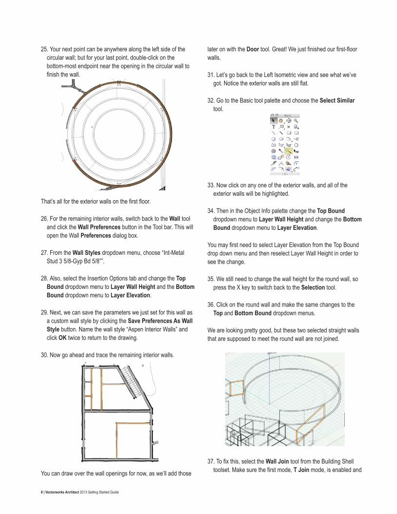
First, we need to fix the joins where the short walls are overlapping.
Let’s start with the walls in the top right of the drawing first. Although it is difficult to see, there are three walls overlapping each other.
17. Press the X key twice to switch to the Selection tool and deselect the current selection. Select one of the three walls.
18. Then press the Delete key to remove it.
19. Repeat this step again so that there is only one wall remaining.
20. Now select the wall that remains and go to the Object info palette. Click the Polar grid button at the bottom.
21. Next, choose the center position point and change the Angle field to 180°. Now the wall should sit horizontally.
Now let’s fix the area with the overlapping walls toward the
18 | Vectorworks Architect 2013 Getting Started Guide
bottom of the building.
22. Delete the two walls that are not joined to the adjacent horizontal wall.
23. Then select the remaining wall and switch to the Polar grid in the Object Info palette.
24. This time, choose the left-most position point and set the Angle field to 90°. The wall should now be perpendicular to the adjacent wall. You may need to rejoin this wall to the horizontal wall after performing this action with the Wall Join tool.
25. Repeat these steps once for the overlapping walls toward the top center of the building.
26. Then last thing we need to do to finish cleaning up the Footing walls is use the Wall Join tool to join any walls that are not properly joined.
27. Once you’re done cleaning up the joins, go to the Navigation
palette and set the Layer Options back to Show/Snap/Modify Others and make all layers visible except for the two scan layers.
28. Now, go to View > Unified View, unless the option is now already checked.
In a unified view, Vectorworks aligns all visible design layers in the drawing file with the active layer and stacks all layers in the Z direction according to their Elevation values.
29. To see this more clearly, switch to a Right Isometric View.
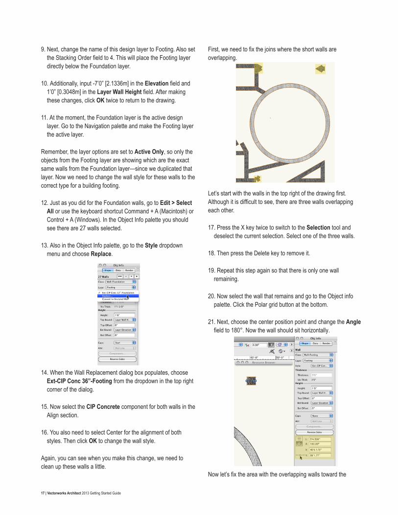
30. Now let’s take a second to render in OpenGL and use the Flyover tool to see what we’ve go so far. When you’re done return to a Top/Plan View.
Creating the Roofs
Creating the RoofNow that we have all our walls in place, it’s time to create the roof for our building. As we’ve done with the other floors, we need to create a separate design layer for the roof.
1. Instead of going to Tools > Organization and clicking the Design Layers tab, we’ll use the shortcut found in the View bar to the left of the Active Layer dropdown menu.
2. Highlight the design layer, Floor 2, and click the New button in order to create the new layer above the highlighted layer.
3. Name the new layer “Roof.” Make sure the option Edit Properties After Creation is checked and click OK.
4. In the Edit Design Layers dialog box, set the Elevation field to 22’8” [6.9088m] and the Layer Wall Height field to 2” [0.6096m]. Once these parameters are set, click OK.
5. Next, in the Organization dialog box, set Floor 1, Foundation, Footing, Scan 1, and Scan 2 design layers to invisible.

19 | Vectorworks Architect 2013 Getting Started Guide
6. Additionally make Floor 2 the active design layer. Then click OK to return to the drawing area.
We will base the roof we’re creating on the existing exterior walls from Floor 2. In order to create the correct roof profile shape, the exterior walls must create a closed shape. Therefore we’ll need to temporarily place a wall in this area so that the walls create a closed shape.
7. To do this, select the Wall tool. Then from the Tool bar, choose Virtual Wall from the Wall Styles dropdown menu.
8. Next, click this wall intersection and draw a vertical wall by holding the Shift key and double-clicking once you reach the wall below to create the virtual wall.
Now, we can create the roof profile from these walls.
9. Select the Polygon tool from the Basic tool palette, and choose Outer Boundary mode.
10. With your mouse button depressed, circle the main portion of this building but exclude the small triangular room in the bottom right, as shown in the screenshot.
11. Release your mouse button once you have reached your starting point or have completely circled the building. Notice in the Object Info palette a polygon has been created from the walls.
12. Click the Fill Style color in the Attributes palette to set the polygon’s color to a shade of light gray that is to your liking.
Next we need to offset the roof so that is sits on the inner face of the wall.
13. For this we’ll use the Offset tool in the Basic tool palette. In the tool bar choose Offset by Distance mode and Offset Original Object mode. Also set the Distance field to 10” [0.254m] in the tool bar.
14. Click anywhere inside the selected polygon to offset the shape by 10” [0.254m]. After performing this offset, you may see a small portion has extra vertices, which we don’t want.
If you do not have any extraneous points in your polygon after performing the offset, please skip to the section Creating Roof Faces.
15. To get rid of these vertices, zoom to this area and switch to the Reshape tool in the Basic Tool palette. Choose the first mode, Move Polygon Handles mode, and click this vertex point (highlighted in the below screenshot). Then move the cursor upward while holding the Shift key until you snap to the line above it.
16. When the cursor cue “Object/Vertical” appears, click again to set the vertex point. Now you need to remove these area vertex points.

20 | Vectorworks Architect 2013 Getting Started Guide
17. Since you will be removing vertices, choose Delete Vertex mode from the Tool bar. Then click once on the extra vertex point to remove it. Doesn’t that look better?
Creating Roof FacesNow that the roof shape is complete, we need to create a few smaller portions of the roof.
1. First, switch to the Selection tool and delete the virtual wall we created previously.
2. Also, you can select the polygon we’ve just drawn and move it to the Roof layer.
3. After you select the polygon, choose Roof from the Layer dropdown menu in the Object Info palette.
4. Additionally, let’s choose Roof from the Active Layer dropdown menu in the View bar to make it the active layer.
5. Now, you can choose the Polygon tool from the basic tool palette, but this time switch to the first mode, Vertex mode, in the Tool bar.
6. Then create a triangle by clicking on these three points in the order shown in the following screenshot.
7. Click once more on point 1 to create the polygon.
We also need to create a roof from the room in the bottom right portion of the building.
8. To do this, we’ll use the Polygon tool in the second mode, Inner Boundary mode.
9. Now, make Floor 2 the active Design layer in the Navigation palette.
10. Then just click inside these three walls to create the polygon.
11. With the polygon selected, change the Layer menu in the Object Info palette to Roof.
12. To create the last section of the roof, you need to make Floor 1 visible.
As you can see, there are two areas where the circular walls extend past the current roof. Therefore, we’ll need to create two more polygons for the roof in this area.
13. First select the Arc tool from the Basic tool palette. Also choose the second mode in the Tool bar, Three Points mode.

21 | Vectorworks Architect 2013 Getting Started Guide
14. When you see the cursor cue “Object/Object,” click at the point where the vertical wall and the round wall intersect.
15. Your next click can be anywhere along the inside edge of the round wall.
16. Then click on the opposite end of the curve once you see the cursor cue “Object/Object” to create the arc.
17. Set the fill for this arc to None in the Attributes palette.
18. Now select the Line tool in the Basic tool palette and click on both endpoints of the arc you’ve just drawn. You’ll know you have successfully snapped to the endpoint when you see the cursor cue “Arc End.”
You’ll need to combine these two objects to create a polyline.
19. To do this, hold the Shift key and select both the line and arc.
(The Object Info palette should display two objects.)
20. Then, go to Modify > Compose. After completing this operation, the Object Info palette should now display Polyline.
21. Now simply use these steps to create the same polyline over the remaining portion of the round wall.
22. After converting these objects hold the Shift key to select both. Change the polylines Fill style from None to Solid in the Attributes palette.
23. Also in the Attributes palette, and click the Fill Style color to set the polygon’s color to the same shade of gray that you applied to the larger polygon.
Now it’s time to covert these polygons and polylines into roof faces.
24. To start, make design layer Roof the active layer in the Navigation palette.
25. Select the largest polygon that covers the main building. Then, go to AEC > Roof Face.
26. In the Create Roof Face dialog box, choose Rise Over Run for the Roof Slope.
27. Also choose Vertical for the Edge Miter and Hole Miter. Additionally, input the following values: -24” [0.6096] for the Axis Z field, 0” [0m] for the Rise field, 1” [0.0254m] for the Run field, and 4” [0.1016] for the Thickness field. Click OK.
Next, we need to draw a line that defines the roof’s slope.
28. So click anywhere inside the polygon, and move your cursor downward while holding the Shift key.
29. When the cursor cue “Vertical” appears, click to complete the

22 | Vectorworks Architect 2013 Getting Started Guide
line.
You should now see a black arrow displayed with the line.
This arrow indicates which side of the object will be the raised side of the roof.
30. Move your cursor to the right of the line so that the arrow points in this direction as well. Then click again.
The arrow should turn blue, which indicates that the roof face is complete. Again, notice in the Object Info palette that the object is now displayed as a roof face.
Okay, let’s make the triangular polygon in the bottom right area into a roof face as well.
31. Select the polygon, and then again go to AEC > Roof Face.
32. In the Create Roof Face dialog, all of the parameters we set previously should have been retained, so all you need to do is click OK.
33. To create the roof axis line, draw a vertical line along the right edge of the polygon.
34. Once you draw the axis line, move your cursor to the right of the line so that the black arrow also points to the right. Then click to complete the roof face.
35. Now, select the triangular polygon to the left of the main building. Once again, go to AEC > Roof Face.
This will actually be the porch roof for the entrance of the building, so it will require different parameters from the other two roof faces.
36. In the Create Roof Face dialog, set the Axis Z field to -14’2” [4.318m], the Rise field to 7/8” [0.022225m], the Run field to 1” [0.0254m], and the Thickness field to 8” [0.2032m] and click OK.
37. To draw the roof axis line, move your cursor (without clicking) to the bottom left corner of the polygon. The cursor cue “Endpoint” should be displayed.
38. Hover your cursor there until the smart point is acquired (when a red box appears around the point).
39. Then move your cursor upward. As you do this, you should see a green extension line appear along with the cursor cue “Align H”.
40. Once you have a little space between your cursor and the smart point, click to start the roof axis line. Continue moving your cursor upward while holding the Shift key.
41. When the cursor cue “Vertical” appears, click to complete the roof axis line.
42. Then click again, making sure that the black arrow is pointing to the right of the roof axis line, to create this roof face.

23 | Vectorworks Architect 2013 Getting Started Guide
43. Last,with the last roof face selected, make sure the Angle field in the Object Info palette is set to 41.19° to get it a more drastic slope.
The two polylines that cover the round wall will also be porch roofs.
44. So, select one of these polylines and go to AEC > Roof Face.
45. In the Create Roof Face dialog, set the Axis Z field to -13’ [3.9624m]. Also set the Rise field to 0” [0m], the Run field to 1” [0.3048m], and the Thickness field to 4” [1.2192m]. Click OK.
46. Now draw the roof axis line along the straight wall that shares an edge with the polyline.
47. Next, set the black arrow so that it sits to the right of the roof axis line.
48. Repeat these steps for the other polyline that covers the round wall and you’re done.
49. If they are not already visible. Make design layers Floor 1, Floor 2, and Roof the only visible layers and render in OpenGL.
50. Then use the Flyover tool to see what we’ve done.
As you are flying over your building, you should see that since you’ve made a parapet roof, the top of the interior walls from
Floor 2 are showing through the roof. We can fix this quickly with the Select Similar tool.
51. To do this first, make Floor 2 the active layer.
52. Change the Layer Options dropdown menu to Show/Snap Others. This way only the objects from Floor 2 can be selected and/or modified.
53. Next, switch to the Select Similar tool in the Basic tool palette. Also click the Select Similar Preferences button in the Tool bar.
54. Since we only want the interior walls to be selected, check the option Wall Style, uncheck the option Class and click OK.
55. With the Select Similar tool still active, click any one of the interior walls protruding through the roof. After clicking one of these interior walls, all of them will be selected.
56. Now in the Object Info palette, simply input 10’ [3.048m] in the Height field and press Enter to lock in the value. All of the interior walls should now be below your roof.
57. If there are any interior walls that still show above the roof face, simply select them and change their Height to 10’ [3.048m] in the Object Info palette as we just did here.
Now you’re done with the roofs and can return to a Top/Plan view.
Creating the Roof Flashing Cap
Creating Main Roof FlashingWith all of your roof objects completed, you’re now ready to add the flashing to these roofs. We’ll start with the flashing for the main roof.
1. Before you begin, make sure the Roof layer is your active layer and that the view is set to Top/Plan.

24 | Vectorworks Architect 2013 Getting Started Guide
2. Additionally, set the Layer Options dropdown menu in the Navigation palette to Active Only.
3. Next, with the Selection tool, select the largest roof face.
4. Then, go to Modify > Edit Roof. In Edit mode you should see the polygon used to define the shape of the roof. Select this polygon and go to Edit > Copy and click Exit Roof.
5. Now, to paste this polygon at the exact same position as the roof, go to Edit > Paste in Place. This polygon defines the path used to create the flashing cap.
Next, you need to create the profile shape that will follow that path.
6. To do this, double-click the Rectangle tool in the Basic tool palette.
7. In the Create Object dialog box, enter 12” [0.1016m] in the Width field and 4” [0.3048m] in the Height field. Check Position At Next Click. Then click OK to return to the drawing.
8. Click once more anywhere in the drawing area to place the rectangle.
9. Now zoom in so that only the rectangle is visible in your drawing area.
10. With the rectangle still highlighted, go to Modify > Decompose.
This will deconstruct the rectangle into four lines. Notice that the Object Info palette also reflects this change.
11. Double tap the X key so that the lines are deselected.
12. Then select just the bottom line and hit the Delete key.
13. You can now combine these lines into one object again. With the Selection tool, select all three lines and go to Modify > Compose to create a polygon.
14. After this, switch to the Offset tool and make sure Offset by Distance mode and Offset Original Object mode are enabled in the Tool bar.
15. Additionally, set the Distance field in the Tool bar to .5” [0.0127m].
16. Next, to offset the object, click outside of the selected polygon twice.
17. To add a little more detail to the profile shape, let’s select the Reshape tool in the Basic tool palette.
18. Enable Add Vertex mode and Corner Point mode in the Tool bar.
19. In the drawing area, click once on the bottom right vertex of the polygon.
This will add another vertex point to the polygon.
20. To set exact placement of this vertex point, press the Tab key to enter the Floating Data bar.
21. After doing this you should be able to edit the Length field.
If for some reason you have another field highlighted in the Floating Data bar, simply continue pressing the Tab key to cycle through the fields until you reach the Length field.

25 | Vectorworks Architect 2013 Getting Started Guide
22. In the Length field, enter a value of .35” [0.00889m]. Press the Enter key to lock in the value.
Notice the small dashed circle that appears around your current vertex point. This line indicates .35” [0.00889m] away from that current point in any direction.
23. Since we want this new vertex to sit at an angle, move your cursor around this dashed line until you see the cursor cue “45°/Length.” Then click to place the new vertex.
24. Repeat these steps to create an additional vertex point from the bottom left vertex of the polygon.
The path and profile for the flashing cap is ready. Next we will use the Extrude Along Path command to create the flashing.
25. Select the polygon that is on top of the main building roof.
You may need to use the Coincident selection tool to select the right object.
26. To do this, hold the J key and select the edge of the polygon.
27. Then choose Polygon from the resulting dialog box.
28. Once you’ve selected the larger polygon, hold the Shift key and select the small polygon we previously created to use as the flashing profile.
29. Now, with both polygons selected, go to Model > Extrude Along Path. The larger polygon should already be highlighted as the path object; however, if it is not, click the Previous or Next button until it is highlighted.
30. Then click OK to create the extrude along path and then double-click on the object to access the editing modes for this object.
31. You can choose to either edit Path or Profile. Choose Profile and click OK to enter the editing mode.
By default the profile for an extrude along path object is set so that the center of the profile sits at 0,0. Since the flashing cap should sit near the edge of the roof, we need to move our profile so that it is aligned accordingly.
32. To do this, select the polygon and snap it to this corner of the wall shown in gray.
33. After you’re done, click the Exit Profile button to return to the drawing.
34. To view what the flashing looks like in 3D, switch to a Right Isometric view and render in OpenGL.
You should notice the flashing cap is above the roof face object.
35. To fix this, select Extrude Along Path and enter -18” [-0.6096m] in the Z field in the Object Info palette.
26 | Vectorworks Architect 2013 Getting Started Guide
36. Then press Enter to lock in the value. Consequently, the flashing should now be in the right position.
Creating Second-floor Roof Flashing We’re done with Main Roof flashing, so now let’s create the flashing for the small second-floor roofs.
1. To begin, return to a Top/Plan view. The Layer Options dropdown menu should already be set to Active Only but if it’s not, you should make this change now.
2. Also set Floor 2 to be the active design layer in the Navigation palette.
Let’s start with the flashing for the triangular roof in the bottom right corner first .
3. In the Basic tool palette, select the Polygon tool. Also choose Inner Boundary mode and click on the space inside of the triangular roof.
As soon as you click in this area, a polygon should be created that fills the area. This will be the path for this particular roof’s flashing. Before we create an extrude along path of this object, we need to retrieve the profile from the previous extrude along path we made.
4. For the moment, set the Roof design layer as the active layer from the View bar.
5. Next, double-click the extrude along path from the main roof and choose to edit the profile.
6. With the polygon selected, go to Edit > Copy. Then click Exit Profile.
7. Switch Floor 2 back to the active layer and go to Edit > Paste.
8. With the pasted object still selected, hold the Shift key and select the polygon we just created from the triangular walls.
9. Again, go to Model > Extrude Along Path and click OK once the larger polygon is highlighted as the path object.
As we did last time, you also need to edit this extrude along path.
10. So double-click the extrude along path, choose to edit the profile and click OK.
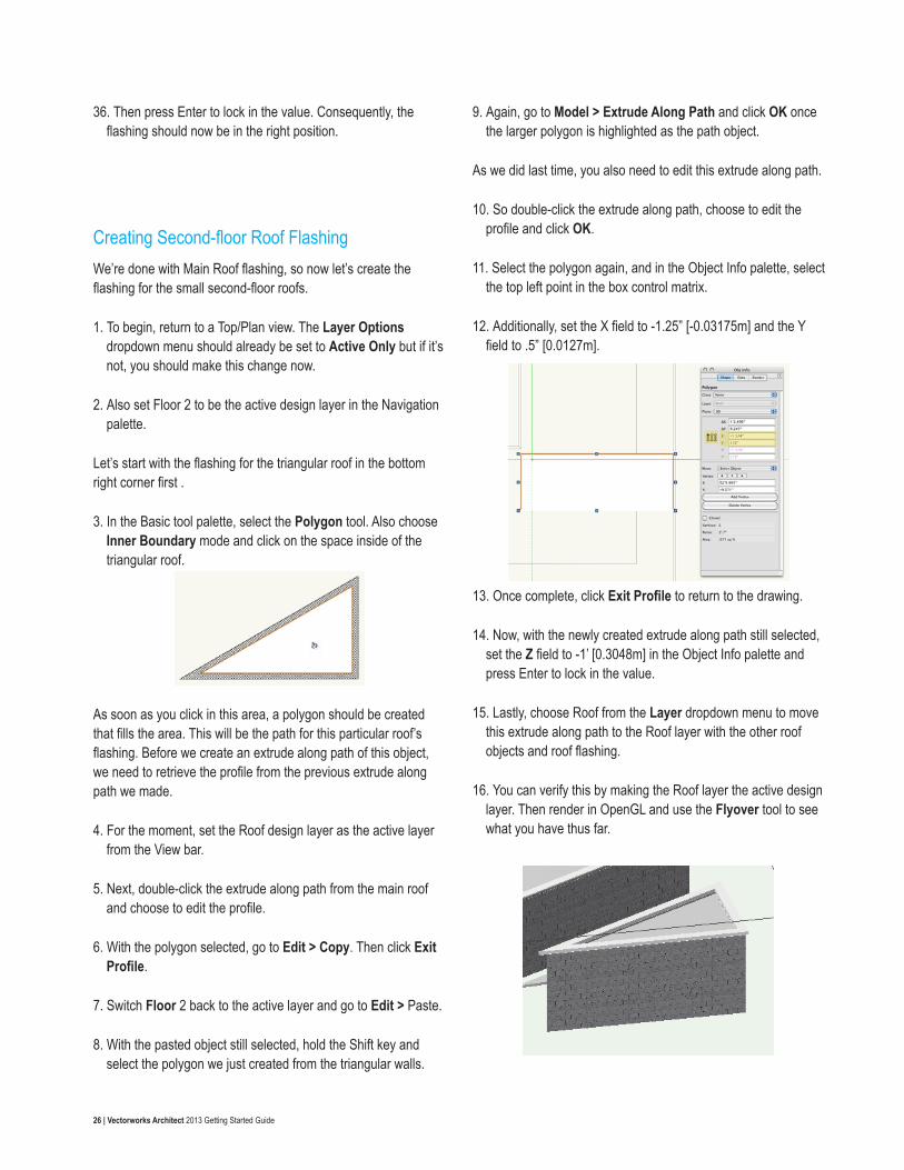
11. Select the polygon again, and in the Object Info palette, select the top left point in the box control matrix.
12. Additionally, set the X field to -1.25” [-0.03175m] and the Y field to .5” [0.0127m].
13. Once complete, click Exit Profile to return to the drawing.
14. Now, with the newly created extrude along path still selected, set the Z field to -1’ [0.3048m] in the Object Info palette and press Enter to lock in the value.
15. Lastly, choose Roof from the Layer dropdown menu to move this extrude along path to the Roof layer with the other roof objects and roof flashing.
16. You can verify this by making the Roof layer the active design layer. Then render in OpenGL and use the Flyover tool to see what you have thus far.

27 | Vectorworks Architect 2013 Getting Started Guide
Creating First-floor Roof FlashingThe last roof flashing you need to create is for the curved porch roofs that cover the walls on the first floor. So let’s get to it.
1. Switch back to a Top/Plan view. Choose Floor 2 from the Active Layer dropdown menu in the View bar.
2. Also set the Layer Options dropdown menu in the Navigation palette to Gray/Snap Other, and make sure only Floor 1 and Floor 2 are set to visible.
3. Once the layers are set up properly, zoom to the area with the round walls and select the Arc tool from the Basic tool palette.
4. Click on the outer face of the round wall where the wall intersects with the vertical wall.
5. After that, click anywhere along the outer face of the round wall.
6. To finish the arc, click at this point where the straight wall and round wall intersect again below the first arc point.
This arc will be the path for this last flashing cap. To create the
flashing cap your going to repeat the steps you used to create the triangular wall’s flashing cap.
7. For the moment, set the Roof design layer as the active layer from the View bar.
8. Next, switch to the Selection tool. Then double-click the extrude along path from the main building and choose to edit the profile.
9. With the polygon selected, go to Edit > Copy. Then click Exit Profile.
10. Switch Floor 2 back to the active layer and go to Edit > Paste.
11. With the pasted object still selected, hold the Shift key and select the arc we just created inside these walls.
12. Again, go to Model > Extrude Along Path and click OK once the arc is highlighted as the path object.
13. After the extrude along path is created, go to the Object Info palette and set the Layer drop down menu to Roof.
14. Set the Roof layer to visible in the Navigation palette and make it the active layer. When you switch to a right isometric view, you can see the flashing cap sits high above the actual roof faces.
15. To lower the extrude along path, go to the Object Info palette and enter a value of -12’ [3.6576m] in the Z field and press Enter.
There the flashing cap should be at an appropriate height now.
16. Next, press the X key twice. Then click the Fit to Objects button in the View bar to set a zoom factor that shows the entire model.

28 | Vectorworks Architect 2013 Getting Started Guide
17. Last, let’s set the layer options to Show/Snap Others and render in OpenGL.
18. As always, you can use the Flyover tool to see the progress you’ve made.
19. Return to a Top/Plan view before you move forward.
Creating the Floors
Slab Layer SetupThus far, you’ve created the walls and roofs for this model. The next step in this project is to create slabs for the first and second floors. As usual, you will need to set up two new design layers to begin—one for each slab.
Since you’ve done this a few times now, we’ll move through this process a little more quickly.
1. Go to the Design Layers tab in the Organization dialog box and select design layer Foundation. Then, click the New button.
2. In the New Design Layer dialog box, name the design layer “Slab 1.” Check Edit Properties After Creation and click OK.
3. In the Edit Design Layers dialog box, set the Elevation and Layer Wall Height fields to 0. Then click OK to create the design layer.
You need to create one more design layer for the second-floor slab.
4. To do this, select Slab 1 and click the Duplicate button. This will create a new design layer, which you should name “Slab
2,” and will be stacked directly above Slab 1.
This slab should be stacked between Floor 1 and Floor 2.
5. To change the stacking order of the design layers, click and hold the digit located to the right of the design layer name in the # column.
6. Then drag your cursor upward until a bold horizontal line appears between Floor 1 and Floor 2.
7. Now release your mouse button. As you can see, Slab 2 is now stacked between Floor 1 and Floor 2.
Aside from the stacking order, you also need to change the elevation height for Slab 2.
8. So, select Slab 2 and click the Edit button.
9. When the Edit Design Layers dialog appears, input 10’8” [3.2512m] in the Elevation field and click OK.
10. Next, set Slab 1 to be the active design layer.
11. Now, make design layers Scan 1, Slab 1, and Floor 1 visible. All other design layers should be set to invisible.
12. Click OK to close the Organization dialog box.
13. Finally, go to View > Layer Options and choose Show/Snap Others. Now we’re ready to begin drawing the slabs.
First-floor SlabJust as you did with the roof objects, you will first create the shape with basic 2D geometry and then convert it to a slab. To begin, go the Attributes palette and select any shade of tan for the Fill color.
1. To do this, simply click on the color swatch below the paint bucket icon.
2. At the bottom of the color picker select the Vectorworks Classic Colors color palette. Then select a color.
3. Additionally, in the Attributes palette, click the Opacity button, which is just below the Pen color swatch, and set the Opacity

29 | Vectorworks Architect 2013 Getting Started Guide
slider to 50%.
4. Now select the Rectangle tool from the Basic tool palette. Also choose the first mode, Rectangle mode, in the Tool bar.
5. After that, click at the top left corner of the building where the horizontal and vertical walls meet.
6. Then at the bottom right corner on the opposite end of the building click once more to create the rectangle.
Notice you can still see the walls beneath the rectangle since we set the opacity for this rectangle to 50%.
You will also notice that the rectangle extends past the building walls near the building entrance. Let’s take a second to fix this.
7. Again select the Rectangle tool in the Basic tool palette, but this time choose the last mode,Three Point Rotated Rectangle mode.
8. Now, you will need to use the scan of Floor 1 to snap to the point where the Window Wall at the entrance and the horizontal wall below that window wall meet.
9. After locating this point, click to set the first point of the rectangle.
The second mouse click will set the rectangle’s angle.
10. So move your cursor upward and slightly to the right until you reach the angled wall above.
11. When you see the cursor cue “Object/Perpendicular°,” click once to set the angle.
With the last click, you’ll set the rectangle’s width.
12. So move your cursor to the left until you have passed the left-most vertical wall of the building. Then click to create the rectangle.
You can use this newly created rectangle to clip a section from the larger rectangle you previously drew:
13. Hold the Shift key and, with the Selection tool,select both rectangles.
30 | Vectorworks Architect 2013 Getting Started Guide
14. Next, go to Modify > Clip Surface.
15. Initially, it might seem as if nothing happened, but if you press the Delete key to remove the small rectangle, you will see that the clip was successfully completed.
16. Additionally, if you select the larger rectangle, you will notice in the Object Info palette that the object has been changed to a polygon.
You will also need to clip the area inside of the round walls from the existing polygon.
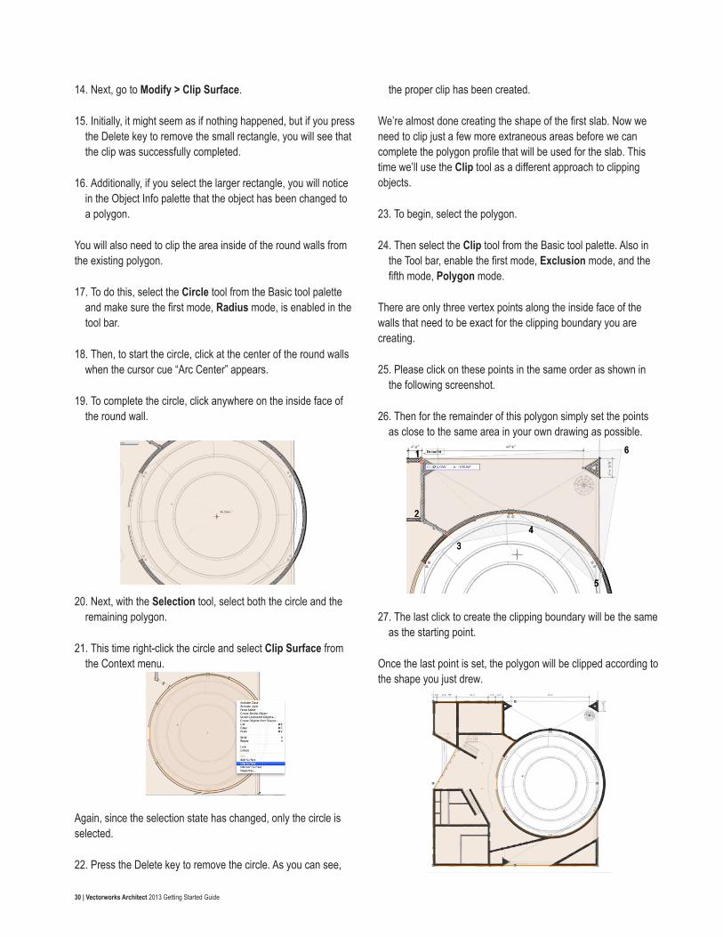
17. To do this, select the Circle tool from the Basic tool palette and make sure the first mode, Radius mode, is enabled in the tool bar.
18. Then, to start the circle, click at the center of the round walls when the cursor cue “Arc Center” appears.
19. To complete the circle, click anywhere on the inside face of the round wall.
20. Next, with the Selection tool, select both the circle and the remaining polygon.
21. This time right-click the circle and select Clip Surface from the Context menu.
Again, since the selection state has changed, only the circle is selected.
22. Press the Delete key to remove the circle. As you can see,
the proper clip has been created.
We’re almost done creating the shape of the first slab. Now we need to clip just a few more extraneous areas before we can complete the polygon profile that will be used for the slab. This time we’ll use the Clip tool as a different approach to clipping objects.
23. To begin, select the polygon.
24. Then select the Clip tool from the Basic tool palette. Also in the Tool bar, enable the first mode, Exclusion mode, and the fifth mode, Polygon mode.
There are only three vertex points along the inside face of the walls that need to be exact for the clipping boundary you are creating.
25. Please click on these points in the same order as shown in the following screenshot.
26. Then for the remainder of this polygon simply set the points as close to the same area in your own drawing as possible.
27. The last click to create the clipping boundary will be the same as the starting point.
Once the last point is set, the polygon will be clipped according to the shape you just drew.

31 | Vectorworks Architect 2013 Getting Started Guide
Let’s use the Clip tool once more to clip this bottom portion of the polygon.
28. Again just follow the order used in this screenshot to set your own points for the clipping boundary.
Remember that only the points along the walls need to be exact. The rest of the points need to be only relatively close to the area shown in the screenshot. Just as last time, your start and end points should be the same point. Once we’ve completed it again, the polygon will be clipped accordingly. Notice in the Object Info palette, because of the way the polygon was clipped; there are two polygons instead of one now. Now you’re ready to convert these polygons into a floor.
29. To start, switch to the selection tool and select the larger of the two polygons and go to AEC > Floor.
30. In the Create Floor dialog box, set the Bottom Z field to -12” [-0.3048m] and the Thickness field to 12” [0.3048m]. Then click OK to create the floor. Notice in the Object Info palette that the object is now a floor.
31. Next, select the smaller polygon and again go to AEC > Floor. You’ll use the same parameters as before, so simply click OK to create the floor.
Creating the Lecture Hall SlabThe last portion of the slab that you need to create for this floor is for the auditorium or lecture hall. Here’s what that floor in this section looks like.
Each level is 1’6” [0.4572m] higher than the level before it. This is so the people on each level can see the presenter or lecturer in the center of the floor. Therefore, instead of using the Floor command as we did before, we’ll create a sweep since this portion of the floor is cylindrical. To create a sweep, you must first make a profile shape that will sweep around our defined axis point. Additionally, to make things easier we’ll use the Floor 1 Scan as a reference to create guidelines before we perform the sweep.
1. First select the 2D Locus tool from the Basic tool palette.
2. Now click at the center of the existing round wall when the cursor cue “Arc Center” appears.
3. After setting the locus point, zoom into view so that you can see the detail in the Floor 1 scan in the auditorium.
4. Pan if necessary so that the locus point is on the left side of your drawing area.
5. Next, go back to the Basic tool palette and select the Line tool.
6. Then click to set the first point of the line when the cursor cue “Arc Center” appears.
7. Hold the Shift key and move your cursor to the right. Once the cursor cue “Horizontal” appears and your line is extended past

32 | Vectorworks Architect 2013 Getting Started Guide
the round wall, click again to create the line.
8. With the lines still selected go to Modify > Guides > Make Guide. Notice the line style has changed to a purple dashed line which is the line style used by default for guides.
Furthermore, the selection highlighting has changed to gray. The gray highlighting means your selected object is locked; which you can also see in the Object Info palette. Also in the Object Info palette, notice the lines class has changed from the None class to the Guides class, which is automatically created the first time the Make Guide command is used.
Now we need to create duplicates of this guide with spacing of 1’6” [0.4572m] between each guide.
9. For this, select the Move by Points tool in the Basic tool palette.
10. Also enable Move mode and Object Retention mode in the Tool bar and set the Number of Duplicates field to 3.
11. The line you drew earlier should still be selected but if it’s not hold the Command key (Macintosh) or the Control key (Windows) to temporarily enable the Selection tool.
12. Select the line and then release the Command or Control key.
13. After that, click on the existing locus point when the “Locus” or “Endpoint” cursor cue appears and press the Tab key to enter the Length field on the floating data bar.
14. Input 1’6” [0.4572m] and press the Enter key to lock in the value.
15. Then hold the Shift key and move your cursor upward.
16. When the cursor cue “Vertical/Length” appears, click to create the duplicate guides with this spacing.
17. Next, switch back to the Line tool in the Basic tool palette.
18. Draw a vertical line from the point where the first row of seating in the scan layer and the bottom-most horizontal guideline meet (see screenshot below).
Remember that the Scan layer does not have any snapping points, so use the Snap Loupe to set the most accurate point as possible.
19. Do the same for the remaining three rows of the scan layer.
20. Lastly, select all four of the vertical lines, and again go to Modify > Guides > Make Guide.
Creating the guides in this way will make it easier to create the sweep profile to ensure it will match the floor scan. With the guides completed, it’s time to move on to creating the actual lecture hall floor with the use of the Sweep command.
To begin, you need to create the sweep profile.
21. To do this, select the Double Polygon tool from the Basic tool palette and click the Preferences button in the Tool bar.
22. From the Double Polygon Preferences dialog box set the separation between the two lines to 4” [0.1016m].
23. In addition, choose Create Polygons from the Options section and click OK to return to the drawing.
33 | Vectorworks Architect 2013 Getting Started Guide
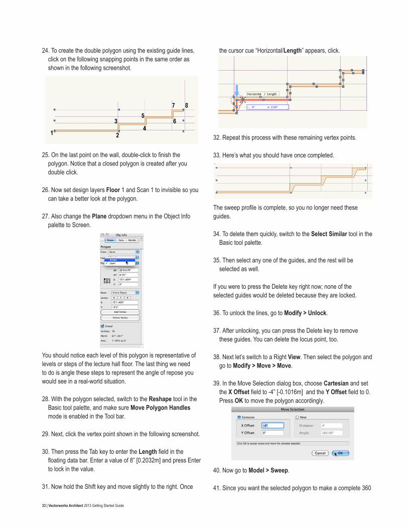
24. To create the double polygon using the existing guide lines, click on the following snapping points in the same order as shown in the following screenshot.
25. On the last point on the wall, double-click to finish the polygon. Notice that a closed polygon is created after you double click.
26. Now set design layers Floor 1 and Scan 1 to invisible so you can take a better look at the polygon.
27. Also change the Plane dropdown menu in the Object Info palette to Screen.
You should notice each level of this polygon is representative of levels or steps of the lecture hall floor. The last thing we need to do is angle these steps to represent the angle of repose you would see in a real-world situation.
28. With the polygon selected, switch to the Reshape tool in the Basic tool palette, and make sure Move Polygon Handles mode is enabled in the Tool bar.
29. Next, click the vertex point shown in the following screenshot.
30. Then press the Tab key to enter the Length field in the floating data bar. Enter a value of 8” [0.2032m] and press Enter to lock in the value.
31. Now hold the Shift key and move slightly to the right. Once
the cursor cue “Horizontal/Length” appears, click.
32. Repeat this process with these remaining vertex points.
33. Here’s what you should have once completed.
The sweep profile is complete, so you no longer need these guides.
34. To delete them quickly, switch to the Select Similar tool in the Basic tool palette.
35. Then select any one of the guides, and the rest will be selected as well.
If you were to press the Delete key right now; none of the selected guides would be deleted because they are locked.
36. To unlock the lines, go to Modify > Unlock.
37. After unlocking, you can press the Delete key to remove these guides. You can delete the locus point, too.
38. Next let’s switch to a Right View. Then select the polygon and go to Modify > Move > Move.
39. In the Move Selection dialog box, choose Cartesian and set the X Offset field to -4” [-0.1016m] and the Y Offset field to 0. Press OK to move the polygon accordingly.
40. Now go to Model > Sweep.
41. Since you want the selected polygon to make a complete 360

34 | Vectorworks Architect 2013 Getting Started Guide
with no additional pitch, you can leave all of the parameters at their defaults and click OK to create the sweep.
42. In the Navigation palette, set the Scan 1 and Floor 1 design layer back to visible and also return to a Top/Plan view.
When you switch back to Top/Plan you may see the sweep is not in the correct location.
43. To fix this, just select the sweep and drag it by its Center point to middle of the existing round wall. When the cursor cue “Arc Center” appears, release your mouse button to move the sweep to that location.
That’s it for the first-floor slabs.
44. You can set design layers Floor 1 and Scan 1 to invisible, render in OpenGL, and use the Flyover tool to see what you’ve got so far.
45. Once you’re done, return to a Top/Plan view.
Creating the Second-floor SlabThe first-floor slab is done. So we’ll be continuing on with creating the second-floor slab.
1. In the Navigation palette, set design layers Slab 2, Floor 2, and Scan 2 to be the only visible layers.
2. Also, make Slab 2 the active layer.
Just as with the first floor, much of the slab creation will rely on the following existing walls, but this time the walls we use, as a reference, will be from Floor 2. There’s only a small section that doesn’t have existing geometry to reference, and that’s the curved area; which is actually a balcony with a handrail. So let’s start by drawing the handrail shape first.
To create this curved handrail shape, you need to use Polyline tool in Point on Arc mode.
3. Select this tool from the Basic tool palette, and also select the correct mode in the Tool bar.
Take a look at the curve. You can see it’s basically composed of three arcs. With the Polyline tool in this mode, you can draw all three composed arcs in one shot instead of having to trace each arc separately and then snapping to the endpoints and compose them.
4. To begin, click on the top-most endpoint of this curved shape.
5. Next, click anywhere, along the current arc.
6. Then click somewhere near the endpoint of the current arc, which will also be the start point of the next arc in the shape.
Use the scan as a reference for the best place to set this point based on the curve of the arc. Now you can move on to the second arc in the shape.
7. Again, you’ve already set the start point, so the next click can be anywhere along the arc.
8. Then the last click defines this arc’s endpoint and the next arc’s start point.
9. Once more, click anywhere along the last arc, and double-click at the arc’s endpoint to create the polyline.

35 | Vectorworks Architect 2013 Getting Started Guide
There. You’ve created the handrail profile in just a few short clicks.
10. You can now switch to the Polygon tool in the Basic tool palette to finish creating the rest of the floor profile.
11. Also enable the first mode, Vertex, mode.
12. First, click at the top-most endpoint of the polyline you just created and hold the Shift key while moving your cursor upward.
13. Then double-click on the inside face of the first wall you reach.
14. With the Polygon tool still active, click on the bottom-most endpoint of the curved polyline and follow the straight line that is connected to the curve in the scan layer.
15. After the cursor cue “30.00°” appears, click somewhere near the endpoint of the line to match the scanned layer.
16. Now double-click the inside endpoint of the wall located to the top left of your current point.
17. Next, press the X key to switch to the Selection tool.
18. Select the curved polyline and the two polygons we just created, and go to Modify > Compose. The objects should be composed into one polyline, as reflected in the Object Info palette.
19. At this point you can switch back to the Polygon tool in the Basic tool palette to complete the floor profile. Also enable Vertex mode in the Tool bar, if it is not already enabled.
The remainder of the vertices should be relatively quick to create, as they are snapable points from the inside face of the walls from the second floor.
20. For that reason you can set design layer Scan-2 to invisible in the Navigation palette.
21. Furthermore, please set your vertex points to the same location and in the same order as shown in the following screenshot. Don’t forget to double-click on your endpoint to complete the polygon.
22. Switch to the Selection tool.
23. Hold the B key to enable X-ray Fills mode. While holding the B key, select your newly drawn polygon and the curved polyline and again go to Modify > Compose to convert these two objects into one large polyline.
As you can see, this is only a portion of the remaining slab.
24. So again enable the Polygon tool in the Basic tool palette and follow the vertex points set in the screenshot and set these same points in your file. For this polygon return to the start point to complete the shape.
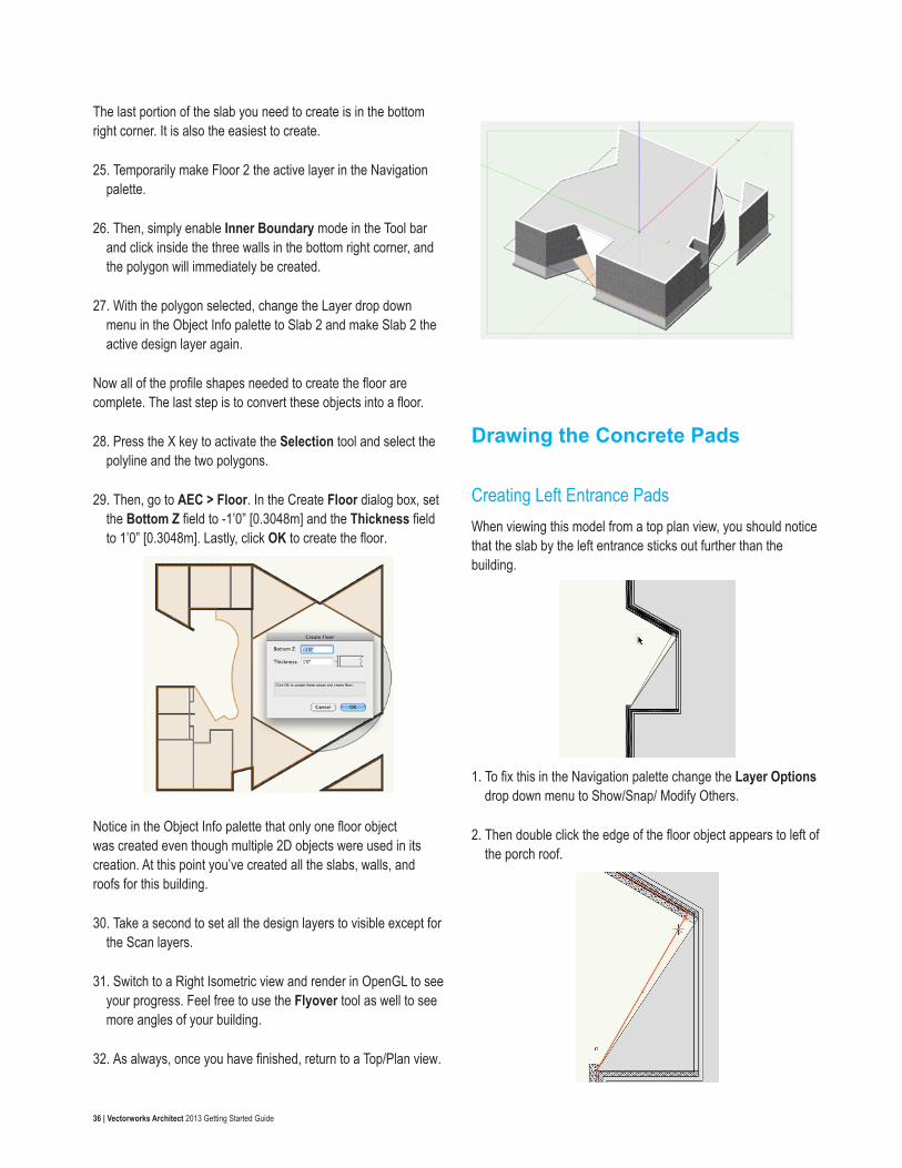
36 | Vectorworks Architect 2013 Getting Started Guide
The last portion of the slab you need to create is in the bottom right corner. It is also the easiest to create.
25. Temporarily make Floor 2 the active layer in the Navigation palette.
26. Then, simply enable Inner Boundary mode in the Tool bar and click inside the three walls in the bottom right corner, and the polygon will immediately be created.
27. With the polygon selected, change the Layer drop down menu in the Object Info palette to Slab 2 and make Slab 2 the active design layer again.
Now all of the profile shapes needed to create the floor are complete. The last step is to convert these objects into a floor.
28. Press the X key to activate the Selection tool and select the polyline and the two polygons.
29. Then, go to AEC > Floor. In the Create Floor dialog box, set the Bottom Z field to -1’0” [0.3048m] and the Thickness field to 1’0” [0.3048m]. Lastly, click OK to create the floor.
Notice in the Object Info palette that only one floor object was created even though multiple 2D objects were used in its creation. At this point you’ve created all the slabs, walls, and roofs for this building.
30. Take a second to set all the design layers to visible except for the Scan layers.
31. Switch to a Right Isometric view and render in OpenGL to see your progress. Feel free to use the Flyover tool as well to see more angles of your building.
32. As always, once you have finished, return to a Top/Plan view.
Drawing the Concrete Pads
Creating Left Entrance PadsWhen viewing this model from a top plan view, you should notice that the slab by the left entrance sticks out further than the building.
1. To fix this in the Navigation palette change the Layer Options drop down menu to Show/Snap/ Modify Others.
2. Then double click the edge of the floor object appears to left of the porch roof.

37 | Vectorworks Architect 2013 Getting Started Guide
This will take you the Edit Floor mode.
3. Select Reshape Tool from the Basic tool palette and make sure the first mode is enabled in the Tool bar.
4. Now click the vertex point shown in the screenshot below and move it to point shown in the screenshot below as well, which is the top most point of the porch roof.
5. Click to set this point. After moving the vertex point click Exit Floor.
Now, onto to the concrete pads.
In addition to creating the slabs for the interior of the building, you also need to take care of the concrete pads on the outside of the building. There should be one here toward the top of the drawing area, concrete steps on the left by this entrance, and another set of concrete steps by this porch entrance. We’ll begin with the first entrance area.
6. First, in the Navigation palette, set all design layers to invisible except Floor 1, Slab 1, and Scan 1.
7. Also, set Floor 1 as the active design layer in the Navigation palette and Choose Show/Snap Others from the Layer Options menu.
8. Additionally, make sure there are no objects selected and change the Fill color in the Attributes palette to a shade of gray. It’s okay if its the same shade of gray you used for the roofs.
9. Make sure you increase the Opacity in the Attributes palette back to 100% also too.
When there are no objects selected the settings shown in the Attributes palette are the default settings for any new objects to be drawn.
10. Now select the Wall tool from the Building Shell toolset’s palette and enable the first mode, Left Control mode.
11. Click Wall Preferences button in the Tool bar.
12. When the Wall Preferences dialog opens, select 6” Generic Wall from the Wall Style dropdown menu.
13. Under the Components section, click the New button and name the new component “Wood.”
14. Set the Thickness field to 4” [0.1016m]. Also choose Wall > Component > Struct from the Classes dropdown menu. Then click OK to return to the Wall Preferences dialog box.
15. Next, choose the Insertion Options tab and choose Layer Wall Height for the Top Bound dropdown menu.
16. Also choose Layer Elevation for the Bottom Bound dropdown menu.
17. In the top right corner, click the Save Preferences as Wall Style button and name this new wall style “Ext-Wood Frame-Window.” Click OK twice to return to the drawing area.
18. Now that your new wall style is created, click at the bottom point where the slab and the wall meet.

38 | Vectorworks Architect 2013 Getting Started Guide
19. Move your cursor upward and follow the edge of the slab. You should see the cursor cue “Parallel” appear as you move along the edge of the Floor object.
20. Once you reach the first wall, click when the cursor cue “Endpoint” is shown.
21. Turn on the Roof layer in the Navigation palette for a moment and render in OpenGL.
22. Now use the Flyover tool so that you are looking at the newly draw wall from the outside, you will see this wall does not align properly with this roof. Creating a sloped roof to match your wall can be done pretty simply:
23. Just select the wall and go to AEC > Fit Walls to Objects.
24. In the dialog box check the first option, Constrain Tops of Walls to 3D Geometry, and set the Fit to Objects on dropdown menu to Roof.
25. Also input 1” [0.0254m] in the Wall top embedding depth field.
Just as the names suggest, we want the top of the wall to adjust to match the geometry we have on the Roof layer, which in this case is the porch roof.
26. You don’t need to constrain the bottom of the wall, so click OK to fit the wall to the porch roof.
You should see the top of the wall is now sloped according to the slope of your porch roof. Later we’ll add windows to this wall.
27. You can now set the Roof design layer back to invisible and return to a Top/Plan view.
Now you can move on to creating the actual pads for the entrance steps.
28. Before you begin, be sure to change your active design layer to Slab 1 in the View bar.
29. Select the Line tool from the Basic tool palette.
30. Using Scan 1 as a reference, trace the left-most line of the steps to create a vertical line between these two walls. Remember that you can hold the Shift button to ensure you are drawing an accurate vertical line.

39 | Vectorworks Architect 2013 Getting Started Guide
31. Next, select the Polygon tool from the Basic tool palette and ensure that the second mode, Inner Boundary mode, is enabled.
32. Now click to the right of the line you just drew between the walls, and a polygon should be created to fill that area.
33. Next, choose the Offset tool from the Basic tool palette and enable the Offset by Distance and Duplicate and Offset modes in the Tool bar.
34. Additionally set the Distance field in the Tool bar to 6” [0.1524m].
35. Then click anywhere inside the polygon you just created, which should still be highlighted.
36. After the offset polygon is created, activate the Selection tool and drag the offset polygon by its right-most vertex point and snap it to the right-most vertex point of the larger polygon.
37. After moving the smaller polygon, again choose the Offset tool from the Basic tool palette and click anywhere inside the smaller polygon to create an even smaller offset.
38. Just as you did before, switch to the Selection tool. Then drag the newest offset by its right-most corner to the right-most corner of the larger polygon.
39. Set design layer Scan 1 to invisible from the Navigation palette.
There are your concrete steps. You just need to convert them into Floor objects, which we’ll do now.
40. With the Selection tool, select the largest polygon and go to AEC > Floor.
41. In the Create Floor dialog box, set the Bottom Z field to -18” [-0.4572m] since it is the lowest step and the Thickness field to 6” [0.1524m]. Click OK to create the floor object.
42. Then hold the B key on your keyboard and select the middle polygon.
Holding the B key enables X-ray Fills mode, which makes all 2D objects with a fill semi-transparent so that you can easily select any objects behind them.
43. Go back to AEC > Floor. This time set the Bottom Z field to -12” [-0.3048m]. The Thickness field should still be 6” [0.1524m]. Again click OK to create the floor.
44. Repeat these steps for the smallest polygon but set the Bottom Z field to -6” [-0.1524m].
The concrete pads for the entrance are complete.
Creating Porch Entrance and Topside Pads Let’s create the concrete pad and steps by the porch entrance next.

40 | Vectorworks Architect 2013 Getting Started Guide
1. Zoom to the bottom right portion of the building.
2. With the Line tool, click the left-most point of the larger triangular walls to set the first point of the line. Also click the bottom-most point of the smaller triangle to draw the line.
3. Next, with the Line tool still active, click the top-most point of the larger triangle.
4. Then hold the Shift key and move upward until you snap to the circular wall above.
5. When the cursor cue “Object/Vertical” appears, click to finish the line.
6. Now draw one more line. To start, click the left-most point of the larger triangle.
7. Hold the Shift key and move the cursor upward until you reach the circular wall again.
8. When the cursor cue “Vertical/Object” appears, click again to draw the line.
These lines will help define the boundaries for the two pads at this entrance.
9. Next select all three of these lines and change the Layer drop down menu in the Object Info palette to Floor 1.
10. Now temporarily make Floor 1 the active layer.
11. In the Basic tool palette, switch to the Polygon tool and enable the mode Inner Boundary in the Tool bar.
12. Click once inside each area blank. Two polygons should be created as shown in the screenshot.
13. Select the 2 newly created polygons.
14. Then go to Layer menu in the Object info palette and change it to Slab 1. Now make Slab 1 the active design layer again in the Navigation palette.
15. Tap the X key twice to deselect the all objects.
16. Then select the polygon below the circular wall, and go to Model > Extrude. Set the Extrusion field to 1’6” [0.4572m] and click OK.
17. Also go to the Object Info palette and set the Bot Z field to -1’6” [0.4572m].
This pad is actually a ramp, so there should be a slight slant to this extrude.
18. To create this slant, first switch to a Front view in the View bar.
19. Also in the View bar, set the Active Plane dropdown menu to Screen Plane.
20. Then, using the Polygon tool in Vertex mode, draw a triangle by clicking the following points—in this order—on the extrude: top left, bottom right, bottom left, and top left.
21. Now extrude this triangle by pressing Command + E (Macintosh) or Control + E (Windows).
22. When the Create Extrude dialog box appears, you can simply click OK without changing any of the parameters.
23. Change the view in the View bar to Left Isometric. The slant shown in this extrude needs to be applied to the extrude with the curve.

41 | Vectorworks Architect 2013 Getting Started Guide
24. Select the Push/Pull tool from the 3D Modeling toolset and enable the first mode in the Tool bar, Extrude Face mode.
25. Now, move your cursor to this face of the extrude until it is highlighted.
26. Click once on this same face of the extrude to select it.
27. Then move your cursor downward until the triangular extrude overlaps the other extrude.
28. Once you have pulled the extrude far enough, click again to resize the extrude.
29. Use the Selection tool, hold the Shift key and select both extrudes and go to Model > Intersect Solids. This will create one object with the desired angle for the two extrudes.
Now let’s finish the concrete pad to the left in front of the porch entrance.
30. Switch to a Top/Plan view.
31. Before you extrude the polygon, select the Rectangle tool from the Basic tool palette to draw the steps for this pad.
32. Also make sure the first mode is enabled in the Tool bar.
33. After activating the tool, click the bottom right corner of the polygon.
34. Then move your cursor to the left and snap to the inside corner of the bottom-most wall to create the rectangle.
35. With the rectangle still selected, press Command + D (Macintosh) or Control + D (Windows) to duplicate the rectangle.
36. Drag the duplicate rectangle by its bottom right corner and snap it to the top right corner of the original rectangle. These will be steps in the concrete pad.
37. Now, select the polygon and go to Model > Extrude.
38. In the Create Extrude dialog box, set the Extrusion field to 1’6” [0.4572m].
39. After, you create the extrude, change the Bot Z field in the Object Info palette to -18” [-0.4572m].
40. Next, select the bottom rectangle and extrude it 18” [0.4572m].
41. Then in the Object Info palette, set the Bot Z field to -12” [-0.3048m].
42. Choose the remaining rectangle and again extrude it 18” [0.4572m], but this time after you create the extrude, set the Bot Z field to -6” [0.1524m].
43. Last, select all three extrudes and go to Model > Subtract Solids.

42 | Vectorworks Architect 2013 Getting Started Guide
44. In the Select Object dialog box, click the arrows until the largest extrude is highlighted red. Then click OK to create the pad for the porch entrance.
It’s time to move on to the concrete pad on the topside of the drawing.
45. Zoom to the top portion of the drawing and select the Arc tool from the Basic tool palette.
46. Enable the second mode in the Tool bar, Three Points mode.
47. Now click where the round wall and the angled wall on the left meet.
48. For the next point, click anywhere along the top of the round wall.
49. Then hover your cursor over the bottom-most point of the triangular walls in the top right until a small red square appears to let you know you have acquired the Smart Point.
50. After acquiring the Smart Point, move your cursor back to downward until you reach the round wall.
51. When the cursor cue “Object/Align H” is displayed, click to set the third and final point for the arc.
Since you’ve created the arc shape for this pad, the rest of it can be drawn with the Polygon tool.
52. Select this tool from the Basic tool palette and enable the first mode.
53. The first vertex point should be the last point you set for the arc.
54. For the remaining points, set the vertex points at the same location in the same order as shown in the following screenshot.
55. Double-click on the last vertex point to complete the polygon.
56. Then switch to the Selection tool and hold the Shift key while selecting the arc you previously drew. Now both objects should be highlighted.
57. With both Objects selected, go to Modify > Compose to create one polyline from the two objects.
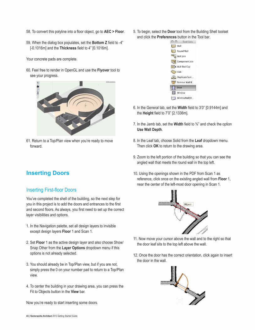
43 | Vectorworks Architect 2013 Getting Started Guide
58. To convert this polyline into a floor object, go to AEC > Floor.
59. When the dialog box populates, set the Bottom Z field to -4” [-0.1016m] and the Thickness field to 4” [0.1016m].
Your concrete pads are complete.
60. Feel free to render in OpenGL and use the Flyover tool to see your progress.
61. Return to a Top/Plan view when you’re ready to move forward.
Inserting Doors
Inserting First-floor DoorsYou’ve completed the shell of the building, so the next step for you in this project is to add the doors and entrances to the first and second floors. As always, you first need to set up the correct layer visibilities and options.
1. In the Navigation palette, set all design layers to invisible except design layers Floor 1 and Scan 1.
2. Set Floor 1 as the active design layer and also choose Show/Snap Other from the Layer Options dropdown menu if this options is not already selected.
3. You should already be in Top/Plan view, but if you are not, simply press the 0 on your number pad to return to a Top/Plan view.
4. To center the building in your drawing area, you can press the Fit to Objects button in the View bar.
Now you’re ready to start inserting some doors.
5. To begin, select the Door tool from the Building Shell toolset and click the Preferences button in the Tool bar.
6. In the General tab, set the Width field to 3’0” [0.9144m] and the Height field to 7’0” [2.1336m].
7. In the Jamb tab, set the Width field to ¾” and check the option Use Wall Depth.
8. In the Leaf tab, choose Solid from the Leaf dropdown menu. Then click OK to return to the drawing area.
9. Zoom to the left portion of the building so that you can see the angled wall that meets the round wall in the top left.
10. Using the openings shown in the PDF from Scan 1 as reference, click once on the existing angled wall from Floor 1, near the center of the left-most door opening in Scan 1.
11. Now move your cursor above the wall and to the right so that the door leaf sits to the top left above the wall.
12. Once the door has the correct orientation, click again to insert the door in the wall.

44 | Vectorworks Architect 2013 Getting Started Guide
Let’s do this again with the opening shown to the right of the door you’ve just inserted.
13. With the Door tool still active, click at the center of the opening and position the door leaf to the top right.
14. Then click once more to insert the door. Notice this second door was placed with the exact same door settings as the first door.
Any new doors placed in this file will also have these parameters until you go back to the Door Settings and change them. There are still several more doors using the exact same settings as the first two.
15. Use the following screenshots as a reference and insert the doors in your file at the same locations. Don’t forget to set your doors’ flip correctly before inserting them.
Now you’ll need to change the door settings to place a different type of door in this wall.
16. The Door tool should still be active, so click the Preferences
button in the Tool bar and in the General tab set the Width field to 6’0” [1.8288m].
17. Also change the Configuration dropdown menu to Swing Bi-part. Then click OK to return to drawing, and place the door at the current opening shown in Scan 1.
18. Also, make sure the door is flipped so the swings are inside the room.
After placing this door, you will again need to access the Door tool Preferences from the Tool bar so that you can modify the parameters once more to place a third type of door on the first floor.
19. This time when the dialog box appears, in the General tab, change the Width field to 5’0” [1.524m] and the Configuration dropdown menu to Slider.
20. Additionally, set the Open Angle field in the 3D Visualization tab to 45 and click OK to return to the drawing area.
21. With the Zoom tool or the scroll wheel on your mouse, zoom to the room to the left of the stairs in the bottom left portion of the building.
22. Next, with the Door tool, click at the midpoint of the wall in the below screenshot and set the flip so that the slider opening is at the bottom.
23. Now place 2 more doors in this wall with the same orientation, and don’t forget to snap to the wall’s midpoint before inserting the door.
Now all of the doors for the first floor are complete.

45 | Vectorworks Architect 2013 Getting Started Guide
Inserting Second-Floor Doors1. Before you can begin inserting the second-floor doors, you will
need to set design layers Floor 1 and Scan 1 to invisible and design layers Floor 2 and Scan 2 to visible.
2. Additionally, make Floor 2 the active layer.
As you would expect, the same type of doors from the first floor will also be used on the second floor. So instead of resetting the parameters in the Door Settings, we can use the Create Similar Objects command to place a door with the exact same settings as the doors already in your file.
3. To do this, let’s temporarily make Floor 1 the active layer again.
4. Then right-click on the door found in the bottom right corner of the building and select Create Similar Object.
Notice the Door tool is still active, but the door preview has changed to that of the door you just clicked.
5. Now you can make Floor 2 the active design layer again and begin inserting the doors at the same locations as shown in the following screenshot.
Again, don’t forget to use the opening shown in Scan 2 as a reference. Also remember that the flip for the doors in your file should match that of the doors shown in the screenshots. Here’s what you should have when you’re done. That’s it for the doors.
6. You can now render in OpenGL and take a look at your progress with the Flyover tool.
7. Then return to a Top/Plan view when you are ready to move forward.
Inserting Windows
Inserting Second-floor WindowsJust as you did when inserting the doors in the previous exercise, you’ll use the openings shown in the PDF from Scan 2 to place your windows at the correct location. Before inserting these windows, we need to configure the windows according in the Windows settings.
1. To start, select the Window tool from the Building Shell toolset and click the Preferences button in the Tool bar.
2. In the General tab, set the Width field to 10’8” [3.2512m], the Height field to 4’0” [1.2192m], and the Elevation in Wall field to 96” [2.4384m].
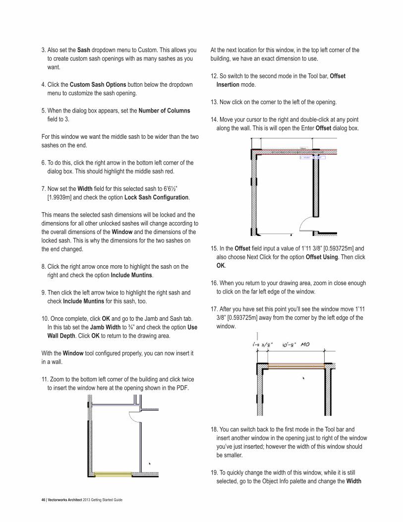
46 | Vectorworks Architect 2013 Getting Started Guide
3. Also set the Sash dropdown menu to Custom. This allows you to create custom sash openings with as many sashes as you want.
4. Click the Custom Sash Options button below the dropdown menu to customize the sash opening.
5. When the dialog box appears, set the Number of Columns field to 3.
For this window we want the middle sash to be wider than the two sashes on the end.
6. To do this, click the right arrow in the bottom left corner of the dialog box. This should highlight the middle sash red.
7. Now set the Width field for this selected sash to 6’6½” [1.9939m] and check the option Lock Sash Configuration.
This means the selected sash dimensions will be locked and the dimensions for all other unlocked sashes will change according to the overall dimensions of the Window and the dimensions of the locked sash. This is why the dimensions for the two sashes on the end changed.
8. Click the right arrow once more to highlight the sash on the right and check the option Include Muntins.
9. Then click the left arrow twice to highlight the right sash and check Include Muntins for this sash, too.
10. Once complete, click OK and go to the Jamb and Sash tab. In this tab set the Jamb Width to ¾” and check the option Use Wall Depth. Click OK to return to the drawing area.
With the Window tool configured properly, you can now insert it in a wall.
11. Zoom to the bottom left corner of the building and click twice to insert the window here at the opening shown in the PDF.
At the next location for this window, in the top left corner of the building, we have an exact dimension to use.
12. So switch to the second mode in the Tool bar, Offset Insertion mode.
13. Now click on the corner to the left of the opening.
14. Move your cursor to the right and double-click at any point along the wall. This is will open the Enter Offset dialog box.
15. In the Offset field input a value of 1’11 3/8” [0.593725m] and also choose Next Click for the option Offset Using. Then click OK.
16. When you return to your drawing area, zoom in close enough to click on the far left edge of the window.
17. After you have set this point you’ll see the window move 1’11 3/8” [0.593725m] away from the corner by the left edge of the window.
18. You can switch back to the first mode in the Tool bar and insert another window in the opening just to right of the window you’ve just inserted; however the width of this window should be smaller.
19. To quickly change the width of this window, while it is still selected, go to the Object Info palette and change the Width

47 | Vectorworks Architect 2013 Getting Started Guide
25. There’s one more of these small casement windows located toward the top left of the building. Place another one here.
Now you are finished with this particular type of window.
Next, you need to configure another custom sash window.
26. Again with the Window tool still active, click the Preferences button in the Tool bar.
27. In the General tab set the Width field to 6’0” [1.8288m], the Height field to 8’7” [2.6162m], the Elevation in Wall field to 0” [0m], and also choose Sill of Window for the Elevation Reference.
28. Additionally choose Custom Sash from the Sash drop-down menu. Then click the Custom Sash Options button.
29. When the dialog box appears set the Number of Rows field to 2 and the Number of Columns field to 1.
30. Click OK twice to return to the drawing area and click twice at the shown opening to insert the window.
You’re almost done with the windows for this floor. There are just
field from 10’8” [3.2512m] to 8’8” [2.6416m] and press the Enter key to lock in the value.
You need to insert a few more windows with this same width of 8’8” [2.6416m], so again we can use the Create Similar Objects command.
20. This time, instead of right-clicking on the window, hold the Command + Option keys (Macintosh) or Control + Alt keys (Windows). Notice the cursor changes to an eyedropper.
21. Click on the last window you inserted. Now the Window tool will use the same parameters set with this specific window.
22. You can now continue and insert a window in these two openings near the bottom left of the building.
23. For the smaller window located below the windows you just placed, go back to the Window Preferences in the Tool bar.
24. Then in the General tab, set the Width field to 4’0” [1.2192m] and change the Sash drop-down menu to Casement. Click OK to return to the drawing area and insert the window based on the opening shown in the PDF on design layer Scan 2.

48 | Vectorworks Architect 2013 Getting Started Guide
a few fixed glass windows to be inserted in the walls on the right side of the building.
31. To create this window, select the Window tool and click the Preferences button in the Tool bar.
32. In the Window settings from the General tab, set the Sash dropdown to Fixed Glass.
33. Also set the Width to 15’0” [4.572m], the Height to 5’0” [1.524m], the Elevation in Wall to 4’0” [1.2192m], and the Elevation Reference to Sill of Window. Then click OK to return to the drawing area.
34. Just as you did before, place your window at the same location as shown in the following screenshot and use the PDF scan as a reference for the best placement for the window.
35. After inserting this window, go back to the Window Preferences and change the Width field to 25’0” [7.62m], the Height field to 8’0” [2.4384m], the Elevation in Wall field to 1’0” [0.3048m], and the Elevation Reference to Sill of Window.
36. Once you click OK, place a window at the two openings shown in the screenshot.
Creating a Custom Window SymbolSo far, you’ve only created windows using the Window tool, but sometimes when you have a uniquely shaped window you will need to create it from scratch and create a symbol to be inserted in the wall. This is the case for the next type of window you will be creating.
1. First, select this wall.
2. Then, in the Navigation palette, set the Roof layer to visible.
3. Also switch to a Back view from the View bar and zoom in on the highlighted wall.
4. You will be creating a triangular shaped window in this wall, so select the Polygon tool from the Basic tool palette and make sure Vertex mode is enabled.
5. Now click at the same three points as shown in the following screenshot. Click at your start point after placing these points to close the shape. Don’t forget to use the Snap Loupe to temporarily zoom in for a better view.

49 | Vectorworks Architect 2013 Getting Started Guide
6. Once the triangle is completed, select the Offset tool from the Basic tool palette and enable modes Offset by Distance and Offset Original Object from the Tool bar.
7. Also in the Tool bar set the Distance field to 1’0” [0.3048m].
8. After that click inside the existing triangle to create a smaller offset of the original.
9. Again return to the Tool bar and enable Offset and Duplicate mode and change the Distance field to 2” [0.6096m].
10. Then click inside the existing triangle once again. A smaller duplicate will be created inside the current triangle.
11. Next, press the X key to switch to the Selection tool and select both triangles.
12. Right-click one of the selected triangles and choose Clip Surface from the Context menu.
Normally you would delete the smaller object that has been clipped, but in this case we keep it, as this will be the glass portion of the window.
13. Now, select the larger polyline and go to Model > Extrude.
14. When the Create Extrude dialog box appears, set the Extrusion field to 11 5/8” [0.295275m] and click OK to create the Extrude.
15. Now, select the smaller triangle and go to Model > Extrude. This time, set the Extrusion field to .125” [0.295275m], and click OK.
16. While this second extrude is still selected, go to the Render tab in the Object Info palette.
17. Locate the Texture dropdown menu and choose Glass Clear.
Now that you have both the frame and glass for your window, let’s create a symbol from these two extrudes and insert it into the wall properly.
18. While holding the Shift key, select both the smaller triangle and the larger polyline. Then, go to Modify > Create Symbol.
19. In the Create Symbol dialog box name the symbol “Triangular Window.”
20. Also make sure the option Insert in Walls is checked along with Leave Instance In-Place.
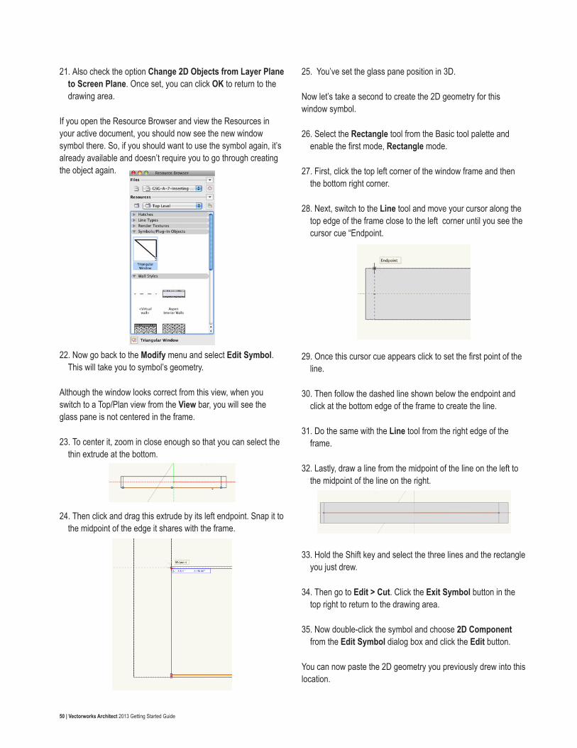
50 | Vectorworks Architect 2013 Getting Started Guide
21. Also check the option Change 2D Objects from Layer Plane to Screen Plane. Once set, you can click OK to return to the drawing area.
If you open the Resource Browser and view the Resources in your active document, you should now see the new window symbol there. So, if you should want to use the symbol again, it’s already available and doesn’t require you to go through creating the object again.
22. Now go back to the Modify menu and select Edit Symbol. This will take you to symbol’s geometry.
Although the window looks correct from this view, when you switch to a Top/Plan view from the View bar, you will see the glass pane is not centered in the frame.
23. To center it, zoom in close enough so that you can select the thin extrude at the bottom.
24. Then click and drag this extrude by its left endpoint. Snap it to the midpoint of the edge it shares with the frame.
25. You’ve set the glass pane position in 3D.
Now let’s take a second to create the 2D geometry for this window symbol.
26. Select the Rectangle tool from the Basic tool palette and enable the first mode, Rectangle mode.
27. First, click the top left corner of the window frame and then the bottom right corner.
28. Next, switch to the Line tool and move your cursor along the top edge of the frame close to the left corner until you see the cursor cue “Endpoint.
29. Once this cursor cue appears click to set the first point of the line.
30. Then follow the dashed line shown below the endpoint and click at the bottom edge of the frame to create the line.
31. Do the same with the Line tool from the right edge of the frame.
32. Lastly, draw a line from the midpoint of the line on the left to the midpoint of the line on the right.
33. Hold the Shift key and select the three lines and the rectangle you just drew.
34. Then go to Edit > Cut. Click the Exit Symbol button in the top right to return to the drawing area.
35. Now double-click the symbol and choose 2D Component from the Edit Symbol dialog box and click the Edit button.
You can now paste the 2D geometry you previously drew into this location.

51 | Vectorworks Architect 2013 Getting Started Guide
36. Go to Edit > Paste in Place.
37. Additionally, go to the Shape tab in the Object Info palette and verify the Plane dropdown menu is set to Screen.
38. After verifying, once again click the Exit Symbol button in the top right, which should still be displaying a Back view.
39. Again, choose Top/Plan from the Standard View menu in the View bar. Also set the Roof layer back to invisible.
40. After changing views, you can see the window is not in the correct location.
41. To insert the window into the wall, simply click and drag it from its current location and release the symbol once the wall is highlighted. Don’t forget to use the PDF scan as a reference for the best placement.
The windows for this floor are now complete.
42. Take a second to render in OpenGL and use the Flyover tool to see your results.
43. Then return to a Top/Plan view when you’re finished.
Creating a Circular Window on the First-FloorThe process for creating a circular window will be exactly like creating the triangular window except, of course, with a different shape. This time we can move through the steps a little more quickly.
1. Before you begin, in the Navigation palette set design layers Floor 2 and Scan 2 to invisible and design layers Floor 1 and Scan 1 to visible.
2. Also switch to a Left view from the Standard View menu in the View bar.
3. You’ll want to create the geometry for this window off to the right of the building, so with the Pan tool press and hold the mouse near the center of the drawing area and then drag to the left.
4. Release the mouse button once a majority of the building is off the screen.
5. Then select the Circle tool from the Basic tool palette and enable the second mode, Diameter mode.
6. Now click anywhere in the drawing area to start the circle.
7. After setting the first point, press the Tab key to enter the Length field in the Floating Data bar. Input 48” [1.2192m] and press Enter to lock in the value.
8. Next, hold the Shift key and move your cursor above the first point you set. Then click once to create the circle.
9. Switch to the Offset tool in the Basic tool palette and enable modes Offset by Distance and Offset and Duplicate.
10. In the Distance field located in the Tool bar, enter a value of 4” [0.1016m]. Then click inside the current circle to create the duplicate.

52 | Vectorworks Architect 2013 Getting Started Guide
11. The duplicate circle will still be highlighted so switch to the Selection tool, hold the Shift key and select the larger circle as well.
12. Once both circles are highlighted, go to Modify > Clip Surface.
Just as with the triangular window, you will not be deleting the smaller circle, as this will be the glass portion of the window.
13. With the smaller circle still selected, you can now go to Model > Extrude and set the Extrusion field to .125” [0.295275m]. Click OK to convert the circle to an extrude.
14. With the extrude still selected, go to the Render tab and set the Texture drop down menu to Glass as you did last time.
15. Now, select the larger polygon, which will be the window frame and go back to Model > Extrude. This time the Extrusion field should be set to 11’ 5/8” [3.36868m]. Again, click OK to create the extrude.
So that you don’t have to go back into the symbol after its creation, let’s move the smaller extrude to sit in the middle of the circular frame.
16. To do this, switch to a Front view from the View bar.
17. Click the Fit To Objects button if the circular extrudes have moved off screen.
You could click and drag the smaller extrude to the middle of the larger one as you did in the previous video, but let’s try a different approach this time.
18. Select both extrudes and to go Modify > Align > Align/Distribute 3D.
19. When the dialog box appears, choose Active Layer Plane X Y Z.
20. In the X section check the Align option and choose Center. Once the parameters are set properly, click OK and you will see the two extrudes as aligned horizontally by their center points.
21. After you’ve centered the extrude, you can go a Top/Plan view. Again you may need to click the Fit To Objects button in the View bar to locate the extrudes.
22. Before making a symbol, you need to rotate the extrude so it sits horizontally. So, with both extrudes selected, go to Modify > Rotate > Rotate Left 90°.
23. You can now go to Modify > Create Symbol. In the Create Symbol dialog box, name the symbol “Circular Window,” uncheck Leave Instance In-Place and click OK.
If you open the Resource Browser, you will see it now appears in the symbols section along with your previously created window symbol.
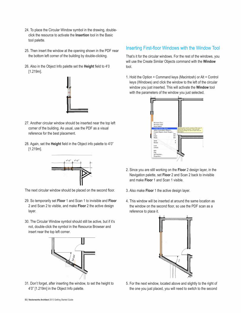
53 | Vectorworks Architect 2013 Getting Started Guide
24. To place the Circular Window symbol in the drawing, double-click the resource to activate the Insertion tool in the Basic tool palette.
25. Then insert the window at the opening shown in the PDF near the bottom left corner of the building by double-clicking.
26. Also in the Object Info palette set the Height field to 4’0 [1.219m].
27. Another circular window should be inserted near the top left corner of the building. As usual, use the PDF as a visual reference for the best placement.
28. Again, set the Height field in the Object info palette to 4’0” [1.219m].
The next circular window should be placed on the second floor.
29. So temporarily set Floor 1 and Scan 1 to invisible and Floor 2 and Scan 2 to visible, and make Floor 2 the active design layer.
30. The Circular Window symbol should still be active, but if it’s not, double-click the symbol in the Resource Browser and insert near the top left corner.
31. Don’t forget, after inserting the window, to set the height to 4’0” [1.219m] in the Object Info palette.
Inserting First-floor Windows with the Window ToolThat’s it for the circular windows. For the rest of the windows, you will use the Create Similar Objects command with the Window tool.
1. Hold the Option + Command keys (Macintosh) or Alt + Control keys (Windows) and click the window to the left of the circular window you just inserted. This will activate the Window tool with the parameters of the window you just selected.
2. Since you are still working on the Floor 2 design layer, in the Navigation palette, set Floor 2 and Scan 2 back to invisible and make Floor 1 and Scan 1 visible.
3. Also make Floor 1 the active design layer.
4. This window will be inserted at around the same location as the window on the second floor, so use the PDF scan as a reference to place it.
5. For the next window, located above and slightly to the right of the one you just placed, you will need to switch to the second

54 | Vectorworks Architect 2013 Getting Started Guide
mode in the Tool bar, Offset Insertion mode.
6. Then click on the corner to the left of the opening.
7. Move your cursor to the right and double-click on any point along the wall. This is will open the Enter Offset dialog box.
8. In the Offset field input a value of 1’11 3/8” [0.593725m], and choose Next Click for the option Offset Using. Then click OK.
9. When you return to your drawing area, zoom in close enough to click on the far left edge of the window.
After you have set this point you’ll see the window move 1’11 3/8” [0.593725m] away from the corner by the left edge of the window.
You’re almost done with the windows and doors for the building. In the following videos, you will learn to create custom window walls for the entrances. So now is a good time to stop and render in OpenGL and take a look at your progress with the Flyover tool.
At this point you should notice the circular windows are sitting high above the actual walls.
10. To fix this, double-click one of the circular window symbols, which will take you to the symbol edit mode.
11. Then switch to front view from the View bar or by pressing the
2 key on your number pad.
Notice the extrude objects are above the origin 0,0. This is why they appear above the walls in the model.
12. Now, select the two extrude objects if they are not already selected. Then go to Modify > Move > Move 3D.
13. When the dialog box appears, set the Z Offset field to -17’1 and click OK.
14. You should see the extrudes are centered on the origin point now. You can click Exit Symbol in the top right corner.
15. Now lets render in OpenGL and take a look at the model using the Flyover tool.
There. Now the circular windows are in the correct location.
16. When you’re done, return to a Top/Plan view.

55 | Vectorworks Architect 2013 Getting Started Guide
Creating the Building Entrances
Creating the Front Porch EntranceAt this point you’ve created and placed the majority of the doors and windows for this building. There are just two more areas where doors and windows need to be inserted with the Door and Window tools: the front porch entrance and the back porch entrance. You’ll start with the front porch area.
The design layers Floor 1 and Scan 1 should still be the only visible layers. If you need to make this change in your file, do so now.
First, you’ll need to configure the first window to be inserted in this wall.
1. To do this, select the Window tool from the Building Shell toolset and click the Preferences button in the Tool bar.
2. In the Window Settings go to the General tab and input 6’0” [1.829m] in the Width field, 8’7” [2.6162m] in the Height field, and 2’1”[0.635m] in the Elevation in Wall field.
3. Set the Elevation Reference dropdown menu to Sill of Window.
4. Additionally, set the Sash dropdown menu to Custom. Then click the Custom Sash Options button below.
5. In the Custom Sash Options dialog box, the set the Number of Rows to 2 and the Number of Columns to 1.
Currently, the top sash should be highlighted red—if it is not press, the left or right selection arrows in the bottom left until it is highlighted.
6. Once highlighted in the Selected Sash field, set the Width field to 5’10 ½” [1.7907m], the Height field to 4’2” [1.27m], and the Operation dropdown menu to Fixed Glass.
7. Press the right arrow to highlight the bottom sash and verify that the Operation dropdown menu is set to Fixed Glass.
Then, click OK twice to return to the drawing area.
Now you need to insert the Window 7” [0.1778m] from the left end of the wall.
8. To do this, enable the second mode for the Window tool, Offset Insertion mode.
9. Next, click the left edge of this wall.
10. Then move your cursor to the right and double-click at any point along the wall. This will open the Enter Offset dialog box.
11. In the Offset field, input a value of 7” [0.1778m], and under the Offset Using option, choose Next Click. Then click OK.
12. When you return to your drawing area, zoom in close enough to click on the far left edge of the window.
After you have set this point, you’ll see the window move 7” [0.1778m] away from the corner by the left edge of the window.
13. Moving on to the next window, you will need to return to the

56 | Vectorworks Architect 2013 Getting Started Guide
Window Settings to configure it, so click the Preferences button in the Tool bar.
14. For this window, use a Casement sash. Also set the Width field to 36” [0.9144m], the Height field to 7’0” [2.1336m], and the Elevation in Wall field to 1”. Click OK to return to the drawing area.
The second mode, Offset Insertion, should still be enabled, but this time this window should be offset 9” [0.2286m] from the right edge of the window you previously inserted.
15. To do this, click the right edge of the existing window.
16. Then move your cursor to the right and double-click at any point along the wall.
17. When the Enter Offset dialog box appears, input a value of 9” [0.2286m] in the Offset field and choose Insertion Point for the option Offset Using. Then click OK.
18. When you return to your drawing area, zoom in close enough to click on the far left edge of the window.
After you have set this point, you’ll see the window move 9” [0.2286m] away from the first window.
Now it’s time to insert some doors.
19. Select the Door tool from the Building Shell toolset and click the Preferences button in the Tool bar.
20. In the General tab of the Door Settings, the Width field should be set to 3’0” [0.9144m], the Height field should be set to 7’0” [2.1336m], and the Configuration should be Simple Swing.
21. In the Jamb tab set the Width field to ¾” [0.01905m] and check the option Use Wall Depth.
22. Next, go the Leaf tab and choose Glass from the Panel dropdown menu. Then set the Top Rail Width to 4” [0.1016m] and the L/R Stile Width to 4” [0.1016m]. Click OK to return to the drawing area.
This door needs to be 3” [0.0762m] away from the last window you inserted in the wall.
23. So enable the second mode, Offset Insertion mode, in the Tool bar, and click on the right edge of the last window you inserted.
24. Move your cursor to the right and click once anywhere along the wall.
25. Now move your cursor until the door’s leaf sits below the wall and to the left. Then click again.
26. When the Enter Offset dialog box appears, input a value of 3” [0.0762m] for the Offset field and choose Next Click for the option Offset Using. Then click OK.
27. When you return to your drawing area, zoom in close enough to click on the far left edge of the door you just inserted.
After you have set this point, you’ll see the door move 3” [0.0762m] away from the window.
28. Two more doors with the same parameters must be inserted in this wall, so repeat this process to insert two more doors that are three inches apart to the right of the current door.

57 | Vectorworks Architect 2013 Getting Started Guide
To the right of these three doors are two more casement windows with the same settings as the one that sits to the left of the three doors in the wall.
29. You can right-click this window and choose Create Similar Object to activate the Window tool with the exact same parameters as the selected window.
30. Now make sure you are in the second mode, Offset Insertion mode in the Tool bar, and insert two more windows in the wall—one that is 3” [0.0762m] from the last door and one that is 3” [0.0762m] from the next window.
That’s it for the front porch entrance.
31. Switch to Right Isometric view from the View bar and render in OpenGL to see what the new entrance looks like.
If you take a look at the left end of this entrance, you will notice that the highlighted wall currently blocks the view from the far left window. To fix this, you need to shape the wall slightly.
32. First, switch to the Reshape tool in the Basic tool palette, select the same wall in your file as in the above screenshot, and enable the second mode in the Tool bar, Add 3D Wall Peaks.
33. Then click the top right vertex point of the wall.
34. Move your cursor to the left until you snap to the perpendicular wall.
35. When the cursor cue Angle appears, click once more to add the new vertex point to the wall.
36. Now enable the first mode in the Tool bar, Reshape 3D Walls, and select the vertex point at the top right corner of the wall.
37. Once the vertex point is selected, press the Tab key twice to enter the Top field in the Floating Data bar. Input 48” [1.2192m] and press Enter to lock in the value.
38. Now click once more to move the vertex point.

58 | Vectorworks Architect 2013 Getting Started Guide
39. You need to add another point to this wall, so again enable Add 3D Wall Peaks in the Tool bar and click the vertex point you just moved.
40. Hold the Shift key and move your cursor to the left until you reach the perpendicular wall. Then click to add the new vertex point.
Now this wall no longer blocks the large window in the wall behind it. If you like. You can take a look at your progress with the Flyover tool. Once you are finished, return to a Top/Plan view so we can make the back porch entrance.
Creating the Back Porch EntranceTo create the back porch entrance you’ll again need to start by inserting a window. However, instead of offsetting the window from the wall’s edge, you need to offset from the middle of the wall. So let’s mark the wall’s midpoint.
1. To do this, select the Line tool in the Basic tool palette. Snap to the wall’s midpoint and click once the cursor cue “Midpoint” appears.
2. Hold the Shift key, move your cursor to the right, and click once the cursor cue “Perpendicular” is displayed. It doesn’t matter what length the line is, as it is just a reference that will be deleted later.
3. Now you can select the Window tool from the Building Shell toolset and click the Preferences button in the Tool bar.
4. In the Window Settings dialog box, go to the General tab and choose Casement for the Sash if it is not already selected.
5. Also set the Width field to 3’10” [1.1684m], the Height field to 7’0” [2.1336m], and the Elevation in Wall field to 0” [0m].
6. Next switch to the Jamb and Sash tab, set the Jamb Width to ¾” and check the option Use Wall Depth. Then click OK to return to the drawing area.
7. Make sure Offset Insertion mode is enabled in the Tool bar and click the midpoint of the wall you marked earlier with the Line tool.
8. Then move your cursor to the right and double-click at any point along the wall.
9. When the Enter Offset dialog box appears, input a value of 2” [0.0508m] in the Offset field and choose Next Click for the option Offset Using. Then click OK.
10. When you return to your drawing area, zoom in close enough to click on the far left edge of the window.
After you have set this point, you’ll see the window move 2” [0.0508m] away from the midpoint.
OK now you need to insert two more windows with the same

59 | Vectorworks Architect 2013 Getting Started Guide
settings into this wall. Last time, you used the Offset Insertion mode twice. This time we’ll use the Move by Points tool once.
11. Select the Move by Points tool from the Basic tool palette and enable Move mode and Object Retention mode in the Tool bar.
12. Additionally, set the Number of Duplicates field to 2.
13. Next, with the previously inserted window selected, click the left edge of the window.
14. Then press the Tab key to enter the Length field in the Floating Data bar. Input a value of 4’2” [1.27m] and press Enter to lock in the value.
15. Then click once more to create the duplicate windows. Now you have half of the windows inserted.
The windows on the other half of the wall are exactly the same, so you can use the Mirror tool to duplicate windows.
16. First, hold the Shift key and select all three windows in the wall.
17. Then activate the Mirror tool in the Basic tool palette and make sure Duplicate mode is enabled in the Tool bar.
18. Now click both endpoints of the line that is perpendicular to the wall. This will create the mirror axis line, and you will see three additional windows created on the other half of the wall.
19. Use the Flyover tool in the Basic tool palette to take a look at this wall in 3D.
Right now, there is just one row of windows on the bottom. Next, you will create the top row of windows, which will be sloped to match the wall.
20. To begin, select the leftmost window. In the Object Info palette change the Elevation field to 7’4” [2.2352m], the Height field to 10’4” [3.1496m], the Top Shape menu to Sloped, and the Rise field 1’8 3/8” [0.517525m].
21. To create the rest of the sloped windows in this row, select the previously created sloped window and go to Edit > Duplicate

60 | Vectorworks Architect 2013 Getting Started Guide
Array.
22. In the Duplicate Array dialog box, set Number of Duplicates to 5 and Offset Between Duplicates to 4’2” [1.27m]. Also click the direction button until so that the arrow in the preview points to the bottom left.
23. Then click OK to create the rest of the windows for the top row.
As you can see, all of the duplicates are currently too tall for the wall. To resolve this, you will need to change the height field in the Object Info palette for each window separately.
24. The height of the second window from the left in the row should be changed in the Object Info palette to 8’6” [2.5908m].
25. The third window from the left should be 6’8” [2.032m].
26. The fourth from the left should be 4’10” [1.4732m], the fifth should be 3’0” [0.9144m], and the last should be 1’3” [0.381m].
There is one last open portion in this wall for a door since it is the entrance from the back porch area.
27. To place the door, first go to the Door tool, enable the first mode, and click the Preferences button in the Tool bar.
28. When the Door Settings dialog box opens, it should have the same parameters as the doors used for the Front porch. Therefore, you should only need to change a few settings.
29. Go to the Leaf tab and change the Bottom Rail Width to 6” [0.1524m]. If this value is not already set. Then click OK to return to the drawing area.
30. Switch to a Top/Plan view from the View bar and click at the midpoint of the right-most window.
31. Move your cursor until the door leaf is below the wall and to the right. Click once more to create the door.
32. After the door is placed in the wall, drag the door by its left edge and snap it to the left edge of the same window.
Now both entrances are complete.
33. Take a look in OpenGL with the Flyover tool before you move forward.
34. When you are ready to move forward, return to a Top/Plan view.

61 | Vectorworks Architect 2013 Getting Started Guide
Adding Stairs and Handrails
Creating Straight StairsThere are only two stairs in this building: one straight staircase and one platform staircase, which you will create using two small straight stairs and a floor object. Since this is only a two-story building, there are no stairs on the second floor, but you will need to create a couple of handrails for the balcony area on that floor. Let’s begin with the simpler straight stair.
1. First, with no objects selected change the Fill color in the Attributes palette back to white.
1. Then, make sure you have only the design layers Floor 1 and Slab 2 visible in the Navigation palette. Floor 1 should also be the active layer.
2. Once your design layers are set correctly, select the Stair tool from the Building Shell toolset, and click the Preferences button in the Tool bar.
3. In the General tab under General Geometry, set the values in your dialog box to match the settings shown in the screenshot. The ones highlighted have been changed from the default values.
4. Now go to the Geometry tab, where you will find more specific options for the stair’s geometry. Again, set your values to match the ones shown here. The ones that have been changed from their default values are highlighted.
5. Now go the 2D Graphics tab to customize the stairs’ appearance in a Top/Plan or 2D view. Just as with the other two tabs, you should adjust the settings in your dialog to match the ones shown here.
6. Moving on to the Construction tab, you can choose a construction style along with applicable parameters for each

62 | Vectorworks Architect 2013 Getting Started Guide
construction style. Change the parameters to match those shown in the following screenshot.
7. Lastly, go to the Railings tab to configure the settings for the Left and Right handrails of the Stairs. Again set your parameters to match what’s shown below.
Although you don’t need to use them all right now, notice that each section has an expandable list of options that can be configured for your handrail.
8. Once you’re finished configuring the stair settings, click OK to
return to the drawing area.
9. To place the stair, snap to this midpoint on the second-floor slab. Then move your cursor to the left when the cursor cue 30° appears click to set the stairs.
10. As you can see, the stair overlaps this wall some. So switch to the Selection tool.
11. Move the stair by its bottom left point and snap to the wall’s endpoint. This will move the stair back a bit to its correct location.
With the stair positioned properly, we now need to slope the adjacent wall to match the stair .
12. With the Selection tool, select the highlighted wall from the above screenshot and switch to a Rear Right Isometric view from the View bar.
13. Additionally, in the View bar choose OpenGL from the

63 | Vectorworks Architect 2013 Getting Started Guide
Render dropdown menu.
14. Also turn off design layer Slab 2 from the Navigation palette.
15. With the wall still selected, switch to the Reshape tool in the Basic tool palette and enable the first mode, Reshape 3D Walls, in the Tool bar.
16. Select the top right vertex point and move it to the bottom right corner of the wall to create a slope that matches the stair. After you’ve sloped the wall, the straight stair is complete.
17. Before moving forward, return to a Top/Plan view and set design layer Slab 2 back to visible.
Creating a Winder Stair1. You can now move to the top left area of the building to place
the platform stair here.
2. In the Building Shell toolset, again select the Stair tool and click the Preferences button in the Tool bar.
3. Go to the General tab and set your values to match those shown here.
4. Then do the same for the Geometry tab.
5. Also change the highlighted parameters for the 2D Graphics tab.

64 | Vectorworks Architect 2013 Getting Started Guide
6. Also copy the setting shown for the Railings tab.
7. Click OK to return to the drawing area once you have configured the stair properly.
8. Now click anywhere in this area then rotate the stair so that the direction arrow points to the top left corner of the drawing area.
9. Click again once the cursor cue 30.00° is displayed.
This is not the correct location for the stair, but this will ensure you stair sits at the same angle as the wall.
10. To move the stair to its correct location, switch to the Selection tool in the Basic tool palette.
11. With the stair still selected, move it by its left midpoint to approximately the midpoint of the wall.
12. You might notice the stair angle is not kind the same angle as the adjacent wall. To fix this, with the stair still selected, change the Rotation field in the Object Info palette to 60.65°.
13. Then move the stair if necessary by its edge again so that it snaps to the face of the wall.
These will be the stairs below the platform.
14. To make the stairs that will be above the platform go back to the Stair tool and click the Preferences button once more.
Most of the same settings from the last stair will be used, but since this one will be a shorter staircase, there are still a few parameters that need to be changed.
15. Modify the settings in your dialog box to match the ones shown in the General tab and click OK to return to the drawing area.

65 | Vectorworks Architect 2013 Getting Started Guide
16. Now click once anywhere above the existing stairs.
17. Then hold the Shift key and move your cursor downward until the cursor cue “Vertical” appears. Click again to place the stair in the drawing.
18. After the stairs orientation is set, move the stair by its top right corner and snap it to this corner of the slab.
Remember this portion of the stair is supposed to be above the platform, so go to the Object Info palette and change the Z field to 6’0” [1.8288m].
The platform, which will be a floor object, is the last part of the stair that we need to create. Just as we did earlier in this project, we will first draw the floor’s 2D geometry and then convert that geometry into a floor.
19. Select the Polygon tool from the Basic tool palette and enable the first mode, Vertex mode.
20. Once the tool is active, click the bottom left corner of the vertical stairs.
21. Next, snap to the closest corner of the angled stair. Hold your cursor there until the Smart Point is acquired.
22. After acquiring the Smart Point, hold the Shift key and move your cursor upward until the cursor cue “Horizontal/Align H” is displayed. Click to set this point.
23. The rest of the vertices in this polygon are either along the stair or along the wall. Set your vertices to the same locations as shown in the screenshot. Once you reach your start point, the polygon will be automatically closed.
24. With the polygon still selected, go to AEC > Floor. In the Create Floor dialog box, set the Bottom Z field to 60” [1.524m] and the Thickness field to 12” [0.3048m]. Then click OK to convert the polygon to a floor object, and you’re done.
25. In the Navigation palette turn off the Slab 2 design layer.
26. Render in OpenGL, and use the Flyover tool to take a look at your stairs.
Notice that, just like with the straight staircase, there is a wall that can be sloped to your liking to show the stairs.
27. To do this, choose the Reshape tool from the Basic tool palette and select the wall beside the angled stairs.
28. In the Tool bar enable the second mode, Add 3D Wall Peaks.

66 | Vectorworks Architect 2013 Getting Started Guide
29. After that, select the top right point of the wall, hold the Shift key, and snap it to the wall at the back porch entrance.
30. Now switch to the first mode in the Tool bar and select the top right vertex point.
31. Press the Tab key twice to enter the Top field in the Floating Data bar and input 4’0” [1.2192m]. Press the Enter key to lock in the value, and click once more to move the wall vertex point.
Now the stairs are done, and it’s time to move on to creating the handrails for the balcony on the second floor.
Creating the Balcony Handrails1. Before you begin, return to a Top/Plan view
1. Also make Slab 2 to the active design layer. Also change the Layer Options dropdown menu to Active only, because at the moment this is the only design layer you need to create
handrails.
2. Click Fit to Object to center the slab in your drawing area. After that, zoom in on this curved portion of the slab.
Currently the Handrail (Curved) tool does not have an option to convert 2D geometry into a handrail. So you will first need to place arcs that match this curve and then use these arcs as a reference to create the handrails with the Handrail (Curved) tool.
3. To trace the curve in the slab, select the Arc tool from the Basic tool palette and enable the second mode.
4. Click the topmost endpoint of the curve. Next, click the midpoint of that first arc in the curve when the cursor cue “Arc” appears.
5. Then click the endpoint of that arc when the cursor cue “Arc” appears once more to complete the arc.
6. Complete this step two more times to the remaining two arcs that make up the curve. When you are finished, you should have three arcs.
7. After creating these arcs, press the X key to switch to the Selection tool and select the first arc you created.
8. Once the arc is highlighted, choose the Handrail (Curved) tool from the Furn/Fixtures toolset. Also press the Preferences button in the Tool bar.
When the dialog box opens, notice that there is an Overall Angle field and a Radius field. These values will come from the arc you have selected. In the Object Info palette, the Sweep field will be the Overall Angle and the Radius field from the Object Info
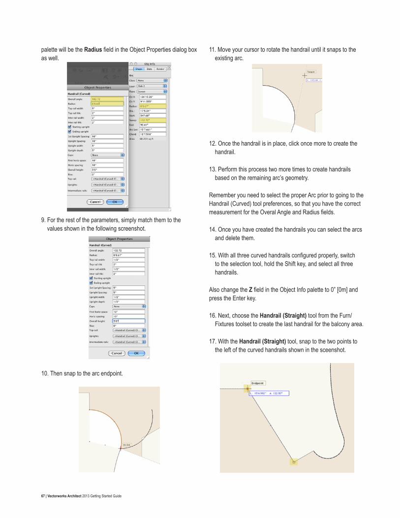
67 | Vectorworks Architect 2013 Getting Started Guide
palette will be the Radius field in the Object Properties dialog box as well.
9. For the rest of the parameters, simply match them to the values shown in the following screenshot.
10. Then snap to the arc endpoint.
11. Move your cursor to rotate the handrail until it snaps to the existing arc.
12. Once the handrail is in place, click once more to create the handrail.
13. Perform this process two more times to create handrails based on the remaining arc’s geometry.
Remember you need to select the proper Arc prior to going to the Handrail (Curved) tool preferences, so that you have the correct measurement for the Overal Angle and Radius fields.
14. Once you have created the handrails you can select the arcs and delete them.
15. With all three curved handrails configured properly, switch to the selection tool, hold the Shift key, and select all three handrails.
Also change the Z field in the Object Info palette to 0” [0m] and press the Enter key.
16. Next, choose the Handrail (Straight) tool from the Furn/Fixtures toolset to create the last handrail for the balcony area.
17. With the Handrail (Straight) tool, snap to the two points to the left of the curved handrails shown in the sceenshot.

68 | Vectorworks Architect 2013 Getting Started Guide
This is the portion of the balcony by the stairs.
18. Then configure the handrail in the Object Info palette to match what is shown in the following screenshot.
19. Don’t forget once the straight handrail is complete to change the Z height in the Object info palette to 0” [0m]
Now the handrails are complete.
20. Switch to a Left Rear Isometric view in the View bar.
21. Also set the Layer Options dropdown menu in the Navigation palette to Show/Snap Others and set Floor 1 to visible.
22. Now render in OpenGL to see your progress.
23. You can also use the Flyover tool to see some other views if you would like.
At this point, you have completed the building model. The only thing left to do is create viewports of our building for better visualization of the final project.
Presenting and Annotating the Final Model
Creating a GroundFor most of you, now that your model is complete, the next step would be to present the model to someone who is not familiar with the project. You can accomplish this with viewports, which will allow you to present various views and other information of your project on one sheet layer or multiple sheet layers.
1. Before you move forward, take a moment to make all of the design layers visible except for Scan1 and Scan 2.
2. You should still be in a 3D view and rendered in OpenGL. If you are not, go ahead and do this.
3. Then use the Flyover tool or switch between the Standard Views menu in the View bar to see the building in its entirety.
You should notice that you currently can see all levels of this building, including the foundation and footing. Typically, you would have some sort of site or ground along with the building to help better visualize the project.
Let’s quickly create an extrude to serve as the site or ground for this building.
4. First, go to Tools > Organization and go to the Design Layers tab.
5. Select the Foundation design layer and click New. Name the new design layer “Site,” and make sure the option Edit Properties After Creation is checked.
6. Click OK, and when the dialog box Edit Design Layers appears, set the Elevation field to -6.5” [0.1651m]. Click OK to return to the list of design layers. The new design layer should be the active layer.
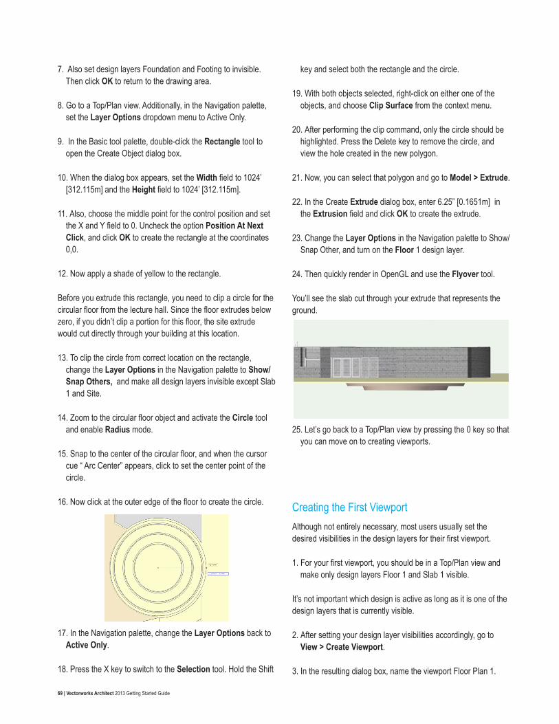
69 | Vectorworks Architect 2013 Getting Started Guide
7. Also set design layers Foundation and Footing to invisible. Then click OK to return to the drawing area.
8. Go to a Top/Plan view. Additionally, in the Navigation palette, set the Layer Options dropdown menu to Active Only.
9. In the Basic tool palette, double-click the Rectangle tool to open the Create Object dialog box.
10. When the dialog box appears, set the Width field to 1024’ [312.115m] and the Height field to 1024’ [312.115m].
11. Also, choose the middle point for the control position and set the X and Y field to 0. Uncheck the option Position At Next Click, and click OK to create the rectangle at the coordinates 0,0.
12. Now apply a shade of yellow to the rectangle.
Before you extrude this rectangle, you need to clip a circle for the circular floor from the lecture hall. Since the floor extrudes below zero, if you didn’t clip a portion for this floor, the site extrude would cut directly through your building at this location.
13. To clip the circle from correct location on the rectangle, change the Layer Options in the Navigation palette to Show/Snap Others, and make all design layers invisible except Slab 1 and Site.
14. Zoom to the circular floor object and activate the Circle tool and enable Radius mode.
15. Snap to the center of the circular floor, and when the cursor cue “ Arc Center” appears, click to set the center point of the circle.
16. Now click at the outer edge of the floor to create the circle.
17. In the Navigation palette, change the Layer Options back to Active Only.
18. Press the X key to switch to the Selection tool. Hold the Shift
key and select both the rectangle and the circle.
19. With both objects selected, right-click on either one of the objects, and choose Clip Surface from the context menu.
20. After performing the clip command, only the circle should be highlighted. Press the Delete key to remove the circle, and view the hole created in the new polygon.
21. Now, you can select that polygon and go to Model > Extrude.
22. In the Create Extrude dialog box, enter 6.25” [0.1651m] in the Extrusion field and click OK to create the extrude.
23. Change the Layer Options in the Navigation palette to Show/Snap Other, and turn on the Floor 1 design layer.
24. Then quickly render in OpenGL and use the Flyover tool.
You’ll see the slab cut through your extrude that represents the ground.
25. Let’s go back to a Top/Plan view by pressing the 0 key so that you can move on to creating viewports.
Creating the First ViewportAlthough not entirely necessary, most users usually set the desired visibilities in the design layers for their first viewport.
1. For your first viewport, you should be in a Top/Plan view and make only design layers Floor 1 and Slab 1 visible.
It’s not important which design is active as long as it is one of the design layers that is currently visible.
2. After setting your design layer visibilities accordingly, go to View > Create Viewport.
3. In the resulting dialog box, name the viewport Floor Plan 1.

70 | Vectorworks Architect 2013 Getting Started Guide
4. Also choose New Sheet Layer from the Create on Layer dropdown menu. This should populate another dialog box.
5. In the New Sheet Layer dialog, set the Sheet Number field to A-1 and the Sheet Title field to 1st Floor Plan. Click OK twice to create the viewport on your sheet layer.
As you can see from the Object Info palette, the entire design is now seen as one viewport.
Viewports can display entire, as well as cropped, views of a drawing, with specified layer and class visibility settings, projection, render mode, and orientation parameters. If you were to make changes to this model from the design layer, the viewports could be easily updated to reflect the changes.
Additionally notice in the Navigation palette that none of the design layers are active. If you go to the Sheet layers tab you’ll see sheet layer 1st Floor Plan is now the active layer. Sheet layers are used to create a presentation version of the finalized drawing and can include viewports, title blocks, notes, and other annotations. Also, to help you discern the difference between these two layers, sheet layers display with a wide gray border that represents the print margin area, while design layers have a thin gray border (when the page boundary is displayed). These two layer types also display with differently colored backgrounds. By default, sheet layers will have a white background, and design
layers will have a tan color in Top/Plan and a green color in 3D.
Adding a Sheet Border and Title BlockSince Sheet layers can display more than viewports to present your final project, let’s go ahead and add a title block and sheet border as well.
1. Select the Sheet Border tool from the Dims/Notes toolset, and double-click anywhere on the sheet layer.
2. When the Sheet Border Preferences dialog box opens, choose Fit to Page for the Sheet Size, and make sure the option Lock to Page Center is checked. (This is why your initial placement of the sheet border was not important.)
3. Also, click the button labeled None to choose your title block. From the Defaults symbol folder choose the symbol US Arch NCS-2 and click OK twice to place the title block.
4. Zoom to the bottom right corner where the title block is displayed.

71 | Vectorworks Architect 2013 Getting Started Guide
5. Now double-click the sheet border to edit the title block fields.
All of the fields listed under the Sheet tab are specific to each sheet layer while the fields under the Project field remain the same on each sheet layer.
Notice that the Sheet Number and Sheet Title Line 1 fields are already populated, as these fields are pulled from the dataset when you created the new sheet layer. Let’s go through quickly and set the rest of the fields appropriately.
6. Make fields Sheet Title Line 2 and Sheet Title Line blank.
7. Enter “As Noted” in the Sheet Scale field.
8. You can enter whatever you like for the Consultant Name and Address fields, but enter your name in the Drawn By field.
9. Input information in the Reviewed By, Submitted By, and Checked By fields if you so desire, but it is also fine to leave them blank.
10. Input today’s date for the Date field. If you like, you can add more information under the Project tab, but at this point you can click OK to display the changes in the title block.
You might notice the viewport and the sheet border overlap slightly, but you can fix this by just clicking and dragging the viewport upward. Alternately, you can nudge the viewport by holding the Shift key and tapping the appropriate direction arrow on your keyboard.
11. Aside from editing the title block you can also edit the
attributes of the sheet border by clicking the Border Settings button in the Object Info palette.
12. For this project we are going change the borders margins. When the dialog box opens, set the Left field under Margins to 1” [0.0254m] and all the remaining fields under Margins to .5” [0.0127m].
13. Once complete, click OK to see the changes to the sheet border and return to the drawing area.
14. Also in the Object Info palette, uncheck the option Show Grids to simplify the border.
Adding AnnotationsTo help keep your model organized, you can also annotate and add dimensions to your viewports so you don’t have to clutter your design layers with these things.
1. To add annotations, double-click the viewport and choose Annotations from the Edit Viewport dialog box. This will take you to Annotations Edit mode.
Here you cannot directly modify any of the objects that reside in

72 | Vectorworks Architect 2013 Getting Started Guide
the design layer. You can only add or remove new information or objects. The first object you are going to add to the annotations is a drawing label.
2. Activate the Drawing Label tool from the Dims/Notes toolset, and click once near the middle of page below the viewport but above the sheet border. This first click sets the drawing label’s bubble location.
3. Now set the text rotation by moving your cursor to the right while holding the Shift key.
4. When the text is horizontal, click once more to create the drawing label. Then Click OK if the Object Properties dialog box appears.
5. Once the drawing label is created, go to the Object Info palette and change the Drawing Title field to 1st Floor Plan.
6. After making this change, click the Exit Viewport Annotations button in the right corner of the drawing.
That’s it for the first viewport.
Creating the Second ViewportNow let’s create another viewport displaying different information. Last time, you created the viewport based on visibilities from the design layers.
1. This time, however, just go to the Navigation palette and right-click sheet layer 1st Floor Plan and choose Duplicate.
Notice that the new sheet layer is automatically made the active sheet layer and is also automatically numbered A-2, but the sheet title still shows 1st Floor Plan.
2. To change this, right-click the duplicated sheet layer and choose Edit. Then change the Sheet Title field to 2nd Floor Plan and click OK.
Notice in the title block that both of these fields have been updated to reflex the changes. You also need to update the drawing label.
3. Double-click the viewport and choose Annotations from the Edit Viewport dialog box and click OK.
4. Now press the X key, switch to the Selection tool, and select the drawing label at the bottom of the page.
5. In the Object Info palette, change the Drawing Title field to 2nd Floor Plan. After you make the change, click the Exit Viewport Annotations button.
The information in this sheet layer is now correct, but you still need to change the actual viewport to display the second floor:
6. Select the viewport and click the Layers button in the Object Info palette.
7. In the Viewport Layer Properties dialog box, make design layers Floor 2, Slab 2, and Roof the only visible layers.
8. Also drag design layer Roof by its number below Slab 2 and click OK to show the changes in the viewport.

73 | Vectorworks Architect 2013 Getting Started Guide
Now the plan views for both floors are complete.
Creating Elevations with ViewportsNext, we shall move on to creating elevations of the building. Although you could again simply duplicate an existing sheet layer and viewport to make these elevations, this time you will start from a design layer.
1. In the Navigation palette, make design layer Slab 1 active.
2. Additionally, set all design layers to visible except for design layers Site, Footing, and the two scan layers.
3. Make sure Unified view is enabled in the View bar, and choose Front from the Standard Views menu in the View bar as well.
4. Next, go to View > Create Viewport. In the Create Viewport dialog box, choose New Sheet Layer from the Create on Layer dropdown menu.
5. When the new dialog box appears, set the Sheet Number to A-10 and the Sheet Title to Elevation 1. Then click OK to return to the previous dialog box.
6. Choose Hidden Line from the Render menu and click OK to create the viewport.
7. Now right-click the viewport and choose Edit Annotations.
8. Just like with the other viewports, active the Drawing label tool and insert a drawing label below the viewport.
9. This time input “North Elevation” in the Drawing Title field in the Object info palette.
10. Click Exit Viewport Annotations in the top right to return to the sheet layer.
11. You’ll be adding another viewport to this sheet layer, so switch to the Selection tool and move this viewport to the top half of the page.
12. After moving the viewport upward, hold the Option key (Macintosh) or the Alt key (Windows) move your cursor to the existing viewport.
You should see that the cursor now has a small plus sign to indicate that a duplicate object will be created.
13. So click and drag the viewport downward to the bottom half of the page. Then release your mouse button to create the duplicate viewport. After the duplicate is created, you can release the Option or Alt key.
14. Right-click the duplicate viewport and choose Edit Annotations.
15. Select the drawing label and change the Drawing Title field in the Object Info palette to South Elevation. Click Exit Viewport Annotations when you’re finished.
16. With the viewport still selected, change the View dropdown menu in the Object Info palette to Back.
Notice that the viewports have a red and white strip displayed around their border to indicate that the viewport needs to be updated.
17. To update a viewport, simply click the Update button in the Object Info palette. While the viewport is selected. You can also select multiple viewports and update them at one time.
18. Now just nudge the bottom viewport until it is aligned with the
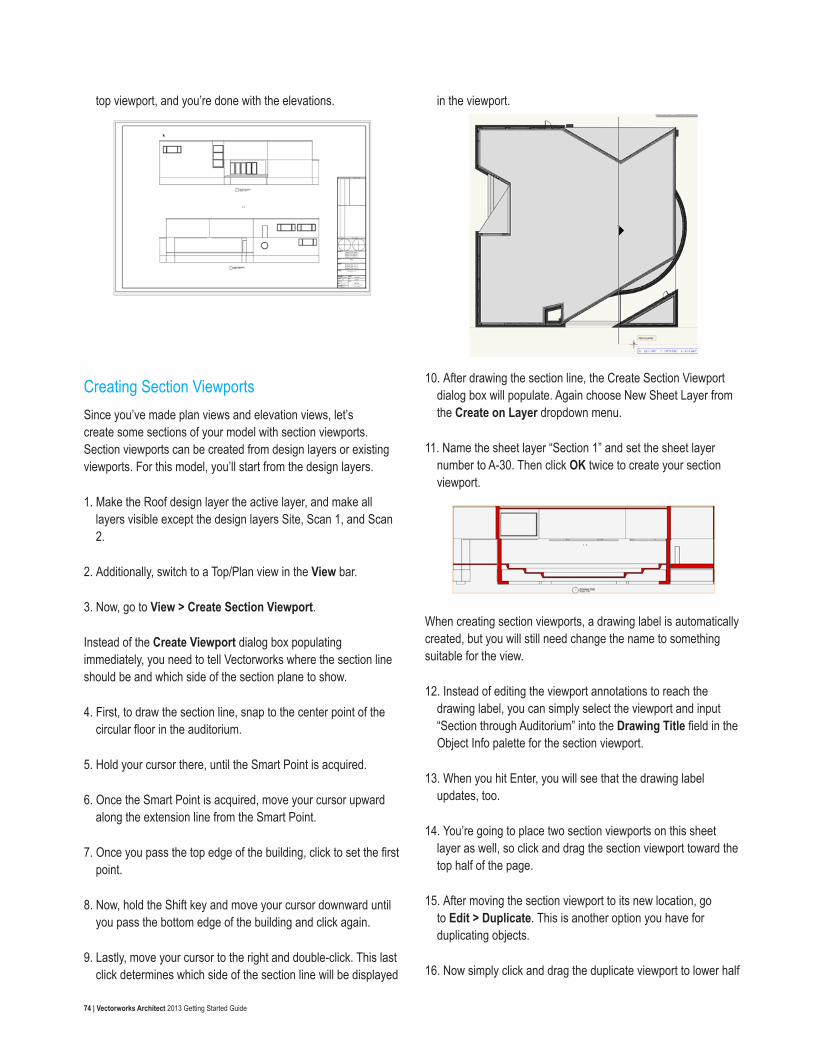
74 | Vectorworks Architect 2013 Getting Started Guide
top viewport, and you’re done with the elevations.
Creating Section ViewportsSince you’ve made plan views and elevation views, let’s create some sections of your model with section viewports. Section viewports can be created from design layers or existing viewports. For this model, you’ll start from the design layers.
1. Make the Roof design layer the active layer, and make all layers visible except the design layers Site, Scan 1, and Scan 2.
2. Additionally, switch to a Top/Plan view in the View bar.
3. Now, go to View > Create Section Viewport.
Instead of the Create Viewport dialog box populating immediately, you need to tell Vectorworks where the section line should be and which side of the section plane to show.
4. First, to draw the section line, snap to the center point of the circular floor in the auditorium.
5. Hold your cursor there, until the Smart Point is acquired.
6. Once the Smart Point is acquired, move your cursor upward along the extension line from the Smart Point.
7. Once you pass the top edge of the building, click to set the first point.
8. Now, hold the Shift key and move your cursor downward until you pass the bottom edge of the building and click again.
9. Lastly, move your cursor to the right and double-click. This last click determines which side of the section line will be displayed
in the viewport.
10. After drawing the section line, the Create Section Viewport dialog box will populate. Again choose New Sheet Layer from the Create on Layer dropdown menu.
11. Name the sheet layer “Section 1” and set the sheet layer number to A-30. Then click OK twice to create your section viewport.
When creating section viewports, a drawing label is automatically created, but you will still need change the name to something suitable for the view.
12. Instead of editing the viewport annotations to reach the drawing label, you can simply select the viewport and input “Section through Auditorium” into the Drawing Title field in the Object Info palette for the section viewport.
13. When you hit Enter, you will see that the drawing label updates, too.
14. You’re going to place two section viewports on this sheet layer as well, so click and drag the section viewport toward the top half of the page.
15. After moving the section viewport to its new location, go to Edit > Duplicate. This is another option you have for duplicating objects.
16. Now simply click and drag the duplicate viewport to lower half

75 | Vectorworks Architect 2013 Getting Started Guide
of the page.
Currently, this section is showing only the right side of the building from the section line. With this second viewport, you’ll flip it to show the left side of the building from the section line.
17. First with the duplicate section viewport selected, in the Object Info palette, change the Drawing Title field to Section Through Auditorium Looking South. Again notice the drawing label also updates when you make this change.
18. Next, click the Reverse Direction button at the bottom of the Object Info palette. This changes the direction of the section line so that it now shows the left side of the section.
Remember, when you see this red and white stripe around your viewport, you need to update it.
19. So click the Update button in the Object Info palette to see what the section looks like on the opposite side of the viewport.
In addition to showing your building section in this orthogonal view, you can also show the section with other projections like Perspective and Oblique.
20. To do this, go to the Object Info palette and for this example choose Perspective from the Projection dropdown menu.
From the Perspective Type dropdown menu, you can use a default value or set a value yourself for the Perspective Distance by choosing Custom.
21. For this instance, choose Custom and set the Perspective Distance field to 30.
22. Then click the Update button to view your changes.
23. After changing the projection, click and drag the viewport back to an appropriate location on the page.
24. Also, right-click this section viewport and choose Edit Annotations, so that you can click and drag the drawing label back to its original location below the viewport.
25. When you exit the Edit Annotations view, the building sections will be complete.
Cropping Viewports and Viewport RenderingNow let’s crop an existing viewport and changing its rendering style.
1. For this example go to sheet layer A-10, which has the building elevation views.
All levels of the building are currently showing in both viewports, but let’s change the bottom viewport so that only the levels above the site or at ground level are visible.
2. First, select the bottom viewport and click the Layers button. Set the design layer Site to visible, and all design layers listed below the Site design layer should be invisible.
3. The viewport needs to be updated now, so click the Update button to do so.
You can see that the ground extrude currently extends much further than the page boundary and that the circular floor from the auditorium is protruding though the bottom. The best way to fix

76 | Vectorworks Architect 2013 Getting Started Guide
this is to crop the viewport.
4. To crop the viewport, right-click or double-click the viewport and choose Edit Viewport Crop.
5. Then using any 2D shape—in this case a rectangle—draw your desired crop box.
6. In this case, start your rectangle a little above the left corner of the building.
7. Then move the cursor to bottom edge of the ground extrude, but make sure it extends a little past the building edge on the right. Then click to create the rectangle crop.
8. When you click Exit Viewport Crop, you should have something similar to this.
Thus far, all of the viewports have been rendered in the Hidden Line rendering, but you can choose any rendering style you want for a viewport and also use them in combination.
9. For example, with the bottom viewport still selected, choose OpenGL from the Background Render dropdown menu in the Object Info palette.
10. Also set the Foreground Render dropdown menu to Hidden Line Rendering and click the Foreground Render Settings button.
11. In the resulting dialog box, check the options Generate Intersecting Line and Sketch Hidden Line Results.
12. Also choose Certain for the Sketch Style. Click OK and click the Update button in the Object Info palette to see the
viewport’s new rendering style.
Dimensioning and Scaling ViewportsAnother important part of annotating your viewport is adding dimensions, which you’ll do now.
1. To start, make sheet layer A-1 the active layer in the Navigation palette.
2. Next, double-click the viewport and select Edit Annotations from the dialog box.
From here, you could use the Dimension tool to dimension specific portions of your building, but there is a quicker approach:
3. Go to AEC > Dimension Exterior Walls.
4. When the Dimension Exterior Walls dialog box appears, choose Floor 1 from the Dimension the Wall on this Layer dropdown menu.
5. Additionally input 12” [0.3048m] in the Apply to Dims Less Than field and click OK to dimension the walls.
In some instances there may be too many dimensions in a particular area, but you can easily select the extraneous dimensions and delete them as shown. Use the screenshot as a

77 | Vectorworks Architect 2013 Getting Started Guide
guide for which dimensions can be removed.
When complete your viewport should look similar to this. If the drawing label appears to be in the way of some of the dimensions, just nudge it downward some.
6. Once you are satisfied with the dimensions, click the Exit Viewport Annotations button.
Your viewport is complete, but now it’s a little too large for the page because of the dimensions. With viewports, you can also change their scale while keeping the scale of the model of the design layer intact.
7. To change the viewport’s scale, go to the Object Info palette.
8. Choose either a default scale from the Scale dropdown menu or choose Custom, which you’ll do for this example.
9. Then input 75 in the Custom Scale dialog box.
10. After you press Enter you will see the viewport scale down accordingly.
11. Reposition the viewport within the sheet border and you’re done dimensioning.
Creating a Final Perspective ViewYou have created plan, elevation, and section views of your building. The last viewport you’ll create will be a simple rendered perspective of the building. You’ll need to return to a design layer
to create your perspective view.
1. So make design layer Floor 1 the active layer from the View bar.
2. Next, go to View > Set 3D View and draw a line from the far top left of the drawing area to the north pad entrance.
3. When the Set 3D View dialog box appears, set both the Viewer Height field and the Look Toward Height to 5’0” [1.524m].
4. Also choose Normal from the Perspective dropdown menu and click OK.
5. Then render in OpenGL.
Here’s the perspective view.
Notice again that you don’t need to show the entire ground

78 | Vectorworks Architect 2013 Getting Started Guide
extrude in the viewport, so crop it before making the viewport.
6. To do this, select the Rectangle tool from the Basic tool palette and draw your crop from the top left—just beyond the building edge—to the bottom right of the ground extrude beyond the building’s right edge.
7. Now, with the rectangle selected, go to View > Create Viewport.
8. You should see a prompt asking if you want to use the selected object as crop. Click Yes, and the Create Viewport dialog box will appear.
9. Name the viewport Perspective 1.
10. Then create a new sheet layer with the sheet number “A-0” and the title “Perspective View.” Click OK to create the viewport.
11. With the viewport selected, set the Background Render dropdown menu to OpenGL and click the Background Settings button in the Object Info palette.
12. When the dialog box appears, set the Detail dropdown menu to Very High and check the option Use Anti Aliasing. Then click OK to return to the sheet layer.
13. Also set the Foreground Render to Hidden Line and click the
Foreground Render button in the Object info palette.
14. Make sure the option Generate Intersecting Lines is checked and click OK.
15. Lastly, click the Update button in the Object Info palette to see the rendering.
If you have Renderworks, you can set the Background Render to Final Quality Renderworks, the Renderworks Background to an HDRI and you’ll get something similar to this.
Printing and Exporting to PDFNow the project is complete. You can continue to add to the project, if you like, by adding sheet borders and dimensions, but from this point you can also output your project for printing. There are several ways to do this.
1. You could simply go to File > Print and send the current page to your printer.
Normally, if you are outputting a large format, it is best to create a PDF first and then print that PDF.
2. To do this, go to File > Export > Export PDF.
Additionally, if you want to export all of your sheet layers or viewports at once, you can use the Batch Export command. Here you can choose all or just specific sheets to export to the PDF.

79 | Vectorworks Architect 2013 Getting Started Guide
The options for setting up pages and printing can vary greatly from printer to printer, so for more specifics, please see the related videos on exporting to PDF and printing.
You have now completed the Architect Getting Started Guide. The guide just scratches the surface of the functionality of this product. Use this guide as a stepping-stone to further exploration of Architect’s capabilities.