Embed Size (px)
Citation preview

Getting Results Guide, applicom® working with RSView32 . 1/18
Getting Results Guide applicom working
with RSView32
The following complete Example in this Getting Results Guide is for a Modbus Plus configuration. If you have to use different Protocols and
other applicom cards, the principles are similar for card configuration, OPC Server configuration and RSView32 OPC
configuration.
Summary
I) About applicom OPC 2
II) applicom® Installation/Configuration 2 A. applicom® Software Installation 2 B. applicom® Hardware Installation 4 C. applicom® Board Configuration. 5 D. applicom® OPC Configuration 10 E. Initializing the applicom® board. 13
III) RSVIEW32 Configuration 13 A. Setting up communication for applicom® OPC server. 13 B. Checking that communications are working in RSVIEW32 16 C. applicom® communications Status in RSViEW32 17

Getting Results Guide, applicom® working with RSView32 . 2/18
I) About applicom OPC applicom international company is a member of Rockwell Automation Encompass Partner Program. applicom international is the manufacturer of the applicom® Multiple Protocols OPC Server. The product runs under MS-Windows 95/98, MS-Windows NT 4.0 and Windows 2000. It enables communications between the RSView32 OPC client application and industrial devices such as PLCs, Remote I/O. An applicom® card can communicate simultaneously to up to 32 different communication ports, each port handling a communication protocol of your choice. The protocol runs on applicom® co-processor based PC interfaces leaving the computer’s CPU available for the RSView32 application. The applicom® Multiple Protocol OPC Server and the applicom® interface cards support the following protocols such as: Modbus (serial RTU), Modbus TCP/IP, Modbus Plus, Uni-Telway, Fipway, Ethway, UNI-TE on TCP/IP, 3964, AS511, TI-Dir, PPI / MPI, Industrial Ethernet ISO Layer 4 and TCP/IP, SucomA, Sysmac-Way, Omron on TCP/IP, Profibus FMS, Profibus DP, Profibus FDL S5, GE SNP-X, GE on TCP/IP SRTP, CEGELEC on TCP/IP, MITSUBISHI on TCP/IP, INTERBUS-S, CANOpen, and DeviceNet. The RSView32 OPC client application can access the following types of data: -bits (internal bits, input bits, output bits) -bytes (internal bytes, input bytes, output bytes) -words (internal words, input words, output words) -double words -floating words « timers » or « counters » of Siemens and Schneider equipments -modem signals
II) applicom® Installation/Configuration A. applicom® Software Installation We strongly recommend installing the software before plugging the card into the computer. 1. Insert the applicom® CD-ROM into the CD-ROM drive and either wait for the “Auto run”, if
enabled on your computer or run “Setup” located in the root directory of the CD. Follow each screen step by step and answer the questions.

Getting Results Guide, applicom® working with RSView32 . 3/18
2. When using RSView32, you will have to select the OPC option during the applicom® software installation.
3. The installation program will ask you for the communication protocol that you are going to install
on your computer. Please, only select the protocol in the list in accordance with your software license and interface card you purchased.

Getting Results Guide, applicom® working with RSView32 . 4/18
After successful software installing, shut-down and power-off the computer. Open up the computer chassis and install the applicom® hardware as follows: B. applicom® Hardware Installation 1. General Information.
You can install up to 8 different applicom® boards in the same computer. The boards can be seated in PCI or ISA slots A board ID from #1 to #8 must be assigned with jumpers on each board.
2. How to assign a Board # on applicom® PCI bus card ?
applicom® PCI cards must be installed in PCI slots. The card’s settings, such as hardware Interrupt and DPRAM memory address are automatically configured by the PC BIOS without any user's intervention. In the case of multiple applicom® board in the same computer, you must configure the board ID #. The default Factory setting is with #1 (see below).
C0 C1 C2 Board ID # 0 0 0 1 1 0 0 2 0 1 0 3
1 1 0 4 0 0 1 5 1 0 1 6 0 1 1 7 1 1 1 8
After your board is well seated and secured with a screw into the computer’s PCI slot, close the computer chassis, power-on the computer, boot-up and log in with Administrator privileges (in Windows NT or 2000). At this stage, the applicom® software and hardware is successfully installed. The board and the protocols now have to be set up.
0 1
Factory-set; Board ID # 1
C2 C1C0

Getting Results Guide, applicom® working with RSView32 . 5/18
C. applicom® Board Configuration. 1. From the Windows Start menu, go to the applicom® folder and run “PcConf”. PcConf a tool to
configure the applicom® cards for protocols.
2. Select the Configuration menu

Getting Results Guide, applicom® working with RSView32 . 6/18
3. From Card #1 to Card #8, select the part number of the board from the dropdown list box, according to your hardware installation. After choosing the type of the board, you have to configure the channels (communication ports) on each card. This Channels Configuration typically depends on the type of the card and the type of the protocol you will install on each channel. Most of the parameters are protocol dependant.
4. To configure the channels, click on “Channels configuration “ button. In this example, we
installed an applicom® Modbus Plus card with ID#1. It has 2 channels. Typically Channel 0 will be installed with Modbus Plus and Channel 1 with an optional Serial link. The default configuration does not have a protocol. To install Modbus Plus on Channel 0, click on the NONE.

Getting Results Guide, applicom® working with RSView32 . 7/18
5. Select the Protocol from the list. In this example, select MODBUS PLUS, and click OK. PcConf will tell you that you are going to change the protocol on this particular channel. Confirm by clicking OK.
6. Now we are back at the Channel overview. MODBUS PLUS is displayed on Channel 0. As we
are not going to use the Serial Link on channel 1, it will remain as Port without Protocol.
7. Now we are going to configure the Modbus Plus port. Click on MODBUS PLUS, and then on
“Modbus Plus Configuration “. The configuration for the Modbus Plus port is Explorer based.

Getting Results Guide, applicom® working with RSView32 . 8/18
To access and adjust the protocol parameters, double click on the different levels in the explorer. 8. The first level in the explorer is the “card” level, where you have to assign the protocol node
address for the applicom® card. In this example we set up the applicom® card to have the Modbus Plus node = 2, because this address is available on the existing Modbus Plus Network. Click OK to confirm to return to the Explorer.
9. In the Explorer, select the second level, which is “Server Equipments”. The applicom® card is
at least a Modbus Plus client (Master), handling polling and reading cyclically from the PLCs. A Server Equipment represents your PLC configured as a server (slave). Here we have to configure each PLC that the applicom® board is going to read or write the data from. Double click on “Server Equipments”, the dialog box below will be displayed.

Getting Results Guide, applicom® working with RSView32 . 9/18
10. Select from the list box an equipment type (a type of server device), according to the type of
PLC that you want the card to communicate with. Click OK. 11. Now we are going to setup the information in order to address each server device (PLC). As the
applicom® software is not protocol dependant, applicom® manages two types of address. The first type is an address for the application level (between the application and the applicom® board). This is the field named “Equipment number”. It is typically a decimal ID that will be used by the RSView32 application to connect to the device with the card. This ID is an “alias” for the network address of the device and it takes care of the protocol’s physical addressing mechanisms such as IP addresses, SAP, TSAP, LSAP ..etc. The physical address of the device is defined in the Equipment address field. In this example, a typical Modbus Plus node address of 10 is used. Click on the Equipment number list box and select an ID for this device. Usually we recommend using the same Equipment number as Network address “Equipment address”. In this example, we have chosen Equipment number 010 and Equipment address 10. Please note that it is not always possible to do this because of the protocol addresses can have a complex syntax.
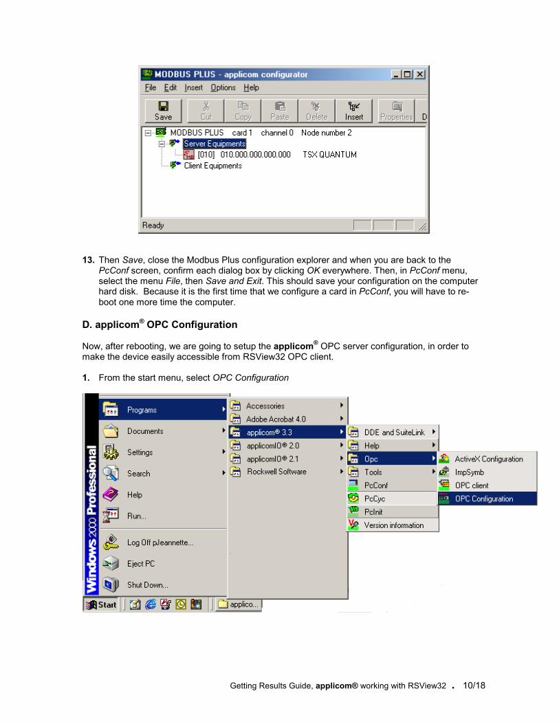
12. It’s always better to comment your choice into “Comment” field. Then click OK. Now you can
see your server Equipment in the tree. Repeat this for each device of the current network.
Getting Results Guide, applicom® working with RSView32 . 10/18
13. Then Save, close the Modbus Plus configuration explorer and when you are back to the
PcConf screen, confirm each dialog box by clicking OK everywhere. Then, in PcConf menu, select the menu File, then Save and Exit. This should save your configuration on the computer hard disk. Because it is the first time that we configure a card in PcConf, you will have to re-boot one more time the computer.
D. applicom® OPC Configuration Now, after rebooting, we are going to setup the applicom® OPC server configuration, in order to make the device easily accessible from RSView32 OPC client. 1. From the start menu, select OPC Configuration

Getting Results Guide, applicom® working with RSView32 . 11/18
2. This should open up the dialog box below, showing the path for your configuration file, the minimum expected refresh period for an OPC group, the syntax delimiter that you can use to comply with your OPC client syntax. Here we have “:”. The default setting is “.” That you can overwrite at your convenience. Then, for each device, you will have to create a Topic, representing the device. Click on “Topics Configuration”
3. At this stage you can create at least one Topic per device (PLC) when you are in “Image
variables” tab. To do it, click on “New”.

Getting Results Guide, applicom® working with RSView32 . 12/18
4. A Topic is a typical object representing your device. To define a Topic, you should assign a name (string based), and the physical path to address the device from applicom® configuration. Typically, you have to address a card from 1 to 8, a channel on the card from 0 to 3 and the Equipment number (ID) that we already defined during with PcConf. In this example, we are going to address a Modbus Plus PLC, which is connected to applicom® card 1, because it is Modbus Plus the channel on this card is 0 and according to our previous PcConf configuration we decided that the Equipment number ID is 10. This makes for instance the Topic named “MOMENTUM”. Then Click OK.
5. Create as many Topics as you want, depending on your Network or Fieldbus architecture.
6. Then Click OK to quit this Topic Configuration and then close the OPC configuration box.
Getting Results Guide, applicom® working with RSView32 . 13/18
E. Initializing the applicom® board. Because the parameters related to the applicom® configuration are not persistent on the board, you have to download this configuration each time you change the configuration (with PcConf) of the card and also each time you power-off the computer. There is a tool named “PCINIT” for the card initialization. You can either start the PCINIT manually from the “Start” menu or you can have it starting automatically then you log in the computer if PCINIT is in the Windows Start Group or when you power-on the computer if you previously installed PCINIT as an NT Service (PCINITSERVICE). Warning: This operation has to be done before using your RSView32 OPC Client application!
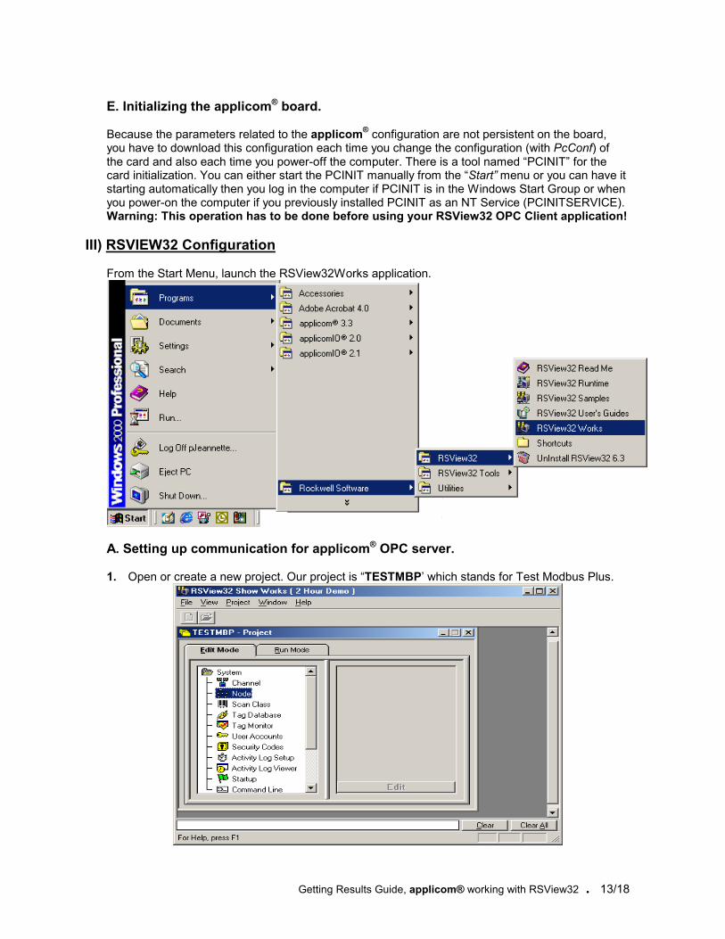
III) RSVIEW32 Configuration From the Start Menu, launch the RSView32Works application.
A. Setting up communication for applicom® OPC server. 1. Open or create a new project. Our project is “TESTMBP’ which stands for Test Modbus Plus.

Getting Results Guide, applicom® working with RSView32 . 14/18
2. In the Node editor, create nodes for OPC server. In the Node Data Source field, select OPC Server
3. Enter a name for this Node, Example: APPLICOM_MODBUS_PLUS. 4. Select the OPC Server Name by browsing the computer. The browser shows you the whole list
of registered OPC servers. For applicom® the name is : APPLICOM.OPCServer 5. Select the Server Type In-Process, Local or Remote.

Getting Results Guide, applicom® working with RSView32 . 15/18
6. In the Tag Database editor, create tags. In the Data Source Type field, choose “Device”. In the Node Name Field, choose the OPC node that you have created before (APPLICOM_MODBUS_PLUS). In the Address field specify the name of the tag in the OPC server. applicom® OPC server supports Tag browsing, so click on button next to this address field. This opens up the OPC Address Browser, where you can find the Server name, and down the explorer, the list of Topic names that you already defined before in applicom® OPC configuration. In our example it is “MOMENTUM”. As soon as you select the Topic in the explorer, the list of possible items appears into the browser. This shows you the generic tag naming for the particular device you have selected. For example a Modbus Plus register as 411111. The Address browser will import automatically this default address into the Address field. You can enter, overwrite and change the address manually. Typically, the complete Address is the combination of the Topic name preceding a syntax delimiter (also defined in applicom® OPC Configuration ) and then the PLC’s register address. In our example we configured the syntax delimiter as “:”, this gives you the full address as follows : MOMENTUM:400001

Getting Results Guide, applicom® working with RSView32 . 16/18
B. Checking that communications are working in RSVIEW32 The simplest way to check if communications are working is to use the tag monitor. The tag monitor shows tag values and states. If you have not created a tag, use the tag browser in tag monitor to create the tag.
Follow the steps below to check for direct driver applicom® OPC server. 1. In the RSView32 Project Manager, open the System folder, double-click Command Line, and
then enter ComStatusOn to start login communication errors. 2. In the RSView32 Project Manager, open the System folder, and then open the Tag Monitor. 3. In The Tag Name column, type the name of a tag that you have created, and then press enter.
If communications are working, a value will appear in the Value column and Valid will appear in the State column. If communications are not working, an error will appear in the State column, and an error message will appear in the activity bar.
If communications are not working
. Check that the communication driver is properly configured. applicom® provides a set of standalone tools for diagnostic purpose such as Diagnostic Profibus, Diagnostic Modbus Plus, Diagnostic TCP… These tools will tell you about the problem to troubleshoot.

Getting Results Guide, applicom® working with RSView32 . 17/18
C. applicom® communications Status in RSViEW32 If you need more detailed information concerning the communication errors from your RSView application, the applicom® OPC server provides a pre-defined Tag named: STATUS . There is one STATUS per Topic. This tag is a 16bit integer (Analog) returning a value according to the trouble. The value returned by this tag “STATUS” is always zero when communications are working, if non zero, then check the protocol help file coming with the applicom® software. At the end of each protocol help file they is a section describing the value of the STATUS according to the protocol communication errors. In our Example we created a STATUS Tag as follows:
Address is: MOMENTUM:STATUS

Getting Results Guide, applicom® working with RSView32 . 18/18
Screen when Communications are working: As you can see below, the current value for the STATUS is = 0, meaning that the communications are working properly. The State for the SPEED tag is set to valid.
Screen when Communications are not working:
As you can see below, the current value for value for the STATUS is = 54, meaning that the communications are not working properly. According to applicom® Modbus Plus help file, STATUS= 54, means that the “Channel is never polled”, the cable has been disconnected … The State for the SPEED tag is set to error.


