Embed Size (px)
Citation preview

White paperJean François Aumont (1) , Bastien Mancini (2).(1) Image Processing Manager, Delair-Tech, (2) Managing Director, Delair-Tech.
Get "the Z" right: methodology for achieving centimeter accuracy using drone-acquired data for mapping and topography purposes.

2Auteurs: Jean François Aumont / Bastien Mancini
Content
1 Introduction
2 Vector and Payload
3 Test field
4 Flights
5 Processing
6 Comparison Method
7 Global View
8 Example of acquisition & processing
9 Results
10 Reprojection
11 Conclusion
DT18-3Bands PPKDT26X-3BandsX PPKGNSS/IMU APX-15
Linear FlightsCover Zones
... 3
... 4
... 6
... 6
... 7... 10... 11... 12... 13... 14... 15
... 4... 4
... 5
... 13... 13

3Auteurs: Jean François Aumont / Bastien Mancini
1. Introduction
The purpose of this document is to analyse the benefits of a precision GNSS/IMU combination on the accuracy of products obtained by photogrammetry (DSM, DTM, orthophotography, stereoscopic restitution, 3D model) with Delair-Tech UAVs.
High accuracy makes it possible to work without Ground Control Points (GCPs), thus reducing overall costs.
The following case study was carried out from December 2015 to March 2016 with our DT18-PPK & DT26X-PPK models.

4Auteurs: Jean François Aumont / Bastien Mancini
2. Vector and Payload
The main specifications of the DT18 are :
◊ 2 kg◊ 2h of autonomy◊ 1.8 m wingspan◊ 1.2 m length◊ 60 km/h cruising speed
Figure 1 - DT18 UAV
The payload consists of a precision IMU/GNSS Applanix APX-15 and an industrial grade camera, with the following specifications :
◊ Sensor installed in landscape mode in the drone’s direction of flight ◊ 3.45 microns (physical size of the pixels), ensuring good image quality ◊ 2448 x 2048 pixels◊ Fixed, stable lens, with 12mm focal length.◊ 1 s maximum frame rate ◊ At 150 m, coverage on the ground of 105 m x 88 m and a pixel on the ground of 4.3 cm
It should be noted that unlike consumer cameras, the industrial grade camera used in DT18 provides accuracy better than 10µs in timestamping the pictures.
For this study, DT18-3bands PPK and DT26X-3bands XL PPK UAVs were used.
2.1 DT18-3bands PPK
2.2 DT26X-3bands XL PPK
The main specifications of the DT26X are :
◊ 15kg◊ Payloads of up to 4kg◊ 2h30 of autonomy◊ 3.3 m wingspan◊ Cruising speed 50 km/h Figure 2 - DT26X UAV

5Auteurs: Jean François Aumont / Bastien Mancini
The payload it carries is the DT3Bands-XL PPK. This consists of a Sony Alpha 7R coupled with an Applanix APX-15 GNSS/IMU, with the following characteristics:
◊ 7392 x 4920 pixels◊ Pixel pitch 4.9µm◊ Focal length : 35mm◊ 1.4s maximum frame rate◊ At 150 m ASFC, coverage on the ground of 155 m x 103 m and a pixel on the ground of 2.1 cm
2.3 GNSS/IMU APX-15
Applanix has been recognized in the aerial mapping field for many years, and its APX-15 UAV model was chosen. The position and attitude characteristics, once the data have been post-processed with POSPac software, are specified as:
◊ 2 to 5 cm in position◊ 0.025° in pitch and roll◊ 0.08° in heading
This system is autonomous, i.e. its results can be obtained without establishing any base on the ground, thanks to the permanent network used by Applanix for post-processing and calculating the trajectory.
It uses carrier-phase tracking, in addition to differential and bi-frequency technology. Furthermore, the GPS data is fused with the IMU data.
The “lever arms” between GPS antenna, IMU and camera are known from the design specifications.

6Auteurs: Jean François Aumont / Bastien Mancini
3. Test fields
Several test fields were used, and for each of them, control points were measured on the ground with a Trimble R6 (post-processed using the fixed base shifts) guaranteeing accuracy of the checkpoints to within 2-3 cm.
Figure 3 – Example of one field with control points
4. Flights
Two types of flights were tested:
◊ Cover zones: because they contain several axes, the whole system is more constrained. In order to resolve ambiguities (camera, lens, distortion and principal point of autocollimation, as well as the angles related to the set-up between the Applanix map and the camera), a 90° cross-flight was performed at two heights above the ground. Side coverage of the axes was set at 60% in order to increase the overlap of images and obtain more autocorrelation points.◊ Linear mapping: this was achieved with just one back & forth flight (2 axes separated by 10m).
In total 7 flights were made:
N Date UAV & Payload Number of images Type Area (km2) or
Length (km)1 2015 December 18th DT18-3Bands PPK 161 coverzone 0.142 2016 March 2nd DT26-3Bands XL PPK 720 coverzone 0.423 2016 March 10th DT18-3Bands PPK 2534 coverzone 1.674 2016 March 10th DT26-3Bands XL PPK 3245 coverzone 4.815 2016 March 11th DT18-3Bands PPK 969 linear 8.006 2016 March 17th DT26-3Bands XL PPK 191 coverzone 0.277 2016 March 17th DT26-3Bands XL PPK 457 linear 4.50

7Auteurs: Jean François Aumont / Bastien Mancini
5. Processing
After the flight, the Applanix navigation data were post-processed using POSPac software in order to integrate the lever arms and calculate the precise trajectory (X,Y,Z,O,P,K).
Two bases were used in order to evaluate the influence of the distance on corrections and results :
◊ A local base station (located at the Ground Control Station, therefore close to the flight area). Here a Trimble R6 receiver was used.◊ A network station, in this case a CSTN beacon, located 40km from the flight area
All data are in UTM 31N Projection and in EGM96 for altimetry.
SD CARD
Base Station(R6 or CSTN)
POSPAC
RAW DATAGNSS & IMU
Lever Arms(from Design)
X, Y, Z, O, P, K

8Auteurs: Jean François Aumont / Bastien Mancini
Figure 4 – Pix4d View
Figure 5 - UAS - Master
Two photogrammetry softwares applications were used: Pix4D and UASMaster.

9Auteurs: Jean François Aumont / Bastien Mancini
The usual process was used, with no GCPs. From Positions (X,Y,Z), Angles (O,P,K) and Pictures, knowing the theoretical camera parameters (focal length, sensor size, principal point, etc…), the aerial triangulation process estimates the “real” positions of the camera (X,Y,Z) as well as its “real” exterior orientations (O,P,K ). The photogrammetry software then estimates the DSM and generates a projection of the image points on the DSM to produce the orthophoto. At the end of the process, every point of each image has unique (XG,YG,ZG) coordinates.
SD CARD
Photogrammetry Software
Images
Camera parameters(from design)
X, Y, Z, O, P, K
X, Y, Z, O, P, K XG,YG,ZG = DSM & Ortho
Camera Parameters(estimated)

10Auteurs: Jean François Aumont / Bastien Mancini
6. Comparison Method
In the following tables we present the differences (RMS) between:◊ Exterior Orientations of the camera as calculated by POSPac (X,Y,Z,O,P,K) and as estimated by the Photogrammetry software (X, Y, Z, O, P, K). This gives (ΔX, ΔY, ΔZ, ΔO, ΔP, ΔK)◊ Coordinates (XG,YG,ZG) of specific points on the ground and their coordinates measured on the field by an independent method, in our case : a Trimble R6 receiver (Xref,Yref,Zref). These reference points are called “CheckPoints”. They should be distinguished from Ground Control Points (GCPs) in that they are not used during the photogrammetry process. In our case this gives (ΔXG, ΔYG, ΔZG)
SD CARD
Photogrammetry Software(Pix4D or UAS Master)
Images
Camera Parameters
(from Design)
X, Y, Z, O, P, K
X, Y, Z, O, P, K XG YG ZG = DSM & Ortho
Camera parameters(estimated)
IndependantTrimble R6
GNSS Ground Receiver
(Xref Yref Zref)
ΔX, ΔY, ΔZ, ΔO, ΔP, ΔK
(ΔXG, ΔYG, ΔZG)

11Auteurs: Jean François Aumont / Bastien Mancini
POSPAC
7. Global view
SD CARD
Photogrammetry Softwares(Pix4D or UAS Master)
Images
Camera Parameters
(from Design)
X, Y, Z, O, P, K
X, Y, Z, O, P, K XG YG ZG = DSM & Ortho
Camera parameters(estimated)
IndependantTrimble R6
GNSS Ground Receiver
(Xref Yref Zref)
ΔX, ΔY, ΔZ, ΔO, ΔP, ΔK
(ΔXG, ΔYG, ΔZG)
Raw DataGNSS & IMU
Lever arms(from design)
With images :
ΔX ΔY ΔZ ΔO ΔP ΔK ΔXG ΔYG ΔZG
The differences are calculated between the “green” and “blue” pyramids as seen here in Pix4D
The differences are calculated between the “real” coordinates of the Point as measured on the ground (center of the target) and the coordinates as seen in the reprojection from the photogrammetry software (here : Pix4D)

12Auteurs: Jean François Aumont / Bastien Mancini
8. Example of Acquisition & Processing
For flight Number 1, acquisition took place on December 18th, 2015 in good weather conditions.161 images were acquired.The raw data were processed in POSPac in order to get exterior orientations.
The dataset was processed in Pix4D and UASMaster, without GCPs.
With UASMaster, the following results were obtained in comparison with checkpoints measured on the ground by an independent GNSS receiver (Trimble R6) :
For this dataset, with UASMaster, the accuracy (RMS) in X,Y,Z on the ground is therefore :
◊ X : 1.3cm◊ Y : 2.7cm◊ Z : 8.9cm
With Pix4D, the following results (RMS on the ground) were obtained :
◊ X : 1.4cm◊ Y : 1.8cm◊ Z : 11.4cm
13Auteurs: Jean François Aumont / Bastien Mancini
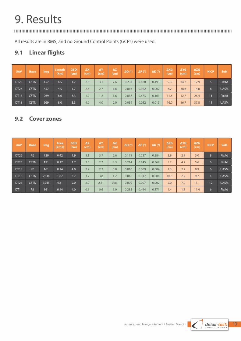
9. Results
All results are in RMS, and no Ground Control Points (GCPs) were used.
9.1 Linear flights
UAV Base Img Length (km)
GSD(cm)
ΔX (cm)
ΔY(cm)
ΔZ(cm) ΔO (°) ΔP (°) ΔK (°) ΔXG
(cm)ΔYG (cm)
ΔZG (cm) N CP Soft
DT26 CSTN 457 4.5 1.7 2.6 3.1 2.6 0.233 0.188 0.493 9.3 34.7 12.9 5 Pix4d
DT26 CSTN 457 4.5 1.7 2.6 2.7 1.6 0.016 0.022 0.007 6.2 38.6 14.0 6 UASM
DT18 CSTN 969 8.0 3.3 1.2 1.2 1.6 0.837 0.673 0.161 11.6 12.7 26.4 11 Pix4d
DT18 CSTN 969 8.0 3.3 4.0 4.0 2.0 0.034 0.052 0.015 16.0 16.7 37.8 11 UASM
9.2 Cover zones
UAV Base Img Area (km2)
GSD(cm)
ΔX (cm)
ΔY(cm)
ΔZ(cm) ΔO (°) ΔP (°) ΔK (°) ΔXG
(cm)ΔYG (cm)
ΔZG (cm) N CP Soft
DT26 R6 720 0.42 1.9 3.1 3.7 2.6 0.171 0.237 0.384 3.8 2.9 5.0 8 Pix4d
DT26 CSTN 191 0.27 1.7 2.6 2.7 3.3 0.214 0.145 0.567 5.2 4.7 5.6 6 Pix4d
DT18 R6 161 0.14 4.0 2.2 2.2 0.8 0.010 0.009 0.004 1.3 2.7 8.9 6 UASM
DT18 CSTN 2534 1.67 3.7 3.7 3.8 1.2 0.018 0.017 0.004 10.3 7.2 9.7 4 UASM
DT26 CSTN 3245 4.81 2.0 2.0 2.11 0.83 0.009 0.007 0.002 2.0 7.0 11.1 12 UASM
DT18 R6 161 0.14 4.0 0.6 0.6 1.0 0.285 0.444 0.871 1.4 1.8 11.4 6 Pix4d

14Auteurs: Jean François Aumont / Bastien Mancini
10. Reprojection
Here is how the checkpoints look in Pix4D after reprojection of the results of the Aerial Triangulation (therefore only using the on-board data, no GCPs at all).
GCPs:
Green cross: Projection of the 3D point computed from marks of the selected GCP.
Yellow cross: Position where the selected GCP has been marked.
Yellow circle: Its radius indicates the zoom level at which the selected GCP has been marked. It defines the area in which the point has to be reprojected when estimating the 3D position. When zooming back out from the image, the smaller the circle, the lower the zoom level of the marked point. The higher the zoom level, the more influence the mark has on the reconstruction.
Blue circle: The position corresponds to the projection of the input 3D coordinate of the selected GCP.
GCP12
15Auteurs: Jean François Aumont / Bastien Mancini
11. Conclusion
DT18PPK and DT26X PPK can be used to obtain a very precise solution without the need to measure ground control points.The absolute accuracy for corridor mapping is between 15 cm and 30 cm in Z.For cover zones, the accuracy is between 2-5 cm in X,Y, and between 5-10 cm in Z.


![Indoor global Positioning System with centimeter accuracy ...sig.umd.edu/publications/Chen_SPM_201611.pdf · The answer is yes as evi-denced by the recent works in [6]–[8]. The](https://img.dokumen.tips/doc/110x75/5f7be663b51c284f973443c8/indoor-global-positioning-system-with-centimeter-accuracy-sigumdedupublicationschenspm.jpg)


![Reference: [1] Nicolas, J., F. Pierron, E. Samain and F. Barlier (2001). Centimeter Accuracy for the French Transportable Laser Ranging Station (FTLRS)](https://img.dokumen.tips/doc/110x75/551b409f550346d31b8b4756/reference-1-nicolas-j-f-pierron-e-samain-and-f-barlier-2001-centimeter-accuracy-for-the-french-transportable-laser-ranging-station-ftlrs.jpg)


