Embed Size (px)
Citation preview

01st June 2006
1
German Contribution to the Review of the Reference Document on Best Available
Techniques in the Cement and Lime Manufacturing Industries
Part II: Cement Manufacturing Industries
Authors: Richard Bolwerk, Gerald Ebertsch, Dr. Manfred Heinrich, Sebastian Plickert, Dr. Martin Oerter Members of the National Expert Group

01st June 2006
2
Annex I: Contribution to energy efficiency Annex II: First waste heat power generation plant using the Organic Rankine Cycle process for
utilizing residual clinker cooler exhaust air Annex III: Example: Electrostatic Precipitator Annex IV: Example: Bag Filter Annex V: High efficiency SNCR Annex VI: Selective Catalytic Reduction (SCR) Annex VII: Example of co-incineration of alternative fuels

01st June 2006
3
1 INTRODUCTION In order to gather information for the German contribution to the review of the BREF „Cement and Lime Manufacturing Industries” a survey was initiated by the German national expert group. Members of the national experts group are representatives from public authorities and the cement manufacturing industries. In the survey data on 42 cement kilns was collected representing nearly all kinds of kilns currently operated in Germany. The clinker production of those plants was more than 92% of total national clinker production in the year 2004. Therefore the results of the survey are concidered as being representative for the current situation in the German cement industry. The reported emissions are mainly cited from the ‘Umweltdaten der Deutschen Zementindustrie’ (environmental data) that are published yearly by the VDZ (German Cements Works Association). This information is based upon all kilns that were operated in 2004. Additionally data for the following contribution was gained from guideline No 2094 of the German Engineers Association VDI (VDI 2094: Emission Control of Cement Plants, March 2003). This guideline was handed over by the German delegation to the European IPPC-Bureau at the kick off meeting of the technical working group on the review of Cement and lime BREF (September 12-13, 2005). For more information beyond this contribution please see VDI 2094. The total number of kilns in Germany with a valid permit is given in the following table:
As at 01.01.2005 Number Capacity
t/d % Kilns with cyclone preheaters
45 114,750 88.3
Kilns with grate preheaters
16 14,070 10.8
Shaft kilns 8 1,200 0.9 Total 69 130,020 100
Rotary kilns 2,112 Shaft kilns 150 Average kiln
capacity in t/d
Table: Number and capacity of kilns with operating permits in the Federal Republic of Germany in the year 2004. Source: Umweltdaten der deutschen Zementindustrie 2004

01st June 2006
4
2 PRESENT CONSUMPTION/EMISSION LEVELS IN GERMANY / APPLIED TECHNIQUES
2.1 Use of energy The theoretical fuel energy demand for cement clinker production is determined by the energy required for the chemical/mineralogical reactions (1700 to 1800 MJ/tonne clinker) and the thermal energy needed for raw material drying and pre-heating. The actual fuel energy use for different kiln systems is within the following ranges (MJ/tonne clinker):
3000-3800 for dry process, multi-stage (3 – 6 stages) cyclone preheater and precalcining kilns,
3100-4200 for dry process rotary kilns equipped with cyclone preheaters, 3300-4500 for semi-dry/semi-wet processes (Lepol-kiln), up to 5000 for dry process long kilns, 5000-6000 for wet process long kilns and 3100-4200 for shaft kilns.
The electricity demand is about 90-150 kWh/tonne cement. More information and modification proposals for the existing BREF see annex I. For the first time in a German cement kiln the Organic Rankine Cycle Process for co-generating power from low-temperature waste heat has been applied. The initial results available indicate that 1.1 MW electrical power could be generated with the given mode of operation of the clinker cooler with a waste heat output of the clinker cooler exhaust air of 14 MW and and exhaust gas temperature of 300°C. More information see annex II. The fuels used in German cement kilns and the energy substitution rate are shown in the following table. Fuel 2004
[million GJ/a] Coal 15.6 Lignite 31.7 Petcoke 3.8 Heavy fuel oil 2.6 Light fueloil 0.2 Natural gas and other gases 0.5 Other fossil fuels 0.7 Total fossil fuels 55.1 Total alternative fuels 40.2 Total thermal energy consumption
95.3
Table: Fuel energy consumption classified by energy sources

01st June 2006
5
Electricity consumption was minimized in some cases by replacing old raw material mills via new mills. The following table gives an overview on the relationship between the energy consumption of the different grinding techniques. It has to be pointed out that it is not always possible to exchange one mill via another grinding device. Furthermore it is worth mentioning that an assessment of the most appropriate grinding technique should always consider also the economic aspects.
Grinding process Energy consumption
Maintenance requirements
Drying capacity
Suitability for grinding to great
fineness Ball mill 100 % minor average good Gutbett roller mill 65 to 50 % minor to major low* average Vertical roller mill 75 to 70 % average high average *) Drying in classifier Table: Comparison of grinding technologies based on key characteristics Source: VDI 2094 1.2 Emissions to the air The most relevant air emissions from cemet kilns are the following:
- dust - nitrogen oxides (NOx) - sulphur dioxide (SO2) - carbon oxides (CO, CO2) - hydrogen chloride - hydrogen fluoride - organic compounds (TOC) - heavy metals - polychlorinated dibenzodioxins and dibenzofurans (PCDD/F)
The following subsidiary processes of a cement plant can be sources for dust emissions:
- crushing of raw material - raw material conveyors and elevators - storage for raw materials and products - grinding mills for raw material, cement and coal - storage of fuels (pet coke, hard coal, lignite) - dispatch of cement
Fugitive dust emissions may be released from open storage, road transport or conveyors of raw material and cement. Typical emissions from German cement kilns are quoted in the following paragraphs. Flue gas abatement techniques are characterized, if applied.

01st June 2006
6
2.2.1 Dust German cement kilns are mostly equipped with electrostatic precipitators (ESP). In some cases also fabric filters are used. The current situation is shown in the following table. The data gathered by the questionnaire covers 42 German kilns (c.f. introduction). 1) 240 °C was reported by using glass fibres with PTFE membrane
The values in brackets refer to extreme values that have been reported in some individual cases. The values out side the brackets represent typical ranges. The overview also allows an estimation of filter dust and dust extraction where applicable. Typical clean gas dust contents (daily mean values) attained by rotary kiln systems equipped with ESP range between < 10 – 30 mg/m3. An example for an electrostatic precipitator operated at a kiln with a clinker capacity of 3700 t/d is given in annex III. Measures for reducing safety caused shutdowns of ESP because of CO-trips see VDI 2094, chapter 2.2.1.2. Safety caused shutdowns of one ESP under optimized conditions see table below. Year Duration in total
(min) Number of yearly shut offs/ Maximum duration
Percentage on kiln operating time (%)
2000 12 7 shut offs / max. 3 min 0,003 2001 29 13 shut offs / max. 7 min 0,009 2002 1 1 shut offs / max.0,5 min < 0,001 2003 6 3 shut offs / max. 4 min 0,001 2004 5 4 shut offs / max 2 min 0,001 After flue gas abatement with fabric filters dust emissions in the range from < 10 – 20 mg/mn
3 as daily mean value were reported. To meet these values layout design of fabric filters like air-to-cloth ratio range from < 0.5 – 2 m3/(m2 min).
Main filter systems
8 fabric filters41 electrostatic precipitators
(2) 10 to 121 to 8pressure loss in hPa
0.1 to 0.21 to 4electric energy demand in kWh/t clinker
90 to 160 1)90 to 190temperature in °C
1999 to 20051962 to 2004year of construction
direct operationcompound operation
0 to 66 (165)0 to 35dust extraction in kg/t clinker (10 to 70) 80 to 20054 to 144 (1,718)amount of filter dust in kg/t clinker
system types and data of operation
amount of filter dust and dust extraction
status: July 2005

01st June 2006
7
The German technical instruction on air quality control (TA Luft 20021) prescribe for the operation of cement kilns an emission limit value for dust of 20 mg/mn
3 (daily mean value, related to an oxygen content of 10 %). Existing installations have to comply with this emission limit value no later than 30th October 2007. If waste is used as fuel the emission limit value for dust range from 10 mg/mn
3 (100 % of rated thermal input comes from waste or more than 40 % of rated thermal capacity comes from hazardous waste) to 20 m g/mn
3 (daily average value, related to 10 % oxygen). The continuously monitored dust emissions from German cement kilns related to the year 2004 can be seen in the following diagram (yearly mean values, 10 % oxygen, 273 K, 1013 hPa).
Fig.: Average dust concentrations in the clean gas of 49 rotary kilns (yearly mean values) The separated dust from dust precipitators is used as product. The measured dust emission values did not depend on the type of fuels. Connected and subsidiary processes Nearly all connected and subsidiary processes of a cement plant can release dust emissions. In principle dust is separated via fabric filters e.g. in the following processes:
- crushing of raw material
1 All emission limit values of the TA Luft 2002 given in the following paragraphs have to be complied with by 30th October 2007.
0
5
10
15
20
25
30
35
40
45
50
No of measurements
Con
cent
ratio
n in
mg/
m3
Dust

01st June 2006
8
- storage for raw materials and cement - grinding mills for raw material, cement and solid fuels - dispatch of cement
In cases like crushing, grinding and dispatch equipment is kept under slight suction. The dust emissions from these sources are < 20 mg/m3. The sources are normally equipped with fabric filters. Conveyors and elevators are constructed as closed systems, if dust emissions are likely to be released from dusty material. Roads used by trucks are paved and cleaned periodically in order to avoid fugitive dust emissions. In addition spraying with water at the installation site is used to avoid fugitive dust emissions. Wherever possible, closed storage systems are used. 2.2.2 Oxides of nitrogen The clinker burning process is a high-temperature process resulting in the formation of nitrogen oxides (NOx). Nitrogen monoxide (NO) accounts for about 95% and nitrogen dioxide (NO2) for about 5% of this compound present in the exhaust gas of rotary kiln plants. High process temperatures are required to convert the raw material mix to Portland cement clinker. Kiln charge temperatures in the sintering zone of rotary kilns range at around 1,450 C. To reach these, flame temperatures of about 2,000 °C are necessary. For reasons of clinker quality the burning process takes place under oxidising conditions, under which the partial oxidation of the molecular nitrogen in the combustion air resulting in the formation of nitrogen monoxide dominates. This reaction is also called thermal NO formation. At the lower temperatures prevailing in a secondary firing unit, the nitrogen bound in the fuel can result in the formation of fuel-related NO. Nevertheless the total level of NOx emissions is almost completely determined by the air borne nitrogen rather than by the fuel fired. Without reduction measures, process-related NOx contents in the exhaust gas of rotary kiln plants would considerably exceed the specifications of the TA Luft 2002 (see below). To reduce the NOx-emissions in Germany process integrated measures and secondary NOx-abatement technologies are applied. In 2004 8 kilns were operated with staged combustion technique, 32 kilns were operated with the SNCR-technique and one kiln with the SCR-technique. The yearly mean values of the NOx emissions in 2004 are depicted in the following diagram.

01st June 2006
9
Fig. : Average yearly NOx concentrations in the clean gas of 49 rotary kilns. Note: In 2004, the emissions of several kilns exceeded the emission values for cement plants specified by the TA Luft 2002 now. The operating permits for these works are based on higher NOx limits. Some of these plants have been shut down or will be shut down within the next few years, respectively, while others will be retrofitted with NOx reduction devices. NOx -Emission limit values in Germany For the operation of cement kilns the TA Luft 2002 prescribes 0.50 g/mn
3 as emission limit value for nitrogen dioxide and nitrogen monoxide, to be indicated as nitrogen dioxide. The emission limit value is defined as daily mean value, related to an oxygen content of 10 % in the waste gas. If waste is used as fuel more than 60% of rated thermal input the emission limit value for nitrogen oxides range from 200 mg/mn
3 (100 % of rated thermal input comes from waste or more than 40 % of rated thermal capacity comes from hazardous waste) to 500 m g/mn
3 (daily average value, related to 10 % oxygen). Existing installations have to comply with the German emission limit values 500 mg/m3 or less than 500 mg/m3 depending on the ratio of waste co-incineration no later than 30 October 2007. Applied process integrated measures The following techniques are applied, that have positive effect on the reduction of NOx emissions arising during the manufacture of cement. Data on the emission reduction efficiency of process integrated measures at the moment are only partly available: - Flame cooling by addition of water to the fuel or usage of liquid wastes with high water content Addition of water to the fuel or directly to the flame or usage of liquid/solid wastes with high water content reduces the temperature and increases the concentration of hydroxyl radicals. This can have a positive effect on NOx reduction in the burning zone and reduction rates of 10-
0,00
0,20
0,40
0,60
0,80
1,00
1,20
1,40
1,60
1,80
2,00
No of measurement
Con
cent
ratio
n in
g/m
3 (NO
x as
NO
2)
NOx

01st June 2006
10
50% have been reported [CEMBUREAU report, 1997], [French report, 2003]. Additional heat is required to evaporate the water, which causes slight additional CO2 emissions (approximately 0.1-1.5%) compared to the total CO2 emission of the kiln. Water injection can cause kiln operation problems, such as reduced clinker output, and undesired clinker formation. For a kiln capacity of 3000 t cli./d the investment cost is estimated at 0.0-0.2 million € and the operating cost at 0.0-0.25 €/t clinker [CEMBUREAU report, 1997]. The NOx-reduction efficiency reported ranges within 10 – 50 % - Low-NOx-burner Designs of low-NOx burners vary in detail but essentially the coal (fuel) and air are injected into the kiln through concentric tubes. The primary air proportion is reduced to some 6-10% of that required for stoichiometric combustion (typically 10-15% in traditional burners). Axial air is injected at high momentum in the outer channel. The coal may be blown through the centre pipe or the middle channel. A third channel is used for swirl air, its swirl being induced by vanes at, or behind, the outlet of the firing pipe. The net effect of this burner design is to produce very early ignition, especially of the volatile compounds in the fuel, in an oxygen-deficient atmosphere, and this will tend to reduce the formation of NOx. NOx reductions of up to 30% are achievable in successful installations [British Cement Association, 1997], but the application of low-NOx burners is not always followed by a reduction of the NOx emissions. Low-NOx burners can be applied to all rotary kilns, in the main firing as well as in the precalciner, and emission levels of 500-1000 mg/Nm3 have been reported [Dutch report, 1997]. The investment cost for a new low-NOx burner is about 200000 to 350000 € for a kiln capacity of 3000 t cli./d [CEMBUREAU report, 1997]. If the existing firing system uses direct firing it must be changed to an indirect firing system to allow combustion with low primary air flow, this will mean an investment cost of about 600000 to 800000 € for a kiln capacity of 3000 t cli./d [CEMBUREAU report, 1997]. - Staged combustion Staged combustion is applied at cement kilns supplied with several combustion stages. This technique is mostly carried out with specially designed precalciners. The first combustion stage takes place in the rotary kiln under optimum conditions for the clinker burning process. The second combustion stage is a burner at the kiln inlet, which produces a reducing atmosphere that decomposes a portion of the nitrogen oxides generated in the sintering zone. The high temperature in this zone is particularly favourable for the reaction that reconverts the NOx to elementary nitrogen. In the third combustion stage the calcining fuel is fed into the calciner with an amount of tertiary air, producing a reducing atmosphere there, too. This system reduces the generation of NOx from the fuel, and also decreases the NOx coming out of the kiln. In the fourth and final combustion stage the remaining tertiary air is fed into the system as "top air" for residual combustion [Dutch report, 1997]. Calciners currently in use differ from one another essentially in the location of the fuel input, the way in which the fuel, kiln feed and tertiary air are distributed, and the geometric configuration [Dutch report, 1997]. Staged firing technology can in general only be used with kilns equipped with a precalciner. Substantial plant modifications would be necessary in cyclone preheater systems without precalciners. If this cannot be combined with an increase in production capacity the manufacturers offer a solution with so-called "small" tertiary air ducting and calciner. In this case only a small proportion of about 10-25% of the total heat needed from the kiln is passed through the calciner, but this is sufficient to produce a reducing zone for decomposing nitrogen oxides
01st June 2006
11
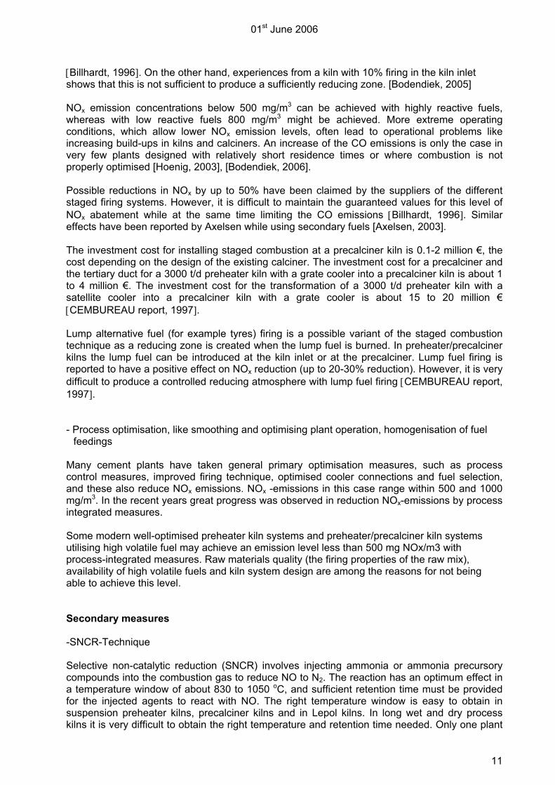
[Billhardt, 1996]. On the other hand, experiences from a kiln with 10% firing in the kiln inlet shows that this is not sufficient to produce a sufficiently reducing zone. [Bodendiek, 2005] NOx emission concentrations below 500 mg/m3 can be achieved with highly reactive fuels, whereas with low reactive fuels 800 mg/m3 might be achieved. More extreme operating conditions, which allow lower NOx emission levels, often lead to operational problems like increasing build-ups in kilns and calciners. An increase of the CO emissions is only the case in very few plants designed with relatively short residence times or where combustion is not properly optimised [Hoenig, 2003], [Bodendiek, 2006]. Possible reductions in NOx by up to 50% have been claimed by the suppliers of the different staged firing systems. However, it is difficult to maintain the guaranteed values for this level of NOx abatement while at the same time limiting the CO emissions [Billhardt, 1996]. Similar effects have been reported by Axelsen while using secondary fuels [Axelsen, 2003]. The investment cost for installing staged combustion at a precalciner kiln is 0.1-2 million €, the cost depending on the design of the existing calciner. The investment cost for a precalciner and the tertiary duct for a 3000 t/d preheater kiln with a grate cooler into a precalciner kiln is about 1 to 4 million €. The investment cost for the transformation of a 3000 t/d preheater kiln with a satellite cooler into a precalciner kiln with a grate cooler is about 15 to 20 million € [CEMBUREAU report, 1997]. Lump alternative fuel (for example tyres) firing is a possible variant of the staged combustion technique as a reducing zone is created when the lump fuel is burned. In preheater/precalciner kilns the lump fuel can be introduced at the kiln inlet or at the precalciner. Lump fuel firing is reported to have a positive effect on NOx reduction (up to 20-30% reduction). However, it is very difficult to produce a controlled reducing atmosphere with lump fuel firing [CEMBUREAU report, 1997].
- Process optimisation, like smoothing and optimising plant operation, homogenisation of fuel
feedings Many cement plants have taken general primary optimisation measures, such as process control measures, improved firing technique, optimised cooler connections and fuel selection, and these also reduce NOx emissions. NOx -emissions in this case range within 500 and 1000 mg/m3. In the recent years great progress was observed in reduction NOx-emissions by process integrated measures. Some modern well-optimised preheater kiln systems and preheater/precalciner kiln systems utilising high volatile fuel may achieve an emission level less than 500 mg NOx/m3 with process-integrated measures. Raw materials quality (the firing properties of the raw mix), availability of high volatile fuels and kiln system design are among the reasons for not being able to achieve this level. Secondary measures -SNCR-Technique Selective non-catalytic reduction (SNCR) involves injecting ammonia or ammonia precursory compounds into the combustion gas to reduce NO to N2. The reaction has an optimum effect in a temperature window of about 830 to 1050 oC, and sufficient retention time must be provided for the injected agents to react with NO. The right temperature window is easy to obtain in suspension preheater kilns, precalciner kilns and in Lepol kilns. In long wet and dry process kilns it is very difficult to obtain the right temperature and retention time needed. Only one plant

01st June 2006
12
with a long dry kiln has so far successfully applied SNCR reduction and reaches efficiencies between 40 and 50% [Görtzen, 2003]. It is important to maintain the temperature range mentioned above. If the temperature falls below this level unconverted ammonia is emitted (so-called NH3 slip) and at significant higher temperatures the ammonia is oxidised to NOx. NH3 slip may also occur at elevated NH3/NO molar ratios, i.e. from a molar ratio of about 1.0-1.2. NH3 slippage has in other sectors of industry sometimes resulted in the formation of aerosols of ammonium chlorides and ammonium sulphates which have passed through the filter and become visible as a white plume above the exhaust gas stack. Unreacted ammonia may be oxidised and transformed into NOx in the atmosphere and NH3 slippage may also result in ammonia enriched dust which may not be recycled to the cement mill [Junker, 2001]. N2O emissions play only a minor role, as spot tests revealed concentrations between 1 and 5 mg/m3 which is approximately the detection limit [VDZ, 1999]. N2O emissions are more likely when urea is used as reducing agent. The most common reducing agent is ammonia solution of about 25% NH3. The transport and storage of ammonia requires additional safety measures [CEMBUREAU report, 1997]. Waste solutions from other production processes can be utilised as ammonia carriers as well. Other possible reducing agents which can be employed on an industrial scale are ammonium salt solutions, dried urea (urea prills), urea solutions, nitrolime or cyanamide and similar other substances [British Cement Association, 1996], [Görtzen, 2003]. However not all these agents have achieved general acceptance to date. The storage and transport facilities have to be designed according to the physical and chemical properties of the respective agent. Most SNCR installations operating in Germany are designed and/or operated for NOx reduction rates of 10 - 50% and emission levels of < 500 - 800 mg NOx/m3. In combination with process integrated measures emission limit values below 500 mg/m as daily mean value are achieved. In this context it is noteworthy that those low values can only be achieved if the initial NOx level is already low as well. - High efficiency SNCR-technique The high efficiency SNCR-Technique is a further development of the SNCR-technique. In one German cement plant the high efficiency SNCR-technique is in operation. There under controlled conditions over 8 lances ammonia water (25 % ammonia solution) is injected into the preheater. The arrangement of the lances is determined by the temperature profile in the riser duct. The injection of ammonia water is process controlled by the measured temperature profile in the preheater nearby the lances. Therefore the NH3 slip and the consumption of ammonia water can be reduced. At the moment trials with governmental financial support of the federal state of Bavaria are carried out to achieve a target value for NOx of 200 mg/m3. Within the first trials it was possible to achieve 200 mg/m3 for some days in case of low initial NOx-levels in the untreated waste gas. During interconnected operation with raw mill on the NH3 slip was low. In direct operation (mill off) the NH3 slip in individual cases was very high. Negative effects on the cement quality because of ammonia however were not detected. More trials under optimized conditions (reducing NH3 slip) are carried out at the moment. More results will be available by the end of 2006. For more information see annex V. - SCR-Technique The SCR-Technique reduces NO and NO2 to N2 with the help of NH3 and a catalyst at a temperature range of about 300 – 400 °C. In one German cement plant this technique is used as high dust treatment technology. The NOx emission limit for this plant is 500 mg/m3 as daily mean value. In 2005 90 % of all daily measured NOx mean values were below this emission limit. The NH3-Slip was not relevant. In order to ensure full-time emission limit compliance, the
01st June 2006
13
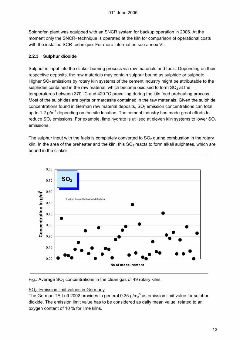
Solnhofen plant was equipped with an SNCR system for backup operation in 2006. At the moment only the SNCR- technique is operated at the kiln for comparison of operational costs with the installed SCR-technique. For more information see annex VI. 2.2.3 Sulphur dioxide Sulphur is input into the clinker burning process via raw materials and fuels. Depending on their respective deposits, the raw materials may contain sulphur bound as sulphide or sulphate. Higher SO2 emissions by rotary kiln systems of the cement industry might be attributable to the sulphides contained in the raw material, which become oxidised to form SO2 at the temperatures between 370 °C and 420 °C prevailing during the kiln feed preheating process. Most of the sulphides are pyrite or marcasite contained in the raw materials. Given the sulphide concentrations found in German raw material deposits, SO2 emission concentrations can total up to 1.2 g/m3 depending on the site location. The cement industry has made great efforts to reduce SO2 emissions. For example, lime hydrate is utilised at eleven kiln systems to lower SO2 emissions. The sulphur input with the fuels is completely converted to SO2 during combustion in the rotary kiln. In the area of the preheater and the kiln, this SO2 reacts to form alkali sulphates, which are bound in the clinker. Fig.: Average SO2 concentrations in the clean gas of 49 rotary kilns. SO2 -Emission limit values in Germany The German TA Luft 2002 provides in general 0.35 g/mn
3 as emission limit value for sulphur dioxide. The emission limit value has to be considered as daily mean value, related to an oxygen content of 10 % for lime kilns.
0,00
0,10
0,20
0,30
0,40
0,50
0,60
0,70
0,80
No of measurement
Con
cent
ratio
n in
g/m
3
SO2
9 values below the limit of detect ion

01st June 2006
14
2.2.4 Carbon monoxide (CO) and total carbon (∑C) The emissions of CO and organically bound carbon during the clinker burning process are caused normally by the small quantities of organic constituents input via the natural raw materials (remnants of organisms and plants incorporated in the rock in the course of geological history). These are converted during kiln feed preheating and become oxidised to form CO and CO2. In this process, small portions of organic trace gases (total organic carbon) are formed as well. In case of the clinker burning process, the content of CO and organic trace gases in the clean gas therefore does not permit any conclusions on combustion conditions. However improper burning conditions in the secondary firing can lead to additional CO-emissions. On the other hand it has to be pointed out that such an increase in the CO emission rate coincides with a decrease in the NOx emissions. In energy conversion plants, such as power stations the exhaust gas concentrations of CO and organically bound carbon are a yardstick for the burn-out rate of the fuels. By contrast, the clinker burning process is a material conversion process that must always be operated with excess air for reasons of clinker quality. Together with long residence times in the high-temperature range, this leads to complete fuel burn-up. Fig.: CO concentration values measured in the clean gas of 29 rotary kilns.
0
1.000
2.000
3.000
4.000
5.000
6.000
7.000
No of measurement
Con
cent
ratio
n in
mg/
m3
6 values below the limit of detectionCO
01st June 2006
15
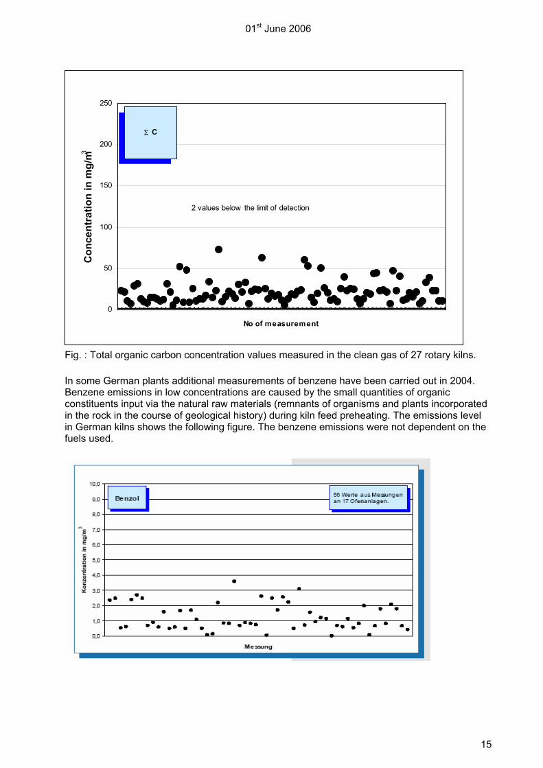
Fig. : Total organic carbon concentration values measured in the clean gas of 27 rotary kilns. In some German plants additional measurements of benzene have been carried out in 2004. Benzene emissions in low concentrations are caused by the small quantities of organic constituents input via the natural raw materials (remnants of organisms and plants incorporated in the rock in the course of geological history) during kiln feed preheating. The emissions level in German kilns shows the following figure. The benzene emissions were not dependent on the fuels used.
0
50
100
150
200
250
No of measurement
Con
cent
ratio
n in
mg/
m3
2 values below the limit of detection
Σ C

01st June 2006
16
2.2.5 Dioxins and furans (PCDD/F) Rotary kilns of the cement industry and classic incineration plants mainly differ in terms of the combustion conditions prevailing during clinker burning. Kiln feed and rotary kiln exhaust gases are conveyed in counter-flow and mixed thoroughly. Thus, temperature distribution and residence time in rotary kilns afford particularly favourable conditions for organic compounds, introduced either via fuels or derived from them, to be completely destroyed. For that reason, only very low concentrations of polychlorinated dibenzo-p-dioxins and dibenzofurans (in short: dioxins and furans) can be found in the exhaust gas from cement rotary kilns. Investigations have shown that their emissions are independent on the type of fuels used. Fig. : Dioxin and furan (PCDD/F) concentration values measured in the clean gas of 39 rotary kilns. In twenty-six cases no PCDD/F was detected. Note: No detection limit can be deduced from the standard. To evaluate the measurement results, inter-laboratory variation of the method (comparison between different laboratories) can be referred to. Pursuant to DIN EN 1948 it amounts to ±0.05 ng ITEQ/m3. (ITEQ: international toxicity equivalent) 2.2.6 Gaseous inorganic chlorine compounds Chlorides are minor additional constituents contained in the raw materials and fuels of the clinker burning process. They are released when the fuels are burnt or the kiln feed is heated, and primarily react with the alkalis from the kiln feed to form alkali chlorides. These compounds, which are initially vaporous, condense on the kiln feed or the kiln dust, respectively, at temperatures between 700 °C and 900 °C, subsequently re-enter the rotary kiln system and evaporate again. This cycle in the area between the rotary kiln and the preheater can result in coating formation. A bypass at the kiln inlet allows to effectively reduce alkali chloride cycles and to thus diminish operational malfunctions. During the clinker burning process, gaseous inorganic chlorine compounds are either not emitted at all or in very small quantities only. Owing to the alkaline kiln gas atmosphere, the formation of hydrogen chloride (HCl) in the exhaust gas can be virtually ruled out. Gaseous inorganic chlorides detected in the exhaust gas of rotary kiln systems are generally attributable to ultra-fine grain size fractions of alkali chlorides in the clean gas dust. They can pass through measuring gas filters, thus feigning the presence of the gaseous compounds.
0,00
0,02
0,04
0,06
0,08
0,10
0,12
0,14
0,16
Con
cent
ratio
n in
ng
ITEQ
/m3
PCDD/F

01st June 2006
17
Fig.: Gaseous inorganic chlorine compound concentration values measured in the clean gas of 38 rotary kilns (given as HCl)
0
5
10
15
20
25
30
35
40
No of measurement
Con
cent
ratio
n in
mg/
m3
91 values below the detection limit
gaseous inorganic chlorine compounds (HCl)

01st June 2006
18
2.2.7 Gaseous inorganic fluorine compounds (HF) Of the fluorine present in rotary kilns, 90 to 95 % is bound in the clinker, and the remainder is bound with dust in the form of calcium fluoride stable under the conditions of the burning process. Owing to the great calcium excess, the emission of gaseous fluorine compounds and of hydrogen fluoride in particular, is virtually excluded. Ultra-fine dust fractions that pass through the measuring gas filter may simulate low contents of gaseous fluorine compounds in rotary kiln systems of the cement industry. Fig.: Gaseous inorganic fluorine compound concentration values measured in the clean gas of 38 rotary kilns (given as HF).
0,0
0,5
1,0
1,5
2,0
2,5
No of measurement
Con
cent
ratio
n in
mg/
m3
106 values below the limit of detection
gaseous inorganic flourine compounds (HF)

01st June 2006
19
2.2.8 Heavy metals The emission behaviour of the individual elements in the clinker burning process is determined by the input scenario, the behaviour in the plant and the precipitation efficiency of the dust collection device. The trace elements introduced into the burning process via the raw materials and fuels may evaporate completely or partially in the hot zones of the preheater and/or rotary kiln depending on their volatility, react with the constituents present in the gas phase, and condense on the kiln feed in the cooler sections of the kiln system. Depending on the volatility and the operating conditions, this may result in the formation of cycles that are either restricted to the kiln and the preheater or include the combined drying and grinding plant as well. Trace elements from the fuels initially enter the combustion gases, but are emitted to an extremely small extent only owing to the retention capacity of the kiln and the preheater. Under the conditions prevailing in the clinker burning process, non-volatile elements (e.g. arsenic, vanadium, nickel) are completely bound in the clinker. Elements such as lead and cadmium preferably react with the excess chlorides and sulphates in the section between the rotary kiln and the preheater, forming low-volatile compounds. Owing to the large surface area available, these compounds condense on the kiln feed particles at temperatures between 700 °C and 900 °C. In this way, the low-volatile elements accumulated in the kiln-preheater-system are precipitated again in the cyclone preheater, remaining almost completely in the clinker. Thallium and its compounds condense in the upper zone of the cyclone preheater at temperatures between 450 °C and 500 °C. As a consequence, a cycle can be formed between preheater, raw material drying and exhaust gas purification. Mercury and its compounds are not completely precipitated in the kiln and the preheater. They condense on the exhaust gas route due to the cooling of the gas and are partially adsorbed by the raw material particles. This portion is precipitated in the kiln exhaust gas filter. To prevent a long-cycle increase in mercury emissions, it may become necessary to limit the concentration of the external cycle, e.g. by continuously or intermittently bleeding part of the dust collected in the electrostatic precipitator from the system. The dust bleed stream is re-circulated to the cement mill as raw material. In case of the energy recovery of alternative fuels (waste fuels) in Germany the mercury input to the kiln is limited regularly (ranges normally within 0.5 to 1 mg/kg). Another possibility is to reduce waste gas temperature after evaporation cooler to improve the precipitation of mercury and its compounds during dust filtration. In principle it has to be pointed out that heavy metal emissions from the clinker production process are influenced by the behaviour of the individual heavy metals in the rotary kiln system, the input situation as well as the collection efficiency of the dust collector. The input situation is determined by the trace element concentrations in the raw materials and fuels processed. As the raw material/fuel mass ratio for clinker production is approx. 10 to 1, this means that the raw material-related inputs are decisive for the emissions. Further details concerning the behaviour of trace elements in the clinker burning process are given in the guideline VDI 2094” Emission control cement plants”. The yearly published environmental data of the German cement industry (VDZ) show that trace element emission concentrations are on a low overall level and are not dependent on the waste incineration. For example, the average values measured in 2004 of the trace elements listed in the German ordinance on waste incineration (17th BImSchV) were below the detection limit in merely about 20% of all cases.

01st June 2006
20
The following diagram depicts the situation for the volatile trace element mercury. A complete overview of the emissions of all German kilns operated in 2004 can be found in Umweltdaten der Deutschen Zementindustrie 2004 ( www.vdz-online.de ). Fig.: Mercury concentration values measured in the clean gas of 40 rotary kilns. 2.2.9 Monitoring of emissions Continuous measurements In the waste gas of German cement kilns regularly dust, NOx, SO2 and mostly CO emissions are monitored continuously. In the case of co-incineration of waste often TOC- and Hg-emissions (especially in the case of co-incineration of sewage sludge) additionally are monitored continuously. Periodic measurements Periodic measurements are carried out for the following pollutants, unless monitored continuously:
- CO - SO2 - TOC
0,00
0,04
0,08
0,12
0,16
0,20
No of measurement
Con
cent
ratio
n in
mg/
m3
9 values below the limit of detection
Hg
01st June 2006
21
Depending on input fuels – especially in the case of waste co-incineration –, process conditions and the relevance of the emissions, additional measurements are carried out for the following pollutants:
- HCl - HF - heavy metals - benzo-a-pyrene - benzene - PCDD/F
Recurrent measurements are usually required at three-year intervals in the case of plants using fossil fuels. In case of co-incineration of waste or alternative fuels recurrent measurements have to be carried out once a year.

01st June 2006
22
3 USE OF WASTE/ WASTE FUELS In principle, the clinker burning process lends itself well to environmentally beneficial waste-to-energy and material recycling applications. The decisive process characteristics for waste processing can be summarized as follows: - Maximum gas temperatures of 2000 °C in the rotary kiln (main firing system) - Gas retention times of about 8 s at temperatures above 1200 °C in the rotary kiln - Solids temperature in the rotary kiln of about1450 °C - Oxidizing gas atmosphere in the rotary kiln - Gas retention times in the secondary firing system of more than 2 s at temperatures above
850 °C; in calciners, the retention times are correspondingly longer - Solids temperatures in the secondary firing system and/or the calciner of 850 °C - Uniform burnout conditions regardless of load variations due to the high thermal capacity of
the rotary kiln - Destruction of organic pollutants due to the high temperatures at sufficiently long retention
times - Sorption of gaseous components like HF, HCl, SO2 on alkaline reactants - High retention capacity for particle-borne heavy metals - Short retention of exhaust gases in the temperature range conducive to de-novo-synthesis of
PCDD/F - Complete utilization of fuel ashes as clinker components and hence, simultaneous material
recycling and energy recovery, regardless of the heating value - No generation of production-specific wastes due to complete material utilization - Chemical-mineralogical incorporation of trace elements into the clinker matrix 3.1 Use of waste as secondary fuels The German cement industry uses primarily hard coal and brown coal as conventional fuels. As the clinker burning process offers favourable conditions for waste co-processing, wastes are substituted for part of these conventional fuels. High calorific waste can substitute primary fuel in cemet kilns. Therefore a constant waste quality is essential (e.g. sufficient calorific value, low heavy metal content (especially mercury and thallium), the waste has to be suitable for the burners). Furthermore the waste fuel has to be available in sufficient quantity. Normally different types of combustible wastes or wastes with separable high calorific fractions are prepared in special waste management facilities. The technologies used to prepare and blend certain waste fuel qualities depend on the characteristics of the input material and the requirements of the users. Even mono waste materials like production-specific wastes are treated and blended prior to use in waste facilities to ensure a homogeneous mixture with nearly constant thermal properties and chemical composition. Only in some cases, wastes can be just used as they are delivered without further processing, for example used tyres or used oil.
01st June 2006
23
Depending on their composition, wastes in cemet kilns are incinerated either in the main firing system or in the secondary firing system. In 2004, some 42 % of the fuel energy demand was provided by waste, corresponding to coal savings of more than 1,000,000 t. Main alternative fuels fired were pretreated industrial waste fractions (approx. 860,000 t)and scrap tyres (approx. 250,000 t) Other waste streams used as fuel substitutes include defined fractions from industrial waste, wood, sewage sludge and other suitable materials. The table below shows the use of alternative fuels in the German cement industry in 2004. In total 2,042,000 t of waste fuels were utilized in 2004 in Germany. Alternative fuel Quantity in 2004 [1000 t/a] tyres / rubber 290 waste oil 100 processed fractions of industrial / commercial waste 863 processed fractions of domestic waste 157 animal meal and fat 439 scrap wood 42 solvents 72 podsol 11 sewage sludge 48 other 20 total 2042 The following summary shows waste groups that have in principle turned out to be suitable for the energy and material recovery in the clinker burning process. - wood - paper - waste oil - podsol - electrode coke - pellets from oil gasification - soot - graphite waste - plastics - solvents - tyres / rubber - textile waste - sewage sludge with suitable Hg-content (see chapter 2.2.9) - other residues (not subject to special surveillance) - suitable fractions of municipal waste or commercial waste similar to municipal waste The requirements for the origin and quality of the mono waste fractions have been defined by restricting the eligible waste streams to individual waste codes. In this connection, the specific conditions of the cement production process and the resultant opportunities and limitations of waste utilization have been taken into account.

01st June 2006
24
The ban on landfilling of unprocessed municipal waste in Germany has led to an increasing number of mechanical-biological treatments plants in operation. As a consequence the utilization of pre-treated mixed municipal waste fractions is an issue of growing concern. After suitable pre-processing, individual municipal or commercial waste fractions can meet the requirements for environmentally compatible reuse in cement plants. Use of Solid Waste The important characteristics for waste fuel are the calorific value, water content, sulphur, chlorine and heavy metal content. Source selection may be the first action to take into account for monostreams to reduce of materials, that might cause operation or quality problems in the cement process like heavy metals or PVC ( mainly responsible for the chlorine content). In mixed wastes heavy metals can be separated in a screening step. The main part of the heavy metals is found in the fine fraction. Furthermore non ferrous elements can be selected by eddy current separators. PVC appears in a wide range of particle sizes, so screening processes are not suitable to discharge PVC. It can be separated by automatic sorting, e.g. auto recognition of plastics by infrared spectroscopy. Not every combustible solid waste is suitable as fuel in the clinker burning process. Solid waste can be an inhomogeneous mixture of very diverse components: combustible fractions (e.g. paper-, cardboard, plastics, rubber, and wood residues) and varying amounts of inert materials (e.g. sand, stone, ceramics, ferrous / non-ferrous metals and organic wet materials). Waste like mixed municipal waste, mixed commercial waste or mixed construction and demolition waste has to be pre-treated in waste management facilities to separate the high calorific fraction. The extent of the waste treatment operation, such as sorting, crushing, pelletising, depends on the waste fuel application. More information see BREF “Best Available Techniques for the Waste Treatments Industries”, chapter 4.5 “Techniques to consider for the preparation of waste to be used as fuel”. Solid fuel preparation technologies vary considerably depending on the source and type of the
waste, and on the requirements of the cement industry. One important requirement results from
the used transfer and firing system to convey waste fuel into a kiln:
- main firing system (at the kiln head/outlet, injection of waste fuels via lances).
Highly abrasive wastes such as dried sludge and unusal particle shapes and sizes can
produce operational problems. When pneumatic transfer systems are used to convey
solid waste fuel in the kiln, plugging and damage to rotating parts can be avoided (the
system functions entirely without moving parts). The amount of conveying air injected
into the kiln along with the waste is negligible in terms of kiln combustion stoichiometry.
Greater particle size dictate large pneumatic convey lines and blowers. Therefore
important processing steps are the size reduction and the soft pelletising of the waste

01st June 2006
25
fuel. (typically particle size is no larger than 250 (?) mm) The advantage of compacting
by soft pelletising is the improvement of flow and dosage characteristics of the fuel.
- secondary firing system (the fuel is fed via kiln inlet, the riser between the rotary kiln inlet
and the lowermost cyclone stage or the calciner).
The size restriction for solid waste fuel is not important for the secondary firing system.
Even whole tyres can be introduced via the kiln inlet. Furthermore waste with high ash
content can be used.
Use of Liquid Waste Liquid waste fuels are normally prepared by blending different wastes like used solvents or waste oil with suitable caloric values in special waste management facilities. Normally only simple pre-treatment (removal of bottoms, sediments and water) is necessary. In some cases, e.g. machining oil/emulsion, chemical processes are necessary to remove metallic pollutants and additives. Liquid waste fuels mostly are hazardous wastes. This has to be taken into account when handling (e.g. storage, feeding) liquid waste fuel. Therefore vapour recovery is used to avoid emissions of organic compounds. Vapour recovery systems are operated in a way which ensures that the flow of organic substances is permitted only upon connection of the vapour recovery system, and that the vapour recovery system and attached facilities release no gas to the atmosphere during normal operation, with the exception of releases necessary for safety reasons. More information for the use of secondary fuels see VDI 2094 chapter 4.1. For examples of waste co-incineration see annex VII. The main types of waste fuel that have been used for co-incineration in German cement
industries in 2003 and 2004 are shown in table below.
Type of waste fuel
t/a 2003
t/a 2004
Liquid waste fuel Waste oil Blended waste
(hazardous) 116 000 100 000
Used solvents Blended waste, included mono wastes are to be declared with waste code (hazardous)
48 000 72 000
Solid waste fuel
End-of-life tyres
Mono waste 247 000 290 000
Wood Mixed waste, included mono wastes are to be declared with waste code (can be hazardous)
48 000 42 000
Animal meal Mono waste 452 00 439 000Sewage sludge Mono waste 4 000 48 000

01st June 2006
26
Bleaching earth Mono waste
(hazardous) 20 000 11 000
Production –specific waste
Mixed waste, included mono wastes are to be declared with waste code
626 000 862 000
Seperated fractions of mixed municipal waste
Fuel quality depending on the used processing steps
155 000 157 000
Table: Quantities of waste fuel co-incinerated in German cement industry (Daten vdz)
Waste Quality Requirements
The aim of a quality assurance is to attain and ensure constant qualities for the waste fuels used. Those fuels that are mainly produced from process related industrial wastes mono-streams are easier to handle because of their constant qualities. Calorific fractions of inhomogeneous wastes, like mixed solid wastes from different sources, separated fractions from mixed municipal waste, the monitoring requirements are set higher to attain a reliable quality with constant low pollutant input. Regular sampling and analysis of the in- and output of the waste management facility and in the delivery into cement plant are necessary. In order to assess and control the suitability of waste materials several criteria can be applied. To start with it might be necessary to get a description of the waste materials. In this context the origin also plays a decisive role. Furthermore some key parameters like the calorific value, the chlorine and the ash content should be known. In case of pre-treated mixed fractions of municipal waste it can also be necessary to analyse the content of trace elements. In this context the main focus should be given to mercury. This trace element has a high volatility. In order to control the mercury emissions it might therefore be necessary to limit the input into the system via an applicable control procedure. German regulators and plant operators have developed individual systems to assess and control the suitability of alternative fuels arising from mixed waste fractions. These systems are mainly focussed on the trace element content. Apart from that the chlorine content of the materials plays an important role. Chlorine may have a negative impact on the production process. The acceptable Chlorine concentration therefore depends on the individual situation on site. Typical ranges are from < 1 – 2 %. The following table depicts typical input criteria for suitable waste fuels. If an alternative material meets the following values the recovery in the clinker burning process will be environmentally sound and safe. Trace element
Unit Concentration
Arsenic mg/kg 13
Cadmium mg/kg 9
Cobalt mg/kg 12
Chromium mg/kg 250
Copper mg/kg 700*

01st June 2006
27
Mercury mg/kg 0,5 – 1
Manganese mg/kg 500
Nickel mg/kg 100
Lead mg/kg 400
Antimony mg/kg 120
Thallium mg/kg 1 – 2
Vanadium mg/kg 25
Tin mg/kg 70 * Higher values may occur in individual samples These criteria should partly not be applied on wastes streams coming from well known sources (e.g. used tyres, material coming directly from industrial processes etc.). Apart from that it has to be pointed out that also other materials that do not meet all of these values can be recovered as well. In these cases it might be necessary to take plant specific aspects into consideration. In case of co-incineration of sewage sludge the Hg-input has to be monitored regularly because of the possible mercury residues. 3.2 Use of wastes as secondary raw materials The use of wastes as secondary raw materials in the clinker burning process involves the substitution of the oxides contained in the secondary raw materials such as calcium oxide (CaO), silica (SiO2), alumina (Al2O3) or iron oxide (Fe2O3) for the respective raw material constituents. Other alternative materials are supplied as interground additives to the grinding plants or cement blending plant. Also, suitable industry by-product gypsum lends itself for use as a sulphate component. An overview of eligible secondary raw materials is given in the following table. Raw material group Examples of waste streams Ca group Industrial lime
Lime slurries Carbide sludge Sludge from drinking water treatment
Si group Spent foundry sand Fe group Pyrite cinder
Synthetic hematite Red mud
Si-Al-Ca group Fly ashes Slags Crusher fines
S group Industry byproduct gypsum F group CaF2
Filter sludges Main alternative raw materials are industry gypsum (428 000 t/ 2004) and fly ashes (378 000 t / 2004). The feeding of gypsum take place in the blending plant. Fly ashes, generated by the

01st June 2006
28
combustion of coal in power plants, can be used both as raw material in the production of clinker (mainly for its content of alumina) and as inter-ground additive for the cement. Fly ash can substitute usually 5-40 % of the Portland cement clinker. Pre-condition is a low content of unburned coal. The recoverable calorific value of carbon rich ashes (up to 20% C is possible) can be used in the cement clinker process. Other types of waste that substitute raw materials are spent foundry sand (151 00 t/2004), mill scales, soil containing oil and paper sludge. Like ash from conventional fuels, the ash from the secondary fuels provides mineral components for the cement clinker. The ternary diagram in Figure 1 shows the composition of different fuel ashes and secondary raw materials, for which the contents of the main components CaO, SiO2, Fe2O3 and Al2O3 are represented. As can be seen, the clinker has a defined composition which is crucial to the characteristic hydraulic properties of the cement. This means that all raw materials and fuel ashes must be carefully matched in terms of mineral composition and feed rate to obtain the desired clinker composition. The secondary raw materials enter the clinker burning process or the calciner via the raw meal path or via the kiln inlet and/or the calciner. During the preheating phase in the preheater, organic components may be released from the kiln feed. When processing secondary raw materials, these must therefore be checked for potential releases of volatile organic constituents and the feed point selected accordingly, i.e. kiln inlet or calciner. Alternatively, the wastes can also be subjected to thermal pre-treatment and added to the raw meal path in the burned-out state. Spent foundry sand, for example, should normally be fed to the kiln inlet. Residual organic binder used in chemically bonded sand cast systems can be decomposed in the preheater. Pre-treatment of spent foundry sand (separation of dust) can reduce the content of heavy metals. Requirements to consider in the selection and use of waste as raw material: - the waste consists primarily of the clinker components - low heavy metal concentration, the content in waste fuel or primary raw material can be
taken in account for the limit value - regular monitoring of the secondary material with sampling and analysis of used wastes

01st June 2006
29
Plastics, rubber
Hard coal
Shredded tyresClinker
Brown coal
0
0
0
Al O + Fe O in %2 3 2 3
SiO in %
2
CaO
in %
Roasted pyrite
Podsol
20
20
20
40
40
40
60
60
60
80
80
80
100
100
100
Figure 1. Ternary CaO, SiO2 and Al2O3/Fe2O3 diagram for cement clinker and the ash constituents of different raw materials and fuels 3.3 Impacts of waste co-processing on the emission behaviour
Dust emissions from the clinker burning process remain unaffected by the co-processing of wastes. Factors determining heavy metal emissions from the clinker production process are the behaviour of the individual heavy metals in the rotary kiln system, the input situation as well as the collection efficiency of the dust collector. The input situation is determined by the trace element concentrations in the raw materials and fuels processed. As the raw material/fuel mass ratio for clinker production is approx. 10 to 1, this means that the raw material-related inputs are decisive for the emissions. In operating practice, the processing of wastes may result in a decreased or increased total input of individual elements into the kiln system. Because of the high retention capacity for particle-borne heavy metals of the preheater and dust collector, the co-processing of waste has only a minor influence on heavy metal emissions from the clinker burning process. Depending on the exhaust gas temperature, mercury is present in particle-borne and/or vapour form in the dust collector. To control mercury emissions, it may therefore become necessary to limit waste-related mercury inputs into the kiln system. When

01st June 2006
30
firing secondary fuels recovered from mixed waste fractions, a routine receiving analysis may be required for monitoring the heavy metals input. The inorganic exhaust gas constituents NOx, HCl and HF remain unaffected by the choice of the feedstock. According to current knowledge, the processing of wastes in the cement production process has no significant effects on these emissions. The same applies to the emission components SO2, CO and TOC provided that the input of volatile sulphur compounds or volatile organic compounds via the raw meal path is not increased through the processing of waste. The combustion conditions in rotary kiln systems ensure low emission concentrations of PCDD/F (dioxins and furans). Wastes likely to contain relevant concentrations of persistent organic substances (e.g. PCB-laden spent oil) are fed via the main firing system to ensure their reliable destruction. If there are doubts about the feed point selection in the individual case, reference measurements with and without waste processing should be performed. Indications from comprehensive measurement programs are that in operating practice, PCDD/F emissions are well below the prescribed limit of 0.1 ng I-TEQ/m3, regardless of the waste processed. 3.4 Impacts of waste co-processing on product quality The use of wastes in the clinker burning process may change the trace element concentrations in the cement product. Depending on the total input via the raw materials and fuels, the concentration of individual elements in the product may increase or decrease as a result of waste processing. As cement is blended with aggregates (e.g. gravel, sand) for the production of concrete or mortar, it is the behaviour of the trace elements in the building material (concrete or mortar) which is ultimately decisive for evaluating the environmentally relevant impacts of waste co-processing in the clinker burning process on the product quality. Heavy metal releases from mortar and concrete are low. Results from comprehensive tests confirm that the heavy metals are firmly trapped in the cement brick matrix. In addition, dry-packed concrete offers high diffusion resistance which further counteracts the release of heavy metals. Tests on mortar and concrete test cubes have shown that the heavy metal concentrations in the eluates are noticeably below those prescribed by the German Drinking Water Ordinance, for instance. Storage under different and partly extreme conditions has not led to any environmentally relevant releases. This also holds true when the sample material is crushed or comminuted prior to the leaching tests. Careful selection and monitoring of the secondary materials ensure that the co-processing of wastes does not result in heavy metal emissions of any environmentally harmful magnitude. The heavy metal emissions are partly orders of magnitude below the applicable air pollution control standards. The co-processing of waste has no negative impact on the environmental quality of the product. Under these conditions, cement can continue to be used without restrictions for mortar and concrete production. The recyclability of these materials remains completely unaffected.
01st June 2006
31
The German VDZ analyses the trace element content in the German cements on a regular basis. The last values have been published for 2001. A comparison with results from earlier investigations showed that there is no increase in the trace element content of the cements although there has been a remarkable increase in the use of alternative materials ov er the respective period.

01st June 2006
32
Annex I: Contribution to Energy Efficiency Modification proposal concerning BREF „Cement and Lime“ Stand 12.01 1.3 Present consumption/emission levels 1.3.2 Use of energy Chapter 3, page 23 … The theoretical fuel energy demand for cement clinker production is determined by the energy required for the chemical/mineralogical reactions (1700 to 1800 MJ/tonne clinker) and the thermal energy needed for raw material drying and pre-heating. The actual fuel energy use for different kiln systems is in the following ranges (MJ/tonne clinker): 3000-3800 for dry process, multi-stage (3 – 6 stages) cyclone preheater and precalcining kilns, 3100-4200 for dry process rotary kilns equipped with cyclone preheaters, 3300-4500 for semi-dry/semi-wet processes (Lepol-kiln), up to 5000 for dry process long kilns, 5000-6000 for wet process long kilns and 3100-4200 for shaft kilns. The electricity demand is about 90-150 kWh/tonne cement. 1.4.2 Use of energy Chapter 4, page 31: Kiln systems with multi-stage (3 to 6 stages) cyclone preheaters with integral calciner and tertiary air duct are considered standard technology for ordinary new plants. Under optimised circumstances as during performance tests such a configuration will use 2900-3300 MJ/tonne clinker. Practical experience shows that the energy consumption of even these plants rises up to 3000-3600 MJ/tonne clinker as an annual average because of suboptimal plant utilisation and un-scheduled shutdowns and start ups of the systems. These challenging values can just be achieved by implementing thermal energy optimization measures [VDI2094] including: Cooler - installation of a stationary preliminary grate - use of cooler grate plates offering a greater flow resistance to provide more -.uniform cooling air distribution - controlled cooling air supply to the individual grate sections Kiln - optimized kiln firing systems - uniform operating conditions - optimization of process control - near-stoichiometric, but oxidizing kiln conditions - low thermal loading for a long refractory lining service life - use of mineralizers - reducing air-in leakage Calciner - low pressure drop

01st June 2006
33
- uniform distribution of the hot meal in the kiln riser - minimal coating formation due to low circulation of alkalis - extensive precalcination of the raw meal - high fuel flexibility Preheater - low pressure drop and a high degree of heat recuperation in the cyclones - high cylone collection rate - uniform meal distribution over the gas duct cross-sections - uniform distribution of solid and gas streams in a two-string preheater - additional cyclone stages Material handling - homogenizing and even feeding of kiln feed material - homogenizing and even feeding of fuels But even kiln systems meeting all the afore mentioned criteria might achieve a higher energy demand because of several other impacts affecting the energy consumption of up-to-date plants with precalciners and cyclone preheaters [Cement International], e. g.: - raw material properties like moisture content or burnability - use of fuels with varying properties - use of a gas bypass system - target clinker quality - kiln size and capacity The local raw material situations vary widely when looking at moisture or burnabilty. As a matter of fact, the throughput and the moisture content of the raw materials and fuels, which have to be dried by the remaining exhaust gas heat, determine the appropriate number of cyclone stages. With a reduced need for drying heat an additional sixth cyclone stage saves about 60 MJ/tonne clinker compared to a 5 stage preheater. But in the case of water contents in the raw material of more than 8 m.-% it’s cost- and also energy-effective to do without a fifth or even a fourth cyclone stage. Of course this induces higher thermal losses with the raw gas leaving the preheater. Just looking at the kiln-preheater-system a 4 cyclone preheater instead of a preheater with 5 cyclones costs about 90 MJ/tonne clinker. With only 3 cyclone stages the difference in energy demand rises further to more than 250 MJ/tonne clinker. But by using the thermal energy of the raw gas for the essential raw material drying the over-all efficiency of the whole plant is not affected. Today it has become common practice to operate the calciner with a wide range of fuel grades, from highly reactive to extremely unreactive. Even in the kiln firing not only highly reactive but also fuels which have poor burnout behaviour as well as secondary fuels are used. A comparison between identical kiln systems fired with hard coal on the one hand and lignite on the other hand, both commonly used fossil fuels, shows a difference of nearly 100 MJ/tonne clinker due to diverse fuel qualities. The use of low reactive or coarse fuels compared to e. g. a fine ground, dry and high calorific coal might result in an additional energy demand of more than 300 MJ/tonne clinker, but inherently preserving valuable fossil resources when using byproducts or wastes. With both raw materials and fuels chlorine, sulphur and alkalis attain to the kiln system, resulting in inner circles between kiln and preheater. At higher concentrations these cycles cause deposit formation in the area of the kiln inlet, the calciner and the two bottom stages. As a uniform kiln operation with minimised disturbances is the basis for an energy efficient clinker production, shutdowns because of coating formation should be avoided. Hence high circulation of alkalis,
01st June 2006
34
chlorine and to a lower extent sulphur enforces the use of a gas bypass at the kiln inlet. By removing part of the process gas not only chlorine, sulphur and alkalis are discharged. The removal of precalcined dust and hot gas leads as a consequence to a higher specific energy consumption of about 6-12 MJ/tonne clinker per percente of removed kiln inlet gas. While the mentioned values are valid for a kiln system with a capacity of 3000 t/d the production capacity has an influence on the energy demand as well. Burning clinker in kilns with a higher capacity of e. g. 5000 t/d saves about 100 MJ/tonne clinker while the energy consumption of smaller kilns, e. g. producing 1500 t/d, is up to 200 MJ/tonne clinker higher. These effects are mainly due to different wall heat losses per tonne of clinker produced. An evaluation of a kiln’s energy consumption necessarily has to take these effects into account. In doing so a simple addition of several aspects is not suitable as they might interfere. As a conclusion the BAT level for the thermal energy consumption of a modern kiln system with cyclone preheater (3 to 6 stages depending on raw material moisture) and precalciner is a range between 3000-3800 MJ/tonne clinker. 1.5 Best available techniques for the cement industry Chapter 5, page 48: … Process selection The selected process has a major impact on the energy use and air emissions from the manufacture of cement clinker. For new plants and major upgrades the best available technique for the production of cement clinker is considered to be a dry process kiln with multi-stage (3 to 6 stages) preheating and precalcination. Under optimised circumstances (e.g. during performance tests) the associated BAT heat balance value is 2900 to 3300 MJ/tonne clinker, depending on the production capacity and with use of high calorific fuels like coal or lignite or fuels with comparable qualities only. Local conditions like raw materials with a high moisture content or a lower burnability increase the energy demand. Also the use of fuels with different properties and the installation of a gas bypass at the kiln inlet, both BAT, result in higher energy demands. Thus practical heat balance values of 3000 to 3800 MJ/tonne clinker as yearly average values are considered as BAT: 3 stages: 3400 to 3800 MJ/tonne clinker 4 stages: 3200 to 3600 MJ/tonne clinker 5 stages: 3100 to 3500 MJ/tonne clinker 6 stages: 3000 to 3400MJ/tonne clinker

01st June 2006
35
Annex II: First waste heat power generation plant using the organic Rankine Cycle process for utilizing residual clinker cooler exhaust air
Reference Literature E. Baatz, G. Heidt, Heidelberg/Germany, First waste heat power generation plant using the organic Rankine Cycle process for utilizing residual clinker cooler exhaust air;

01st June 2006
36
Annex III Example: Electrostatic Precipitator Description: In cement plants electrostatic precipitators have become successfully established for dust collection from rotary kiln exhaust gas and clinker cooler (grate cooler) exit air because of their high efficiency, low pressure loss, high availability and energy efficiency. An example of an modern EPS at an German cement kiln for the cleaning of the rotary kiln exhaust gas is given below. ESP-characteristics: Capacity of the kiln: 3700 t/d Design: 4 fields horizontal Number of filter zones: 4 Filter area: 24 247 m2
Residence time in the electric field: 17 – 20 s Cleaning: mechanical / pneumatic Exhaust gas volume: mill off: 400 000 Nm3/h mill on: 490 000 Nm3/h Current-strength, field 1 - 4: ra. 2 000 Ma Filter-voltage, field 1 – 4: ra. 65 kV Clean gas dust content: < 10 mg/m³ Operational data: Maintenance 1 check per year Pressure drop spray tower: 4 mbar EPS: 2,5 mbar Use of secondary fuels: Up to 75 % of the energy demand can be utilized by the use of secondary fuels. The use of secondary fuels has no influence on clean gas dust content. The size and electric power consumption of ESP’s rises exponentially with decreasing clean gas dust content. ESP depend on defined raw gas conditions (temperature and humidity) for optimum operation. The lifetime of an ESP can be several decades, providing all recommended maintenance is properly carried out. Some parts, such as hammers and bearings, need regular replacement after a couple of years of operation as part of routine maintenance. Achieved environmental benefits: The mentioned ESP is able to achieve low emissions. The designed collection efficiency of the particulate is higher than 99.9 %, and therefore emissions of only a few mg/Nm3 can be achieved. In many cases, emissions in the range of 10 mg/Nm3 and less have been measured. The ESP is a very efficient device for collecting ultrafine particles (< 0.5 µm), providing the particles have the ability to agglomerate. The ESP is of a heavy-duty design leading to high applicability and also relatively insensitive to disturbances in the process. To preclude any operating trouble, elevated CO concentrations in exhaust gas and the resultant formation of explosive mixtures must be reliably ruled out. Applicability: The ESP can be used in almost every cement kiln application for the collection of particulates

01st June 2006
37
from kiln exhaust gas, bypass gas dust or the exit air from grate coolers. Economic efficiency: Investment costs for an ESP can be fairly high. They can range from EUR 4.5 to 6 million for dedusting the kiln exhaust gas (kiln: 3000 t/d). The wide range depends on local fabrication costs, erection costs (which can vary significantly) and the size of the kiln and the ESP (which is a function of the efficiency). Operational and maintenance cost are normally low. The difference depends, to a great extent, on the local evaluation of the power consumption and maintenance costs.

01st June 2006
38
Annex IV Example: Bag Filter Description: Fabric filters are efficient dust collectors. Depending on the kind of cleaning, a distinction is made between rapping or shaking filters, reverse-flow filters and pulse-jet filters. Important characteristics of an filter are the size of filtering surface, the separation efficiency (higher than 99.9 %) and the resistance to filtration, the so called filter drag. This value depends on the properties of the filter medium. The basic parameter for the design of a filter is the volume flow. Therefore the filter rating has to be determined, which depends on type, amount and properties of the dust and the gas, furthermore it depends on the type of filter plant and the filter media. Typical values of filter rating are between 0.5 to 2 m³/m²min. As an example the design of a baghouse filter and its characteristics is shown in the following table. Table: Design of the bag filter Parameter Units Design
Chambers 6
Number of bags 4488
Filter area m² 10502
Filter rating m³/m² min 0,98
Filter material Polyphenylen (PPS)
Exhaust gas temperature °C Up to 220 °C
Max. negative pressure bar 0.88
Exhaust gas volume Nm³/h 390000 The filter is made out of 6 chambers and a total of 4488 bags that are 6 m long. The total bag surface is 10502 m² and the filter rating is 0.98 m³/m² min. PPS-needled felt is used as material that can withstand 170° C in continuous operation and temperature peaks of 200° to 220° C. The filter is used in direct operation (raw mill off) at 120° C and in interconnected operation (raw mill on) at 140° C. In the hoses there are oval three-part supporting baskets which are connected with clips. To dedust the bags a (compressed air) low pressure system is installed that works with overpressure of 0.88 bar and a cleaning air requirement of 1150 m²/h. The cleaning air is randomly blown into the bags over a rotating cleaning arm with nozzles. In front of the bags a pre-separator is installed, through which 50% of the total dust is released. Up to 75 % of the energy demand can be utilized by the use of secondary fuels. The use of secondary fuels has no influence on the clean gas dust content. Achieved environmental benefits: The separation efficiency is higher than 99.9 %, and therefore emissions of only a few mg/Nm3
can be achieved. Emissions in the range of 10 mg/Nm3 and less have been measured. Applicability: The baghouse filter can be used in almost every cement kiln application for the collection of particulates from kiln exhaust gas, bypass gas dust or the exit air from grate coolers.
01st June 2006
39
Economic efficiency: Investment costs for an baghouse filter can be fairly high. They can range from EUR 4 to 6 million for dedusting of the kiln exhaust gas (kiln: 3000 t/d). But it is not possible to predict reliably the capital expenses for baghouse filters. Even for a specific value, e.g. Euro per cubic metre of raw gas per hour, the error could be in the range of 5 to 6-digit amount. Operational and maintenance cost are normally low. The difference depends, to a great extent, on the local evaluation of the power consumption and maintenance costs.
01st June 2006
40
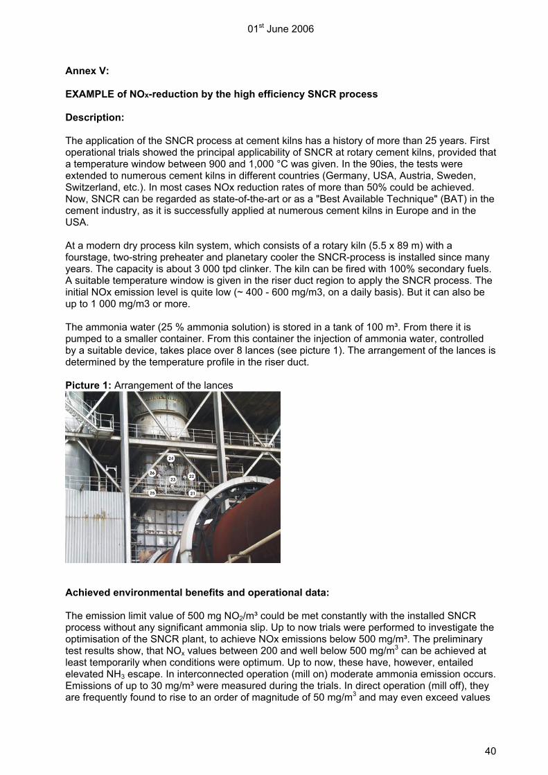
Annex V: EXAMPLE of NOx-reduction by the high efficiency SNCR process Description: The application of the SNCR process at cement kilns has a history of more than 25 years. First operational trials showed the principal applicability of SNCR at rotary cement kilns, provided that a temperature window between 900 and 1,000 °C was given. In the 90ies, the tests were extended to numerous cement kilns in different countries (Germany, USA, Austria, Sweden, Switzerland, etc.). In most cases NOx reduction rates of more than 50% could be achieved. Now, SNCR can be regarded as state-of-the-art or as a "Best Available Technique" (BAT) in the cement industry, as it is successfully applied at numerous cement kilns in Europe and in the USA. At a modern dry process kiln system, which consists of a rotary kiln (5.5 x 89 m) with a fourstage, two-string preheater and planetary cooler the SNCR-process is installed since many years. The capacity is about 3 000 tpd clinker. The kiln can be fired with 100% secondary fuels. A suitable temperature window is given in the riser duct region to apply the SNCR process. The initial NOx emission level is quite low (~ 400 - 600 mg/m3, on a daily basis). But it can also be up to 1 000 mg/m3 or more. The ammonia water (25 % ammonia solution) is stored in a tank of 100 m³. From there it is pumped to a smaller container. From this container the injection of ammonia water, controlled by a suitable device, takes place over 8 lances (see picture 1). The arrangement of the lances is determined by the temperature profile in the riser duct. Picture 1: Arrangement of the lances
Achieved environmental benefits and operational data: The emission limit value of 500 mg NO2/m³ could be met constantly with the installed SNCR process without any significant ammonia slip. Up to now trials were performed to investigate the optimisation of the SNCR plant, to achieve NOx emissions below 500 mg/m³. The preliminary test results show, that NOx values between 200 and well below 500 mg/m3 can be achieved at least temporarily when conditions were optimum. Up to now, these have, however, entailed elevated NH3 escape. In interconnected operation (mill on) moderate ammonia emission occurs. Emissions of up to 30 mg/m³ were measured during the trials. In direct operation (mill off), they are frequently found to rise to an order of magnitude of 50 mg/m3 and may even exceed values

01st June 2006
41
of 250 mg/m3 in individual cases. The NH3 escape, occurring therefore, sets limits to the over-stoichiometric addition of reducing agent. Applicability: Thus, the SNCR process was advanced to become “state of the art” in the cement industry over the past 10 years. When it is combined with primary measures, it allows to achieve good reduction rates at reasonable cost. More profound investigations on the optimisation of the SNCR-Technique in the mentioned example are currently being carried out. Economic efficiency: c.f cost estimation in the article “NOx Abatement”.

01st June 2006
42
Annex VI: Selective Catalytic Reduction (SCR)
Description Selective catalytic reduction (SCR) reduces NO and NO2 to N2 with the help of NH3 and a catalyst at a temperature range of about 300-400 °C. This technology is widely used for NOx abatement in other industries (coal fired power stations, waste incinerators). In the cement industry, basically two arrangements of the SCR reactor have to be considered: low dust configuration (between dedusting unit and stack) and high dust configuration (between preheater and dedusting unit). Low dust exhaust gas systems require re-heating of the exhaust gases after dedusting, which may cause additional energy costs and pressure losses. High dust systems do not require re-heating, because the waste gas temperature at the outlet of the preheater system is usually in the right temperature range for SCR operation. But the high dust levels (100 to 200 g/Nm3) impose high demands on the durability and the operation of the catalyst. Until now, only high dust systems have been tested in the cement industry. For high dust systems, a lot of attention has to be paid on the design and the chemical composition of the catalyst. Catalysts designed for low dust operation in other industries might not be suitable for high dust operation in a cement plant. High dust operation of an SCR reactor requires a high mechanical durability of the catalyst, a wider pitch than usual for low dust operation and an integrated dedusting system, in order to avoid plugging and activity losses. The appropriate chemical composition of the catalyst has to be evaluated by trials with high dust off-gases of cement kilns. The first full-scale SCR demonstration plant was built in Germany with governmental financial support. This plant (Solnhofer Portland-Zementwerke) is in operation since 2001. Solnhofer Portland-Zementwerke decided to implement a high dust SCR system because of the following reasons [Sauter/Samant, 2003]: • Lower consumption of NH3 in comparison to SNCR, resulting in lower operational costs • At the top of the four-stage preheater the waste gas has a temperature of 320–350 °C that is
suitable for SCR and does not require re-heating (as in the case of configuration between fabric filter and stack), thus reducing energy costs and pressure loss.
The SCR reactor in Solnhofen allows the installation of 6 layers of catalytic elements, while only 3 of these layers have been in use. A layer consists of 6 modules, each with 72 catalytic elements. The catalytic elements have a size of 15x15x90 cm each, a comb-like structure and a special composition based on TiO2 and V2O5. A pitch of 13 mm (10 mm in the middle layer) was chosen in order to avoid plugging. The integrated dedusting system uses preheated, high-pressurized air to remove dust accumulations from the catalyst surface. The air nozzles are moved continuously over each catalyst layer, thus no service interruption is necessary to remove dust from the catalyst. By optimisation of the dedusting system, the consumption of high-pressurized air was reduced from initially 100 m3/t to 18 m3 per ton of cement clinker, resulting in energy costs for the operation of the catalyst of about 0.098 € per ton of cement clinker [Sauter, 2006].

01st June 2006
43
Figure 1 Flow diagram of the SCR demonstration plant at Solnhofer Portland-Zementwerk In order to ensure a maximum lifetime of the SCR reactor, it was designed to facilitate either upstream or downstream operation (see Figure 1). Accordingly, the integrated dedusting system is able to blow away dust accumulations either from the upper or the lower surface of each catalyst layer. As long-term experience in Solnhofen did not prove expected advantages for upstream operation, there is no need for switching the gas flow direction. Accordingly, future implementations of high dust SCR could be designed for downstream operation only, thus reducing investment costs. The reduction agent, a water solution with 25% NH3, is added to the off-gas at the upper stages of the preheater in a molar ratio of 0.8 to 0.9 to the stoichiometric demand, according to the waste gas flow, the initial NOx concentration and the target value. The first set of catalysts was in operation for 40.000 h without excessive use or loss of activity. Later trials with plate-type catalysts showed higher mechanical use and unexpected losses of activity. In order to ensure full-time ELV compliance, the Solnhofen plant was equipped with an SNCR system for backup operation in 2006. At the moment only the SNCR- technique is operated at the kiln for comparison of operational costs with the SCR. Operational data / Achieved environmental benefits The NOx abatement efficiency of the SCR plant in Solnhofen usually is in the range of 59% to 67%. Under unusual operating conditions with raw gas concentrations of 3000 mg/Nm3 and higher, NOx abatement efficiencies of more than 80% were observed. In regular operation, the SCR reduces NOx emissions from raw gas concentrations of 1000 to 1600 mg/Nm3 to about 400 to 550 mg/Nm3. It has to be noted that the Solnhofen plant was designed to comply with a NOx emission limit value of 500 mg/Nm3 and that it has been operated accordingly, but sometimes the emission limit value of 500 mg/m3 was exceeded. With a molar ratio of 0.8 to 0.9, the consumption of NH3 is significantly lower than by application of SNCR. It has to be noted that NH3 from the raw material also serves as reduction agent in the reactor, thus the emission level of residual NH3 is very low. At Solnhofen, the SCR usually led to NH3 emissions below 1 mg/Nm3.

01st June 2006
44
In one campaign the NH3 dosage was increased according to a target NOx level of 200 mg/Nm3. In this campaign an emission level of around 300 mg/Nm3 was achieved. These results may indicate the potential of the technique, especially as they were also achieved with 3 catalytic layers only, and the emission level of residual NH3 was still around 1 mg/Nm3. Cross-media effects The only negative cross-media effect is a minor increase of electrical energy demand due to the internal dedusting system of the SCR reactor and additional pressure losses. Applicability Up to now SCR has only been tested on preheater and semi-dry (Lepol) kiln systems, but it might be applicable to other kiln systems as well. Economics The total investment costs of the SCR project in Solnhofen were about 3.5 million €, including extra expenditures for development reasons such as the capacity for 6 catalyst layers and the ability to operate either in upstream or in downstream mode. The investment cost of a new plant based on the Solnhofen experience are estimated to approximately 2.2 million for the SCR reactor, including ca. 250,000 € for the catalyst (to be calculated as replacement costs each 5–6 years). This amount does not include costs for ammonia storage and ductwork, as they vary significantly from site to site. In the costs for NOx reduction by SCR or by SNCR are estimated by the German federal environmental agency (UBA) for a kiln capacity of 1,500 t/d and a NOx reduction from 1,000 to 500 mg/Nm3 based on practical experience from the Solnhofen plant. In the last two columns the cost estimations are extrapolated for a NOx reduction to 200 mg/Nm3. As a result of the UBA calculations, the operating costs for SNCR and SCR – including replacement costs for the catalyst – are roughly the same for a target NOx level of 500 mg/Nm3, while the total specific costs for SCR are approximately 50% higher than for SNCR. At a target NOx level of 200 mg/Nm3, SCR seems to be more efficient regarding operating costs, but the total specific costs are still in the same level of magnitude than for SNCR. When comparing these figures, it has to be noted that long-term experience with a NOx level of 200 mg/Nm3 is neither available for SCR nor for SNCR yet. In the case of SNCR, higher emissions of NH3 also have to be taken into account. Table 1 : UBA cost comparison for NOx abatement by SCR vers. SNCR at a 1.500 t/d cement plant Basic assumptions Unit Klinker production rate t/a 480,000 t/d 1,500 Operation time h/a 7,680 Waste gas flow Nm3/t 2,300 Initial NOx level mg/Nm3 1,000 kg/t 2.3 NH3 price (25% solution) €/t 90.00 Catalyst price €/m3 7,500 Useful life of catalyst H 40,000 Useful life of investments A 20 Hurdle/inflation rate % 3.0%

01st June 2006
45
NOx abatement system SNCR SCR SNCR SCR NOx target value mg/Nm3 500 500 200 200 NH3 equivalent Kg/t 0.44 0.44 0.71 0.71 Stoichiometric factor 1.7 0.8 2.5 1.0 NH3(25%) consumption Kg/t 3.02 1.42 7.11 2.84 Kg/d 4,550 2,150 10,650 4,250 No. of catalytic layers 3 4 Catalyst volume M3 33.6 44.8 Operating costs NH3 consumption €/t 0.27 € 0.13 € 0.64 € 0.26 € Electric energy consumption €/t 0.03 € 0.10 € 0.06 € 0.11 € Catalyst replacement costs €/t 0.10 € 0.13 € Total operating costs €/t 0.30 € 0.33 € 0.70 € 0.50 €
Investment costs Ammonia system € 600,000 250,000 1,000,000 350,000 SCR reactor (except catalyst) € 1,950,000 2,350,000 Total investment € 600,000 2,200,000 1,000,000 2,700,000 Specific investment costs €/t 0.08 € 0.30 € 0.14 € 0.37 €
Total specific costs €/t 0.38 € 0.62 € 0.83 € 0.87 € NOx abatement costs €/t NOx 330.00 € 540.00 € 450.00 € 470.00 € A cost calculation of the German cement industry (VDZ) comprises a detailed approach concerning the costs of SCR technique [Scur, 2006]. Besides the investment costs this study considers also the whole operating costs including the costs for ammonia water, power consumption due to compressed air for the cleaning of the catalyst and the pressure drop due to the catalyst itself along with other cement plant typical economic assessment figures. Here it was shown that the costs for SNCR are always lower than those of SCR if European energy and NH3 prices are used as a basis. Theoretically, SCR could only become less costly than SNCR at very high reduction rates, if NH3 prices would rise extremely and energy prices would decrease. This situation however seems not be applicable for the EU region, since ammonia and energy costs are not opposing each other, as they tend to rise and concurrently fall. It could also be shown that efforts to reduce NOx by primary measures (~ 800 mg/m³ as average now in Germany) brought about better economics for SNCR, which costs are largely influenced by the costs for ammonia. The SCR results have shown a cost level of 1.25 to 2.00 €/t, depending on plant size and NOx removal efficiency required. The SCR is, in contrast to SNCR, dominated by the investment costs, which are 4 to 9 times higher than for a SNCR system. Furthermore the energy consumption is essentially due to pressure drop and cleaning air for the catalyst. The latest specific figures for the SCR system are reflecting the development of the technology. As an earlier VDZ study stated 3 €/t cli. as specific costs of the SCR, this value figure has now declined to around 1.75 €/t. Costs calculated by VDZ for a full scale installation (kiln capacity 1500 t cli./d, initial emissions of 1200 mg/m3 and a final level of 200, 500 and 800 mg/m3) is shown in table 2
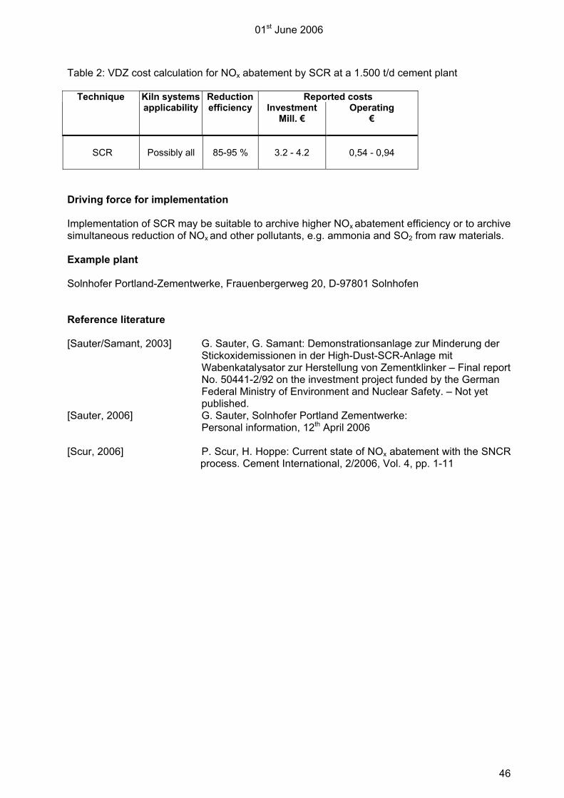
01st June 2006
46
Table 2: VDZ cost calculation for NOx abatement by SCR at a 1.500 t/d cement plant
Kiln systems Reduction Reported costs Technique applicability efficiency Investment
Mill. € Operating
€
SCR Possibly all 85-95 % 3.2 - 4.2
0,54 - 0,94
Driving force for implementation Implementation of SCR may be suitable to archive higher NOx abatement efficiency or to archive simultaneous reduction of NOx and other pollutants, e.g. ammonia and SO2 from raw materials. Example plant Solnhofer Portland-Zementwerke, Frauenbergerweg 20, D-97801 Solnhofen Reference literature [Sauter/Samant, 2003] G. Sauter, G. Samant: Demonstrationsanlage zur Minderung der
Stickoxidemissionen in der High-Dust-SCR-Anlage mit Wabenkatalysator zur Herstellung von Zementklinker – Final report No. 50441-2/92 on the investment project funded by the German Federal Ministry of Environment and Nuclear Safety. – Not yet published.
[Sauter, 2006] G. Sauter, Solnhofer Portland Zementwerke: Personal information, 12th April 2006
[Scur, 2006] P. Scur, H. Hoppe: Current state of NOx abatement with the SNCR
process. Cement International, 2/2006, Vol. 4, pp. 1-11
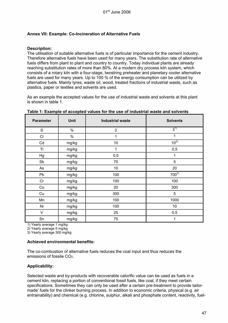
01st June 2006
47
Annex VII: Example: Co-Incineration of Alternative Fuels Description: The utilisation of suitable alternative fuels is of particular importance for the cement industry. Therefore alternative fuels have been used for many years. The substitution rate of alternative fuels differs from plant to plant and country to country. Today individual plants are already reaching substitution rates of more than 80%. At a modern dry process kiln system, which consists of a rotary kiln with a four-stage, twostring preheater and planetary cooler alternative fuels are used for many years. Up to 100 % of the energy consumption can be utilized by alternative fuels. Mainly tyres, waste oil, wood, treated fractions of industrial waste, such as plastics, paper or textiles and solvents are used. As an example the accepted values for the use of industrial waste and solvents at this plant is shown in table 1. Table 1: Example of accepted values for the use of industrial waste and solvents
Parameter Unit Industrial waste Solvents
S % 2 31)
Cl % 1 1
Cd mg/kg 10 102) Tl mg/kg 1 0,5 Hg mg/kg 0,5 1 Sb mg/kg 75 5 As mg/kg 10 20
Pb mg/kg 100 7003) Cr mg/kg 100 100 Co mg/kg 20 300 Cu mg/kg 300 5 Mn mg/kg 100 1000 Ni mg/kg 100 10 V mg/kg 25 0,5 Sn mg/kg 75 1
1) Yearly average 1 mg/kg 2) Yearly average 5 mg/kg 3) Yearly average 300 mg/kg Achieved environmental benefits: The co-combustion of alternative fuels reduces the coal input and thus reduces the emissions of fossile CO2. Applicability: Selected waste and by-products with recoverable calorific value can be used as fuels in a cement kiln, replacing a portion of conventional fossil fuels, like coal, if they meet certain specifications. Sometimes they can only be used after a certain pre-treatment to provide tailor-made’ fuels for the clinker burning process. In addition to economic criteria, physical (e.g. air entrainability) and chemical (e.g. chlorine, sulphur, alkali and phosphate content, reactivity, fuel-

01st June 2006
48
nitrogen content and heavy metal content) criteria play a decisive role in the selection of alternative fuels as they may have an impact on kiln operation and emissions, respectively. Operational data: In the following sheets the conditions and the result of the yearly emission monitoring is shown for the kiln mentioned before. During the measurement alternative fuels accounted for more than 80% of the energy input (see table 2). From table 3 it becomes clear that the strict emission levels can be met. Table 2: Operation data of the kiln (average of the data over a period of 3 days) Day Units 1 2 3
Time 08:00 – 18:00 08:00 – 18:00 08:00 – 18:00
Fossil fuels Main firing (coal dust) t/h 2.9 3.3 2.4
Alternative fuels
tyres t/h 3.4 3.4 3.4
Solvents – line 1 t/h 3.0 3.0 3.0
Solvents line 2 t/h 3.0 3.0 3.0
Plastics/wood t/h 6.3 6.3 6.3
Kiln input
Raw meal t/h 200 200 200
Calorific values
coal MJ/kg 26.8 26.8 26.8
tyres MJ/kg 26.0 26.0 26.0
Solvents – line 1 MJ/kg 27.7 27.7 27.7
Solvents line 2 MJ/kg 26.6 26.6 26.6
Plastics/wood MJ/kg 19.0 19.0 19.0
% of energy consumption
coal % 17 19 15
tyres % 20 19 20
Solvents – line 1 % 19 18 19
Solvents line 2 % 18 17 18
Plastics/wood % 27 28 27
Sum of alternative fuels % 83 81 85
total % 100 100 100
product
clinker t/h 121 121 121
capacity % 97% 97% 97%

01st June 2006
49
Table 3: Results of the emission monitoring during the combustion of alternative fuels
Results (1) Emission limit value
Mill on Mill off Components
Units average average
Temperature °C 106 151 ---
Humidity Vol.-% 17 17 ---
Volume flow m3/h 275.900 239.100 ---
Dust mg/m3 3 (2) 10 (3)
NOx mg/m3 385 (2) 500 (3)
SOx mg/m3 18 (2) 50 (3)
HCl mg/m3 n.d. (4) n.d. 10 (5)
HF mg/m3 0.09 (5) 0.06 (5) 1 (5)
Hg mg/m3 0,009 (5) < 0,01 (2)
0.033 (5) < 0,02 (2)
0.03 (mill on) / 0.05 (mill off) (3)
Σ (Cd, Tl) mg/m3 n.d. n.d. 0.03 (5)
Σ (Sb, As, Pb, Cr, Co, Cu, Mn, Ni, V, Sn) mg/m3 0.055 (5) 0.071 (5) 0.3 (5)
Σ (As, Benzo-a-pyren, Cd, Co, Cr) mg/m3 n.d. n.d. 0.05 (5)
TOC mg/m3 8 9 ---
PCDD/F ng-ITE/m3 n.d. n.d. 0,1 (6)
Benzene mg/m3 < 1 (5) 5 (5) (1) at 1 013 hPa and 273 K; after substraction of water content and an oxygen content in the flue gas of 10 Vol.-%. The limit values refer to the individual sampling periods as they are given in the respective standards. (2) yearly mean value as results of continuous measurements (3) daily mean value (4) n.d.: not detected (5) mean value for sampling peroid of 0,5 h (6) mean value for sampling peroid of 6 h Economic efficiency: Energy use typically accounts for 30-40% of the production costs. The costs of fuel are therefore a significant part of the costs of manufacturing cement. Waste fuels may be less expensive than primary fossil fuels although costs will vary with the type of waste and local conditions. Against these lower fuel costs alternative fuels and materials must frequently be pre-treated and made sufficiently homogeneous to be used in a cement kiln. Some additional environmental equipment may also be installed to control emissions. Special control and process measures may be needed to maintain safety, quality, and environmental standards. Driving force for implementation: The enormous cost pressure the cement industry is facing has led to a continual rise in the utilisation of alternative fuels over the past years.The selection of alternative fuels and materials is driven by a number of interrelated considerations, including the following main points: − Reduction of fossil CO2 emissions − Reduction of the use of natural resources − Impact on fuel cost


![Pegasus Atlas - Naxertech Ltd · Lahore-Islamabad Motorway, Sheikhupura. 7029-LES-12] Sufyan KWh Ibraheem e V3GÁ 2:56 PM KWh 122 days KWh 31 days 5 KWh 6 hours KWh 1 hours KWh 1](https://img.dokumen.tips/doc/110x75/5f805ee113da62458911841f/pegasus-atlas-naxertech-lahore-islamabad-motorway-sheikhupura-7029-les-12-sufyan.jpg)