Embed Size (px)
Citation preview

Gerard Installation ManualShingle Profiles
February 2014
Guardian Shingle
Granite Ridge Shingle

Shingle Installation Manual
Gerard Roofing TM2
Please Note: It is the responsibility of the installer to adhere to local building codes.
This Installation Manual is designed as an instructional tool to clearly depict to the contractor, installer, distributor and architect, recommended installation techniques and procedures to confidently estimate and install a Granite Ridge and Guardian Shingle roofing system by Gerard Roofing Technologies.
This manual depicts generally practiced application techniques only, which should not be sub-stituted for local building code specifications. Gerard Roofing Technologies carries product app -roval reports for most building code agencies in North America which should be referenced for specific local requirements. See Gerard’s website for further information.
These methods have been developed by Gerard Roofing as proven acceptable and tested methods of installing Gerard Stone Coated Steel Roofing. Gerard Roofing does not construe that these are the only methods but again are the tried and true proven techniques that are currently practiced by the majority of trained installers.
This manual emphasizes common roofing practices in use today. If application techniques vary from those illustrated in this manual or if using this manual for applications not covered, please consult the technical department at 1-800-237-6637.
As Gerard Roofing Technologies have no control over the installation techniques used, no warranty can be made relating to the installation of Gerard products.
Product Approval Reports for various areas are available which should be analyzed for additional proce-dures after careful review of this manual.
A careful study of this manual will give a full comprehension of a Granite Ridge and Guardian Shingle roof installation.
Gerard Roofing assumes no liability for either incorrect installation of its products or personal in-jury that may occur as a result of installing such products. The installation methods demonstrated in these materials are not the only ways to install Gerard products, but have been developed as a reference guide using acceptable, tested and proven methods for the standard installation of Ge-rard products. Contractors and installers should at all times use their professional judgment, and modify and tailor such methods where appropriate or necessary to suit each specific installation or any applicable local building codes or ordinances. Due to the fact that Gerard has no control over the actual installation techniques used, no warranty is expressed or implied relating to instal-lation of the product. Gerard’s liability with respect to Gerard products is limited exclusively to its standard written limited lifetime warranty.
Shingle Installation Manual
3 Gerard Roofing TM
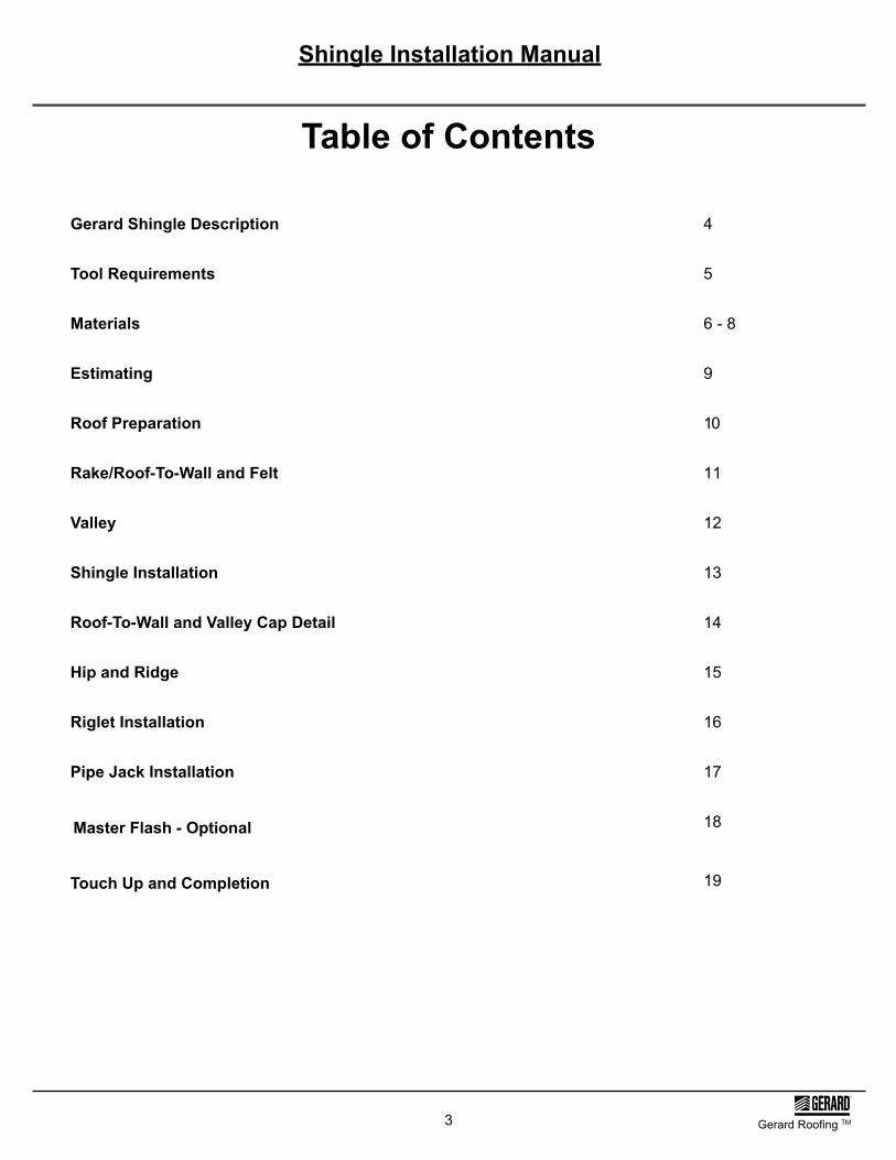
Gerard Shingle Description 4
Tool Requirements 5
Materials 6 - 8
Estimating 9
Roof Preparation 10
Rake/Roof-To-Wall and Felt 11
Valley 12
Shingle Installation 13
Roof-To-Wall and Valley Cap Detail 14
Hip and Ridge 15
Riglet Installation 16
Pipe Jack Installation 17
Touch Up and Completion
18
Table of Contents
Master Flash - Optional
19

Shingle Installation Manual
Gerard Roofing TM4
Actual ExposureCoverageAverage weight per shingle Average weight per square
46 1/6” x 15 5/8”44” x 13 11/16”24 shingles per square 5 lbs120 lbs
Gerard Shingle Description
15 5/8”
13 11/16”
15 5/8”
13 11/16”
Guardian Shingle
Granite Ridge Shingle
Roof Pitch 4:12 minimum

5
- Standard claw hammer
- 50’ or 100’ tape measure
- Screw drivers (optional power drive)
- Utility knife (when re-roofing over composition shingle)
- Tin snips
Tool Requirements
List of Tools Required:
- Caulking gun- Chalk line- One pair of needle-nose pliers
Gerard Tile Cutter- creates neater, straighter cuts
The Tru-Cut Shear is reversible for left-handed or right-handed use.Assembly shown here is for right-handed use. Simply reverse assemblyfor left-handed use.
Replacement Handle Grip
Replacement Top Blade
Replacement Bottom Blade
Shingle Installation Manual
Gerard Roofing TM

Shingle Installation Manual
6 Gerard Roofing TM
Valley CapStone Coated120” Length
ValleyNon-Stone Coated120” Length
RigletNon-Stone Coated120” Length
Rake/Roof to WallNon-Stone Coated120” Length
Materials
Granite Ridge ShingleStone Coated24 pcs. / sq.
Guardian ShingleStone Coated24 pcs. / sq.
Char Filter Foam (Under Valley Cap)Non-Stone Coated3/4” x 4-1/2“ x 118” Length

Shingle Installation Manual
Gerard Roofing TM7
Rake CoverStone Coated120” Length
Starter StripStone Coated120” Length
110˚ Head MetalStone Coated120” Length
Hip and Ridge CapStone Coated14” Length
Pipe Jack Tray (Cut centre hole on site)Non-Stone Coated14” x 14”
Materials
Rake/Roof to Wall Pce.
Z-Bar Attachment (Roof to Wall)Stone Coated120” (10 ft.) Lengths
Pipe Jack Flashing:Part no: See Inside SalesCoated or Non-coated
Rake/Roof to Wall Pce.

Shingle Installation Manual
8 Gerard Roofing TM
Super flexibleProfessional thermoplastic sealantSuper flexibleScellant thermoplastique profesional
Guardian Shingle
Granite Ridge Shingle
30 # Felt
Ring Shank Roofing Nails: 1-1/4” minimumSufficient length to penetrate sheathing per code (min. of 1/2”)
* In high wind regions refer to local building codes and manufacturer applicableproduct evaluation reports.
Stitch Screw for Valley Cap Only: #8 x 1/2”
SealantNP1 or equal
Finishing Kit / Touch UpComprises of 8 oz. squeeze bottle of base and 3 lbs. of color stone chosen.
Materials
Panel Fasteners:(Installing contractor responsible to check local code requirements for type of fastener).
Screws: #8 x 1-1/4” (Higher wind load regions)
E Z Vent for Shingles:Ventilation Option for high wind regions

Shingle Installation Manual
Gerard Roofing TM9
Overall Fascia Length 50’
Rafter Length 18’
Hip Length 21’
How to Determine How Much Material You Will Need
Quick Step Method, USA Standard(approximate)
1. Determine roof square foot feet without waste.2. Add linear feet of hips and valleys. Multiply by 2.3. Add totals from steps 1 and 2.4. Multiply total by 1.03. This yields roof square feet including waste.5. Divide total from step 4 by 100. This yields roof squares. Gerard Shingle is 24 panels per square.
1) 50 X 36 = 1800 s/f w/o waste2) Hip x 4 = 84 x 2 = 168 linear feet3) 168 + 1800 = 19684) 1968 x 1.03 = 20275) 2027 ÷ 100 = 20.27 sqs
Estimating
Shingle Installation Manual
10 Gerard Roofing TM
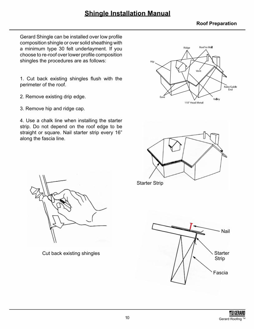
Gerard Shingle can be installed over low profile composition shingle or over solid sheathing with a minimum type 30 felt underlayment. If you choose to re-roof over lower profile composition shingles the procedures are as follows:
1. Cut back existing shingles flush with the perimeter of the roof.
2. Remove existing drip edge.
3. Remove hip and ridge cap.
4. Use a chalk line when installing the starter strip. Do not depend on the roof edge to be straight or square. Nail starter strip every 16” along the fascia line.
Cut back existing shingles
Nail
StarterStrip
Fascia
Starter Strip
Roof Preparation

Shingle Installation Manual
Gerard Roofing TM11
5. Lay one layer of 30 lb. felt up the valley. If you live in an area where ice damming occurs, use ice and water shield. Cover the entire roof with a minimum of #30 felt. At the valleys weave the opposing courses of underlayment.
6. Install the uncoated rake roof to wall up the gable or rake, fastening it where shown. It is sometimes easier to assemble the rake cover on to the rake roof to wall before installing. When done this way, shorten the first (bottom piece) of rake cover in order to prevent all the ends from lining up. Head lap is necessary for
the rake roof to wall (approx 3”). The rake cover should be notched at the top flange in order to achieve side lap 1 - 1 1/2” is sufficient.
Rake/Roof-To-Wall and Felt
RAKE COVER
FASTEN RAKE COVER HERE & AS NEEDED
RAKE OR GABLE END
7. Ensure that the bottom end of the rake roof to wall overlaps the top flange of the starter strip and extends to or slightly beyond the loweredge of the starter strip. Place sealant betweenthe lower edge of the rake roof to wall and thestarter strip.

Shingle Installation Manual
12 Gerard Roofing TM
Valley
Ensure that the full width of the valley overlaps the top flange of the starter strip and extends slightlybeyond the lower edge of the starter strip. Place sealant between the lower edge of the valley andthe starter strip. Trim lower edge of the valley as needed.
Fasten and seal in outer channel
Place sealant
Shingle Installation Manual
Gerard Roofing TM13
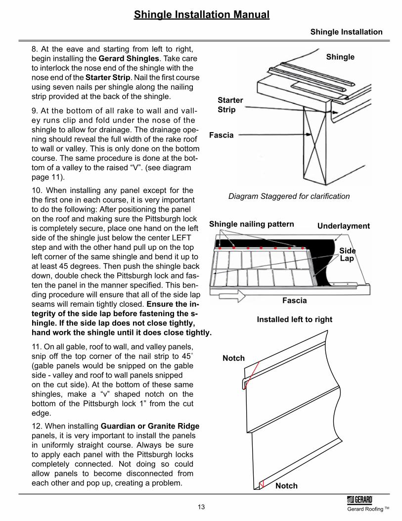
8. At the eave and starting from left to right, begin installing the Gerard Shingles. Take care to interlock the nose end of the shingle with the nose end of the Starter Strip. Nail the first course using seven nails per shingle along the nailing strip provided at the back of the shingle.
9. At the bottom of all rake to wall and vall-ey runs clip and fold under the nose of theshingle to allow for drainage. The drainage ope-ning should reveal the full width of the rake roofto wall or valley. This is only done on the bottomcourse. The same procedure is done at the bot-tom of a valley to the raised “V”. (see diagrampage 11).
10. When installing any panel except for thethe first one in each course, it is very importantto do the following: After positioning the panelon the roof and making sure the Pittsburgh lockis completely secure, place one hand on the leftside of the shingle just below the center LEFT step and with the other hand pull up on the topleft corner of the same shingle and bend it up toat least 45 degrees. Then push the shingle backdown, double check the Pittsburgh lock and fas-ten the panel in the manner specified. This ben-ding procedure will ensure that all of the side lapseams will remain tightly closed. Ensure the in-tegrity of the side lap before fastening the s-hingle. If the side lap does not close tightly,hand work the shingle until it does close tightly.
11. On all gable, roof to wall, and valley panels, snip off the top corner of the nail strip to 45˚ (gable panels would be snipped on the gable side - valley and roof to wall panels snipped on the cut side). At the bottom of these same shingles, make a “v” shaped notch on the bottom of the Pittsburgh lock 1” from the cut edge.12. When installing Guardian or Granite Ridge panels, it is very important to install the panels in uniformly straight course. Always be sure to apply each panel with the Pittsburgh locks completely connected. Not doing so could allow panels to become disconnected from each other and pop up, creating a problem.
Shingle
StarterStrip
Fascia
Diagram Staggered for clarification
Shingle nailing pattern Underlayment
SideLap
Fascia
Installed left to right
Shingle Installation
Notch
Notch
Shingle Installation Manual
14 Gerard Roofing TM
Shingle
Z-Bar AttachmentRake/Roof-To-Wall
110° Head Metal
Builder Installed Z-Bar
Builder Installed Z-Bar
Rake/Roof-to-Wall Rake/Roof-to-Wall 110° Head Metal110° Head Metal
Roof-To-Wall and Valley Cap Detail
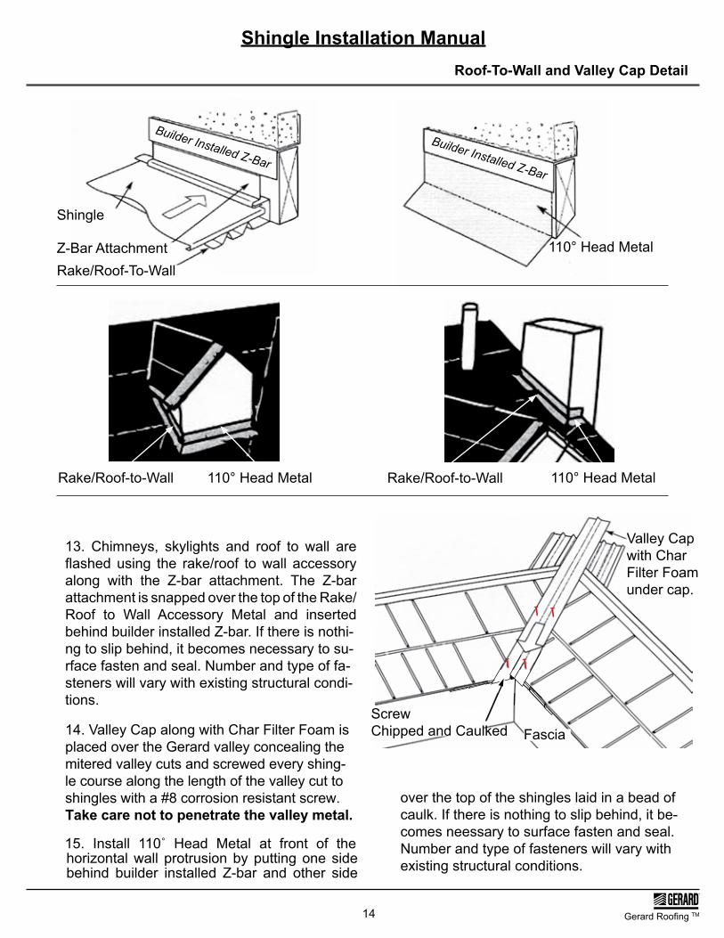
13. Chimneys, skylights and roof to wall are flashed using the rake/roof to wall accessory along with the Z-bar attachment. The Z-bar attachment is snapped over the top of the Rake/ Roof to Wall Accessory Metal and inserted behind builder installed Z-bar. If there is nothi-ng to slip behind, it becomes necessary to su-rface fasten and seal. Number and type of fa-steners will vary with existing structural condi-tions.
14. Valley Cap along with Char Filter Foam isplaced over the Gerard valley concealing themitered valley cuts and screwed every shing-le course along the length of the valley cut toshingles with a #8 corrosion resistant screw.Take care not to penetrate the valley metal.
15. Install 110˚ Head Metal at front of the horizontal wall protrusion by putting one side behind builder installed Z-bar and other side
over the top of the shingles laid in a bead of caulk. If there is nothing to slip behind, it be-comes neessary to surface fasten and seal.Number and type of fasteners will vary withexisting structural conditions.
Valley Capwith Char Filter Foamunder cap.
FasciaScrewChipped and Caulked

Shingle Installation Manual
Gerard Roofing TM15
16. The shingles above the eave course are installed by interlocking the nose end of the shingle with the back end (Pittsburgh lock) of the shingle of the preceding course concealing the nailing strip.
17. At the rake or gable end cut the shingles to fit and insert the cut edge into the rake/roof to wall.
18. Hip and Ridge shingles are mitered to fit nailed and covered using the Gerard Hip and Ridge accessory.
19. Before installing Hip and Ridge cap, placea strip of 5 to 6 inch wide Peel-N-Stick (hightemperature) atop the cut hip and ridge shingles.
Hip Cap
Mitre Cut
Screws - Seal and Chip
Hip and Ridge
NOTE: Ensure Peel-N-Stick not exposedafter cap installation.
Rake/Roof to Wall Accessory MetalShingle Rake Roof To Wall
Starter Strip
Notch area at bottom of gable or rake and fold under to allow fordrainage.
Ridge Cap
Optional Hip Detail: Left side panel cuts off at hip intersectionwith the right side panel overlapping overthe hip intersection and left panel byapproximately 2 inches.Note:This detail can also be used for “non-vented”ridge.
Optional Non-Vented Hip Detail
Screws - Seal and Chip

Shingle Installation Manual
16 Gerard Roofing TM
20. The Gerard Riglet is available for use with installations involving an offset at the eave. The Riglet is aligned with the offset, set in bed of caulk and nailed on the back apron every six inches. The shingles are then installed on the main roof interlocking with the nose end of the riglet and laying over the top of the shingle be-low.21. If you have difficulty closing some side laps, the following procedure is acceptable:
Apply a 1-1/2”, corrosion resistant hex head screw directly beneath the mid shelf of the shingle and approximately 3” to the right of the left side of the shingle.This screw is to be of sufficient length to pass completely through the roof sheathing. Do not over tighten or pen-etrate the overlapped shingle. Make absolutely certain you have followed the procedure out-lined on page 18 - Note 24.
Riglet -Set in a bead of NP1 or equal or butyl tape.
Fascia Starter Strip
Riglet Installation

Shingle Installation Manual
Gerard Roofing TM17
22.
Pipe Jack Tray
Sealant
Pipe Jack
Sealant - Seal and Chip
Pipe Jack Installation
22. Pipe Penetrations:Weep-Hole Notch
Pipe Jack Tray inter-
Pittsburgh lock.Pipe Jack is
is placed over
down onto the Pipe
may enter in or around the pipe penetration. A weep holeis created by making t wo vertical cuts at the shingle nose approxim-
ately 1” apart. Fold the 1” tab back under the shingle. Seal where indicated.
to protect against any future moisture thatJack Tray. Provide weep holes
the pipe and
locks with lower

Shingle Installation Manual
18
1.
2.
3.
4.
5.
Easy 5-Step InstallationMasterflash can be installed on-site quickly ∗ and easily, usually under 10 minutes.One piece construction makes Masterflash ∗ easy to handle.Bendable base forms seal with any contour, ∗ surface irregularities or roof pitch.Seals tightly and dependably with silicone seal-∗ ant to eliminate costly call-backs.Pipe opening is easily customized with a sharp ∗ knife or scissors for any application.Fix flashing to pipe with stainless steel hose ∗ clamp where snow load conditions exist.
1. Select and TrimChoose appropriate Masterflash with opening at least 20% smaller than pipe diameter. If necessary trim opening to 20% smaller than pipe diameter.
2. SlideSlide Masterflash down over pipe. (A non-petro -leum based lubricant will ease installation.)
3. FormPress Masterflash down, bending it to conform to roof profile or roof irregularities. A blunt tool will help press flashing into tight roof angles.
4. SealApply silicone sealant between base and roof.
5. FastenUse fasteners to complete sealing.
Master Flash - Option
Note:For further protection it is recommended toinstall Pipe Jack Tray per details page 17of Pipe Jack installation. Ensure sealing around roof pipe and Pipe Jack Trayprior to installing cover panel andMasterflash.
Gerard Roofing TM

Shingle Installation Manual
19 Gerard Roofing TM
23. Inspect the roof and touch-up all exposed screws using the provided touch-up kit. Remove all debris from roof and job-site.
24. Acceptable Repair Option
Touch Up and Completion
Side Lap
Screw
Corrosion Resistant ScrewMinimum 1 1/2” #8
Apply small bead of sealant between panels at side lap. Ensure sealant is not exposed out-side of sidelap.
Draw panels together
Do not over-tighten the screw fastener
Sealant
955 Columbia Street Brea, California 1-800-23ROOFS
1632 Third Street, Leesburg, Forida 1-866-919-7663
1100 Chase Road, Suite 100 Mesquite, Texas 1-866-295-9016
1115 Erie Street, Kansas City, Missouri 1-800-444-4503
Please Note: It is the responsibility of the installer to check the website for any updates or changes in the application of this product(s).
Gerard Roofing Technologies TM
E-mail: [email protected] Website: www.GerardUSA.com