Embed Size (px)
Citation preview


Geothermal Heat Pump Systems Manual

!"#$%&'($)*+,$-&.+*./"0$+&$122'"00$3'"".4&/0"$310$"5*00*&.0$1.2$410$"6-""2"2$1$789$'"2/-+*&.$&:"'$;<<=$>":">0?$@1,&'$A>&&5B"'3C0$D>1!%)$;<8<$15B*+*&/0$3&1>$&E$1$8<9$'"2/-+*&.$B,$;<8<F$4&#":"'F$#*>>$B"$-41>>".3"2$B,$G&G/>1+*&.$*.-'"10"0$1.2$/."6G"-+"2$-41.3"0$*.$->*51+"?$H"&+4"'51>$4"1+$G/5G0$-1.$G>1,$1$0/B0+1.+*1>$'&>"$*.$'"1-4*.3$+4*0$12:1.-"2$3&1>?
I*.-"'">,F
J1:*2$K?$A/'.",F$LMNM
David J. Burney, FAIACommissioner, New York City Department of Design and ConstructionJune 2012
Preface
I/0+1*.1B>"$J"0*3.$410$B"".$1$>"12"'$*.$2":">&G*.3$4*34$G"'E&'5*.3$B/*>+$".:*'&.5".+0$+41+$"5G410*O"$"."'3,P01:*.3$+"-4.&>&3*"0$0/-4$10$3"&+4"'51>$4"1+$G/5G0?
M0$1.$1>+"'.1+*:"$+&$-&0+>,F$-&.:".+*&.1>$"."'3,$0&/'-"0F$3"&+4"'51>$4"1+$G/5G0$/0"$&.0*+"$"."'3,$E'&5$/.2"'P3'&/.2$+"5G"'1+/'"$2*EE"'".+*1>0$+&$4"1+$1.2$-&&>$B/*>2*.30$#*+4$'"#1'2*.3$'"2/-+*&.0$*.$"."'3,$/0"$1.2$3'"".4&/0"$310$"5*00*&.0$+4'&/34&/+$+4"$>*E"$&E$1$B/*>2*.3?$M>+4&/34$G'1-+*-1>F$+4"$1GG>*-1+*&.$&E$+4"0"$0,0+"50$-1.$B"$-&5P
G/B>*04"2$*.$;<<;F$G'&:*2"0$1$-&5G'"4".0*:"$B1-(3'&/.2$&.$+4"$0/BQ"-+$1.2$122'"00"0$G&+".+*1>$-41>>".3"0$+41+$51,$1'*0"$2/'*.3$+4"$2"0*3.$1.2$-&.0+'/-+*&.$&E$+4*0$+"-4.&>&3,?$N.$122*+*&.F$*+$G'&:*2"0$G'&E"00*&.1>0$#*+4$$+4"$."-"001',$+&&>0$E&'$/.2"'0+1.2*.3$+4"$.1+/'"$&E$$!"#$%&'($)*+,C0$3"&>&3,$1.2$4&#$+41+$*.E&'51+*&.$-1.$$B"$/+*>*O"2$+&$*.+"3'1+"$3"&+4"'51>$4"1+$G/5G0$*.+&$$1$0/0+1*.1B>"$G'&Q"-+?
A Design and Installation Guide for New York City Projects

5 Construction
5.0 List of Abbreviations5.1 Construction5.2 Contractor Training and Certification5.3 Construction Logistics5.4 Regulatory Requirements5.5 GRCO Monitoring and Coordination5.6 GRCO Best Practices5.7 System Start-Up and Balancing5.8 Commissioning
6 Operation and Maintenance
6.0 List of Abbreviations6.1 Operations and Maintenance6.2 Operational Considerations 6.3 Maintenance
7 Case Studies
Brooklyn Children’s Museum Queens Botanical Garden Weeksville Heritage Center Lion House at the Bronx Zoo Staten Island Museum at Snug Harbor
Appendices
A Hydrogeology and Its Limiting Factors on GHP Systems
B Field TestingC Supplemental Regulatory RequirementsD Regulatory Agencies Contact Information
Requirements and ResourcesE Sample Specifications for Modular Water-
to-Air and Water-to-Water Heat PumpsF Sample of Pre-Functional Checklist
and Start-Up ChecklistG Selected Glossary and References
Contents
1 Introduction
1.0 List of Abbreviations1.1 Introduction 1.2 Advantages and Applications 1.3 Typical Workflow 1.4 Project Team Members 1.5 GHP Project Considerations 1.6 GHP Screening
2 Geothermal Heat Pump System Components
2.0 List of Abbreviations2.1 GHP System Components2.2 Geothermal Heat Pumps 2.3 Ground Couplings
3 Schematic Design
3.0 List of Abbreviations3.1 Schematic Design3.2 Geology and Hydrogeology3.3 Site Investigation 3.4 Feasibility Analysis
4 Design
4.0 List of Abbreviations4.1 GHP System Design4.2 Load Analysis and Sizing4.3 GHP Configurations4.4 Ratings and Performance4.5 Refrigerant Types4.6 Antifreeze Types4.7 Manifold System Design4.8 GRCO Design Considerations4.9 Hybrid Systems4.10 System Redundancy
008
009010016017020022023
118
119120121122126131133134136
168
168
178186192
198 215
230
156
158160162164166
138
139140142144
028
029030032038
060
061062063073078
092
093094095097103105106107110114116

Abbreviations Used Throughout Text
Geothermal Technology
AHU Air Handling Unit
BMS Building Management System
COP Coefficient of Performance
Cx Commissioning
DTB Depth to Bedrock
DTW Depth to Ground Water
EER Energy Efficiency Ratio
EWT Entering Water Temperature
FCU Fan Coil Unit
GHP Geothermal Heat Pump
GRCO Ground Coupling
HTF Heat Transfer Fluid
HVAC Heating, Ventilation, and Air Conditioning
HX Heat Exchanger
IRB Iron-Related Bacteria
O&M Operations and Maintenance
ODP Ozone Depletion Potential
SCW Standing Column Well
VFD Variable Frequency Drive
Organizations
ACCA Air Conditioning Contractors Association
AHRI Air Conditioning, Heating and Refrigeration Institute
ASHRAE American Society for Heating, Refrigerating and Air-conditioning Engineers
IGSHPA International Ground Source Heat Pump Association
Project Team Members
A Architect
CE Civil Engineer
CM Construction Manager
CxA Commissioning Agent
DC Drilling Contractor
EC Electrical Contractor
GC General Contractor
GEO Geologist/Hydrogeologist
GTE Geotechnical Engineer
GTH Geothermal Engineer
LEED Sustainability/LEED Consultant
MC Mechanical Contractor
MEP Mechanical, Electrical, and Plumbing Engineer
LEED Leadership in Energy and Environmental Design
MTA Metropolitan Transportation Authority
NGWA National Ground Water Association
NYCDDC New York City Department of Design and Construction
NYCDEP New York City Department of Environmental Protection
NYCDOB New York City Department of Buildings
NYCDOH New York City Department of Health
NYCDOT New York City Department of Transportation
NYSDEC New York State Department of Environmental Conservation
PANYNJ Port Authority of New York and New Jersey
UIC Underground Injection Control
USEPA U.S. Environmental Protection Agency
USGBC US Green Building Council
USGS United States Geological Survey

Geothermal Heat Pump Background / 09 08 / Geothermal Heat Pump Manual
Introduction
11.0List of Abbreviations
GHP
HX
BMS
SCW
COPGeothermal Heat Pump
Building Management System
Standing Column Well
Coefficient of Performance
GRCO HDPE HVACGround Coupling High-Density
PolyethyleneHeating, Ventilation, and Air Conditioning
Heat Exchanger

010 / Geothermal Heat Pump Manual Background for a Geothermal Heat Pump System Project / 011
Air return duct
Air return duct
Supply air duct
Heated or cooled air from ducts
Ground temperatures remain nearly constant at about 55°-65° year round
Geothermal heat pumpheats air in winter, extracts heat from air in summer
Ground couplingfluid circulator pump
Ground coupling transfers heat to ground in summer,and absorbs heat from graund in winter
Outdoor air temperaturescan vary widely throughoutthe year
General layout of a GHP systemFigure 1.1
GRCO
GHP
Simplified GHP System LayoutFigure 1.1 1.1
Introduction
N.$+4"$0"1'-4$E&'$'"."#1B>"$'"0&/'-"0F$3"&+4"'51>$"."'3,$R/*-(>,$"5"'3"0$10$1$->"1.$1.2$#*2">,$1:1*>1B>"$"."'3,$0&/'-"?$M>+4&/34$3"&+4"'51>$"."'3,$*0$E'"R/".+>,$100&-*1+"2$#*+4$">"-+'*-*+,$3"."'1+*&.$*.$+4"$#"0+"'.$S.*+"2$I+1+"0F$+4"'51>$"."'3,$1+$:1',*.3$2"G+40$-1.$B"$/0"2$*.$./5"'&/0$1GG>*-1+*&.0?$T4"$+,G"$&E$3"&+4"'51>$+"-4.&>&3,$+41+$*0$31*.*.3$1--"G+1.-"$*.$+4"$!"#$%&'($)*+,$1'"1$+1("0$12:1.+13"$&E$+4"$0+1B>"$+"5G"'1+/'"0$E&/.2$*.$+4"$3'&/.2$1.2$.1+/'1>$1R/*E"'0$E&'$4"1+*.3$$1.2$-&&>*.3$B/*>2*.30?$
Geothermal heat pump$ GHP $0,0+"50$1'"$1$3'&#*.3$0"-+&'$*.$+4"$0G1-"$-&.2*+*&.*.3$51'("+$10$"."'3,$
$&G"'1+*&.0?$HUD0$41:"$B"".$0/--"00E/>>,$&G"'1+"2$E&'$2"-12"0$*.$:*'+/1>>,$":"',$B/*>2*.3$+,G"$E&'$B&+4$4"1+*.3$1.2$-&&>*.3?$U&#":"'F$#*+4*.$!"#$%&'($)*+,F$HUD$/0"$*0$'">1+*:">,$."#?$M>+4&/34$1$+,G"$&E$HUD$0,0+"5$-1>>"2$+4"$&G".$>&&G$410$B"".$/0"2$E&'$1*'$-&.2*+*&.*.3$10$#">>$10$*.2/0+'*1>$G'&-"00$#1+"'$E&'$$
$0,0+"50$E&'$0G1-"$-&.2*+*&.*.3$&.>,$B"-15"$&G"'1+*&.1>$
P51.-"$B/*>2*.3$51.21+"F$+4"$New York City Department of Design and Construction$ NYCDDC13".-,$+&$*.:"0+*31+"$1.2$*.-&'G&'1+"$HUD$$+"-4.&>&3,$*.+&$*+0$G'&Q"-+0?$
T4"$G'*51',$2*EE"'".-"$B"+#"".$1$HUD$0,0+"5$1.2$$1$-&.:".+*&.1>$heating, ventilation and air conditioning HVAC $0,0+"5F$*0$+4"$-&5B*.1+*&.$&E$+#&$2*0+*.-+$-&5G&P.".+0F$+4"$HUD$*.0+1>>"2$#*+4*.$+4"$B/*>2*.3$1.2$+4"$ground coupling GRCO $*.0+1>>"2$&/+2&&'0?$V4*>"$+4"$5"-41.*-1>$G*G*.3$1.2$2/-+#&'($1'"$+4"$015"$*.$B&+4$0,0+"5$+,G"0F$+4"$HUD$0,0+"5$"00".+*1>>,$-&/G>"0$$+4"$B/*>2*.3C0$4"1+$G/5G$#*+4$+4"$3'&/.2$0"':*.3$10$$
$0,0+"5$>1,&/+$*0$*>>/0+'1+"2$*.$ Figure 1.1 ?
H'&/.2$+"5G"'1+/'"0$E&'$#">>0$2'*>>"2$+4'&/34&/+$$!"#$%&'($)*+,$'1.3"$E'&5$==WX=$°LF$#4*-4$*0$$1>'"12,$->&0"$+&$2"0*3.$+"5G"'1+/'"0$E&'$0G1-"$$-&.2*+*&.*.3?$N.$+4"$4"1+$G/5G$0,0+"50F$+4"$coefficient of performance$ COP $*5G'&:"0$10$+4"$+"5G"'1+/'"$2*EE"'".+*1>$*0$5*.*5*O"2F$*.2*-1+*.3$1.$*.-'"10"$*.$
"."'3,$+&$G'&:*2"$+4"$015"$4"1+*.3$1.2$-&&>*.3$+41.$-&.:".+*&.1>$1*'$&'$#1+"'$B10"2$UYM)$"R/*G5".+?$$V*+4$"."'3,$-&0+0$-&.+*./*.3$+&$'*0"F$HUD$0,0+"50$B"-&5"$1$->"1'$-4&*-"$*.$4">G*.3$+&$'"2/-"$"."'3,$-&.0/5G+*&.$*.$B/*>2*.3$&G"'1+*&.0?$
012 / Geothermal Heat Pump Manual Background for a Geothermal Heat Pump System Project / 013
From Bldg
To Bldg
500 Ft. (Max)
500 Ft. (Max)
loops can also be installed into bedrock
loops
Land over loop field available for other uses
headers (5-loop circuit shown)
Bedrock
Unconsolidated Deposits
Ground Water Level
High Density Polyethylene Piping
HDPE
HDPE
HDPE
HDPE
UD
UDBR
BR
Closed Looped SystemFigure 1.2.1 Introduction
Overview of ComponentsHUD0$1'"$1$+,G"$&E$4"1+$G/5G$+41+$/0"0$+4"$ GRCO $+&$+'1.0E"'$4"1+$"."'3,$+&$1.2$E'&5$+4"$3'&/.2?$T4"$/.*+0$-1.$B"$*.0+1>>"2$1.2$-&.."-+"2$+&$2*0+'*B/+*&.$0,0+"50$*.$+4"$015"$51.."'$10$#1+"'P+&P#1+"'$&'$#1+"'P+&P1*'$4"1+$G/5G0?$M.$122*+*&.1>$2":*-"$-1>>"2$1$2"P0/G"'4"1+"'$$-1.$B"$*.+"3'1+"2$+&$4"1+$2&5"0+*-$4&+$#1+"'$#*+4$#10+"$4"1+$.&'51>>,$'"Q"-+"2$B1-($*.+&$+4"$3'&/.2?$
T4"$+4'""$G'*51',$+,G"0$&E$HZ)[C0$"5G>&,"2$*.$$!"#$%&'($)*+,$1'"$&G".$>&&GF$->&0"2$>&&G$1.2$standing column wells$ SCW ?$J"G".2*.3$&.$+4"$0*+"C0$3"&>&3,$$1.2$&+4"'$0/B0/'E1-"$-&.2*+*&.0F$+4"$HZ)[$-1.$B"$$1$0"'*"0$&E$#">>0$&'$G>10+*-$G*G"0$3'&/+"2$*.$B&'"4&>"0?$J"0G*+"$-&.0+'/-+*&.$2*EE"'".-"0F$1>>$HZ)[0$/0"$1$-*'-/>1+*.3$>*R/*2F$"*+4"'$3'&/.2$#1+"'$&'$1.$1.+*PE'""O"$0&>/+*&.$*.$->&0"2$G*G*.3F$+&$+'1.0E"'$4"1+$"."'3,$$B"+#"".$+4"$B/*>2*.3$1.2$+4"$3'&/.2?$
)>&0"2$>&&G$0,0+"50F$ Figure 1.2.1 F$-*'-/>1+"$#1+"'$$#*+4$1.$1.+*E'""O"$0&>/+*&.$*.$1$."+#&'($&E$->&0"2$$G*G*.3$*.0+1>>"2$*.$+4"$3'&/.2?$[G".$>&&G$0,0+"50F$$Figure 1.2.2 F$/0"$3'&/.2$#1+"'$G/5G"2$E'&5$1$0/GG>,$#">>$+&$+'1.0E"'$4"1+$1.2$'"+/'.0$+4"$#1+"'$B1-($+&$+4"$$3'&/.2$+4'&/34$2*EE/0*&.$#">>0?$I+1.2*.3$-&>/5.$#">>0F$Figure 1.2.3 F$1>0&$/0"$3'&/.2$#1+"'$B/+$'">,$&.$051>>"'$15&/.+0$#*+4*.$1$:"',$2""G$#">>$+&$"6-41.3"$4"1+$$#*+4$+4"$0/''&/.2*.3$B"2'&-(?
$
Figure shown in cooling mode.

014 / Geothermal Heat Pump Manual Background for a Geothermal Heat Pump System Project / 015
Standing Column Well SystemFigure 1.2.3
Open Loop SystemFigure 1.2.2
Steel casing seatedinto bedrock
Manhole cover for access to well head
Open bedrock borehole
1,500 Ft. (Typ)
From BldgTo Bldg
BR
UD
GW
Ground Water
BedrockUnconsolidated Deposits
Ground Water Level
GW
BR
UD
Submersible Pump
Perforated Intake
Figure shown in cooling mode. Figure shown in cooling mode.
Manhole covers at surface for well maintenance
To Bldg From Bldg
Well diameter and depths depend on pumping flow rates and hydrogeology
BR
Ground Water
Supply Well
Diffussion Wells
BedrockUnconsolidated Deposits
Ground Water Level
Steel casing
Well Screen (filter)
GW
GW
BR
BR
UD
UDSW
SW
DW
DW

016 / Geothermal Heat Pump Manual Background for a Geothermal Heat Pump System Project / 017
1.2 Advantages and Applications
1.3 Typical Workflow
HUD0$51,$'"R/*'"$E"#"'$1../1>$*.0G"-+*&.0$1.2$$&G"'1+*.3$G"'5*+0$E'&5$>&-1>$1/+4&'*+*"0$10$-&5G1'"2$$+&$-&.:".+*&.1>$UYM)$0,0+"50F$'"2/-*.3$B/*>2*.3$51*.+".1.-"$0+1EE$+*5"$1.2$&G"'1+*&.1>$-&0+0?$V4".$
&E$'"2/-*.3$"5*00*&.0$1+$+4"$0*+"$B,$">*5*.1+*.3$&'$
01:*.30$10$1>31"-*2"0$&'$&+4"'$5*-'&B*&>&3*-1>$-&.+'&>$G'&3'150$1'"$.&$>&.3"'$.""2"2?$$$Applications$HUD0$-1.$B"$/0"2$*.$./5"'&/0$1GG>*-1+*&.0F$E'&5$."#$-&.0+'/-+*&.$+&$"6*0+*.3$B/*>2*.30?$V4*>"$1>>$B/*>2*.3$+,G"0$-1.$*.-&'G&'1+"$HUD0F$>1'3"$-&55"'-*1>$B/*>2*.30$1.2$E1-*>*+*"0$#*+4$:1',*.3$0G1-"$-&.2*+*&.*.3$'"R/*'"5".+0$
)&5G>"+"2$G'&Q"-+0$51.13"2$B,$ NYCDDC $+41+$*.->/2"$GHP $0,0+"50$*.->/2"$1$O&&$"64*B*+$'".&:1+*&.F$1$."#$5/0"/5F$1.2$1$."#$5/>+*PG/'G&0"$B/*>2*.3$E&'$1$$B&+1.*-1>$31'2".?$M22*+*&.1>>,F$+#&$B/*>2*.30$-/''".+>,$$*.$-&.0+'/-+*&.$+41+$#*>>$"5G>&,$1$HUD$0,0+"5$*.->/2"$'".&:1+*&.$&E$1$>1.251'($B/*>2*.3$*.+&$1$5/0"/5$1.2$$
$
Advantages T4"$3"."'1>$12:1.+13"0$&E$HUD0$&:"'$-&.:".+*&.1>$UYM)$0,0+"50$*.->/2"\$
Low operating costs and maintenance
No exposed outdoor equipment subject to weather and vandalism
Elimination of rooftop equipment
Reduced space demands in mechanical rooms
Level seasonal electric demand and lower utility demand rate
Possible elimination of on-site fuel storage and combustion
Reduction of on-site fossil fuel emissions
Possible elimination of flue for heating
Potential for integrated water heating
$@&0+$-&.:".+*&.1>$ HVAC $0,0+"50$'">,$&.$+4"$/0"$&E$0"G1'1+"$5"-41.*-1>$"R/*G5".+$E&'$4"1+*.3$1.2$-&&>*.3F$B/+$1$ GHP $-1.$0"':"$B&+4$E/.-+*&.0?$T4"$/.*+0$1'"$2"0*3."2$1.2$E1B'*-1+"2$#*+4$E"#"'$&G"'1+*.3$-&5G&.".+0$+41+$41:"$1.$"6+".2"2$/0"E/>$>*E"0G1.?$HUD$0,0+"50$$1'"$1>0&$-1G1B>"$&E$G'&:*2*.3$*.2"G".2".+$->*51+"$-&.+'&>$E&'$51.,$0G1-"0$B,$0*5/>+1."&/0>,$G'&:*2*.3$4"1+*.3$1.2$-&&>*.3$+&$2*EE"'".+$O&."0?$
N.$&>2"'$-*+*"0$>*("$!"#$%&'(F$HUD$0,0+"50$1'"$1.$*2"1>$&G+*&.$E&'$4*0+&'*-$B/*>2*.30F$#4*-4$51,$41:"$'"0+'*-+*&.0$&.$'&&E+&G$/.*+$G>1-"5".+$B"-1/0"$&E$G'"0"':1+*&.$$&'$O&.*.3$'"R/*'"5".+0?$HUD0$1.2$ GRCO $51,$1>0&$">*5*.1+"$+4"$.&*0,$'&&E+&G$&'$G12P5&/.+"2$"6+"'*&'$-&&>*.3$"R/*G5".+?
Figure 1.3-&55"'-*1>$G'&Q"-+$"5G>&,*.3$1$ GHP $0,0+"5?$T4"$-41'+$4*34>*34+0$+4"$'"R/*0*+"$+10(0$1+$"1-4$G410"$1.2$4&#$$"1-4$+"15$5"5B"'$*.+"'1-+0?$M$#">>$2"0*3."2$HUD$0,0+"5$B"3*.0$#*+4$"1'>,$G'&Q"-+$0-'"".*.3$+&$:"'*E,$+41+$+4"$0,0+"5$*0$1GG'&G'*1+"$B10"2$&.$"6*0+*.3$0*+"$-&.2*P+*&.0$1.2$&+4"'$G'&Q"-+$-&.0+'1*.+0?$S.>*("$G'&Q"-+0$#*+4$-&.:".+*&.1>$ HVAC*.:"0+*31+*&.0$1.2$+"0+*.3$.&+$-/0+&51'*>,$G"'E&'5"2$#*>>$B"$."-"001',$2/'*.3$2"0*3.$1.2$-&.0+'/-+*&.?$D'&G"'$&G"'1+*&.$1.2$51*.+".1.-"$#*>>$".0/'"$+41+$0,0+"5$
$
NYCDDC $"6G"'*".-"$#*+4$$HUD0F$1.2$*.-&'G&'1+"0$+4"$13".-,C0$'&>"$+4'&/34&/+$$1$G'&Q"-+$10$#">>$10$*00/"0$E'&5$51.13*.3$G'&Q"-+0$*.$$!"#$%&'($)*+,?$M-+/1>$G'&Q"-+$+"15$1.2$5*>"0+&."0$$#*>>$:1',$1--&'2*.3$+&$G'&Q"-+$>&-1+*&.F$0*O"F$B/23"+F$$1.2$>&-1>$>1#0$1.2$'"3/>1+*&.0?$

018 / Geothermal Heat Pump Manual Background for a Geothermal Heat Pump System Project / 019
Typical Workflow
Chapter
1+2
Projec
t Tea
m
Mem
bers
Chapter
3
Chapter
4
Chapter
5
Chapter
6
DDC
Direct Involvment/Responsibility
Limited/As-Needed Advisory Role
Legend
Owner/DDC
Architect
MEP/HVAC
Geothermal
Geotechnical
Civil
Engineers
Sustainability/LEED
Commissioning Agent
Geologist/Hydrogeologist
Construction Manager
Consultants
General Contractor
Drilling Contractor
Mechanical Contractor
Electrical Contractor
Contractors
1. Preliminary Load Analysis2. Space Assessment & Planning Considerations3. Underground Infrastructure4. Preliminary Cost Estimates5. Review of GRCOs
1. Review of Geology2. Site Investigation3. Feasibility Analysis and Study of GRCOs
1. Refine Load Analysis + Size System2. Select Building System Configuration3. GRCO System Design
1. Regulatory Requirements: Filings, Inspection + Testing2. GRCO Monitoring + Coordination3. System Start-up + Balancing4. System Commissioning
GHP Screening
Schematic Design
Design
Construction
O+M
1. System Operation2. Routine Maintenance
DDC
DDC
A
GTH
GTH
GTE
MEP
CE
LEED
CxA
CM
GC
DC
MC
EC
DCMCEC
DC
MC
CMGC
A
A
A
GTE
CE
GTH
GTH
GTH
LEED
LEED
LEED
GEO
CxA
CxA
CxAGEO GEO
MEP
MEP
MEP
MEP
GEO
Figure 1.3Direct Involvement/ Responsibility
Limited/As-Needed Advisory Role

020 / Geothermal Heat Pump Manual Background for a Geothermal Heat Pump System Project / 021
Project Team Members
I*.-"$ GHP $0,0+"50$1'"$0+*>>$'">1+*:">,$."#$*.$+4"$-*+,F$+4"'"$51,$B"$1$>*5*+"2$G&&>$&E$".3*.""'0F$-&.0/>+1.+0F$$
E"10*B*>*+,$1.1>,0"0F$G>1..*.3F$2"0*3.$#&'(F$*.0+1>>1+*&.$$1.2$0,0+"5$&G"'1+*&.$1.2$51*.+".1.-"?$M0$1$'"0/>+F$0G"-*1>*O"2$G'&E"00*&.1>$"6G"'+*0"$1.2$-&.0+'/-+*&.$"6G"'*".-"$E'&5$3"&+4"'51>$".3*.""'0F$3"&>&3*0+0F$1.2$4,2'&3"&>&3*0+0$1'"$"00".+*1>$E&'$1$0/--"00E/>$G'&Q"-+?
Architect A The architect serves as the lead consultant who coordinates with various professionals, from initial project screening through design development and construction administration. Construction is frequently managed by the construction manager CM or general contractor GC , and is overseen by the architect.
Mechanical, Electrical, and Plumbing MEP Engineer The MEP engineers are involved early in the project to advise on minimizing energy demand, devising specific energy efficiency measures and optimizing building operation. In particular, the mechanical engineer develops the building heating and cooling loads used to determine capacity and assess potential imbalance as well as design the interior distribution from the GHP in coordination with the architect and other trades. The MEP may also prepare a feasibility study and conduct a life-cycle cost analysis. Some MEP engineers have the requisite experience and training to size and design a closed loop GRCO, but most will defer design of an open loop or standing column well field to a well designer who might be a geothermal engineer, geologist, hydrogeologist, or geotechnical engineer.
Geothermal Engineer GTH The geothermal engineer has specialized training and experience in the analysis, design, and installation of GHP systems. They typically act in advisory or review roles in project screening and system selection, and serve as a consultant during design, construction and system operation. Some geothermal engineers are also mechanical engineers who can serve as the engineer-of-record for the building design in addition to the GRCO. Additional assistance from a trained geologist/hydroge-ologist should be used for an open loop or standing column well field design.
Geologist/Hydrogeologist GEO The geologist/hydrogeologist is responsible for subsur-face investigations and should guide the GHP design and implement a field testing program with the drilling contractor. They are a critical team member in preparing permit filings and inspecting drilling and GRCO installa-tion. Some geologist/hydrogeologist firms can size and design the ground coupling and may have geothermal engineers on their staff.
Geotechnical Engineer GTE The geotechnical engineer is responsible for sub- surface analysis required for building foundation and other subsurface structural design. Firms having experience with GHP systems can help size and design the system while working closely with the MEP and geothermal engineers.
1.4 Project Team Members
Civil Engineer CE The civil engineer is responsible for site grading and drainage design, including site water and wastewater piping, utility connections, underground conduits, and other subsurface structures. They should coordinate closely with the well or loop field designer during design to avoid conflicts between these structures and the GRCO.
Sustainability/LEED Consultant LEED The sustainability/LEED consultant advises on overall sustainability goals, LEED certification requirements, and performs building energy modeling as needed. Ideally, they should have experience analyzing and modeling GHP systems for energy performance.
Commissioning Agent CxA The commissioning agent verifies and documents that the building systems are designed, installed, tested and operated to meet the project requirements. Fundamental commissioning is a requirement for LEED certification, but may be done on any project. The commissioning agent should be familiar with different GHP units and GRCO types.
Construction Manager CM The construction manager is typically contracted by NYCDDC or the building owner. They coordinate construction activities between all of the contractors and maintain the overall project schedule. CMs should pay particular attention to any site work and GRCO drilling and installation as well as to GHP system start-up and balancing.
General Contractor GC The general contractor is responsible for overall construction activities, and if there is no CM , they will also coordinate and schedule the other trades. The GC will typically perform all earthwork and exterior improvements, which will include excavation and trenching, coordinating drilling and GRCO installation, backfilling, and final site grading.
Drilling Contractor DC The drilling contractor is responsible for drilling and installing loops or wells. The DC may also install and pressure test the horizontal piping runs to the building and connect power to various well pumps. However, on some projects, the mechanical contractor may install the underground horizontal piping while the electrical contractor connects power to pumps.
Mechanical Contractor MC The mechanical contractor performs the indoor mechanical work such as piping and ductwork. The MC will also connect the GHP to the GRCO.
Electrical Contractor EC The electrical contractor performs the indoor electrical work such as installing circuits and powering equipment.

022 / Geothermal Heat Pump Manual Background for a Geothermal Heat Pump System Project / 023
1.6 GHP Screening
T4"$3'"1+"0+$E1-+&'$*.$1$ GHP $G'&Q"-+$*0$+4"$0*+"C0$$0/B0/'E1-"$-&.2*+*&.0F$#4*-4$-'"1+"0$1$>":">$&E$$/.-"'+1*.+,$.&+$E&/.2$*.$-&.:".+*&.1>$ HVAC $G'&Q"-+0?$M>+4&/34$1:1*>1B>"$G/B>*04"2$21+1F$0/-4$10$51G0$$1.2$'"G&'+0$E'&5$+4"$United States Geological Survey$USGS F$-1.$G'&:*2"$1.$&:"'1>>$/.2"'0+1.2*.3F$0*+"$
$2'*>>*.3$1.2$+"0+*.3?$I,0+"5$2"0*3.$1.2$ GRCO $0">"-+*&.$
$*.+&$>1'3"'$G'&B>"50$>1+"'$*.$+4"$G'&Q"-+?$U&#":"'F$$"1'>,$'"0"1'-4$1.2$"6G>&'1+*&.$#*>>$1>>&#$+4"$2"0*3.$$+"15$+&$122'"00$1.,$*00/"0$B"E&'"$&+4"'$G'&Q"-+$2"51.20$>*5*+$G&+".+*1>$&G+*&.0?$$$I,0+"5$-&55*00*&.*.3$1.2$&/+>*.*.3$&E$1$>&.3P+"'5$&G"'1+*&.$1.2$51*.+".1.-"$G>1.$1'"$1>0&$.""2"2$$+&$".0/'"$1$G'&G"'>,$E/.-+*&.*.3$0,0+"5?$T4"$E1-*>*+,$&G"'1+&'$#*>>$.""2$15G>"$+'1*.*.3$1.2$-&.+'1-+&'$$0/GG&'+$+&$'/.$1.2$5&.*+&'$+4"$0,0+"5$+4'&/34$+4"$BMS $.""20F$4*'*.3$1$E1-*>*+,$51.13"'$#*+4$"6G"'+*0"$*.$$HUD$&G"'1+*&.$*0$'"-&55".2"2?$N+$51,$1>0&$B"$$12:*01B>"$E&'$1$."#$HUD$0,0+"5$/0"'$+&$".+"'$*.+&$$1$0"':*-"$-&.+'1-+$#*+4$1$3"&+4"'51>$-&.0/>+1.+$1.2$"6G"'*".-"2$5"-41.*-1>$1.2$2'*>>*.3$-&.+'1-+&'0?$
]",$">"5".+0$E&'$1$0/--"00E/>$HUD$G'&Q"-+$"6"-/+*&.$1'"\
1.5 GHP Project Considerations
Investigation of subsurface conditions and appropriate GRCO selection.
Proper sizing of GRCO and GHPs for estimated heating and cooling loads.
Establishing a proper sequence of operation and incor-porating controls and monitoring devices such as a Building Management System (BMS).
Establishing clear operation and maintenance procedures.
Ensuring applicable team members are informed of design, construction and scheduling implications of GHP systems during each project phase.
Geotechnical engineers or geologists should inspect and oversee drilling, aquifer pumping tests during construc-tion and well or loop field installation. Critical field conditions and observations should be relayed to design engineers.
Contract documents should contain clear and thorough specifications covering the GRCO, exterior piping system, heat pumps, appurtenant equipment, testing, balancing and commissioning of the entire system. If applicable, integration with the BMS.
$
$GHP $0,0+"50$1'"$.&+$1GG>*-1B>"$E&'$":"',$G'&Q"-+?$$D'&Q"-+$+"150$-&.0*2"'*.3$HUD$+"-4.&>&3,$*.$!"#$%&'($)*+,$04&/>2$'":*"#$+4"$E&>>&#*.3$*00/"0$+&$2"+"'5*."$$*E$+4"0"$0,0+"50$1'"$1GG'&G'*1+"$E&'$+4"*'$G'&Q"-+?$
Preliminary Load Analysis M+$+4"$0+1'+$&E$1$G'&Q"-+F$G'">*5*.1',$4"1+*.3$1.2$-&&>*.3$>&120$1'"$3"."'1>>,$"0+1B>*04"2$B10"2$&.$(.&#.$&'$"6G"-+"2$&--/G1.-,$1.2$B/*>2*.3$-&.0+'/-+*&.?$M>+4&/34$HUD0$-1.$&G"'1+"$*.$4"1+*.3$&'$-&&>*.3$&.>,$1GG>*-1+*&.0F$
-&.0*2"'"2$E&'$0,0+"5$2"0*3.?$A1>1.-"2$1../1>$"."'3,$>&120$#*>>$4">G$51*.+1*.$+4"$1:"'13"$3'&/.2$+"5G"'1+/'"$
0,0+"5$&G"'1+*&.?$)>&0"2$>&&G$1.2$ SCW $0,0+"50$$
1.2$-&&>*.3?$
I&5"$:1'*1B*>*+,$*.$>&12*.3$*0$1--"G+1B>"$1.2$-1.$B"$122'"00"2$*.$+4"$ GRCO $2"0*3.$#*+4$3'"1+"'$B&'"4&>"$
-&&>*.3$>&12$'"R/*'"5".+0$"6*0+F$+4"$2"0*3.$+"15$51,$-&.0*2"'$1$4,B'*2$0,0+"5$*.0+"12$&E$*.-'"10*.3$+4"$HZ)[$0*O"$+&$5""+$+4"$>1'3"'$"."'3,$>&12?$U"1+$"6-41.3"$#*+4$0/GG>"5".+1>$"R/*G5".+$0/-4$10$1$051>>$B&*>"'$&'$-&&>*.3$+&#"'$'"2/-"0$+4"$HZ)[$"."'3,$>&12$#4*>"$-&.+*./*.3$+&$/+*>*O"$+4"$"."'3,$1:1*>1B>"$E'&5$+4"$"1'+4?$M$4,B'*2$0,0+"5$51,$1>0&$B"$/0"2$+&$B"++"'$122'"00$0"10&.1>$*5B1>1.-"0F$2"G".2*.3$&.$+4"$1-+/1>$0G1-"$-&.2*+*&.*.3$2"0*3.$1.2$"R/*G5".+?$

024 / Geothermal Heat Pump Manual Background for a Geothermal Heat Pump System Project / 025
Space Assessment and Planning Considerations GHP $0,0+"50$1'"$*2"1>>,$0/*+"2$E&'$."#$-&.0+'/-+*&.$$1.2$G'&Q"-+0$#*+4$15G>"$&G".$0G1-"$1:1*>1B>"?$J'*>>*.3$$1.2$*.0+1>>*.3$+4"$ GRCO $#*+4$*+0$'">1+"2$G*G*.3$'"R/*'"0$-&.0*2"'1B>"$1'"1$1.2$5/0+$B"$1--"00*B>"$E&'$2'*>>$'*30?$Y"'+*-1>$->"1'1.-"$5/0+$1>0&$B"$1:1*>1B>"$+&$1--&55&P21+"$+4"$2'*>>$'*3$510+F$#4*-4$'1.3"0$E'&5$8<$+&$8=$$E""+$*.$4"*34+?$M0$1$'"0/>+F$HUD$0,0+"50$1'"$.&+$#">>$
".+*'"$G'&G"'+,F$G1'+*-/>1'>,$*E$+4"$4"1+*.3$1.2$-&&>*.3$>&12$*0$4*34?$
N.$122*+*&.F$"1-4$HZ)[$+,G"$'"R/*'"0$12"R/1+"$0G1-*.3$&E$#">>0$&'$B&'"4&>"0$+&$51*.+1*.$+4"'51>$1.2$4,2'1/>*-$
P".-"$B"+#"".$#">>0$&'$>&&G0$#*>>$&--/'$2/'*.3$&G"'1+*&.$1.2$51,$-1/0"$122*+*&.1>$G'&B>"50?$ Table 1.1 $-&5G1'"0$0G1-*.3$'"R/*'"5".+0$&E$"1-4$HZ)[$+,G"$E&'$1$7<<P+&.$-&&>*.3$0,0+"5?$
T4"'"$1'"$&G+*&.0$1:1*>1B>"$+41+$51,$'"2/-"$+4"$0*O"$$&E$+4"$HZ)[$10$#">>$10$2'*>>*.3$-&0+0?$M$4,B'*2$0,0+"5$#&/>2$B"$1B>"$+&$041'"$G1'+$&E$+4"$B/*>2*.3$>&12F$1.2$'"2/-"$+4"$HZ)[$.""2"2?$M>+4&/34$+4*0$1GG'&1-4$*0$3"."'1>>,$.&+$/0"2F$HZ)[0$51,$1>0&$B"$*.0+1>>"2$#*+4*.$+4"$E&&+G'*.+$&E$1$."#$B/*>2*.3?$U&#":"'F$->&0"$-&&'2*.1P+*&.$B"+#"".$+'12"0$2/'*.3$-&.0+'/-+*&.$*0$-'*+*-1>$1.2$1--"00$E&'$E/+/'"$51*.+".1.-"$5/0+$B"$G'"0"':"2?$$$
Underground Infrastructure A"-1/0"$!"#$%&'($)*+,C0$*.E'10+'/-+/'"$*0$&."$&E$+4"$&>2"0+$*.$+4"$-&/.+',F$'"0+'*-+*&.0$1.2$'"3/>1+*&.0$&.$
$&.$E&'$ GHP $0,0+"50?$I+'/-+/'"0$E&'$-*+,$#1+"'$0/GG>,F$0/-4$10$#1+"'$+/..">0F$041E+0F$&'$1GG/'+".1.+$E1-*>*+*"0$$1'"$'"3/>1+"2$B,$+4"$New York City Department of Environmental Protection$ NYCDEP ?$D'&Q"-+$+"150$$04&/>2$-&.+1-+$!%)J^D$+&$:"'*E,$*E$1$0*+"$*0$#*+4*.$$=<<$E""+$&'$>"00$&E$1$#1+"'$0/GG>,$E1-*>*+,$&'$0+'/-+/'"?$$MGG'&:1>$E&'$2'*>>*.3$*0$'"R/*'"2$1.2$'"R/*'"5".+0$&.$-&.+'&>0$1.2$2&-/5".+1+*&.$2/'*.3$2'*>>*.3$#*>>$:1',$2"G".2*.3$&.$+4"$2*0+1.-"?$[+4"'$>*5*+1+*&.0$G"'$$!%)J^D$'"3/>1+*&.0$51,$1>0&$1GG>,?$
Z"3/>1+*&.0$"6*0+$E&'$+'1.0G&'+1+*&.$+/..">0$0/-4$$10$0/B#1,0F$1.2$+4"$'">":1.+$13".-,$0/-4$10$+4"$@"+'&G&>*+1.$T'1.0*+$M/+4&'*+,$ MTA $04&/>2$B"$$
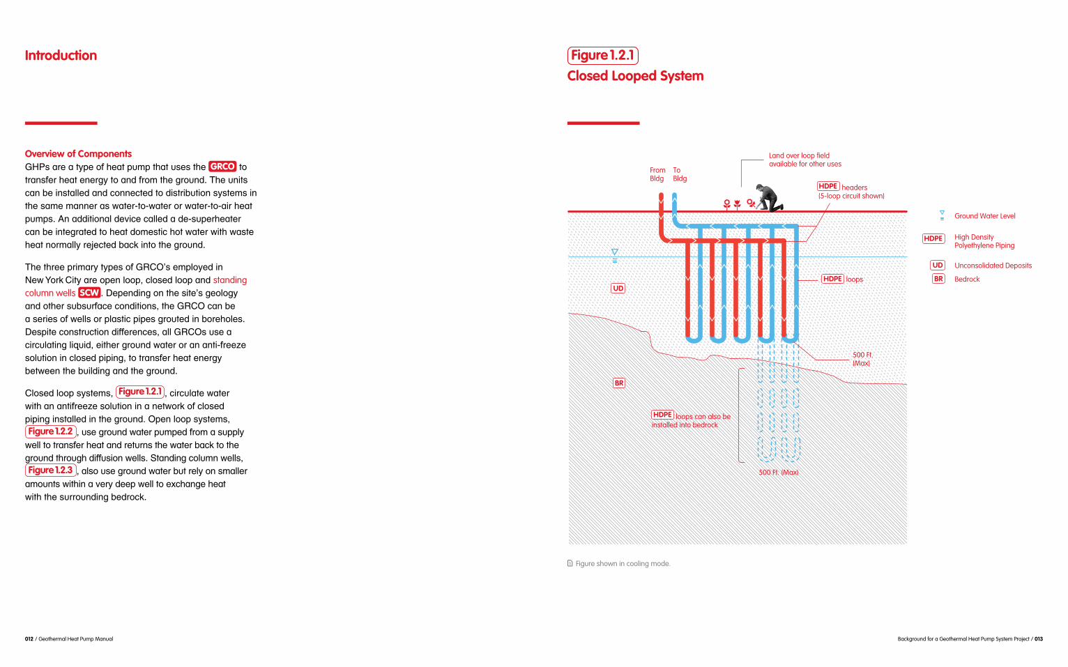
$$Preliminary Cost Estimate M$51Q&'$G&'+*&.$&E$ GHP $0,0+"5$-&0+0$*0$E'&5$2'*>>*.3F$#4*-4$*0$.&+$-&55&.$*.$G'&Q"-+0$#*+4$-&.:".+*&.1>$$HVAC $0,0+"50?$M22*+*&.1>$0*+"$*.:"0+*31+*&.$1>0&$*.-'"10"0$B&+4$+4"$2"0*3.$1.2$-&.0+'/-+*&.$-&0+0?$$M0$1$'"0/>+F$+4"'"$*0$1.$*.*+*1>$-&0+$G'"5*/5$+41+$51("0$HUD0$>"00$1++'1-+*:"?$U&#":"'F$&G"'1+*.3$1.2$>*E"P-,->"$-&0+0$1'"$/0/1>>,$5/-4$>&#"'$+41.$-&.:".+*&.1>$0,0+"50?$Table 1.2 $-&5G1'"0$+4"$1GG'&6*51+"$-&0+0$E&'$"1-4$GRCO $+,G"$B10"2$&.$1$7<<P+&.$-&&>*.3$0,0+"5?$
GHP Screening Table 1.1
GRCO Space Requirements
GRCO Ty
pe
Closed Loop 2 tons 50 loops 20 LF 21,800 sq ft. (0.5 acre)
1 ton @ 2 gpm† 1 supply well @ 200 gpm, 2 diffusion wells
150 LF to 250 LF, depending on hydrogeologic conditions
30,500 sq ft. (0.7 acre)
20 tons 5 wells 50 LF–75 LF 8,700 sq ft. (0.2 acre)
Open Loop
Standing Column Well
Heat T
ransfer
Capacit
y *
Number
of
Lo
ops o
r Well
s
Spacin
g
Re
quired
Area
Re
quired
* Based on subsurface conditions in NYC, may differ by location.
† A flow rate of 2 to 3 gpm is required for operation.
1. LF = linear feet of drilled borehole for loop or well
2. ton = measure of cooling capacity, approximately equal to 12,000 Btu/h
3. gpm = gallons per minute
4. Comparison is made based on a total cooling capacity of 100 tons
5. 1 acre is approximately 43,560 ft.
026 / Geothermal Heat Pump Manual
GRCO Ty
pe
Depth
Heat T
ransfer
Capacit
y
Number
of
Well
s or L
oops
Unit Cos
t per
Ins
tallatio
n*
Approxim
ate
Cos
t*
Closed Loop
Open Loop
Standing Column Well
Loops, 400–500 ft. each
6” Dia. Wells, 200–300 ft. each
Wells, 1,500 ft. depth each
2 tons
1 ton @ 2 gpm
15 tons
50 loops
1 supply well @ 200 gpm/2 diffusion wells
7 wells
$35,000 per loop
$125,000 per well
$200,000 per well
$1,750,000
$375,000
$1,400,000
Table 1.2
GRCO Estimated Costs
* Costs are approximate even at the time of publication. Actual costs may vary depending on specific project conditions and requirements.
Comparison is made based on a total cooling capacity of 100 tons.

028 / Geothermal Heat Pump Manual Geothermal Source Heat Pump System Components / 029
GRCO
Geothermal Heat PumpSystem Components
22.0List of Abbreviations
GHP
HTF HX
SCW
Geothermal Heat Pump
Heat Transfer Fluid
Standing Column Well
HDPE
HVAC
Ground Coupling High-Density Polyethylene
Heating, Ventilation, and Air Conditioning
Heat Exchanger

030 / Geothermal Heat Pump Manual Geothermal Source Heat Pump System Components / 031
2.1 GHP System Components
!"#$%&'%$()*)+,%-&./%$$+)+0&,+1& GHP &.-.#$*.&,%$&.#)((&)+&/2+.)1$%,#)2+3&'%24$/#&#$,*.&/,+&5$0)+&,&*2%$&1$#,)($1&%$6)$7&2"$&.-.#$*9&!+&$6,(:,#)2+&2"$H&*,)+&/2*;'2+$+#.3$&8$,#&':*'&:+)#&,+1$&GRCO 3&).&+$/$..,%-&,.&1).#)+/#&2'#)2+.&$<).#&"2%&$,/89&=%2'$%&:+1$%.#,+1)+0&2"&827&52#8&/2*'2+$+#.&,%$&/2**2+(-&)+.#,(($1&,+1&2'$%;,#$1&7)((&":%#8$%&/2+#%)5:#$&,&.://$..":(&>?=&'%24$/#9&
!(#82:08&>?=.&,%$&+2#&26$%(-&/2*'($<&.-.#$*.3$%$&&,%$&@$-&1)""$%$+/$.&"%2*&/2+6$+#)2+,(& HVAC &1$.)0+9&A2+/$'#.&:+1$%.#,+1&,%$B
All heat pumps use the refrigerant cycle to transfer heat energy. Unlike conventional air or water-cooled HVAC equipment, GHPs exchange heat with the ground as illustrated in Figure 2.1 GHP GRCO .
GHPs require nominal water flows of about 2 to 3 gpm per ton of rated capacity to maintain compressor efficiency. Properly sized GRCO pumps will meet the minimum rate at all times.
GHPs can supply sufficient heat to a building by virtue of heat transferred and recovered by the refrigerant cycle. Heat pumps can boost the circulating fluid temperature from a low of 20 °F to a high of 120 °F.
Each type of GRCO has an associated thermal capacity. The number of loops in a closed loop system or quantity of standing column wells must meet peak demand.
The thermal capacity of an open loop system is dependent on the pumping rate and ground water temperature. The aquifer beneath a site must therefore be able to supply and accept the required flow rate to meet peak demand.
The operating temperature of the heat transfer fluid is different for each type of system. Open loop systems use ground water that consistently ranges between 55°F to 65°F, while the fluid in closed loop and standing column well systems will have varying temperatures depending on the building operation and demand.
Refrigerant Loop
Building HVAC Loop Heating/Cooling Coils
Air Handler
Domestic HotWater Loop
Air Flow
Supplementary Heat Recovery
Point of heat exchange
Pump
GHP
GRCO
GHP SystemHeat Exchange Circuits
Figure 2.1

032 / Geothermal Heat Pump Manual Geothermal Source Heat Pump System Components / 033
2.2 Geothermal Heat Pumps
!& GHP &).&,+&,1,'#,#)2+&2"$&.#,+1,%1&8$,#&':*'3&78$%$$&0%2:+1&2%&0%2:+1&7,#$%&.$%6$.&,.$&8$,#&&.)+@&2%&8$,#&.2:%/$9&C)+/$&0%2:+1&#$*'$%,#:%$&).&/22($%,+&,)%&#$*'$%,#:%$.&)+$&.:**$%3&>?=.&/,+&5$&&
C)*)(,%(-3&>?=.&$<#%,/#&8$,#&"%2*$&0%2:+1&1:%)+0&$&7)+#$%3&,+1&/2*5)+$1&7)#8&8$,#&%$/26$%$1&"%2*&&
D8$&%$"%)0$%,+#&/-/($&,((27.&8$,#&':*'.&'%26)1$&&$)#8$%&/22()+0&2%&8$,#)+0&5-&#%,+."$%%)+0&8$,#&$+$%0-&5$#7$$+$&%$"%)0$%,+#&,+1&,+2#8$%&*$1):*9&E+&/22()+0&*21$3$&/2*'%$..2%&/2*'%$..$.&(27&'%$..:%$&%$"%)0;$%,+#&6,'2%&,+1&1)./8,%0$.&)#&,#&,&8)08$%&'%$..:%$&)+#2&$&/2+1$+.$%9&!&/22($%&*$1):*3&.:/8&,.&7,#$%3&#%,6$(.%2:08$&/2+1$+.$%3&,5.2%5.&8$,#&"%2*$&6,'2%&
&
%$1:/)+0&'%$..:%$&,((27$&%$"%)0$%,+#&52)(&)+$&$6,'2%,#2%9&!.$&%$"%)0$%,+#&$6,'2%,#$.3&)#&$<#%,/#.&$&8$,#&"%2*$&7,%*$%&,)%&',..)+0%2:08&)#9&&D8$&%$6$%.$&'%2/$..&2//:%.&)+&8$,#)+0&*21$9&
F$/,:.$&*2.#&>?=.&,%$&',/@,0$1& HVAC &:+)#.3$-&&
:'&GH;#2+.&/2**2+(-&:.$1&2+&/)#-&,+1&/2**$%/),(&'%24$/#.9&D8$&8$,#&':*'.&/,+&5$&1).#%)5:#$1%2:082:#$&5:)(1)+0&2%&/$+#%,()I$1&,#&2+$&(2/,#)2+9&D8$&*2.#&
7,#$%&,.&.827+&)+& Figure 2.2 9&
Water-to-Air These units are typically used to directly heat and cool the building spaces they serve. Figure 2.3.1
&and Figure 2.3.2 shows flow diagrams for a water-to-air
GHP in the cooling and heating modes.
Water-to-Water These units are typically used to indirectly heat and cool building spaces by producing chilled water for cooling or hot water for heating. The heating or cooling of building spaces is provided by auxiliary HVAC equipment serving individual locations such as radiators, fan coil units, or air handlers Figure 2.4.1
&and Figure 2.4.2 shows flow diagrams for a water-to-water GHP in the cooling and heating modes.
!&/2**2+&/2+/$%+&%$0,%1)+0&>?=.&).&78$#8$%$-&&/,+&'%26)1$&$+2:08&8$,#&*$$#&5:)(1)+0&8$,#)+0&(2,1.9&?27$6$%3$&%$"%)0$%,+#&/-/($&'%21:/$.&7,.#$&8$,#,#&/,+&5$&%$/26$%$1&,+1&:.$1&)+/%$,.$$&8$,#)+0&/,',/)#-&2"$.$&.-.#$*.9&D8$&8$,#&%$/26$%-&'%2/$..&$+,5($.&8$,#&':*'.&%,).$$&#$*'$%,#:%$&2"$&
&"2%&8$,#)+0&':%'2.$.9
Common GHP UnitsFigure 2.2
Water-to-Air
Air is supplied to the unit, conditioned, and ducted to spaces directly
Water-to-Water
Water is circulated through the unit, chilled or heated as needed, and piped to terminal units for space conditioning

034 / Geothermal Heat Pump Manual Geothermal Source Heat Pump System Components / 035
Water-to-Air Flow: Heating CycleFigure 2.3.2
Water-to-Air Flow: Cooling CycleFigure 2.3.1
Condenser
To/From
Evaporator
C
CA
EV
GRCO
HEA
HTFHTF
RR
RR
R
R
R
RRV
WA
Heat Exchanger Refrigerant-to-Air
Refrigerant
Compressor
Ground Coupling
Heat Transfer Fluid
Refrigerant Reversing Valve
Warm Air from Outsideor Return Air
Cool Air, supply to Conditioned Space
Expansion Valve
C
CA
EV
GRCO
HEA
HTF
R
RRV
WA
Supplementary Heat Recovery(Example: Desuperheater)
To/From
C
Condenser
Evaporator
Heat Exchanger Refrigerant-to-Air
Refrigerant
Compressor
Ground Coupling
Heat Transfer Fluid
Refrigerant Reversing Valve
Warm Air from Outsideor Return Air
Cool Air, supply to Conditioned Space
Expansion Valve
C
CA
CA
EV
EV
GRCO
GRCO
HEAHEA
HTF
R
R
RRV
RRV
WA
WA
HTFHTF
R
RR
R
R
R
Supplementary Heat Recovery(Example: Desuperheater)

036 / Geothermal Heat Pump Manual Geothermal Source Heat Pump System Components / 037
Water-to-Water Flow: Cooling Cycle
Figure 2.4.1
Warm Water from conditioned space
Heat ExchangerRefrigerant-to-Water
To/From
EV
Condenser
Supplementary Heat Recovery(Example: Desuperheater)
Evaporator
Refrigerant
Heat Transfer Fluid
Refrigerant Reversing Valve
C
CW
GRCO
HEW
HTFHTF
R
RR
R
R
R
R
RRV
WW
Compressor
Ground Coupling
Cool Air, supply to Conditioned Space
Expansion Valve
C
CA
EV
HEW
HTF
R
RRV
WW
GRCO
Water-to-Water Flow: Heating CycleFigure 2.4.2
GRCO
Evaporator
Condenser
To/From
EV
C
HEW
HTFHTF
R
RR
R
R
R
R
RRV
WW
CW
Supplementary Heat Recovery(Example: Desuperheater)
Warm Water from conditioned space
Heat ExchangerRefrigerant-to-Water
Refrigerant
Heat Transfer Fluid
Refrigerant Reversing Valve
Compressor
Ground Coupling
Cool Air, supply to Conditioned Space
Expansion Valve
C
CA
EV
HEW
HTF
R
RRV
WW
GRCO

038 / Geothermal Heat Pump Manual Geothermal Source Heat Pump System Components / 039
2.3 Ground Couplings
!& GHP &:.$.$&GRCO &#%,+."$%&8$,#&$+$%0-&&,+1&"%2*$&0%2:+19&!(#82:08&6,%)2:.&.-.#$*&2'#)2+.&&,%$&,6,)(,5($3$%$$&*,)+&#-'$.&2"&>JAK.&:.$1&)+&L$7&M2%@&A)#-&,%$&/(2.$1&(22'3&2'$+&(22'&,+1&.#,+1)+0&&/2(:*+&7$((.9&C-.#$*.&7)((&6,%-&5-&1$'#83&.',/)+03&,+1&heat transfer fluid& HTF 3&,.&.:**,%)I$1&)+& Table 2.1 9 Thermal Capacity !&@$-&/2+.)1$%,#)2+&"2%&>JAK.&).$%*,(&/,',/)#-3&&78)/8&).&:.$1&)+&.$($/#)+0&,+1&1$.)0+)+0&,+&,''%2'%),#$&
2%&7$((&1$'#83&/2+1:/#)6)#-&,+1$%*,(&1)"":.)6)#-&2"$&
#8$&0%2:+19& Table 2.2 &/2*',%$.$$%*,(&/,',/)#)$.&"2:+1&)+&#-')/,(&>JAK&)+.#,((,#)2+.9&A,',/)#)$.&'%26)1$1&,%$&0$+$%,()I$1&"2%$&/)#-&,+1&,%$&2+(-&%2:08&$.#)*,#$.&"2%&.-.#$*&.)I)+09&&>$+$%,((-3&/(2.$1&(22'&.-.#$*.&#$+1&8,6$$&($,.#&
(22'.9&E+&/2+#%,.#3&2'$+&(22'&.-.#$*.&8,6$&*:/8&8)08$%&/,',/)#-&5$/,:.$&2"&1)%$/#&0%2:+1&7,#$%&:.$9&C#,+1)+0&/2(:*+&7$((.&,(.2&2""$%&*2%$&/,',/)#-,+&/(2.$1&(22'&5:#%2:08&*:/8&1$$'$%&1%)(()+0&1$'#8.9&
Typical Configurations
Estimated Thermal Capacities
Table 2.1
Table 2.2
Syste
m Type
Syste
m Type
Closed Loop
Closed Loop
200–500 ft.
500 LF
20 ft. between loops
Water or water and non-toxic antifreeze mix
2.5–3.3 tons (30 to 40 MBH)
Open Loop
Open Loop
150–300 ft., depending on aquifer hydraulics
300 gpm,total flow rate
150–250 ft. between supply and diffusion wells
Ground water
100–200 tons (1,200–2,400 MBH)
Standing Column Well
Standing Column Well
1,500–1,800 ft.
1,500 LF
50–75 ft. between wells
Ground water
15–43 tons(180–500 MBH)
Typica
l Dep
th
Typica
l Insta
llatio
n
Spacin
g
Heat T
ransfer
Flu
id
Therm
al Capacit
y
Ra
nge f
or Typ
ical
Installa
tion
1. LF = Linear Feet
2. ton = measure of cooling capacity, approximately 12,00 Btu/h 3. MBH = measure of heating capacity, equal to 1,000 Btu/h 4. gpm = gallons per minute 5. For open loop systems, heat transfer is dependent on ground water flow rate and the temperature differential between supply and discharged water. Thermal capacity is therefore not directly related to well depth and cannot be generalized for rough system sizing.
1. ft.=Feet
150–200 LF
1.5–3.0 gpm
35–100 LF
Unit Th
ermal
Capacit
y

040 / Geothermal Heat Pump Manual Geothermal Source Heat Pump System Components / 041
Source Temperature&GHP &.-.#$*.&8,6$&
/2+.).#$+#&.2:%/$&#$*'$%,#:%$.&5$/,:.$&2"&.#,5($&0%2:+1&#$*'$%,#:%$.9&?27$6$%3&$,/8&GRCO &.-.#$*&8,.&,&1,)(-&,+1&.$,.2+,(&#$*'$%,#:%$&%,+0$3&78)/8&6,%)$. &&
5-&.-.#$*&,%$&.:**,%)I$1&)+& Table 2.3 9&
K'$+&(22'&.-.#$*.&8,6$&%$(,#)6$(-&/2+.#,+#&.2:%/$&#$*'$%,#:%$.&/2*',%$1&2#8$%&>JAK.&,.&0%2:+1&7,#$%&
7,#$%3&78)/8&*,-&5$&7,%*$%&2%&/22($%&1$'$+1)+0&2+&&>?=&2'$%,#)2+3&).&%$/8,%0$1&,+1&5($+1.&7)#8$&,*5)$+#&
5$#7$$+$&.:''(-&,+1&1)"":.)2+&7$((.3&0%2:+1&7,#$%&#$*'$%,#:%$.&%$*,)+&/2+.).#$+#(-&.#,5($9
D$*'$%,#:%$.&"2%&/(2.$1&(22'&,+1&.#,+1)+0&/2(:*+&&HTF &&
).&%$/)%/:(,#$19&!#$&5$0)++)+0&2"&.:**$%&2%&7)+#$%3&&
,#:%$9&?27$6$%3&)#.&#$*'$%,#:%$&7)((&0$+$%,((-&)+/%$,.$&26$%$&.:**$%&,+1&1$/%$,.$&26$%$&7)+#$%&,.&*2%$&8$,#&$+$%0-&).&%$4$/#$1&2%&$<#%,/#$1&"%2*$&0%2:+19&D8$&$<#$+1$1&#$*'$%,#:%$&%,+0$.&2"&>?=.&/,+&/2*'$+.,#$&"2%).&6,%),#)2+3&5:#&/2*'%$..2%.&7)((&&72%@&8,%1$%&1:%)+0&'$,@&1$*,+1&,+1&)+$&(,##$%&&',%#&2"&$,/8&.$,.2+9
Source TemperatureTemperature Ranges for Heat Transfer Fluid Table 2.3
Syste
m Type
Closed Loop Water or water and non-toxic antifreeze
70–90 °F 30–40 °F T between supply and return water is 5–10 °F. Peak summer temperatures can reach 90–100 °F. Peak winter temperatures can drop below 30 °F with use of antifreeze.
Open Loop Ground water 55–65 °F from supply well,65–85 °F to diffusion wells
55–65 °F from supply well, 35–45 °F to diffusion wells
Consistent supply well ground water temperature; return temperature to diffusion wells depends on T preference of designer.
Heat T
ransfer
Flu
idWint
er Opera
tion
Tem
peratur
e Rang
e
Summer
Operatio
n
Tem
peratur
e Rang
e
Remarks
1. Subsurface temperatures in NYC range from 55 to 65 °F.2. T = Delta T, or difference in temperature
Standing Column Well
Ground water 65–80 °F 35–50 °F T between supply and return water is 3–6 °F. Peak summer temperatures can reach 80–90 °F. During winter, care should be taken to prevent heat pump or wells from freezing. Well bleed cycle is recommended to control supply water temperature during peak cooling and heating load operation.

042 / Geothermal Heat Pump Manual Geothermal Source Heat Pump System Components / 043
Typical Closed Loop SystemFigure 2.5
HDPE
HDPE
HDPE
Bedrock
Ground Water Level
Geothermal Heat Pump
Land over loop field, potentially availablefor other uses
From
Headers (8 Borehole Circuit Shown)Circulator Pump
20 ft. Typical
High Density Polyethylene Piping
Unconsolidated Deposits
BR
BR
UD
UD
GHP
GHPGHPTo
loops
Closed Loop System&!&/(2.$1&(22'&.-.#$*&).&/2*'($#$(-&.$,($1&,+1&.$',%,#$1&"%2*$&.:%%2:+1)+0&$+6)%2+*$+#9&!(#82:08&82%)I2+#,(&
&
&2"&)+#$%/2++$/#$1&8)08;1$+.)#-&'2(-$#8-($+$& HDPE &'(,.#)/&')')+0&(22'.&)+.#,(($1&)+&1%)(($1&6$%#)/,(&52%$82($.&*,@$.&5$##$%&:.$&2"&()*)#$1&.',/$&,.&)((:.#%,#$1&)+& Figure 2.5 9
&2%&7,#$%&*)<$1&7)#8&,&+2+;#2<)/3&5)21$0%,1,5($&,+#);&"%$$I$&.:/8&,.&"221;0%,1$&'%2'-($+$&0(-/2(9&=:*'.&(2/,#$1&)+.)1$$&5:)(1)+0N.&*$/8,+)/,(&%22*&/)%/:(,#$&&
OPG 0'*&'$%+&2"&)+.#,(($1&8$,#&':*'&/,',/)#-9&?$,#&$</8,+0$&2//:%.%2:08&/2+1:/#)2+&5$#7$$+$& HTF &/)%/:(,#)+0&)+$&
&).&$..$+#),(&"2%&'%2'$%&.)I)+0&,+1&1$.)0+&2"&,&/(2.$1&&(22'&.-.#$*3&,+1&)+62(6$.&1%)(()+0&,&52%$82($3&)+.#,(()+0&&,&(22'3&,+1&/2+1:/#)+0&,$%*,(&/2+1:/#)6)#-&#$.#9
Figure shown in cooling mode.
Closed Loop System

044 / Geothermal Heat Pump Manual Geothermal Source Heat Pump System Components / 045
Figure 2.6 &)((:.#%,#$.&,+&)+1)6)1:,(&(22'&,+1&52%$82($&
,..$*5(-&).&(27$%$1$&52##2*3&,+1&'%$..:%$&#$.#$1&,.&.827+&)+& Figure 2.7 9&E"&+2&($,@.&,%$&1$#$/#$13$+&,$%*,((-;$+8,+/$1&0%2:#&).&':*'$1&)+#2$&52%$82($99&
#8$&,++:(,%&.',/$&5$#7$$+$&(22'&')')+0&,+1&52%$82($&7,((9& Figure 2.8 &.827.&0%2:#)+0&)+&'%20%$..&7)#8$&0%2:#&5$)+0&1$()6$%$1%2:08&,&.$',%,#$&')'$$&
2"$&52%$82($3&':*')+0&).&#$%*)+,#$19&K+/$$&0%2:#&
2"&0%2:+1&7,#$%3&,+1&$+,5($.&0221&/2+1:/#)2+&7)#8$&.:%%2:+1)+0&$+6)%2+*$+#9&
,''%2<)*,#$(-&OH&"$$#&,',%#3&,((27)+0&"2%&.2*$&26$%(,'9&?2%)I2+#,(& HDPE &')')+0&/2++$/#.$&(22'.$#8$%&&/%$,#$&/)%/:)#.3&#-')/,((-&"2:%&#$+&(22'.&'$%&/)%/:)#9&&D8$&/)%/:)#&')')+0&).&%2:#$1&,&*,+)"2(1&$)#8$%&)+.)1$&$&5:)(1)+0&2%&,+&2:#.)1$&6,:(#9&Q,%0$%&1),*$#$%&*,)+&8$,1$%.&/2++$/#$&*,+)"2(1&>?=.9&!((&$<#$%)2%&82%)I2+#,(&')')+0&).&)+.#,(($1&)+&#%$+/8$.&5$(27$&"%2.#&
Figure 2.6Closed Loop Construction
If loop depth is within UD, then mud rotary drill method is used. If loop depth extends into BR, then air rotary methodis used.
Detectable tape at 18” below ground surface
Connection to header
Backfill to ground surface
Maximum 6” diameter borehole
U-bend
loop
thermally enhanced grout
Horizontal piping
If depth to is <50’, driller typically removes casing after grouting to re-use on next hole.
If is deeper, it may be physically impossible to remove or more cost effective to leave in place
Detectable tape provides a warning for future excavations in areas with underground HDPE piping.
HDPEHDPE
HDPE
Bedrock
Ground Water Level
High Density Polyethylene Piping
Unconsolidated Deposits
BR
BR
BR
BR
UD
UD
Closed Loop System
D8$%*,(&/,',/)#-&2"&,&6$%#)/,(&/(2.$1&(22'&.-.#$*&).&1$'$+1$+#&2+&1$'#83$%*,(&/2+1:/#)6)#-&,+1&1)"":.)6)#-&&2"$&.:5.:%",/$&*,#$%),(.3&0%2:#&.:%%2:+1)+0$&(22'&
HTF &&
()+$,%&"$$#&2"&(22'&).&#-')/,((-&+$$1$1&"2%&2+$+&2"&&&
RF?3&2"&/,',/)#-9

046 / Geothermal Heat Pump Manual Geothermal Source Heat Pump System Components / 047
Pressure Testing of Loop Loop InstallationFigure 2.7 Figure 2.8

048 / Geothermal Heat Pump Manual Geothermal Source Heat Pump System Components / 049
!+&2'$+&(22'&.-.#$*&:.$.&0%2:+1&7,#$%&"2%&8$,#&$</8,+0$&5-&$<#%,/#)+0&,+1&%$#:%+)+0&7,#$%%2:08&
Figure 2.9 &)((:.#%,#$.$&5,.)/&.-.#$*&(,-2:#&78$%$&,&127+;82($&.:5*$%.)5($&':*'&1$()6$%.&0%2:+1&7,#$%&,#&,*5)$+#&#$*'$%,#:%$9&!(#82:08&.2*$& GHP &8,6$&,+&)+#$0%,#$1&8$,#&$</8,+0$%3&,&.$',%,#$&'(,#$;"%,*$&8$,#&$</8,+0$%& HX &).&,+&2'#)2+,(&1$6)/$,#&*,-&5$&
,&'8-.)/,(&.$',%,#)2+&5$#7$$+&0%2:+1&7,#$%&,+1$&&>?=&:+)#3&78)/8&()*)#.$&$<'2.:%$&2"&/2+#,*)+,+#.&&
>%2:+1&7,#$%&',..$.%2:08$&.-.#$*&2+/$&5$"2%$&
1)"":.)2+&7$((.&,%$&0$+$%,((-&%$/2**$+1$1&"2%&$,/8&&
1)""$%$+/$&5$#7$$+$&.:''(-&,+1&%$#:%+$1&7,#$%&).&#$*'$%,#:%$&,.&8$,#&).&$</8,+0$19
/,.)+0&,+1&,&.#,)+($..&.#$$(&7$((&./%$$+&,#$&(27$%&'2%#)2+&2"$&52%$82($9& Figure 2.10 &.827.&,&7$((&./%$$+&.$0*$+#&1:%)+0&)+.#,((,#)2+9&K'$+)+0.&)+$&./%$$+&
if used
Cone of Depression
To From
Return Flow To Diffusion Wells
Ground Water Mounding
Maintain overhead clearance above well head for servicing
Manhole covers
Supply WellDiffusion Wells
Well Screen
Submersible Pump
Open Loop Geothermal System
Ground Water
GW
Bedrock
Ground Water Level
Geothermal Heat Pump
Unconsolidated Deposits
BR
BR
UD
UD
GHP
GHPGHP
Heat ExchangerHX
HX
GW
Open Loop Well SystemFigure 2.9
#2&.:''(-&,+1&,//$'#&,&/2+.).#$+#&S92"&/,',/)#-9&?-1%20$2(20)/,(&.#:1)$.&2"&,&',%#)/:(,%&,%$,&"%2*&,&%$(),5($&.2:%/$&.:/8&,.$& USGS &,%$&$..$+#),(&
2%&*2%$&#$.#&7$((.9&K'$+&(22'&.-.#$*.&,%$&2+$&2"$&*2%$&/2**2+&.-.#$*.&:.$1&)+&F%22@(-+&,+1&T:$$+.&
&
!&@$-&/2+.)1$%,#)2+&)+&2'$+&(22'&.-.#$*&1$.)0+&).&7$((&
#8$&7,#$%&($6$(&.:%%2:+1)+0&,&.:''(-&7$((&).&1%,7+&127+3&
#8$%$&).&:.:,((-&,&*2:+1)+0&$""$/#&,%2:+1&$,/8&2"$&1)"":.)2+&7$((.9&!(#82:08&,&*)+)*:*&2"&S O H&()+$,%&"$$#&5$#7$$+&.:''(-&,+1&1)"":.)2+&7$((.&).&%$/2**$+1$1&
%N.&8-1%,:()/&&
,+1&,++:,(&':*'&%:+&#)*$.9
Open Loop System

050 / Geothermal Heat Pump Manual Geothermal Source Heat Pump System Components / 051
Well Screen Installation and DetailFigure 2.10
&*,-&/,:.$$%*,(&5%$,@#8%2:083&78$%$&7,#$%&%$#:%+)+0&
$&.:''(-&.)1$9&!11)#)2+,((-3&.:''(-&7$((.&.82:(1&5$&(2/,#$1&:'0%,1)$+#&2"&1)"":.)2+&7$((.3&,((27)+0&+,#:%,(&0%2:+1&7,#$%&*26$*$+#&1)%$/#&1)./8,%0$1&7,#$%&,7,-&"%2*$&.:''(-&,%$,&,+1&":%#8$%&%$1:/$&'2#$+#),($%*,(&$""$/#.9&!+#)/)',#$1&':*')+0&%,#$.&/,+&,(.2&,""$/#&7$((&.',/)+0&,.&,&(27$%&%,#$&7)((&%$.:(#&)+&,&8)08$%&#$*'$%,#:%$&1)""$%$+#),(&5$#7$$+$&.:''(-&,+1&%$#:%+&.)1$9&!&8)08$%&
5$#7$$+&.:''(-&,+1&1)"":.)2+&7$((.&%$1:/$$&%).@&&2"$%*,(&5%$,@#8%2:089
#2&()*)#$&/2*5)+$1&1%,7127+&$""$/#.&2+&$,/8&2#8$%&@+27+&,.&7$((&)+#$%"$%$+/$9&C)*)(,%(-3&*:(#)'($&1)"":.)2+&7$((.&.82:(1&5$&'%2'$%(-&.',/$1&,62)1&0%2:+1&7,#$%&*2:+1)+0&)+$&,%$,3&',%#)/:(,%(-&,#&'%24$/#&.)#$.&78$%$&
/%$,#$&8)08$%&5,/@'%$..:%$.&2+&.-.#$*&':*'.3&78)/8&&/,+&(27$%&':*')+0&%,#$.3&)+/%$,.$$&#$*'$%,#:%$&
!#&%$(,#)6$(-&.*,((&.)#$.&7)#8&*21$%,#$&8)08&5:)(1)+0&
,//$'#,5($&7)#82:#&.$%)2:.(-&/2*'%2*).)+0&.-.#$*&&
)+0&2%&/2*':#$%&*21$()+09&C:''(-&,+1&1)"":.)2+&7$((&./%$$+.&/,+&,(.2&5$&.$',%,#$1&6$%#)/,((-&8$('&,62)1&26$%(,'3&5:#&52#8&*:.#&5$&)+.#,(($1&7)#8)+$&.,*$&
(22'&1$.)0+9&>%2:+1&7,#$%&,+,(-.).&).&%$/2**$+1$1&1:%)+0$&./8$*,#)/&1$.)0+&'8,.$&1$#$%*)+$&&/8$*)/,(&/2*'2:+1&($6$(.,#&/,+&,""$/#&.-.#$*&2'$%,#)2+&,+1&$6,(:,#$&*$,.:%$.&,11%$..&'22%&
*$#,(.&.:/8&,.&)%2+3&2%0,+)/&'2((:#,+#.3&8)08&.,()+)#-3&&,+1&5,/#$%),9&D8$.$&/2*'2:+1.&/,+&($,1&./,()+03&5)2"2:()+0&2%&/2%%2.)2+&2"&*$#,(()/&')')+03&6,(6$.&,+1&
&2"&)%2+;%$(,#$1&5,/#$%),&,+1$)%&5-'%21:/#.&)+$&'%$.$+/$&2"&8)08&)%2+&,+1&2%0,+)/&*,##$%&)+&,&7$((9&
&?)08&*,)+#$+,+/$&/2.#.&,+1&$6$+&/2*'($#$&.-.#$*&
&)+&1$.)0+9&
Open Loop System

052 / Geothermal Heat Pump Manual Geothermal Source Heat Pump System Components / 053
&2"&',%#)/:(,#$.&.:/8&,.&.,+13&.)(#3&,+1&/(,-,#&/,+&$+#$%&
,+1&.:5*$%.)5($&':*'&1,*,0$9&C(2#&.)I$.&.82:(1&,(.2&5$&
#8%2:082:#$&1$'#8&2"$&7$((9
5$#7$$+$&./%$$+&,+1$&52%$82($3&78)/8&.#,5)()I$.$&52%$82($&,0,)+.#$&./%$$+9&E#&,(.2&.$%6$.&)*'%26$$%*,(&/2+1:/#)6)#-&5-&)+/%$,.)+0$&7$((N.&$""$/#)6$&
$&,''%2'%),#$&'2%2.)#-&,((27&'%2'$%&0%2:+1&7,#$%&&
.,+1&).&#-')/,((-&:.$19& Figure 2.11 &)((:.#%,#$.$&#-')/,(&7$((&/2+.#%:/#)2+&"2%&,+&2'$+&(22'&.-.#$*9
Open Loop Well ConstructionFigure 2.11
,+-&%$.)1:,(&,18$%$+/$$&7$((&./%$$+&,+1$&.:%;
&).&*)+)*,(9&U%)(($%.&.82:(1&,(.2&1).)+"$/#&,((&127+;82($&
D8$$%*,(&/,',/)#-&2"&,+&2'$+&(22'&.-.#$*&).&1$'$+1$+#&2+$&#$*'$%,#:%$&1)""$%$+/$&5$#7$$+&$&0%2:+1&7,#$%&2+$&.2:%/$&.)1$&,+1$&5:)(1)+0&/)%/:(,#)2+&(22'&2+$&(2,1&.)1$9&D8).&1)""$%$+/$&).&&@+27+&,.$&,''%2,/8&#$*'$%,#:%$3&2%& D9&D8$& GHP &.-.#$*&1$.)0+$%&1$#$%*)+$.& D3&78)/8&#-')/,((-&6,%)$.&
&&
/,',/)#-&2"&,+&2'$+&(22'&.-.#$*&,#&,&':*')+0&%,#$&&&&
7)#8&,&
Submersible Pump(supply well only)
Grout
Supply or Return
Borehole
Well casing
Well screen
Sediment trap (depth varies)
Filter pack
The pump intake must be set below the deepest drawdown in the well to avoid motor burnout.
Manhole cover
Bedrock
Ground Water Level
Unconsolidated Deposits
BR
BR
UD
UD
Open Loop System

054 / Geothermal Heat Pump Manual Geothermal Source Heat Pump System Components / 055
!&.#,+1)+0&/2(:*+&7$((& SCW &).&,&6,%),#)2+&2+&,+&&2'$+&(22'&.-.#$*,#&/2*5)+$.$&.:''(-&,+1&1)"":.)2+&'%2/$..&)+$&.,*$&7$((9&!.&7)#8&,+&2'$+&(22'&.-.#$*3&0%2:+1&7,#$%&).$& HTF1$$'$%,+&,+&2'$+&(22'&7$((&,+1&).&)+.#,(($1&)+&5$1%2/@&
1%)(($1&,.&1$$'&,.&S3VHH&"$$#&)+$&/)#-9& Figure 2.12 &)((:.#%,#$.&,&/2+6$+#)2+,(&.#,+1)+0&/2(:*+&7$((&.-.#$*9
New York State Department of Environmental Conservation NYSDEC &%$0:(,#)2+.9&F$(27).&1$'#83$&7$((&).&,&.$(";.:''2%#)+03&:+/,.$1&2'$+&52%$82($9& Figure 2.13 &)((:.#%,#$.$&#-')/,(&.#,+1)+0&/2(:*+&7$((&/2+.#%:/#)2+&,+1&)+1)/,#$.$&'(,/$*$+#&2"$&.:%",/$&/,.)+0&&7)#8)+$&52%$82($9&
&
/,(($1&,&=2%#$%&C8%2:13&).&)+.$%#$1&)+#2$&52%$82($3&&78)/8&).&.*,(($%,+$&7$((&1),*$#$%3&,+1&$<#$+1.&$&$+#)%$&($+0#8&2"$&7$((9&=$%"2%,#)2+.&,#$&52##2*&,((27&0%2:+1&7,#$%&$+#$%3&78)($&,&.:5*$%.)5($&&
Standing Column Well SystemFigure 2.12
':*'&.$#&5$(27$&7,#$%&#,5($&7)#8)+$&7$((&':*'.&0%2:+1&7,#$%$&5:)(1)+09& Figure 2.14 &.827.$&,''%2<)*,#$&.)I$&2"&,&#-')/,(&.:5*$%.)5($&':*'9&D8$&%$#:%+&')'$&).&,(.2&(2/,#$1&,#$'&2"$&7$((3&5:#&
,++:(:.3&)#&$</8,+0$.&8$,#&7)#8$&.:%%2:+1)+0&5$1%2/@9&D8$&'%2/$..&).&%$'$,#$1&78$+$&0%2:+1&7,#$%&).&1%,7+&
.-.#$*&12$.&+2#&%$(-&2+&(,%0$&,*2:+#.&2"&0%2:+1&7,#$%3&
52#8$&.:5*$%.)5($&':*'&,+1$& GHP 9&
D-')/,(&.',/)+0&5$#7$$+&*:(#)'($&7$((.&.82:(1&5$&&GRCO 3&.2*$&
!0,)+3&/(2.$%&.',/)+0&*,-&,""$/#$&'$%"2%*,+/$&&2"$&.-.#$*9&A2*':#$%&*21$()+0&,+1&,''%2'%),#$&/,(/:(,#)2+.&.82:(1&5$&:.$1&6$%)"-&)").&#-'$&2"&&.-.#$*&).&.#)((&6),5($&"2%$&'%24$/#9
Plate-frame heat exchanger, if used
1500 ft.(TYP)
1500 ft.(TYP)
1500 ft.(TYP)
Maintain overhead clearance above well head for servicing
Manhole covers
Bedrock
Ground Water Level
Unconsolidated Deposits
BR
BR
UD
UD Submersiblepump
Perforatedintake
Standing Column Well System

056 / Geothermal Heat Pump Manual Geothermal Source Heat Pump System Components / 057
Standing Column Well Construction
Steel surface casing
Perforated intake
Conductor casing,removed and re-usedor left in place
Min. 75 ft. into bedrock
Return pipe
Supply
Return
Porter Shroud
Borehole Wall
Submersible pump
Ground Water
Bedrock
Ground Water Level
Unconsolidated Deposits
BR
BR
UD
UD
GW
GWGW
Manhole cover
Figure 2.13 Submersible PumpFigure 2.14

058 / Geothermal Heat Pump Manual Geothermal Source Heat Pump System Components / 059 Geothermal Source Heat Pump System Components / 059
Illustration of Standing Column Well BleedFigure 2.15
Ground Water
Bedrock
Ground Water Level
Cone of Depression
Unconsolidated Deposits
BR
CD
UD
GW
BR
UD
Effect of bleed on ground water level
+/- 10% Flow diverted away from well during bleed cycle
Ground water flowfrom bedrock fractures
Water level in borehole is lowered during bleed
Submersible pump
Reduced return flow
To From
DrawdownCD
GW
GW
GHP GHP
Manhole cover
F($$1&).&,&/2**2+&'%,/#)/$&:.$1&2'#)*)I$& SCW'$%"2%*,+/$&,+1$&,5)()#-&5($$1&*,-&%$1:/$$&#,(&7$((&1$'#89&F-&1)6$%#)+0&,&.*,((&'$%/$+#,0$&2"&%$#:%+&7,#$%&"%2*$&7$((3&5($$1&1%,7.&)+&"%$.8&0%2:+1&7,#$%&"%2*&1$$'$%&5$1%2/@&"%,/#:%$.&*21$%,#$&7$((&7,#$%&#$*'$%,#:%$3&,.&)((:.#%,#$1&)+& Figure 2.15 9&U:%)+0&'$,@&/22()+03&8)08&7$((&7,#$%&#$*'$%,#:%$.&1$/%$,.$&8$,#&
#$*'$%,#:%$.&,''%2,/8&"%$$I)+0&/2+1)#)2+.3&,+1&5($$1)+0&
#$*'$%,#:%$&1%2'9
K+/$&.:''(-&7,#$%&#$*'$%,#:%$.&%$#:%+$&1$.)0+&%,+0$3&5($$1&).&%$1:/$1&2%&#$%*)+,#$19&F($$1&1:%,#)2+.&#-')/,((-&.82:(1&+2#&(,.#&"2%&*2%$,+&,&"$7&82:%.&1:%)+0&'$,@&$+$%0-&1$*,+19&D8$&1$.)0+$%&.82:(1&5$&,7,%$,#$&/2*5)+$1&1%,7127+&$""$/#&2"&*:(#)'($&7$((.&5$)+0&
1%,7127+&$""$/#&*,-&'2#$+#),((-&$<#$+1&5$-2+1$&'%2'$%#-&()+$&)+#2&,14,/$+#&'%2'$%#)$.9&=%2(2+0$1&2%&%2:#)+$&5($$1)+0&1:%)+0&+2%*,(&(2,1&/2+1)#)2+.&.82:(1&5$&,62)1$1&2%&0%2:+1&7,#$%&($6$(.&*,-&5$&'$%*,+$+#(-&(27$%$19&&
&':*')+0&,+1&,16$%.$&$""$/#.&2+&2#8$%&7$((.9
F,.$1&2+&/2*':#$%&*21$()+0&,+1&$*')%)/,(&1,#,3$&
,''%2<)*,#$(-&SHH&0'*3$&2'#)*:*&5($$1&%,#$&72:(1&&5$&%2:08(-&SH&0'*9&F($$1&).&'2..)5($&2+(-&"2%&7$((.,#&
/2+#)+:2:.&,+1&0%$,#$%,+$&1$.)0+&5($$1&%,#$&.2&,#&1%,7127+&).&*)+)*)I$19
Standing Column Well System
1$'#83&/2+1:/#)6)#-&,+1&1)"":.)6)#-&2"$&5$1%2/@&"2%*,;&
,+1&#$*'$%,#:%$&1)""$%$+/$&5$#7$$+&/)%/:(,#)+0&0%2:+1&&&
2//:%.&)+&7$((.,#&-)$(1&()*)#$1&0%2:+1&7,#$%3&,+1:.&&
&OH+.&2"&/,',/)#-&)+$&/)#-9
52%$82($.,#&)+#$%.$/#&7,#$%;5$,%)+0&"%,/#:%$.3&",:(#.&&2%&42)+#.&)+&5$1%2/@9&D8$.$&/2+1)#)2+.&,((27&0%2:+1&7,#$%&
/2(:*+&7)#8&(27$%&#$*'$%,#:%$&0%2:+1&7,#$%9&

060 / Geothermal Heat Pump Manual Schematic Design / 061
Schematic Design
33.0List of Abbreviations
GHPDTB
SCW
DTWGeothermal Heat Pump
Depth to Bedrock
Standing Column Well
Depth to Ground Water
GRCO HDPE HVACGround Coupling High-Density
PolyethyleneHeating, Ventilation, and Air Conditioning

062 / Geothermal Heat Pump Manual Schematic Design / 063
3.1 Schematic Design
!"#$%&'()*'+,)*-.($,'/*+$&%'0).+*1'.'/*+$&%'(*.-'*2.3".(*+'/$44*#*%('50($5%+'(5'.//#*++'.'0#56*,(7+'%**/+1'&5.3+'.%/',5%+(#.$%(+8'9)*%'.' GHP '+:+(*-'$+';*$%&',5%+$/*#*/1'.%'.//$($5%.3'3.:*#'54'.%.3:+$+'$+'%*,*++.#:''(5'*%+"#*'.00#50#$.(*'+:+(*-'+*3*,($5%'.%/'0#50*#'*<*,"($5%8'=*,."+*'0#*3$-$%.#:'+,#**%$%&'$+'.';#5./'.++*++-*%('54'0#56*,(',5%/$($5%+1'+$(*'$%2*+($&.($5%+''.%/',.#*4"3'+:+(*-'*2.3".($5%'+)5"3/';*',5-03*(*/';*45#*'4"#()*#'/*+$&%8
>35%&'?$()'+$(*'0#50*#($*+'+",)'.+'&*535&$,'.%/'
.+',5%+(#",($5%'+,)*/"3*'.%/'#*@"$#*/'-.$%(*%.%,*'-.:'/$,(.(*'+:+(*-'/*+$&%8'A)*'/*+$&%'(*.-'-"+(',5--"%$,.(*'?$()'()*';"$3/$%&'5?%*#'.%/'50*#.(5#''
#*+532*/'*.#3:'5%'-.:'3*./'(5'3.#&*#'.%/'-5#*'*<0*%B'+$2*'0#5;3*-+'$%'()*'4"("#*8'>('-$%$-"-1'()*'*%($#*''0#56*,('(*.-'?$33'%**/'(5'*2.3".(*'()*'45335?$%&'0#$5#''(5'+*3*,($%&'.%/'/*+$&%$%&'.'CDE'+:+(*-F
Installation costs
Filings and permit requirements
Project schedule
System reliability
Operation and maintenance
Architectural impact
Construction impact on neighbors
3.2 Geology and Hydrogeology
G*?'H5#I'J$(:7+'&*535&:'$+'@"$(*',5-03*<'.%/'2.#$*+'
,).33*%&*'45#'$-03*-*%($%&' GHP '+:+(*-+8'K%/*#+(.%/$%&')5?'()*+*'+:+(*-+'$%(*#.,('?$()'()*'"%/'$+'*++*%($.3'45#'0#50*#'/*+$&%'.%/'#*@"$#*+'.';#$*4'52*#2$*?'54'&*535&:'
'()*'J$(:'#.%&*'4#5-'E#*,.-;#$.%';*/#5,I'L8M';$33$5%'':*.#+'53/'(5'-5/*#%'"%,5%+53$/.(*/'/*05+$(+'3*++'().%''
?.(*#'.@"$4*#+'.%/'()*$#',)*-$,.3',).#.,(*#$+($,+''
0#50*#($*+8'A)*#*45#*1'.'+$(*7+'/$+($%,('):/#5&*535&$,''
.#*'+"$(.;3*'.%/'&"$/*'()*'"3($-.(*'GRCO '+*3*,($5%8
General''
;:'.'3.:*#'54'"%,5%+53$/.(*/'&3.,$.3'/*05+$(+'52*#3:$%&'2.#$5"+'(:0*+'54',#:+(.33$%*';*/#5,I8'N.#$.($5%+'*<$+(''$%'()*$#'5#$&$%1'/$+(#$;"($5%1'()$,I%*++1'.%/'):/#."3$,'0#50*#($*+8'K%,5%+53$/.(*/'/*05+$(+'.#*',5-05+*/'54'+.%/1'+$3(1',3.:1'&#.2*31'5#'-$<("#*+'()*#*548'A)*:'&*%*#B.33:',5%(.$%'"%/'?.(*#'.%/',.%'#*./$3:':$*3/'3.#&*1'+"+(.$%.;3*'.-5"%(+'4#5-'0#50*#3:',5%+(#",(*/'?*33+8
'-.(*#$.3'().('(:0$,.33:'0#52$/*+'35?':$*3/+'"%3*++')$&)3:'
;*/#5,I'$+'45"%/'.('()*'+"#4.,*'$%,3"/*'J*%(#.3'E.#I'$%'
:5"%&*#'"%,5%+53$/.(*/'/*05+$(+1'?)*#*'0#*+*%(8
Figure 3.1 '$+'.%'$33"+(#.(*/'):/#5&*535&$,',#5++B+*,($5%''()#5"&)'=#55I3:%'.%/'O"**%+'.%/'/*3$%*.(*+'()*'"%,5%+53$/.(*/'/*05+$(+'().('45#-'()*'):/#5&*535&$,'+:+(*-8'=*/#5,I'$+',35+*+('(5'()*'+"#4.,*'.35%&'()*''P.+('Q$2*#'.('.'0*.I'*3*2.($5%'54'RLS'4**('.;52*'-*.%'+*.'3*2*3'.%/'/#50+'544'+(**03:'(5'BL1LTT'4**('.('()*'Q5,I.?.:+';:'()*'>(3.%($,'U,*.%1'.%'.00#5<$-.(*''+350*'54'VT'4**('0*#'-$3*8'>+'()*';*/#5,I'/*0()'/**0*%+1'()*'52*#3:$%&'/*05+$(+'()$,I*%'.%/'45#-'/$+($%,('):/#5&*535&$,'"%$(+8
(5'()*'+"#4.,*'?$()'()$%'3.:*#+'54'52*#3:$%&'/*05+$(+'$%'
).2*'.'+$-$3.#'/$+(#$;"($5%'.+'W.%).((.%'.%/'=#5%<'?)$3*'()*'*.+(*#%'.%/'+5"()*#%'05#($5%+'54'()*'$+3.%/'.#*'-5+(3:'"%,5%+53$/.(*/1'+$-$3.#'(5'=#55I3:%'.%/'O"**%+8

064 / Geothermal Heat Pump Manual Schematic Design / 065
Unconsolidated Deposits'A)*' USGS '9.(*#'Q*+5"#,*+'!$2$+$5%'0#52$/*+'
'()*'J$(:1'*+0*,$.33:'=#55I3:%'.%/'O"**%+8' Table 3.1 '
'5%'()*'0#$%,$0.3'):/#5&*535&$,'"%$(+1'0#$-.#:'35,.($5%+'.%/'()*$#'?.(*#';*.#$%&'0#50*#($*+8'>3()5"&)'()*#*'.#*'
''
GHP '+:+(*-+8
E3*$+(5,*%*'-.(*#$.3+'?*#*'/*05+$(*/'/"#$%&'()*''3.+('&3.,$.3'0*#$5/'.%/'&*%*#.33:',5%(.$%'3.#&*'253"-*+''54'"%/'?.(*#8'>+'&3.,$*#+'./2.%,*/'4#5-'()*'%5#()1'+,5"#$%&'.%/'*#5/$%&'()*'(50'54';*/#5,I1'()*:'*%(#.$%*/'
'()*'$,*'-.++8'>+'()*'&3.,$*#+'#*,*/*/1'()*'-*3(?.(*#'/*05+$(*/'()$+'-.(*#$.3'.('()*'+"#4.,*1'?)$,)'0#*+*%(3:'
/*05+$(+'45#-'()*'"00*#'&3.,$.3'.@"$4*#'.%/',5%+$+(''54'&3.,$.3'5"(?.+)'.%/'(?5'(:0*+'54'&3.,$.3'($331'(*#-$%.3'.%/'"%/'-5#.$%*8' Figure 3.2 '5"(3$%*+'()*'&*%*#.3'*<(*%('.%/'35,.($5%'54'()*+*'/*05+$(+'$%'()*',$(:8'
Hydrogeologic Cross-Section of Brooklyn and QueensFigure 3.1
Mean SeaLevel
-200
-400
-600
-800
-1000
MeanSea Level
-200
-400
-600
-800
-1000
+200 FtA
+200 Ft
A1
East
Riv
er
Jam
aica
Bay
Atla
ntic
Oce
an
Cret
aceo
us*
* Pleistocene and Cretaceous refer to the geologic age of the overlying deposits.
Plei
stoc
ene*
Upper Glacial aquifer Raritan clay
Gardiners clay
Jameco aquifer
Magothy aquifer
Lloyd aquifer
BedrockA1
AUG
UG
GC
GC
J
J
M
M
RC
RC
L
L
BR
BR
* Section A above refers to Cross section below
Geology and Hydrogeology

Schematic Design / 067 066 / Geothermal Heat Pump Manual
Summary of Unconsolidated Deposits
Geolog
ic
Tim
eGeo
logic
Unit Hyd
rogeo
logic
Unit Ra
nge o
f
Th
ickne
ss (ft.
)
Loca
tion b
y
Boro
ugh
Characte
ristic
s
Water Bea
ring
Pro
perties
Table 3.1Distribution of Surficial Deposits in New York CityFigure 3.2
Approximate Distribution Of All Surficial Glacial Deposits In New York City
Figure 3.3
Long Isl
and Sound
Huds
on R
iver
Atlantic Ocean
Legend
Till (Ground Moraine)
Till (Terminal Moraine)
Outwash Deposits (Sand and Gravel)
Southernmost Extent ofTerminal Moraine (Harbor Hill)
Direction of Glacial Movement
Brooklyn/Queens Border
Queens
Brooklyn
Staten Island
Bronx
Manhattan
Pleistocene
Cretaceous
10,000 years to 1.8 million years B.P.
65 million years to 145 million years B.P.
Till (ground and terminal moraine)
Magothy Formation
Raritan Clay Unit
Lloyd Sand Member
Till (mostly along north shore and in moraines) composed of clay, sand, gravel, and boulders Outwash deposits (mostly between and south of terminal moraines, but also inter-layed with till) consist of quartzose sand, fine to very coarse, and gravel, pebble to boulder sized
Difficult drilling conditions Till has low permeability Outwash deposits are moderately to high permeability
Most layers are poorly to moderately permeable, some locally are highlypermeable. Water is unconfined in uppermost parts, elsewhere is confined. Water is generally of excellent quality, but locally has high iron content along north and south shores
Poor to very poorpermeability constitutes confining layer for underly-ing Lloyd aquifer. Very few wells produce appreciable water from these deposits
Poor to very poorpermeability. Water is confined under artesian pressure by overlying Raritan clay, generally of excellent quality, and locally high iron
Upper glacial aquifier
Magothy aquifier
Raritan clay
Lloyd aquifier
All boroughs
Brooklyn, Queens, and Staten Island
Brooklyn and Queens
Brooklyn and Queens
Brooklyn, Queens, and Staten Island
Brooklyn, Queens, and Staten Island
0 to 300
0 to 500
0 to 200
0 to 300
0 to 150
0 to 200
Gardiners clay
Jameco aquifier
Outwashdeposits
Gardiners clay(marine deposits)
Clay, silt, and few layers of sand and gravel. Contains marine shells.
Sand, fine to coarse, and gravel to large-pebble size, few layers of clay and silt
Sand, fine to medium clayey in part; interbed-ded with lenses and layers of coarse sand and sandy and solid clay
Clay, solid and silty, few lenses and layers of sand, litter gravel
Sand, fine to coarse, and gravel, commonly with clayey matrix, some lenses and layers of solid and silty clay
Moderately to high permeability Contains mostly fresh water, but brackish water and water with high iron content locally in southern Queens
Poor permeability
Jameco Gravel

068 / Geothermal Heat Pump Manual Schematic Design / 069
A)*'K00*#'C3.,$.3'.@"$4*#'$+'()*'()$,I*+('.%/'-5+('*<(*%+$2*'.@"$4*#'$%'()*',$(:1'0#52$/$%&'.+'-",)'.+''L1STT'&0-'$%':$*3/8'A)*' USGS '#*05#(+'().('($33'&*%*#.33:').+'.'35?*#'):/#."3$,',5%/",($2$(:'().%'()*'5"(?.+)1'.3()5"&)'):/#."3$,'(*+($%&'45#'+5-*'&*5()*#-.3''+:+(*-+'$%'=#55I3:%').2*'+)5?%'()*+*'/*05+$(+'(5'';*'2*#:'0#5/",($2*8
A)*'(*#-$%.3'-5#.$%*'$+'.'($33'().('?.+'/*05+$(*/'.35%&'()*'3*./$%&'*/&*'54'()*'&3.,$*#'?)*#*'$('+(500*/'45#'.'
()*'&3.,$*#+'$%'G*?'H5#I'J$(:'.%/'45#-+'.'0#5-$%*%('(505&#.0)$,'#$/&*'().('0.++*+'()#5"&)',*%(#.3'=#55I3:%1'
*.+(B+5"()?*+('/$#*,($5%8'C#5"%/'-5#.$%*'$+'($33'().('?.+'/*05+$(*/';*%*.()'()*'&3.,$*#+'.+'()*:'-*3(*/'.%/'$+'
;5#5"&)+8'A$33',5--5%3:',5%(.$%+';5"3/*#+'.%/',5;;3*+'().(',.%'+*2*#*3:').-0*#'5#'0#*2*%('/#$33$%&8'D5?*2*#1'$('&*%*#.33:';*,5-*+'+.%/$*#'?$()'$%,#*.+$%&'/*0()'.%/',5%(.$%+'3*++',5;;3*+'.%/';5"3/*#+8
C3.,$.3'5"(?.+)'?.+'/*05+$(*/'4#5-'-*3(?.(*#'/5?%+(#*.-'54'()*'&3.,$*#7+'+5"()*#%'*/&*'.%/'*<$+(+'0#$-.#$3:'+5"()'54'()*'(*#-$%.3'-5#.$%*'$%'=#55I3:%1'
'-5+(3:',5-05+*/'54'+.%/'.%/'&#.2*38
A)*'C.#/$%*#+'J3.:'.%/'X.-*,5'.@"$4*#+'.#*'()*'(?5'/**0B3:$%&'E3*$+(5,*%*'/*05+$(+'?$()'()*'X.-*,5'';*$%&'/**0*#'.%/'53/*#8'9*33+'(.00$%&'()$+'.@"$4*#'').2*':$*3/*/'"0'(5'L1YTT'&0-1'.%/'/*0*%/$%&'5%'()*'"%/'?.(*#'@".3$(:1'-.:';*'+"$(.;3*'45#'.%'50*%''3550'+:+(*-8'A)*'52*#3:$%&'C.#/$%*#+'J3.:'/5*+''
'?.(*#',5%/$($5%+8'9*33+'$%+(.33*/'$%'()$+'.@"$4*#').2*''
'+0.,*/'4.#()*#'.0.#('(5'.25$/'?*33'$%(*#4*#*%,*8'
J#*(.,*5"+'/*05+$(+'.#*'()*'/**0*+('.%/'53/*+(1''/$#*,(3:'52*#3:$%&'()*';*/#5,I'+"#4.,*1'.%/'.#*'0#*+*%(''
()*'W.&5():'.%/'()*'Z35:/1'35,.(*/'$%'=#55I3:%'.%/'O"**%+').2*';**%'"+*/'*<(*%+$2*3:'.+'.'+5"#,*'54'"%/'?.(*#'+"003:8'A)*'W.&5():'.@"$4*#').+':$*3/*/'.+'-",)'.+'L1YTT'&0-'.%/'#*.,)*+'.'-.<$-"-'()$,I%*++'54'MTT'4**('$%'+5"()*#%'=#55I3:%1'.%/'STT''4**('$%'+5"()*.+(*#%'O"**%+1'.,,5#/$%&'(5'K[C['
?.(*#'45#'-5+('50*%'3550'+:+(*-+8
A)*'Z35:/'.@"$4*#'$+'()*'/**0*+('$%'=#55I3:%1'O"**%+'.%/'
=#55I3:%'.%/',*%(#.3'.%/'+5"()*.+(*#%'O"**%+8' NYSDEC '#*&"3.($5%+'0#5)$;$('/#$33$%&'$%(5'()*'.@"$4*#'"%3*++'0*#-$((*/'45#'-"%$,$0.3'"%/'?.(*#'+"003:8'
Consolidated Bedrock'=*/#5,I'$%'()*',$(:'$+'#*0#*+*%(*/';:'+*2*#.3'&*535&$,'45#-.($5%+8'Q*05#(+'.%/'-.0+'0";3$+)*/';:'()*' USGS '
.#*.8'K[C['*%&$%**#$%&'&*535&:'-.0+';:'J).#3*+'=.+I*#2$33*1'?)$,)'.#*';.+*/'5%'%"-*#5"+'("%%*3$%&'0#56*,(+1'.#*'.3+5'.2.$3.;3*'45#'W.%).((.%'.%/'=#5%<8'Figure 3.3 '$33"+(#.(*+'.00#5<$-.(*'/*0()'(5';*/#5,I'.%/'()*'&*%*#.3'/$+(#$;"($5%'54'&*535&$,'45#-.($5%+8
A)*+*'45#-.($5%+'.#*'()*'#*+"3('54'&*535&$,'0#5,*++*+'().('$%,3"/*'+*/$-*%(.($5%'.%/'-*(.-5#0)$+-'+0.%B'%$%&'52*#'.';$33$5%':*.#+8'P.,)'#5,I'(:0*'$+'0):+$,.33:'/$+($%,('.%/'#*0#*+*%(+'$(+'5?%'"%$@"*'+*('54'/#$33$%&',5%/$($5%+'.%/'#*@"$#*-*%(+8'\5#'*<.-03*1'W.%).((.%'[,)$+('?$33'#*@"$#*'35%&*#'/#$33$%&'($-*+'.%/'-.:'?*.#'/5?%'+(.%/.#/'/#$33$%&';$(+'+55%*#';*,."+*'54'$(+'
3*++'($-*'5%'.2*#.&*8' Figure 3.4 '$+'.',#5++'+*,($5%'54'W.%).((.%'6"+('+5"()'54'J*%(#.3'E.#I'()#5"&)'%5#()B
0#$-.#$3:'"%/*#3$*+'()*'D.#(3.%/'\5#-.($5%1'*<,*0('.('
C%*$++'5"(,#50'.('()*'+"#4.,*8'A)*'+*,($5%'.3+5'+)5?+'Q.2*%+?55/'C#.%5/$5#$(*'*<05+*/'.35%&'()*'?*+(*#%'*/&*'54'O"**%+1'?)$,)'$+'()*'5%3:'.#*.'?)*#*';*/#5,I''$+'2$+$;3*'$%'()*';5#5"&)8
=*/#5,I'$+'%5('.3?.:+')5-5&*%*5"+1'.%/'-.:';*''+53$/1'4#.,("#*/1'*<(*%+$2*3:'?*.()*#*/'5#'.',5-;$%.($5%'()*#*548'!**0*#'45#-.($5%+'(*%/'(5';*'3*++'4#.,("#*/'';*,."+*'54'52*#3:$%&'0#*++"#*+'.%/',5%+53$/.($5%'54'
'54'()*'+"#4.,*'$+'&*%*#.33:'-5#*'4#.,("#*/8'>3+51'4#.,("#*+'.%/'4."3(+'-.:'5,,"#'.(';5"%/.#$*+';*(?**%'/$44*#*%('&*535&$,'45#-.($5%+8'A)*'"00*#'+"#4.,*'54';*/#5,I'$%',5%(.,('?$()'52*#3:$%&'"%,5%+53$/.(*/'/*05+$(+'$+'(:0$,.33:'?*.()*#*/'.%/'/*,5-05+*/8'
K%3$I*'"%,5%+53$/.(*/'/*05+$(+1';*/#5,I'$+'&*%*#.33:''%5('0*#-*.;3*8'D5?*2*#1'"%/'?.(*#',.%',533*,('$%'
.%/'/*&#**'54'$%(*#,5%%*,($5%';*(?**%'()*'4#.,("#*+'?$33'/*(*#-$%*'0*#-*.;$3$(:'.%/'()*'+"+(.$%.;3*':$*3/8'9)$3*'-.65#'4."3(+').2*';**%'-.00*/1'4."3(+'.%/'4#.,("#*+'.(''
.%/'+*$+-$,'+"#2*:+8'>+'.'#*+"3(1';*/#5,I'?*33+'/5'%5(',).#.,(*#$+($,.33:').2*'&#*.('+"+(.$%.;3*':$*3/+'?$()'#.#*'*<,*0($5%+8'
Geology and Hydrogeology Geology and Hydrogeology

070 / Geothermal Heat Pump Manual Schematic Design / 071
Generalized Distribution of Bedrock FormationsFigure 3.3
Approximate Distribution Of Geologic Deposits Beneath The Surficial Glacial Deposits In New York City
Figure 3.4
Long Isl
and Sound
Huds
on R
iver
Atlantic Ocean
Legend
Newark Supergroup
Manhattan Schist
Inwood Marble
Fordham Gneiss
Yonkers Gneiss
Altitude of Bedrock relative to mean sea level in feet
Granodiorite
Hartland Formation
Staten Island Serpentinite
Palisade Diabase
Bedrock
Queens
Brooklyn
Staten Island
Bronx
Manhattan
-800
-600
-400
-200
+200
-200+200
00
0
00
0
0+200
Geologic Cross-Section of ManhattanFigure 3.4
400
800
Mean Sea Level
1200
1600
Mean Sea Level
400
800
1200
1600
Hud
son
Rive
r
Wes
t Sid
e H
ighw
ay
Broa
dway
Cent
ral P
ark
Park
Ave
nue
FDR
Driv
e
East
Riv
erRo
osev
elt I
Slan
d63
rd S
tree
t Tun
nel
East
Riv
er
21st
Str
eet
(Que
ens)
400 ft. 400 ft.
FG
Hartland Formation
B B1
B1
B
Fordham Gneiss Raritan clay
Manhattan SchistRavenswoodGranodiorite
Serpentinite
FG
RG
RG
HF
HFHF
HF
IM
IM IM
MS
MS
MS
S
S
* Section B above refers to Cross Section below
Figure not to scale
Non-continuous contours are the result of limited data in the area

072 / Geothermal Heat Pump Manual Schematic Design / 073
Ground Water Occurrence'C#5"%/'?.(*#'5#$&$%.(*+'4#5-'0#*,$0$(.($5%1'?)$,)'
'+5$31'"%,5%+53$/.(*/'/*05+$(+'.%/';*/#5,I'.@"$4*#+'2$.'
45#'"%/'?.(*#'#*,).#&*8'A)*'+"#4.,*'54'"%/'?.(*#'.('.(-5+0)*#$,'0#*++"#*'$+'I%5?%'.+'()*'?.(*#'(.;3*'.%/'+*0.#.(*+'()*'"%+.("#.(*/'-.(*#$.3+'4#5-'?.(*#';*.#$%&'.@"$4*#+8'C#5"%/'?.(*#',5%($%"*+'(5'-52*'%.("#.33:'4#5-')$&)*#'(5'35?*#'*3*2.($5%+1'.%/'52*#'($-*1'-.:'/$+,).#&*'(5'./6.,*%('#$2*#+'5#'5,*.%8'
=*,."+*'"%/'?.(*#'$+'0#$%,$0.33:')*3/'$%'()*'05#*'+0.,*'54'"%,5%+53$/.(*/'/*05+$(+1'.@"$4*#+'?$()'()*''-5+('.;"%/.%(':$*3/'.#*'45"%/'$%'=#55I3:%'.%/'O"**%+8'>#*.+'?$()';*/#5,I',35+*'(5'()*'+"#4.,*1'+",)'.+'W.%).((.%'.%/'=#5%<1'(:0$,.33:'0#52$/*'-$%$-.3'"%/'?.(*#':$*3/8'P<,*0($5%+'5,,"#'?)*#*';*/#5,I'?*33+'$%(*#,*0('.'3.#&*'%*(?5#I'54'4#.,("#*+'.%/'.#*'.;3*'(5'
#*@"$#*'/#$33$%&'5#'5()*#'/$.&%5+($,'$%+(#"-*%(+8
C#5"%/'?.(*#'0#*+*%,*'$+'.%'$-05#(.%('4.,(5#'$%'/*(*#-$%$%&'()*'+"$(.;$3$(:'54'.' GHP '+:+(*-8'U0*%'3550'+:+(*-+'?$33'5%3:';*'.003$,.;3*'45#'+$(*+'?$()',5%+$+(*%(3:'.2.$3.;3*'"%/'?.(*#'45#'+"003:8'U()*#'+:+(*-+'?$33'
'.3+5';*'$%2*+($&.(*/'.%/'$%,5#05#.(*/'$%(5'GRCO '/*+$&%8'U()*#'"%/'?.(*#'$++"*+1'+",)'.+'@".3$(:1'?$33'.3+5''.44*,('+:+(*-'/*+$&%'.%/'-.$%(*%.%,*'0#5,*/"#*+8
3.3 Site Investigation
>00#50#$.(*' GHP '+:+(*-'+*3*,($5%'.%/'+";+*@"*%('/*+$&%'#*@"$#*+'.,,"#.(*'.%/',5-03*(*'+$(*'.%.3:+$+8'Q*+*.#,)'.%/'+";+"#4.,*'$%2*+($&.($5%+'.#*'-5#*'*<(*%+$2*'().%'()5+*'0*#45#-*/'45#',5%2*%($5%.3' HVAC '0#56*,(+';*,."+*'54'()*'$-0.,('+$(*',5%/$($5%+'-.:').2*'5%'()*'GRCO 8'E#56*,('(*.-+'?$33'%**/'/*(.$3*/'$%45#B-.($5%'+",)'.+'*<$+($%&'):/#5&*535&$,',5%/$($5%+'(5'2*#$4:'()*'4*.+$;$3$(:'54'/$44*#*%('+:+(*-+'.%/'05(*%($.3',.0.,$($*+8'
E";3$+)*/'$%45#-.($5%'5%'G*?'H5#I'J$(:7+'&*535&:'$+'#*./$3:'.2.$3.;3*'.%/'0#52$/*+'&*%*#.3'$%45#-.($5%'45#'0#505+*/'0#56*,('35,.($5%+8'D5?*2*#1'/#$33$%&'.%/'(*+($%&'
'
2*#$4:',*#(.$%'0#50*#($*+'+",)'.+'()*'()*#-.3',.0.,$(:'54'.'?*33'35,.($5%8'A)*'0#56*,('(*.-'+)5"3/'.3+5'$%2*+($&.(*'
&*535&$+('5#'&*5(*,)%$,.3'*%&$%**#'?$33';*'.;3*'(5')*30'&.()*#'()*'%*,*++.#:'$%45#-.($5%'45#'.%.3:+$+8'P2*%'?$()'()*';*+('0#*0.#.($5%'/"#$%&'/*+$&%1'/#$33$%&'-*()5/+'.%/'
'(5'.//#*++'"%*<0*,(*/',5%/$($5%+8
Hydrogeologic Properties'[$-,*'&*535&:',.%'2.#:'?$/*3:'*2*%'5%'.'+-.33'+$(*1'
0#50*#($*+'+)5"3/';*',5%/",(*/'*.#3:'$%'()*'/*+$&%'0).+*8'J*#(.$%',5%/$($5%+'?$33'0#*,3"/*'+5-*'GRCO(:0*+'?)$3*'4.25#$%&'5()*#+8'A)*'45335?$%&'0#50*#($*+'',.%'.44*,('+:+(*-'/*+$&%',5%+$/*#.;3:'.%/'+)5"3/';*'4"33:'$%2*+($&.(*/'0#$5#'(5'+:+(*-'+*3*,($5%F
Type of geologic unit: The type of bedrock or uncon-solidated deposit will provide overall site characteristics, such as permeability and ease of drilling.
Depth to bedrock DTB : Primarily affects the cost of installation.
Depth to ground water DTW : Affects pumping costs during operation.
Ground water yield: Higher yields allow closer well spacing in open loop and SCW systems.
Ground water quality: Water quality is critical for open loop and SCW systems where water comes into direct contact with equipment.
Direction of ground water flow: Flow is critical to open loop systems and increases thermal capacity in all three systems.
Aquifer thickness: The thickness of an aquifer will affect the design and location of well screens for open loop and SCW systems.
'Table 3.3).+'5%'()*'CQJU+8'>3()5"&)'()*+*'0#50*#($*+'.#*'()*'-.65#'0.#.-*(*#+'$%'+:+(*-'/*+$&%1'0*#-*.;$3$(:'.%/'):/#."3$,',5%/",($2$(:'.#*'.3+5'$-05#(.%('4.,(5#+8
Geology and Hydrogeology

074 / Geothermal Heat Pump Manual Schematic Design / 075
Evaluation of Hydrogeologic Conditions by GRCOTable 3.3
Geologic Unit
Depth to Bedrock (DTB)
Depth to ground water (DTW)
Unconsolidated depositsWater-bearing sand and gravel aquifer optimal. Has high thermal conductivity. Silty/clayey material has low thermal conductivity. Glacial deposits present difficult drilling. BedrockSerpentinite in bedrock may contain asbestos. Fractured rock can break off within borehole and impact loop installation and grouting.
Most cost-effective if bedrock is shallow.
Unaffected by DTW. Loop thermal capacity higher with shallower DTW.
DTW 25 to 30 ft. minimizes pumping costs, and mounding around diffu-sion wells with less risk of wellhead flooding. DTW greater than 100 ft. deep may increase pumping cost. Greater risk of wellhead flooding with DTW less than 10 ft.
DTW 25 to 50 ft. minimizes pumping costs. DTW greater than 100 ft. may prohibitively increase pumping costs. Greater risk of wellhead flooding with DTW less than 10 ft.
Not applicable. Shallow depth to bedrock provides maximum well exposure for heat exchange. Least amount of steel cas-ing reduces cost. DTB greater than 100 ft. may prohibitively increase the cost of casing.
Unconsolidated depositsPermeable sand and gravel aquifer optimal. Avoid locating screen in silty/clayey materials. Glacial deposits present difficult drilling. BedrockGenerally not suitable.
Unconsolidated depositsNot effected by conditions in uncon-solidated deposits. Surface casing seals off well from unconsolidated deposits. Saturated unconsolidated deposits around the surface casing contribute to thermal capacity. BedrockInwood Marble may not support a permanent free-standing bedrock well. Fordham Gneiss may yield low/no ground water for bleed. Serpenti-nite may contain asbestos. Fractured rock provides higher ground water yield for bleed but can also break off within borehole and impact drilling or fill in around the shroud in the future.
Open Lo
op
Closed
Loop
Syste
m Type
Stand
ing
Colu
mn Well
Ground Water Yield
Ground Water Quality
Direction of Ground Water Flow
Aquifer Thickness
Unaffected by yield.
Unaffected by ground water quality.
Loop layout should be oriented to take advantage of natural flow.
Unaffected by aquifer thickness.
Supply well should be upgradient of diffusion wells.
Aquifer should be deep enough to maximize screen depth.
Unaffected by flow direction.
Unaffected by aquifer thickness.
Ground water with high levels of organic and inorganic compounds, such as iron, iron bacteria, organic carbon, and organic pollutants, is not suitable.
High suspended sediment, cor-rosive ground water conditions and mineralization can impact submers-ible pumps, heat pumps and heat exchangers, if used.
High yield allows closer spacing of supply and diffusion wells with less risk of thermal short circuiting.
Minimum 10 gpm is optimal for bleed to maximize well capacity. Lower yield reduces well’s thermal capacity.
Open Lo
op
Syste
m Type
Closed
Loop
Stand
ing
Colu
mn Well

076 / Geothermal Heat Pump Manual Schematic Design / 077
Underground Infrastructure''K%/*#"%/'$%4#.+(#",("#*'-.:'$-0.,('.' GHP ''0#56*,('$%'%"-*#5"+'?.:+8'!#$33$%&'-.:';*'#*+(#$,(*/1'.//$($5%.3'0*#-$(+'-.:';*'#*@"$#*/1'.%/',5%+(#",($5%'-.:'$%,#*.+*',5+(+8'9.(*#'.%/'(#.%+05#(.($5%'("%%*3+'
'*.#3:'5%1'.%/'.%:'05(*%($.3'$-0.,(+'(5'()*'+,)*/"3*''5#',5%+(#",($5%'+)5"3/';*'*2.3".(*/8
A)*'New York City Department of Environmental Protection'NYCDEP ').+'6"#$+/$,($5%'52*#'()*',5%+(#",($5%1'50*#B.($5%1'.%/'+.4*(:'54'()*',$(:7+'05(.;3*'?.(*#'+"003:'+:+(*-'.%/'?.(*#'("%%*3+8'>,,5#/$%&'(5'()*' USGS ''.%/'GHJ!PE1'("%%*3+'3$*'.00#5<$-.(*3:'STT'(5']TT''4**(';*35?'"%/'+"#4.,*'$%';*/#5,I8'[(.%/$%&',53"-%''?*33'0#56*,(+'.#*'-5+('.44*,(*/';:'GHJ!PE'#*&"3.($5%+'+$%,*'()*:'.#*'(:0$,.33:'/#$33*/';*35?'()$+'/*0()8
!#$33$%&'/#$4('5%'+(.%/$%&',53"-%'?*33'0#56*,(+').+'.3+5';*,5-*'.%'$++"*'?$()$%'#*,*%(':*.#+8'!**0';5#*)53*+'(:0$,.33:'/#$4('4#5-'03"-;%*++'45#'%"-*#5"+'#*.+5%+8'
#*+05%+*1'()*'New York City Department of Transportation'NYCDOT '.%/'GHJ!PE').2*'$++"*/'+(#$,('#*@"$#*-*%(+'.%/'0#5,*/"#*+'45#'/#$33$%&'/**0'?*33+';*(?**%'MTT'(5'STT'4**('54'()*',$(:7+'?.(*#'("%%*3+8'D5?*2*#1'-*.+"#*+'(5',5%(#53'.%/'-5%$(5#'/#$4('?$33'$%,#*.+*'()*'(:0$,.3'/#$33$%&'($-*'.%/',5+(+8'
(#.$%'.%/'2*)$,"3.#'("%%*3+1'#*2$*?'.%/'.00#52.3'54'/#$33$%&'35,.($5%+'$+'#*@"$#*/'$4'+$(*/'3*++'().%'MTT''4**('4#5-'.'("%%*38'Q*3*2.%('.&*%,$*+'$%,3"/*'()*'
W*(#5053$(.%'A#.%+$('>"()5#$(:'^WA>_1'?)$,)'-.%.&*+'
'G*?'H5#I'.%/'G*?'X*#+*:'^E>GHGX_1'?)$,)'-.%.&*+'D"/+5%'Q$2*#'("%%*3+8'J55#/$%.($5%'?$()'()*+*'.&*%B'
'(5'+$<'-5%()+'54'3*./'($-*'$%,3"/*/'$%'()*'+,)*/"3*8'!$+,"++$5%+'.%/'-**($%&+'?$()'()*+*'.&*%,$*+'+)5"3/';*'$%$($.(*/'.('3*.+('+$<'-5%()+';*45#*'/#$33$%&8
Environmental Considerations'J5%(.-$%.(*/'"%/'?.(*#'05+*+'05(*%($.3'0*#-$(B'($%&'5;+(.,3*+'(5'.%'50*%'3550'+:+(*-'.%/'-.:'.3+5'
NYSDEC '"%/'?.(*#''
'"+".33:'&*%*#.(*+'/#$33',"(($%&+'().('-.:'%**/'+0*,$.3'/$+05+.3'.('.'0#*-$"-',5+(8
="$3/$%&'5%'+$(*+'?$()'I%5?%'*%2$#5%-*%(.3',5%/$($5%+'.#*'(:0$,.33:'#*+(#$,(*/1')5?*2*#1'./6.,*%('0#50*#($*+'-.:'$-0.,('"%/'?.(*#'.%/'()*'0#56*,(7+'*<0*,(.($5%+'54'"%/'?.(*#'"+*'$4',5%(.-$%.($5%'$+'"0&#./$*%('4#5-'()*'0#56*,('+$(*8'>('.'-$%$-"-1'()*'/*+$&%'(*.-'+)5"3/'5;(.$%'.%/'#*2$*?',"##*%('*%2$#5%-*%(.3'/.(.;.+*'$%45#-.($5%'.%/')$+(5#$,'[.%;5#%'-.0+'(5'.++*++'.%:'*%2$#5%-*%(.3'$-0.,('4#5-'()*'+$(*'$(+*34'.%/'%*$&);5#$%&'+$(*+8'J5%/$($5%+'?)$,)',5"3/';*'54',5%,*#%'$%,3"/*'+$(*+'?$()'3*.I$%&'0*(#53*"-'5#'"%/*#"%/',)*-$,.3'+(5#.&*'
+(5#*/'5#'&*%*#.(*/8'
Site Investigations Site Investigations
Adjacent Properties''GHP '+:+(*-'
*<(*%/+';*:5%/'.'?*33'5#'35501'.%/'?$33'2.#:';:'GRCO '(:0*8'D:05()*($,.33:1'$('$+'05++$;3*'().('$%'.'/*%+*1'"#;.%'*%2$#5%-*%(1'.'CDE'+:+(*-'5%'5%*'0#50*#(:',.%'$-0.,('
'5#'3550+'.#*'$%+(.33*/',35+*'(5'()*'+$(*';5"%/.#:1''()*'05(*%($.3'45#'$%(*#4*#*%,*'?$()'./6.,*%('0#50*#($*+'$%,#*.+*+8'U%'.('3*.+('5%*' SCW '0#56*,('$%'()*',$(:1'%*$&);5#$%&'0#50*#(:'5?%*#+'#.$+*/'()*'$++"*'54'()*#-.3'#$&)(+1'?)$,)'-.:';*,5-*'.'-.65#',5%,*#%'.+'-5#*'+:+(*-+'.#*'$%+(.33*/',35+*'(5&*()*#'$%'"#;.%'.#*.+8
A)*'()*#-.3'*44*,('.#5"%/'.'[J9'$+'-5#*'*<(*%+$2*'().%'
.%/'+0.,*/'4.#()*#'.0.#('5%'.'+$(*8'D5?*2*#1'()*'*44*,('
-5+('0#5%5"%,*/'%*.#'()*'*%/'54'*.,)'+*.+5%8'A)*'*44*,('+";+*@"*%(3:'/$++$0.(*+'52*#'()*'4.33'.%/'+0#$%&'
/*(*#-$%*'()*'*<(*%('54'.%:'()*#-.3'*44*,(+8
A)*'()*#-.3'*44*,('54'.%'50*%'3550'+:+(*-'$+'-.#I*/3:'/$44*#*%('().%'()*'5()*#'CQJU+8'!$+,).#&*'?.(*#1''?)$,)'-.:';*'?.#-*#'5#',53/*#'().%'()*'"%/'?.(*#1''$+'#*3*.+*/';.,I'$%(5'()*'.@"$4*#'()#5"&)'/$44"+$5%'?*33+8'
+"##5"%/$%&'-.(*#$.3'.%/'-$<*+'?$()'.-;$*%('''
?.(*#',5"3/';*'/#.?%'$%(5'.'+"003:'?*33'5%'.''%*$&);5#$%&'0#50*#(:';*45#*'4"33:'#*("#%$%&'(5'.-;$*%('(*-0*#.("#*+'.%/'.44*,('%*$&);5#$%&'"%/'?.(*#''"+.&*8'\.,(5#+'+",)'.+'0"-0$%&1'?*33'+0.,$%&1'.%/'):/#."3$,'0#50*#($*+'54'()*'.@"$4*#'.#*'.3+5'%*,*++.#:''(5'/*(*#-$%*'()*'05++$;3*'*44*,(8
!#.?/5?%'.#5"%/'.%'50*%'3550'+"003:'?*33'.%/'
?.(*#'3*2*3+'5%'.%'./6.,*%('0#50*#(:8'[$-$3.#3:1'.'[J9'+:+(*-',5"3/'35?*#'?.(*#'3*2*3+';*:5%/'()*'+$(*';5"%/.#:'/"#$%&'0#535%&*/';3**/8'A)*'*<(*%('54'.%:'):/#."3$,'*44*,('?5"3/';*'/*0*%/*%('5%'()*'+$(*7+'):/#5&*535&:1'+0.,$%&';*(?**%'()*'?*33+'5%'()*'(?5'0#50*#($*+1'#.(*+'54'0"-0$%&1'/$44"+$5%'5#';3**/8'
A)*'0#*+*%,*'54'.%:'%*.#;:'*<$+($%&'CDE'+:+(*-+'5#'"%/'?.(*#'+"003:'?*33+'+)5"3/';*'$%2*+($&.(*/'0#$5#''
):/#."3$,',.3,"3.($5%+'.%/',5-0"(*#'-5/*3$%&'+)5"3/';*'0*#45#-*/'(5'.++*++'()*'05(*%($.3'$%(*#4*#*%,*';*(?**%'()*'(?5'+:+(*-+8'

078 / Geothermal Heat Pump Manual Schematic Design / 079
3.4 Feasibility Analysis
*2.3".(*'*.,)'GRCO '(5'/*(*#-$%*'?)$,)'+:+(*-'?$33';*';*+('+"$(*/'45#'()*'0#56*,(8'U%*'5#'-5#*'CQJU'(:0*+'-.:';*'.00#50#$.(*'/*0*%/$%&'5%'0):+$,.3'+$(*',).#.,(*#$+($,+8'D5?*2*#1'0#56*,('$++"*+'+",)'.+'0#56*,(';"/&*('5#'+,)*/"3$%&'-.:'#*@"$#*'.'/$44*#*%('50($5%'.3(5&*()*#8'
>+'.'+(.#($%&'05$%(1'+"$(.;3*'CQJU'(:0*+';.+*/'5%''*.,)';5#5"&)7+'):/#5&*535&$,',).#.,(*#$+($,+'$+'5"(3$%*/'$%' Table 3.5.%/'/5*+'%5('+"003.%('.,(".3'+$(*'$%2*+($&.($5%+8'J35+*/'
"%/'?.(*#1'?)$,)'$+'0#*2.3*%('$%'=#55I3:%'.%/'O"**%+1';"('%5('(:0$,.3'54'.#*.+'?$()';*/#5,I8'[(.%/$%&',53"-%'?*33+'.#*'-5+('+"$(.;3*'$%'.#*.+'?$()'.'+).335?'/*0()''(5';*/#5,I1'(:0$,.33:'45"%/'$%'=#5%<'.%/'W.%).((.%8
GRCO Suitability by Borough
Table 3.5
Bronx (Bronx)
Brooklyn (Kings)
Manhattan (New York)
Staten Island (Richmond)
Queens (Queens)
Suitable Not suitable
Suitable except: Must avoid area affected by Greenpoint oil spill
Ground water quality must be suitable Cannot use the Lloyd aquifer Avoid Greenpoint oil spill or other contaminated areas
Suitable Suitable at southern tip and center of borough, contingent on ground water quality
Suitable Suitable in western and eastern areas
Suitable Ground water quality must be acceptable Cannot use the Lloyd aquifer
NYC Boro
ugh
(Cou
nty)
Closed
Loop
Open Lo
op
Suitable
Suitable only in northwest corner of borough along East River, where bedrock is shallow
Suitable DTW may be excessive in the upper west side area
Suitable except: Drilling locations must be >200 ft. from the water tunnel in the northeast DTW may be excessive in central areas
Not suitable except in areas of shallow bedrock
Stand
ing
Colu
mn Well
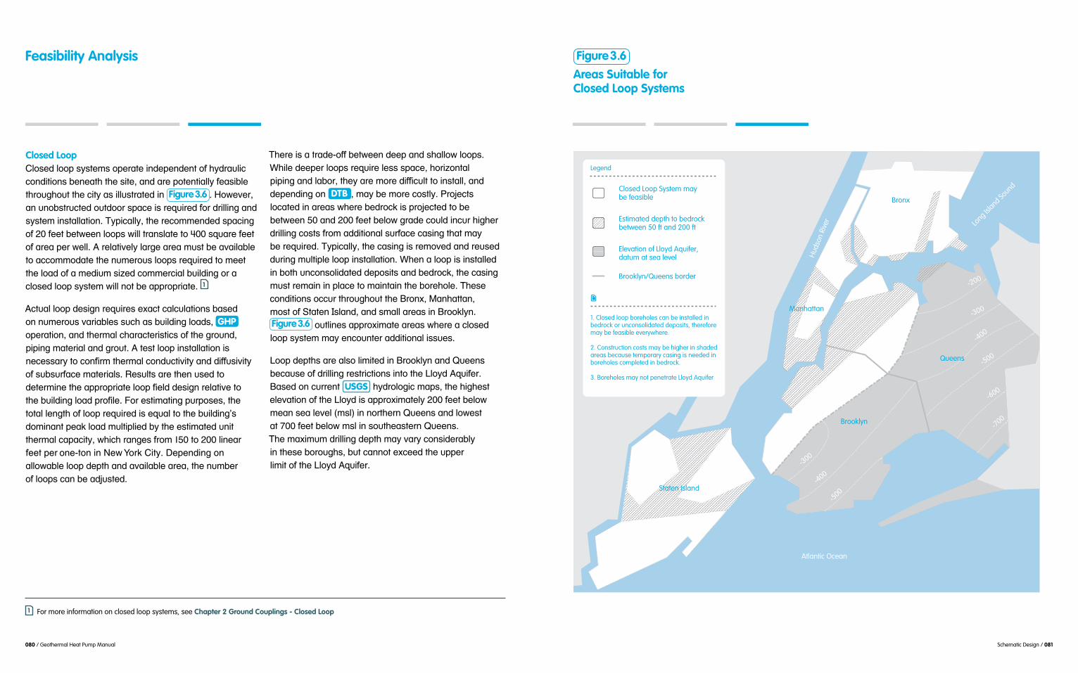
080 / Geothermal Heat Pump Manual Schematic Design / 081
Closed Loop''J35+*/'3550'+:+(*-+'50*#.(*'$%/*0*%/*%('54'):/#."3$,',5%/$($5%+';*%*.()'()*'+$(*1'.%/'.#*'05(*%($.33:'4*.+$;3*'()#5"&)5"('()*',$(:'.+'$33"+(#.(*/'$%' Figure 3.6 8'D5?*2*#1'.%'"%5;+(#",(*/'5"(/55#'+0.,*'$+'#*@"$#*/'45#'/#$33$%&'.%/'+:+(*-'$%+(.33.($5%8'A:0$,.33:1'()*'#*,5--*%/*/'+0.,$%&'54'MT'4**(';*(?**%'3550+'?$33'(#.%+3.(*'(5'`TT'+@".#*'4**('54'.#*.'0*#'?*338'>'#*3.($2*3:'3.#&*'.#*.'-"+(';*'.2.$3.;3*'(5'.,,5--5/.(*'()*'%"-*#5"+'3550+'#*@"$#*/'(5'-**('
,35+*/'3550'+:+(*-'?$33'%5(';*'.00#50#$.(*8' 1
>,(".3'3550'/*+$&%'#*@"$#*+'*<.,(',.3,"3.($5%+';.+*/''5%'%"-*#5"+'2.#$.;3*+'+",)'.+';"$3/$%&'35./+1' GHP '50*#.($5%1'.%/'()*#-.3',).#.,(*#$+($,+'54'()*'"%/1'0$0$%&'-.(*#$.3'.%/'"(8'>'(*+('3550'$%+(.33.($5%'$+'
'54'+";+"#4.,*'-.(*#$.3+8'Q*+"3(+'.#*'()*%'"+*/'(5'
''
(5(.3'3*%&()'54'3550'#*@"$#*/'$+'*@".3'(5'()*';"$3/$%&7+'/5-$%.%('0*.I'35./'-"3($03$*/';:'()*'*+($-.(*/'"%$('()*#-.3',.0.,$(:1'?)$,)'#.%&*+'4#5-'LST'(5'MTT'3$%*.#''4**('0*#'5%*B(5%'$%'G*?'H5#I'J$(:8'!*0*%/$%&'5%'.335?.;3*'3550'/*0()'.%/'.2.$3.;3*'.#*.1'()*'%"-;*#''54'3550+',.%';*'./6"+(*/8
A)*#*'$+'.'(#./*B544';*(?**%'/**0'.%/'+).335?'3550+8''
/*0*%/$%&'5%' DTB 1'-.:';*'-5#*',5+(3:8'E#56*,(+''35,.(*/'$%'.#*.+'?)*#*';*/#5,I'$+'0#56*,(*/'(5';*';*(?**%'ST'.%/'MTT'4**(';*35?'&#./*',5"3/'$%,"#')$&)*#'/#$33$%&',5+(+'4#5-'.//$($5%.3'+"#4.,*',.+$%&'().('-.:'';*'#*@"$#*/8'A:0$,.33:1'()*',.+$%&'$+'#*-52*/'.%/'#*"+*/'/"#$%&'-"3($03*'3550'$%+(.33.($5%8'9)*%'.'3550'$+'$%+(.33*/'$%';5()'"%,5%+53$/.(*/'/*05+$(+'.%/';*/#5,I1'()*',.+$%&'-"+('#*-.$%'$%'03.,*'(5'-.$%(.$%'()*';5#*)53*8'A)*+*',5%/$($5%+'5,,"#'()#5"&)5"('()*'=#5%<1'W.%).((.%1''
Figure 3.6 '5"(3$%*+'.00#5<$-.(*'.#*.+'?)*#*'.',35+*/'3550'+:+(*-'-.:'*%,5"%(*#'.//$($5%.3'$++"*+8
Z550'/*0()+'.#*'.3+5'3$-$(*/'$%'=#55I3:%'.%/'O"**%+';*,."+*'54'/#$33$%&'#*+(#$,($5%+'$%(5'()*'Z35:/'>@"$4*#8'=.+*/'5%',"##*%(' USGS '):/#535&$,'-.0+1'()*')$&)*+('*3*2.($5%'54'()*'Z35:/'$+'.00#5<$-.(*3:'MTT'4**(';*35?'-*.%'+*.'3*2*3'^-+3_'$%'%5#()*#%'O"**%+'.%/'35?*+(''.(']TT'4**(';*35?'-+3'$%'+5"()*.+(*#%'O"**%+8''A)*'-.<$-"-'/#$33$%&'/*0()'-.:'2.#:',5%+$/*#.;3:''$%'()*+*';5#5"&)+1';"(',.%%5('*<,**/'()*'"00*#''3$-$('54'()*'Z35:/'>@"$4*#8
'
Areas Suitable forClosed Loop Systems
Figure 3.6 TKFigure 3.6
Long Isl
and Sound
Huds
on R
iver
Atlantic Ocean
-200
-300
-300
-400
-500
-400
-500
-600
-700
Legend
Closed Loop System may be feasible
Elevation of Lloyd Aquifer, datum at sea level
Brooklyn/Queens border
Estimated depth to bedrock between 50 ft and 200 ft
1. Closed loop boreholes can be installed in bedrock or unconsolidated deposits, therefore may be feasible everywhere.
2. Construction costs may be higher in shaded areas because temporary casing is needed in boreholes completed in bedrock.
3. Boreholes may not penetrate Lloyd Aquifer
Bronx
Brooklyn
Manhattan
Queens
Staten Island
Feasibility Analysis
1 For more information on closed loop systems, see Chapter 2 Ground Couplings - Closed Loop

082 / Geothermal Heat Pump Manual Schematic Design / 083
Least efficient heat exchange with the ground because of insulating effect of plastic loop piping and grout backfill.
Highest drilling footage, number of wells, and construction cost compared to other systems.
Requires the most space and has the most site disturbance for trenching and piping compared to other systems.
May require an anti-freeze solution
Highest potential for conflicts with buried site utilities/structures.
Most reliable with the least maintenance compared to other GRCO types.
System performance and thermal capacity are not dependent on aquifer yield.
Not susceptible to scaling, corrosion, or biofouling because heat transfer fluid is isolated from contact with ground water.
Access to loops not required afterinstallation. Land over the loop fieldcan be used for other limited purposes.
No state or federal permits required if less than 500 ft. deep
J35+*/'3550'+:+(*-+'.#*'&*%*#.33:'$%+(.33*/'5"(/55#+'"+$%&',5%2*%($5%.3'/#$33$%&'*@"$0-*%(8'9)$3*'#*+(#$,(*/B.,,*++'#$&+'.#*'.2.$3.;3*'45#'$%+(.33$%&'3550+'?$()$%'.';"$3/$%&1'$%/55#'/#$33$%&'$+'+35?*#'.%/'-5#*',5+(3:8'
54'.'%*?';"$3/$%&'#*@"$#*+',.#*4"3'+:+(*-'.%.3:+$+'.%/',35+*#',55#/$%.($5%';*(?**%',5%(#.,(5#+8'
Advantages'A)*'-.$%'./2.%(.&*'54'.',35+*/'3550'+:+(*-'$+'().(''
'Figure 3.7 8'J35+*/'3550+'/5'%5(',#*.(*'/#.?/5?%'5#'-5"%/$%&'54'"%/'?.(*#'3*2*3+'().('-.:'.44*,('4"("#*'
*++*%($.3'45#'50*#.($5%1'$%+(.33$%&'3550+';*35?'()*'?.(*#'(.;3*'?$33'$%,#*.+*'()*'()*#-.3',.0.,$(:'.+'?.(*#'(*%/+'(5'$%,#*.+*'()*#-.3',5%/",($2$(:8'>3+51';*,."+*'()*'+:+(*-'$+'+*.3*/'544'4#5-'()*'+"##5"%/$%&'*%2$#5%-*%(1'$(',.%'';*'*-035:*/'$%'.#*.+'?$()'.&&#*++$2*'5#',5%(.-$%.(*/'"%/'?.(*#'().('5()*#?$+*'?5"3/';*'/*(#$-*%(.3''(5'5()*#'+:+(*-+8
'()*';"#$*/'0$0*+8'>4(*#'$%+(.33.($5%1'()*'.#*.'.;52*'()*'
'&#**%'+0.,*+1'0.#I$%&'.#*.+'.%/'5()*#'4"%,($5%+'().(''/5'%5('#*@"$#*'/**0'*<,.2.($5%+8'A)*+*'+:+(*-+',.%'';*'$%+(.33*/'$%'4#.,("#*/';*/#5,I'.+'35%&'.+'()*';5#*)53*'
Disadvantages'
+:+(*-+';*,."+*'54'()*'()*#-.3'#*+$+(.%,*'5#'$%+"3.($%&'*44*,(',#*.(*/';:'()*'03.+($,'0$0*+'.%/'"(8'P2*%'()5"&)'()*#-.33:'*%).%,*/'"('$%,#*.+*+',5%/",($2$(:1'()*'
()*';"$3/$%&'.%/'"%/'$+'$%/$#*,(8'C#*.(*#'3550'3*%&()'.%/'3.%/'.#*.'$+'#*@"$#*/'(5'0#52$/*'()*'+.-*''()*#-.3',.0.,$(:8
A)*+*'+:+(*-+',.%';*'-5#*'*<0*%+$2*'().%'50*%'3550'+:+(*-+';*,."+*'54'()*'.//$($5%.3'/#$33$%&'.%/'-.(*#$.3+'$%2532*/8'A)*'(:0$,.3';5#*)53*'/*0()'54'STT'4**('$+'/**0*#'().%'()*'?*33+'$%'.%'50*%'3550'+:+(*-1'.3()5"&)'
SCW 8'D5?*2*#1',5%+$/*#.;3:'-5#*';5#*)53*+'.#*'#*@"$#*/'(5'.,)$*2*'.%'*@"$2.3*%(',.0.,$(:',5-0.#*/'(5'.%'50*%'3550'5#'[J9'+:+(*-8'HDPE '0$0$%&'$%'*.,)';5#*)53*'?$33'.3+5'$%,#*.+*'-.(*#$.3'.%/'3.;5#',5+(+1'?)$,)'#*@"$#*'(*+($%&'54'()*'"('.%/'0$0*',$#,"$(+'45#'0#50*#'$%+(.33.($5%8
Feasibility AnalysisAnalysis of Closed Loop System
Advanta
ges
Disadva
ntages
Syste
m
Con
sidera
tions
Range in thermal capacity for a 500 ft. deepwell is 2.5–3.3 tons (30–40 MBH) of heat transfer capacity.
Recommended minimum loop spacing is 20 ft., or 400 sq ft. of land area required per loop. Typical depth is 200–500 ft.
Loop depth and number depend on load profile, available land area, depth to bedrock, and drilling conditions.
A test loop and thermal conductivity testing is essential for larger than 25 loop system. One test loop per 50 loops is recommended.
Loops can be installed in either unconsolidated deposits or bedrock.
Figure 3.7

084 / Geothermal Heat Pump Manual Schematic Design / 085
Open Loop'U0*%'3550'+:+(*-+'#*@"$#*')$&)3:'0#5/",($2*1'0*#-*.;3*'.@"$4*#+'+",)'.+'()5+*'45"%/'$%'=#55I3:%'.%/'O"**%+8'
-.:'.3+5';*'+"$(.;3*1'.+'+)5?%'$%' Figure 3.8 8'>'+$(*7+'):/#5&*535&:'$+'*<(#*-*3:',#$($,.3'(5'+:+(*-'/*+$&%';*,."+*')*.('*%*#&:'$+'(#.%+4*##*/'/$#*,(3:'4#5-'"%/'?.(*#8'>@"$4*#'0#50*#($*+'+",)'.+'DTW '.%/'/$#*,($5%'54'
2
E#*3$-$%.#:'):/#."3$,',.3,"3.($5%+'"+$%&'0";3$+)*/'''
.%/'.%.3:+$+'(5'2*#$4:'.,(".3',).#.,(*#$+($,+'+",)'.+''
0"-0$%&'(*+('.%/'.';5#*)53*'&*50):+$,.3'+"#2*:'?$33''
35./+'.%/')*30'/*(*#-$%*'?*33'/*+$&%'+",)'.+'+0.,$%&1''
.'&*535&$+(',533*,(+'.%/'35&+';5#$%&+';*45#*'+*%/$%&''(5'.'3.;5#.(5#:'$+'.3+5'%*,*++.#:'(5'/*(*#-$%*'+,#**%'
Areas Suitable for Open Loop Systems
Figure 3.8 Areas Where Open Loop Systems May Be FeasibleFigure 3.7
Long Isl
and Sound
Huds
on R
iver
Atlantic Ocean
Bronx
Brooklyn
Queens
Manhattan
Staten Island
Legend
Open Loop System may be feasible
1. Suitability based on presence of potentially high-yielding sand and gravel deposits.
2. Suitability depends on acceptablewater quality.
3. Shoreline areas may not be suitable because of brackish or salty ground water.
4. Conditions may not be suitable in northern Queens because of limited aquifer thickness.
5. Feasibility must be confirmed by a test well and ground water sampling.
6. Lloyd Aquifer in Brooklyn and Queenscannot be used for geothermal purposes.
Open Loop System not feasible
Brooklyn/Queens border
Feasibility Analysis
E#*3$-$%.#:'"%/'?.(*#'+.-03$%&'.%/'.%.3:+$+''+)5"3/'.3+5';*'0*#45#-*/'0#$5#'(5'+*3*,($%&'.%'50*%''
'+",)'.+'(*-0*#.("#*1'0D'3*2*3+'.%/'("#;$/$(:'?)$3*'5()*#'',#$(*#$.'+",)'.+'253.($3*'5#&.%$,',5-05"%/+1').#/%*++''
3.;5#.(5#:8'>%'*<0*#$*%,*/'):/#5&*535&$+('5#'&*5B'
45#'+,.3$%&1';$545"3$%&1'.%/',5##5+$5%8'E5(*%($.3',5##5+$2*',5%/$($5%+'+)5"3/'.3*#('/*+$&%*#+'(5'"+*'03.+($,'0$0$%&'
'0$0$%&'54'/$++$-$3.#'-*(.3+8'U()*#'GRCO '(:0*+'+)5"3/'';*'#*2$*?*/'$4'"%/'?.(*#'@".3$(:'$+'"%.,,*0(.;3*8
U0*%'3550'+:+(*-+'#*@"$#*'()*'3*.+('.-5"%('54''/#$33$%&',5-0.#*/'(5'5()*#'CQJU+8'A:0$,.33:1'5%*''
#*@"$#*+'(?5'/$44"+$5%'?*33+'45#'*.,)'+"003:'(5'#*("#%''?.(*#';.,I'(5'()*'.@"$4*#8'D5?*2*#1'.'0#56*,('+$(*''-.:'%5(';*'.00#50#$.(*'$4'?*33'35,.($5%+'.%/'-$%$-"-'+0.,$%&',.%%5(';*'.,,5--5/.(*/8
2 For more information on open loop systems, see Chapter 2 Ground Couplings - Open Loop

Thermal capacity depends on ground water flow rate and ranges from 1.5–2 gallons per minute per ton or 12 MBH.
Well depth and spacing depend on hydraulic conditions, pumping rates, duration, and regulatory requirements.
Wells should be screened in permeable, unconsolidated deposits. Bedrock generally not suitable.
Sampling is critical to confirm ground water quality before finalizing selection.
A minimum of one test well and a pumping test are critical for design purposes and well layout.
Backup well(s) to maintain system operation during servicing is recommended.
Most susceptible to scaling, corrosion, and/or biofouling from contact with poor ground water quality.
Highest well maintenance.
Maintaining minimum spacing between supply and diffusion wells to avoid hydraulic or thermal interference may not be possible.
Excessive ground water pumping can affect water levels in nearby water supply or other geothermal wells.
Requires future access to well head for pump and well servicing.
Federal, state and local permits required. Permit may be denied if ground water is contaminated.
Most efficient system because of direct thermal exchange with ground water at ambient temperature.
Least amount of drilling and lowest installation costs.
Smallest amount of well installations, piping, trenching, footprint, and site disturbances.
Anti-freeze not used.
Standard well drilling and construction methods used.
Smallest amount of potential for conflicts with buried site utilities or structures.
086 / Geothermal Heat Pump Manual Schematic Design / 087
Advantages '
3*++'*<0*%+$2*'(5'$%+(.33'().%'()*'5()*#'GRCO '(:0*+1''' Figure 3.9 8'A)*#-.3'*<,).%&*'
).00*%+'$--*/$.(*3:'?$()'.-;$*%('(*-0*#.("#*'"%/'
?$()'4*?*#'?*33+8'A:0$,.33:'$%'=#55I3:%'.%/'O"**%+1'5%*'+"003:'?*33'$+'"+*/'45#'.'LTTB(5%'35./1'0#52$/*/'().('
\*?*#'?*33+'(#.%+3.(*'$%(5'35?*#'/#$33$%&',5+(+'.+''?*33'.+'35?*#',5+(+'45#'0$0$%&1'(#*%,)$%&1'.%/'0"-0+8''[$%,*'()*#*'.#*'4*?*#'+:+(*-',5-05%*%(+1'3*++'+$(*'
*<$+('?$()'5()*#'"%/*#"%/'+:+(*-+';*,."+*'54''()*'+:+(*-7+'+-.33*#'455(0#$%(8
Disadvantages'>3()5"&)'/$#*,(3:'"+$%&'"%/'?.(*#'$%,#*.+*+'
',5-03:'?$()'#*&"3.(5#:'3$-$(+'45#'0*#-$(($%&8'D5?*2*#1'*2*%'?$()$%'#*&"3.(*/'3$-$(+1'5#&.%$,'.%/'$%5#&.%$,',5-05"%/+'.+'?*33+'.+',*#(.$%'(:0*+'54';.,(*#$.'$%''()*'.@"$4*#',.%'#*+"3('$%';$545"3$%&1',5##5+$5%1'+,.3$%&''5#'$#5%'0#*,$0$(.($5%'5%'+:+(*-',5-05%*%(+8
C#5"%/'?.(*#',5%/$($5%+'.#*'+";6*,('(5',).%&*''45#'#*.+5%+';*:5%/'()*';"$3/$%&'5?%*#7+',5%(#538'G*$&);5#$%&'4.,$3$($*+'-.:'/*,$/*'(5'$%+(.33'.%/''50*#.(*'+$-$3.#'&*5()*#-.3'+:+(*-+'5#'+"003:'?*33+1'
;*%*.()'()*'0#50*#(:'.%/'.3(*#'()*'"%/'?.(*#'(*-0*#.("#*8'A)*'$-0.,('54'+",)',).%&*+'-"+(';*',5%+$/*#*/1'*+0*,$.33:'$%'.')$&)3:'"#;.%'*%2$#5%-*%('?)*#*'./6.,*%('0#50*#($*+'.#*',35+*3:'+0.,*/8
U0*%'3550'+:+(*-+',.%'.3+5').2*')$&)*#'50*#.($5%''.%/'-.$%(*%.%,*',5+(+8'>,,*++'(5'?*33+'$+'%*,*++.#:''45#'4"("#*'+*#2$,$%&1'$%,3"/$%&'()*'+";-*#+$;3*'0"-0+8'J5+(3:'?*33'#*).;$3$(.($5%'-.:';*'#*@"$#*/'/*0*%/$%&''5%',5%/$($5%+'?$()$%'()*'.@"$4*#'.%/'()*'*44*,('5%'()*''+,#**%+'.%/'0"-0+8
Analysis of Open Loop System
Can be configured as hybrid system with boilers or passive solar thermal system to supplement heat-ing demand, and cooling towers or dry cooler to supplement cooling demand.
Advanta
ges
Disadva
ntages
Syste
m
Con
sidera
tions
Feasibility Analysis Figure 3.9

088 / Geothermal Heat Pump Manual Schematic Design / 089
Standing Column Wells'[(.%/$%&',53"-%'?*33+'#*3:'5%',5%/",($2*')*.('(#.%+4*#';*(?**%',$#,"3.($%&'"%/'?.(*#'.%/';*/#5,I8''>'+).335?*#' DTB '?$33'0#52$/*'&#*.(*#'()*#-.3',.0.,$(:'
'.33'54'=#5%<1'W.%).((.%'?$()'*<,*0($5%+'$%'()*'+5"()''
.#*.+'$%'%5#()*#%'=#55I3:%'.%/'O"**%+1'.+'+)5?%''$%' Figure 3.10 8'>#*.+'?$()'!A='&#*.(*#'().%'LTT'4**(''?$33'$%,#*.+*',5+(+1'?)$,)'$-0.,(+'()*'2$.;$3$(:'54''.%' SCW 8' 3
>'-.<$-"-'DTW '54'LTT'4**('$+'.3+5'&*%*#.33:'#*,5-B
!A9',5##*3.(*'?$()')$&)'+"#4.,*'*3*2.($5%+1'$%,3"/$%&'
GHP '$%'()5+*'.#*.+'-.:';*'%*&.(*/';:'*%*#&:'+0*%('5%'0"-0$%&8
-*%/*/'-$%$-"-'+0.,$%&'54'ST'(5']S'4**('$+'-.$%(.$%*/8'>3+51',5-0*(*%(';*/#5,I'(5'()*';5((5-'54'()*'?*33'$+'%**/*/'45#'()*';5#*)53*'(5';*'+*34B+"005#($%&8'U()*#?$+*1'.//$($5%.3',.+$%&'-.:';*'#*@"$#*/'.%/'$%,#*.+*'0#56*,(',5+(+8'>,,*++'45#'4"("#*'+*#2$,$%&'+)5"3/'.3+5';*',5%+$/*#*/'.%/'5"(3$%*/'/"#$%&'/*+$&%8'
:$*3/'.%/'-"+('/$+,).#&*'?.(*#'(5'.'+"$(.;3*'35,.($5%1'+",)'.+'/*/$,.(*/'/$44"+$5%'?*33+'5#'+"#4.,*'?.(*#'$-05"%/-*%(+8'Q*"+*'$%'%5%B05(.;3*'.003$,.($5%+''
+",)'.+'$##$&.($5%'5#',553$%&'(5?*#'-.I*B"0'?.(*#''$+'.3+5'#*,5--*%/*/'+$%,*';3**/'?.(*#',.%%5(';*'/$+,).#&*/'(5'()*',$(:'+*?*#'+:+(*-'0*#' NYCDEP '
'+)5?'#*3.($2*3:'35?'+"+0*%/*/'+53$/+'.%/'-$%*#.3B
'5#&.%$,'0533"(.%(+1'.%/'.'%*"(#.3'0D8
Advantages [J9+'-.$%(.$%',*#(.$%'./2.%(.&*+'52*#'5()*#''
Figure 3.11 8'9)$3*'50*%''3550'+:+(*-+'#*@"$#*')$&)3:'0#5/",($2*'.@"$4*#+1''[J9+'50*#.(*'?$()'-$%$-.3'"%/'?.(*#'4#5-''4#.,("#*/';*/#5,I8'P.,)'?*33'$+'.3+5'$+53.(*/'4#5-'52*#3:$%&'"%,5%+53$/.(*/'/*05+$(+';:'.'0*#-.%*%(''+(**3',.+$%&8'J5%+*@"*%(3:1'[J9+'%5#-.33:'/5''%5('/$#*,(3:'.44*,('%5#'.#*'()*:'.44*,(*/';:''52*#3:$%&'.@"$4*#+8
9)*%',5-0.#*/'(5'.',35+*/'3550'+:+(*-1'.' SCW '''
,$#,"3.($%&'"%/'?.(*#',5-*+'/$#*,(3:'$%(5',5%(.,(''?$()'()*';*/#5,I8'U%*'?*33',.%'0#52$/*';*(?**%''LT'.%/'MT'($-*+'-5#*'()*#-.3',.0.,$(:'().%'.'+$%&3*',35+*/'3550'?*338'!*+0$(*'&#*.(*#'/*0()+1'()*'(5(.3'.-5"%('54'/#$33$%&'#*@"$#*/'$+'+";+(.%($.33:'3*++1'?)$,)'#*+"3(+'$%'35?*#'$%+(.33.($5%',5+(+8'>'+-.33*#'%"-;*#''54'?*33+'.3+5',5%+"-*+'3*++'.#*.'.%/',.%';*'-5#*'*.+$3:'$%(*&#.(*/'$%(5'()*'52*#.33'+$(*'3.:5"(8
Areas Suitable for Standing Column Well Systems
Figure 3.10
Long Isl
and Sound
Huds
on R
iver
Atlantic Ocean
Brooklyn
Queens
Bronx
Manhattan
Legend
1. SCW’s are cost prohibitive and technically infeasible where depth to bedrock exceeds 200 ft.
2. SCW surface casing installation cost increases where depth to bedrock exceeds 100 ft.
3. Higher pumping energy costs may occur where depth to ground water exceeds 100 ft.
Standing Column Wells may be suitable – estimated depth to bedrock less than 100 ft.
Standing Column Wells not suitable – estimated depth to Bedrock greater than 200 ft.
Estimated depth to ground water may be greater than 100 ft.
Estimated depth to Bedrock between 100 and 200 ft.
Staten Island
Feasibility Analysis
3 For more information on SCW, see Chapter 2 Ground Couplings - Standing Column Well

Range in thermal capacity for a 1,500 ft. well is 15–42 tons (180–500 MBH) of heat transfer capacity.
Recommended minimum well spacing is 50–75 ft.
Well depth depends on building load and number of wells that can be located on the site. Typical depth is 1,500 ft.
Test well is advisable for systems with 8 or more wells. May not be cost-effective for smaller systems.
Should include a contingency for additional and/or deeper wells if actual well yields are less than design bleed flow rate.
Optimal conditions include a shallowDTB, generally less than 100 ft.
Bedrock with moderate yields for bleed provide highest capacity, but requires suitable discharge location for bleed water.
Generally highest installation cost ofall systems.
Higher well maintenance than closedloop, but less than open loop.
Susceptible to scaling, corrosion, and/orbiofouling, but less than open loop.
Ground water drawdown during bleedcycles can affect water levels in nearbysupply wells or other geothermal wells,but less than open loop.
Susceptible to sediment in return water. Potentially susceptible to water circulation problems because of sedimentation around shroud.
Susceptible to return flow balancingissues if multiple wells are combinedinto single manifold.
Requires future access to well headfor servicing.
State and federal permits required.
090 / Geothermal Heat Pump Manual Schematic Design / 091
Analysis of Standing Column Well System
Advanta
ges
Disadva
ntages
Syste
m
Con
sidera
tions
Significantly higher thermal capacity per well installation than closed loop, but less than open loop.
Significantly less drilling required than closed loop system, resulting in less piping, trenching, and site disturbance.
Flexible well locations, maintain 50–75 ft. spacing minimum
No anti-freeze used.
Can be configured as hybrid system with boilers or passive solar thermal system to supplement heating demand, and cooling towers or dry cooler to supplement cooling demand.
Disadvantages SCW '+:+(*-'-.:'$%,"#'()*')$&)*+('
,5%+(#",($5%',5+(8'!#$33$%&'$+'+35?*#1'3.#&*#'$%'/$.-*(*#1'.%/'$%2532*+'$%+(.33$%&'.',.+$%&'$%(5';*/#5,I8'P<0*#$*%,*').+'+)5?%'().('()*'+(**3',.+$%&'$%+(.33.($5%'.,,5"%(+'45#'.+'-",)'.+'5%*B()$#/'54'()*'(5(.3',5+(1'*2*%'()5"&)'()*',.+$%&'$+'3*++'().%'LT'0*#,*%('54'()*'(5(.3'?*33'/*0()8'C#5"%/'?.(*#'@".3$(:',.%'.3+5';*'.',5%,*#%1'.%/'.+''.'#*+"3(1'50*#.($5%'.%/'-.$%(*%.%,*',5+(+'.#*'&*%*#.33:')$&)*#'().%',35+*/'3550'+:+(*-+8
A)*#-.3',.0.,$(:'$+'&#*.(*+('45#';5#*)53*+'().('$%(*#+*,('?.(*#';*.#$%&'4#.,("#*+1'.335?$%&'45#'05(*%($.3';3**/8'D5?*2*#1'/#$33$%&'()#5"&)')$&)3:'4#.,("#*/';*/#5,I').+')$&)*#'05(*%($.3'45#'"%+(.;3*'+$/*?.33+'.%/',533.0+$%&'
52*#'($-*'45#'-.(*#$.3'(5'+**0'$%(5'()*';5((5-'54'()*'?*33'.%/'$-0.,('?.(*#',$#,"3.($5%'$%'()*'.%%"3"+8
>'(*+('?*33'(5'2*#$4:'+$(*',5%/$($5%+'-.:'%5('%*,*++.#$3:';*'#*0#*+*%(.($2*'54'.33'/#$33$%&'35,.($5%+'+$%,*'2.#$.B'($5%+',.%'*<$+('*2*%'52*#'+)5#('/$+(.%,*+8'=*,."+*'54'2.#$.;$3$(:'$%'()*'+";+"#4.,*'*%2$#5%-*%(1'?*33':$*3/'$+')$&)3:'$##*&"3.#'?$()'+5-*'?*33+'0*#45#-$%&';*((*#'().%'5()*#+8'>+'.'#*+"3(1'-"3($03*1'35?':$*3/$%&'?*33+'-.:'%*,*++$(.(*'-5#*'$%+(.33.($5%+'(5'-**('()*';"$3/$%&''35./+'().%'5#$&$%.33:'03.%%*/8'P2*%'?)*%'.'(*+('?*33''$+'+",,*++4"31'()*#*'$+'+5-*'#$+I'().('()*'&*535&:'.(''5()*#'?*33'35,.($5%+'-.:'/$44*#'*%5"&)'().('()*:'.#*''%5('50($-.3'45#'.'[J9'+:+(*-8
[$-$3.#'(5'5()*#'CQJU+1'-5+('54'()*+*'/$+./2.%(.&*+',.%';*'.//#*++*/'/"#$%&'()*'/*+$&%'0).+*'5#'()#5"&)',5%($%&*%,:'-*.+"#*+'$-03*-*%(*/'/"#$%&',5%+(#",($5%8'\5#'*<.-03*1'$4'"%/'?.(*#'@".3$(:'$+'@"*+($5%.;3*1'.//$%&'.'03.(*B4#.-*')*.('*<,).%&*#'$%(5'()*'/*+$&%''
/5,"-*%(+'+)5"3/'$%,3"/*'.3(*#%.(*'3$%*'$(*-+'45#',5%($%&*%,:'.,($2$($*+'+",)'.+'$%+(.33.($5%'54'0*#-.B'
Feasibility AnalysisFigure 3.11

092 / Geothermal Heat Pump Manual Design / 093
Design
44.0List of Abbreviations
COP
EER EWT
HX
AHU FCU
SCW VFD
BMS
GHP
HTF
ODP
Coefficient of Performance
Energy Efficiency Ratio
Entering Water Temperature
Air Handling Unit Fan Coil Unit
Standing Column Well Variable Frequency Drive
Building Management System
Geothermal Heat Pump
Heat Transfer Fluid
Ozone Depletion Potential
GRCO
HCFC HDPE HVAC
Ground Coupling
Hydrochlorofluoro-carbons
High-Density Polyethylene
Heating, Ventilation, and Air Conditioning
Heat Exchanger

094 / Geothermal Heat Pump Manual Design / 095
GHP !"#"$%&!'%"()*!("!"(&(+,-!$.!'%"()*"!/.-!0.*1%*$(.*,+!HVAC !%23(4&%*$5!6*!67896:!;,"%'!&%$<.'!./!<%,$(*)!,*'!0..+(*)!+.,'!,*,+#"("!("!-%23(-%'!$.!4-.4%-+#!"(=%!%23(4&%*$!,*'!.4$(&(=%!'("$-(;3$(.*!/.-!;3(+'(*)!"4,0%"!"%-1%'5!8.>%1%-?!"(*0%!@8A!3*($"!-%+#!.*!<%,$!%B0<,*)%!>($<!$<%!)-.3*'?!GRCO !'%"()*!>(++!-%23(-%!"4%0(,+(=%'!%B4%-$("%!*.$!0.&&.*!$.!0.*1%*$(.*,+!8C6D!%23(4&%*$5
6*!,003-,$%!+.,'!,*,+#"("!("!4,-$(03+,-+#!0-($(0,+!/.-!4-.4%-+#!"(=(*)!$<%!@9DE5!6+$<.3)<!$<%-%!,-%!0."$"!!,*'!.4%-,$(.*,+!(""3%"!,//%0$(*)!;.$<!0.*1%*$(.*,+!,*'!@8A!"#"$%&"?!-3+%F./F$<3&;!0,+03+,$(.*"!0,*!<,1%!,!)-%,$%-!'%$-(&%*$,+!(&4,0$!.*!@8A!"#"$%&"5!G<%*!8C6D!%23(4&%*$!.-!,!@9DE!("!.1%-"(=%'!;,"%'!.*!%"$(&,$%'!4%,H!+.,'!-%23(-%&%*$"!,*!(*0-%,"%!(*!0,4($,+!0."$"!0,*!.003-!'%4%*'(*)!.*!$<%!@9DE!$#4%5!I<%!
!$.!$<%!4-.J%0$!;3')%$!.>(*)!$.!%B$-,!'-(++(*)5
D.*1%-"%+#?!,*!3*'%-"(=%'!@8A!"#"$%&!>(++!-%"3+$!!(*!-%'30%'!0,4,0($#!.-!%1%*!+%,'!$.!/,(+3-%!(/!0.*$(*3,++#!.4%-,$%'!;%#.*'!'%"()*!0,4,0($#5!G($<!+(&($%'!.4$(.*"!!/.-!0,4,0($#!,'J3"$&%*$?!0.--%0$(*)!,*!3*'%-"(=%'!@9DE!>(++!;%!&.-%!%B4%*"(1%!(*!$<%!+.*)!$%-&5!D.*"%23%*$+#?!<%,$(*)!,*'!0..+(*)!+.,'!,*,+#"("!"<.3+'!;%!0,-%/3++#!4%-/.-&%'!$.!4-.'30%!,!@9DE!'%"()*!$<,$!;%$$%-!!&,$0<%"!$<%!;3(+'(*)K"!*%%'"5!
4.1 GHP System Design
4.2 Load Analysis and Sizing
!$%"$(*)?!'%"()*(*)!$<%!@9DE!("!*.$!,!"(&4+%!4-.0%""!;,"%'!.*!,!"(*)+%!0,+03+,$(.*5!7(*0%!'%"()*!(*43$"!!,-%!,""3&4$(.*"!;,"%'!.*!<("$.-(0,+!>%,$<%-!',$,!,*'!
1,-(,$(.*!.*0%!$<%!;3(+'(*)!("!.0034(%'!,*'!(*!.4%-,$(.*5!L,$3-,+!1,-(,$(.*"!(*!$<%!$<%-&,+!,*'!<#'-,3+(0!4-.4%-$(%"!
,//%0$!$<%!@9DE!'%"()*5!M.-!(*"$,*0%?!(/!)-.3*'!>,$%-!!("!4-%"%*$?!$<%!$<%-&,+!0,4,0($#!&,#!;%!(*0-%,"%'!/.-!0+."%'!+..4!,*'!7DG!"#"$%&"!,*'!'-(++(*)!'%4$<"!&,#!!;%!-%'30%'5!8.>%1%-?!,++.>(*)!/.-!(*0-%,"%'!0,4,0($#!
%B$%*'!(*$.!$<%!'%"()*!/,0$.-!./!",/%$#5
Equipment and GRCO Sizing!7(&(+,-+#?!,!&%0<,*(0,+!%*)(*%%-!>(++!$#4(0,++#!%1,+3,$%!;3(+'(*)!+.,'"!,*'!"%+%0$!$<%!,44-.4-(,$%!%23(4&%*$?!!"(=%'!$.!&%%$!$<%!%"$(&,$%'!4%,H!'%&,*'5!8.>%1%-?!"(=(*)!$<%!GRCO !("!,!"%4,-,$%!4-.0%""!,*'!>(++!'%4%*'!.*!$<%!"#"$%&!$#4%!,"!0+."%'!+..4!"#"$%&"!>(++!<,1%!!)-%,$%-!-%23(-%&%*$"!$<,*!.4%*!+..4!"#"$%&"5!G<(+%!!-3+%F./F$<3&;!%"$(&,$%"!,*'!%*)(*%%-(*)!%23,$(.*"!,-%!,1,(+,;+%!/.-!4-%+(&(*,-#!,*,+#"("?!,!"300%""/3+!@9DE!
!$<%-&,+!0.*'30$(1($#?!"3"$,(*,;+%!>%++!#(%+'?!,*'!,1,(+,;+%!EWT 5!6!)%.$<%-&,+!%*)(*%%-!.-!,!&%0<,*(0,+!%*)(*%%-!>($<!$<%!-%23("($%! GHP !"#"$%&!%B4%-(%*0%!>(++!(*0+3'%!!$<%"%!/,0$.-"!(*!'%$%-&(*(*)!$<%!@9DE!"(=%?!'%4$<!,*'!+,#.3$!*%%'%'!$.!&%%$!'%&,*'5
6*!,003-,$%!+.,'!,*,+#"("!;%)(*"!>($<!,!0+."%!%B,&(*,$(.*!./!$<%!;3(+'(*)?!($"!+.0,$(.*!,*'!3"%5!M,0$.-"!$.!(*1%"$(),$%!,*'!'%$%-&(*%!(*0+3'%!.3$'..-N(*'..-!'%"()*!0.*'($(.*"?!;3(+'(*)!0.*"$-30$(.*?!.-(%*$,$(.*?!0+(&,$%?!.0034,*0#!!,*'!"0<%'3+%!./!3"%5!O3(+'(*)"!>(++!<,1%!,*!,**3,+!+.,'!
$<-.3)<.3$!,!$#4(0,+!#%,-!,"!>%++!,"!4%,H!+.,'"!$<,$!.003-!'3-(*)!4%,H!'%&,*'!4%-(.'"?!"30<!,"!"3&&%-!".+,-!!),(*"!.-!%B$-%&%!>(*$%-!$%&4%-,$3-%"5!
74,0%!0.*'($(.*(*)!"#"$%&"!,-%!$#4(0,++#!"(=%'!$.!!&%%$!$<%!4%,H!+.,'?!%1%*!$<.3)<!$<%!%23(4&%*$!!>(++!.4%-,$%!>%++!;%+.>!$<%!4%,H!'%&,*'!/.-!&30<!./!!$<%!$(&%5!P/!;.$<!<%,$(*)!,*'!0..+(*)!,-%!4-.1('%'?!$<%!!4%,H!'.&(*,*$!+.,'!>(++!'%$%-&(*%!$<%!"(=%!./!$<%!%23(4&%*$!,"!>%++!,"!$<%!GRCO !/.-! GHP !"#"$%&"5!
GRCO Systems and Loads 6! GHP !3*($!("!,!>,$%-F".3-0%!<%,$!43&4!,*'!&3"$!&,(*$,(*!,*!.4$(&,+!-,*)%!./!entering water temperatures!EWT 1 5!M.-!0+."%'!+..4!,*'! SCW !"#"$%&"?!:GI!("!'%4%*'%*$!.*!<%,$!%B0<,*)%!>($<!$<%!)-.3*'!4-(&,-(+#!$<-.3)<!0.*'30$(.*5!I<%!$.$,+!+..4!!+%*)$<!.-!>%++!'%4$<!,1,(+,;+%!("!'(-%0$+#!4-.4.-$(.*,+!$.!!$<%!,&.3*$!./!<%,$!%B0<,*)%!-%23(-%'5!D.*"%23%*$+#?!><%*!+.,'!,*,+#"%"!'.!*.$!,003-,$%+#!,00.3*$!/.-!;3(+'(*)!0.*'($(.*"!.-!3"%"?!$<%!GRCO !"#"$%&!>(++!;%!(&4-.4%-+#!"(=%'?!-%"3+$(*)!(*!%($<%-!)-%,$%-!(*"$,++,$(.*!0."$"!.-!-%'30%'!"#"$%&!4%-/.-&,*0%5!E4%*!+..4!"#"$%&"!,-%!
,*!.4$(&,+!:GI!-,*)%!-,$<%-!$<,*!$<%-&,+!0.*'30$(.*5!6+$<.3)<!,''($(.*,+!"344+#!>%++"!&,#!;%!*%%'%'?!$<%!!
!><(0<!<,"!,!+%""%-!0."$!(&4,0$5!
1 For more information on GHP units, see Chapter 2 Geothermal Heat Pumps.

096 / Geothermal Heat Pump Manual Design / 097
Load Imbalances!G($<!$()<$%-!;3(+'(*)!%*1%+.4%"!,*'!<()<%-!+()<$(*)!!+.,'"?!&."$!0.&&%-0(,+!,*'!(*"$($3$(.*,+!;3(+'(*)"!,-%!!(*!-%,+($#!0..+(*)!'.&(*,*$5!D.*"%23%*$+#?!$<%!0..+(*)!+.,'"!,-%!&.-%!./$%*!)-%,$%-!$<,*!$<%!<%,$(*)!'%&,*'?!,*'!$<%"%!;3(+'(*)"!>(++!$%*'!$.!-%J%0$!&.-%!<%,$!(*$.!!$<%!)-.3*'!$<,*!($!-%&.1%"!.*!,*!,**3,+!;,"("5!I<%!GRCO !&3"$!;%!'%"()*%'!$.!<,*'+%!,*!(&;,+,*0%'!+.,'!0.*'($(.*?!4,-$(03+,-+#!(*!0+."%'!+..4!,*'! SCW !"#"$%&"5!
'%"()*%'!.4%*!+..4!"#"$%&!><%-%!"344+#!,*'!'(//3"(.*!
I<%!-%/-()%-,$(.*!0#0+%!3"%'!(*!$<%!<%,$!43&4!,+".!0.*$-(;3$%"!$.!,!+.,'!(&;,+,*0%5!Q3-(*)!<%,$(*)?!$<%!@9DE!.*+#!*%%'"!$.!4-.1('%!,44-.B(&,$%+#!RST!./!!$<%!<%,$(*)!+.,'!-%23(-%'!"(*0%!<%,$!)%*%-,$%'!;#!$<%!GHP !&.$.-"!0,*!;%!-%0.1%-%'!/.-!"4,0%!0.*'($(.*(*)5!8.>%1%-?!$<%!@9DE!>(++!*%%'!$.!,;".-;!;.$<!$<%!<%,$!-%J%0$%'!/-.&!$<%!;3(+'(*)!,*'!$<%!<%,$!)%*%-,$%'!;#!!$<%!&.$.-"?!><(0<!("!,44-.B(&,$%+#!UVFWST!<()<%-!$<,*!!$<%!0..+(*)!+.,'5!I<%!+.,'!(&;,+,*0%!,+-%,'#!(*!0..+(*)!'.&(*,*$!;3(+'(*)"!("!$<%-%/.-%!/3-$<%-!%B,0%-;,$%'5
P/!,!0..+(*)!+.,'!(&;,+,*0%!("!*.$!,''-%""%'?!$<%!!@9DE!&,#!*.$!;%!,;+%!$.!%//%0$(1%+#!'(""(4,$%!%B0%""!<%,[email protected]*'!$%&4%-,$3-%"!>(++!-("%!.1%-!$(&%!,*'!!+%,'!$.!,!"$%,'#!(*0-%,"%!(*! EWT 5!6"!$%&4%-,$3-%"!
Load Analysis and Sizing
I<%!@9DE!'%"()*!&,#!;%!,;+%!$.!,00.&&.',$%!!"&,++%-!(&;,+,*0%"!$<-.3)<!'%%4%-!>%++"!.-!)-%,$%-!"4,0(*)!./!;.-%<.+%"!,*'!>%++"5!P/!$<%-%!("!%B0%""(1%!!<%,$!-%J%0$(.*!$.!$<%!)-.3*'?!(*$%)-,$(*)!,!0..+(*)!!
".&%!./!$<%!(&;,+,*0%5!I<%!'%"()*!$%,&!"<.3+'!-%1(%>!;.$<!.4$(.*"!,"!4,-$!./!"#"$%&!'%"()*!-,$<%-!$<,*!!>,($(*)!/.-!.4%-,$(.*,+!(""3%"!$.!'%1%+.45!
!
8.-(=.*$,+?!1%-$(0,+?!0.*".+%?!"4+($?!,*'!"$,0H%'!3*($"!!,-%!-%,'(+#!,1,(+,;+%!(*!,!>('%!-,*)%!./!+.,'!0,4,0($(%"5!X9()<$K!"(=(*)!,1.('"!"<.-$!0#0+(*)?!$<%-&,+!0.&/.-$!
%23(4&%*$5!Q(&%*"(.*"!1,-#!>($<!0,4,0($#?!,*'!!
/-%"<!,(-!'%1(0%"!0,*!;%!(*$%)-,$%'5!
7.&%!&,*3/,0$3-%-"!<,1%!1,-(,;+%!"4%%'?!'3,+!!"$,)%!.-!'3,+!"4%%'!0.&4-%"".-"!$<,$!,++.>!$<%!<%,$!43&4"!$.!;%$$%-!",$("/#!<%,$(*)!,*'!0..+(*)!+.,'"5!Y3+$(4+%!0,4,0($#!3*($"!,++.>!)-%,$%-!.0034,*$!0.&/.-$?!
8.>%1%-?!$<%"%!,'1,*$,)%"!&3"$!;%!>%()<%'!,),(*"$!
I>.!"4%%'!@8A"!.//%-!"34%-(.-!4%-/.-&,*0%!><%*!.4%-,$(*)!,$!+.>!"4%%'!;3$!".&%$(&%"!,-%!+%""!!
@8A"!0,*!;%!+.0,$%'!(*!,!0%*$-,+!&%0<,*(0,+!-..&!!.-!'("$-(;3$%'!$<-.3)<.3$!$<%!;3(+'(*)!+.0,$%'!(*!.-!!*%,-!0.*'($(.*%'!"4,0%"5!Y%0<,*(0,+!-..&!-%23(-%F&%*$"!/.-!,!'("$-(;3$%'!"#"$%&!,-%!&.'%"$!0.&4,-%'!!$.!,!0%*$-,+(=%'!"4,0%5!Q("$-(;3$%'!"#"$%&"!-%23(-%!!+%""!'30$>.-H?!,+$<.3)<!&,(*$%*,*0%!&,#!;%!&.-%!'("-34$(1%!$.!;3(+'(*)!4-.)-,&!,0$(1($(%"!'%4%*'(*)!!.*!+.0,$(.*5!8.-(=.*$,+!3*($"!,-%!)%*%-,++#!+.0,$%'!!(*!0%(+(*)!"4,0%"?!0(-03+,$(.*!"4,0%"?!.-!%+"%><%-%!!$.!&(*(&(=%!".3*'!(*!.0034(%'!4+,0%"5!C%-$(0,+!3*($"!!0,*!;%!4+,0%'!(*!0+."%$"?!&%0<,*(0,+!%23(4&%*$!!-..&"!.-!"$.-,)%!-..&"5!I<%!3*($"!&,#!;%!0%(+(*)!!
!)-.34%'!(*!&%0<,*(0,+!-..&"5!C(;-,$(.*!,;".-;%-!"344.-$!3*($"!,-%!,!-%0.&&%*'%'!.4$(.*?!,1,(+,;+%!!>($<!&."$!3*($"5
Q("$-(;3$(*)!3*($"!$<-.3)<.3$!$<%!;3(+'(*)!>(++!-%23(-%!!,*!(*$%-(.-!>,$%-!+..4!$.!0.**%0$!>($<!$<%!GRCO 5!!6!"%4,-,$%!0(-03+,$.-!43&4!/.-!$<%!+..4!,*'!,"".0(,$%'!%23(4&%*$!,*'!0.*$-.+"!,-%!*.-&,++#!+.0,$%'!(*!,!!0%*$-,+!&%0<,*(0,+!"4,0%5!@%*%-,++#?!,!4(4%'!'("$-(;3$(.*!"#"$%&!("!+%""!%B4%*"(1%!$<,*!,!'30$%'!.*%!,*'!$,H%"!!34!+%""!"4,0%5
:,0<!3*($!("!,;+%!$.!.4%-,$%!(*!<%,$(*)!.-!0..+(*)!&.'%!,$!,*#!$(&%!$<%-%/.-%?!"(&3+$,*%.3"!<%,$(*)!,*'!0..+(*)!0,*!;%!4-.1('%'?!><(0<!("!3"%/3+!(*!$<%!">(*)!"%,".*"!><%*!".&%!"4,0%"!&,#!-%23(-%!<%,$(*)!,*'!.$<%-"!0..+(*)5!Z,-)%?!<()<F.0034,*0#!3"%!=.*%"!&,#!-%23(-%!0..+(*)!,*'!1%*$(+,$(.*!.*+#?!%1%*!'3-(*)!$<%!<%,$(*)!
!>%++!,"!$<%!*%$!+.,'!<,*'+%'!;#!$<%!@9DE!,*'!"<.3+'!;%!0.*"('%-%'!'3-(*)!"#"$%&!'%"()*5
Water-to-Air G,$%-F$.F,(-!@8A!"344+#!0.*'($(.*%'!,(-!$<-.3)<!'30$>.-H!/-.&!,!0%*$-,+!3*($!.-!'(-%0$+#!>($<(*!,!"4,0%!!,"!,!$%-&(*,+!3*($5! Figure 4.1 !"<.>"!,!0%*$-,+(=%'! GHP !3*($!><(+%! Figure 4.2@8A!+,#.3$5!I<%"%!,-%!$#4(0,++#!4,0H,)%'!3*($"!$<,$!0.*$,(*!,++!*%0%"",-#!0.&4.*%*$"!"30<!,"!$<%!<%,$!%B0<,*)%-?!,(-!0.(+"?!0.&4-%"".-?!,*'!/,*"5!6*!.4$(.*,+!%B$%-*,+!4+,$%F/-,&%!<%,$!%B0<,*)%-!&,#!;%!3"%'!(/!>,$%-!23,+($#!("!,!0.*0%-*!/.-!$<%!%23(4&%*$5!P/!4%-(&%$%-!$%&4%-(*)!("!-%23(-%'?!0.*".+%!"$#+%!3*($"!&,#!;%!3"%'!,+.*)!$<%!%B$%-(.-!>,++"5
4.3 GHP Configurations

098 / Geothermal Heat Pump Manual Design / 099
Centralized Water-to-Air GHP SystemFigure 4.1
Simplified Centralizied Water-To-Air GHP SystemFigure 4.1
Geothermal Heat Pump
Supply Air
Return Air
Plate-Frame Heat Exchanger
Circulator Pump
Manifold
Air Ducts
For closed loop system or where HX is used
To/From
Recommended for SCW and Open Loop System
M
M
D
D
D
D
P
P
SA
SA
RA
RA
HX
HX
HX
GHP
GRCOGHP
Distributed Water-to-Air GHP SystemFigure 4.2
For closed loop system or where HX is usedHX
Simplified Distributed Water-To-Air GHP SystemFigure 4.2
Geothermal Heat Pump
Supply Air
Return Air
Plate-Frame Heat Exchanger
Circulator Pump
Manifold
Recommended for SCW and Open Loop System
M
M
P
SA
SASA
RA
RARA
HX
GHP
GHP GHP
PHX
To/FromGRCO

100 / Geothermal Heat Pump Manual Design / 101
Water-to-Water!P*!>,$%-F$.F>,$%-!3*($"?!0<(++%'!.-!<.$!>,$%-!("!)%*%-,$%'!,*'!'("$-(;3$%'!$.!.$<%-!>,$%-F".3-0%!%23(4&%*$5!Air handling units! AHU !.-!fan coil units! FCU !,"!>%++!,"!
-,'(,$.-"!>(++!3"%!$<%!>,$%-!/.-!"4,0%!0.*'($(.*(*)5!Figure 4.3"#"$%&5!I<%!0<(++%'!>,$%-!$%&4%-,$3-%"!4-.'30%'!,-%!!
!
<%,$(*)!%+%&%*$"!,-%!-,$%'!,$!<()<%-!$%&4%-,$3-%"?!!
$<%!<%,$(*)!%+%&%*$!&,*3/,0$3-%-5!E1%-,++!%+%&%*$!!"(=%"!>(++!;%!+,-)%-!$<,*!(*"$,++,$(.*"!3"(*)!<()<%-!!".3-0%!$%&4%-,$3-%"5
(*0+3'(*)!'30$%'!,*'!0.*".+%!"$#+%!3*($"5!68["!'("$-(;3$%!0.*'($(.*%'!,(-!$<-.3)<!'30$%'!'("$-(;3$(.*!"#"$%&"5!!:,0<!3*($!$<,$!-%23(-%"!1%*$(+,$(.*!,(-!("!0.**%0$%'!$.!!
*%0%"",-(+#!4-%0.*'($(.*"!/-%"<!,(-5
G,$%-F$.F>,$%-! GHP !,-%!3"3,++#!)-.34%'!$.)%$<%-!!(*!,!&%0<,*(0,+!"4,0%!,*'!$-%,$%'!,"!,!0.*1%*$(.*,+!<%,$%-N0<(++%-!4+,*$!(*"./,-!,"!$<%!'("$-(;3$(.*!"#"$%&"!!,-%!0.*0%-*%'5
102 / Geothermal Heat Pump Manual Design / 103
Rooftop Units!9../$.4! GHP "!,-%!"(&(+,-!(*!,++!-%"4%0$"!$.!0.*1%*F!$(.*,+!-../$.4!3*($"?!%B0%4$!$<,$!$<%!GRCO !0(-03+,$(.*!!+..4!("!;-.3)<$!$.!$<%!-../5!I<%"%!3*($"!,-%!0,4,;+%!!./!$,H(*)!(*!1%*$(+,$(.*!,(-!,*'!'.!*.$!-%23(-%!,!"%4,-,$%!"#"$%&5!D.&&%-0(,++#!,1,(+,;+%!-../$.4!@8A"!-,*)%!!/-.&!\V!$.!WSF$.*"?!;3$!&,*3/,0$3-%-"!,-%!(*$-.'30(*)!*%>%-!&.'%+"!>($<!'(//%-%*$!0,4,0($(%"5!7(&3+$,*%.3"!<%,$(*)!,*'!0..+(*)!/-.&!$<%!",&%!-../$.4!3*($!("!*.$!4.""(;+%5!P/!&3+$(4+%!=.*%"!,-%!-%23(-%'!$<,$!<,1%!!'(//%-%*$!<%,$(*)!,*'!0..+(*)!*%%'"?!"30<!,"!(*$%-(.-!!,*'!4%-(&%$%-!,-%,"?!1,-(.3"!-../$.4!3*($"!0,*!;%!!3"%'!$.!&%%$!$<%"%!*%%'"5
9../$.4!@8A"!"<.3+'!;%!0..-'(*,$%'!>($<!.$<%-!&%0<,*(0,+!%23(4&%*$!$.!&,(*$,(*!4-.4%-!"4,0(*)!,*'!>($<!$<%!-../!"$-30$3-%!$.!%*"3-%!$<,$!+.,'(*)!0,4,0($#!!("!*.$!%B0%%'%'5!P*!,''($(.*?!/-%%=%!4-.$%0$(.*!&,#!!*%%'!$.!;%!4-.1('%'!/.-!$<%!>,$%-!+..4!,$!$<%!-../5
Split Water-to-Air!I<%!"4+($!$#4%!>,$%-F$.F,(-! GHP !("!,!>,$%-F$.F,(-!!@8A!$<,$!"%4,-,$%"!$<%!0.*'%*"%-N0.&4-%"".-!,*'!!
0.&4-%"".-!$.!;%!+.0,$%'!-%&.$%+#?!><(0<!(".+,$%"!!$<%!&,(*!".3-0%!./!*.("%5!6+$<.3)<!"4+($F$#4%!@8A"!!,-%!"(&(+,-!$.!>,$%-F$.F,(-!@8A"?!$<%!&,(*!'(",'1,*$,)%!!("!$<,$!,*!.3$"('%!3*($!-%23(-%"!,!+,-)%-!,&.3*$!./!-%/-()%-,*$?!><(0<!0-%,$%"!,!4.$%*$(,+!/.-!+%,H"!,*'!3*'%-&(*%"!-%+(,;(+($#5
GHP Configurations
Accessory Equipment!GHP%23(4&%*$!/.3*'!(*!0.*1%*$(.*,+! HVAC !"#"$%&"5!6''($(.*,+!0.&4.*%*$"!,-%!(*0.-4.-,$%'!$.!(&4-.1%!!
!6!variable frequency drive! VFD !,*'!,!4+,$%!/-,&%!<%,$!%B0<,*)%-!,-%!0.&&.*+#!3"%'!>($<!,!@8A!3*($5
CMQ"!,-%!0.&&.*+#!3"%'!(*!,44+(0,$(.*"!><%-%!&.$.-"!,-%!*.$!-%23(-%'!$.!.4%-,$%!,$!/3++!.-!0.*"$,*$!0,4,0($#5!!O#!0.*$-.++(*)!$<%!/-%23%*0#!./!%+%0$-(0,+!4.>%-!"%*$!$.!!,!&.$.-?!,!CMQ!0,*!0.*$-.+!$<%!"4%%'!,$!><(0<!$<%!&.$.-!!("!-3**(*)?!,*'!;#!.4%-,$(*)!,$!+.>%-!"4%%'"?!+%""!%*%-)#!!("!0.*"3&%'5!8C6D!%23(4&%*$!-,-%+#!.4%-,$%"!,$!/3++!0,4,0($#?!$<%-%/.-%!CMQ"!,-%!3"%/3+!(*!&(*(&(=(*)!%*%-)#!3"%5!Y.-%.1%-?!$<%-%!>(++!;%!1,-(,;(+($#!(*!;3(+'(*)!+.,'"!%1%*!>($<!$<%!&."$!0,-%/3+!+.,'!,*,+#"("!$<,$!0,*!;%!;%$$%-!0.*$-.++%'5!CMQ"!,++.>!<%,$!43&4"!,"!>%++!,"!43&4!&.$.-"!$.!;%$$%-!&,$0<!,0$3,+!+.,'"!,*'!-%'30%!%*%-)#!
Heat exchangers!HX !$#4(0,++#!%B0<,*)%!$<%-&,+!!%*%-)#!/-.&!.*%!&%'(3&!$.!,*.$<%-!>($<.3$!'(-%0$!!0.*$,0$5!6!0.&&.*!8]!3"%'!(*!@8A!"#"$%&"!("!$<%!!4+,$%!/-,&%!%B0<,*)%-!><%-%!)-.3*'!>,$%-!.-!,*.$<%-!!
I<%-&,+!%*%-)#!("!0.*'30$%'!$<-.3)<!&3+$(4+%!&%$,+!!!
0,++#!.4%*!+..4!,*'! SCW !"#"$%&"5!8.>%1%-?!$<%-%!("!!
7(&(+,-!$.!$<%!&(+%"!4%-!),++.*!-,$(*)!/.-!,3$.&.;(+%"?!HVAC !%23(4&%*$!("!%1,+3,$%'!/.-!%*%-)#!4%-/.-&,*0%5!I<%!6(-F0.*'($(.*(*)?!8%,$(*)!,*'!9%/-()%-,$(.*!P*"$($3$%!AHRI !,+.*)!>($<! ASHRAE !,*'!.$<%-!"$,*',-'"?!4-.'30%"!(*'%4%*'%*$!$%"$!"$,*',-'"!/.-!-,$(*)!%23(4&%*$!4%-/.-&,*0%5!Energy efficiency ratio! EER !,*'!coefficient of performance! COP !,-%!$<%!$>.!&.-%!0.&&.*!&%,"3-%"!
&,*3/,0$3-%-"!.-!3*($"5
M.-!@8A"?!689PNP7E!7$,*',-'!\WUV^_\!,*'!_U!.3$+(*%!!
./!4%-/.-&,*0%!/.-!>,$%-F$.F,(-!,*'!>,$%-F$.F>,$%-!3*($"?!-%"4%0$(1%+#5!:23(4&%*$!-,$(*)"!43;+("<%'!,-%!,1,(+,;+%!.*!$<%!689P!>%;!"($%5!I<%!'%"()*%-!"<.3+'!;%!,>,-%!!$<,$!%23(4&%*$!-,$(*)!1,+3%"!,-%!;,"%'!.*!,""3&%'!"($%!$%&4%-,$3-%"?!+.,'!0.*'($(.*?!,*'!GRCO !$#4%?!,*'!
4.4 Ratings and Performance
67896:!7$,*',-'!`S5\!:*%-)#!7$,*',-'!/.-!O3(+'(*)"!%B0%4$!Z.>F-("%!9%"('%*$(,+!O3(+'(*)"!4-.1('%"!&(*(&3&!
!
-%23(-%&%*$"!/.-!>,$%-!".3-0%!<%,$!43&4"?!><(0<!(*0+3'%!@8A"?!,-%!<()<+()<$%'!(*! Table 4.1 5!7(*0%! EWT !,//%0$"!
GHP !4%-/.-&,*0%!/.-!,!0+."%'!+..4!,*'!!SCW !"#"$%&!&,#!1,-#!&.-%!$<,*!,*!.4%*!+..4!"#"$%&5!G($<!4-.4%-!@9DE!'%"()*?!$<%!:GI!"<.3+'!;%!-%+,$(1%+#!
.4%-,$(*)!-,*)%5!
7#"$%&!'%"()*%-"!,*'!.4%-,$.-"!"<.3+'!,+".!-%/%-!$.!
&.'%+"!,*'!,3B(+(,-#!%23(4&%*$?!><(0<!(*0+3'%!%+%0$-(0,+!!
%*$%-(*)!,(-!>%$!;3+;!,*'!'-#!;3+;!$%&4%-,$3-%"?!/,*!4%-/.-&,*0%!/.-!>,$%-F$.F,(-!@8A"?!$.$,+!,*'!"%*"(;+%!

104 / Geothermal Heat Pump Manual Design / 105
ASHRAE Standard 90.1 2007 Minimum Efficiency Requirements
Table 4.1
Water source heat pump (cooling mode), 17,000 to 135,000 Btu/h
Ground water source (cooling mode),
135,000 Btu/h
Ground source (cooling mode),
135,000 Btu/h
Water source heat pump (heating mode),
135,000 Btu/h
Ground water source (heating mode),
135,000 Btu/h
Ground source (heating mode),
135,000 Btu/h
12 EER
16.2 EER
13.4 EER
4.2 COP
3.6 COP
3.1 COP
86°F
59°F
77°F
68°F
50°F
32°F
Minimum
Effi
cienc
y
Equip
ment
Typ
eEW
T
Hydrochlorofluorocarbons! HCFC !>%-%!0.&&.*+#!!3"%'!,"!-%/-()%-,*$"!(*!<%,$!43&4"!,*'!,(-!0.*'($(.*%-"?!;3$!,-%!*.>!-%)3+,$%'!;%0,3"%!./!$<%(-!ozone depletion potential ODP 5!600.-'(*)!$.!$<%!Y.*$-%,+!A-.$.0.+?!$<%
106 / Geothermal Heat Pump Manual Design / 107
4.6 Antifreeze Types
P*!0.+'%-!0+(&,$%"?!0+."%'!+..4!"#"$%&"!>(++!3"%!,*!,*$(F/-%%=%!,''($(1%!'3-(*)!$<%!<%,$(*)!"%,".*!$.!4-%1%*$!$<%!heat transfer fluid! HTF !/-.&!/-%%=(*)!(*!$<%!+..4"5!G<(+%!*.$!0.&&.*!4-,0$(0%!/.-!0.&&%-0(,+!,*'!(*"$($3$(.*,+!;3(+'(*)"!>($<!,!0..+(*)!'.&(*,*$!+.,'(*)?!,*$(/-%%=%!&,#!;%!,44+(0,;+%!><%-%!$<%! EWT !>(++!;%!+%""!
GHP !>(++!-%&.1%!<%,$!,*'!&,#!!+.>%-!$<%!8IM!$%&4%-,$3-%!$.!;%+.>!/-%%=(*)5!C,-(.3"!$#4%"!./!,*$(/-%%=%!,-%!,1,(+,;+%!>($<!'(//%-%*$!4-.4%-$(%"5!I<%!&."$!0.&&.*+#!3"%'!,*$(/-%%=%!3"%'!(*!0+."%'!!+..4!"#"$%&"!,-%!4-.4#+%*%!)+#0.+!,*'!&%$<,*.+!!c&%$<#+!,+0.<.+d5!6$!$<%!$(&%!./!43;+(0,$(.*?!;.$<!!".+3$(.*"!,-%!,00%4$%'!;#! NYSDEC ?!><(0<!-%)3+,$%"!0+."%'!+..4!"#"$%&"5
!$<,$!4."%"!*.!H*.>*!<,=,-'"!$.!$<%!%*1(-.*&%*$?!<3&,*"!.-!,*(&,+"?!,*'!("!0.&&.*+#!3"%'!;#!$<%!/..'!(*'3"$-#5!!E*%!'-,>;,0H!("!$<,$!$<%!".+3$(.*!;%0.&%"!(*0-%,"(*)+#!
!&3"$!;%!$,H%*!(*$.!,00.3*$!><%*!'%"()*(*)!0+."%'!+..4!
!;3$!-%+,$(1%+#!"&,++!0.*0%*$-,$(.*"!,-%!3"%'!(*!@8A!"#"$%&"5!L.*%$<%+%""?!($"!'%"()*,$(.*!,"!,!4.(".*!!
!/.-!".&%!,44+(0,$(.*"5
6!&,*(/.+'!"#"$%&!(*0+3'%"!0.&4.*%*$"!,*'!(*"$-3&%*$"!"30<!,"!1,+1%"?!"%*".-"?!&%$%-"?!,*'!),3)%"!,"!>%++!!,"!$<%!4(4(*)!$<,$!0.**%0$"!$<%!GRCO !,*'! GHP 5!O.$<!"344+#!,*'!-%$3-*!+(*%"!>(++!;%!&,*(/.+'%'!>($<!'(//%-%*$!
-%$3-*!"('%!<,"!,!;,+,*0(*)!1,+1%!$.!&,(*$,(*!0(-03($!4-%""3-%5!I<%!;3(+'(*)!.4%-,$.-!0,*!&.*($.-!,*'!-%0.-'!"#"$%&!0.*'($(.*"!&,*3,++#!>($<!$<%"%!(*"$-3&%*$"!!.-!$<-.3)<!$<%! BMS ?!(/!3"%'5!
!$<%!$<-%%!@9DE!$#4%"?!,+$<.3)<!".&%!,-%!0.&&.*!$.!&.-%!$<,*!.*%5! Table 4.2 !+("$"!%""%*$(,+!0.&4.*%*$"!!/.-!%,0<!@9DE5!Y,*(/.+'!"#"$%&"!0,*!;%!+.0,$%'!(*!&%0<,*(0,+!-..&"!,"!"<.>*!(*! Figure 4.4 !.-!(*!.3$'..-!.-!3*'%-)-.3*'!1,3+$"5!A-%,""%&;+%'!&,*(/.+'!"#"$%&"!,-%!,+".!,1,(+,;+%!/.-!"&,++%-!(*"$,++,$(.*"5
4.7 Manifold System Design

108 / Geothermal Heat Pump Manual Design / 109
Compon
ent
Func
tion
Applicable
Sy
stems
Differential pressure gauges across heat pumps and HXs
Pressure and temperature gauges on main supply and return headers
Circuit Setter on each circuit return line
Pressure and temperature gauges across the HX
Flow meter
Pressure sustaining valve
Strainer
Bleed setup – automated valve, bleed line to disposal, flow meter
Make-up water tie in
Pressure gauges and isolation ball valves on each circuit supply and return line
Confirm heat pumps are receiving correct water flow.
Monitor head loss across loop field and thermal capacity, if necessary. Increase in head loss could indicate restricted flow in HX.
Balance circuit flows.
Monitor head loss across HX. Monitor thermal capacity of wells, if necessary.
Verify adequate flow is delivered to meet demand at time of measurement.
Maintain back pressure to manifold.
Filter out particulates from supply water.
Regulate bleed as necessary.
Maintain proper head of HTF.
Monitor flow to/from individual circuits. Isolate a circuit, if necessary.
All systems
Closed loop, open loop, SCW
Closed loop
Closed loop
Closed loop
Open loop, SCW
Open loop, SCW
Open loop, SCW
Open loop, SCW
SCW
Typical Manifold ComponentsTable 4.2
Typical Manifold SystemFigure 4.4

110 / Geothermal Heat Pump Manual Design / 111
4.8 GRCO Design Considerations
GHP !4-.J%0$5!8.>%1%-?!0%-$,(*!4-,0$(0%"!,*'!"$,*',-'"!0,*!.4$(&(=%!$<%!GRCO !,*'!&(*(&(=%!/3$3-%!.4%-,$(.*,+!(""3%"5!I<%!/.++.>(*)!($%&"!,44+#!$.!,++!@9DE!$#4%"!,*'!"<.3+'!;%!0.*"('%-%'!;#!$<%!4-.J%0$!$%,&!4-(.-!$.!
Using plastic piping such as PVC and HDPE in place of metal piping whenever possible and where code allows. These materials are typically less expensive, easier to install, and not subject to corrosion.
Consult with experienced GRCO contractors regarding installation methods and construction staging.
Evaluate and design to minimize power used in pumping. A motor in a properly designed system should only require 5 to 7.5 hp per 100-ton of cooling.
!
Closed Loop Systems!O%0,3"%!0+."%!+..4!"#"$%&"!$#4(0,++#!<,1%!+%""!$<%-&,+!
!("!0-($(0,+!(*!&,B(&(=(*)!,1,(+,;+%!0,4,0($#! 2 5!Z..4"!,$!!$<%!%')%!0,*!'(""(4,$%!<%,$!;%$$%-!$<,*!$<."%!(*!$<%!!
)-%,$%-!4%-(&%$%-!$.!,-%,!-,$(.!,-%!&.-%!%//%0$(1%!(*!!
"<.3+'!;%!.-(%*$%'!$.!$,H%!,'1,*$,)%!./!)-.3*'!>,$%-!
(*0-%,"%'!<%,$!$-,*"/%-5
6*.$<%-!(""3%!$.!0.*"('%-!("!<%,$!;3(+'F34!0,3"%'!!;#!,*!(&;,+,*0%'!0..+(*)F'.&(*,*$!+.,'5!I<("!("!!
4%-0%*$,)%!./!$<%!+..4"!"3--.3*'%'!;#!$<-%%!.-!/.3-!,'J,0%*$!+..4"5!I<%!4-.;+%&!("!0.&4.3*'%'!><%*!!
<,1%!+.>!$<%-&,+!0.*'30$,*0%?!.-!$<%-%!("!&(*(&,+!!
"4,0(*)!;,"%'!.*!,003-,$%!+.,'!,*,+#"%"!>(++!&(*(&(=%!$<%!4.""(;(+($#!$<,$!$<("!4-.;+%&!>(++!'%1%+.45
7.&%!,''($(.*,+!$%0<*(23%"!/.-!.4$(&(=(*)!,!0+."%'!!
Using thermally-enhanced grout and minimizing the borehole diameter to reduce grout volume and costs. Also, maximizes heat transfer between loops and surrounding materials.
Where the site allows, increase a minimum spacing to 20 feet on center to minimize long-term heat storage effects. Greater spacing may be required for strongly cooling dominant buildings. The minimum spacing may be as little as 15 feet for strongly heating dominant buildings or if ground water flow is high.
For large buildings or groups of buildings, consider installing individual loop well fields to directly serve separate zones and minimize interior piping cost.
Minimize amount of antifreeze to avoid viscosity effects and reduced performance.
Use simple pump control with a minimum number of control valves.
(*"$,++,$(.*!0."$!0,*!;%!-%'30%'!;#!+.>%-(*)!$<%!!&(*(&3&!>(*$%-!'%"()*! EWT !,*'!(*0-%,"(*)!$<%!&,B(&3&!"3&&%-!'%"()*!:GI5!8.>%1%-?! GHP !
6+".?!%B4,*'(*)!$<%!:GI!-,*)%!0,*!"%1%-%+#!(&4(*)%!34.*!$<%!'%"()*!",/%$#!&,-)(*5!Q%"()*(*)!$<%!GRCO !!,$!$<%!@8AK"!&(*(&3&!.-!&,B(&3&!:GI!+(&($"!4-.1('%"!*.!;3//%-!/.-!>%,$<%-!,*.&,+(%"5!6*!3*3"3,++#!0.+'!!>(*$%-!.-!<.$!"3&&%-!&,#!4+,0%!)-%,$%-!,0$3,+!'%&,*'!
0,4,0($#!'%"()*%'?!$%&4%-,$3-%"!0,*!;%!'-(1%*!!;%#.*'!$<%!@8AK"!.4%-,$(*)!0,4,;(+($(%"5
GRCO Design Considerations
2 For more information on closed loop systems, see Chapter 2 Ground Couplings - Closed Loop

112 / Geothermal Heat Pump Manual Design / 113
Open Loop Systems!E4%*!+..4!"#"$%&"!$#4(0,++#!<,1%!<()<%-!43&4(*)!-%23(-%&%*$"!$<,*!.$<%-!GRCO !"(*0%!&,(*$,(*(*)!!
3 5!!
-,*)%!/-.&!\5V!$.!W!)4&!4%-!$.*?!,+$<.3)<!$<%!%B,0$!!-,$%!("!'%4%*'%*$!.*!'%"(-%'!$%&4%-,$3-%!'(//%-%*$(,+!;%$>%%*!"344+#!,*'!-%$3-*5!P*!,''($(.*?!$<%!>%++!43&4!("!,!&,J.-!4.>%-F0.*"3&(*)!0.&4.*%*$5!A3&4(*)!!
!,*'!"<.3+'!;%!,''-%""%'!'3-(*)!'%"()*!$.!&(*(&(=%!!/3$3-%!.4%-,$(.*,+!0."$"5
74%0(,+!4-%0,3$(.*"!,*'!,''($(.*,+!'%"()*!
Titanium, stainless steel or other non-metallic materials should be considered for equipment and components that will come in contact with ground water.
Isolating ground water from the GHP by using an HX is advisable in many cases.
Use of continuous-wrap well screens with V-shaped cross section is advisable. This permits the well to remain clear of sediment and maintain the required flow rates.
Standing Column Well Systems!SCW !"#"$%&"!0.&&.*+#!'%4%*'!.*!;+%%'!$.!&,B(&(=%!4%-/.-&,*0%!><(+%!&(*(&(=(*)!'-(++(*)!0."$"! 4 5!8.>%1%-?!!>%++!#(%+'!/.-!;+%%'!0,**.$!;%!%"$,;+("<%'!3*$(+!,0$3,+!'-(++(*)5!I<%-%/.-%?!0.*$-,0$!'.03&%*$"!"<.3+'!(*0+3'%!0.*$(*)%*0(%"!/.-!'%%4%-!>%++"!.-!%1%*!,''($(.*,+!>%++"5!
,-%!,!)..'!0,*'(',$%!/.-!,!<#;-('!'%"()*5
74%0(,+!4-%0,3$(.*"!,*'!,''($(.*,+!'%"()*!!
As part of design, suitable computer modeling and calculations should be run using an accurate load profile to verify the number and minimum spacing between wells.
Schedule bleed cycles in the sequence of operation and allow periods for ground water levels to recover.
Water quality and sediment control can often be a problem. Sediment separators should be included in the well water system. Water quality testing and analysis should be performed. Consider using plate frame heat exchangers between well water and the GHP .
Use materials compatible with the well water chemistry determined by laboratory analysis.
Incorporate measures to minimize air intrusion into the system. Air separators and vents must be used.
Include safety controls such as well water level sensors and/or flow switches to protect well pumps from running dry.
Where multiple wells are manifolded together, flow rates must be properly balanced to avoid pumping water from one well to the other. Consider using automatic/self balancing valves.
Consider well pump controls for multiple well systems. Variable speed pump controls can result in flow imbalance between wells. A proper control strategy along with automatic well isolation valves may be just as effective.
GRCO Design Considerations GRCO Design Considerations
4 For more information on open loop systems, see Chapter 2 Ground Couplings - Open Loop3 For more information on open loop systems, see Chapter 2 Ground Couplings - Open Loop

114 / Geothermal Heat Pump Manual Design / 115
4.9 Hybrid Systems
Y."$!;3(+'(*)! HVAC !"#"$%&"!.4%-,$%!;%+.>!$<%!'%"()*!4%,H!+.,'!/.-!&."$!./!$<%!#%,-!'%"4($%!;%(*)!"(=%'!$.!!&%%$!$<%!)-%,$%"$!,**3,+!'%&,*'5!7.&%!%23(4&%*$!!
8.>%1%-?!"(*0%!GRCO !,-%!$#4(0,++#!"(=%'!$.!&%%$!$<%!4%,H!+.,'?!$<%-%!("!,!"3;"$,*$(,+!(*"$,++,$(.*!0."$!$<,$!("!!*.$!*%0%"",-(+#!-%0.1%-%'!'3-(*)!.4%-,$(.*5!P*$%)-,$(*)!"344+%&%*$,-#!%23(4&%*$!"30<!,"!,!0..+(*)!$.>%-!.-!;.(+%-!0,*!<%+4!-%'30%!$<%!@9DE!"(=%!-%23(-%'!><(+%!
GHP !"#"$%&5!6"!,!-%"3+$!./!-%'30%'!0.*"$-30$(.*!0."$"!,*'!(&4-.1%'!.4%-,$(*)!
6!<#;-('!"#"$%&!0,*!,+".!;%!3"%'!$.!;,+,*0%!$<%!!.1%-,++!+.,'!(&4."%'!.*!$<%!)-.3*'!(*!,''($(.*!$.!!-%'30(*)!$<%!*3&;%-!./!>%++"!.-!+..4"!-%23(-%'5!Q%$%-&(*(*)!$<%!.4$(&,+!;,"%!+.,'!/.-!$<%!@9DE!!>(++!-%23(-%!,*!%*%-)#!&.'%+!,*'!,*,+#"("!,+.*)!!>($<!,!+(/%!0#0+%!0."$!,*,+#"("!/.-!$<%!1,-(.3"!;,"%!!+.,'(*)!.4$(.*"5!:*%-)#!&.'%+(*)!4-.)-,&"!"30<!!,"!QE:U?!I96D:!,*'!OZ67I!0,*!;%!3"%'5!
Simplified Illustration of a Hybrid GHP System with Boiler and Cooling TowerFigure 4.5
Hybrid System ExampleFigure 4.4
Boiler
Cooling Tower
To/FromGHP
SA Supply Air
Geothermal Heat Pump
Fan Coil Unit
Circulator Pump
ManifoldM
P
FCU
Return AirRA
3-Way Mixing ValveMV
MV
MV
GHP
For closed loop system or where HX is usedHX
Building Circulator pump (Water-to-Water systems)
Recommended for SCW and Open Loop System
FCU FCU
SASA
RARA
P P
Plate-Frame Heat ExchangerHX
M GRCO
Providing more reliable systems.
Providing a buffer against possible inaccuracies in design building load or thermal capacity estimates of the ground.
Increasing the viability of using geothermal by reducing the land area required.
!Figure 4.5 !(++3"$-,$%"!,*!%B,&4+%!./!,!<#;-('!"#"$%&!!>($<!;.(+%-!,*'!0..+(*)!$.>%-5!8#;-('!"#"$%&"!'.!(*$-.F'30%!,*.$<%-!+%1%+!./!0.&4+%B($#!,*'!0.*$-.+!>($<!,''%'!
0.*0%-*"5!D.*$-.+"!"<.3+'!;%!4-.4%-+#!,'J3"$%'!$.!(*"3-%!$<,$!$<%!"344+%&%*$,+!%23(4&%*$!("!3"%'!.*+#!><%*!*%0%"",-#?!,*'!$<,$!$<%!@8A!"#"$%&!("!*.$!'("0.**%0$%'5

116 / Geothermal Heat Pump Manual
4.10 System Redundancy
9%'3*',*0#!,*'!;,0HF34!0,*!;%!;3(+$!(*$.!,! GHP !"#"$%&!$.!,1.('!"%-(.3"!"#"$%&!'.>*$(&%!'3-(*)!&,(*$%*,*0%!.-!0.&4.*%*$!/,(+3-%5!Q(//%-%*$!"$-,$%)(%"!,*'!%23(4&%*$!>(++!;%!*%0%"",-#!/.-!%,0<!./!$<%!!GRCO !$#4%"5
Closed Loop System
0(-03+,$(.*?!.*%!4-(&,-#!,*'!.*%!;,0HF345!7.&%!;3(+'(*)!
0,"%!.*%!.-!&.-%!+..4"!/,(+5!G<(+%!3*+(H%+#?!,!+%,H!&,#!.003-!,*'!>($<.3$!H*.>(*)!$<%!+.0,$(.*!>($<(*!$<%!0(-03($?!!($!&,#!*.$!;%!4.""(;+%!.-!0."$F%//%0$(1%!$.!+.0,$%!.-!-%4,(-5!P/!,''($(.*,+!0,4,0($#!("!4-.1('%'?!$<%!,//%0$%'!0(-03($!0,*!;%!(".+,$%'!/-.&!$<%!"#"$%&!,*'!,;,*'.*%'!>($<.3$!+."(*)!"#"$%&!4%-/.-&,*0%5!E$<%-!"($3,$(.*"!&,#!!
!$<,$!',&,)%"!4(4(*)5!P/!$<%!4(4(*)!("!3*",+1,)%,;+%?!!$<%!0(-03($!0,*!;%!(".+,$%'!,*'!,;,*'.*%'5
Open Loop System!73;&%-"(;+%!>%++!43&4"!,-%!"(=%'!$.!(*0+3'%!,''($(.*,+!
4-.4%-!&.*($.-(*)?!43&4!(""3%"!0,*!;%!'%$%0$%'!%,-+#!%*.3)<!$.!"0<%'3+%!&,(*$%*,*0%!;%/.-%!/,(+3-%"5!G<(+%!,!*%>!>%++!43&4!0,*!*.-&,++#!;%!(*"$,++%'!>($<(*!$>.!',#"?!43&4!/,(+3-%"!,-%!*.$!,+>,#"!4-%'(0$,;+%5!E*%!.4$(.*!!$.!0.*"('%-!("!$.!<,1%!,!"4,-%!43&4!,1,(+,;+%!$.!,1.('!,*#!>,($!$(&%!/.-!$<%!'%+(1%-#!./!,!*%>!.*%5!
Standing Column Well System 7(&(+,-! O&M !(""3%"!/.-!.4%*!+..4!"#"$%&"!,44+#!!$.!7DG"?!,+$<.3)<!'.>*$(&%!/.-!,! SCW !-%4-%"%*$"!!+."$!0,4,0($#5!I.!4-.1('%!/3++!"#"$%&!-%'3*',*0#?!!(*"$,++(*)!&.-%!>%++"!/.-!,''($(.*,+!0,4,0($#!("!-%23(-%'5!6+$%-*,$%+#?!$<%!"#"$%&!;+%%'!-,$%!0,*!;%!$%&4.-,-(+#!(*0-%,"%'?!;3$!,$!$<%!-("H!./!(*0-%,"(*)!'-,>'.>*"!!
Supplemental Heating 6+$<.3)<!,!@9DE!&,#!,+-%,'#!<,1%!,''($(.*,+!0,4,0($#!(*0+3'%'?!(*0.-4.-,$(*)!,3B(+(,-#!<%,$(*)!%23(4&%*$!!"<.3+'!;%!0.*"('%-%'!%,-+#!(*!'%"()*!/.-!4-.J%0$"!><%-%!<%,$(*)!("!0-($(0,+5!O%0,3"%!$<%!"344+%&%*$,+!<%,$(*)!"#"$%&!>(++!.*+#!.4%-,$%!'3-(*)!%&%-)%*0(%"!"30<!,"!GRCO !"%-1(0%!'("-34$(.*!.-!%B$-%&%!>(*$%-!0.*'($(.*"?!!($!"<.3+'!;%!0,-%/3++#!(*0.-4.-,$%'!,*'!"(=%'!$.!&%%$!!$<%!&(*(&3&!<%,$!+.,'!$.!&,(*$,(*!;3(+'(*)!.4%-,$(.*5!E$<%->("%?!$<%!"344+%&%*$,+!"#"$%&!;%0.&%"!$<%!!4-(&,-#!"#"$%&!,*'!$<%!(*($(,+!0,4($,+!0."$"!>(++!;%!!&30<!)-%,$%-5

118 / Geothermal Heat Pump Manual Construction / 119
Construction
55.0List of Abbreviations
GRCOGHP
HX
Cx
SCW
HTF
Geothermal Heat Pump
Standing Column Well
Heat Transfer Fluid
HVAC
Ground Coupling
Heating, Ventilation, and Air Conditioning
Heat Exchanger
Commissioning

120 / Geothermal Heat Pump Manual Construction / 121
5.1 Construction
!"#$%"&#'()*(+,)-#+."),'/+,0."#1/'0"2#%# GHP #)&),($#*'.3(+,#0)#4%0'5&#)0$05%'#,.#%#+."6(",0."%5# HVAC #*'.3(+,-#()*(+0%55�")01(#,7(#8/0510"29#:.;(6('-#,7(#*'.3(+,#,(%$#;055#4%+(#0))/()#,7%,#%'(#10),0"+,#,.# GRCO #0"),%55%,0."9#<'(%,('#%,,(",0."#%"1#+..'10"%,0."#;055#8(#'(=/0'(1#4.'#'(2/5%,.'&#'(=/0'($(",)-#1'0550"2#%"1#0"),%55%,0."-#%"1#0"0,0%5#
%5."2#;0,7#+.",0"/(1#1()02"#,(%$#0"6.56($(",#%'(#"(+())%'&#,.#$%"%2(#,7(#(",0'(#*'.+())9
Contracting Considerations#GRCO #0"),%55%,0."#$%&#*'()(",#"(;#,&*()#.4#;.'>#4.'#).$(#*'.3(+,)-#%"1#,7(#<?#.'#?@#;055#"((1#,.#+5.)(5&#+..'10"%,(#%+,060,0()#)/+7#%)#1'0550"2#%"1#<:A#$(+7%"0+%5#+.""(+,0."#;0,7#+.''()*."10"2#,'%1()9#B5,7./27#%#)0"25(#+.",'%+,.'#;7.#0)#'()*.")085(#4.'#8.,7#,7(#<C?D#%"1#GHP #0"),%55%,0."#0)#01(%5-#,7(#%''%"2($(",#$%&#".,#%5;%&)#8(#*.))085(9#A'.3(+,#,(%$)#)7./51#%5).#+.")01('#0"+5/10"2#,7(#<C?D#0"),%55%,0."#/"1('#,7(#<?E)##
5.2 Contractor Training and Certification
#,'%0"0"2#,7%,#0)#)/**5($(",(1#;0,7# GHP #*'.3(+,##
GRCO #+."),'/+,0."#$(,7.1)-#$.),#0"),%55%,0."#0))/()#.4,("#'()/5,#4'.$#0$*'.*('#+.""(+,0.")#8(,;(("#,7(#<C?D#%"1#,7(#<:A9#?.",'%+,.')#)7./51#8(#(=/%55&#,'%0"(1#0"#,7(#0"),%55%,0."#%"1#+.""(+,0."#.4#%55#+.$*.F"(",)9#G'%1(#.'2%"0H%,0.")-#)/+7#%)#,7(#International Ground Source Heat Pump Association# IGSHPA #%"1##,7(#National Ground Water Association# NGWA -#.44('#
GRCO Installation I%+7#GRCO #,&*(#'(=/0'()#1044('(",#)*(+0%50H(1#,'%1(#)>055)-#%"1#%'(#,&*0+%55&#'(*'()(",(1#8&#,;.#$%3.'##)(2$(",)#.4#,7(#1'0550"2#0"1/),'&9#J'0550"2#4.'#.*("##5..*#%"1#),%"10"2#+.5/$"#;(55)#0)#6('&#)0$05%'#,.#+."6("F,0."%5#;%,('#;(55#1'0550"29#B55#1'055(')#)7./51#8(#50+(")(1##%"1#*.))())#,7(#%**'.*'0%,(#(=/0*$(",#,.#1'055#%"1#0"),%55#+%)0"2#%,#%#*'.3(+,#)0,(9#J'0550"2#+.$*%"0()#;.'>0"2#0"##K(;#L.'>#M,%,(#$/),#8(#'(20),('(1#;0,7#New York State Department of Environmental Conservation# NYSDEC #%"1#K(;#L.'>#M,%,(#5%;#'(=/0'()#%# NGWA0"10601/%5#,.#*'.601(#."F)0,(#)/*('60)0."#1/'0"2#;%,('#;(55#
.4#,7(# NGWA
?5.)(1#5..*#1'055(')#%"1#0"),%55(')#+.$(#4'.$#$%"Д('(",#%'(%)#.4#,7(#1'0550"2#0"1/),'&-#%"1#$%�"+5/1(#2(.,(+7"0+%5#%"1#("60'."$(",%5#1'0550"2#+.",'%+,.')#0"#%110,0."#,.#;%,('#;(55#+.",'%+,.')9#B55#+.",'%+,.')#)7./51#
IGSHPA4'.$#."(#.4#,7(#*'0$%'&# HDPE #*0*(#$%"/4%+,/'(')9##
+5.)(1#5..*#,(+7".5.2&-#,7(#0"),'/+,0."#%5).#0"+5/1()##;%,('#;(55#$(,7.1)#%"1#*'.*('#1()02"#,(+7"0=/()9#NGWA #7%)#%5).#'(+(",5(6(5.*(1#%#,'%0"0"2#%"1#
GHPs and Distribution###
)./'+(#7(%,#*/$*)#%"1#8/0510"2#10),'08/,0."-#%# GHP ##
)*.").'(1#,'%0"0"2#*'.2'%$)#4.'#<:A)#%"1#10),'08/,0."#%'(#*'.601(1#8&#$.),#.4#,7(#5%'2(#7(%,#*/$*#$%"/4%+,/'F(')9#?.",%+,)#+%"#8(#.8,%0"(1#4'.$#,7(#Air Conditioning, Heating and Refrigeration Institute# AHRI 9#D,7('#"%,0."%5#,'%1(#%"1#$%"/4%+,/'('#,'%0"0"2#*'.2'%$)#4.'#+."6(",0."%5#;%,('#)./'+(#7(%,#*/$*#)&),($)#7%6(#%5).#1(6(5.*(1#2(.,7('$%5#,'%0"0"2#*'.2'%$)-#0"+5/10"2# ASHRAE ##%"1#,7(#Air Conditioning Contractors Association# ACCA 9##G7()(#.'2%"0H%,0.")#7%6(#,7(#),'/+,/'(#%"1#'()./'+()##,.#0",(2'%,(#5.+%5#*'.4())0."%5#,'%0"0"2#%"1#0"4.'$%,0."%5#)($0"%')#4.'#<:A#)&),($)9

122 / Geothermal Heat Pump Manual Construction / 123
5.3 Construction Logistics
GRCO #0"),%55%,0."#$/),#8(#+5.)(5&#+..'10"%,(1#;0,7#.,7('#)0,(#;.'>-#()*(+0%55&#(%',7;.'>)#%"1#/,050,�"),%55%F,0."9#!"#,7(#+%)(#.4#%#+5.)(1#5..*#)&),($#;7('(#,7(#5..*#
$%&#%5).#8(#'(=/0'(1#4.'#$%,('0%5#),.'%2(#)/+7#%)#5..*#+.05)-#2'./,-#%"1#)%"19# Figure 5.1 #0)#%#*7.,.2'%*7#.4##%#+5.)(1#5..*#*'.3(+,#1/'0"2#+."),'/+,0."9#K.,(#,7%,#,7(#*0*0"2#0)#%5'(%1&#."F)0,(#%5."2#;0,7#).05#),.+>*05()#%"1#1(8'0)#4'.$#1'0550"2#%"1#.,7('#)0,(#;.'>9
J'0550"2#%"1#5..*#0"),%55%,0."#$%&#'(=/0'(#/*#,.#,;.##
$/5,0*5(#1'055#'02)#$%&#.*('%,(#)0$/5,%"(./)5&9#B#)&),($#
B4,('#5..*#0"),%55%,0."-#%#,'("+70"2#+.",'%+,.'#;055#0"),%55#7.'0H.",%5#*0*0"2#,7%,#+.""(+,)#,7(#5..*)#0",.#+0'+/0,)9#G7(#+0'+/0,)#%'(#,7("#'./,(1#,.#(0,7('#,7(#8/0510"2#.'#,.#%#
0"),%55%,0."#+%"#,%>(#%"#%110,0."%5#,;.#,.#,7'((#;((>)9#A7.,.2'%*7)#0"# Figure 5.2 #)7.;#6%/5,#0"),%55%,0."#%"1#*'())/'(#,(),0"2#.4#,7(#+0'+/0,9
D*("#5..*#;(55)#+%"#(%+7#,%>(#)(6('%5#1%&)#,.#0"),%55-#;705(#%# SCW #,%>(#,;.#,.#4./'#;((>)-#1(*("10"2#."#)0,(#+."),'%0",)#%"1#1'04,#$."0,.'0"2-#04#'(=/0'(19#B5,7./27#
$%&#'(=/0'(#$.'(#)*%+(#,7%"#.*("#5..*#;(55)#8(+%/)(##%#5%'2('#'02#$%(#"(+())%'&#,.#*("(,'%,(#8(1'.+>##
+.$*'()).'#%"1#8..),('-#),.'%2(#%'(%#4.'#),((5#+%)0"2#%"1#1'055#'.1)-#%"1#1/$*),(')#,.#+.",%0"#1'055#+/,,0"2)#%"1#2'./"1#;%,('#%5).#0"+'(%)(#,7(#%$./",#.4#)*%+(#"((1(1#1/'0"2#1'0550"29# Figure 5.3 #
:.'0H.",%5#*0*0"2#4.'#%55#<C?D)#$/),#8(#+..'10"%,(1#;0,7#,7(#0"),%55%,0."#.4#)0,(#/,050,0()#%"1#%"&#/"1('2'./"1#
#,.#%++.$$.1%,(#.,7('#/,050,�"),%55%,0."#;.'>9#!"#,70)#+%)(-#,7(#,.*#.4#,7(#;(55#)7./51#8(#,($*.'%'05&#+%**(1-#
.,7('#,'%1()9#G70)#*'%+,0+(#0)#%++(*,%85(#)0"+(#,7('(#%'(#'(5%,06(5(;#8.'(7.5()#4.'#,7()(#)&),($)#%"1#5.+%,0.")#%'(#/)/%55
),'08/,(1#,7'./27./,#,7(#)0,(9#!"#+.",'%),-#,7(#7.'0H.",%5#*0*0"2#0"#%#+5.)(1#5..*#)&),($#)7./51#8(#0"),%55(1#0$$(10%,(5&#%4,('#5..*#0"),%55%,0."#.'#;705(#,7(#
##
$.'(#)/)+(*,085(#,.#1%$%2(9
<C?D#+."),'/+,0."#0)#0"1(*("1(",#.4#,7(#0"F8/0510"2#*.',0."#%"1#+%"#8(#+.$*5(,(1#%,#%"&#,0$(9#:.;(6('-##,7(#1'0550"2#%"1#$(+7%"0+%5#+.",'%+,.')#$/),#+.$*5(,(#,7(0'#'()*(+,06(#*.',0.")#%"1#)02"#.44#."#,7(0'#0"),%55%,0."#8(4.'(#,7(#,;.#%'(#+.""(+,(19
Construction Site: Closed Loop SystemFigure 5.1

124 / Geothermal Heat Pump Manual Construction / 125
Figure 5.2 Piping Installation: Closed Loop System
Vault Installation
Pressure Testing of Circuit
Drilling Operation: Standing Column WellFigure 5.3

126 / Geothermal Heat Pump Manual Construction / 127
5.4 Regulatory Requirements
GHP #)&),($)# 1 9#N(1('%5-#),%,(#%"1##5.+%5#%/,7.'0,0()#;055#(%+7#'(2/5%,(#1044('(",#%)*(+,)#.4#,7(#1'0550"2-#0"),%55%,0."-#%"1#.*('%,0."9#C(=/0'($(",)#%5).#6%'(*("10"2#."#,7(#,&*(#.4#)&),($-#*'.3(+,#5.+%,0."-#1(*,7#.4#;(55)#%"1#.,7('#+.")01('%,0.")9#G7(#4.55.;0"2##,%85(#)/$$%'0H()#,7(#*'0$%'&#%2("+0()#0"6.56(1#;0,7#<:A#)&),($)#%,#,7(#,0$(#.4#*/850+%,0."9# 2
Regulatory Requirements
U.S. Environmental Protection Agency
Under the Underground Injection Control program, administered by the U.S. Environmental Protection Agency USEPA , SCW and open loop diffusion wells are consid-
ered beneficial use Class V injection wells. The USEPA can, therefore, authorize operation of a geothermal well “by rule” pursuant to the regulations. Specific inventory information on the wells and the site’s hydrogeologic conditions must be submitted to USEPA prior to construction. However, construction may proceed before final approval. Vertical closed loop and open loop system supply wells are exempt. The review and approval period is approxi-mately four to six weeks.
USEPA
Agency
Name
Agency
Name
NYSDEC
NYCDOT
New York State Department of Environmental Conservation
Division of Mineral Resources
The NYSDEC Division of Mineral Resources requires a “mining” permit for any drilling activity below a depth of 500 feet. However, these permits have historically been issued for standing column wells. According to the Division of Mineral Resources, there have been no applications made for open loop or closed loop systems to date. Well locations, depth, use, casing material, cementing procedures, drilling fluid and cuttings disposal methods must be submitted with the permit application. In addition, the surface casing must extend a minimum of 75 feet beyond the deepest fresh water zone encountered or into competent bedrock, whichever is deeper.
The Division of Mineral Resources also requires that the wells do not drift beneath adjacent properties for which the applicant has not received permission from the property owner. To demonstrate compliance, angular deviation and directional surveys must be performed at 100 ft. intervals during drilling using a gyroscope or other approved method. If the borehole drifts near the property boundary of an adjoining site for which the building owner has not received approval, drilling must stop, and the well must be completed at that depth. Any borehole intersecting such a property boundary must be abandoned and sealed.
The Division of Mineral Resources will consult with the New York State Office of Parks, Recreation and Historic Preservation on whether the location of a well is within a state-listed historic area in which case permission is
NYCTLIRR
PANYNJ
NYCDEP
NYCDOH
Metro North
A Sewer Discharge Permit is required to dispose of ground water generated during drilling/ well installation to a city sewer.
Approval is required if drilling within 500 ft of city water tunnels.
A Type 33 Permit is required to use well water for non-potable purposes.
Notification and approval are required if drilling within 200 ft. of any transportation structure, including tunnels, substations, fan buildings, etc.
Perm
it or
Approv
al
Requir
ed
Perm
it or
Approv
al
Requir
ed
USEPA authorizes “by rule” the use of geothermal wells as Class V injection wells under the UIC Program.
A Mining Permit is required for drilling below a depth of 500 ft.
A Long Island Well Permit is required for wells with permanent pumps rated at 45 gpm (total for site).
Revocable Consent Agreement required to drill and install wells and piping beneath city sidewalks.
Street Opening Permit required for temporary closure of sidewalk or street during construction.
1 For more information, see Table D.2 Regulatory Requirements for GHP Systems2 Additional information on each regulatory requirement by agency is provided in Appendix C . For a summary of requirements, see Appendix D .

128 / Geothermal Heat Pump Manual Construction / 129
Regulatory Requirements
required. NYS Parks reviews the project to ensure that the installation of wells will not have a negative impact upon cultural resources. If approval from New York City agencies is required, the Division of Mineral Resources will require documentation of approvals as part of the permit application.
The Division of Mineral Resources review and approval takes approximately six to eight weeks. If separate approval by NYS Parks or any city agencies is required, approval may take longer. A filing fee for a 1,500 feet SCW is approximately $670*, and a $2,500 security must be paid and put into escrow by the Division of Mineral Resources in case a building owner defaults, and the well must be abandoned. Division of Water
NYSDEC Division of Water regulates wells less than 500 feet deep. Drillers and pump installers are required to be registered and certified for open loop or SCW systems. The Division of Water also requires pre-notification and well completion reports to be filed for open loop or SCW systems. Closed loop systems are not required to follow these regulations.
A Long Island Well Permit is required from the Division of Water to install and operate an open loop or SCW system in Brooklyn and Queens with a total pumping capacity greater than 45 gpm. The permit application is filed with the Division of Water Region 2 office in Long Island City, and includes a joint application for permitting with the Army Corps of Engineers, a Short Environmental Assessment Form (EAF), and a Long Island Well Permit form. If the return water is discharged to a surface water body, a State Pollutant Discharge Elimination System (SPDES) permit is also
required. The review and approval period is approximately six to eight weeks.
New York City Department of Transportation
Revocable Consent
The building owner must enter into a Revocable Consent Agreement (RCA) with the New York City Department of Transportation NYCDOT Bureau of Franchises to construct permanent wells or loops through city side-walks. The agreement allows the city to reclaim use of the land at some future time in which case the wells may have to be taken out of service and abandoned. The building owner should meet with NYCDOT regarding the application procedure and any special requirements that may be required prior to submitting the application.
There is no initial filing fee, however annual fees apply for wells and possibly for buried connector piping installed beneath city sidewalks. The fee is $3,000 per well, unless the building is a city-designated landmark or non-landmark building located in a historic district. The annual fee is $25* per well for historic buildings. A minimum time frame of four months is required from initial NYCDOT submission to receive the RCA. However, the project team should allow five to six months in their schedule.
NYCDOT requires angular deviation and directional surveys per NYCDEP requirements if drilling within 500 feet of a water tunnel. Wells located greater than 500 feet of a water tunnel, and not under NYCDEP jurisdiction, requires deviation surveys to 850 feet at 100 feet intervals as part of the RCA.
Regulatory Requirements
Sidewalk/Street Closings
Since drilling can occupy large areas for a rig and other necessary equipment, projects with limited outdoor spaces may need to use the adjoining sidewalk and street lane as a work area or for equipment and material storage. A sidewalk and street lane closing permit may be required from the NYCDOT Office of Construction Mitigation and Coordination. There is no filing fee and the permitting process takes approximately one to two months.
New York City Department of Environmental Protection
Water Tunnel Clearance
NYCDEP has issued riders to address geothermal wells located between 200 and 500 feet of any city water supply facility, specifically water tunnels, shafts or appurtenant facilities. Drilling is prohibited within 200 feet of the centerline of a water tunnel, and proposed drilling locations located within 500 feet from water tunnels are to be identified.
NYCDEP will review a site plan with plotted well locations and make a determination of the actual distance of wells to a water tunnel. Submissions of angular deviation and directional surveys are required with depth intervals, depending on the distance from a tunnel. NYCDEP will usually respond to a request for determination within a few weeks.
Sewer Discharge Permit
NYCDEP issues permits for temporary disposal of drilling fluids and ground water to the city sewers generated during construction. Approval may be necessary from two separate NYCDEP divisions depending on the daily discharge amount, one for chemical analysis of water from the Division of Pollution Control and Monitoring, and the other from the Division of Permitting and Connections for daily discharge volume.
A sample of the proposed wastewater must be analyzed by a NYS-certified laboratory and the results submitted with the application. The Division of Pollution Control and Monitoring will specify the chemical parameters, analytical methods, and detection limits. Treatment of the water before disposal into the sewer may become necessary if any of the compounds exceed regulatory limits. If so, a treatment system must be proposed in the application, including specifications, engineering calculations and other details. At a minimum, pre-treatment to allow sediment to settle out before discharge is required.
There is no filing fee, but a discharge fee per gallon based on the estimated volume will apply. Normal turn-around time for approval from the Division of Pollution Control and Monitoring is two to four weeks, although approval from the Division of Permitting and Connections may take longer. Upon approval from DPCM and DPC, the fee is paid to the Borough Office of the Bureau of Customer Services, which then issues a discharge permit.
* Fees are subject to change
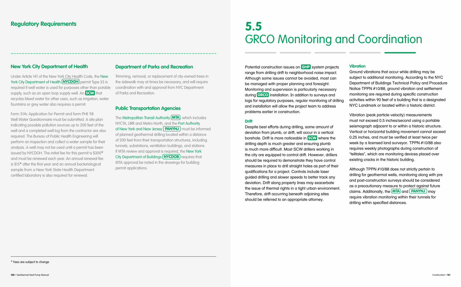
Construction / 131 130 / Geothermal Heat Pump Manual
Regulatory Requirements
New York City Department of Health
Under Article 141 of the New York City Health Code, the New York City Department of Health NYCDOH permit Type 33 is required if well water is used for purposes other than potable supply, such as an open loop supply well. An SCW that recycles bleed water for other uses, such as irrigation, water fountains or grey water also requires a permit.
Form 314c Application for Permit and form PHE 98 Well Water Questionnaire must be submitted. A site plan indicating possible pollution sources up to 200 feet of the well and a completed well log from the contractor are also required. The Bureau of Public Health Engineering will perform an inspection and collect a water sample for their analysis. A well may not be used until a permit has been issued by NYCDOH. The initial fee for this permit is $300* and must be renewed each year. An annual renewal fee is $15* after the first year and an annual bacteriological sample from a New York State Health Department certified laboratory is also required for renewal.
Department of Parks and Recreation
Trimming, removal, or replacement of city-owned trees in the sidewalk may at times be necessary, and will require coordination with and approval from NYC Department of Parks and Recreation.
Public Transportation Agencies
The Metropolitan Transit Authority MTA , which includes NYCTA, LIRR and Metro North, and the Port Authority of New York and New Jersey PANYNJ must be informed of planned geothermal drilling located within a distance of 200 feet from their transportation structures, including tunnels, substations, ventilation buildings, and stations. If MTA review and approval is required, the New York City Department of Buildings NYCDOB requires that MTA approval be noted in the drawings for building permit applications.
A.,(",0%5#+."),'/+,0."#0))/()#."# GHP #)&),($#*'.3(+,)#'%"2(#4'.$#1'0550"2#1'04,#,.#"(0278.'7..1#".0)(#0$*%+,9#B5,7./27#).$(#0))/()#+%"".,#8(#%6.01(1-#$.),#+%"##8(#$%"%2(1#;0,7#*'.*('#*5%""0"2#%"1#4.'()027,9#@."0,.'0"2#%"1#)/*('60)0."#0)#*%',0+/5%'5&#"(+())%'/'0"2#GRCO #0"),%55%,0."9#!"#%110,0."#,.#)/'6(&)#%"1##5.2)#4.'#'(2/5%,.'&#*/'*.)()-#'(2/5%'#$."0,.'0"2#.4#1'0550"2#%"1#0"),%55%,0."#;055#%55.;#,7(#*'.3(+,#,(%$#,.#%11'())#*'.85($)#(%'50('#0"#+."),'/+,0."9
Drift#J()*0,(#8(),#(44.',)#1/'0"2#1'0550"2-#).$(#%$./",#.4#1(60%,0."#4'.$#*5/$8-#.'#1'04,-#;055#.++/'#0"#%#6(',0+%5#8.'(7.5(9#J'04,#0)#$.'(#".,0+(%85(#0"# SCW #;7('(#,7(#1'0550"2#1(*,7#0)#$/+7#2'(%,('#%"1#(")/'0"2#*5/$8##
#,7(#+0,&#%'(#(=/0**(1#,.#+.",'.5#1'04,9#:.;(6('-#1'055(')#)7./51#8(#'(=/0'(1#,.#1($."),'%,(#,7(%6(#+.",'.5#$(%)/'()#0"#*5%+(#,.#1'055#),'%027,#7.5()#%)#*%',#.4#,7(0'#
#2/01(1#1'0550"2#%"1#)5.;('#)*((1)#,.#8(,,('#,'%+>#%"&#
#,7(#0))/(#.4#,7('$%5#'027,)#0"#%#,027,#/'8%"#("60'."$(",9#G7('(4.'(-#1'04,#.++/''0"2#8("(%,7#%13.0"0"2#)0,()##)7./51#8(#'(4(''(1#,.#%"#%**'.*'0%,(#%,,.'"(&9
Vibration#<'./"1#608'%,0.")#,7%,#.++/'#;705(#1'0550"2#$%(##)/83(+,#,.#%110,0."%5#$."0,.'0"29#B++.'10"2#,.#,7(#KL?#J(*%',$(",#.4#O/0510"2)#G(+7"0+%5#A.50+&#%"1#A'.+(1/'(#K.,0+(#GAAK#PQ -#2'./"1#608'%,0."#%"1#)(,,5($(",#
KL?#R%"1$%'>#.'#5.+%,(1#;0,70"#%#70),.'0+#10),'0+,9
S08'%,0."#T*(%>#*%',0+5(#6(5.+0,&U#$(%)/'($(",)##
)(0)$.2'%*7#%13%+(",#,.#.'#;0,70"#%#70),.'0+#),'/+,/'(9#
#
'(=/0'()#;((>5&#*7.,.2'%*7)#1/'0"2#+."),'/+,0."#.4#V,(55,%5()W-#;70+7#%'(#$."0,.'0"2#1(60+()#*5%+(1#.6('#
#1'0550"2#4.'#2(.,7('$%5#;(55)-#$."0,.'0"2#%5."2#;0,7#*'(##%"1#*.),F+."),'/+,0."#)/'6(&)#)7./51#8(#+.")01('(1##%)#%#*'(+%/,0."%'&#$(%)/'(#,.#*'.,(+,#%2%0"),#4/,/'(#+5%0$)9#B110,0."%55&-#,7(# MTA #%"1# PANYNJ #$%&##'(=/0'(#608'%,0."#$."0,.'0"2#;0,70"#,7(0'#,/""(5)#4.'##
5.5 GRCO Monitoring and Coordination
* Fees are subject to change

132 / Geothermal Heat Pump Manual Construction / 133
GRCO Monitoring and Coordination
GRCO #0"),%55%,0."#;055#'(=/0'(#%110,0."%5#+..'10"%,0."#,.#$0"0$0H(#4/',7('#10),/'8%"+()#1/'0"2#+."),'/+,0."#,.#%"#
8(#(6%5/%,(1#*'0.'#,.#,7(#),%',#.4#+."),'/+,0."#,.#(")/'(#,7%,#%"#%**'.*'0%,(#*5%"#.4#%+,0."#0)#0"#*5%+(9
All GHP Projects
Sidewalk drilling operations can obstruct building entrances and access to neighboring properties for a period of time. Alternate entrances and accessible routes may be required for the duration of construction.
Drilling operations can create wet and muddy site conditions. Methods to contain generated drilling fluids and ground water should be employed, such as lined dumpsters, hay bales and plastic or other liner material.
Drill rig masts may be as high as 35 feet, potentially requiring trimming, removal, and/or replacement of city-owned trees in the sidewalk or the project site.
The contractor should implement noise mitigation measures to the extent feasible to reduce the problem and comply with the city’s Noise Code, and Mechanical Code. 3
Closed Loop Systems
The loop field area will be disturbed by concentrated drilling activities and trenching, and must be restored after installation.
Construction duration may be long compared to an open loop or SCW project. However, using more than one rig can accelerate construction time.
Open Loop Systems
Well development and pumping tests involve pumping and discharging large volumes of ground water to the city sewer system for extended periods of time, from several days for well development to a continuous 72-hour aquifer pumping test. Plans for alternate discharge locations may sometimes be necessary.
Standing Column Wells
Auxiliary compressors and boosters may be required, and additional mitigation may be necessary to address increased drilling noise levels.
Ground water is blown to the surface from the well borehole during drilling, and at times cannot be effectively contained. Back up containment may be necessary.
Various monitoring activities in the neighborhood for vibrations, ground settlement and drift, may be highly visible and trigger neighborhood inquiries.
B+,060,0()#50),(1#8(5.;#%'(#'(+.$$("1(1#*'%+,0+()#4.'#GRCO #0"),%55%,0."#%"1#)7./51#8(#0"+.'*.'%,(1#0",.#,7(#+."),'/+,0."#)+7(1/5(9
All GHP Projects
Initiate discussions at least six months before drilling is scheduled to start with long lead-time agencies including NYCDOT for the RCA application, and MTA and PANYNJ on drilling approval requests.
A professional geologist/hydrogeologist or geotechnical engineer should be retained to document subsurface conditions, observe construction methods, and assist with addressing field modifications and contingency measures, if required.
#Closed Loop Systems
The loop piping construction should be inspected periodically by the geothermal engineer or a qualified project team member to ensure that the work complies with the construction documents and best industry practices, specifically borehole grouting, proper heat-fuse welding of pipe joints, flushing and air removal.
#Open Loop Systems
Conduct an aquifer pumping test to deter sustainable ground water yield.
Conduct borehole geophysical logging together with geologist’s drilling log and sieve analysis to determine location of well screen.
Before well construction, all drilling equipment and well construction materials should be thoroughly disinfected or shipped in a sealed, disinfected condition to prevent introducing bacteria into the well. All equipment and materials should also be disinfected prior to drilling additional wells to prevent cross contamination.
#Standing Column Wells
Conduct a pre-conditions survey of surrounding buildings and structures in the immediate vicinity of all wells, such as subway tunnels.
Upon drilling completion, a representative number of boreholes should be logged using a downhole video camera in addition to downhole geophysical logging, such as acoustic logs to establish baseline conditions. Videos and logs can therefore be used in the future for troubleshooting well performance.
Sustainable yield from the well may be significantly less than initial high yields observed during drilling, and should only be determined by conducting an aquifer pumping test.
Conduct a pumping test following well installation to verify the well yield relative to design bleed assumptions.
If ground water quality analysis was not previously performed, sample and analyze the first ground water encountered during drilling to verify selection of construction materials and whether or not a HX is necessary.
All drilling equipment and well construction materials should be thoroughly disinfected before introducing into the borehole.
5.6 GRCO Best Practices
3 Local Law 113 of 2005 amended New York City’s noise code to enforce limits on a variety of noise sources including construction.
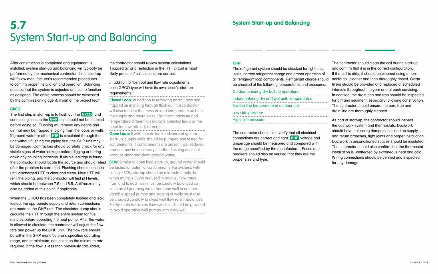
134 / Geothermal Heat Pump Manual Construction / 135
5.7 System Start-up and Balancing
B4,('#+."),'/+,0."#0)#+.$*5(,(1#%"1#(=/0*$(",#0)#0"),%55(1-#)&),($#),%',F/*#%"1#8%5%"+0"2#;055#,&*0+%55(#*('4.'$(1#8&#,7(#$(+7%"0+%5#+.",'%+,.'9#!"0,0%5#),%',F/*#;055#4.55.;#$%"/4%+,/'('E)#'(+.$$("1(1#*'.+(1/'()##
(")/'()#,7%,#,7(#)&),($#0)#%13/),(1#%"1#)(,#,.#4/"+,0."##%)#1()02"(19#G7(#(",0'(#*'.+())#)7./51#8(#;0,"())(1##8&#,7(#+.$$0))0."0"2#%2(",-#04#*%',#.4#,7(#*'.3(+,#,(%$9
GRCO#GRCO -#%"1#
+.""(+,0"2#50"()#,.#,7(# GHP #/"0,#)7./51#".,#8(#+./*5(1#8(4.'(#1.0"2#).9#N5/)70"2#;055#'($.6(#%"(8'0)#%"1##%0'#,7%,#$%(#,'%**(1#0"#*0*0"2#4'.$#,7(#5..*)#.'#;(55)9##!4#2'./"1#;%,('#.'#.,7('# HTF #0)#+0'+/5%,(1#,7'./27#,7(#
#8(#1%$%2(19#?.",'%+,.')#)7./51#+%'(4/55&#+7(+>#4.'#%"<)085(#)02")#.4#;%,('#5(%>%2(#8(4.'(#10220"2#.'#8.'0"2#1.;"#%"&#+./*50"2#5.+%,0.")9#!4#60)085(#5(%>%2(#0)#4./"1-#,7(#+.",'%+,.'#)7./51#5.+%,(#,7(#)./'+(#%"1#)7./51#'(,(),#%4,('#,7(#*'.85($#0)#+.''(+,(19#N5/)70"2#)7./51#+.",0"/(#/",05#10)+7%'2(1#:GN#0)#+5(%'#%"1#+5(%"9#K(;#:GN#;055#
%5).#8(#%11(1#%,#,70)#*.0",-#04#%**50+%85(9
,(),(1-#,7(#%**'.*'0%,(#)/**5&#%"1#'(,/'"#+.""(+,0.")#%'(#$%1(#,.#,7(#<:A#/"0,9#G7(#+0'+/5%,.'#*/$*#)7./51#
$0"/,()#8(4.'(#.*('%,0"2#,7(#7(%,#*/$*9#B4,('#,7(#;%,('#
#
'%"2(-#%"1#%,#$0"0$/$-#".,#5())#,7%"#,7(#$0"0$/$#'%,(#
,7(#+.",'%+,.'#)7./51#'(60(;#)&),($#+%5+/5%,0.")9#G'%**(1#%0'#.'#%#'(),'0+,0."#0"#,7(#:GN#+0'+/0,#0)#$.),#50>(5&#*'()(",#04#+%5+/5%,0.")#%'(#+.''(+,9
'(=/0'($(",)9
Closed Loop: In addition to removing particulates and trapped air in piping through flush out, the contractor will also monitor the pressure and temperature on both the supply and return sides. Significant pressure and temperature differentials indicate potential leaks or the need for flow rate adjustments.
Open Loop: If wells are drilled in advance of system start-up, supply wells should be pumped and tested for contaminants. If contaminants are present, well redevel-opment may be necessary if further flushing does not produce clear and clean ground water.
SCW: Similar to open loop start-up, ground water should be tested for potential contaminants. For systems with a single SCW, startup should be relatively simple, but when multiple SCWs are used in parallel, flow rates from and to each well must be carefully balanced so as to avoid pumping water from one well to another. Variable speed pumps and staging of wells must also be checked carefully to avoid well flow rate imbalances. Safety controls such as flow switches should be provided to avoid operating well pumps with a dry well.
GHP#G7(#'(4'02('%",#)&),($#)7./51#8(#+7(+>(1#4.'#,027,"())-#5(%>)-#+.''(+,#'(4'02('%",#+7%'2(#%"1#*'.*('#.*('%,0."#.4#%55#'(4'02('%",#5..*#+.$*."(",)9#C(4'02('%",#+7%'2(#)7./51#8(#+7(+>(1#%,#,7(#4.55.;0"2#,($*('%,/'()#%"1#*'())/'()X
Outdoor entering dry bulb temperature
Indoor entering dry and wet bulb temperatures
Suction line temperature at outdoor unit
Low side pressure
High side pressure
#G7(#+.",'%+,.'#)7./51#%5).#6('04&#,7%,#%55#(5(+,'0+%5#+.""(+,0.")#%'(#+.''(+,#%"1#,027,9# GHP #6.5,%2(#%"1#%$*('%2(#)7./51#8(#$(%)/'(1#%"1#+.$*%'(1#;0,7##
#*'.*('#)0H(#%"1#,&*(9#
System Start-up and Balancing
G7(#+.",'%+,.'#)7./51#+5(%"#,7(#+.05#1/'0"2#),%',F/*###
!4#,7(#+.05#0)#10',&-#0,#)7./51#8(#+5(%"(1#/)0"2#%#"."F#%+010+#+.05#+5(%"('#%"1#,7("#,7.'./275&#'0")(19#?5(%"#
0",('6%5)#,7'./27./,#,7(#&(%'#%"1#%,#(%+7#)('60+0"29##!"#%110,0."-#,7(#1'%0"#*%"#%"1#,'%*#)7./51#8(#0")*(+,(1#4.'#10',#%"1#)(10$(",-#()*(+0%55.55.;0"2#+."),'/+,0."9#G7(#+.",'%+,.'#)7./51#(")/'(#,7(#*%"-#,'%*#%"1##1'%0"#50"(#%'(#,7.'./275&#+5(%"(19
B)#*%',#.4#),%',F/*-#,7(#+.",'%+,.'#)7./51#0")*(+,##,7(#1/+,;.'>#)&),($#%"1#,7('$.),%,)9#J/+,;.'>##)7./51#7%6(#8%5%"+0"2#1%$*(')#0"),%55(1#."#)/**5&##%"1#'(,/'"#8'%"+7()-#,027,#3.0",)#%"1#*'.*('#0"),%55%,0."9#J/+,;.'>#0"#/"+."10,0."(1#)*%+()#)7./51#8(#0")/5%,(19#
#4.'#%"%$%2(9#

136 / Geothermal Heat Pump Manual Construction / 137
Commissioning# Cx #0)#%#)&),($%,0+#*'.+())-#$%"%2(1#8&#%#?.$$0))0."0"2#B/,7.'0,&# CxA -#,.#6('04&#,7%,#%#*'.3(+,##0)#1()02"(1-#+."),'/+,(1-#%"1#.*('%,(1#%)#0",("1(19#!,#0)##%#4.'$#.4#=/%50,&#+.",'.5#,.#(")/'(#4.'#,7(#.;"('-#%'+70,(+,-#1()02"#("20"(('-#+.",'%+,.')-#%"1#.*('%,0.")#),%44#,7%,#)&),($)#%"1#(=/0*$(",#4/"+,0."#+.''(+,5&#/*."#0"),%55%F,0."-#%"1#,7%,#,7(#*'.3(+,#0)#1.+/$(",(1#%"1#,/'"(1#.6('#
F,%,0.")-#4'.$#*5%""0"2#,.#%++(*,%"+(-#,7'./27#1()02"#
'(1/+(1#("('2&#/)%2(-#5.;('#.*('%,0"2#+.),)-#4(;('#+.",'%+,.'#+%558%+>)-#0$*'.6(1#8/0510"2#1.+/$(",%,0."-#%"1#0"+'(%)(1#.++/*%",#*'.1/+,060,&#%)#%#'()/5,#.4#%##8(,,('#;.'>*5%+(#("60'."$(",9
Geothermal Commissioning#Y"0=/(#,.# GHP #)&),($)#0)#%#,;.F+.$*."(",# Cx #'(60(;#*'.+())#.4#%8.6(#%"1#8(5.;#2'./"1#)&),($)9#G7(#)(5(+,F(1# CxA
GRCO #,&*(#*'.*.)(1#%)#;(55#%)#;0,7#%)).+0%,(1#%8.6(##
0"*/,#4'.$#.,7('#+.")/5,%",)#%)#%**'.*'0%,(-#0"+5/10"2#2(.5.20),)-#7&1'.5.20),)-#2(.,(+7"0+%5#("20"((')-##%"1#2(.,7('$%5#+.")/5,%",)9
*('4.'$(1#,7'./27./,#,7(#504(+&+5(#.4#%# GHP #*'.3(+,#,.#F
*%"&0"2#,%85(#%"1#,7(#'()*(+,06(#M&),($#J0%2'%$#4.'##
Closed Loop Well - illustration pg. 43, Figure 2.3.1
Open Loop Well - illustration pg. 49, Figure 2.3.5
Standing Column Well System - illustration pg. 55, Figure 2.3.8
#.'#%55#.4#,7()(#50),(1#,%)>)#.'#%$("1(1#;0,7#%110,0."%5#0,($)-#1(*("10"2#."#,7(#.;"('E)#"((1)9#!1(%55&-#<:A##
#
Routine Maintenance/Continuous Commissioning !"#%110,0."#,.#,7(#0"0,0%5# Cx #,%)>)#10)+/))(1#%8.6(-#0,#0)#
GHP #*'.3(+,#%"1#%1.*,(1#,.#6('04&#,7%,#*'.*('#*('4.'$%"+(#0)#$%0",%0"(19#O(5.;#%'(#).$(#0,($)#,.#+.")01('#;7("#1(6(5.*0"2#,70)#*'.2'%$X
5.8 Commissioning
All GHP Systems
Track and document the supply and return temperatures during various heating and cooling load conditions to verify system performance.
Check system performance in both heating and cooling seasons.
If a Building Management System (BMS) interface is available, set up trend logs in the BMS to perform this monitoring and reporting. Review information monthly at a minimum.
Closed Loop Systems
Regularly test loop piping.
Document system temperatures and pressures.
Perform water sampling of closed loop fluid yearly.
Open Loop Systems
Consider performing a yearly downhole camera survey of diffusion wells.
Record pressures, temperatures, and flow rates monthly at a minimum. If flow meters are not permanently installed, strap-on ultrasonic flow meters should be used.
Check well water system strainers regularly, preferably once a month, for excess debris. Consider using fine mesh strainers (30 mesh) for at least the first year of operation, especially if well water system heat exchangers include small tube devices which are subject to blockage.
Verify that balancing valves are properly set.
Perform ground water analysis. Compare to the levels deemed safe by manufacturers of the building system and equipment.
Standing Column Wells
Periodically inspect casing, Porter shroud, and pumps to insure proper well performance. Field inspections should also confirm that the pump setting is below the lowest water level during bleed conditions.
Verify balancing valves are properly set.
If variable speed pumps are used, measure and monitor flow rates at various pump speeds.
Compare ground water chemistry and elevation to the levels deemed safe by manufacturers of the building system and equipment.
Test bleed rate seasonally to establish the optimum and safe rate. Bleed cycles should also be documented.
Perform controls testing and demonstration, especially of safety controls to prevent well pumps from operating in dry conditions and freeze protection controls during heating. Well pump controls, variable speed drives, and staging must also be checked.
Commissioning

138 / Geothermal Heat Pump Manual Construction / 139
Witness Borehole Geophysical Logging
X
X X X X X X
X
X X X
X X X
X X X
X X X
X X
X X
X X
X X
X X
X
X
X
X X X
X X X
X X X
X X X
X X X
X X X
X X X
X X X
X X X
X X X
X X X
X X X
X X
X X
Verify Driller’s Equipment Has Been Disinfected Before Drilling
Review Sieve Analysis Confirm Well Screen Slot Size & Casing Selection
Review Water Sample Results Confirm Well Screen Slot Size & Casing Installation
Witness Aquifer Pumping Test (Drawdown Test) Witness Downhole Camera Survey
Review Tubing & Header Installation
Verify/Document Ground Water Elevations Review Additional Water Sample Analysis
Witness Tubing Pressure Testing
Review Historic Ground Water Levels for Areas Review Submersible Pump Installation
Witness Flushing of System Tubing
Review Potential Land Availability for Well System
Review Pump Installation
Review Project Goals (LEED Rating, Efficiency, etc.)
Review Heat Pump / Heat Exchanger Installation
Create or Review Owner’s Project Requirements and Basis of Design
Review All Primary & Secondary System Components
Design Review Maintenance Accessibility
Review All Piping Pressure Testing
Design Review Operation Requirements
Witness Flushing of System Piping
Design Review Training Requirements
Design Review Warranty Requirements
Design Review Replacement Parts Requirements
Add Cx Specifications to the Design Documents
Create a Cx Plan
Blank spaces = Not Applicable Blank spaces = Not Applicable
Below Ground Below Ground
Above Ground
Above GroundAbove & Below Ground
Commissioning Considerations Commissioning Considerations
Design P
hase
Constr
uctio
n
Ph
aseClos
ed Lo
op
Sy
stems
Closed
Loop
Sy
stems
Open Lo
op
Sy
stems
Open Lo
op
Sy
stems
Stand
ing
Colu
mn
Syste
ms
Stand
ing
Colu
mn
Syste
ms

140 / Geothermal Heat Pump Manual Construction / 141
Update Cx Plan when Contractors are onboard
Review Submittals
Conduct Installation Review
Prefunctional/Start-up Review
Perform Functional Testing
Record All System Flow Rates, Temperatures and Pressures
Performance Verification/Trending
Above & Below Ground
Review O&M Manuals
Review As-Built Documents
Review Training is Performed/Documented
Review Warranty Documents
Provide Final Report
Provide Systems Operations Manual
Conduct End of Warranty Review
Above & Below Ground
Commissioning Considerations Commissioning Considerations
Constr
uctio
n
Ph
aseAcce
ptance/
Tu
rnove
r
Closed
Loop
Sy
stems
Closed
Loop
Sy
stems
Open Lo
op
Sy
stems
Open Lo
op
Sy
stems
Stand
ing
Colu
mn
Syste
ms
Stand
ing
Colu
mn
Syste
ms
Blank spaces = Not Applicable Blank spaces = Not Applicable
X X X
X X X
X X X
X X X
X X X
X X X
X X X
X X X
X X X
X X X
X X X
X X X
X X X
X X X

142 / Geothermal Heat Pump Manual Operation and Maintenance / 143
Operation and Maintenance
66.0List of Abbreviations
GRCOGHP
HCI
IRBHX
SCW
Geothermal Heat Pump
Hydrochloric Acid
Iron-Related Bacteria
Standing Column Well
HDPE HVAC
Ground Coupling
High-Density Polyethylene
Heating, Ventilation, and Air Conditioning
Heat Exchanger
BMS
O&M
Building Management System
Operations and Maintenance

144 / Geothermal Heat Pump Manual Operation and Maintenance / 145
6.1 Operation and Maintenance
!"#$%%$&'()$#*+$,-'(*"#-".#/-("'$"-"&$# O&M #+,*0,-/#+,*)(.$1#-#&2$-,#+-'3#%*,#/-("'-("("0#*+'(/-2#+$,%*,/-"&$#
,-"0$#%,*/#1&3$.42$.#("1+$&'(*"1#-".#,*4'("$#&2$-"("0##'*#/-5*,#1$,)(&("0#-'#&,('(&-2#+*("'1#*%#*+$,-'(*"#-".#
#(1#"*'#541'#'3$#,$1+*"1(6(2('7#*%#64(2.("0#/-"-0$,1#*,#
8(/(2-,#'*#*'3$,# HVAC GHP ##
*&&-1(*"-2#("'$"1()$#1$,)(&("0#/-7#-21*#6$#"$&$11-,7#.$+$".("0#*"#'3$#GRCO
13*42.#-21*#6$#("&24.$.#'*#$"14,$#14&&$11%42#*+$,-'(*"#Figure 6.1 #(2241',-'$1#
Typical Operation & Maintenance AreasFigure 6.1
Diagram for GHP System Operation & MaintenanceFigure 6.1
Routine inspection of equipment and track status
Inspect and clean
Supplemental Heat Recovery Device
Monitor supply temperatures for supplemental heat recovery devices, if applicable
Monitor temperature and pressure of return
Investigate differences and imbalances between supply and return flows
To
Monitor and adjust supply air or water for occupant comfort
Isolation or control valve for shut-off
Monitor and clean strainers and filters
Confirm correct flow rate
regular filter changes
Return Air or Water from building spaces
Supply Airor Water to building spaces
Monitor temperature and pressure of supply
From
Geothermal Heat PumpGHP
GHP
Plate-Frame Heat Exchanger
Ground Coupling
Heat Transfer Fluid
HX
HX
HX
GRCO
GRCO GRCO
HTF
HTFHTF

146 / Geothermal Heat Pump Manual Operation and Maintenance / 147
GHP #171'$/#*+$,-'(*"#+,(/-,(27#(")*2)$1#&*"',*22("0##
-11$11#171'$/#*+$,-'(*"#'*#$"14,$#'3-'#+$,%*,/-"&$##building management system# BMS
#
9
##
#*,#$2(/("-'("0#/$-14,$/$"'#-".#&*"',*2#.$)(&$1##
#
All GHP Systems
Monitor pressure differential to confirm correct water flow to GHP .
#Closed Loop Systems
Monitor GRCO make-up water flow to confirm that leaks are not occurring in the loop field.
Identify increase in head loss in main supply and return headers, which may indicate restricted flow from GRCO.
Confirm balanced flow to and from individual loop circuits.
Monitor supply and return temperatures from GRCO to confirm expected thermal capacity is achieved.
Open Loop Systems
Monitor supply and return ground water temperatures to confirm thermal loss is within expected range.
Monitor supply and return ground water pressures to identify increase in head loss, which may indicate restricted flow.
Verify pumps are delivering required demand flow at time of measurement.
Check specific capacity for individual supply wells to confirm supply well screen slots are not clogged.
Check flow rates and pressure at diffusion wellheads to confirm diffusion well screen slots are not clogged.
Check amperage and voltage draw of submersible pumps for restrictions in piping or unusually high drawdown.
Monitor particulate load in “Y” strainer, heat pump strainers, and other filters, if used, to identify break in supply piping or well screens.
Identify changes in ground water quality and determine if potential for scaling, corrosion, or biofouling has increased.
If necessary, obtain coupons and monitor for potential corrosion of metallic components of system.
6.2 Operational Considerations
Standing Column Wells
Monitor supply and return ground water temperatures to confirm thermal loss is within expected range.
Monitor supply and return ground water pressures to identify increase in head loss, which may indicate restricted flow.
Check for unusually high drawdowns of ground water levels during bleed and non-bleed operation.
Confirm balanced supply and return flows in each well.
Monitor particulate load in “Y” strainer, heat pump strain-ers, and other filters as applicable to identify break in supply piping or well screens.
Identify changes in ground water quality and determine if potential for scaling, corrosion, or biofouling has increased.
If necessary, obtain coupons and monitor for potential corrosion of metallic components of system.
#
GHP #9
#
#
CxA #/-7#-21*###
:3$#/$&3-"(&-2#-".#0$*'3$,/-2#$"0("$$,1#13*42.#O&M #+,*&$.4,$1#+,(*,#'*#171'$/#1'-,'#4+#-".#
#
+,*+$,#171'$/#*+$,-'(*"#("#'3$#%4'4,$#-".#%*,#',*462$9GRCO #
HVAC #171'$/1#/-7#6$#-62$#'*#+,*/+'27#-..,$11#
#'*#0,$-'$,#/-("'$"-"&$#*,#$)$"#-6,4+'#171'$/#134'9#
Operational Considerations

148 / Geothermal Heat Pump Manual Operation and Maintenance / 149
#'3$# GHP #-".#'3$#GRCO
Figure 6.2 #
9"-"&$#13*42.#6$#("&24.$.#("#'3$#64(2.("0# HVAC #171'$/#
9
#
6.3 Maintenance
Closed Loop System !#&2*1$.#2**+#171'$/#$"'-(21#/("(/-2#/-("'$"-"&$##1("&$#'3$#GRCO #(1#1$2%9&*"'-("$.#-".#(1*2-'$.#%,*/##
HDPE #+(+("0#41$.#%*,#'3$###
#
##
:3$#64(2.("0#*+$,-'*,#13*42.#-21*#,$042-,27#("1+$&'###
#
Well Maintenance: Open Loop System Impulse Generation ToolFigure 6.2
Impulse generation creating nitrogen bubbles at well head

150 / Geothermal Heat Pump Manual Operation and Maintenance / 151
Open Loop Systems
("'$"1()$#*%#'3$#'3,$$#GRCO #'7+$1#6$&-41$#'3$7#-,$#O&M #
#
Submersible Pumps##
##
#
#
#
##
MaintenanceMaintenance
Well Screen Rehabilitation##
#
#
##
##
##
+-11$1#'3,*403#'3$# HVAC
##
##
iron-related bacteria# IRB #
##
#
#
#
HX #-".#0,*4".#
Rehabilitation Techniques##
Table 6.1
*"#'3$#&-1("0#*,#1&,$$"#-,$#'3$"#)(14-227#("1+$&'$.#'*#Figure 6.3 #
#
Figure 6.4 ##
#
#HCI #-,$#'3$#
#

Operation and Maintenance / 153 152 / Geothermal Heat Pump Manual
Well Rehabilitation Tools and TechniquesFigure 6.1
Tool o
r
Tec
hnique
Applicatio
n
1. Video well inspection
2. Wire brushing
3. Water jetting
4. Bailing
5. High-pressure segmental air lifting
6. Impulse Generation Tool
7. Hydrochloric Acid (HCl) treatment
8. Disinfection by chlorination
9. Surging
10. Pumping
Visually inspect well condition to identify type of problem (geochemical, biological or physical) and severity.
Physically loosen biological growth and mineral precipitation from the well casing and screen.
Use high-pressure water injection to loosen material on screen and gravel pack.
Manually remove loosened debris that falls to well bottom.
Inject air within screen zone to remove loosened debris and material from filter pack and surrounding area, and purge well.
‘Burst’ of nitrogen to loosen foreign matter from well screen and surrounding area.
Dissolve metal compounds encrusted on well screen, gravel pack and surrounding area.
Kills bacteria colonies in well, filter pack, and screen area.
Use plunger-type device to force acid and disinfectant into filter pack and surrounding area.
Pump well using submersible pump for additional removal of debris from filter pack and surrounding area. Can be used after procedures 2 through 5. Also used to remove residual acid and disinfectant after Procedures 7 and 8.
Downhole Video Inspection: Open Loop SystemFigure 6.3

154 / Geothermal Heat Pump Manual Operation and Maintenance / 155
Well Rehabilitation Tool: Wire BrushFigure 6.4 Maintenance
;/+421$#0$"$,-'(*"#'$&3"*2*07#(1#-"#(""*)-'()$###
DDC ##
#*4'#<64,1'1=#*%#&*/+,$11$.#"(',*0$"#0-1#'*#.(12*.0$#
Figure 6.5 #
Figure 6.6#
#'3$#)*24/$#*%#'3$#&3$/(&-2#.(1("%$&'-"'#41$.#"$$.1##
##
+$,/('# 1 #%,*/# NYCDEP ##
Figure 6.7 #+,*)(.$1###
1 For more information, see C 3 NYC Permits and Filings

156 / Geothermal Heat Pump Manual Operation and Maintenance / 157
Well Rehabilitation Tool: Impulse Generation Ground Water Pumped During Impulse GenerationFigure 6.5 Figure 6.6
Hydropuls® tool
Technician lowering tool into well
Biofilm and precipitated iron pumped from well
Clear ground water after impulse generation

158 / Geothermal Heat Pump Manual Operation and Maintenance / 159
Images from Downhole Well InspectionFigure 6.7
Top: Well screen before rehabilitation
Bottom: Well screen after rehabilitation
Maintenance
Standing Column Well System##
SCW
HX #
-21*#141&$+'(62$#'*#+4/+#/*'*,#64,"*4'#(%#'3$#,$'4,"##
#
####
##
#

160 / Geothermal Heat Pump Manual Case Studies / 161
Case Studies
7Case Studies
!"#$%&#'()*#+,-./"#0),12).#320,-24#3(5"-)63-,(5#0)(7%3-#12528%)9#-:%#;%02)-1%5-#(<#;%",85#25=#+(5"-)63-,(5#DDC #2=1,5,"-%)"#2#=,>%)"%#"3(0%#(<#&()*#,5#>2),(6"#?6,4=,58#-.0%"#25=#",@%"A#B5#)%3%5-#.%2)"9#;;+#:2"#%53(6)28%=#-:%#,104%1%5-2-,(5#(<# GHP #"."-%1"#-(#2==)%""#"023%#3(5=,-,(5,58#=%125="#&:,4%#)%=63,58#%5%)8.#3(5"610-,(5A#!"#2#)%"64-9#;;+#:2"#23C6,)%=#
(0%)2-,58#DEF#"."-%1"A#G:%#<(44(&,58#2)%#5(-2?4%#0)(7%3-"#-:2-#0)(>,=%#3(5",=%)2?4%#,5",8:-#(5#-:%#6"%##(<#8%(-:%)124#&,-:,5#-:%#+,-.A#
1. Brooklyn Children’s Museum Open Loop System
2. Queens Botanical Garden Open Loop System
3. Weeksville Heritage Center Closed Loop System
4. Lion House at the Bronx Zoo Standing Column Well System
5. Staten Island Museum at Snug Harbor Closed Loop System
Long Isl
and Sound
Huds
on R
iver
Atlantic Ocean
Bronx
Brooklyn
Queens
Manhattan
Staten Island
1 3
5
2
4

162 / Geothermal Heat Pump Manual Case Studies / 163
Brooklyn Children’s MuseumOpen Loop System
Total Building Area: 55,000 sq. ft. (new addition only) Building Loads: 2,661,000 Btu/h for heating, 275 tons for cooling Number of Wells: 2 supply, 2 diffusion Number of Heat Pumps: 23 units LEED Certification: Gold
H),8,5244.#%"-2?4,":%=#,5#IJKK#,5#L)(&%)#F2)*9#-:%#16"%61#,"#36))%5-4.#",-62-%=#,5#-:%#+)(&5#E%,8:-"#"%3-,(5#(<#L)((*4.5A#!#5%&#MM9NNN#"CA#<-A#2==,-,(5#(0%5%=#,5##ONNJ#25=#=(6?4%=#-:%#-(-24#?6,4=,58#",@%#-(#IIN9NNN#"CA#<-A#G:%#5%"%61#,53()0()2-%=#125.#"6"-2,52?4%#=%",85#<%2-6)%"#25=#23:,%>%=#2# LEED-:%# USGBC A#!"#02)-#(<#-:%#(>%)244#%5%)8.#6"%#)%=63-,(59#2# GHP #"."-%1#&2"#,5"-244%=9#&:,3:#24"(#2>(,=%=#-:%#6"%#(<#65",8:-4.#3((4,58#-(&%)"#(5#-:%#)((<-(09#%4,1,52-%=#
G:%#16"%61/"#=%",85#-%21#3:("%#25#(0%5#4((0#"."-%1#&,-:#-&(#"6004.#25=#-&(#=,<<6",(5#&%44"9#%23:#2-#2#=%0-:##(<#PQM#<%%-#,5-(#-:%#R21%3(#2C6,<%)# 1 A#G&(#"6004.#&%44"9#
#&%)%#5%3%""2).#-(#1%%-#-:%#16"%61/"#0%2*#4(2=A#S23:#
#
&)200%=9#"3:%=64%#JN#"-2,54%""#"-%%4A#T3)%%5#4%58-:"#<()#-:%#"6004.#25=#=,<<6",(5#&%44"#2)%#INN#<%%-#25=#ONN#<%%-9#)%"0%3-,>%4.9#25=#%23:#=%",85%=#&,-:#2#"4(-#",@%#(<#NANQNA#
12-%#-(-24#32023,-.#(<#PMN#-(5"A
;),44,58#3(5=,-,(5"#2-#-:,"#",-%#&%)%#0)(?4%12-,3#?%326"%##(<#561%)(6"#?(64=%)"#%53(65-%)%=A#G:%#16"%61#,"#4(32-%=#5%2)#-:%#-%)1,524#1()2,5%9#&:,3:#3(5","-"#(<#
-:%#42"-#8423,24#0%),(=#(>%)#IN9NNN#.%2)"#28(A#L(64=%)"#325#"4(&#=),44,58#-,1%#25=#,53)%2"%#3("-"A#;6),58#-:,"#0)(7%3-9#-:%#=),44%)"#%,-:%)#=),44%=#-:)(68:#-:%#?(64=%)"##
Brooklyn Children’s Museum
1a Supply Wells 1b
2a Diffusion Wells 2b
!4-:(68:#-:%#?6,4=,58#&2"#"6?"-25-,244.#3(104%-%=#,5##-:%#<244#(<#ONNU9#0)(?4%1"#=%>%4(0%=#":()-4.#=6),58#
#IRB #25=#1,5%)24#
#
-:%#=,<<6",(5#&%44#"3)%%5"#25=#)%"-),3-#&2-%)#)%-6)5,58#-(#-:%#2C6,<%)A#B)(5#?23-%),2#2)%#52-6)244.#0)%"%5-#,5#8)(65=#&2-%)9#25=#325#0)(4,<%)2-%#,<#-:%#&2-%)#,"#24"(#52-6)244.##:,8:#,5#=,""(4>%=#,)(59#&:,3:#23-"#2"#2#<((=#"6004.#<()##-:%#?23-%),2A#!%)2-,58#-:%#&2-%)#25=#,53)%2",58#-:%#-%10%)2-6)%#2"#,-#)65"#-:)(68:#-:%# HVAC #"."-%1##
+:4(),52-,(5#(<#%23:#&%44#,"#8%5%)244.#-:%#-)%2-1%5-#(<#3:(,3%9#?6-#=(%"#5(-#36)%#-:%#0)(?4%1A#V()%(>%)9#0%)1,--,58#?.#-:%# NYSDEC #=,=#5(-#244(:%1,324#-)%2-1%5-#?%326"%#(<#0(-%5-,24#8)(65=#&2-%)#3(5-21,52-,(5A#
%23:#&%44#6",58#>2),(6"#,5=6"-).#1%-:(="#&2"#5%3%""2).#-(#)%"-()%#-:%#"."-%1#0%)<()1253%#-(#-:%#(),8,524#=%",85A#
?%,58#,5>%"-,82-%=#?.#;;+#-(#12,5-2,5#-:%#,5-%8),-.#(<#-:%#
%5-4.#&()*,58#2"#(),8,5244.#=%",85%=9#25=#0%),(=,3#=(&5
Challenges:
Ground water contains moderate to high amounts of iron and other dissolved minerals and inorganics, which can precipitate onto well screens, piping and valves.
Ground water contains moderate amounts of IRB , which can clog well screens with biofilm-type deposits if not properly treated.
Wells remained idle for extended periods of time after construction, which may have contributed to ‘silting in’ of wells and IRB growth on the well screens.
NYSDEC permit did not allow use of chemical treatment or introduction of disinfectant to the aquifer.
Subsurface beneath the site contains numerous glacial boulders, making drilling difficult.
Use of mud rotary drilling method may have imbedded drilling mud into the well screen area and filter pack, which can be extremely hard to remove and may impede the flow of water back to the aquifer.
1a
1b
2a 2b
N
1 For more information on aquifers, see Chapter 3

164 / Geothermal Heat Pump Manual Case Studies / 165
Queens Botanical GardenOpen Loop System
Total Building Area: 16,000 sq. ft. Building Loads: 378,100 Btu/h for heating, 37 tons for cooling Number of Wells: 1 Supply, 2 Diffusion Number of Heat Pumps: 8 units LEED Certification: Platinum
The Queens Botanical Garden is located in Flushing, Queens. The Garden, which is open to the public, is situated on 39 acres of diverse garden landscapes in an ethnically diverse neighborhood. It originally started as part of the 1939 New York World’s Fair and eventually expanded into Flushing Meadows-Corona Park. During construction for the 1964 World’s Fair,the Garden was relocated to its current location across the street from Flushing Meadows-Corona Park. Because of the Garden’s environmental stewardship and multicultural diversity, it decided to undertake an ambitious sustain-able agenda for its new administration building and visitor’s center. At the completion of the project in 2007, the building was awarded the LEED -tion, the highest award for a ‘green’ building, and also
A GHP system was considered to help reduce energy consumption for heating and cooling, and an open loop system was selected and incorporated into the building design. The two-story structure provides approximately
spaces. Based on the building’s cooling load of 37 tons and 378,100 Btu/h for heating, one supply well and two diffusion wells were installed. Each of the three wells was drilled and completed at 305 feet below grade using black pipe steel for casing, and 120 feet of schedule 80 stainless steel screen at the bottom. Eight individual heat pumps are used to provide 10 tons per unit, how-ever only 4 or 5 of the units are used at any one time, depending on demand. The maximum pumping rate for the supply well was designed for 160 gpm.
Queens Botanical Garden Administration Building
Final depth of the well and screen placement was determined by interpreting the geophysical log of a test well in addition to correlating the driller’s logs and sieve
viability of the test well, it was later converted to a supply well. Well completion reports from an old, existing onsite irrigation well were also reviewed to corroborate subsur-face information for the GHP system.
Soon after system startup, at least one of the diffusion wells developed higher than normal back pressure and
of each diffusion well indicated that a thorough redevel-opment of the wells was necessary. Both traditional and newer, innovative technologies were used for the
lowered into each well with a drill rig to ‘scrub’ and physically dislodge any encrusted, solid material on the interior wall of each well. An impulse generation tool was then lowered near the well screen, which sent out a ‘burst’ of compressed nitrogen gas, approximately 100 feet radially to dislodge any foreign matter such as
pumped out of each well containing the loosened waste material and properly disposed. Pulsing and pumping within each well continued until ground water was determined to be free and clear of any turbidity.
After well redevelopment, an in-line ultra-violet (UV)
water entered the building to disinfect the IRB that caused the biofouling. Other new technologies, which require no energy source or maintenance, are also currently being tested for long term use. An additional well in the near future is planned to supplement the existing system.
Challenges:
Deposits within the aquifer contained large amounts of clay that may have reduced permeability.
Ground water contained moderate amounts of dissolved iron that can precipitate onto piping and valves.
Ground water contained moderate amounts of IRB , which can clog well screens with biofilm-type deposits.
Botanical Garden facility is in a high water table area.
Wells were completed prior to building construction and remained idle for long periods of time, which may have contributed to IRB growth.
NYSDEC permit did not allow the use of chemical treatment of wells or introduction of disinfectant to the aquifer.
Site geology is complex and glacially altered, therefore determining which aquifer the wells were screened in was difficult. NYSDEC does not allow the use of the deeper Lloyd aquifer to be used for non-potable supply.
Use of mud rotary drilling method can imbed drilling mud into the well screen and surrounding gravel pack, which is extremely hard to remove and impedes the flow of water back to the aquifer.

166 / Geothermal Heat Pump Manual Case Studies / 167
Weeksville Heritage Center Closed Loop System
Total Building Area: 16,400 sq. ft. Building Loads: 108 tons for cooling Number of Boreholes: 48 closed loop boreholes Number of Heat Pumps: 10 units LEED Certification: Gold (anticipated)
Weeksville Heritage Center Site during loop drilling
=%=,32-%=#-(#-:%#!<),325#!1%),325#3(1165,-.#&:(#4,>%=##,5#-:,"#L)((*4.5#5%,8:?():((=#(>%)#(5%#:65=)%=#.%2)"#28(A#G:%#3%5-%)#&,44#"600()-#-:%#Y%%*">,44%#T(3,%-.#25=#
2=723%5-#-(#-:%#5%&#?6,4=,58A#G:%#?6,4=,58#,"#36))%5-4.#
ONIOA#$61%)(6"#"6"-2,52?4%#<%2-6)%"#&%)%#,5346=%=#,5#-:%#=%",859#25=#-:%#0)(7%3-#,"#25-,3,02-%=#-(#23:,%>%##LEED #D(4=#&:%5#3(104%-%=A
G:%#T(3,%-.#=%3,=%=#-(#6"%#2# GHP #"."-%1#<()#"023%#3(5=,-,(5,58#25=#-(#)%=63%#-:%#?6,4=,58/"#%5%)8.#3(5"610-,(5A#G:%#3%5-%)/"#",-%#:2"#",1,42)#8)(65=#&2-%)#3(5=,-,(5"#2"#-:%#L)((*4.5#+:,4=)%5/"#V6"%619#25=#
&2"#(),8,5244.#3:("%5#<()#-:%#",-%A#;;+#,5,-,244.#=),44%=#-:)%%#-%"-#&%44"#25=#0%)<()1%=#?()%:(4%#8%(0:.",324#4(88,58#=(&5#-(#OUN#<%%-#2"#&%44#2"#3(5=63-,58#25#2C6,<%)#0610,58#-%"-A#+(106-%)#1(=%4,58#(<#-:%#0610,58##"3%52),(#&2"#24"(#0%)<()1%=#-(#=%-%)1,5%#-:%#2C6,<%)/"#:.=)264,3#0)(0%)-,%"#25=#,-"#"6"-2,52?,4,-.A#!#-:()(68:#
#?%#2?4%#-(#0)(>,=%#-:%#32023,-.#(<#8)(65=#&2-%)##5%3%""2).#<()#25#(0%5#4((0#"."-%1A
E(&%>%)9#2<-%)#32)%<64#%>2462-,(5#(<#-:%#&2-%)#C624,-.9##-:%#2524.","#":(&%=#-:2-#%4%>2-%=#,)(5#4%>%4"#1,8:-#3(5-)2,5=,32-%#-:%#6"%#(<#25#(0%5#4((0#"."-%1#?%326"%#3:%1,324#-)%2-1%5-#1,8:-#24"(#?%#)%C6,)%=A#G:%#0(-%5-,24#<()# IRB #0)(4,<%)2-,(5#25=#?,(<(64,58#(<#&%44#"3)%%5"##&2"#2#"%),(6"#3(53%)5#<()#<6-6)%#(0%)2-,(5#25=#"."-%1##4(58%>,-.A#G:%#0)(7%3-#-%21#42-%)#)%>,",-%=#-:%#(-:%)#GRCO #"."-%1#&(64=#24"(#?%#"6,-2?4%#<()#-:%#0)(7%3-#25=#0)(>,=%#
G:%#21(65-#(<#(0%5#425=#(5#-:%#0)(7%3-#",-%#&2"#-:%#=%-%)1,5,58#<23-()#-:2-#244(&%=#-:%#=%",85#-%21#-(#06)"6%#2#34("%=#4((0#"."-%1A#L%326"%#-:%#5%&#?6,4=,58#(54.#
2)%2#&2"#2>2,42?4%#-(#0)(0%)4.#233(11(=2-%#2#34("%=#4((0#"."-%1A#G:%# HVAC #"."-%1#64-,12-%4.#)%C6,)%=#QJ#34("%=#4((0#?()%:(4%"9#ON#<%%-#202)-#&,-:#2#=%0-:#(<##
]((0"#2)%#8)(60%=#,5-(#<(6)#0%)#3,)36,-9#)(6-%=#-(#2#3%5-)24#125,<(4=#>264-9#25=#-:%5#0,0%=#-(#-:%#?6,4=,58/"#1%3:25,324#)((1A#L6,4=,58#%C6,01%5-#3(5","-"#(<#-%5#DEF"#-:2-#0)(>,=%#2#-(-24#(<#INJ#-(5"#(<#0%2*#3((4,58A
4((0#3,)36,-"#2)%#34("%4.#3(()=,52-%=#&,-:#65=%)8)(65=#"-()1&2-%)#4,5%"#25=#(-:%)#2006)-%5253%"#-(#2>(,=#,5"-2442-,(5#25=#(0%)2-,(5#0)(?4%1"A#
Challenges:
Decision of using an open loop system with potential for IRB issues or switching to less efficient and costlier closed loop system.
Ground water contained moderate amounts of dissolved iron, that may precipitate onto well screens, piping and valves of an open loop system.
Boulders deposited by the terminal moraine at times slowed the drilling of wells and boreholes.
Coordinating drilling of 48 closely-spaced loop boreholes and connector piping with other site features, including the stormwater management system that uses under-ground drainage piping, drywells, a constructed wetland, filtering soils and liners.
Coordinating loop field installation after removal of contaminated urban fill.

168 / Geothermal Heat Pump Manual Case Studies / 169
Lion House at the Bronx Zoo Standing Column Well System
Lion House
SCW Standing Column Wells
#$'+#E,"-(),3#]25=12)*9#25=#36))%5-4.#:(6"%"#-:%#
#25=#0425-#4,<%#<)(1#-:2-#)%8,(5#(<#-:%#&()4=A#G:%#)%5(>2-%=#?6,4=,58#&2"#3(104%-%=#,5#ONNZ#25=#23:,%>%=# LEED ##
#&%44#"."-%1#&2"#,5"-244%=#-(#%4,1,52-%#-:%#5%%=#<()#3((4,58#-(&%)"9#"6004%1%5-,58#25#(5",-%#<6%4#3%449#2#3(8%5%)2-,(5#0425-#25=#2#3(5=%5"2-%#&2"-%#:%2-#)%3(>%).#"."-%1A
:%2-,58#25=#3((4,58#<()#-:%#QN9NNN#"CA#<((-#?6,4=,58A##S23:#:%2-#0610#0)(>,=%"#PN#-(5"#(<#3((4,58#25=#PNN9NNN#L-6\:#(<#:%2-,589#&,-:#2#"(6)3%#&2-%)#-%10%)2-6)%#(<#JN#°X##<()#3((4,58#25=#QM#° #=%",85#)2-%#,"#MQQ#8019#()#INJ#801#0%)#&%44A
X,>%#"-25=,58#3(4615#&%44"#2-#I9MNN#<%%-#=%%0#&%)%##=),44%=#,5-(#3(10%-%5-#?%=)(3*#*5(&5#2"#-:%#E2)-425=#X()12-,(5# 2 9#&:,3:#,"#-:%#0),53,024#?%=)(3*#65,-#<(65=##2-#-:%#",-%#25=#,"#3(10),"%=#(<#3)."-244,5%#1,32#"3:,"-A#
##
2)%2A#B5-%)3%0-,58#127()#<264-"#()#<)23-6)%"#&(64=#:2>%#
<)23-6)%=#?%=)(3*#2C6,<%)A#L.#"%5=,58#"%,"1,3#",8524"#=%%0#,5-(#-:%#8)(65=#6",58#2#"."-%12-,3#200)(23:9#,5=,>,=624#?%=)(3*#65,-"#&%)%#=,<<%)%5-,2-%=#?.#-:%##
#-(#-:%#"6)<23%A#G:%#8%(0:.",324#,5>%"-,82-,(5#&2"##3(5=63-%=#2<-%)#:(6)"#,5#-:%#%>%5,58#-(#2>(,=##=,"-6)?,58#25.#(<#-:%#@((#25,124"A
#"(6-:#4,5%#(5#-:%#&%"-#",=%#(<#-:%#],(5#E(6"%#25=##
#)65#0%)0%5=,3642)#-(#-:,"#4,5%#24(58#-:%#"(6-:#",=%##
##
-:%)%#&%)%#"6?"-25-,24#<)23-6)%=#()#<264-#@(5%"#?%5%2-:#-:%#2)%2A#+())%42-,(5"#-(#<264-#@(5%"#200%2)%=#2-#25#2>%)28%#=%0-:#(<#UNN#<%%-#?%4()2=%#25=#2"#=%%0##2"#I9NNN#<%%-A#!#-%"-#&%44#&2"#=),44%=#-(#I9PNN#<%%-#25=#
3(4615#&%449#?6-#5(-#<()#25#(0%5#4((0#"."-%1A#G:%#2>%)28%#8)(65=#&2-%)#.,%4=#<()#-:,"#-.0%#(<#<()12-,(5##,"#QN#801#&,-:#25#2>%)28%#-%10%)2-6)%#(<#MM#°XA
!524.","#(<#-:%#?()%:(4%#8%(0:.",324#4(8"#24"(##,5=,32-%=#-:2-#-:%#?%=)(3*#&2"#3(10%-%5-9#25=#&(64=##
#MN#<%%-#,5-(#3(10%-%5-#?%=)(3*#2"#0%)#$%&#'()*##T-2-%#)%8642-,(5"A
Total Building Area: 40,000 sq. ft. Building Loads: 1,057,000 Btu/h for heating, 56 tons for cooling Number of Wells: 5 Standing Column Wells Number of Heat Pumps: 6 units LEED Certification: Gold
Challenges:
Pieces of bedrock within the borehole can dislodge and fall into the well, creating system problems.
Balancing the supply and return flows to multiple wells interconnected by a manifold with a varying yield can be problematic.
SCW
SCW
SCW
SCW
SCW
N
2 For more information on bedrock formations, see Chapter 3
Performing aquifer pumping tests of individual and multiple wells pumping together to evaluate the aquifer’s hydraulic response during system operation is critical.
Determination of a seismic fault zone under site to locate water-bearing fractures.

170 / Geothermal Heat Pump Manual Case Studies / 171
Staten Island Museum at Snug Harbor Closed Loop System
Total Building Area: 16,800 sq. ft. Building Loads: 1,114,400 Btu/h for heating,91.5 tons for cooling Number of Boreholes: 32 boreholes, 500 ft. deep Number of Heat Pumps: 5 units LEED Certification: Silver (Anticipated)
#,5-(#2#5%(32-,(5#2-#-:%#T568#E2)?()#+64-6)24#+%5-%)#
#T-2-%5#B"425=/"#5()-:#":()%4,5%A#G:%#16"%61#&,44#?%#:(6"%=#,5#-:%#5%&4.#)%5(>2-%=#L6,4=,58# A 9#&:,3:#,"#
G:%#16"%61#)%5(>2-,(5#,"#24"(#25-,3,02-%=#-(#23:,%>%##2# LEED
Y,-:#,-"#=,>%)"%#3(44%3-,(5"#25=#2)3:,>%"9#-:%#16"%61##&,44#5%%=#-(#?%#-%10%)2-6)%#25=#:61,=,-.#3(5-)(44%=A#E%2-,58#25=#3((4,58#4(2="#&%)%#%"-,12-%=#-(#?%#I9IIQ9QNN#
)((<A#!# GHP #"."-%1#244(&%=#-:%#:,"-(),3#%5>%4(0%#-(#)%12,5#,5-23-#25=#&(64=#5(-#3)%2-%#2#>,"624#(?"-)63-,(5#
5%2)?.#-(#"%)>%#-:%#?6,4=,58A#
B5,-,244.9#$'+# DDC #=),44%=#(5%#-%"-#?()%:(4%#=(&5##-(#2#=%0-:#(<#JUN#<%%-#-(#%>2462-%#-:%#<%2",?,4,-.#(<#2##"-25=,58#3(4615#&%44#"."-%1A#!<-%)#=),44,58#-(#IMN#<%%-9#65<)23-6)%=#-(#1(=%)2-%4.#<)23-6)%=#?%=)(3*#&2"#%53(65-%)%=9#0),12),4.#3(10("%=#(<#"%)0%5-,5,-%#25=#"3:,"-A#L2"%=#(5#"%)0%5-,5,-%#"2104%"#%4"%&:%)%#,5##-:%#3,-.9#-:%)%#&2"#2#:,8:#0)(?2?,4,-.#-:2-#-:,"#)(3*#-.0%#&(64=#3(5-2,5#3:)."(-,4%9#25#2"?%"-("#3(5-2,5,58##1,5%)249#25=#1,8:-#-),88%)#2==,-,(524#%5>,)(51%5-24#3(53%)5"A#E(&%>%)9#2524.","#(<#=),44#36--,58"#<()##2"?%"-("#3(5-2,5,58#1,5%)24"#&2"#5%82-,>%A
!4"(9#2<-%)#3(5=63-,58#2#0610,58#-%"-#(5#-:%#?()%:(4%9###
.,%4=#0("",?4%#&2"#(54.#Z#8019#&:,3:#=,=#5(-#1%%-#-:%#1,5,161#)%C6,)%1%5-"#<()#2#"6"-2,52?4%#T+YA#+(1?,5%=#
#4(&#.,%4=#",8524%=#-:2-#2#T+Y#()#25#(0%5#4((0#"."-%1#
"."-%1#200%2)%=#-(#?%#-:%#?%"-#(0-,(5#<()#-:,"#0)(7%3-A#G:%#<23,4,-.#:2=#-:%#5%3%""2).#2>2,42?4%#(6-=(()#"023%##
5%5-"9#25=#&(64=#?%#,"(42-%=#<)(1#-:%#65<2>()2?4%#"6?"6)<23%#3(5=,-,(5"A
G&(#?(),58"#<()#-%"-#4((0"#&%)%#3(104%-%=#-(#>%),<.#8%(4(8,3#3(5=,-,(5"#,5#"%02)2-%#3()5%)"#(<#-:%#0)(0("%=#
25=#=,<<6",>,-.A#D)(65=#&2-%)#-%10%)2-6)%#&2"#=%-%)1,5%=#-(#?%#?%-&%%5#MZ#25=#ZI#=%8)%%"#X2:)%5:%,-A#!4-:(68:#5(-#=%0%5=%5-#(5#8)(65=#&2-%)#-%10%)2-6)%9#-:%#&2-%)#325#,53)%2"%#-:%)124#3(5=63-,>,-.#25=#,10)(>%#-:%#
#B5#-:,"#32"%9#4(&%)#8)(65=#&2-%)#-%10%)2-6)%"#&(64=##
=6),58#3((4,58#2004,32-,(5"A
-:%#)%C6,)%=#PO#?()%:(4%"9#%23:#2-#2#=%0-:#(<#MNN#<%%-A#G:%#4((0"#2)%#3(10),"%=#(<#2#5(1,524#IAOM#,53:# HDPE #
#2)%#-,%=#,5-(#(5%#3,)36,-#25=#%23:#3,)36,-#,"#)(6-%=#-(##-:%#125,<(4=9#2#?6),%=#>264-#4(32-%=#,5#-:%#3%5-%)#(<#-:%#
#G:%#125,<(4=#&,44#?%#3(55%3-%=#-(#-:%#?6,4=,58/"##
#"6004.#25=#)%-6)5#:%2=%)"A
G:%#34("%=#4((0#"."-%1#,"#%""%5-,244.#12,5-%5253%##<)%%#25=#=(%"#5(-#)%C6,)%#25.#"0%3,24#":2<-"#()#(0%5,58"#
#<644.#)%"-()%=#-(#,-"#(),8,524#6"%#2"#25#(0%5#425="320%=#
Snug Harbor Cultural Center
A Staten Island Museum, Building A
1 Loop Field
1
N
A
Challenges:
Making decision to switch from standing column well to less efficient and costlier closed loop system
Locating loop field in area with mature trees that neces-sitated removal or relocation by the Parks Department
Adjusting field size and borehole spacing to accommo-date the building’s strong cooling dominant profile, and avoid long-term thermal build-up in the ground.

1 2 See Section 3.2 and Figure 3.3
Appendix A / 173 0172 / Geothermal Heat Pump Manual
Appendix A
AA 1 Hydrogeology and its Limiting Factors on GHP Systems
A.1 Consolidated Bedrock
!"#$%&'()$*+$,(-#&./*($01$2"&##$3&*4/&1$&'56$213#+7$8"*5"$9&'4$'.-#+2$2'$1',(:#+2$/&#;$2"#$<'&-"/4$=(#*++7$>(8''-$?/&0.#7$/(-$?/("/22/($@5"*+2A$B55'&-*(:$2'$%,..#2*($=CDEF7$3,0.*+"#-$01$G#&.4,22#&$/(-$B&('87$HIJE7$2"#$>(8''-$?/&0.#$*+$2"#$4'+2$3&'-,52*K#$+',&5#$'9$:&',(-$8/2#&$/4'(:$2"#$3&#DL/40&*/(7$L/40&*/(DM&-'K*5*/($&'56+$*($2"#$%&'()A$!"#1$213*5/..1$1*#.-$NJ$:34$/(-$&/(:#$9&'4$H$2'$EOO$:34A$C/2#&$P,/.*21$*+$:#(#&/..1$/55#32/0.#$9&'4$2"*+$9'&4/2*'(7$"'8#K#&7$"/&-(#++$/(-$/.6/.*(*21$*++,#+$4/1$0#$/$3&'0.#4$*($+'4#$.'5/2*'(+$9'&$=QG$#P,*34#(2A
!"#$?/("/22/($@5"*+27$/$"/&-$:&##($2'$0./567$4*5/5#',+$&'56$*+$:#(#&/..1$.#++$3&'-,52*K#$2"/($2"#$>(8''-$4/&0.#A$R*++'.K#-$*&'($*($2"#$+5"*+2$*+$5'44'($8"*5"$5/($*($#)5#++*K#$/4',(2+$5&#/2#$3&'0.#4+$9'&$8#..$3,43+$/(-$+5&##(+7$"'8#K#&$/.6/.*(*21$/(-$"/&-(#++$/&#$.'8#&$2"/($*($2"#$4/&0.#A$?'+2$3&'-,52*K#$+,33.*#+$'9$:&',(-$8/2#&$/&#$9',(-$/2$-#32"+$.#++$2"/($EOO$9##2A$R&*..*(:$-##3#&$9'&$8/2#&$*+$3'++*0.#7$"'8#K#&7$/..$8/2#&$*($0#-&'56$*+$"#.-$*($2"#$*(2#&5'((#52#-$9&/52,&#+$8"*5"$:#(#&/..1
-#5&#/+#$*($+*S#$8*2"$-#32"A$R#32"$2'$0#-&'56 $ 1 $K/&*#+$
&'56$8/..$#)3'+,&#+$/2$2"#$+,&9/5#$*($('&2"#&($?/("/22/($/(-$%&'()$2'$'K#&$H7OOO$9##2$0#.'8$2"#$+,&9/5#$*($+',2"#&($T,##(+A
>($:#(#&/.7$4'+2$'9$2"#$0#-&'56$0#(#/2"$2"#$L*21$*+$$"/&-7$5'43#2#(2$4/2#&*/.$2"/2$5/($#/+*.1$0#$-&*..#-$9'&$$/$:#'2"#&4/.$.''3$'&$8#..A$Q'8#K#&7$5#&2/*($9'&4/2*'(+$+,5"$/+$2"#$>(8''-$?/&0.#7$<'&-"/4$=(#*++7$/(-$@2/2#($>+./(-$@#&3#(2*(*2#$ 2 7$4/1$3'+#$3&'0.#4+$-,&*(:$5'(+2&,52*'(A$R#3#(-*(:$'($*2+$.'5/2*'(7$+#&3#(2*(*2#$4/1$
+"',.-$0#$2#+2#-$/(-7$*9$3&#+#(2$4,+2$0#$-*+3'+#-$3&'3#&.1$/+$/$&#:,./2#-$"/S/&-',+$4/2#&*/.A
!"#$<'&-"/4$=(#*++$*+$/$4/++*K#7$,(9&/52,&#-$&'56$$2"/2$4/1$1*#.-$.'8$'&$('$:&',(-$8/2#&$9'&$ SCW $0.##-A$!#+2$8#..+$'($U''+#K#.2$>+./(-$*(-*5/2#-$/($#)2#.1$.'8$1*#.-$2"/2$-*-$('2$4##2$2"#$-#+*:($0.##-$5&*2#&*/A$L'(+#P,#(2.17$2"#$,+#$'9$+2/(-*(:$5'.,4($8#..+$9'&$$2"*+$.'5/2*'($8/+$('2$9#/+*0.#A

174 / Geothermal Heat Pump Manual Appendix A / 175
A 2 Unconsolidated DepositsUnconsolidated Deposits
!"#$,(5'(+'.*-/2#-7$:./5*/.$-#3'+*2+$/&#$3&*4/&*.1$$.'5/2#-$*($%&''6.1($/(-$T,##(+$/(-$9'&4$2"#$+*)$4/V'&$"1-&':#'.':*5$,(*2+7$9',&$'9$8"*5"$5'43&*+#$2"#$4/V'&$/P,*9#&+$2"/2$+,33.1$:&',(-$8/2#&$2'$2"#+#$0'&',:"+A$=&',(-$8/2#&$*($2"#$'2"#&$0'&',:"+$:#(#&/..1$'&*:*(/2#+$
.#++$1*#.-$2"/($9&'4$2"#$,(5'(+'.*-/2#-$-#3'+*2+A$!"#$9',&$/P,*9#&+$*($4#(2*'($*($-#+5#(-*(:$'&-#&$/&#;$2"#$,33#&$:./5*/.7$2"#$W/4#5'7$2"#$?/:'2"17$/(-$2"#$X.'1-A$!"#+#$-#3'+*2+$/&#$('2$/.8/1+$5'(2*(,',+$2"&',:"',2$2"#$0'&',:"+7$/(-$5/($K/&1$*($2"*56(#++A
$$
$*2+$'8($*-#(2*91*(:$5"/&/52#&*+2*5+$8"*5"$/&#$,+#-$2'$-*99#&#(2*/2#$'(#$-#3'+*2$9&'4$2"#$'2"#&A$!"#$=/&-*(#&+$L./1$*+$/$:&##(*+"D0&'8(7$+"/..'8$4/&*(#$-#3'+*2$'9$./2#$G.#*+2'5#(#$/:#$'9$.'8$3#&4#/0*.*217$9'&4#-$-,&*(:$2"#$
./1#&$0#28##($O$/(-$HJO$9##2$2"*567$,+,/..1$'K#&.1*(:$$2"#$W/4#5'$/(-$?/:'2"1$/P,*9#&+A
3#&4#/0*.*21$/(-$:#(#&/..1$'K#&.*#+$2"#$X.'1-$/P,*9#&A$>2$*+$,+,/..1$9',(-$/+$/$:&/17$&#-$'&$8"*2*+"$-#3'+*27$5'43'+#-$'9$5./1$/(-$+*.2$8*2"$+'4#$0#-+$'9$L/5#',+$+/(-$/(-$:&/K#.A$!"#$'55,&&#(5#$'9$2"#$4*(#&/.$31&*2#$Y9''.Z+$:'.-[7$/(-$.*:(*2#7$/$0&'8(*+"D0./56$5'/.$/&#$*(-*5/2*K#$'9$2"*+$-#3'+*2A$=#(#&/..17$2"*+$5./1$8"*5"$*+$O$2'$FOO$9##2$2"*56$$*+$4*++*(:$*($2"#$('&2"#&($/(-$8#+2#&($3/&2+$'9$%&''6.1($/(-$('&2"#&($T,##(+A$
!"#$/P,*9#&$+1+2#4$2"&',:"',2$2"#$L*21$"/+$0##($
L*21$/(-$\#8$]'&6$@2/2#$/:#(5*#+A$!"#$9'..'8*(:$*+$/$+,44/&1$'9$#/5"$/P,*9#&$/(-$*2+$3&'3#&2*#+;
!"#$,33#&$:./5*/.$/P,*9#&$*+$2"#$,33#&4'+2$8/2#&$0#/&*(:$,(*2$*($%&''6.1($/(-$T,##(+7$5'(+*+2*(:$3&*4/&*.1$'9$:./5*/.$',28/+"$-#3'+*2+$'9$+/(-$/(-$:&/K#.$+',2"$'9$2"#$2#&4*(/.$4'&/*(#7$/(-$:&',(-$4'&/*(#$-#3'+*2+$('&2"$'9$2"#$2#&4*(/.$4'&/*(#A$!"*56(#++$&/(:#+$9&'4$/$9#8$9##2$$*($('&2"8#+2#&($T,##(+$2'$/0',2$HJO$9##2$*($+',2"$5#(2&/.$T,##(+A$\'&2"$'9$2"#$2#&4*(/.$4'&/*(#$2"#$/P,*9#&$$2"*(+$/(-$5'(2/*(+$4'&#$5./1#1$/(-$+*.21$2*..$/(-$:&',(-$4'&/*(#A$!"#	'$-#3'+*2+$*($2"*+$/&#/$/&#$.#++$3#&4#/0.#7$/(-$1*#.-$.#++$:&',(-$8/2#&$2"/($+',2"$'9$2"#$
+,33.1$8#..+$*($2"#$',28/+"$-#3'+*2+$+',2"$'9$2"#$2#&4*(/.$4'&/*(#$"/K#$3&'-,5#-$/+$4,5"$/+$H7JOO$:34A$Q'8#K#&7$0#5/,+#$2"*+$/P,*9#&$*+$5.'+#+2$2'$2"#$+,&9/5#7$*2$*+$:#(#&/..1$2"#$4'+2$5'(2/4*(/2#-$9&'4$+,&9/5#$&,('99$$/(-$4/(D4/-#$3'..,2*'(A
B55'&-*(:$2'$2"#$3,0.*5/2*'(7$=#'.':*5$/(-$=#'"1-&'.':*5$
HI^^7$*2$*+$'&2#-$2"/2$2"#$',28/+"$-#3'+*2+$'($@2/2#($>+./(-$5'(+*+2$4/*(.1$'9$+/(-$/(-$:&/K#.$0#-+$5'(2/*(*(:$4*(*4/.$/4',(2+$'9$5./1$/(-$+*.27$4/6*(:$2"#4$"*:".1$3#&4#/0.#A$Q'8#K#&7$2"#+#$-#3'+*2+$/&#$('2$/+$2"*56$'&$/+$#)2#(+*K#$/+$5'43/&#-$2'$2"#$'(#+$*($%&''6.1($/(-$T,##(+A$!"#$4/)*4,4$2"*56(#++$'&2#-$*+$HFJ$9##2$(#/&$2"#$#/+2#&($+"'&#A$@/(-1$2*..$-#3'+*2+$'($@2/2#($
>+./(-$:#(#&/..1$1*#.-$+4/..$P,/(2*2*#+$'9$8/2#&7$-'4#+2*5$8#..+$5'44'(.1$1*#.-*(:$/&',(-$HO$:34A$!"#	'$/55'&-*(:$2'$W,.*/($@'&#(7$./&:#$+,+2/*(#-$1*#.-+$+"',.-$('2$0#$#)3#52#-$9&'4$8#..+$5'43.#2#-$*($2*..A$Q'8#K#&7$2"#$',28/+"$+/(-$/(-$:&/K#.$-#3'+*2+$*($+',2"#/+2#&($@2/2#($>+./(-$/(-$+',2"#&($?/("/22/($5'(2/*($/0,(-/(2$:&',(-$8/2#&$+,33.*#+A$>($2"#$0'&',:"$'9$%&'()7$2"#$-#3'+*2+$/&#$2"*((#&$2"/($*($'2"#&$3/&2+$'9$2"#$L*217$/(-$2"#	'&#$-'$('2$+,33.1$4,5"$8/2#&$2'$8#..+A
!"#$W/4#5'$=&/K#.$*+$3&#+#(2$*($4'+2$'9$%&''6.1($/(-$T,##(+A$!"*56(#++$'9$2"#$W/4#5'$&/(:#+$9&'4$/$2"*($#-:#$2'$2"#$('&2"$2'$4'&#$2"/($FOO$9##2$*($2"#$5#(2#&$'9$W/4/*5/$%/1A$W/4#5'$-#3'+*2+$/&#$:#(#&/..1$5'43'+#-$'9$*:(#',+7$4#2/4'&3"*5$/(-$+#-*4#(2/&1$&'56+7$/(-$/&#$213*5/..1$-/&6$0&'8(A$R#3'+*2+$:&/-#$9&'4$/$5',&+#$+/(-$/(-$:&/K#.$8*2"$5'00.#+$/(-$0',.-#&+$*($('&2"#&($%&''6.1($
"/K#$+,::#+2#-$2"/2$2"#$W/4#5'$=&/K#.$8/+$3&'0/0.1$
-#3'+*2+$-*99#&$*($'&*:*(7$5"/&/52#&7$/(-$8/2#&D2&/(+4*22*(:$3&'3#&2*#+A$Q'8#K#&7$2"#1$/&#$:#(#&/..1$5'(+*-#&#-$2'$0#$'(#$,(*2A$!"#$?/:'2"1$5'(+*+2+$'9$0#-+$/(-$.#(+#+$'9$
:&/K#..1$+/(-A$!"#$/P,*9#&$&/(:#+$*($2"*56(#++$9&'4$S#&'$*($8#+2#&($/(-$('&2"#&($T,##(+$2'$/0',2$_JO$9##2$*($$</&$U'56/8/1A$C#..+$*($2"#$?/:'2"1$"/K#$0##($6('8($$2'$1*#.-$/+$4,5"$/+$H7JOO$:34A$>($('&2"#&($T,##(+7$$2"#$?/:'2"1$&#/5"#+$/0'K#$4#/($+#/$.#K#.$/(-$*+$"1-&/,.*5/..1$5'((#52#-$2'$2"#$8/2#&D2/0.#$/P,*9#&A
R#3'+*2+$*($2"#$X.'1-$/P,*9#&$/&#$2"#$'.-#+2$L/5#',+$-#3'+*2+$*($2"#$/&#/7$/(-$:#(#&/..1$2"#$-##3#+2A$Q'8#K#&7$*2$*+$/0+#(2$*($2"#$('&2"#&($3/&2+$'9$$%&''6.1($/(-$T,##(+A$!"#$-#3'+*2+$/&#$5'43'+#-$$
+4/..$2'$./&:#$3#00.#$P,/&2S'+#$:&/K#.A$>2$&/(:#+$*($2"*56(#++$9&'4$S#&'$/2$*2+$('&2"#&($#)2#(2$2'$/0',2$$FOO$9##2$*($+',2"#/+2#&($%&''6.1($/(-$EOO$9##2$*($+',2"#/+2#&($T,##(+A

176 / Geothermal Heat Pump Manual Appendix A / 177
A 3 Well Yield A 4 Depth to Ground Water
3 See Table 3.3 for favorite conditions of Depth to Ground Water for each of the GRCO system types
R#32"$2'$:&',(-$8/2#&$ 3 $*+$*43'&2/(2$9'&$'3#($.''3$/(-$+2/(-*(:$5'.,4($8#..$+1+2#4+$0#5/,+#$-##3#&$:&',(-$8/2#&$&#P,*&#+$4'&#$#(#&:1$9&'4$2"#$3,43+$2'$'K#&5'4#$
'99$/55'&-*(:.1A$R,&*(:$0.##-$515.#+$9'&$/$+2/(-*(:$5'.,4($8#..7$-#32"$2'$:&',(-$8/2#&$*+$.'8#&#-$#K#($9,&2"#&A$
9##2$0#.'8$2"#$+,&9/5#7$2"#$&#P,*&#-$#(#&:1$9'&$2"#$3,43+$
:#'2"#&4/.$+1+2#4A$
>($/($'3#($.''3$+1+2#47$/$./&:#$-#32"$2'$8/2#&$*(5&#/+#+$2"#$"'&+#3'8#&$+*S#$'9$2"#$3,43*(:$,(*2$4'2'&7$0,2$/..'8+$9'&$/$./&:#$"/&:#$"#/-$2'$0#$-#K#.'3#-$*($2"#$-*99,+*'($8#..+A$X/&:#&$4',(-+$5/($/.+'$0#$/55'4D4'-/2#-$/&',(-$2"#$-*99,+*'($8#..+A$<'&$4'+2$'3#($.''3$+1+2#4+$*($%&''6.1($/(-$T,##(+7$/$-#32"$2'$8/2#&$'9$/2$.#/+2$FJ$$2'$EO$9##2$*+$,+,/..1$/-#P,/2#A$M($2"#$'2"#&$"/(-7$K#&1$+"/..'8$8/2#&$.#K#.+$'9$.#++$2"/($HO$2'HJ$9##2$0#.'8$2"#$
8#.."#/-+7$8"*5"$:#(#&/..1$'55,&+$/2$.'8#&$:&',(-$#.#K/2*'(+7$213*5/..1$/&#/+$5.'+#$2'$2"#$+"'&#.*(#A
=&',(-$8/2#&$#.#K/2*'(+$*($2"#$/P,*9#&+$'9$%&''6.1($$
"/K#$0##($3,0.*+"#-$9'&$4/(1$1#/&+7$,(9'&2,(/2#.1$$('$5'43&#"#(+*K#$4/33*(:$"/+$0##($5'(-,52#-$$*($?/("/22/(7$%&'()7$'&$@2/2#($>+./(-A$!"#$ USGS $$3,0.*+"#-$:#(#&/.*S#-$:&',(-$8/2#&$#.#K/2*'(+$'9$@2/2#($>+./(-$*($28'$+#3/&/2#$'&2+7$+##$0*0.*':&/3"1A$$Q'8#K#&7$2"#$/52,/.$-#32"$2'$:&',(-$8/2#&$*($0#-&'56$$
$4#/+,#(2+$9&'4$/$+5&##(#-$8#..A
M92#(7$#)*+2*(:$8/2#&$.#K#.$-/2/$/&#$/K/*./0.#$9'&$3&'V#52$+*2#+$2"/2$8#&#$'02/*(#-$-,&*(:$/$:#'2#5"(*5/.$*(K#+2*:/D2*'(A$>(2#&3/2*'($'9$-/2/$9&'4$2"#+#$8#..+$+"',.-$0#$,+#-$8*2"$5/,2*'($9'&$#K/.,/2*(:$-#32"$2'$:&',(-$8/2#&$*($0#-&'56A$!"#+#$8#..+$/&#$:#(#&/..1$+"/..'8$/(-$+5&##(#-$*($,(5'(+'.*-/2#-$-#3'+*2+$'&$'(.1$*(2'$2"#$2'3$'9$0#-&'56A$!"#$8/2#&$.#K#.+$/&#$,+,/..1$K#&1$-*99#&#(2$2"/($2"'+#$4#/+,&#-$*($8#..+$*(+2/..#-$*($0#-&'567$0#5/,+#$:&',(-$8/2#&$*+$9',(-$,(-#&$-*99#&#(2$"1-&/,.*5$5'(-*2*'(+A
C#..$1*#.-$*+$2"#$K'.,4#$'9$:&',(-$8/2#&$3#&$,(*2$'9$$2*4#$2"/2$5/($0#$3,43#-$9&'4$/$:#'.':*5$9'&4/2*'(7$$8"*5"$*+$5&*2*5/.$9'&$'3#($.''3$/(-$ SCW $+1+2#4+A$$
#+2*4/2#-$01$/$5'(2&/52'&$-,&*(:$-&*..*(:`$&#:/&-.#++$'9$3,0.*+"#-$-/2/A$Q*:"$*(*2*/.$1*#.-+$4/1$('2$0#$+,+2/*(/0.#$
9&/52,&#-$0#-&'56A$!"#	'$2"#$4/)*4,4$+,+2/*(/0.#$1*#.-$+"',.-$0#$-#2#&4*(#-$9&'4$/$3,43*(:$2#+2$/92#&$$8#..$*(+2/../2*'(A
>($:#(#&/.7$#)2#.1$"*:"$8#..$1*#.-+$/&#$3'++*0.#$$9&'4$2"#$/P,*9#&+$*($%&''6.1($/(-$T,##(+$8"*.#$0#-&'56$*($2"#$L*21$*+$213*5/..1$4,5"$.'8#&A$]*#.-+$9&'4$2"#$L*21Z+$0#-&'56$9'&4/2*'(+$"'8#K#&7$4/1$0#$"*:"$#(',:"$2'$+,33'&2$0.##-$9'&$/$ SCW $+1+2#4A$

178 / Geothermal Heat Pump Manual Appendix A / 179
A 5 Ground Water QualityGround Water Quality
=&',(-$8/2#&$P,/.*21$-/2/$/K/*./0.#$9&'4$2"#$ USGS $/&#$:#(#&/..1$.*4*2#-$9'&$2"#$L*21A$=&',(-$8/2#&$+/43.*(:$01$
GHP $+1+2#4+$*(-*5/2#$2"/2$:&',(-$8/2#&$*($2"#$,33#&$:./5*/.$/(-$W/4#5'$/P,*9#&+$&/(:#$9&'4$"/&-$2'$K#&1$"/&-7$8"*5"$5/($.#/-$$2'$+5/.#$-#3'+*2+7$#+3#5*/..1$9'&$'3#($.''3$+1+2#4+$*($%&''6.1($/(-$T,##(+A$a#&1$"/&-$8/2#&$*+$5'(+*-#&#-$$2'$"/K#$/$L/LME$5'(5#(2&/2*'($'K#&$H^O$4*..*:&/4+$$3#&$.*2#&A$Q/&-(#++$*+$:#(#&/..1$.#++$'9$/$3&'0.#4$*($2"#$-##3#&$W/4#5'$/P,*9#&$2"/($2"#$+"/..'8#&$,33#&$:./5*/.A
=&',(-$8/2#&$*($%&''6.1($/(-$T,##(+$4/1$/.+'$5'(2/*($3'2#(2*/..1$,(/55#32/0.#$.#K#.+$'9$*&'(7$ IRB 7$5".'&*-#7$$/(-$'&:/(*5$5'43',(-+$2"/2$5',.-$3&'4'2#$0*'9',.*(:7$*&'($#(5&,+2/2*'(7$/(-$5'&&'+*'($'9$+1+2#4$5'43'(#(2+A$
5".'&*-#$5'(5#(2&/2*'(+$*($%&''6.1($/(-$T,##(+$2'$*43/52+$9&'4$,&0/(*S/2*'($/(-$+/.28/2#&$*(2&,+*'(A$
L'&&'+*K#$5'(-*2*'(+$5/($0#$4/(/:#-$2"&',:"$2"#$,+#$$'9$3./+2*5$3*3*(:7$-*#.#52&*5$5',3.*(:+7$/(-$+2/*(.#++$+2##.$'&$2*2/(*,4$3./2#+$*($"#/2$#)5"/(:#&+A$@5/.*(:$*+$.#++$3&#K/.#(2$2"/($5'&&'+*'($/(-$5/($0#$4/(/:#-$8*2"$&',2*(#$5.#/(*(:$+,5"$/+$/5*-$8/+"*(:$'9$2"#$"#/2$#)5"/(:#&A$Q'8#K#&7$0*'9',.*(:$/(-$*&'($#(5&,+2/2*'($$
$$
'9$4/(D4/-#$3'..,2/(2+$4/1$/.+'$#)5##-$2"'+#$2"/2$$2"#$ NYSDEC $8*..$/..'8$9'&$*++,/(5#$'9$/$X'(:$>+./(-$$C#..$3#&4*2A$
!&#/24#(2$'9$2"#+#$5'(+2*2,#(2+$2'$/55#32/0.#$.#K#.+$*+$213*5/..1$5'+2D3&'"*0*2*K#A$C#..$&#-#K#.'34#(2$"/+$0##($&#P,*&#-$9'&$28'$'3#($.''3$:#'2"#&4/.$+1+2#4+$*($%&''6.1($/(-$T,##(+$2'$&#+2'&#$+1+2#4$3#&9'&4/(5#A$@,0+#P,#(2$2'$&#-#K#.'34#(2$'9$2"#$8#..+7$+#K#&/.$*(('K/2*K#7$('(D5"#4*5/.7$.'8$#(#&:1$,+#$2#5"('.':*#+$"/K#$0##($2#+2#-$/2$0'2"$9/5*.*2*#+$8*2"$K#&1$3&'4*+*(:$&#+,.2+A$!"#$3&'0.#4$*+$:#(#&/..1$('2$5,&/0.#7$0#5/,+#$$'9$2"#$*("#&#(2$5"#4*+2&1$'9$2"#$/P,*9#&A$Q'8#K#&7$2#5"('.':*#+$2"/2$/&#$('2$./0'&$'&$#(#&:1$*(2#(+*K#7$$'&$5"#4*5/.$*($(/2,&#$+"',.-$/.8/1+$0#$*(K#+2*:/2#-$$3&*'&$2'$5'(K#(2*'(/.$2&#/24#(2A
>U%$8"*5"$5/($5/,+#$0*'9',.*(:$'9$8#..$+5&##(+$*+$5'44'(.1$9',(-$2"',:"',2$2"#$8'&.-$/(-$*+$5'44'($*($'(#$'&$4'&#$/P,*9#&+7$#+3#5*/..1$*($%&''6.1($/(-$T,##(+A$C"#(#K#&$/($'3#($.''3$+1+2#4$*+$5'(2#43./2#-7$-*++'.K#-$*&'($/(-$>U%$+"',.-$/.8/1+$0#$/(/.1S#-$*($:&',(-$8/2#&A$>9$.#K#.+$/&#$-#2#&4*(#-$2'$0#$2''$"*:"7$$/$&*+6$/++#+4#(2$+"',.-$/.8/1+$0#$5'(+*-#&#-A
$9&'4$+5"*+2$9'&4/2*'(+$0#(#/2"$2"#$L*21$*+$:#(#&/..1$/55#32/0.#$9'&$'3#&/2*'($'9$/$+2/(-*(:$5'.,4($8#..7$#)5#32$9'&$+"'&#.*(#$/&#/+$8"#&#$:&',(-$8/2#&$4/1$$0#$0&/56*+"A$@#/8/2#&$5'(2/*(+$5'43',(-+$+,5"$/+$5".'&*-#7$5/.5*,4$/(-$4/:(#+*,4$2"/2$5',.-$.#/-$2'$5'&&'+*'($/(-b'&$+5/.*(:$'9$2"#$+,04#&+*0.#$3,437$$3*3*(:7$/(-$'2"#&$4#5"/(*5/.$#P,*34#(2A
:&',(-$8/2#&$4/1$0#$.'8$*($-*++'.K#-$')1:#(A$R,&*(:$3,43*(:$'9$/$8#..7$:&',(-$8/2#&$*+$/#&/2#-7$8"*5"$$5/($&#+,.2$*($3*3*2/2*'($'9$-*++'.K#-$*&'(7$*9$3&#+#(2$$'(2'$+1+2#4$5'43'(#(2+A$@3#5*/.$3/,2*'(+$/(-$-#+*:($4#/+,&#+$/&#$'44#(-#-$2'$4*(*4*S#$/*&$*(2&,+*'($*(2'$2"#$+1+2#4A
=&',(-$8/2#&$*($2"#$>(8''-$?/&0.#$5/($5'(2/*($"*:"$+,+3#(-#-$+'.*-+7$8"*5"$*+$-#2&*4#(2/.$2'$2"#$'3#&/2*'($$'9$+,04#&+*0.#$3,43+$/(-$"#/2$#)5"/(:#&+$'9$/$ SCW A

180 / Geothermal Heat Pump Manual Appendix A / 181
A 6 Ground Water Temperatures Ground Water Temperatures
50.0
100.0
150.0
200.0
250.0
300.0
350.0
400.0
450.0
500.0
550.0
600.0
650.0
700.0
750.0
800.0
850.0
900.0
950.0
1000.0
1050.0
1100.0
1150.0
1200.0
Dep
th in
Fee
t Bel
ow L
and
Surfa
ce
0 200
Gamma Caliper Short-Normal Resistivity Fluid Temperature
Fluid ResistivitySingle-Point Resistance
Ohms Ohm-meter
Degrees CelsiusOhm-meterinchescounts per second 8.5 10.5 0 5000 14 20
0 1000 4 10
=&',(-$8/2#&$2#43#&/2,&#+$'&-#-$01$2"#$ USGS $$/(-$#(2$:#'2"#&4/.$*(+2/../2*'(+$*($2"#$5*21$"/K#$&/(:#-$9&'4$JJc<$2'$dJc<7$K/&1*(:$01$+1+2#4$213#7$.'5/2*'(7$-#32"$2'$:&',(-$8/2#&7$/(-$+#/+'(A$!"#&#$4/1$0#$/&#/+$*($%&''6.1($/(-$T,##(+$8"#&#$2"#&#$*+$"*:"$:&',(-$8/2#&$,+/:#$9'&$5''.*(:$/(-$5'&&#+3'(-*(:$:&',(-$8/2#&$2#43#&/2,&#+$2"/2$/&#$"*:"#&$2"/($#.+#8"#&#A$=&',(-$8/2#&$2#43#&/2,&#$*+$5&*2*5/.$2'$"#/2$3,43$+#.#52*'(7$'3#&/2*'(7$/(-$,.2*4/2#.1$3#&9'&4/(5#A$!"#	'$('$/++,432*'(+$+"',.-$0#$4/-#7$0,2$/52,/.$
4#/+,#(2+A$!"#$#)*+2#(5#$'9$3#&4*22#-$8#..+$*($3&')*4*21$2'$/$3&'V#52$+*2#$5/($0#$&#+#/&5"#-$,+*(:$$2"#$&#+',&5#+$+"'8($*($B33#(-*)$LA
5'.,4($8#..$#(2.1$-&*..#-$*($.'8#&$?/("/22/($*+$
/(-$&#+#(2+$2"#$:&',(-$8/2#&$2#43#&/2,&#$'9$2"#$0#-&'56$4#/+,&#-$*($2"#$8#..A$>2$*+$/.+'$*(2#&#+2*(:$2'$('2#$2"/2$8/2#&$2#43#&/2,&#$/2$2"*+$.'5/2*'($-#5&#/+#-$9&'4$./(-$+,&9/5#$-'8($2'$/33&')*4/2#.1$dOO$9##27$2"#($*(5&#/+#-$2'$2"#$./+2$-/2/$5'..#52*'($3'*(2$/2$H7FOO$9##2A$\'2#$2"/2$2"#$8#..$8/+$('2$5*&5,./2*(:$8/2#&$
/99#52$2#43#&/2,&#+A$B--*2*'(/.$*(9'&4/2*'($'($2"#$,+#$'9$2#43#&/2,&#$.':+$5/($0#$9',(-$*($2"#$&#+#/&5"$3/3#&$3,0.*+"#-$01$@2,447$@A$/(-$L"'8-",&17$@A7$FOOEA

182 / Geothermal Heat Pump Manual Appendix B / 183 0182 / Geothermal Heat Pump Manual
Appendix B Field-Testing
BB 1 Introduction
<*#.-$2#+2*(:$*+$#++#(2*/.$9'&$5'44#&5*/.$+*S#-$5.'+#-$$.''3$/(-$'3#($.''3$:#'2"#&4/.$+1+2#4+A$!"#$28'$3&*4/&1$
-#+*:(A$!#+2*(:$*+$#+3#5*/..1$*43'&2/(2$*($,&0/($/&#/+$.*6#$\#8$]'&6$L*21$8"#&#$0,*.-*(:$.'/-+$4/1$0#$"*:"$/(-$2"#&#$*+$.*4*2#-$',2-''&$+3/5#$2'$3&'3#&.1$.'5/2#$8#..+$$
+1+2#4$0,2$4/1$('2$0#$(#5#++/&1$'&$5'+2$#99#52*K#A
!#+2*(:$+"',.-$0#$5'(-,52#-$/+$#/&.1$/+$3'++*0.#$*($2"#$3&'V#527$'32*4/..1$-,&*(:$2"#$+5"#4/2*5$-#+*:($3"/+#A$M2"#&8*+#7$-#./1+$/(-$*43/52+$2'$2"#$3&'V#52Z+$0,-:#2$$5/($/&*+#A$ Table B.1 $+,44/&*S#+$2"#$'4D4#(-#-$2#+2+7$'0V#52*K#+$/(-$3'2#(2*/.$,+#$'9$2"#$-/2/A$$

184 / Geothermal Heat Pump Manual Appendix B / 185
Closed Loop
Open Loop
GHP Syst
em Ty
pe
GHP Syst
em Ty
pe
Requir
ed Con
ditions
Requir
ed Con
ditions
Field Te
sts
Field Te
sts
Objectiv
es
Objectiv
es
Commen
ts
Commen
ts
Standing Column Wells
For systems over 50 tons or approximately 25 loops
All Open Loop systems
Drill/ install full-depth test loop, one test loop per each 25 loops planned.
Investigate drilling conditions Determine depth to bedrock. Develop data to obtain better competitive bids.
Data may indicate adjustment needed to planned loop depths and numbers based on observed bedrock depth and conditions.
Perform 48-hour thermal test.
Develop design data. Determine site-specific thermal conductivity/thermal diffusivity for sizing/designing the loop field.
Test loop optimally installed to same depth and specification anticipated for final system design for representativeness purposes.
Drill/ install small diameter 2”–4” ground water sampling well.
Drill/ install typical 6” diameter test well and conduct pumping test.
Option: Use geotechnical wells , if available, for ground water sampling.
Option: Use other wells such as existing environmental testing wells for ground water sampling
Confirm feasibility. Determine depth to ground water. Develop design data and data for filings, e.g., Long Island Well permit, NYCDEP sewer discharge approval.
Develop design data. Determine depth to ground water and site-specific aquifer properties for designing the wells. Determine sustainable flow rates and drawdowns for pump size and depth. Develop data to obtain better competitive bids.
Same as above: Confirm feasibility. Determine depth to ground water. Develop design data and data for filings, e.g., Long Island Well permit, NYCDEP sewer discharge approval.
Same as above: Confirm feasibility. Determine depth to ground water. Develop design data and data for filings, e.g., Long Island Well permit, NYCDEP sewer discharge approval.
Data may indicate need to re-evaluate system suitability if poor ground water quality is encountered.
Not always possible due to shallower depths of geotechnical drilling. Direct driller to construct observation wells to ground water sampling well spec, e.g., minimum 2” diameter, filter pack, bentonite seal.
Inspect well to verify it’s condition and suitability, e.g., intact surface seal, no debris in well, water level is as expected for site.
Systems with more than 8–10 planned wells
Drill test well to full depth.
Perform pumping/ drawdown test
Sample ground water.
Option: Drill shallow test well (of <500 ft; NYSDEC permit is not required)
Confirm feasibility and develop design data. Determine depth to bedrock and ground water. Investigate drilling/bedrock conditions. Determine bedrock yield for bleed. Determine thickness of upper weathered bedrock zone for casing length. Develop data for competitive bidding purposes.
Determine bedrock ground water yield for bleed. Determine drawdown to select pump and return pipe depth.
Confirm feasibility, develop design data and data for NYCDEP sewer discharge filing.
Confirm feasibility and develop design data. Determine depth to bedrock. Investigate drilling/ bedrock conditions. Determine thickness of upper weathered bedrock zone for casing length.
Data may indicate: (1) Adjustment needed to planned well depths or numbers based on depth reached.
(2) Need to re-evaluate system suitability and costs if overall poor bedrock conditions and/or thick upper weathered bedrock zone is encountered.
Data may indicate: (1) Adjustment needed to well depths or numbers based on site bleed potential. (2) Need to re-evaluate system suitability if low well yield to bleed is encountered.
Data may indicate: (1) Need for plate-frame heat exchanger between wells and heat pumps. (2) Need to re-evaluate system suitability if poor ground water quality is encountered.
Same as above: Data may indicate: (1) Adjustment needed to planned well depths or numbers based on site bleed potential. (2) Need to re-evaluate system suitability if poor ground water quality, low well yield to bleed, overall poor bedrock/ground water conditions, and/or thick upper weathered bedrock zone are encountered.
Table B.1Field Testing

186 / Geothermal Heat Pump Manual Appendix B / 187
B 2 Closed Loop System B 3 Open Loop System
!"#$4'+2$*43'&2/(2$-/2/$9'&$3&'3#&$+*S*(:$'9$/$5.'+#-$$.''3$+1+2#4$/&#$2"#&4/.$5'(-,52*K*21$/(-$2"#&4/.$-*99,+*K*21A$B33&'3&*/2#$2#+2*(:$5'(+*+2+$'9$*(+2/..*(:$/$2#+2$.''3$/(-$5'(-,52*(:$/$_^$"',&$2"#&4/.$5'(-,52*K*21$2#+2A$$B$+2/(-/&-$.''3$*+$*(+2/..#-7$'32*4/..1$2'$2"#$+/4#$-#32"$
$
2"#&4/.$2#+2$+#2,3$5'(+*+2*(:$'9$/$5*&5,./2'&$3,437$"#/2*(:$#.#4#(2$/(-$-/2/$'&-#&A$C/2#&$*+$5*&5,./2#-$9'&$_^$"',&+$2"&',:"$2"#$.''3$/+$2"#$"#/2*(:$#.#4#(2$"#/2+$$2"#$8/2#&$#(2#&*(:$2"#$.''3$2'$/$5'(+2/(2$2#43#&/2,&#$/0'K#$:&',(-$2#43#&/2,&#A$!"*+$2"#($+*4,./2#+$/$.'/-$*43'+#-$'($2"#$:&',(-A$!"#$,&($2#43#&/2,&#$*+$4'(*2'&#-$/(-$'&-#-A$
K/.,#7$/(-$2"#$/K#&/:#$2"#&4/.$5'(-,52*K*21$/(-$-*99,+*K*21$'9$2"#$:#'.':1$*+$5/.5,./2#-$01$2"#$*(+2&,4#(2A$!"#$-/2/$
-#2#&4*(#$2"#$2'2/.$.#(:2"$'9$.''3+7$-#32"+7$/(-$+3/5*(:$
B$+#5'(-/&1$'0V#52*K#$'9$*(+2/..*(:$/$2#+2$.''3$*+$2'$-#2#&D
&/2#A$B$2#+2$.''3$/(-$:#'.':*5$.':$+"',.-$0#$3/&#-$/(-$*(5.,-#-$*($2"#$5'(2&/52$-'5,4#(2+$9'&$,+#$01$0*--#&+$$2'$4'+2$/55,&/2#.1$0*-$2"#$V'0A$
!"#$3&*4/&1$'0V#52*K#$'9$2#+2*(:$*+$2'$-#2#&4*(#$*9$:&',(-$8/2#&$P,/.*21$4##2+$3#&4*22*(:$&#P,*#(2+$/(-$8*..$('2$3&'4'2#$#)5#++*K#$*&'($3*3*2/2*'(7$+5/.*(:$'&$0*'9',.*(:A$B$:&',(-$8/2#&$+/43.#$*+$5'..#52#-$9&'4$/$+4/..$2#+2$8#..$'&$#)*+2*(:$8#..A$!"#$+/43.#$+"',.-$0#$/(/.1S#-$01$/$
#)3#&*#(5#-$"1-&':#'.':*+2$8*2"$&#+3#52$2'$3'2#(2*/.$9'&$+5/.*(:7$0*'9',.*(:7$/(-$5'&&'+*'($'9$+1+2#4$5'43'(#(2+A$
>9$2"#&#$/&#$('$#)*+2*(:$8#..+$'($2"#$+*2#7$/$2#+2$8#..$*+$-&*..#-$2'$#+2/0.*+"$2"#$213#$'9$:#'.':*5$-#3'+*2+7$-#32"$$2'$:&',(-$8/2#&7$/P,*9#&$2"*56(#++7$/(-$:&',(-$8/2#&$P,/.*21A$>9$2"#$P,/.*21$*+$/55#32/0.#7$2"#$(#)2$+2#3$*+$2'$
/P,*9#&$3,43*(:$2#+2$2'$-#2#&4*(#$*2+$"1-&/,.*5$3&'3#&2*#+A$
/&#$,+#-$01$2"#$8#..$-#+*:(#&$2'$4'-#.$2"#$&#+3'(+#$'9$2"#$/P,*9#&$-,&*(:$+1+2#4$'3#&/2*'(7$/(-$2'$+#.#52$8#..$-#32"+7$+5&##($.#(:2"7$/(-$8#..$+3/5*(:$2'$4##2$2"#$0,*.-*(:Z+$.'/-$/(-$4*(*4*S#$8#..$*(2#&9#&#(5#A$
R,&*(:$2#+2$8#..$-&*..*(:7$+3.*2$+3''($+/43.#+$+"',.-$0#$5'..#52#-$+*4*./&$2'$/$5'(K#(2*'(/.$:#'2#5"(*5/.$-&*..*(:$
*(2#(-#-$8#..$+5&##($S'(#$/&#$+,04*22#-$9'&$:&/*($+*S#$
$2"#$.*2"'.':1$*(9#&&#-$9&'4$/52,/.$+/43.#+$5'..#52#-A$$B$_^$2'$NF$"',&$/P,*9#&$3,43*(:$2#+2$*+$2"#($5'(-,52#-A$$!"#$&/2#$'9$8/2#&$.#K#.$-&/8-'8($*+$'&-#-$9'&$2"#$3,43*(:$8#..$/(-$/2$.#/+2$'(#$'2"#&$8#..A$R&/8-'8($-/2/$/&#$2"#($3.'22#-$/(-$/(/.1S#-$2'$5/.5,./2#$2"#$"1-&/,.*5$3&'3#&2*#+7$-#+*:($2"#$8#..+$/(-$K#&*91$2"#*&$+3/5*(:A$

188 / Geothermal Heat Pump Manual Appendix B / 189
B 4 Standing Column Well SystemStanding Column Well System
B$213*5/.$2#+2*(:$3&':&/4$*(K'.K#+$-&*..*(:$/(-$*(+2/..*(:$$/$2#+2$8#..7$+/43.*(:$:&',(-$8/2#&7$/(-$3#&9'&4*(:$/$3,43*(:$2#+2$9'&$/2$.#/+2$F_$"',&+$2'$-#2#&4*(#$2"#$8#..$1*#.-A$=&',(-$8/2#&$+"',.-$0#$/(/.1S#-$9'&$2"#$+/4#$5'(+2*2,#(2+$/+$/($'3#($.''3$+1+2#4A$U#+,.2+$9'&$:&',(-$8/2#&$P,/.*217$8#..$1*#.-7$/(-$-#32"$2'$0#-&'56$/&#$,+#-$$2'$K#&*91$2"#$&#P,*&#-$-#32"$'9$2"#$+,&9/5#$5/+*(:7$9/K'&/0.#$0#-&'56$5'(-*2*'(+7$8/2#&$P,/.*217$/(-$*9$2"#$
$2"#$4*(*4,4$1*#.-$9'&$0.##-$4/1$('2$0#$/5"*#K#-$*($2"#$2#+2$8#..7$2"#$ SCW $'32*'($-'#+$('2$"/K#$2'$0#$#.*4*(/2#-$/+$'2"#&$8#..+$'($2"#$+*2#$4/1$+2*..$3&'-,5#$2"#$4*(*4,4$&#P,*&#-$1*#.-A$Q'8#K#&7$2"#$'8(#&$+"',.-$0#$/8/&#$2"/2$/--*2*'(/.$8#..+$4/1$0#$(#5#++/&1$*9$1*#.-$&#P,*#(2+$/&#$('2$4#2A$
M($+'4#$3&'V#52+7$-&*..*(:$/$3/&2*/.$-#32"$2#+2$8#..$2'$$'(.1$JOO$9##2$"/+$0##($5'(+*-#&#-$&/2"#&$2"/($/$213*5/.$H7JOO$9''2$8#..A$!"*+$8',.-$/K'*-$2"#$(##-$2'$'02/*($$/$-&*..*(:$3#&4*2$9&'4$ NYSDEC $8"*.#$+2*..$3&'K*-*(:$*(9'&4/2*'($'($2"#$0#-&'56$5'(-*2*'(+$9'&$+"/..'8$-#32"+7$8"*5"$*+$8"#&#$4'+2$8/2#&D0#/&*(:$9&/52,&#+$'55,&A$
-##3#(*(:$/$+"/..'8$2#+2$2'$+#&K#$/+$2"#$5'43.#2#$$8#..$8*2"',2$*(*2*/..1$/33&'K*(:$2"#$2#+2$8#..A$
B$ SCW $2#+2$8#..$5/($3&'K*-#$-/2/$'($+"/..'8$0#-&'56$5'(-*2*'(+$9'&$#+2*4/2*(:$2"#$+,&9/5#$5/+*(:7$:&',(-$$8/2#&$1*#.-$/(-$#+2*4/2*(:$0.##-$3'2#(2*/.$9'&$2"#$+1+2#4A$Q'8#K#&7$@LC$2#+2$8#..+$/&#$('2$&',2*(#.1$5'43.#2#-$$9'&$2"#$9'..'8*(:$&#/+'(+;
Installing a full depth SCW involves a lengthy permitting process through NYSDEC for a drilling permit and NYCDEP $for sewer discharge approval.
SCW program is generally more involved and costly for a single well as compared to a single test loop or open loop test well.
Mobilization alone is an involved and potentially disruptive process to existing facility operations; in addition to associated costs to the project.
Test results may not necessarily be representative of conditions across a site because of bedrock variability.
!"#$4'+2$5&*2*5/.$3/&/4#2#&$9'&$/$@LC$*+$2"#$3'2#(2*/.$1*#.-$9'&$0.##-7$8"*5"$*+$,+#-$2'$-#+*:($2"#$+1+2#4A$>(+2#/-$'9$/$2#+2$@LC7$2"#$*(-,+2&1$3&/52*5#$"/+$0##($$2'$/..'8$9'&$5'(2*(:#(5*#+$-,&*(:$5'(+2&,52*'($2'$*(+2/..$$4'&#$8#..+$'&$-##3#&$'(#+A$!'$4/6#$,3$9'&$.'+2$5/3/5*21$0#5/,+#$'9$.'8$8#..$1*#.-$/(-$0.##-$5/3/5*21A$?'&#$$.*(#/&$9''2/:#$'9$/$8#..$3&'K*-#+$/--#-$2"#&4/.$$5/3/5*21$2"&',:"$5'(-,52*'(A$
U#:/&-.#++$'9$2"#$"*:"$5'+2+7$/$2#+2$@LC$4/1$0#$8/&&/(2#-$*9$+3/5#$9'&$-&*..*(:$*+$.*4*2#-$/(-$/..$8#..+$4,+2$"/K#$"*:"$5/3/5*21A$B$.'8$1*#.-*(:$2#+2$8#..$4/1$*(-*5/2#$2"#$(##-$2'$&#-,5#$0,*.-*(:$.'/-+7$*(5'&3'&/2#$/$"10&*-$+1+2#47$'&$2'$/0/(-'($2"#$3/&2*5,./&$GRCO $/(-b'&$/$GHP $+1+2#4$/.2':#2"#&A

190 / Geothermal Heat Pump Manual Appendix C / 191 0190 / Geothermal Heat Pump Manual
Appendix C Supplemental Regulatory Requirements
CC 1 Federal Filing - USEPA
B+$3/&2$'9$2"#$ USEPA UIC $3&':&/47$$/$8#..$G.,::*(:$/(-$B0/(-'(4#(2$G./($4,+2$0#$+,04*22#-$*($2"#$#K#(2$2"/2$/$8#..$8*..$0#$2/6#($',2$'9$+#&K*5#$*($2"#$9,2,&#A$C*2"',2$3&'3#&$/0/(-'(4#(27$$
5'(2/4*(/2*'($*(2'$-##3#&$/P,*9#&+A$<'..'8*(:$8#..$*(+2/../2*'(7$/$:&',(-$8/2#&$+/43.#$4,+2$0#$/(/.1S#-$$

192 / Geothermal Heat Pump Manual Appendix C / 193
C.3.1 NYCDEP Water Tunnel Clearance NYCDEP $&#P,*#(2+$/&#$/+$9'..'8+;
Geothermal well drilling is not allowed within 200 feet. of the centerline of a water tunnel (No Drilling Zone).
Rider A covers drilling locations 200 feet to 300 feet from the centerline of a water tunnel; the angular deviation and directional survey requirements are as follows:
A survey is required every 50 feet of depth from land surface to a depth of 100 feet above the crown of a water tunnel.
A survey is required for every 10 feet of depth from a depth of 100 feet above the crown of a water tunnel to a depth of 50 feet below the invert.
Surveys are not required from a depth of 50 feet below the invert of the water tunnel.
Rider B covers drilling locations 300 feet to 500 feet away from the centerline of a water tunnel; the angular deviation and directional survey requirements are the same as Rider A, except that from a depth of 100 feet above the crown of the water tunnel to a depth of 50 feet below the invert of the water tunnel, a survey is required every 25 feet of depth.
For drilling locations over 500 feet from the centerline, NYCDEP approval and angular deviation surveys are not required. 8
C 2 New York State Permits and Filings – NYSDEC
C 3 NYC Permits and Filings
6 See Table D2 for more information.7 For more information on EAF, see Section 5.4.2
8 For more information on Water Tunnel Clearance, see Section 5.4.4
C.2.1 Division of Mineral Resources !"#$'8(#&$4,+2$'&2$2'$2"#$\]@$R#3/&24#(2$'9$?*(#&/.$U#+',&5#+$ DMR*(5.,-*(:7$0,2$('2$.*4*2#-$2'7$+2/&2$'9$-&*..*(:7$-/2#$'9$5/+*(:$5#4#(2*(:7$-/2#$8"#($-&*..*(:$&#/5"#+$2'2/.$-#32"7$$/(-$-/2#$'9$3,43$*(+2/../2*'(A$C*2"*($EO$-/1+$/92#&$2"#$5'43.#2*'($'9$2"#$8#..$/$C#..$R&*..*(:$/(-$L'43.#2*'($U#3'&2$ 6
-&*..*(:$/(-$5'43.#2*'($-#2/*.+A$B($*(2#&*4$C#..$R&*..*(:$$$
*($5'43.#2*(:$2"#$8#..$9'&$*2+$*(2#(-#-$,+#A$B($/((,/.$'&2$*+$/.+'$&#P,*&#-$8"*5"$-#+5&*0#+$2"#$5,&&#(2$$+2/2,+$/(-$,+#$'9$2"#$8#..A$$
C.2.2 Division of Water NYSDEC $X'(:$>+./(-$C#..$G#&4*2$3&':&/4$$
9'&$'3#($.''3$8#..+$*($%&''6.1($/(-$T,##(+7$3&'V#52$$
4#(2/..1$+#(+*2*K#7$+,5"$/+$&#:,./2#-$8#2./(-+7$4/1$&#P,*&#$/($#(K*&'(4#(2/.$/++#++4#(2$9'&4$ EAF $ 7 $$2"/2$',2.*(#+$3'2#(2*/.$*43/52+$/(-$3./(+$9'&$4*2*:/2*'(A$$>9$2"#$3&'V#52$5'4#+$,(-#&$2"#$V,&*+-*52*'($'9$2"#$$
$ SEQR $$'&$ $ CEQR 7$#(K*&'(4#(2/.$&#K*#8$,(-#&$2"/2$3&':&/4$2/6#+$

194 / Geothermal Heat Pump Manual Appendix C / 195
NYC Permits and Filings NYC Permits and Filings
C.3.2 NYCDEP Sewer Discharge Permit>9$2"#$#+2*4/2#-$-/*.1$8/2#&$-*+5"/&:#$*+$.#++$2"/($$HO7OOO$=GR7$'(.1$/33&'K/.$9&'4$2"#$R*K*+*'($'9$G'..,2*'($L'(2&'.$/(-$?'(*2'&*(:$ DPCM $*+$&#P,*&#-A$!"*+$-*K*+*'($&#K*#8+$8/2#&$P,/.*21$'9$2"#$3&'3'+#-$-*+5"/&:#$$8/2#&$/(-$-#2#&4*(#+$*9$3&#D2&#/24#(2$*+$(#5#++/&1A$RGL?$&#P,*&#+$/$5'43.#2#-$C/+2#8/2#&$T,/.*21$L'(2&'.$/33.*5/2*'(7$8/2#&$P,/.*21$-/2/7$/(-$/$+5/.#-$+*2#$3./($+"'8*(:$2"#$213#$/(-$+*S#$'9$3,0.*5$+#8#&$.*(#+7$#)*+2*(:$/(-$3&'3'+#-$+#8#&$5'((#52*'(+7$2#43'&/&1$3,43+$/(-$3*3*(:$2'$0#$,+#-7$/(-$2"#$3&'3'+#-$3'*(2+$'9$-*+5"/&:#$2'$2"#$+#8#&$+1+2#4A$B..$-'5,4#(2+$/(-$-&/8*(:+$4,+2$0#$+2/43#-$01$/$\#8$]'&6$@2/2#$ RA $'&$ PE A
>9$2"#$#+2*4/2#-$-/*.1$5'(+2&,52*'($8/2#&$-*+5"/&:#$*+$:&#/2#&$2"/($HO7OOO$=GR7$2"#($*($/--*2*'($2'$2"#$RGL?$/33&'K/.7$/33&'K/.$*+$/.+'$&#P,*&#-$9&'4$2"#$R*K*+*'($'9$L'((#52*'(+$/(-$G#&4*22*(:$ DCP A$!"*+$-*K*+*'($&#K*#8+$2"#$3&'3'+#-$8/2#&$P,/(2*21$-*+5"/&:#$2'$#(+,&#$2"/2$$2"#$.'5/.$+#8#&$4/*(+$/(-$#*K*(:$5*21$8/+2#8/2#&$2&#/24#(2$3./(2$5/($"/(-.#$2"#$-*+5"/&:#A$
+5/.#-$+*2#$3./(7$(,40#&$/(-$5/3/5*21$'9$3,43+$2'$0#$
-/2/$'($2"#$5*21$+#8#&$4/*($/(-$2"#$5'((#52*'($3*3*(:$$2'$2"#$+*2#$4,+2$0#$3&'K*-#-7$*(5.,-*(:$3*3#$.'5/2*'(+$$/(-$-*/4#2#&+7$*(K#&2$#.#K/2*'(+$/2$2"#$3&'3#&21$.*(#$$/(-$/2$2"#$3'*(2$'9$5'((#52*'($2'$+#8#&$4/*(7$2'2/.$5/3/5*21$'9$2"#$5'((#52*'($/(-$2"#$3#&5#(2$5/3/5*21$$2'$0#$,+#-$9'&$-#8/2#&*(:$Y4,+2$0#$.#++$2"/($HOe[7$-*+2/(5#$9&'4$5*21$+#8#&$2'$2"#$3&'3#&21$.*(#7$/(-$$2"#$+.'3#$'9$5'((#52*'(A$%/56,3$5'43,2/2*'(+$4,+2$$0#$3&'K*-#-$/(-$/..$-'5,4#(2+$/(-$-&/8*(:+$4,+2$$
B+D%,*.2$@#8#&$'&-+$/(-$5'((#52*'($'&-+$5/($0#$
'&-+$/&#$('2$/K/*./0.#7$2"#$M8(#&$4,+2$/&&/(:#$$8*2"$ NYCDEP3&'K*-#-$2'$RGLA
Q'8#K#&7$*($+'4#$5/+#+$ NYCDEP $4/1$('2$/..'8$$-*4$5'((#52*'(+$2'$2"#$+#8#&+$2"&',:"$5/25"$0/+*(+$$'&$4/("'.#+$*($2"#$5*21$+*-#8/.6+$'&$+2&##2+A$U/2"#&7$5'((#52*'($4,+2$0#$K*/$/($'(D+*2#$-*+5"/&:#$3'*(27$#A:A7$&''9$-&/*($'&$"',+#$2&/3A$>9$/$(#8$2#43'&/&1$+#8#&$5'((#52*'($*+$&#P,*&#-$9'&$-#8/2#&*(:7$/$.*5#(+#-$3.,40#&$4,+2$+,04*2$/$+#8#&$5'((#52*'($3#&4*2$/33.*5/2*'(A$
C.3.3 NYCDOH Permit Type 33%/52#&*'.':*5/.$2#+2*(:$*+$&#P,*&#-7$/(-$'44#(-#-$$9'&$volatile organic compounds$ VOC A$U#515.#-$+2/(-*(:$5'.,4($8#..$0.##-$8/2#&$4,+2$0#$&#(-#&#-$0/52#&*'D.':*5/..1$+/9#A$B($*(*2*/.$-*+*(9#52*'($'9$2"#$8#..$*+$&#P,*&#-$,+*(:$:,*-#.*(#+$'9$2"#$B4#&*5/($C/2#&$C'&6+$B++'5*/2*'($ AWWA'(#$P,/&2$'9$'&-*(/&1$./,(-&1$0.#/5"$Y/33&')*4/2#.1$Je$/K/*./0.#$5".'&*(#[$/(-$HO$:/..'(+$'9$8/2#&$4,+2$0#$3',&#-$-'8($2"#$8#..$+"/92A$!"#$+'.,2*'($+"',.-$/*($*($2"#$8#..$9'&$/2$.#/+2$F_$"',&+7$9'..'8#-$01$+2&/*:"2$3,43*(:$'9$2"#$8#..$2'$8/+2#$9'&$/2$.#/+2$E$"',&+A

196 / Geothermal Heat Pump Manual Appendix D / 197
Appendix D Regulatory Agencies: Contact Information, Requirements and Resources
DTable D1
Resources For Identifying Permitted Ground Water Wells
Geothe
rmal S
ystem
Reso
urce
Commen
ts
Standing Column Wells
Open Loop Wells
Standing Column Wells and Open Loop Diffusion Wells
NYSDEC, Division of Mineral Resources,http://www.dec.ny.gov/imsmaps/minerals/viewer.htm
NYSDEC, Division of Water, Region 1, Stony Brook, N.Y.
USEPA UIC Program office, New York, N.Y.
Records are available for wells that are deeper than 500 feet; wells shallower than 500 feet do not require a NYSDEC/ DMR permit.
Records for existing well permits under the Long Island Well Permit program can be accessed through a Freedom of Information Law (FOIL) request. Permits are required for facilities with wells with a total pumping capacity of 45 gpm or greater.
Wells are regulated as Class V injection wells under the federal Underground Injection Control (UIC) program. Records for such wells can be accessed through a FOIL request with USEPA.

198 / Geothermal Heat Pump Manual Appendix D / 199
Regulatory Requirements for GHP Systems
Table D.2
USEPA Region 2
Agency
Name
Summary
of
Re
quirem
ents
Perm
it or A
pproval
Re
quired
Agency
Contact
Inf
ormatio
n
Applicable
GRC
O Types
SCWs and open loop wells
Generally for SCWs only
Open loop wells, and very limited areas for SCWs
All types
All types
USEPA authorizes “by rule” the use of geothermal wells as Class V injection wells under the UIC Program.
Water Compliance Branch, Groundwater Compliance SectionTelephone: 212-637-3766
http://water.epa.gov/type/groundwater/uic/reportingforms.cfm#operators
Notification of installation and use of geothermal wells is required under USEPA’s UIC Program. Documentation of site location, hydrogeologic conditions, intended system operation, and a Well Abandonment Plan must be submitted in the notification package. Ground water data must be provided upon well installation.
A Mining Permit is required for drilling below a depth of 500 ft.
Division of Mineral ResourcesBureau of Oil & Gas Permitting and ManagementTelephone: 518-402-8056
http://www.dec.ny.gov/energy/1772.html
Well locations and coordinates must be shown on a signed/sealed site plan. Must follow specific DMR casing installation/grouting procedures. Environmental assessment required. Financial assurance and application fees apply to non-governmental agencies, otherwise only application fee applies to governmental agencies.
A Long Island Well permit is required for wells with permanent pumps rated at 45 gpm (total for site).
Division of Water, Region 2Telephone: 718-482-4947
http://www.dec.ny.gov/docs/permits_ej_operations_pdf/jointapp.pdf
Joint application for permit with the Army Corps of Engineers, a Short Environmental Assessment Form, and a Long Island Well Permit form. Description of environmental conditions, a site plan with well locations, detailed well system design, and intended flow rates are required to be provided.
(1) Revocable Consent Agreement required to drill and install wells and piping beneath city sidewalks.
Division of Franchises, Concessions & ConsentsTelephone: 212-839-6550
http://nyc.gov/html/dot/downloads/pdf/petitionform.pdf
Signed/sealed drawing with surveyed well locations and sections through sidewalks. An application fee and annual fee apply. Fees are nominal for Landmark buildings and districts. Permit process includes public notification and comment period.
(2) Street Opening Permit required for temporary closure of sidewalk or street during construction.
Bureau of Permit Management and Construction Control (Filing Office)Telephone: 212-839-9647 or 9648
Office of Construction Mitigation and Coordination (Technical, MPT Plans)Telephone: 212-839-8968
http://www.nyc.gov/html/dot/html/permits/franinfo.shtml
Requirements vary depending on size and complexity of project and borough. Filing typically made by the General Contractor or an expediter. A Maintenance and Protection of Traffic Plan (MPT Plan) must be submitted with the application. Contractor must be registered with NYCDOT. All other permits must be in place before this permit can be issued, such as Revocable Consent, DOB permits, etc.
Applicable
Form
s
and
Submitta
ls
Form 7520-16
geologic maps and cross sections, operating data, construction details, etc.
Form 85-15-12Form 85-12-5
Form 85-16-5Form 85-11-2
Form 85-15-7
following construction
Corps of Engineers, NYS Department of State)
System Detail Sheet
Application Supplement
Form RC-1
(MPT Plan)
Approxim
ate
Dura
tion (
filing
to approv
al)
Boroug
hs Affe
cted
1 month All boroughs
Minimum 6-8 weeks
All boroughs
Minimum 6-8 weeks
Brooklyn and Queens
6 months All boroughs
1 month All boroughs
NYSDEC
NYCDOT

200 / Geothermal Heat Pump Manual Appendix D / 201
Regulatory Requirements for GHP Systems
Table D.2
Agency
Name
Summary
of
Re
quirem
ents
Perm
it or A
pproval
Re
quired
Agency
Contact
Inf
ormatio
n
Applicable
GRC
O Types
SCWs and open loop wells
All types
SCWs (use of bleed water for other uses) and open loop supply wells
All types
A sewer discharge permit is required to dispose of ground water generated during drilling/ well installation to a city sewer.
Division of Pollution Control and Monitoring (water quality)Telephone: 718-595-4715 Division of Permitting and Connections (water quantity)Telephone: 718-595-5223
http://www.nyc.gov/html/dep/pdf/water _sewer/dewatering_application.pdf
Requires chemical testing of water to be discharged and compliance with discharge limits, otherwise pre-treatment can be required. Requires sediment removal and a site plan showing the work area, location of sedimentation tank, and manhole discharge location. Beneficial to check if discharge can be covered under existing dewatering discharge permit.
Approval is required if drilling within 500 ft. of city water tunnels.
Bureau of Water and Sewer OperationsTelephone: 718-595-5205
Requires letter stating the depth and use of the wells, and a map showing well locations. NYCDEP will issue a letter stating if wells are located within 500 ft. from a city water tunnel or associated structure and, if drift monitoring and reporting are required.
A Type 33 Permit is required to use well water for non-potable purposes.
Bureau of Public Health Engineering Telephone: 212-676-1531
http://home2.nyc.gov/html/doh/html/pheng/php33.shtml
Bacteriological analysis is required, and recommended for volatile organic compounds (VOCs) is recommended. Recycled SCW bleed water must be disinfected to kill bacteria.
Notification and approval are required if drilling within 200 feet of any transportation structure, including tunnels, substations, fan buildings, etc.
NYCT, Capital Program ManagementTelephone: 646-252-3673
Requires a site plan showing the proposed drilling locations in relation to transportation structures. Drawings should be reviewed at the respective agencies to verify the transportation structures’ location. The owner and drilling firm may have to procure additional insurance coverage. Vibration monitoring may be required in tunnels in proximity to the site.
Applicable
Form
s
and
Submitta
ls
Form DEP WQ-D-001
of Groundwater into City Sewer System
use, and locations
Form 314C
Approxim
ate
Dura
tion (
filing
to approv
al)
Boroug
hs Affe
cted
4-6 weeks All boroughs
1 month All boroughs except Queens (no water tunnels)
1 month All boroughs
6 months All boroughsNYCTLIRR
PANYNJ
NYCDEP
NYCDOH
Metro North

202 / Geothermal Heat Pump Manual Appendix E / 203
Appendix E – Sample Specifications for Modular Water-to-Air and Water-to-Water Heat Pumps
EE 1 Sample Specification for Modular Water-to-Air Heat Pumps
General General Requirements
This Specification is coordinated with and complementary to the General Conditions and Supplementary General Conditions of the Work, wherever applicable to Mechanical Work and Electrical Work.
Special Requirements for Mechanical and Electrical Work shall apply.
Description of Work
The work includes the providing of all labor, materials, equipment, accessories, services and tests necessary to complete and make ready for operation by the Owner, all water source heat pump units as shown on the drawings and hereinafter specified.
Quality Assurance
Manufacturing firms regularly engaged in the manufacture of this material with characteristics and capacities required, whose products have been in satisfactory use in similar service for not less than 10 years.
Provide product produced by the manufacturers, which are listed in Section “Approved Manufacturer’s List”.
Provide equipment whose performance, under specified conditions, is certified by the manufacturer.
All heat pump units shall be fully run tested at normal water flow rates at the factory prior to shipping.
Submittals
Refer to Special Requirements for Mechanical and Electrical Work and submit shop drawings.
Coordination
Refer to Special Requirements for Mechanical and Electrical Work and submit shop drawings.
Guarantee
Refer to Special Requirements for Mechanical and Electrical Work.
Spare Parts
For vertical high rise type units provide two (2) spare slide-in heating/cooling chassis for each type.
Provide an initial filter for each heat pump unit for operation during construction. Replace filters in each unit with a new filter after owner acceptance of the system. Also provide sufficient spare filters to allow the owner to replace the filters in each unit one time.
All spare parts shall be delivered to the site after acceptance of the building by the owner. Spare parts shall not be stored on the site during construction. Spare parts shall be deliv-ered to the location within the building designated by the owner. Spare parts shall arrive in corrugated boxes.
The Sample Specification provided here is not intended to stand alone or necessarily relate directly to other sections of this manual, and must be integrated with the specifications developed for a specific project type.

204 / Geothermal Heat Pump Manual Appendix E / 205
Sample Specification for Modular Water-to-Air Heat Pumps
Sample Specification for Modular Water-to-Air Heat Pumps
Vertical High Rise Type Water-to-Air Heat Pumps General
All units must carry ARI/ISO Certification (Per Standard Appendix C 13256) and UL listing via appropriate labeling. Units shall have capacities and characteristics as listed on the drawing schedule and as specified herein.
Cabinet/Riser Section
Cabinet Riser Section shall be shipped as one complete unit with factory installed risers and interconnecting piping, valves and unions, removable motor and blower assembly, internal wiring to controls, “quick connect” chassis plugs, chassis slide rails and condensate drain pan.
A Return Air/Access Panel shall be provided that is easily removed to facilitate normal maintenance and service access, as well as slide-in chassis fan motor and incoming power.
The Control Access Panel shall be easily removable to provide access to controls and connections for chassis, fan motor and incoming power.
Supply Air Discharge Grilles shall be adjustable single deflection type. Size shall be as scheduled. A baffle shall be installed behind each grille mounted at the unit to attenuate fan noise, provide uniform velocity through the grille while blocking sight through the grille.
Cabinet/Riser section of furred-in models shall be fabricated of 20 gauge galvanized steel. The cabinet interior shall be lined with 2“coated fiber glass acoustical and thermal insulation. Front panels and control access shall be steel with baked-on semi-gloss enamel or prime coated for painting in the field, as required by the Architect.
Each furred-in unit shall be furnished with a solid acoustical type return panel. The panel shall include a control access door and shall be lined with insulation as specified herein.
Units shall include extruded aluminum discharge grille(s) for field installation and factory mounted dry wall stop flanges to facilitate cabinet “Furr-in”.
Blower Section
The Blower Section shall include a direct drive, overload protected, two speed, permanent-split capacitor PSC type motor, resilient mounted with rubber-in-shear isolators, plus a forward curved, Double Width Double Inlet DWDI centrifugal blower wheel. The complete blower section shall be easily removable for service. Provide a two speed fan switch for external mounting near the thermostat, for occupant fan speed control.
Slide-In Heating/Cooling Chassis
The chassis shall be shipped separately from the cabinet/riser section. Chassis installation shall be accomplished by simply sliding the chassis in place, coupling factory assem-bled water unions (or attaching factory supplied hoses) and electrical “quick connect” plugs and adding the front air intake panel.
Refrigerant Circuit
The chassis shall contain all refrigerant components in a properly charged, sealed, leak and performance tested system. Sealed refrigerant circuit shall be certified for 450 psig working pressure and 1500 psig burst pressure. All refrigerant components shall be interconnected with copper tubing. The refrigerant system protection shall include compressor thermal overload, 40 °F low water
temperature safety cut-out and high and low refrigerant pressure safety cut-out.
Fully hermetic rotary compressor shall be internally spring mounted and externally isolated to minimize mechanical vibration and sound transmission. Additionally, the compres-sor shall be mounted within a separate steel enclosure that is completely lined with thermal and acoustic insulation as specified herein.
Air-to-Refrigerant Coil construction shall be aluminum fins mechanically bonded to staggered copper tubes, mounted above primary drain pan which is fabricated of galvanized steel and completely coated with fire retardant, moisture proof insulation.
Water-to-Refrigerant heat exchanger shall be copper-nickel construction.
Four Way, Solenoid Activated, Pilot Operated Reversing Valve shall be utilized to shift refrigerant path from cooling to heating.
Electrical
Incoming Power shall be routed through a factory installed conduit from top or side of the cabinet for connection within unit control panel. The units shall include a factory installed unfused disconnect switch mounted in the control panel.
Piping
All Supply, Return and Condensate Water Piping Risers shall be of type L copper with a 3” swaged section at the top to accept risers from unit above. Riser lengths shall be deter-mined by the contractor. Riser diameter shall be as shown on the drawings. Risers shall be spaced at least 5” apart (center to center) to facilitate field connections.
Combination flow measuring, balancing & shutoff valve with memory stops shall be installed on the supply & return to
each unit by the manufacturer. Valves shall be of the same manufacturer as other balancing and flow valves being provided under this contract so that a common meter can be used to measure flow in all valves.
Unit Operating Controls
Unit controls shall allow the compressor to cycle during normal cooling and heating operation without activating the reversing valve on each compressor cycle. Reversing valve solenoid shall be energized on the heating mode.
Unit controls shall include high pressure refrigerant cutout and low temperature water cut-out which energize the com-pressor lock-out relay upon sensing hazardous operating condition and shall not allow compressor operation until the condition has been corrected and the lock-out circuit is manually reset at the unit control.
The heat pump manufacturer shall provide a 24 volt manual changeover wall thermostat with a HEAT-OFF-COOL system switch, an AUTO-ON fan selector switch, and a HIGH-LOW fan speed selector fan switch. The thermostat shall plug into the unit control wiring after the walls are finished through a polarized male-female plug.
Extra Quiet Acoustical Treatment
Each unit shall be provided with the following added acoustical treatment for a quieter unit.
Denser insulation (3 lbs./cu. ft.): 1” thick in the compressor compartment, on the return panel and in the fan section.
The sides of the unit shall be insulated externally in the field with 3 inches of 3 lb./cu. ft. insulation. (See detail on drawing.)
Testing for standard units, without this ad Drain Pan Elevation

206 / Geothermal Heat Pump Manual Appendix E / 207
Sample Specification for Modular Water-to-Air Heat Pumps
Sample Specification for Modular Water-to-Air Heat Pumps
Drain Pan Elevation
Drain pans shall be mounted so as to provide positive draining to the outdoors for 1st floor mounted units.
Drain Pan Overflow Switch
Provide a liquid sensor at the top of each drain pan which upon sensing water will shut down cooling operation
Console Water Source Heat Pump Units General
Finish and install Water Source Heat Pumps, as indicated on the plans with capacities and characteristics as listed in the schedule and the specifications that follow standard range 60°F to 95°F/15°C to 35°C
All equipment listed in this section must be rated in accor-dance with American Refrigeration Institute ARI and must be listed with Underwriters Laboratories UL or Edison Testing Laboratories ETL . The units shall have ARI, UL or ETL labels.
The unit shall consist of a subbase/backwrap for floor mounting and attachment to the back wall or floor, a cabinet capable of attachment to the backwrap and a slide-out chassis for mounting on the subbase. The chassis shall include the refrigeration system, fan assembly and all controls. Unit shall be shipped as a complete unit including subbase, backwrap, cabinet front and chassis.
Basic Construction
The cabinet shall be constructed of 18 gauge steel with welded corner bracing. A removable front cabinet shall
allow easy service access to the chassis. The cabinet shall have a 30° or 22° sloped top with an aluminum rigid base type discharge grille or a fire retardant ABS polycarbonate.
An access door shall be provided to cover the control section. Access door shall be held closed by a keyed lock. The units shall be painted with color as selected by the architect. There shall be no additional charge for special colors. The panels shall be thermally and acoustically insulated.
Fan & Motor Assembly
The fan motors shall be thermally protected multi-speed permanently lubricated, PSC type with thermal overload protection. To facilitate field service all units shall have a slide out fan deck and quick electrical disconnect.
Refrigerant Circuit
Units shall have a sealed refrigerant circuit including a rotary hermetic compressor, a refrigerant metering device, a finned tube refrigerant to air heat exchanger, a reversing valve, a coaxial (tube in tube) refrigerant to water heat exchanger, and safety controls including a high pressure sensor, and a low water temperature (freezestat) sensor.
Rotary compressors shall have thermal overload protection and shall be located in an insulated compart-ment to minimize sound transmission. Units shall have the compressor mounted on isolators to reduce noise and vibration transmission.
Refrigerant to air heat exchanger shall utilize enhanced aluminum fins and copper tube construction rated to withstand 400 PSI refrigerant working pressure.
Refrigerant to water heat exchanger shall be of copper inner water tube and steel refrigerant outer tube design rated to withstand 450 psi working refrigerant pressure.
Reversing valve shall be four way solenoid activated refrigerant valves which shall fail to heating operation. If the unit fails to cooling a low temperature, thermostat must be provided to prevent over cooling of the room.
Safety controls shall include a high refrigerant pressure sensor, and a low water temperature (freeze-stat). Activation of any safety device shall prevent compressor operation via a lockout relay. The lockout relay shall be reset at thermostat or at the supplied disconnect switch. Units which may be reset at the disconnect switch only shall not be acceptable. The chassis shall have a removable condensate drain pan for easy service and cleaning.
The unit shall be capable of starting at entering air of 40°F and entering water of 70°F with both air and water flow-rates at the ARI rating condition.
Electrical
A control box shall be located within the unit and shall contain controls for compressor, reversing valve and fan motor operation and a transformer. Unit shall be name-plated to accept time delay fuses or Heating, Air Condition-ing & Refrigeration HACR circuit breaker for branch overcurrent protection of the power source.
Unit Controls
Unit controls shall be located in a box under the control door. The control box shall be able to swing down for easy access for service.
Unit shall have a solid state control system. The control system shall have the following features.
Anti short cycle time delay on compressor operation time delay shall be 5 minutes minimum.
Random start on power up mode or return from night setback.
Minimize reversing valve operation for extended life and quiet operation.
Night setback override.
Low voltage protection.
Single grounded wire to initiate night setback, demand load shed, or emergency shut down.
Unit shutdown if high or low pressure switches trip.
Unit shutdown if freezestat actuated.
Option to reset unit at thermostat or at disconnect.
Automatic intelligent reset.
Ability to defeat time delays for servicing.
Light emitting diodes LED to indicate high pressure, low pressure, low voltage, freeze protection, condensate overflow and control voltage present.
Control logic shall only move the reversing valve when cooling is called for the first time. The reversing valve shall be held in this position until the first call for heating. Only control schemes that provide this reduced reversing valve operation will be accepted.
The ability to select high or low fan speed at the control panel.

208 / Geothermal Heat Pump Manual Appendix E / 209
Sample Specification for Modular Water-to-Air Heat Pumps
Sample Specification for Modular Water-to-Air Heat Pumps
The control system shall have a unit mounted automatic changeover thermostat, night setback and override opera-tion with continuous occupied fan operation, unit mounted night heating thermostat, unit mounted two hour override button, cycle fan in unoccupied mode, stop-start switch and high fan-low fan tap switches.
Drain Pan over Flow Sensor
Provide a liquid sensor at the top of the drain pan which upon sensing water will shut down cooling operation.
Extra Quiet Construction
The unit shall have additional compressor insulation 1” thick, 3 lb./cu. ft. density insulation in the entire compressor compartment and as cabinet insulation.
Horizontal Ceiling Concealed and Vertical Heat Pumps General
Furnish and install horizontal, ceiling concealed and vertical floor mounted water source heat pumps, as indicated on the plans with capacities and characteristics as listed in the schedule and the specifications that follow.
Units shall be rated in accordance with ARI and UL or ETL rated. The units shall have ARI and UL or ETL labels.
All units shall be factory tested under normal operating conditions at nominal water flow rates. Units which are tested without water flow are not acceptable.
Basic Construction
Horizontal units shall have one of the following air flow arrangements, Right-Discharge/Left-Inlet, Left-Discharge/
Right-Inlet, Back-Discharge/Left-Inlet; or Back-Discharge/ Right-Inlet as shown on the plans. If units with these arrangements are not used, the contractor is responsible for any extra costs incurred. If other arrangements make servicing difficult the contractor must provide access panels and clear routes to ease service. These changes in layout must be approved by the architect.
Units shall be fabricated from heavy gauge galvanized (GS90 or G-60) sheet metal. All interior surfaces shall be lined with 2” thick 12 lb./ft; acoustic type glass fiber insula-tion. All fiberglass shall be coated and have exposed edges sealed or tucked under flanges to prevent the introduction of glass fibers into the airstream. All insulation must meet NFPA 90A.
All units shall have a painted baked enameled or galvanized finish.
Units shall have a factory installed 2 inch thick filter bracket for side filter removal. Units shall have a 2 inch a thick throwaway type glass fiber filter. Filters shall be standard sizes.
Cabinets shall have separate holes and knockouts for entrance of line voltage and low voltage control wiring. Supply and return water connections shall be copper FPT fittings and shall be securely mounted to the cabinet allowing for connection to a flexible hose. Unit shall have galvanized steel painted and insulated drain pan with a drain connection exit ending through the unit casing.
Manufacturer shall provide a sound attenuation package that shall include the following as a minimum.
All units 15,000 Btu/h (4,395 watts) and up must have a compressor discharge muffler.
Compressor side panels and base pan must have closed cell insulation rated at 5 lb./cu. ft. density.
All reciprocating compressors must have high density damping material applied to the compressor shell.
All units 15,000 Btu/h (4,395 watts) and up shall have the compressor mounted on springs.
Unit shall have an insulated panel separating the fan and compressor compartments.
Refrigerant Circuit
Units shall have a single sealed refrigerant circuit including a hermetic compressor, capillary expansion tube(s), finned tube heat exchanger, reversing valve, water-to refrigerant heat exchanger, access valves, and safety controls.
Compressor shall be hermetic type with external vibration mounts and thermal overload protection. The finned tube coil shall be constructed of aluminum fins bonded to copper tubes. The exchanger shall be rated for 400 psig on the water side and 450 psig on the refrigerant side.
Safety controls shall include a low suction temperature (freezestat) switch and a high refrigerant pressure switch to lock out compressor operation. Units for 4 tons and above shall have a low refrigerant pressure switch for loss of charge protection. A low pressure switch shall not be permitted to replace a low suction temperature switch for freeze protection. Units shall be capable of being reset only by interrupting the power supply to the unit. Unit shall not be able to be reset from the wall thermostat.
Electrical
A control box shall be located within the unit and shall contain controls for compressor, reversing valve and fan motor operation and shall have a 50 or 75 VA transformer, circuit breaker in the low voltage circuit, and a terminal
block for low voltage field wiring connections. Unit shall be nameplated to accept time delay fuses or HACR circuit breaker for branch overcurrent protection of the power source.
Unit control system shall provide heating or cooling as required by the setpoints of the wall thermostat. The unit control scheme shall provide for fan operation simultaneous with compressor operation (fan interlock) regardless of the thermostat type. The unit shall provide an output signal to an LED on the thermostat to indicate a “fault” condition from the activation of any one of the safety switches.
Fan and Motor Assembly
Units shall have a direct drive centrifugal fan. The fan housing shall have a removable orifice ring to facilitate fan motor and fan wheel removal. The fan housing shall protrude through the cabinet to facilitate field duct connec-tions. The fan motor shall be a PSC type with integral mounting brackets isolated from the fan housing and thermal overload protection. Units above one ton shall have a terminal strip mounted on the fan motor to facilitate motor speed change. Units shall have a straight-through or right-angle discharge air arrangement and shall be able to be field converted from one to the other without the use of additional parts.
Control System
$!"#$,(*2$5'(2&'.$.':*5$+"/..$3&'K*-#$"#/2*(:$/(-$5''.*(:$'3#&/2*'($/+$&#P,*&#-$01$2"#$+#23'*(2+$'($2"#$8/..$$2"#&4'+2/2A$!"#$5'(2&'.$+1+2#4$+"/..$3&'K*-#$2"#$9'..'8*(:;
The use of programmable wall thermostats.

210 / Geothermal Heat Pump Manual Appendix E / 211
Sample Specification for Modular Water-to-Air Heat Pumps
Sample Specification for Modular Water-to-Air Heat Pumps
Fan operation simultaneous with the compressor(fan interlock) regardless of thermostat logic.
Time delay compressor operation.
Delayed de-energization of the reversing valve for quiet reversing valve operation.
Compressor short cycle protection of a minimum of three minutes before restart is possible.
Night setback temperature setpoint input signal from the wall thermostat.
Override signal from wall thermostat to override unoccupied mode for 2 hours.
Brownout protection to suspend unit operation if the supply voltage drops below 80% of normal.
Condensate overflow protection to suspend cooling operation in an event of a full drain pan.
Suspended compressor operation upon activation of the refrigerant pressure switch(es).
Cooling operation activated for 60 seconds upon activation of the low suction temperature (freezestat) switch - defrost cycle.
Method of defeating compressor, reversing valve and fan time delays for fast service diagnostics.
Controls to allow water temperature to minimum 40°F.
Thermostats
Provide a programmable wall mounted thermostat for one stage heating, one stage cooling, night setup, night setback and day/night time clock operation from a built in time clock. Thermostat occupant override switch for night time operation.
Flexible Hoses
Provide two fire rated flexible hoses with American Society for Testing and Materials ASTM ratings of Flame Spread 25, Fuel Contribution 25 and Smoke Density 50 for connec-tion to unit and field piping. Hose shall be covered with galvanized steel.
Valves
Provide one combination flow measuring balancing and shutoff valves with adjustable memory stop per unit.
Drain Pan Over Flow Sensor.
Provide a liquid sensor at the top of the drain pan which upon sensing water will shut down cooling operation.
Heat Pump Installation, Service, and Guarantee (All Units)
The heat pump unit manufacturer shall provide field coordination to insure that the Contractor’s job site representative is instructed as to the manufacturer’s recommended installation requirements. Copies of field reports shall be forwarded to the Contractor, Architect and Consulting Engineer following each job site coordination visit by the Manufacturer.
The manufacturer shall start-up all heat pump units. Start-up consists of inspecting installation of the heat pump units and operating the heat pump units under all modes of operation. The manufacturer shall instruct and demonstrate the proper operation of the heat pump units to the Owner’s representative. The manufacturer shall complete a “Start- Up Report” which shall be signed by the Contractor’s job
site representative after satisfactory completion of the above startup responsibility. A copy of the “Start-Up Report” shall be forwarded to the Owner, Architect, Consulting Engineer and Contractor.
The manufacturer shall be responsible to perform all conditioner service (not Maintenance) for 24 months subsequent to acceptance of the units by the owner. The Contractor shall purchase equipment including the above start-up and service. The Contractor may not perform the start-up and service with his own personnel.
The entire heat pump unit shall be warranted to be free from defects in manufacturing and workmanship for 24 months from acceptance by the owner. The refrigeration circuit shall be warranted for an additional 36 months over and above the initial 24 month warranty. The refrigera-tion circuit consists of the motor compressor assembly, evaporator coil, condenser coil, automatic expansion valve, capillary tube assembly, and interconnecting tubing. Repairs during this 36 month period shall be made at the heat pump manufacturer’s expense at a factory designated repair station.
Water Loop Heat Pump Controller
Provide a water loop controller to control the heat pump water loop temperature. The Loop Water Controller LWC shall be a stand-alone, pre-programmed, pretested, microprocessor-based controller providing control of the heat rejection, heat addition stages and the water circulating pumps for control of the water source heat pump system through solid-state output relays.
The controller shall have a keypad/display to view all status conditions, temperatures, setpoints and monitor/alarm
conditions. The display shall be two lines by sixteen columns in a supertwist LCD formal.
The LWC shall be applied to control the heat pump water loop having a boiler and separated by a water-to-water heat exchanger in the closed loop cooling tower to the condenser water loop with a cooling tower.
The LWC shall control heating and cooling stages from the heat pump loop supply temperature and from the outdoor air temperature for reset of the heat addition setpoint. Other locations which shall be temperature monitored shall include: the heat pump loop return temperature, entering and leaving tower temperatures, entering and leaving boiler temperatures.
The LWC outputs to control heat rejection (cooling) stages, and heat addition (heating) stages. Each heating and cooling output shall have individual on and off (differential) setpoint adjustment capability. Modulating heating output signals shall be available to control heat addition through the boiler management system.
Safety alarms shall include visual and audible notification of a low water temperature, high water temperature, or no flow condition. Upon activation of any alarm, the LWC contacts shall send out an emergency shutdown signal. A remote alarm panel shall be provided for alarm notifica-tion at a remote location.
Provide software which allows the operator to monitor and control setpoints of the LWC through a personal computer by direct connecting or through a phone line.
Additional features shall include built-in test mode to simulate all control modes, heat cycle to start heat addition earlier for undersized boilers, precool cycle to start heat rejection earlier for undersized towers and keypad password protection.
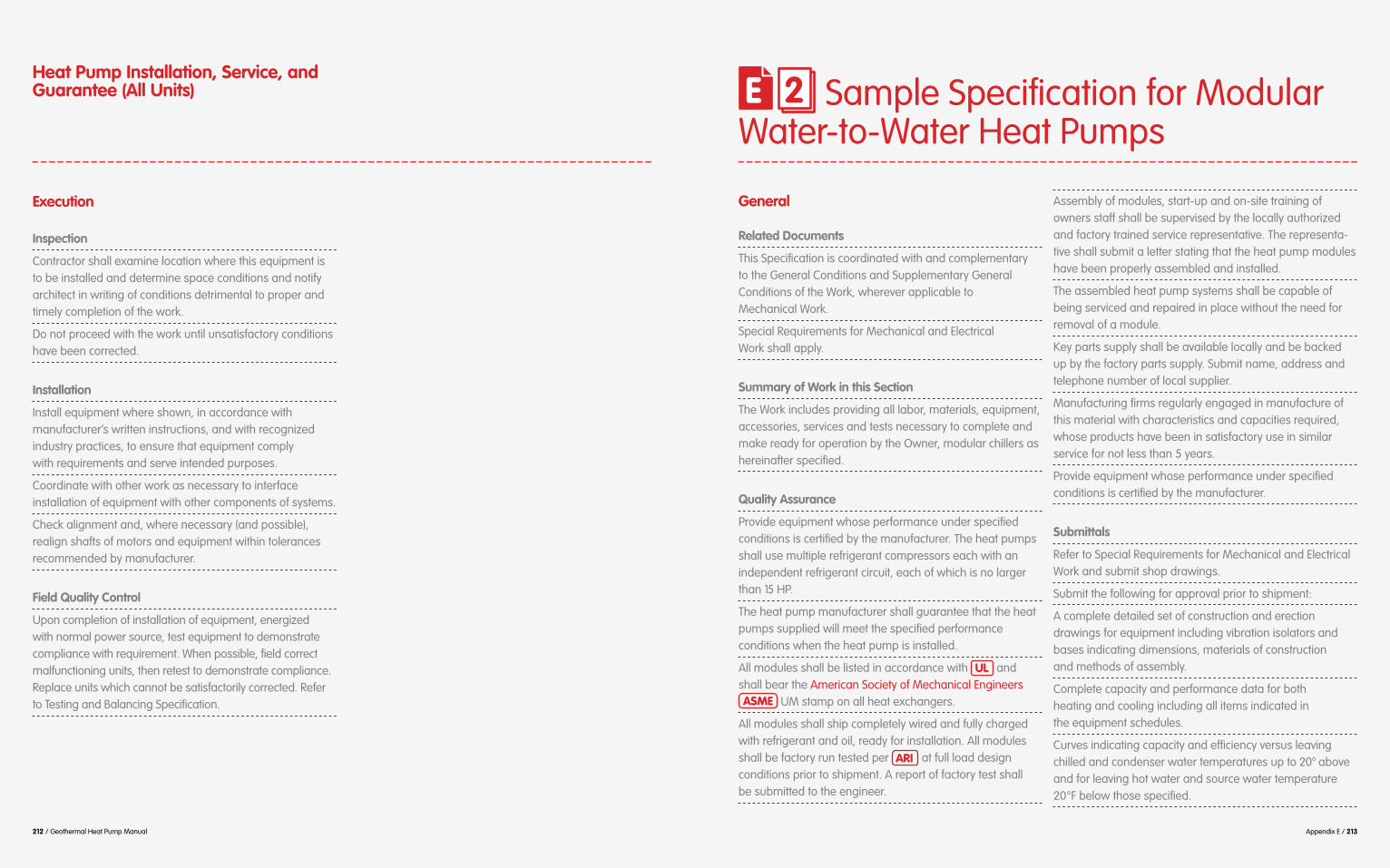
212 / Geothermal Heat Pump Manual Appendix E / 213
Heat Pump Installation, Service, and Guarantee (All Units) E 2 Sample Specification for Modular
Water-to-Water Heat Pumps
Execution Inspection
Contractor shall examine location where this equipment is to be installed and determine space conditions and notify architect in writing of conditions detrimental to proper and timely completion of the work.
Do not proceed with the work until unsatisfactory conditions have been corrected.
Installation
Install equipment where shown, in accordance with manufacturer’s written instructions, and with recognized industry practices, to ensure that equipment comply with requirements and serve intended purposes.
Coordinate with other work as necessary to interface installation of equipment with other components of systems.
Check alignment and, where necessary (and possible), realign shafts of motors and equipment within tolerances recommended by manufacturer.
Field Quality Control
Upon completion of installation of equipment, energized with normal power source, test equipment to demonstrate compliance with requirement. When possible, field correct malfunctioning units, then retest to demonstrate compliance. Replace units which cannot be satisfactorily corrected. Refer to Testing and Balancing Specification.
General Related Documents
This Specification is coordinated with and complementary to the General Conditions and Supplementary General Conditions of the Work, wherever applicable to Mechanical Work.
Special Requirements for Mechanical and Electrical Work shall apply.
Summary of Work in this Section
The Work includes providing all labor, materials, equipment, accessories, services and tests necessary to complete and make ready for operation by the Owner, modular chillers as hereinafter specified.
Quality Assurance
Provide equipment whose performance under specified conditions is certified by the manufacturer. The heat pumps shall use multiple refrigerant compressors each with an independent refrigerant circuit, each of which is no larger than 15 HP.
The heat pump manufacturer shall guarantee that the heat pumps supplied will meet the specified performance conditions when the heat pump is installed.
All modules shall be listed in accordance with UL and shall bear the American Society of Mechanical Engineers ASME UM stamp on all heat exchangers.
All modules shall ship completely wired and fully charged with refrigerant and oil, ready for installation. All modules shall be factory run tested per ARI at full load design conditions prior to shipment. A report of factory test shall be submitted to the engineer.
Assembly of modules, start-up and on-site training of owners staff shall be supervised by the locally authorized and factory trained service representative. The representa-tive shall submit a letter stating that the heat pump modules have been properly assembled and installed.
The assembled heat pump systems shall be capable of being serviced and repaired in place without the need for removal of a module.
Key parts supply shall be available locally and be backed up by the factory parts supply. Submit name, address and telephone number of local supplier.
Manufacturing firms regularly engaged in manufacture of this material with characteristics and capacities required, whose products have been in satisfactory use in similar service for not less than 5 years.
Provide equipment whose performance under specified conditions is certified by the manufacturer.
Submittals
Refer to Special Requirements for Mechanical and Electrical Work and submit shop drawings.
Submit the following for approval prior to shipment:
A complete detailed set of construction and erection drawings for equipment including vibration isolators and bases indicating dimensions, materials of construction and methods of assembly.
Complete capacity and performance data for both heating and cooling including all items indicated in the equipment schedules.
Curves indicating capacity and efficiency versus leaving chilled and condenser water temperatures up to 20° above and for leaving hot water and source water temperature 20°F below those specified.

214 / Geothermal Heat Pump Manual Appendix E / 215
Sample Specifications for Modular Water-to-Water Heat Pumps
Sample Specifications for Modular Water-to-Water Heat Pumps
Equipment sound levels in each of the eight octave bands based on readings taken and reported in accordance with ASHRAE Standard 36-72, 1972 Measurement of Sound Power Radiated from Heating, Refrigerating and Air Conditioning Equipment.
Electrical wiring diagram.
Manufacturer shall review the modular control sequence specified and provide a written statement indicating that the sequence is acceptable or provide alternative recommenda-tions. After the automatic temperature control shop drawings are complete, the manufacturer shall review the shop drawings as they apply to controlling the heat pump units and provide written approval of the shop drawings.
Operating Instructions and Training
After completion of all work and all tests and at such time as designated by the Architect, provide the necessary skilled personnel to operate the entire installation for a period of two (2) consecutive days eight (8) hours each for$cooling (during the cooling season) and two (2) consecutive days eight (8) hours each for heating (during the heating season) and two additional days to be scheduled by the Owner.
During the operating period, fully instruct the Owner’s representative in the complete operation, adjustment and maintenance of the entire installation.
All training shall be by factory authorized representatives, fully trained in the systems and the equipment operation and maintenance. The Contractor shall schedule the first day and the Owner shall schedule the other days. The additional days shall be scheduled within 1 year of the second two days of training.
Running Test of Heat Pump System B92#&$2"#$	&*:#&/2*'($#P,*34#(27$3*3*(:$/(-$/55#++'&*#+$"/K#$0##($2#+2#-$/(-$*(+,./2*'($/33.*#-7$&,($2"#$#(2*&#$+1+2#4$9'&$/($^D"',&$3#&*'-$*($0'2"$5''.*(:$/(-$"#/2*(:$4'-#A$U,($2#+2*(:$+"/..$0#$-'(#$-,&*(:$2"#$5''.*(:$+#/+'($/(-$/:/*($-,&*(:$2"#$"#/2*(:$+#/+'(A$R,&*(:$$2"*+$2*4#7$*(2&'-,5#$,3+#2+$*($/..$5'(2&'.$-#K*5#+$2'$$5"#56$2"#*&$'3#&/2*'(A$B92#&$/..$-#K*5#+$"/K#$0##($2#+2#-$/(-$5'(2&'.$+1+2#4$3&'K#-$2'$9,(52*'($+/2*+9/52'&*.17$$&#+#2$2"#$5'(2&'.+$2'$2"#$3&'3#&$+#22*(:+$/+$-*4#-$01$2"#$B&5"*2#52A$!"#$2#+2$'9$2"#$'K#&/..$3#&9'&4/(5#$+"/..$0#$-'(#$*($2"#$3&#+#(5#$'9$2"#$"#/2$3,43$4/(,9/52,&#&$/(-$2"#$M8(#&Z+$&#+#(2/2*K#+A$B92#&$2"#$5'(2&'.+$"/K#$0##($2#+2#-$/(-$3&'K#-$+/2*+9/52'&17$2"#$+1+2#4$+"/..$$0#$&,($,(-#&$/,2'4/2*5$5'(2&'.$/(-$2"#$9'..'8*(:$-/2/$+"/..$0#$.'::#-$f$'&2;
Outside dry bulb and wet bulb temperatures.
Chilled (hot) water supply and return temperatures for the primary loop and each module.
Ampere nameplate rating of each compressor.
Actual ampere reading and voltage for each compressor.
Source/sink water supply and return temperatures.
Compressor refrigerant suction pressure and temperatures.
Compressor refrigerant discharge pressure and temperatures.
Suction and discharge pressure at each water pump.
Water pressure drop across condenser and chiller.
Water pressure drop across water strainers when the strainers are clean.
Guarantee
The manufacturer guarantees by his acceptance of the Contract that the equipment provided shall be free from any and all defects and that all apparatus will develop capaci-ties and characteristics specified, and that if during a period of one year from date of shipment and as extended below any such defects in workmanship, material or performance appear, he shall immediately replace, repair, or otherwise correct the defect or deficiency without cost to the Owner within a reasonable time. The guarantee period must include one continuous cooling season from May 1st to October 1st, and one continuous heating season December 1st to March 30th.
This Article is general in nature and will not waive stipula-tions of other claims which specify guarantee periods in excess of one (1) year.
One year parts only warranty shall be furnished as standard. Four year extension of the compressor warranty shall be included.
Products Description
Furnish and install modules as indicated on the drawings of water-to-water heat pumps.
General
Equipment shall be completely assembled, piped, internally wired, fully charged with HCFC-22 (CONSIDER ALTERNATE REFRIGERANT SUCH AS R410a) and test operated at the factory. A controls field interface terminal strip and all safety controls shall be furnished, installed and tested by the unit manufacturer. The unit shall be rated in accordance with ISO-ARI 13256-2.
The system’s water inlet and outlet for the source and load-side connections shall be female NPT composed of copper. Service and caution labels shall be placed on the unit in their appropriate locations.
Cabinet
Unit casing shall be constructed of zinc coated, heavy gauge, and galvanized steel. Access to the refrigerant and controls shall be provided through the front, access panels.
All panels shall be insulated with 2” thick dual density bonded glass fiber. The insulation shall meet the erosion requirements of UL 181. It shall have a flame spread of less than 25 and a smoke developed classification of less than 50 per ASTM-84 and UL 723.
The unit shall be installed for proper access. Procedures for proper access inspection and cleaning of the unit shall be included in the maintenance manual.
Note that unit access, mounting and maintenance clear-ance is different for each manufacturer. The number of modules and layout will vary with manufacturer. The layout shown on the drawings is based on Compax. The Contrac-tor is responsible for layout out alternate manufacturers in compliance with their requirements. Submit layout drawings for review and approval.
Compressors
Vibration isolation shall be provided through rubber mount-ing devices located underneath the compressor. Internal thermal overload protection shall be provided. Protection against excessive discharge pressure shall be provided by means of a high-pressure switch. A loss of charge shall be detected by a low pressure safety.

216 / Geothermal Heat Pump Manual Appendix E / 217
Sample Specifications for Modular Water-to-Water Heat Pumps
Sample Specifications for Modular Water-to-Water Heat Pumps
Refrigerant Tubing
The refrigerant tubing shall be of 99% pure copper. This system shall be free from contaminants and conditions such as drilling fragments, dirt and oil.
Refrigerant Circuits
The refrigerant circuit shall contain a thermal expansion valve. Service pressure ports shall be factory supplied on the high and low pressure sides for easy refrigerant pressure or temperature testing.
Reversing Valve
The reversing valve shall be a pilot operating, sliding piston type with a replaceable, encapsulated magnetic coil. The reversing valve shall be energized in the cooling cycle.
Water-to-Refrigerant Heat Exchangers
The water-to-refrigerant heat exchangers shall be of a high quality, coaxial coil for maximum heat transfer. The source-side heat exchanger shall be constructed of copper metal (COORDINATE MATERIAL WITH POSSIBLE GROUND WATER CONTAMINENT). The load-side heat exchanger shall be constructed of copper. Both heat exchangers shall be deeply fluted to enhance heat transfer and minimize fouling and scaling. The coil shall have a working pressure of 500 psig on the refrigerant side and 400 psig on the waterside. Provide an 800 micron mesh strainer at the inlet to the source side heat exchanger.
Electrical $
2'$/..'8$"#/2*(:$/(-$5''.*(:$'3#&/2*'($2'$'55,&$9&'4$2"#$%B@$5'(2&'..#&A$!"#+#$-#K*5#+$+"/..$0#$/+$9'..'8+;$
A 24 VAC energy limiting class II 100 VA transformer.
A 24 VAC compressor contactor for compressor control.
Field control connections shall be provided for ease of hookup to a terminal strip located in the unit’s control box.
A lockout relay, which controls cycling of the compressor, shall be provided to protect the compressor during adverse operating conditions.
A high pressure switch shall be provided to protect the compressor against operation at refrigerant system pressure exceeding 395 psig.
A low pressure switch shall provide freeze protection to the compressor below 20°F suction.
Nameplate information shall be provided for the application of either time-delay fuses or HACR circuit breakers for branch circuit protection from the primary source of power.
Controls !"#$5'(2&'.$3/56/:#$9'&$#/5"$,(*2$+"/..$0#$3&'K*-#-$8*2"$$/$HOO$aB$2&/(+9'&4#&$8*2"$/$5*&5,*2$0&#/6#&A$!"#$5'(2&'..#&$+"/..$*(5.,-#$/$.'56',2$&#./17$/(2*D+"'&2$515.#$5'43&#++'&$3&'2#52*'(7$&/(-'4$+2/&2$-#./17$0&'8(',2$3&'2#52*'(7$.'8$3&#++,&#$2*4#$-#./17$5'43&#++'&$-#./1$'($+2/&27$U!R$2#43#&/2,&#$+#(+'&+$/2$2"#$*(.#2$/(-$',2.#2$'9$2"#$+',&5#b+*(6$/(-$.'/-$+*-#+$'9$#/5"$4'-,.#$/(-$2#&4*(/.$$5'((#52*'(+$9'&;$
A flow switch in the load and source/sink sides to shut down unit when there is insufficient flow.
A heat and a cool switch to control the operating mode of each unit from the building management system BMS .
Dry contact connections for alarm indication (to be connected to the BAS).
Dry contact connections for pump starting to be used to control automatic load side and source/sink side isolation valves for each module.
LED, light emitting diodes, display shall also be included for diagnostics of each unit via alphanumeric messages and providing menu selection of operating and override parameter and indication of alarms.
Ball Valves
Ball valves shall be furnished and field installed between the unit and the supply and return lines of the loop to stop water flow to the unit in a maintenance or service situation.
Automatic Isolation Valve
Provide an automatically controlled isolation valve in the load side and the sour/sink side which shall open when a module is activated.
Controls
The heat pump modules shall be controlled in a staged manner to satisfy the building load. Controls shall be as described in the specification. The individual module controllers and control panels shall provide for the sequence of operation as described in the specification.
Execution Inspection
Contractor shall examine location where his equipment is to be installed, determine space conditions and notify Architect, in writing, of conditions detrimental to proper and timely completion of the work. Do not proceed with the work until unsatisfactory conditions have been corrected.
Installation
Install equipment where shown in accordance with manufacturer’s written instructions and with recognized industry practices, to ensure that equipment complies with requirements and serves intended purposes.
A field qualified, factory trained, manufacturer’s representative shall be present on site during all critical periods of the installation. Upon completion of the installation, the Contractor shall furnish a certificate from the heat pump manufacturer stating that the installation has been made in accordance with the manufacturer’s installation requirements.
Coordinate with other work as necessary to interface installation of equipment with other components and systems.
Site Preparation
During the preparation of the site for installation of the modular heat pump, piping to be installed before the modules are set in place or before water side connections are made to the heat pump shall be coordinated with final location of the heat pump.

Appendix F / 219 218 / Geothermal Heat Pump Manual
Sample Specifications for Modular Water-to-Water Heat Pumps Appendix F – Sample of Pre-functional
Checklist and Start-up Checklist
FThe Contractor shall provide strainers at the inlet of the water systems to each heat pump, the supply and return mains shall be temporarily connected with flexible hose and water circulated through the system in order to remove as much debris as possible prior to the installation of the heat pump.
Perform this clean up before installation of the heat pumps.
Field Quality Control
Upon completion of installation of equipment and after the motors have been energized with normal power source, test equipment to demonstrate compliance with require-ments. When possible, field correct malfunctioning units, then retest to demonstrate compliance. Replace units which cannot be satisfactorily corrected. Refer to Testing and Balancing Specifications.

Appendix F / 221 220 / Geothermal Heat Pump Manual
F 1 Sample of Pre-functional Checklist and Start-up Checklist
Pre-functional Checklist
Heat Pump Unit, tag: UNIT ID# Components included: __ supply fans __ return & exhaust fans, __ coils, __ valves __ VFD __ dampers, __ compressors __ condensers
Submittal/Approvals Submittal
The above equipment and system integral to them are complete and ready for functional testing. The checklist items are complete and have been checked off only by parties having direct knowledge of the event, as marked below, subject to an attached list of outstanding items yet to be completed. A Statement of Correction will be submitted upon completion of any outstanding areas. None of the outstanding items preclude safe and reliable functional tests being performed.
Pre-functional checklist items are being completed as part of post construction Commissioning work, preparatory to functional testing.
This checklist does not take the place of the manufacturer’s recommended checkout and startup procedures or report.
Items that do not apply are noted with the reasons on this form ( N/A = not applicable, BO = by others).
If this form is not used for documenting, one of similar rigor shall be used.
Contractors assigned responsibility for section of the checklist shall be responsible to see that checklist items by their subcontractors are completed and checked off.
“Contr.” column or abbreviations in brackets to the right of an item refer to the contractor responsible to verify completion of this item.
Approvals
This filled-out checklist has been reviewed. Its completion is approved with the exceptions noted below.
Mechanical Contractor MC Controls Contractor CCDate Date
Date Date
Date
Date
Date
Date
Electrical Contractor EC Sheet Metal Contractor SC
TAB Contractor TAB
Commissioning Agent CxA
Notes:
General Contractor GC
Owner’s Representative OR
Step 1 Submittals/Approvals
Architect
All Contractors
Commissiong Agent
Controls Contractor
Electrical Contractor
General Contractor
Mechanical Contractor
Sheet Metal Contractor
Test/Balance Contractor
Owner’s Representative
A/E
ALL
CxA
CC
EC
GC
MC
SC
TAB
OR

222 / Geothermal Heat Pump Manual Appendix F / 223
Manufacturer’s cut sheets
Sequences and control strategies
Performance data (fan curves, coil data, etc.)
Q&M manuals
Documentation complete as per contract documents for given trade: ___Yes ___No
Installation and start-up manual and plan
Step 2 Requested Documentation Submitted
Check
Equip
Ta
g>WSH
P ID#
WSHP I
D#
WSHP I
D#
Manufacturer
Model
Serial #
Cooling Capacity
Heating Capacity
Fan Capacity
1
2
3
1
2
3
1
2
3
1
2
3
1
2
3
1
2
3
The equipment installed matches the specifications for given trade: ___Yes ___No
Step 3 Model Verification
Equip
Tag>
WSHP I
D#
WSHP I
D#
WSHP I
D#
1=Specified 2=as submitted 3=as installed. Enter information and check if okay. Enter note number if deficient

224 / Geothermal Heat Pump Manual Appendix F / 225
General Installation
Cashing in good condition: no dents, leaks, door gasket installed
Unit is serviceable (mechanical clearances provided according to manufacturer requirement)
All the unit access panels are secure and in place
Low/high-side pressure temperature caps are secure and in place
Heat transfer fluid has been added in the proper mix to prevent freezing in the closed-loop
Sound attenuation installed
Boot between duct and unit is tight and in good condition
The thermostat is in the OFF position
Vibration isolation is provided
Step 4a Installation Checks
Check
Equip
Ta
g>WSH
P ID#
WSHP I
D#
WSHP I
D#
Enter information and check if okay Enter note number if deficient
Enter information and check if okay Enter note number if deficient
Instrumentalization installed according to specification (zone thermostat installed in a good location and connected accordingly)
Vibration isolation is provided
Pipes properly insulated
Filters installed and replacement type and efficiency permanently affixed to housing; construction filters removed
Strainer in place and clean
Clean up of equipment completed per contract documents
Pipes properly labeled
Valved Piping and Coils
Piping system properly flushed
Pipe fitting complete and pipes properly supported
Step 4b Installation Checks
Check
Equip
Ta
g>WSH
P ID#
WSHP I
D#
WSHP I
D#

226 / Geothermal Heat Pump Manual Appendix F / 227
No leaking apparent around fittings
All coils are clean and find are in good condition
P/T plugs and isolation valves installed per drawings
Condensate line trap installed per manufacturer
Sensors calibrated (See calibration section below)
All condensate drain pans clean and slope to drain per spec
Air and Water sensors properly located and secure
Valves properly tagged
Measures taken to deal with condensation, especially if fan will cycle
Valves installed in proper direction
Check
Equip
Ta
g>WSH
P ID#
WSHP I
D#
WSHP I
D#
Step 4c Installation Checks
Ducts (preliminary check)
Sound attenuators installed
Balancing dampers installed as per drawings and TAB’s site visit
No apparent severe duct restrictions
Electric and Controls
Duct joint sealant properly installed
Outside air capability to space serviced by FCU installed
Pressure leakage tests completed
High voltage power supply is correct and in accordance with the nameplate rating
Ducts cleaned as per specifications
Check
Equip
Ta
g>WSH
P ID#
WSHP I
D#
WSHP I
D#
Step 4d Installation Checks
Enter information and check if okay Enter note number if deficient
Enter information and check if okay Enter note number if deficient

228 / Geothermal Heat Pump Manual Appendix F / 229
The field wiring and circuit protection is the correct size
All electric connections right
Safeties installed and safe operating ranges for this equipment provided to the commissioning agent
Safeties in place and operable
Proper grounding installed for unit
Functional test procedures for this equipment reviewed and approved by installing contractor
The low voltage control circuit wiring correct per the unit wiring diagram
Final
Step 4e Installation Checks
Check
Equip
Ta
g>WSH
P ID#
WSHP I
D#
WSHP I
D#
The checklist items of step 4 are successfully completed for given trade: ___Yes ___No
Fan rotation verified
Fan has no unusual noise or vibration
Startup report completed with this checklist attached
Air/water flow and air/water pressure drop verified
Unit voltage and aps verified-each phase
Specified sequences of operation and operating schedules have been implemented with all variations documented
Specified point-to-point checks have been completed and documentation record submitted for this system
Step 5 Operational Checks
Check
Equip
Ta
g>WSH
P ID#
WSHP I
D#
WSHP I
D#
The checklist items of part 5 are successfully completed for given trade: ___Yes ___No
These augment MFRS list. This is not the functional performance testing Enter information and check if okay Enter note number if deficient
Enter information and check if okay Enter note number if deficient

230 / Geothermal Heat Pump Manual Appendix F / 231
$LMF$/(-$3&#++,&#$+#(+'&+$/(-$:/:#+7$/(-$/..$/52,/2'&+$Y-/43#&+$/(-$K/.K#+[$'($2"*+$3*#5#$'9$#P,*34#(2$+"/..$0#$5/.*0&/2#-$,+*(:$2"#$4#2"'-+$/(-$2'.#&/(5#+$:*K#($*($2"#$L/.*0&/2*'($/(-$X#/6D01$!#+2$G&'5#-,&#+$-'5,4#(2A$$
8*2"*($2"#$./+2$HF$4'(2"+;$]b\ggggggA$@#(+'&+$*(+2/..#-$$
Step 6 Sensor and Actuator Calibration
Sens
or or
Actuator
& Lo
catio
n
Loca
tion O
K
1st G
age or
BAS V
alue
Instr.
Measu
red
Value Fin
al Gage o
r
BAS V
alue
Pass
Y/N
The Contractor’s own sensor check-out sheets may be used in lieu of the above, if the same recording fields are included and the referenced procedures are followed. All censors are calibrated within required tolerances: ___Yes ___No
Gage reading = reading of the permanent gage on the equipment. BMS = building management system Instr. = testing instrument. Visual = actual observation.
Step 7 Start-up Checklist and Log
Functional Test (Start-Up )Attached below is a typical start-up and log form. The form records all components of a geothermal system and provides the engineer,
that the geothermal system was properly installed and integrated.
Initial Unit Start-up @2/&2$,3$9'&$0/+*5$5'(2&'.+$*+$*(5.,-#-$0#.'8;
__ 1. Set the thermostat to the highest position.
__ 2. Set the thermostat system switch to COOL with the fan control to AUTO. The compressor should NOT run.
__ 3. Reduce the temperature control setting until the compressor, reversing valve, solenoid valve, and loop pump are energized.
__ 4. Adjust water flow utilizing pressure/temperature plugs and comparing to tables contained in specification sheet data from manufacturer. Water leaving the heat exchanger should be warmer than the entering water temperature (approximately 9°F - 12°F); blower operation should be smooth; compressor and blower amps should be within data plate ratings; the suction line should be cool with no frost observed in the refrigerant circuit.
__ 5. Check the cooling refrigerant pressures against values in operating pressures table provided by the manufacturer. Use the start-up checklist and log form to record readings.
__ 6. Turn the thermostat switch to the OFF position. Unit should stop running and reversing valve should de-energize.
__ 7. Leave unit off for approximately FIVE (5) minutes to allow pressure equalization.
__ 8. Turn the thermostat to the lowest setting.
__ 9. Set the thermostat system switch to the HEAT position.
__ 10. Adjust the temperature setting upward until the unit is energized. Warm air should blow from the register. A water temperature decrease of approximately 5°F-9°F leaving the heat exchanger should be noted. The blower and compressor operation should be smooth with no frost observed in the refrigeration circuit.
__ 11. Check the heating refrigerant pressures against values in operating pressures table provided by the manufacturer. Use the start-up checklist and log form to record readings.
__ 12. Set the thermostat to maintain the desired space temperature.
__ 13. Instruct the owner on system operation.

232 / Geothermal Heat Pump Manual Appendix F / 233
Step 8a Installing Contractor
Use this form to thoroughly check-out the system and units before and during start-up. (This form need not be returned to the factory unless requested during technical service support).
Mechanical Contractor:
Model Number:
Date:
Serial Number:
In order to minimise troubleshooting and costly system failures, complete the following checks and data entries before the system is put into full operation.
Step 8b Installing Contractor
Entering fluid temperature [°F]
Temperature differential [°F]
Return-air temperature DB/WB [°F]
Water coil heat exchanger (Water pressure out) [PSIG]
Pressure Differential [PSIG]
Leaving fluid temperature [°F]
Water coil heat exchanger (Water pressure in) [PSIG]
Supply-air temperature [°F]
Mode
Heat S
ource
Heat L
oad
Cool S
ource
Cool Lo
ad
Compressor
Volts [V]
Discharge line temperature(after 10 minutes) [°F]
Amps [A]
PSIG = pound-force per square inch gauge

234 / Geothermal Heat Pump Manual Appendix G / 235 0234 / Geothermal Heat Pump Manual
Appendix G Selected Glossary and References
GG 1 Selected Glossary
A
Ambient
@,&&',(-*(:$#(K*&'(4#(2/.$5'(-*2*'(+
Aquifer
<&/52,&#-$0#-&'56$'&$,(5'(+'.*-/2#-$
3#&4#/0.#$2'$1*#.-$#5'('4*5/..1$
$B
Bedrock
!"#$+'.*-$&'56$2"/2$,(-#&.*#+$+'*.$'&$'2"#&$,(5'(+'.*-/2#-$4/2#&*/.A
Bleed
5'.,4($8#..$2"/2$*+$('2$,&(#-$2'$$2"#$/P,*9#&A
Borehole
B$5*&5,./&$"'.#$-&*..#-$*(2'$2"#$:&',(-A
British Thermal Unit
$'9$"#/2$(##-#-$2'$&/*+#$2"#$2#43#&/D2,&#$'9$'(#$3',(-$'9$8/2#&$'(#$
$2'$*(-*5/2#$2"#$"#/2*(:$/(-$5''.*(:$5/3/5*21$'9$/$+1+2#47$*(5.,-*(:$"#/2$.'++$/(-$:/*(A
Building Management System
B$5'43,2#&$0/+#-$+1+2#4$*(+2/..#-$$*($/$0,*.-*(:$2'$5'(2&'.$/(-$4'(*2'&$#(#&:1$,+#$/(-$'2"#&$9,(52*'(/.$&#P,*#(2+A
$
C
Coefficient of Performance
B$&/2*'$'9$2"#$"#/2$#)2&/52#-$2'$2"#$#(#&:1$5'(+,4#-$*($2"#$3&'5#++A
Cone of Depression
B$-#3&#++*'($*($2"#$8/2#&$2/0.#$'&$3'2#(2*'4#2&*5$+,&9/5#$2"/2$"/+$2"#$+"/3#$'9$/($*(K#&2#-$5'(#7$/(-$-#K#.'3+$/&',(-$/$8#..$9&'4$8"*5"$
$D
Drawdown
R*+2/(5#$0#28##($2"#$+2/2*5$8/2#&$.#K#.$/(-$2"#$+,&9/5#$'9$2"#$5'(#$$'9$-#3&#++*'(A
$F
Fault
B$9&/52,&#$'&$S'(#$'9$9&/52,&#+$/.'(:$8"*5"$2"#&#$"/+$0##($-*+3./5#4#(2$$'9$2"#$+*-#+$&#./2*K#$2'$'(#$/('2"#&$3/&/..#.$2'$2"#$9&/52,&#A
Filter Pack
@/(-$'&$:&/K#.$2"/2$*+$+4''2"7$,(*9'&47$5.#/(7$8#..D&',(-#-$/(-$+*.*5#',+$2"/2$*+$3./5#-$*($2"#$/((,.,+$'9$2"#$8#..$+5&##($2'$3&#K#(2$9'&4/D2*'($4/2#&*/.$9&'4$#(2#&*(:$2"#$+5&##(A
Fracture
B$5&/567$V'*(27$9/,.2$'&$'2"#&$0&#/6$$*($&'56+A
$G
Geology
@2,-1$'9$2"#$3./(#2$#/&2"7$*2+$5'43'+*D2*'(7$+2&,52,$9'&4/2*'(7$/(-$"*+2'&1A
Geothermal Energy
!"#$#/&2"Z+$*(2#&*'&$"#/2$4/-#$/K/*./0.#$2'$4/($01$#)2&/52*(:$*2$$9&'4$"'2$8/2#&$'&$&'56+A
Geothermal Heat Pump
Q#/2*(:$/(-$5''.*(:$-#K*5#+$2"/2$$2/6#$/-K/(2/:#$'9$2"#$&#./2*K#.1$5'(+2/(2$2#43#&/2,&#$'9$2"#$#/&2"Z+$*(2#&*'&7$,+*(:$*2$/+$/$+',&5#$'&$+*(6$$9'&$"#/2A$C"#($5''.*(:7$"#/2$*+$#)2&/52#-$9&'4$2"#$+3/5#$/(-$-*++*D3/2#-$*(2'$2"#$#/&2"`$8"#($"#/2*(:7$"#/2$*+$#)2&/52#-$9&'4$2"#$#/&2"$/(-$3,43#-$*(2'$2"#$+3/5#A
Gneiss
B$5',&+#D:&/*(#-$&#:*'(/.$4#2/4'&D3"*5$&'56$2"/2$+"'8+$5'43'+*2*'(/.$0/(-*(:$/(-$3/&/..#.$/.*:(4#(2$'9$4*(#&/.+A

236 / Geothermal Heat Pump Manual Appendix G / 237
Granite
B$5',&+#D:&/*(#-7$*(2&,+*K#$*:(#',+$&'56$5'43'+#-$'9$P,/&2S7$'&2"'5./+#$9#.-+3/&7$3./:*'5./+#$9#.-+3/&7$/(-$4*5/+A$B.+'7$+'4#2*4#+$/$4#2/4'&D3"*5$3&'-,52A
Ground Coupling
B($/&&/(:#4#(2$'9$3*3*(:$/(-$$$
2'$#)5"/(:#$"#/2$8*2"$2"#$$#/&2"Z+$*(2#&*'&A
Ground water
C/2#&$*($2"#$+/2,&/2#-$S'(#$2"/2$*+$,(-#&$3&#++,&#$#P,/.$2'$'&$:&#/2#&$2"/($/24'+3"#&*5$3&#++,&#A
Grout
$'9$/$5'(+*+2#(51$2"/2$5/($0#$9'&5#-$2"&',:"$/$3*3#$/(-$3./5#-$/+$&#DP,*&#-A$>($8#..$5'(+2&,52*'(7$*2$*+$3./5#-$0#28##($2"#$5/+*(:$/(-$2"#$+*-#+$'9$2"#$8#..$0'&#$2'$/$3&#-#2#&D4*(#-$"#*:"2$/0'K#$2"#$0'22'4$'9$$2"#$8#..7$+#5,&*(:$2"#$5/+*(:$*($3./5#$
9&'4$2"#$8#..$0'&#A
$
Selected Glossary
H
Heat Exchanger
B$-#K*5#$9'&$2&/(+9#&&*(:$2"#&4/.$
Heat Pump
B$-#K*5#$,+#-$9'&$"#/2*(:$/(-$5''.*(:$8"*5"$'3#&/2#+$01$4'K*(:$"#/2$9&'4$5''.#&$2'$/$8/&4#&$.'5/2*'($/(-$K*5#$K#&+/7$01$#)2&/52*(:$"#/2$9&'4$2"#$$/*&7$8/2#&$'&$#/&2"A
Hydrogeology
!"#$+5*#(5#$2"/2$-#/.+$8*2"$+,0+,&D9/5#$8/2#&+$/(-$8*2"$2"#$&#./2#-$:#'.':*5$/+3#52$'9$+,&9/5#$8/2#&A
$I
Igneous Rocks
<'&4#-$01$5&1+2/..*S/2*'($'9$./K/$$'&$*2+$+,0+,&9/5#$3/&#(2$4/2#&*/.7$4/:4/7$2"/2$4/1$'&*:*(/2#$9&'4$$2"#$#/&2"Z+$4/(2.#$'&$/+$/$&#+,.2$$'9$4#2/4'&3"*+4A
M
Marble
B$4#2/4'&3"*5$&'56$3&#-'4*(/(2.1$
&1+2/..*S#-$5/.5*2#$/(-b'&$-'.'4*2#A
Metamorphic Rock
@#-*4#(2/&17$*:(#',+$'&$'.-#&$4#2/4'&3"*5$&'56+$2"/2$"/K#$0##($5"/(:#-$01$#)2#$2#43#&/2,&#+$/(-$3&#++,&#+$&#+,.2*(:$*($(#8$4*(#&/.+$/(-$2#)2,&#+$'9$2"#$&'56A
Moraine
B$4',(-$'&$&*-:#$'9$/55,4,./2#-7$
$01$-*4$/52*'($'9$:./5*/.$*5#A
O
Outwash Deposits
@*.2$/(-$5./1$-#3'+*2#-$9&'4$+,+3#(D
2"/2$5/(('2$0#$5'(2/*(#-$8*2"*($2"#$+2&#/4$5"/((#.A
Selected Glossary
P
Permeability
!"#$3&'3#&21$'&$5/3/5*21$'9$/$3'&',+$&'567$+#-*4#(2$'&$+'*.$9'&$2&/(+4*22*(:$
Pumping Test
-#2#&4*(#$/P,*9#&$'&$8#..$$5"/&/52#&*+2*5+A
R
Recharge
>($"1-&'.':17$2"#$.#(*+"4#(2$$'9$:&',(-$8/2#&$2'$2"#$S'(#$'9$$+/2,&/2*'(A
Runoff
!"#$/4',(2$'9$&/*($-*4.1$.#/K*(:$/($/&#/$*($+,&9/5#$-&/*(/:#7$/+$'33'+#-$2'$2"#$/4',(2$2"/2$+##3+$',2$/+$:&',(-$8/2#&A
S
Schist
B$4#2/4'&3"*57$5&1+2/..*(#$&'56$5"/&/52#&*S#-$01$+2&'(:$9'.*/2*'($/(-$3/&/..#.*+4$'9$JOe$'9$*2+$4*(#&/.+A
Sedimentary Rock
U'56+$9'&4#-$01$5'(+'.*-/2*'($'9$.''+#$+#-*4#(2+$*(2'$./1#&+A
Soil
!"#$./1#&$'9$4/2#&*/.$/2$./(-$+,&9/5#$2"/2$+,33'&2+$3./(2$:&'82"A
T
Thermal Conductivity
B$4#/+,&#$'9$/$&'56Z+$5/3/5*21$9'&$"#/2$5'(-,52*'(
Till
$01$/$:./5*#&$8*2"',2$'&6*(:$01$4#.28/2#&7$/(-$5'(+*+2*(:$'9$/$4*)2,&#$'9$5./17$+*.27$+/(-7$:&/K#.7$/(-$0',.-#&+$&/(:*(:$8*.-.1$*($+*S#$/(-$
-&,4.*(+7$/(-$4'&/*(#+$+,5"$/+$2"#$U'(6'(6'4/$/(-$Q/&0'&$Q*..$$4'&/*(#+$'9$X'(:$>+./(-A
W
Water Table
!"#$+,&9/5#$'9$:&',(-$8/2#&$8"*5"$$*+$/2$/24'+3"#&#*5$3&#++,&#A
Well Logging
B++#++*(:$2"#$:#'.':*57$#(:*(##&*(:7$/(-$3"1+*5/.$3&'3#&2*#+$/(-$5"/&/5D2#&*+2*5+$'9$2"#$+,0+,&9/5#$8*2"$*(+2&,4#(2+$.'8#&#-$*(2'$/$0'&#"'.#A
Well Screen
+#-*4#(2$9&'4$#(2#&*(:$/$8/2#&$8#..A
Well Yield
!"#$K'.,4#$'9$8/2#&$-*+5"/&:#-$9&'4$/$8#..$*($:/..'(+$3#&$4*(,2#A
Z
Zone of Saturation
!"#$+,0+,&9/5#$S'(#$*($8"*5"$/..$2"#$
:&#/2#&$2"/($/24'+3"#&*5$3&#++,&#A

238 / Geothermal Heat Pump Manual Appendix G / 239 239 / Geothermal Heat Pump Manual
Selected Bibliography
MAXA7$HIIIA$@,+2/*(/0*.*21$'9$=&',(-D
@,&K#1$L*&5,./&$HH d7$^d3A$$B+6*(+7$RA7$G'+(#&7$BA7$FOO_A$Q1-&'D:#'.':*5/.$L"/&/52#&*S/2*'($9'&$@*2*(:$=#'2"#&4/.$C#..+$*($<&/52,&#-$%#-&'56$/2$%&'()$h''.':*5/.$G/&67$%&'()7$\#8$]'&6A$B0+2&/52$3&#+#(2#-$
$<&/52,&#-$U'56$L'(9#&#(5#A$$%/+6#&K*..#7$LA$BA7$HII_A$%#-&'56$/(-$
]'&6$L',(21$/(-$G/&2+$'9$i*(:+$/(-$T,##(+$L',(2*#+7$\#8$]'&6$/(-$G/&2+$'9$%#&:#($/(-$Q,-+'($L',(D
@,&K#1$?*+5#../(#',+$>(K#+2*:/2*'(+$@#&*#+$?/3$>DFEOd7$H;F_7OO7$F$3./2#+A$$%/+6#&K*..#7$LA$BA7$HIIFA$%#-&'56$$
L',(21$/(-$G/&2+$'9$\#8$]'&6$/(-$
=#'.':*5/.$@,&K#1$?*+5#../(#',+$>(K#+2*:/2*'($@#&*#+$?/3$>DFOOE7$$$H;F_7OOO7$F$3./2#+A$$%'15#7$GAiA7$<*2S+*44'(+7$RA7$FOOEA$M3#($X''3$=#'2"#&4/.$C#..$@1+D2#4+$'($X'(:$>+./(-;$!#(2"$L'(9#&D#(5#$'($=#'.':1$'9$X'(:$>+./(-$$/(-$?#2&'3'.*2/($\#8$]'&67$X'(:$
G 2 Selected Bibliography
$'9$\#8$]'&67$@2'(1$%&''67$G'+2#&$G&#+#(2/2*'(A$$%&'8(7$LAWA7$C/.2#&7$RABA7$HIIIA$>&'($*($2"#$BP,*9#&$@1+2#4$'9$@,99'.6$
=#'.':*5/.$@,&K#1$C/2#&$U#+',&5#+$>(K#+2*:/2*'(+$U#3'&2$IID_HFd7$HO3A$$%,)2'(7$QA!A7$@'&#(7$WA7$G'+(#&7$BA7$/(-$@"#&('997$GAiA7$HI^HA$U#5'((/*+D+/(5#$'9$=&',(-$C/2#&$U#+',&5#+$$'9$i*(:+$/(-$T,##(+$L',(2*#+7$$
M3#(D<*.#$'&2$^HDHH d7$JI3A$$%,)2'(7$QA!A7$@"#&('997$GAiA7$HIIIA$=&',(-DC/2#&$U#+',&5#+$'9$i*(:+$/(-$T,##(+$L',(2*#+7$X'(:$>+./(-7$
C/2#&D@,33.1$G/3#&$F_I^7$HH_3A$$N$3./2#+A$$$R&*+5'..7$<A=A7$HI^dA$!"#$%&'()*"+(%&+,*--.R*K*+*'(7$@2A$G/,.7$?*((#+'2/7$HO^I3A$$=#'2"#&4/.$Q#/2$G,43$L'(+'&2*,47$
=#'#)5"/(:#$B33.*5/2*'(+7$$3/&#-$9'&$\#8$]'&6$@2/2#$$
$$
W#(6*(+7$WA!A7$FOONA$!$/&*-/%*.++0#"+)1*+2#%.)"$3)/#%+#0+4##5+,*--.++0#"+6*")/3(-+2-#.*&+4##5+!"#$%&+7#$"3*+8*()+9$:5+7;.)*:.7$E&-$
B++'5*/2*'($G&#++A$$$
@,&9/5#+$*($BP,*9#&+$'9$C#+2#&($X'(:$>+./(-7$\#8$]'&6$*($HIJI$/(-$
U#+#/&5"$HINH7$J3A$$$
HINFA$C/2#&$!&/(+4*22*(:$G&'3#&2*#+$'9$BP,*9#&+$'($X'(:$>+./(-7$\#8$
$E$3./2#+A$$$?5T,/1$>(2#&(/2*'(/.7$FOONA$<55-/3(=)/#%+!$/&*+<!+>?=@@AB+!*#)1*":(-+8*()+9$:5+C*./D%+E(%$(-;$?5P,/1$>(2#&(/2*'(/.7$@2/,(2'(7$a*&:*(*/A$$?*+,27$GA7$!#&&/55*/('7$@A7$FOOIA$B(/.1+*+$'9$BP,*9#&$!"#&4/.$/(-$
@,&K#1$>-#/$G&'3'+/.$>OIR7$^3A$$$?'(2*$W&A7$WA7$L",7$BA7$HIINA$C/2#&D!/0.#$B.2*2,-#$*($i*(:+$/(-$T,##(+$L',(2*#+7$\#8$]'&6$*($HIIN7$F3A$"223;bb(1A8/2#&A,+:+A:'Kb3,0+b9+b9+HE_INb9+HE_DINA3-9A$$$
?'(2*$W&A7$WA7$/(-$%,+5*'./('7$UA7$FOOdA$C/2#&D!/0.#$/(-$G'2#(2*'4#2D
D2"17$/(-$X.'1-$BP,*9#&+$%#(#/2"$X'(:$>+./(-7$\#8$]'&67$?/&5"DB3&*.$
$_$+"##2+7$H;HFJ7OOOA$"223;bb(1A*4+A#&A,+:+A:'KbX>4/3+Odb7$"223;bb3,0+A,+:+A:'Kb+*4bEOddb7$"223;bb(1A8/2#&A,+:+A:'Kb3&'V#52+b:*+,(*2bX'(:>+./(-D@>?EOddA"24.A$$$\#8$]'&6$L*21$R#3/&24#(2$'9$R#+*:($/(-$L'(+2&,52*'(7$B,:,+2$FOOFA$$!*#)1*":(-+8*()+9$:5+E(%$(-7$HNd3A$888A(15A:'Kb"24.b--5b-'8(.'/-+b3-9b:#'2"#&4A3-9A$$$M&*'7$LARA7$W'"(+'(7$U##+7$@AWA7$L"*/++'(7$BA7$R#(:7$hA7$@3*2.#&7$WARA7$FOOJA$B$@,&K#1$'9$@2/(-*(:$L'.,4($C#..$>(+2/../2*'(+$*($\'&2"$B4#&*5/;$
HOIDHFHA$$$G#&.4,22#&7$\A?A$B&('87$!A7$HIJEA$=&',(-$C/2#&$*($%&'()7$\#8$]'&6$/(-$U*5"4'(-$L',(2*#+$8*2"$@,4D4/&1$R/2/$'($i*(:+$/(-$T,##(+$L',(2*#+7$\#8$]'&6$L*217$\#8$]'&6;$
=CDEF7$^d3A7$J$3./2#+A$$$
@5",0#&2"7$WALA7$HId^A$F1*+!*#-#D;+#0+G*'+H#"I+2/);+(%&+J%K/"#%.;$!"#$\/2,&/.$Q*+2'&1$G&#++7$EO_3A$$$@'&#(7$WA7$HIN^A$@,0+,&9/5#$=#'.':1$/(-$G/.#':#':&/3"1$'9$T,##(+$
=#'.':*5/.$@,&K#1$C/2#&$U#+',&5#+$>(K#+2*:/2*'(+$NNDE_7$M3#($<*.#$U#3'&27$HN3A$$$@'&#(7$WA7$HI^^A$=#'.':*5$/(-$=#'"1-&'.':*5$U#5'((/*++/(5#$'9$
=#'.':*5/.$@,&K#1$C/2#&$U#+',&5#+$>(K#+2*:/2*'(+$U#3'&2$^ND_O_^7$FF3A7$J$3./2#+A$$$@'&#(7$WA7$HINHA$=&',(-DC/2#&$/(-$=#'"1-&'.':*5$L'(-*2*'(+$*($T,##(+$
=#'.':*5/.$@,&K#1$C/2#&$@,33.1$G/3#&$FOOHDB7$EI3A7$F$3./2#+A$$$@2,447$<A7$L",7$BA7$W'#+2'(7$GAiA7$X/(#$W&A7$WACA7$FOONA$=#'"1-&'.':*5$B++#++4#(2$'9$<&/52,&#-$L&1+2/..*(#$%#-&'56$'($2"#$@',2"#&($G/&2$'9$?/("/22/(7$\#8$]'&6$2"&',:"$2"#$
D3"1+*5/.$?#2"'-+;$WA$=#'3"1+*5+$
$$
@2,447$<A7$L"'8-",&17$@A7$FOOEA$R#.*(#/2*'($'9$=&',(-$C/2#&$<.'8$*($<&/52,&#-$U'56$*($2"#$@',2"8#+2#&($G/&2$'9$?/("/22/(7$\#8$]'&6$
=#'3"1+*5/.$?#2"'-+;$WA$=&',(-$C/2#&$?'(*2'&*(:$f$U#4#-*/2*'($FE7$\'A$E7$3_FD_IA$$$@2,447$<A7$L",7$BA7$X/(:#7$BARA7$G/*..#27$<AXA7$C*..*/4+7$WAQA7$/(-$X/(#$
%'&#"'.#$=#'3"1+*5/.$!#5"(*P,#+$2'$R#.*(#/2#$<&/52,&#-DU'56$=&',(-DC/2#&$<.'8$/(-$<&/52,&#+$B.'(:$C/2#&$!,((#.$</5*.*2*#+$*($\'&2"#&($
=#'.':*5/.$@,&K#1$C/2#&$U$#+',&5#+$>(K#+2*:/2*'(+$OOD_FNd7$HF3A$$$C/.2#&7$RABA7$HIINA$=#'5"#4*+2&1$/(-$?*5&'0*'.':1$'9$>&'(DU#./2#-$
BP,*9#&$%*'9',.*(:$*($@,99'.6$L',(217$D
5/.$@,&K#1$C/2#&DU#+',&5#+$>(K#+2*D:/2*'(+$U#3'&2$IND_OEF7$EN3A

Acknowledgements
Executive Acknowledgements
City of New York$!"#"$%&'()*+,-%(')./)0'""1&($2)?/1'&7$L*21$'9$\#8$]'&6
NYC Department of Design and Construction$3%4+5)6/)07$#(89$<B>B7$L'44*++*'(#&$3%4+5).(:#+,;9$B>B7$R#3,21$L'44*++*'(#&7$$G,0.*5$%,*.-*(:+$R*K*+*'($<$+,)0""$:=8#9 $B++'5*/2#$L'44*++*'(#&7$$
$!#5"(*5/.$@#&K*5#+
Updated and Edited by
NYC Department of Design and Construction – Office of Sustainable Design$>-"1%:)?%+#"9$UB7$R*4'&7$$
$@'(A)?":#($9$G=$B(#58)B%#9 $$Contributors
Kallen & Lemelson, Consulting Engineers, LLP
P.W. Grosser Consulting, Inc.
CRC Commissioning Engineers, PLLC
Book Design
Pentagram$@/)<5C%$5)DE%$%9$G/&2(#&$F(#)3((2%#9$R#+*:(#&$G%$$+()F%C%17$%9$R#+*:($B++*+2/(2$$Peer Reviewers
NYC Department of Design and Construction 3(##+:)@:;+#:9$G=$0$(==)*+''($9 $H%')I7,,%$"9

L'31&*:"2$j$FOHFDFOHE$01$2"#$\#8$]'&6$L*21$R#3/&24#(2$'9$R#+*:($/(-$L'(+2&,52*'($$G,0.*+"#-$01$2"#$\#8$]'&6$L*21$R#3/&24#(2$$'9$R#+*:($/(-$L'(+2&,52*'($
$EODEO$!"'43+'($BK#(,#$X'(:$>+./(-$L*217$\#8$]'&6$HHHOH$NH^AEIHAHOOO$$B..$&*:"2+$&#+#&K#-A$\'$3/&2$'9$2"*+$3,0.*5/2*'($4/1$0#$&'-,5#-7$+2'&#-$*($/$&*#K/.$+1+2#47$'&$2&/(+4*22#-7$$*($/(1$9'&4$'&$01$/(1$4#/(+7$#.#52&'(*57$4#5"/(*5/.7$3"'2'5'31*(:7$'&-*(:7$'&$'2"#&8*+#7$8*2"',2$2"#$3&*'&$3#&4*++*'($'9$2"#$\#8$]'&6$L*21$R#3/&24#(2$'9$R#+*:($/(-$L'(+2&,52*'(A$$R#+*:($01$G#(2/:&/4