Embed Size (px)
Citation preview

Abstract—The most common application of geotextile tubes
can be found in marine engineering. It could be applied as
various structures, such as jetty, submerged breakwater, or
revetment with beneficial features of easy installation,
eco-friendliness and cost-effectiveness. The application of this
method is boomed in recent years. And this project is located at
Al Aqah Beach Fujairah, UAE. Existing rubble groins were
lacked of substantial protection and weakened gradually.
Serious erosion problem was found after Hurricane Gonu. This
disaster affected the local tourism industry significantly. Taking
tourist attractions, project budget, and environmental demands
into consideration, the client chose geotextile tubes to rebuild
the groin and submerged breakwater to achieve the purpose of
beach nourishment.
Index Terms—Geotextile tube, groin, submerged breakwater,
beach nourishment.
I. INTRODUCTION
Shoreline change is a gradual and natural phenomenon; the
longshore current help in managing sediment transport and
keeping the shoreline stable. However, the construction of
man-made structure may break the overall stability [1] of
such phenomenon, making the change of shoreline unstable;
in addition, the occurrence of drifting sand caused by
hurricane has a tremendous impact to the environment. In
2007, Hurricane Gonu hit Fujairah and caused significant
erosion to the coastal beach for some kilometers. Among
which, the Al Aqah beach was found the most serious one.
Although the local longshore current was able to perform
sediment transport from the south to the north and carry to
erosion areas, the natural sedimentation will take years to
restore to the original coastal landform. And possible natural
disasters may cause damage to those areas again while they
are still recovering.
In this particular project, there were two rubble groins, one
at the north side and the other at the south side, to protect the
beach in front of a hotel. No protection was done to the
foundation of the rubble groins. After a period of time, wave
action and impact of hurricane caused significant subsidence
and damage to the groins; their effective height and length
were reduced that their sand intercepting function was
decreased as shown in Fig. 1. Considering tourism,
environmental protection, and budget, the hotel owner
wanted to enhance the groin structure and restore the beach
without disturbing the landscape.
Fig. 1. This figure shows the situation of rubble groin after subsidence.
II. DESIGN CONCEPT
This project was designed to construct a 200 meters long
groin at both the north and the south side of the protective
beach. Then a submerged breakwater of 225m in length will
be built perpendicularly at the end of groins to form a ㄇ
-shape structure [2], [3]. And lastly, backfilling the sea sand
into the closing area for beach nourishment. Making use of
the submerged breakwater to weaken, shoal, and break
waves, beach erosion caused by natural forces could be
reduced. Considering the high cost of rock in the local
market, possible environmental impact, overall project cost,
project duration, and the local tourist attractions, the client
decided to use geotextile tubes to construct the groins and
submerged breakwater.
Construction with geotextile tube was simple, only a sand
pump or small dredger would be needed to pump the in-situ
sea sand into the geotextile tubes. This method caused
minimal environment impact and would not affect the
landscape. In order to match the topography, two types of
geotextile tube [3] were used: Type IV (see Fig. 2) and Type
III (see Fig. 3). Type IV geotextile tube had a circumference
of 8.6m, 52m in length, and an unilateral scour apron and
anchor tube. Type III geotextile tube had a circumference of
17.2m, 52m in length and with bilateral scour apron and
anchor tube.
Fig. 2. Type IV geotextile tube drawing.
Geotextile Tubes Application on Beach Nourishment in
UAE
Andy Chien, Shelly Wu, Felix Tseng, and Amy Tang
International Journal of Environmental Science and Development, Vol. 5, No. 5, October 2014
506DOI: 10.7763/IJESD.2014.V5.535
Manuscript received December 20, 2013; revised March 6, 2014.
The authors are with ACE Geosynthetics, Taiwan, R.O.C. (e-mail:
[email protected], [email protected], felix.tesng@ geoace.com,

Fig. 3. Type III geotextile tube drawing.
Geosynthetic Confined Pressurized Slurry (GeoCoPS) [4],
the professional analysis software, was used to analyze and
determine the designed height of the geotextile tubes (with
8.6m and 17.2m in circumference) under designed
conditions. Assuming the unit of slurry pumped into the
geotextile tubes was 15kN/m3, after natural settlement and
compaction the slurry unit became 18kN/m3. The reduction
factors recommended by GeoCoPS Supplemental Notes were
adopted: the installation damage reduction factor was 1.3, the
seam strength reduction factor was 2.0, the chemical and
degradation reduction factor was 1.0, and the creep reduction
factor was 1.5 [5]. The analysis result showed that the height
of geotextile tube with 8.6m circumference after filling was
1.5m as shown in Fig. 4. The height of the 17.2m
circumference one was 3m as shown in Fig. 5.
Fig. 4. Analysis result of 8.6m circumference by GeoCoPS.
Fig. 5. Analysis result of 17.2m circumference by GeoCoPS.
The construction of groin was divided into two parts. The
near shore part of the groin was designed to place four Type
IV geotextile tubes in two rows, to form the first half of the
groin with 100m in length and 7m in width. There were scour
apron and anchor tube at both sides of the groins. The sea
side part of groin was designed to use two Type III geotextile
tubes, to complete the latter part of 100m in length and 7.5m
in width. Both sides of the tubes also carried the scour apron
and anchor tube to prevent the foundation erosion (see Fig.
7).
Fig. 6. Type I geotextile tube drawing.
The submerged breakwater was designed to use two types
of geotextile tubes: Type I (see Fig. 6) and Type II (see Fig.
8). Type I had a circumference of 17.2m and 77m in length
without scour apron and anchor tube. Type II also had a
circumference of 17.2m and 77m length but it carried
unilateral scour apron and anchor tube. These two
specifications had the same circumference as Type III, so the
designed height was also in 3m as Type III. The submerged
breakwater and the two groins formed a ㄇ-shape structure of
225m by 228m, and the enclosure was to be backfilled with
sea sand for beach nourishment.
Fig. 7. The top view of groin design drawing.
Fig. 8. Type II geotextile tube drawing.
Fig. 9. The top view and lateral view of submerged breakwater drawing.
The submerged breakwater would be placed 200m away
from and parallel to the beach. The designed wave height at
the front of the submerged breakwater was 3m, and the water
depth was 6m. Analysis showed that the stability of this
submerged breakwater design was very safe [2], [6], [7].
International Journal of Environmental Science and Development, Vol. 5, No. 5, October 2014
507
When the wave transported over the submerged breaker, the
wave would shoal and break.
Fig. 10. The overview after construction
III. CONSTRUCTION
Besides the exposing part of groins on the beach, this
project also required underwater operation. Geotextile tube
was transported to the construction position. Before laying
and anchoring the geotextile tube in place, diving staff
performed preliminary work to ensure the laying position
was free of disturbance and substances that might cause
damage to the tube. Then the geotextile tube was laid and
anchored properly. The outlet pipe from dredger was
connected to the filling port of the geotextile tube, and the
filling process started. There are two things needed to be
overlooked during the filling process: the filling pressure and
the height of the filled tube. They could affect the pressure
inside the geotextile tube. Every geotextile tube has a certain
capacity in withstanding inside pressure. Once the inside
pressure is greater than that, it will cause damage to the tube
itself. Accordingly, monitoring the output power of the
dredger and the height of the geotextile tube are the most
important tasks during the filling process.
A dredger and a boat for transportation were the main
equipment needed for this project. The selection of dredger
was very critical; it was determined by the specification of
the geotextile tube and data analysis of software. The
selection of dredger was done to prevent damage to the tube
caused by high output power, and to avoid the extension of
construction time caused by low output power. This project
used a dredger with an output power of 350 HP and an outlet
pipe of 8 inches diameter, to perform the filling process with
in-situ sand. The dredger is shown in Fig. 11.
Fig. 11. The work dredger.
This project started with the construction of the two groins,
then the construction of the submerged breakwater, and
finally the backfilling of sand to the proposed protected area.
The construction direction was from the shoreline moving
toward the sea; groins at the shore were done first, and the
construction then moving outward. The estimated
construction time was set for 12 months. However, the local
sea state was very unstable, which eventually caused
extension of the construction period. This was to be
completed by August, 2012.
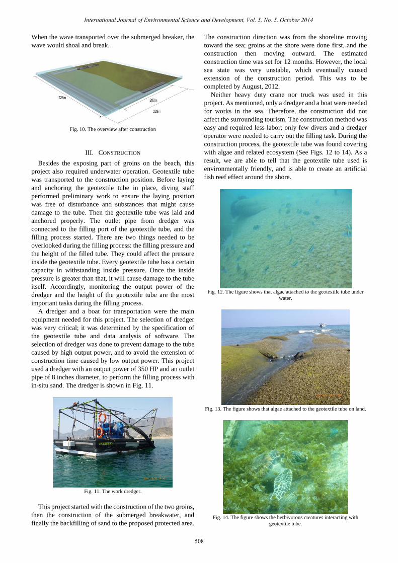
Neither heavy duty crane nor truck was used in this
project. As mentioned, only a dredger and a boat were needed
for works in the sea. Therefore, the construction did not
affect the surrounding tourism. The construction method was
easy and required less labor; only few divers and a dredger
operator were needed to carry out the filling task. During the
construction process, the geotextile tube was found covering
with algae and related ecosystem (See Figs. 12 to 14). As a
result, we are able to tell that the geotextile tube used is
environmentally friendly, and is able to create an artificial
fish reef effect around the shore.
Fig. 12. The figure shows that algae attached to the geotextile tube under
water.
Fig. 13. The figure shows that algae attached to the geotextile tube on land.
Fig. 14. The figure shows the herbivorous creatures interacting with
geotextile tube.
International Journal of Environmental Science and Development, Vol. 5, No. 5, October 2014
508

IV. CONCLUSION
Geotextile tube is easy in installation and no heavy duty
equipment is needed. Moreover, it has less impact to the
natural environment and landscape. Comparing with
conventional rubble groin construction method, geotextile
tube is easier and cost-efficient; rubbles are expensive in
local market, so it has an advantage in cost.
Geotextile tube has a good bonding to the natural
environment. Algae are able to grow on the surface rapidly
and create an ecosystem eventually. Comparing to rubble
structure, geotextile tube structure is a more natural-like
structure that is able to merge to the natural landscape; it
functions like a groin and submerged breakwater without a
clear man-made impression. This proves that the application
of geotextile tube is one of the innovative methods that can
replace the conventional method.
REFERENCES
[1] Coastal Engineering Manual, U.S. Army Corps of Engineers, Coastal
Engineering Research Center, Vicksburg, Miss. USA, 2004.
[2] K. W. Pilarczyk, Geosynthetics and Geosystems in Hydraulic and
Coastal Engineering, Rotterdam, The Netherlands: Taylor & Francis,
2000.
[3] E. Alvarez and B. Espinosa, “The role of the Geotextile Tubes in
coastal protection and beach restoration. The experience in Yucatan,
Mexico,” in Proc. First Pan American Geosynthetics Conference,
Cancun, Mexico, 2008.
[4] Geotextile Tube Structures Guidelines for Contract Specifications,
U.S. Army Corps of Engineers, Coastal Engineering Research Center,
Vicksburg, Miss. US, 2004.
[5] GeoCoPS(2.0): Supplemental Notes, ADAMA Engineering, Inc.,
Delaware, USA
[6] J. W. V. der Meer and K. W. Pilarczyk, “Stability of low-crested and
reef breakwaters,” Coastal Engineering '90, American Society of Civil
Engineers, USA, pp. 1375- 1388, 1990.
[7] J. W. V. der Meer and I. F. R. Daemen, “Stability and wave
transmission at low-crested rubbld-mound structures,” Journal of
Waterway, Port, Coastal and Ocean Engineering, ASCE, vol. 1, pp.
1-19.
Andy Chien was born in Taichung, Taiwan on April
18, 1985. Chien received a bachelor’s degree in habor
and river engineering from the National Taiwan Ocean
University in Keelung, Taiwan in year 2007.
Such education background automatically
determined his military obligation service in the Navy
as a marine engineer. While serving in the Navy, he
visited different seas and ports with naval ships, and
learnt the different sea conditions and port designs.
Later, he joined ACE Geosynthetics in Taichung, Taiwan in 2009; he is
currently holding the position of marine engineer. He has devoted himself to
the expertise field of geosynthetic application in marine and hydraulic
engineering, focusing on studies of geotextile tubes application, grout-filled
mattress, and geotextile property in marine environment.
Felix Tseng was born in Taichung, Taiwan. Tseng
received a master’s degree in habor and river
engineering from the National Sun Yat-sen University
in Kaohsiung, Taiwan in year 2005.
He engaged marine engineering research from the
university until present, he involved in a number of
cases of pre-construction design, and had six years of
construction experience to work in geotextile tube.
Tseng joined ACE Geosynthetics in 2007; he is
currently holding the position of marine chief engineer. He has devoted
himself to the expertise field of geosynthetic application in marine and
hydraulic engineering, focusing on geotextile tube, geotextile container
which applied in marine environment.
Shelly Wu was born in Taipei, Taiwan. She earned her
master’s degree in civil engineering from National
Chiao Tung University, Hsinchu City, Taiwan in 2007.
She assisted several geosynthetics research projects
during her study. With the passion for geosynthetics,
she joined ACE Geosynthetics in 2008. She travels
different countries and shares her knowledge of
geosynthetics in civil and marine engineering during
her working period. Currently she holds the position of
technical staff engineer and devotes herself to the expertise field of
geosynthetics application in various engineering.
Amy Tang has enthusiastically devoted herself to the
geosynthetic materials industry for more than a decade
and is specialized in the civil engineering. Amy
worked for the contractor and consultant company as
the supervisor and the designer for years, is a practiced
civil engineer in the scope of the structure design and
installation of reinforced retaining walls and analysis
of failures.
She currently is the technical manager of ACE Geosynthetics.
International Journal of Environmental Science and Development, Vol. 5, No. 5, October 2014
509