Embed Size (px)
Citation preview
________________________________________________
3213 Eastlake Avenue East, Suite B
Seattle, WA 98102
T. (206) 262-0370
F. (206) 262-0374
Geotechnical & Earthquake
Engineering Consultants
July 8, 2020
PanGEO Project No. 20-173
Mr. Michael Zhang
LA Ballard LLC
P.O. Box 572
Medina, WA 98039
Subject: Geotechnical Report
Proposed Development
4028 Midvale Avenue North, Seattle, Washington
Dear Mr. Zhang:
As requested, PanGEO, Inc. completed a geotechnical report for the proposed development
at 4028 Midvale Avenue North in Seattle, Washington. In preparing this report, we
completed two test borings at the site and conducted our engineering analyses. In
summary, our test borings encountered up to about 14 feet of loose fill and medium dense
recessional outwash overlying dense to very dense Vashon till. For the proposed basement,
foundation support likely can be provided using conventional footings bearing on
undisturbed competent native soils, or on properly compacted structural fill placed on the
competent native soils. Because the depth of bearing soil is more than ten feet below
existing grade in the west portion of the site, at-grade portion of the building can be
supported on pin piles in lieu of over-excavation. Excavation shoring will likely be needed
to limit the basement excavation to within the property limits.
We appreciate the opportunity to be of service. Should you have any questions, please do
not hesitate to call.
Sincerely,
Johnny C. Chen, P.E.
Project Geotechnical Engineer

20-173 4028 Midvale Ave N Rpt PanGEO, Inc.
TABLE OF CONTENTS
Section Page
1.0 GENERAL .................................................................................................................1 2.0 SITE AND PROJECT DESCRIPTION .....................................................................1 3.0 SUBSURFACE EXPLORATIONS ...........................................................................2
3.1 SITE GEOLOGY ................................................................................................2 3.2 TEST BORINGS ................................................................................................2 3.3 SOIL CONDITIONS............................................................................................3 3.4 GROUNDWATER ..............................................................................................3
4.0 GEOTECHNICAL RECOMMENDATIONS ...........................................................4 4.1 SEISMIC DESIGN PARAMETERS ........................................................................4 4.2 BUILDING FOUNDATIONS ................................................................................5
4.2.1 Conventional Footings (Basement Level) .......................................5
4.2.2 Pin Piles (At-grade Level) ..............................................................6 4.3 FLOORS SLABS ................................................................................................9 4.4 RETAINING WALL DESIGN PARAMETERS ........................................................10
5.0 TEMPORARY EXCAVATIONS AND SHORING ..................................................12 5.1 TEMPORARY EXCAVATION SLOPES .................................................................12 5.2 TEMPORARY SHORING ....................................................................................13 5.3 SOLDIER PILE WALL .......................................................................................13
5.3.1 Wall Design Parameters .................................................................13 5.3.2 Lagging ...........................................................................................13
5.4 BASELINE SURVEY AND MONITORING ............................................................14 6.0 EARTHWORK CONSIDERATIONS .......................................................................14
6.1 STRUCTURAL FILL AND COMPACTION .............................................................14 6.2 MATERIAL REUSE ...........................................................................................15 6.3 WET WEATHER CONSTRUCTION .....................................................................15 6.4 EROSION CONSIDERATIONS .............................................................................16
7.0 ADDITIONAL SERVICES .......................................................................................16
8.0 CLOSURE .................................................................................................................17 9.0 REFERENCES ...........................................................................................................19
ATTACHMENTS:
Figure 1 Vicinity Map
Figure 2 Site and Exploration Plan
Figure 3 Design Lateral Earth Pressures: Cantilevered Soldier Pile Shoring
Appendix A Summary Boring Logs
Figure A-1 Terms and Symbols for Boring and Test Pit Logs
Figure A-2 Log of Test Boring PG-1
Figure A-3 Log of Test Boring PG-2

20-173 4028 Midvale Ave N Rpt Page 1 PanGEO, Inc.
GEOTECHNICAL REPORT
PROPOSED DEVELOPMENT
4028 MIDVALE AVENUE NORTH
SEATTLE, WASHINGTON
1.0 GENERAL
As requested, PanGEO, Inc. is pleased to present this geotechnical report for the proposed
development in Seattle, Washington. This study was performed in general accordance with
our mutually agreed scope of services outlined in our proposal dated May 8, 2020. Our
scope of services included reviewing readily available geologic and geotechnical data,
drilling two test borings, conducting a site reconnaissance, and developing the conclusions
and recommendations presented in this report.
2.0 SITE AND PROJECT DESCRIPTION
The subject site is located at 4028 Midvale Avenue North in Seattle, Washington. The site
location is approximately as shown on Figure 1, Vicinity Map. The site is rectangular in
shape and measures approximately 40 feet in the north-south direction and about 100 feet
in the east-west direction. It is bordered by Midvale Avenue North to the west, and by
residences to the other three sides. The layout of the site is shown on Figure 2, Site and
Exploration Plan.
The site grade generally descends from west to east with a vertical topographic relief of
about six feet. A two-story single-family residence with a daylight basement currently
occupies the approximately middle portion of the site. A concrete retaining wall up to three
feet in height is located along the east portion of the north property line to retain the north
adjacent property. The areas surrounding the existing residence is covered with grass,
landscaping shrubs, and trees.
We understand that you plan to remove the existing residence and construct a 12-unit
apartment building at the site. The layout of the proposed development is indicated on the
attached Figure 2. Based on the current design drawings, the proposed building will be a
three-story wood frame structure with a one-level basement. The proposed basement floor
will be at about Elevation 130 feet. Thus, temporary excavation up to 15 feet deep may be
needed for the basement construction. With current side setbacks from the property lines,
we anticipate that temporary shoring will be likely needed to support the excavation along
the north and south property lines.
Geotechnical Report: Proposed Development
4028 Midvale Avenue N, Seattle, WA
July 8, 2020
20-173 4028 Midvale Ave N Rpt Page 2 PanGEO, Inc.
The conclusions and recommendations in this report are based on our understanding of the
proposed development, which is in turn based on the project information provided. If the
above project description is incorrect, or the project information changes, we should be
consulted to review the recommendations contained in this study and make modifications,
if needed. In any case PanGEO should be retained to provide a review of the final design
to confirm that our geotechnical recommendations have been correctly interpreted and
adequately implemented in the construction documents.
3.0 SUBSURFACE EXPLORATIONS
3.1 SITE GEOLOGY
General geologic information for the site was developed based on review of The Geologic
Map of Seattle – A Progress Report (Troost, et. al. 2005). Based on our review, the project
site is underlain by Vashon Till – Geologic Map Unit Qvt. Vashon till consists of an
unsorted deposit (diamict) of clay, silt, sand and gravel that has been glacially transported
and deposited. This geologic unit has been glacially overridden and is typically dense to
very dense.
3.2 Test Borings
Two borings (PG-1 and PG-2) were drilled at the site on May 21, 2020, using an Acker
Soil Mechanic, limited access drill rig operated by CN Drilling, Inc. under subcontract to
PanGEO. The borings were logged by a geologist from PanGEO. The borings were drilled
to a maximum depth of about 21 feet below existing grade. The approximate boring
locations were located in the field by measuring from property corners and site features
and are shown on Figure 2.
Standard Penetration Tests (SPT) were performed in the borings at 2½- and 5-foot depth
intervals using a standard, 2-inch diameter split-spoon sampler. The sampler was advanced
with a 140-pound drop hammer falling a distance of 30 inches for each strike, in general
accordance with ASTM D-1586, Standard Test Method for Penetration Test and Split
Barrel Sampling of Soils.
The soils were logged in general accordance with ASTM D-2487 Standard Practice for
Classification of Soils for Engineering Purposes and the system summarized on Figure A-
1, Terms and Symbols for Boring and Test Pit Logs. Summary boring logs are included as
Figures A-2 and A-3 in Appendix A.

Geotechnical Report: Proposed Development
4028 Midvale Avenue N, Seattle, WA
July 8, 2020
20-173 4028 Midvale Ave N Rpt Page 3 PanGEO, Inc.
3.3 SOIL CONDITIONS
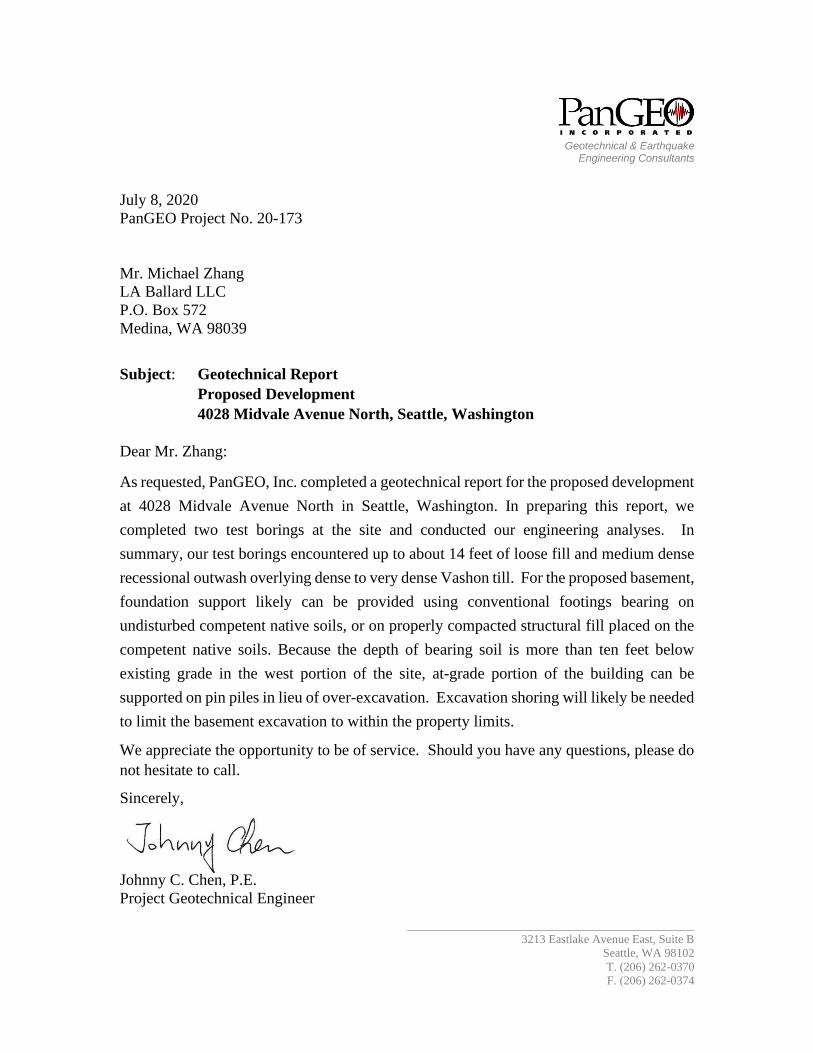
The soils observed in the borings generally consisted of loose fill overlying medium dense
recessional outwash overlying dense to very dense Vashon till. The following is a
summary description of the soils encountered in the borings at the site. Please refer to the
test boring logs (Figures A-2 and A-3) for a detailed description of the conditions
encountered at each boring location.
Fill – A surficial layer of fill was encountered in both test borings completed at the
site. The fill generally consisted of about five feet of loose, dark brown to brown,
silty fine sand with trace gravel and organics. We interpret this soil unit as fill.
Recessional Outwash – Below the fill, borings encountered a unit of medium
dense, interlayered sand and silty sand. This unit was about 9-foot thick in boring
PG-1 and about 4½-foot thick in boring PG-2. Based on the SPT N-values and soil
texture, we interpret this soil unit as recessional outwash deposits.
Vashon Till – Below recessional outwash, borings encountered a unit of dense to
very dense silty sand with trace gravel to the bottom of borings at about 21 and 15½
feet below existing grade in borings PG-1 and PG-2, respectively. This soil unit
appears to be consistent with the mapped Vashon till.
Our subsurface descriptions are based on the conditions encountered at the time of our
exploration. Soil conditions between our exploration locations may vary from those
encountered. The nature and extent of variations between our exploratory locations may
not become evident until construction. If variations do appear, PanGEO should be
requested to reevaluate the recommendations in this report and to modify or verify them in
writing prior to proceeding with earthwork and construction.
3.4 GROUNDWATER
Groundwater was observed in borings PG-1 and PG-2 at depths of about 12½ and 9 feet
below existing grade during drilling, respectively. The groundwater appeared to be perched
above the underlying dense till layer. It should be noted that groundwater levels will
fluctuate depending on the season, amount of rainfall, surface water runoff, and other
factors. Generally, the water level is higher and seepage rates are greater in the wetter,
winter months (typically October through May).

Geotechnical Report: Proposed Development
4028 Midvale Avenue N, Seattle, WA
July 8, 2020
20-173 4028 Midvale Ave N Rpt Page 4 PanGEO, Inc.
4.0 GEOTECHNICAL RECOMMENDATIONS
4.1 SEISMIC DESIGN PARAMETERS
The 2015 International Building Code (IBC) seismic design section provides a basis for
seismic design of structures. Table 1, below, provides seismic design parameters for the
site that are in conformance with the 2015 editions of IBC, which specifies a design
earthquake having a 2% probability of occurrence in 50 years (return interval of 2,475
years), and the 2008 USGS seismic hazard maps.
Table 1 – Seismic Design Parameters
The spectral response accelerations were obtained from OSHPD Seismic Design Maps
website (https://seismicmaps.org) based on the project address.
Liquefaction Potential: Liquefaction is a process that can occur when soils lose shear
strength for short periods of time during a seismic event. Ground shaking of sufficient
strength and duration results in the loss of grain-to-grain contact and an increase in pore
water pressure, causing the soil to behave as a fluid. Soils with a potential for liquefaction
are typically cohesionless, predominately silt and sand sized, must be loose, and be below
the groundwater table. With the planned excavation, the proposed basement footprint will
be predominantly underlain by dense to very dense Vashon till. The at-grade (west) portion
of the building will be supported by pin piles. Based on these conditions, in our opinion
the liquefaction potential of the site is negligible and design considerations related to soil
liquefaction are not necessary for this project.
Site
Class
Spectral
Acceleration
at 0.2 sec. [g]
SS
Spectral
Acceleration
at 1.0 sec. [g]
S1
Site Coefficients Design Spectral
Response Parameters
Fa Fv SDS SD1
D 1.296 0.503 1.00 1.50 0.864 0.503

Geotechnical Report: Proposed Development
4028 Midvale Avenue N, Seattle, WA
July 8, 2020
20-173 4028 Midvale Ave N Rpt Page 5 PanGEO, Inc.
4.2 BUILDING FOUNDATIONS
4.2.1 Conventional Footings (Basement Level)
Based on the subsurface conditions encountered at the site and our understanding of the
planned development, it is our opinion the proposed basement can be supported on
conventional footings. The footings should bear on the undisturbed dense to very dense
native soils that are expected to be encountered at or near the footing subgrade elevations.
Footings may also be founded on properly compacted structural fill placed on competent
native soils.
Exterior foundation elements should be placed at a minimum depth of 18 inches below
final exterior grade. Interior spread foundations should be placed at a minimum depth of
12 inches below the top of concrete slabs.
We recommend a maximum allowable soil bearing pressure of 4,000 pounds per square
foot (psf) be used for sizing foundation elements bear on the undisturbed dense native soils
or properly compacted structural fill. The recommended allowable soil bearing pressure is
for dead plus live loads. For allowable stress design, the recommended bearing pressure
may be increased by one-third for transient loading, such as wind or seismic forces.
Continuous and individual spread footings should have minimum widths of 18 and 24
inches, respectively.
Footings designed and constructed in accordance with the above recommendations should
experience total settlement of less than one inch and differential settlement of less than ½
inch. Most of the anticipated settlement should occur during construction as dead loads
are applied.
Lateral Resistance
Lateral loads on the structure may be resisted by passive earth pressure developed against
the embedded portion of the foundation system and by frictional resistance between the
bottom of the foundation and the supporting subgrade soils. For footings bearing on the
dense silty sand, a frictional coefficient of 0.35 may be used to evaluate sliding resistance
developed between the concrete and the subgrade soil. Passive soil resistance may be
calculated using an equivalent fluid weight of 320 pcf, assuming foundations are backfilled
with structural fill. The above values include a factor of safety of 1.5. Unless covered by

Geotechnical Report: Proposed Development
4028 Midvale Avenue N, Seattle, WA
July 8, 2020
20-173 4028 Midvale Ave N Rpt Page 6 PanGEO, Inc.
pavements or slabs, the passive resistance in the upper 12 inches of soil should be
neglected.
Perimeter Footing Drains
Footing drains should be installed around the perimeter of the buildings, at or just below
the invert of the footings. Under no circumstances should roof downspout drain lines be
connected to the footing drain systems. Roof downspouts must be separately tightlined to
appropriate discharge locations. Cleanouts should be installed at strategic locations to
allow for periodic maintenance of the footing drain and downspout tightline systems.
Footing Subgrade Preparation
All footing subgrade should be properly prepared and in a firm and unyielding condition
prior to setting forms and placing reinforcing steel. Any loose or softened soil should be
removed from the footing excavations. The adequacy of the footing subgrade soils should
be verified by a representative of PanGEO, prior to placing forms or rebar.
It should be noted that the native soils underlying the site is very moisture sensitive, and
can be easily disturbed when exposed to moisture and construction activities. Efforts
should be made to protect the exposed footing subgrade if the footings will be constructed
in wet weather conditions. This may include placing a few inches of lean-mix concrete on
the exposed footing subgrade to protect the subgrade.
4.2.2 Pin Piles (At-grade Level)
Based on the results of test borings, the west portion of the site is underlain approximately
five feet of very loose fill over nine feet of recessional outwash deposits. The depth of
bearing soil is estimated about 13 feet below existing grade. To reach the bearing soil,
minimum 13 feet of over-excavation will be needed for building foundations. As such, we
recommend the at-grade (west) portion of the proposed building be supported on pin piles
in lieu of over-excavation.
The pin piles may consist of 3- or 4-inch diameter, Schedule 40, galvanized, steel pipes.
Allowable axial compression capacities of 6 and 10 tons may be used for the 3- and 4-inch
diameter pin piles, respectively. Tensile capacity of the pin piles should be ignored.
Penetration resistance required to achieve the capacities will be determined based on the

Geotechnical Report: Proposed Development
4028 Midvale Avenue N, Seattle, WA
July 8, 2020
20-173 4028 Midvale Ave N Rpt Page 7 PanGEO, Inc.
hammer used as discussed in the following sections. Total and differential foundation
settlements are anticipated to be on the order of about ½ inch or less.
The required pile length in order to develop the recommended pile capacity is expected to
vary, depending on the depth of loose/soft soils below the at-grade building footprint. For
planning and cost estimating purposes, an average pile length of about 20 feet may be
assumed for the site. However, the actual pile lengths will be determined during
construction based on actual driving conditions, and may vary significantly from the
estimate. A minimum pile length of 15 feet should also be specified in the project plans.
Pile splices may be made with compression fitted sleeve pipe couplers (see Typical
Splicing Detail on Page 8). Splicing using welding of pipe joints should not be used, as
welds will typically be broken during driving.
Three- or four-inch diameter piles are typically installed using small (approximately 650
to 1,100 pound) hammers mounted to a small excavator. The criterion for driving refusal
is defined as the minimum amount of time (in seconds) required to achieve one inch of
penetration, and it varies with the size of hammer used for pile driving. For 3- or 4-inch
pin piles, the following is a summary of driving refusal criteria for different hammer sizes
that are commonly used:
Table 2 - Summary of Commonly-Accepted Driving Criteria for a 3- and
4-inch Diameter Pipe Piles with a 6- or 10-ton Allowable Axial
Compression Load
Hammer
Model
Hammer
Weight (lb) /
Blows per
minute
3-inch Pile Driving
Refusal Criteria
(seconds per inch of
penetration)
4-inch Pile Driving
Refusal Criteria
(seconds per inch of
penetration)
Hydraulic TB
225
650 /
550 - 1100 12 20
Hydraulic TB
325
850 /
550 - 1100 10 16
Hydraulic TB
425
1,100 /
550 - 1100 6 10
Please note that these refusal criteria were established empirically based on previous load
tests on 3- and 4-inch pin piles. Contractors may select a different hammer for driving

Geotechnical Report: Proposed Development
4028 Midvale Avenue N, Seattle, WA
July 8, 2020
20-173 4028 Midvale Ave N Rpt Page 8 PanGEO, Inc.
these piles, and propose a different driving criterion. In this case, it is the contractor’s
responsibility to demonstrate to the Engineer’s satisfaction that the design load can be
achieved based on their selected equipment and driving criteria.
The quality of a pin pile foundation is dependent in part on the experience and
professionalism of the installation company. Therefore, a qualified contractor with pin pile
driving experience on similar projects should be selected to install the piles. We
recommend that the following specifications be included on the foundation plan:
1. All piles shall consist of galvanized Schedule-40, ASTM A-53 Grade “A” pipe.
2. 3- and 4-inch pin piles shall be driven to refusal as shown in Table 2 of this
report.
3. Piles shall be driven in nominal sections and connected with compression fitted
sleeve couplers (see detail below – Courtesy of McDowell Pile King, Kent, WA).
4. 3% of piles up to 5 piles maximum should be load tested to verify the design
capacities. All load tests shall be performed in accordance with the procedure
outlined in ASTM D1143. The maximum test load shall be 2 times the design
load (e.g. 2 x 10 tons = 20 tons).
5. The geotechnical engineer of record or his/her representative shall provide full
time observation of pile installation and testing to verify the driving refusal
criteria.
Typical Splicing Detail

Geotechnical Report: Proposed Development
4028 Midvale Avenue N, Seattle, WA
July 8, 2020
20-173 4028 Midvale Ave N Rpt Page 9 PanGEO, Inc.
Lateral Forces - The capacity of vertical pin pipes to resist lateral loads is very limited and
should not be used in design. Therefore, lateral forces should be resisted by the passive
earth pressures acting against the pile caps and below-grade walls or from battered piles
(batter no steeper than 3(H):12(V)). Friction at the base of pile-supported concrete grade
beam should be ignored in the design calculations. Passive resistance values may be
determined using an equivalent fluid weight of 250 pounds per cubic foot (pcf). This value
includes a safety factor of about 1.5 assuming that properly compacted granular fill will be
placed adjacent to and surrounding the pile caps and grade beams.
Obstructions – Obstructions may be encountered within the fill soil. Where possible, the
obstructions should be removed to facilitate the pile driving. If obstructions cannot be
removed, the structural engineer of record should be notified to revise the pile layout to
accommodate moving the piles.
4.3 FLOORS SLABS
The floor slabs for the proposed building may be constructed using conventional concrete
slab-on-grade floor construction. The floor slab should be supported on competent native
soils or on structural fill paced on competent native soils. Any over-excavations, if needed,
should be backfilled with properly compacted structural fill.
For the at-grade portion supported on pin piles, a structural slab should be designed and
constructed for the floor slab. The subgrade of floor should be over-excavated a foot and
backfilled with structural fill.
Interior concrete slab-on-grade floors should be underlain by a capillary break consisting
of at least of 4 inches of pea gravel or compacted ¾-inch, clean crushed rock (less than 3
percent fines). The capillary break material should meet the gradational requirements
provided in Table 3, below.
Table 3 – Capillary Break Gradation
Sieve Size Percent Passing
¾-inch 100
No. 4 0 – 10
No. 100 0 – 5
No. 200 0 – 3

Geotechnical Report: Proposed Development
4028 Midvale Avenue N, Seattle, WA
July 8, 2020
20-173 4028 Midvale Ave N Rpt Page 10 PanGEO, Inc.
The capillary break should be placed on the subgrade that has been compacted to a dense
and unyielding condition.
A minimum 10-mil polyethylene vapor barrier should also be placed directly below the
slab. Construction joints should be incorporated into the floor slab to control cracking.
4.4 RETAINING WALL DESIGN PARAMETERS
Retaining and basement walls should be designed to resist the lateral earth pressures
exerted by the soils behind the wall. Proper drainage provisions should also be provided
behind the walls to intercept and remove groundwater that may be present behind the wall.
Our geotechnical recommendations for the design and construction of the retaining wall
are presented below.
Lateral Earth Pressures
Cantilever walls should be designed for an equivalent fluid pressure of 35 pcf for a level
backfill condition behind the walls assuming the walls are free to rotate. If the walls are
restrained at the top from free movement, such as basement walls with a floor diaphragm,
an equivalent fluid pressure of 45 pcf should be used for a level backfill condition behind
the walls. Walls with a maximum 2H:1V backslope should be designed for an active and
at rest earth pressure of 45 and 55 pcf, respectively. Permanent walls should be designed
for an additional uniform lateral pressure of 7H psf for seismic loading, where H
corresponds to the buried depth of the wall.
The recommended lateral pressures assume the backfill behind the walls consists of a free
draining and properly compacted fill with adequate drainage provisions.
Surcharge
Surcharge loads, where present, should also be included in the design of retaining walls.
We recommend a lateral load coefficient of 0.3 be used to compute the lateral pressure on
the wall face resulting from surcharge loads located within a horizontal distance of one-
half the wall height.
Lateral Resistance
Lateral forces from seismic loading and unbalanced lateral earth pressures may be resisted
by a combination of passive earth pressures acting against the embedded portions of the

Geotechnical Report: Proposed Development
4028 Midvale Avenue N, Seattle, WA
July 8, 2020
20-173 4028 Midvale Ave N Rpt Page 11 PanGEO, Inc.
foundations and by friction acting on the base of the wall foundation. Passive resistance
values may be determined using an equivalent fluid weight of 320 pcf. This value includes
a factor of safety of 1.5, assuming the footing is backfilled with structural fill. A friction
coefficient of 0.35 may be used to determine the frictional resistance at the base of the
footings. The coefficient includes a factor of safety of 1.5.
Wall Drainage
Provisions for wall drainage should consist of a 4-inch diameter perforated drainpipe
placed behind and at the base of the wall footings, embedded in 12 to 18 inches of clean
crushed rock or pea gravel wrapped with a layer of filter fabric. A minimum 18-inch wide
zone of free draining granular soils (i.e. pea gravel or washed rock) is recommended to be
placed adjacent to the wall for the full height of the wall. Alternatively, a composite
drainage material, such as Miradrain 6000, may be used in lieu of the clean crushed rock
or pea gravel. The drainpipe at the base of the wall should be graded to direct water to a
suitable outlet.
Wall Backfill
Retaining wall backfill should consist of free draining granular material. The site soils are
relatively silty and would not meet the requirements for wall backfill. We recommend
importing a free draining granular material, such as Seattle Type 17 or a soil meeting the
requirements of Gravel Borrow as defined in Section 9-03.14(1) of the WSDOT Standard
Specifications for Road, Bridge, and Municipal Construction (WSDOT, 2020). In areas
where space is limited between the wall and the face of excavation, pea gravel may be used
as backfill without compaction.
Wall backfill should be properly moisture conditioned, placed in loose, horizontal lifts less
than 12 inches in thickness, and compacted to a dense and unyielding condition. If density
tests will be performed, the test results should show at least 95 percent of the maximum
dry density, as determined using test method ASTM D-1557 (Modified Proctor). Within
5 feet of the wall, the backfill should be compacted with hand-operated equipment to at
least 90 percent of the maximum dry density.

Geotechnical Report: Proposed Development
4028 Midvale Avenue N, Seattle, WA
July 8, 2020
20-173 4028 Midvale Ave N Rpt Page 12 PanGEO, Inc.
4.5 PERMANENT CUT AND FILL SLOPES
Based on the anticipated soil that will be exposed in the planned excavation, we
recommend permanent cut and fill slopes be constructed no steeper than 2H:1V
(Horizontal:Vertical)
5.0 TEMPORARY EXCAVATIONS AND SHORING
As currently planned, the excavation for the proposed basement and building foundations
may be as deep as 15 feet. Within the depth of the excavation, we anticipate the excavation
to encounter fill overlying medium dense to very dense native soils. All temporary
excavations should be performed in accordance with Part N of WAC (Washington
Administrative Code) 296-155. The contractor is responsible for maintaining safe
excavation slopes and/or shoring.
5.1 TEMPORARY EXCAVATION SLOPES
All temporary excavations deeper than a total height of 4 feet should be sloped or shored.
Where space is available, it is our opinion that unsupported open cut excavation is feasible
at the site. Based on the soil conditions at the site, for planning purposes, it is our opinion
that temporary excavations for the proposed building construction may be sloped as steep
as 1H:1V (Horizontal: Vertical). Where space is limited, the use of L-shaped footings may
be considered to reduce the lateral extent of the proposed excavation.
Based on our current understanding of the building layout and finished floor elevation,
unsupported open cut is likely feasible on the west and east sides of excavation. If sufficient
space is not available for an unsupported open cut and construction easements cannot be
obtained from the neighboring property owners, excavation shoring will be required for the
basement wall construction.
The temporary excavations and cut slopes should be re-evaluated in the field during
construction based on actual observed soil conditions, and may need to be flattened in the
wet reasons and should be covered with plastic sheets. The cut slopes should be covered
with plastic sheets in the raining season. We also recommend that heavy construction
equipment, building materials, excavated soil, and vehicular traffic should not be allowed
within a distance equal to 1/3 the slope height from the top of any excavation.

Geotechnical Report: Proposed Development
4028 Midvale Avenue N, Seattle, WA
July 8, 2020
20-173 4028 Midvale Ave N Rpt Page 13 PanGEO, Inc.
5.2 TEMPORARY SHORING
As currently planned, an excavation up to about 15 feet deep may be needed for the
basement excavation. Unless an excavation easement can be obtained from the neighboring
property owners, a structural shoring wall will be needed along the north and south property
lines. In our opinion, a soldier pile wall with timber lagging is likely the most appropriate
shoring option.
The shoring system should be designed to provide adequate protection for the workers,
adjacent structures, utilities, and other facilities. Excavations should be performed in
accordance with the current requirements of WISHA. Construction should proceed as
rapidly as feasible, to limit the time temporary excavations are open.
5.3 SOLDIER PILE WALL
Soldier pile wall consists of vertical steel beams, typically spaced from 6 to 8 feet apart
along the proposed excavation alignment, spanned by timber lagging. Prior to the start of
excavation, the steel beams are installed in holes drilled to a design depth and then
backfilled with lean mix or structural concrete. As the excavation proceeds downward and
the steel piles are subsequently exposed, timber lagging is installed between the piles to
further stabilize the walls of the excavation. Tiebacks are typically used for wall heights
greater than about 15 feet to achieve a more economical design.
5.3.1 Wall Design Parameters
We recommend that the earth pressures depicted on Figure 3 may be used for the temporary
shoring design.
The vertical capacity of the soldier piles should be determined using an allowable skin
friction value of 0.5 ksf for the portion of the pile below the neighbor’s grade, and an
allowable end soil bearing capacity value of 10 ksf.
5.3.2 Lagging
Lagging design recommendations are presented on Figure 3. We recommend voids behind
the lagging be backfilled with either Control Density Fill (CDF), sand, or approved
alternative materials.

Geotechnical Report: Proposed Development
4028 Midvale Avenue N, Seattle, WA
July 8, 2020
20-173 4028 Midvale Ave N Rpt Page 14 PanGEO, Inc.
5.4 BASELINE SURVEY AND MONITORING
Ground movements will occur as a result of excavation activities. As such, ground surface
elevations of the adjacent properties and city streets should be documented prior to
commencing earthwork to provide baseline data. At a minimum, optical survey points
should be established at the following locations:
• The top of every other soldier pile should be monitoring twice a week during
excavation for lagging installation. Based on the monitoring results, the
monitoring frequency may be reduced to once a week after the foundation is
completed.
• Adjacent structures or retaining walls located within about 20 feet of the planned
shoring.
The monitoring program should include monitoring for changes in both the horizontal (x
and y directions) and vertical deformations. The monitoring should be performed by the
project surveyor, and the results should be promptly submitted to PanGEO for review. The
results of the monitoring will allow the design team to confirm design parameters, and for
the contractor to make adjustments if necessary.
We also recommend the existing conditions along the public right of way and the adjacent
private properties be photo-documented prior to commencing earthwork at the site.
6.0 EARTHWORK CONSIDERATIONS
6.1 STRUCTURAL FILL AND COMPACTION
Structural fill, if needed, should consist of City of Seattle Type 17, WSDOT Section 9-
03.9(3) Crushed Surfacing Base Course (WSDOT 2020), or an approved equivalent.
Structural fill should be properly moisture conditioned, placed in loose, horizontal lifts less
than 12 inches in thickness, and compacted to a dense and unyielding condition. The
adequacy of compaction should be verified by a PanGEO representative. Alternatively, a
minimum 95 percent maximum density as determined using ASTM D-1557 (Modified
Proctor) maybe used to determine the adequacy of the compacted fill.
The procedure to achieve proper density of a compacted fill depends on the size and type
of compaction equipment, the number of passes, thickness of the lifts being compacted,
and certain soil properties. If the excavation to be backfilled is constricted and limits the

Geotechnical Report: Proposed Development
4028 Midvale Avenue N, Seattle, WA
July 8, 2020
20-173 4028 Midvale Ave N Rpt Page 15 PanGEO, Inc.
use of heavy equipment, smaller equipment can be used, but the lift thickness will need to
be reduced to achieve the required relative compaction.
Generally, loosely compacted soils are a result of poor construction technique or improper
moisture content. Soils with high fines contents are particularly susceptible to becoming
too wet and coarse-grained materials easily become too dry, for proper compaction. Soils
with a moisture content too high for adequate compaction should be dried as necessary, or
moisture conditioned by mixing with drier materials, or other methods.
6.2 MATERIAL REUSE
The existing fill and native soils underlying the site primarily consist of silty sand with
trace gravel, are moisture sensitive, and will become disturbed and soft when exposed to
inclement weather conditions. We do not recommend reusing the native soils as structural
fill. If it is planned to use the native soil in non-structural areas, the excavated soil should
be stockpiled and protected with plastic sheeting to prevent it from becoming saturated by
precipitation or runoff.
6.3 WET WEATHER CONSTRUCTION
General recommendations relative to earthwork performed in wet weather or in wet
conditions are presented below. The following procedures are best management practices
recommended for use in wet weather construction:
• Earthwork should be performed in small areas to minimize subgrade exposure
to wet weather. Excavation or the removal of unsuitable soil should be followed
promptly by the placement and compaction of clean structural fill. The size and
type of construction equipment used may have to be limited to prevent soil
disturbance.
• During wet weather, the allowable fines content of the structural fill should be
reduced to no more than 5 percent by weight based on the portion passing the
0.75-inch sieve. The fines should be non-plastic.
• The ground surface within the construction area should be graded to promote
run-off of surface water and to prevent the ponding of water.
• Geotextile silt fences should be installed at strategic locations around the site to
control erosion and the movement of soil.

Geotechnical Report: Proposed Development
4028 Midvale Avenue N, Seattle, WA
July 8, 2020
20-173 4028 Midvale Ave N Rpt Page 16 PanGEO, Inc.
• Excavation slopes and soils stockpiled on site should be covered with plastic
sheeting.
6.4 EROSION CONSIDERATIONS
Surface runoff can be controlled during construction by careful grading practices.
Typically, this includes the construction of shallow, upgrade perimeter ditches or low
earthen berms in conjunction with silt fences to collect runoff and prevent water from
entering excavations or to prevent runoff from the construction area leaving the immediate
work site. Temporary erosion control may require the use of hay bales on the downhill
side of the project to prevent water from leaving the site and potential storm water detention
to trap sand and silt before the water is discharged to a suitable outlet. All collected water
should be directed under control to a positive and permanent discharge system.
Permanent control of surface water should be incorporated in the final grading design.
Adequate surface gradients and drainage systems should be incorporated into the design
such that surface runoff is collected and directed away from the structure to a suitable
outlet. Potential issues associated with erosion may also be reduced by establishing
vegetation within disturbed areas immediately following grading operations.
7.0 ADDITIONAL SERVICES
We anticipate the City of Seattle will require a plan review and geotechnical special
inspections to confirm that our recommendations are properly incorporated into the design
and construction of the proposed development. Specifically, we anticipate that the
following construction support services may be needed:
• Review final project plans and specifications;
• Verify implementation of erosion control measures;
• Observe installation of excavation shoring system;
• Observe the stability of any open cut slopes;
• Review optical survey data provided by others to evaluate the performance of
the shoring system;
• Verify adequacy of footing and slab subgrades;
• Confirm the adequacy of the compaction of structural backfill;

Geotechnical Report: Proposed Development
4028 Midvale Avenue N, Seattle, WA
July 8, 2020
20-173 4028 Midvale Ave N Rpt Page 17 PanGEO, Inc.
• Observe installation of subsurface drainage provisions, and;
• Other consultation as may be required during construction.
Modifications to our recommendations presented in this report may be necessary, based on
the actual conditions encountered during construction.
8.0 CLOSURE
We have prepared this report for LA Ballard LLC and the project design team.
Recommendations contained in this report are based on a site reconnaissance, a subsurface
exploration program, review of pertinent subsurface information, and our understanding of
the project. The study was performed using a mutually agreed-upon scope of services.
Variations in soil conditions may exist between the locations of the explorations and the
actual conditions underlying the site. The nature and extent of soil variations may not be
evident until construction occurs. If any soil conditions are encountered at the site that are
different from those described in this report, we should be notified immediately to review
the applicability of our recommendations. Additionally, we should also be notified to
review the applicability of our recommendations if there are any changes in the project
scope.
The scope of our work does not include services related to construction safety precautions.
Our recommendations are not intended to direct the contractors’ methods, techniques,
sequences or procedures, except as specifically described in our report for consideration in
design. Additionally, the scope of our services specifically excludes the assessment of
environmental characteristics, particularly those involving hazardous substances. We are
not mold consultants nor are our recommendations to be interpreted as being preventative
of mold development. A mold specialist should be consulted for all mold-related issues.
This report has been prepared for planning and design purposes for specific application to
the proposed project in accordance with the generally accepted standards of local practice
at the time this report was written. No warranty, express or implied, is made.
This report may be used only by the client and for the purposes stated, within a reasonable
time from its issuance. Land use, site conditions (both off and on-site), or other factors
including advances in our understanding of applied science, may change over time and
could materially affect our findings. Therefore, this report should not be relied upon after
24 months from its issuance. PanGEO should be notified if the project is delayed by more

Geotechnical Report: Proposed Development
4028 Midvale Avenue N, Seattle, WA
July 8, 2020
20-173 4028 Midvale Ave N Rpt Page 18 PanGEO, Inc.
than 24 months from the date of this report so that we may review the applicability of our
conclusions considering the time lapse.
It is the client’s responsibility to see that all parties to this project, including the designer,
contractor, subcontractors, etc., are made aware of this report in its entirety. The use of
information contained in this report for bidding purposes should be done at the contractor’s
option and risk. Any party other than the client who wishes to use this report shall notify
PanGEO of such intended use and for permission to copy this report. Based on the intended
use of the report, PanGEO may require that additional work be performed and that an
updated report be reissued. Noncompliance with any of these requirements will release
PanGEO from any liability resulting from the use this report.
Sincerely,
PanGEO, Inc.
07/08/2020
Chien-Lin (Johnny) Chen, P.E.
Project Geotechnical Engineer

Geotechnical Report: Proposed Development
4028 Midvale Avenue N, Seattle, WA
July 8, 2020
20-173 4028 Midvale Ave N Rpt Page 19 PanGEO, Inc.
9.0 REFERENCES
ASTM International (ASTM), 2020, Annual book of standards, Section 04.08 Soil and
Rock (I): D420-D5876: West Conshohocken, Pennsylvania.
City of Seattle, 2020, Standard Specifications for Road, Bridges, and Municipal
Construction.
International Code Council, 2015, International Building Code (IBC), 2015.
Troost, K.G., Booth, D. B., Wisher, A. P., Shimmel, S. A., 2005, The Geologic Map of
Seattle-A Progress Report, Seattle, Washington – U. S. Geological Survey Open File
Report 2005-1252, scale 1:24,000.
United States Geological Survey, Earthquake Hazards Program, Interpolated
Probabalisitic Ground Motion for the Conterminous 48 States by Latitude and
Longitude, 2008 Data, accessed via:
http://earthquake.usgs.gov/designmaps/us/application.php
Washington State Department of Transportation (WSDOT), 2020, Standard
Specifications for Road, Bridge and Municipal Construction, M 41-10.
Washington Administrative Code (WAC), 2016, Chapter 296-155 - Safety Standards for
Construction Work, Part N - Excavation, Trenching, and Shoring, Olympia,
Washington.

20-173 1
VICINITY MAP
Figure No.Project No.
Reference: Google Terrain Maps
Proposed Development4028 Midvale Avenue N
Seattle, Washington
Project Site
Not to Scale

Project No. Figure No.
SITE AND EXPLORATION PLAN
20-173 2
Approx. Test Boring Location(10') (Depth to Bearing Soils, ft)
Legend: Note: Base map modified from Topographic & Boundary Survey by Terrane dated 4/22/2019
Proposed Development4028 Midvale Avenue N
Seattle, Washington
Approx. Scale1" = 20'
Alle
y PG-2(10')PG-1
(13')
Approx. BasementFootprint
Approx. BuildingFootprint

Project No. Figure No.
Fig 3 - Cantilever Shoring.grf w/ [file.jpg] 7/8/20 (4:50:06) BW
Base of Excavation
Soldier Pile Wall withTimber Lagging
H
Passive PressureActive Pressure
Footing/SurfaceSurcharge = q
320 pcf1
45 pcf (1H:1V backslope)35 pcf (level backslope)
1
Bf X
1
1 1H:1V Temporary Cut(if applicable)
Level Backslope
X
Apply only to above bottom of excavation
0.4(1 - X/H) q
Footing/Surface Surcharge:
Notes:1. Minumum embedment should be at least 10 feet below bottom of excavation.2. A factor of safety of 1.5 has been applied to the recommended passive pressure values. No factor of safety has been applied to the recommended active earth pressure values.3. Active pressures should be applied over the full width of the pile spacing above the base of the excavation, and over one pile diameter below the base of the excavation.4. Surcharge pressures should be applied over the entire length of the loaded area.5. Passive pressure should be applied to two times the diameter of the soldier piles.6. Use 50% of the active and surcharge pressures for lagging design with soldier piles spaced at 8' or less.7. Refer to report text for additional discussions.
Proposed Development4028 Midvale Avenue N
Seattle, Washington
DESIGN LATERAL EARTHPRESSURES: CANTILEVERED
SOLDIER PILE SHORING
20-173 3
Limit to above botttom ofExcavation.15 feet (max)
75 psfStreet Traffic Surcharge
(where applicable)
X
3Bf

APPENDIX A
SUMMARY BORING LOGS

MOISTURE CONTENT
2-inch OD Split Spoon, SPT(140-lb. hammer, 30" drop)
3.25-inch OD Spilt Spoon(300-lb hammer, 30" drop)
Non-standard penetrationtest (see boring log for details)
Thin wall (Shelby) tube
Grab
Rock core
Vane Shear
Dusty, dry to the touch
Damp but no visible water
Visible free water
Terms and Symbols forBoring and Test Pit Logs
Density
SILT / CLAY
GRAVEL (<5% fines)
GRAVEL (>12% fines)
SAND (<5% fines)
SAND (>12% fines)
Liquid Limit < 50
Liquid Limit > 50
Breaks along defined planesFracture planes that are polished or glossyAngular soil lumps that resist breakdownSoil that is broken and mixedLess than one per footMore than one per footAngle between bedding plane and a planenormal to core axis
Very LooseLooseMed. DenseDenseVery Dense
SPTN-values
Approx. Undrained ShearStrength (psf)
<44 to 10
10 to 3030 to 50
>50
<22 to 44 to 88 to 15
15 to 30>30
Units of material distinguished by color and/orcomposition from material units above and belowLayers of soil typically 0.05 to 1mm thick, max. 1 cmLayer of soil that pinches out laterallyAlternating layers of differing soil materialErratic, discontinuous deposit of limited extentSoil with uniform color and composition throughout
Approx. RelativeDensity (%)
Gravel
Layered:
Laminated:Lens:
Interlayered:Pocket:
Homogeneous:
Highly Organic Soils
#4 to #10 sieve (4.5 to 2.0 mm)#10 to #40 sieve (2.0 to 0.42 mm)#40 to #200 sieve (0.42 to 0.074 mm)0.074 to 0.002 mm<0.002 mm
UNIFIED SOIL CLASSIFICATION SYSTEMMAJOR DIVISIONS GROUP DESCRIPTIONS
Notes:
MONITORING WELL
SPTN-values
<1515 - 3535 - 6565 - 8585 - 100
GW
GP
GM
GC
SW
SP
SM
SC
ML
CL
OL
MH
CH
OH
PT
TEST SYMBOLS
50%or more passing #200 sieve
Groundwater Level attime of drilling (ATD)
Static Groundwater Level
Cement / Concrete Seal
Bentonite grout / seal
Silica sand backfill
Slotted tip
Slough
<250250 - 500500 - 1000
1000 - 20002000 - 4000
>4000
RELATIVE DENSITY / CONSISTENCY
Fissured:Slickensided:
Blocky:Disrupted:Scattered:
Numerous:BCN:
COMPONENT DEFINITIONS
Dry
Moist
Wet
1. Soil exploration logs contain material descriptions based on visual observation and field tests using a systemmodified from the Uniform Soil Classification System (USCS). Where necessary laboratory tests have beenconducted (as noted in the "Other Tests" column), unit descriptions may include a classification. Please refer to thediscussions in the report text for a more complete description of the subsurface conditions.
2. The graphic symbols given above are not inclusive of all symbols that may appear on the borehole logs.Other symbols may be used where field observations indicated mixed soil constituents or dual constituent materials.
COMPONENT SIZE / SIEVE RANGE COMPONENT SIZE / SIEVE RANGE
SYMBOLSSample/In Situ test types and intervals
Silt and Clay
Consistency
SAND / GRAVEL
Very SoftSoftMed. StiffStiffVery StiffHard
Phone: 206.262.0370
Bottom of BoringBoulder:Cobbles:Gravel
Coarse Gravel:Fine Gravel:
SandCoarse Sand:Medium Sand:
Fine Sand:SiltClay
> 12 inches3 to 12 inches
3 to 3/4 inches3/4 inches to #4 sieve
Figure A-1
Atterberg Limit TestCompaction TestsConsolidationDry DensityDirect ShearFines ContentGrain SizePermeabilityPocket PenetrometerR-valueSpecific GravityTorvaneTriaxial CompressionUnconfined Compression
Sand50% or more of the coarsefraction passing the #4 sieve.Use dual symbols (eg. SP-SM)for 5% to 12% fines.
for In Situ and Laboratory Testslisted in "Other Tests" column.
50% or more of the coarsefraction retained on the #4sieve. Use dual symbols (eg.GP-GM) for 5% to 12% fines.
DESCRIPTIONS OF SOIL STRUCTURES
Well-graded GRAVEL
Poorly-graded GRAVEL
Silty GRAVEL
Clayey GRAVEL
Well-graded SAND
Poorly-graded SAND
Silty SAND
Clayey SAND
SILT
Lean CLAY
Organic SILT or CLAY
Elastic SILT
Fat CLAY
Organic SILT or CLAY
PEAT
ATTComp
ConDDDS%FGS
PermPP
RSGTV
TXCUCC
LOG
KE
Y 16-056_
LOG
S.G
PJ
PA
NG
EO
.GD
T 02/22
/16

Grass and sod over very loose, mixed dark brown, brown, andgray-brown, fine SAND and silty fine SAND; moist; poorly graded,organics, disturbed appearance [Fill].
Medium dense and stiff, interlayered gray-brown and gray, fine tomedium SAND trace gravel interlayered with SILT; moist; poorlygraded sand, non-plastic fines, iron oxide banding [RecessionalOutwash].
Medium dense, gray-brown, silty and gravelly fine SAND; moist to wet;poorly graded [Recessional Outwash].
--becomes very moist near tip.
--drillers note increased drilling difficulty at abou 13-14 feet.
Very dense, gray, slightly gravelly, silty fine SAND; moist; poorlygraded, diamict texture, slightly cemented [Vashon Till].
Boring terminated at about 21.0 feet below ground surface. Minorperched groundwater seepage was observed at about 12.5 feet duringdrilling.
S-1
S-2
S-3
S-4
S-5
S-6
S-7
111
111
1510
138
6911
1650/6
3550/6
Remarks: Borings drilled using an acker hand portable drill rig. Standard penetration test(SPT) sampler driven with a 140 lb. safety hammer. Hammer operated with a rope andcathead mechanism. Surface elevations estimated from Topographic Survey by Terranedated April 22, 2019.
0
5
10
15
20
25
The stratification lines represent approximate boundaries. The transition may be gradual.
MATERIAL DESCRIPTION
Figure A-2
Oth
er T
ests
Sam
ple
No.
Completion Depth:Date Borehole Started:Date Borehole Completed:Logged By:Drilling Company:
Dep
th, (
ft)
Proposed Development
20-173
4028 Midvale Avenue N, Seattle, WA
Northing: 47.65618, Easting: -122.34341
21.0ft5/21/205/21/20B. WeiteringCN Drilling
Sheet 1 of 1
Project:
Job Number:
Location:
Coordinates:
Sym
bol
Sam
ple
Typ
e
Blo
ws
/ 6
in.
144.0ft
N/A
HSA
SPT
Surface Elevation:
Top of Casing Elev.:
Drilling Method:
Sampling Method:
LOG OF TEST BORING PG-1
N-Value
0
Moisture LL
50
PL
RQD Recovery
100
>>
>>

Grass and sod over loose, dark brown to brown, silty fine SAND tracegravel; moist; poorly graded, fine organics [Fill].
--drillers begin adding water to aid drilling.
--pocket of gray silt near tip.
Medium dense, gray-brown, fine SAND trace silt and gravel; moist;poorly graded, blow count likely overstated due to gravel in tip[Recessional Outwash].
Medium dense, gray-brown, silty and gravelly, fine to medium SAND;very moist to wet; poorly graded [Recessional Outwash].
Dense to very dense, gray-brown to gray, slightly gravelly, silty fineSAND; moist; poorly graded, diamict texture, slightly cemented[Vashon Till].--becomes very dense, gray.
Boring terminated at about 15.5 feet below ground surface. Minorperched groundwater seepage was observed at about 9 feet duringdrilling.
S-1
S-2
S-3
S-4
S-5
S-6
S-7
222
134
263325
677
121725
2029
50/4.5
50/6
Remarks: Borings drilled using an acker hand portable drill rig. Standard penetration test(SPT) sampler driven with a 140 lb. safety hammer. Hammer operated with a rope andcathead mechanism. Surface elevations estimated from Topographic Survey by Terranedated April 22, 2019.
0
5
10
15
20
25
The stratification lines represent approximate boundaries. The transition may be gradual.
MATERIAL DESCRIPTION
Figure A-3
Oth
er T
ests
Sam
ple
No.
Completion Depth:Date Borehole Started:Date Borehole Completed:Logged By:Drilling Company:
Dep
th, (
ft)
Proposed Development
20-173
4028 Midvale Avenue N, Seattle, WA
Northing: 47.65618, Easting: -122.3431
15.5ft5/21/205/21/20B. WeiteringCN Drilling
Sheet 1 of 1
Project:
Job Number:
Location:
Coordinates:
Sym
bol
Sam
ple
Typ
e
Blo
ws
/ 6
in.
139.0ft
N/A
HSA
SPT
Surface Elevation:
Top of Casing Elev.:
Drilling Method:
Sampling Method:
LOG OF TEST BORING PG-2
N-Value
0
Moisture LL
50
PL
RQD Recovery
100
>>
>>