Embed Size (px)
Citation preview
Prepared for
San Diego Gas & Electric Company 8316 Century Park Court, CP52G
San Diego, California 92123
GEOTECHNICAL INVESTIGATION BAUER PROPERTY BRIDGE
SUNRISE POWERLINK PROJECT ALPINE, CALIFORNIA
Prepared by
10875 Rancho Bernardo Road, Suite 200 San Diego California 92127
Project Number SC0368-16
28 July 2009


Bauer Bridge geotech report 7-28-09.doc ii
TABLE OF CONTENTS
1. INTRODUCTION ................................................................................................ 4 1.1 Terms of Reference ..................................................................................... 4 1.2 Project Description ...................................................................................... 4 1.3 Purpose and Scope of Services .................................................................... 4
2. FIELD INVESTIGATION ................................................................................... 6
3. SITE AND SUBSURFACE CONDITIONS ........................................................ 7 3.1 Geologic and Seismic Setting ...................................................................... 7 3.2 Surface Conditions ...................................................................................... 8 3.3 Subsurface Conditions ................................................................................. 8 3.4 Groundwater ................................................................................................ 9
4. SEISMIC AND GEOLOGIC HAZARDS .......................................................... 10 4.1 Seismic Hazards ........................................................................................ 10
4.1.1 Fault Ground Rupture ................................................................... 10 4.1.2 Strong Ground Shaking ................................................................. 10 4.1.3 Soil Liquefaction ........................................................................... 11 4.1.4 Secondary Effects of Seismic Activity ......................................... 12
4.2 Geologic Hazards ...................................................................................... 12 4.2.1 Landslides and Slope Stability ...................................................... 12 4.2.2 Expansive Soil ............................................................................... 12 4.2.3 Collapsible Soil ............................................................................. 13 4.2.4 Other Geologic Hazards ................................................................ 13
5. DESIGN RECOMMENDATIONS .................................................................... 14 5.1 Soil Characteristics and Anticipated Ground Conditions .......................... 14 5.2 2007 CBC Seismic Design Considerations ............................................... 14 5.3 Corrosion Potential .................................................................................... 17
6. CONSTRUCTION CONSIDERATIONS .......................................................... 19

Bauer Bridge geotech report 7-28-09.doc iii
6.1 Shoring....................................................................................................... 19 6.2 Construction Observation .......................................................................... 20
7. LIMITATIONS ................................................................................................... 21
8. REFERENCES ...................................................................................................... I
LIST OF FIGURES
Figure 1: Vicinity Map
Figure 2: Site Plan
Figure 3: Geologic Map
Figure 4: Regional Fault and Epicenter Map
Figure 5: Allowable Downward Load vs. Embedment Depth
Bauer Bridge geotech report 7-28-09.doc 4
1. INTRODUCTION
1.1 Terms of Reference
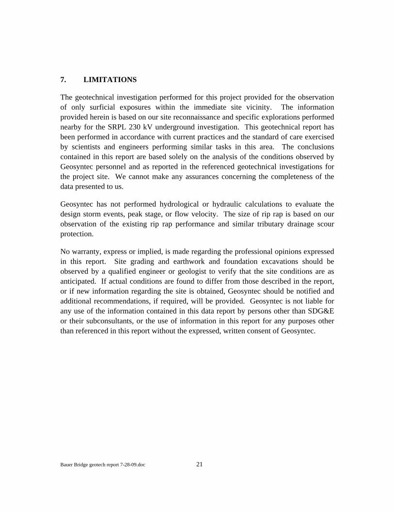
This report presents the results of the geotechnical investigation for the San Diego Gas & Electric Company’s (SDG&E) proposed access bridge associated with the Sunrise Powerlink (SRPL) Project in the Alpine area of San Diego County, California (Figure 1). This report was prepared by Messrs. Alexander Greene, C.E.G., and Steve Fitzwilliam, G.E. and has been reviewed by Mr. Ron Johnson, G.E., of Geosyntec Consultants (Geosyntec), in accordance with the peer review policies of the firm.
1.2 Project Description
We understand that SDG&E is proposing to replace an existing private bridge to provide permanent access to the western end of the underground segment of the Sunrise Powerlink transmission line north of Interstate 8 (I-8). The proposed bridge is located on the Bauer property within Peutz Valley, approximately 450 feet north of the I-8 overpass along the western side of Peutz Valley Road (Figure 1). The proposed bridge, described as a 22 foot wide STEADFAST steel stringer bridge, will replace an existing private bridge that crosses a major tributary drainage to Peutz Valley. At the time of this report the exact length of the bridge had yet to be determined. The location of the proposed bridge is shown on Figure 2.
1.3 Purpose and Scope of Services
The purpose of our geotechnical investigation was to provide geotechnical engineering recommendations for the design and construction of the proposed Bauer property bridge. The scope of the investigation was outlined in our proposal dated 14 July 2009.
This geotechnical engineering report presents our findings, conclusions, and engineering recommendations for excavation and foundation design and includes seismic design parameters in accordance with the 2007 California Building Code [CBC, 2007] for the proposed project. Additionally, the report describes the anticipated subsurface conditions, geology, and a geological engineering evaluation of the potential geologic hazards. This report also provides discussions and recommendations regarding the following:
Bauer Bridge geotech report 7-28-09.doc 5
• Earth pressures and foundation recommendations for permanent structures; • Earth pressures for excavation support; • Soil classification for excavation slopes; • Allowable foundation bearing pressures for bridge foundations; and • Earthwork and on-site grading.

Bauer Bridge geotech report 7-28-09.doc 6
2. FIELD INVESTIGATION
The field investigation consisted of a geologic reconnaissance performed by a Certified Engineering Geologist (C.E.G.) and Geotechnical Engineer (G.E.) on 15 July 2009. Surficial exposures within and adjacent to the active drainage at the proposed crossing were evaluated as part of the geologic reconnaissance. Additionally, details on the existing private bridge were noted and observations regarding stream morphology and localized erosional features were recorded. Results from the geologic reconnaissance were used in combination with data from previous nearby geotechnical explorations and laboratory testing performed for the SRPL 230 kV underground project (Geosyntec, 2009).

Bauer Bridge geotech report 7-28-09.doc 7
3. SITE AND SUBSURFACE CONDITIONS
Our knowledge of the site conditions has been developed from a review of geologic literature, our geologic reconnaissance, professional experience, and field and laboratory investigations performed for the SRPL 230 kV underground project.
3.1 Geologic and Seismic Setting
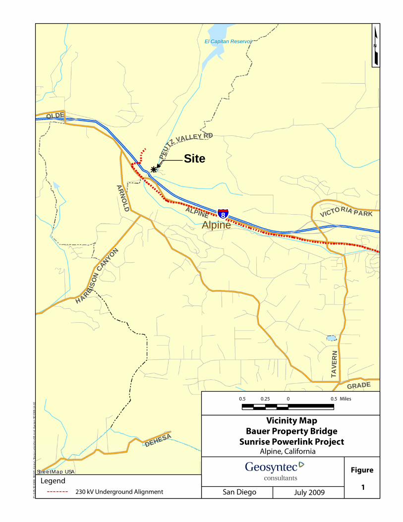
The proposed bridge site is situated within the western Peninsular Ranges physiographic province. Within the general site area the Peninsular Ranges is comprised of igneous rock collectively referred to as the Peninsular Range Batholith (PRB). The PRB is made up of bodies of early Cretaceous-age igneous rocks know as plutons, which formed beneath the surface of the earth from cooled magma. Subsequent uplift and erosion has exposed the crystalline granitic rocks which underlie the site area (Figure 3). Previous regional geologic mapping within the western site area has identified a distinct igneous body identified as the Las Bancas pluton within the immediate site area, classified as a tonalite [Todd, 2004].
Variably weathered tonalitic rock associated with the Las Bancas pluton underlies the entire site area at depth (Figure 3) and is exposed in the steep slopes and road cuts along the eastern side of the drainage extending up above Peutz Valley Road. Within the western PRB the tonalite exhibits a distinctive morphology, typically characterized by relatively low, rolling terrain with scattered dark gray outcrops and grayish soils (Walawender, 2000). The geologic reconnaissance of road cuts along the Bauer driveway and Peutz Valley Road noted the presence of a localized weathering phenomenon known as “core stones” in the exposed crystalline bedrock. The core stones occur as resistant spheroidal boulders in a more weathered matrix and are highly variable in size ranging up to multiple feet in diameter.
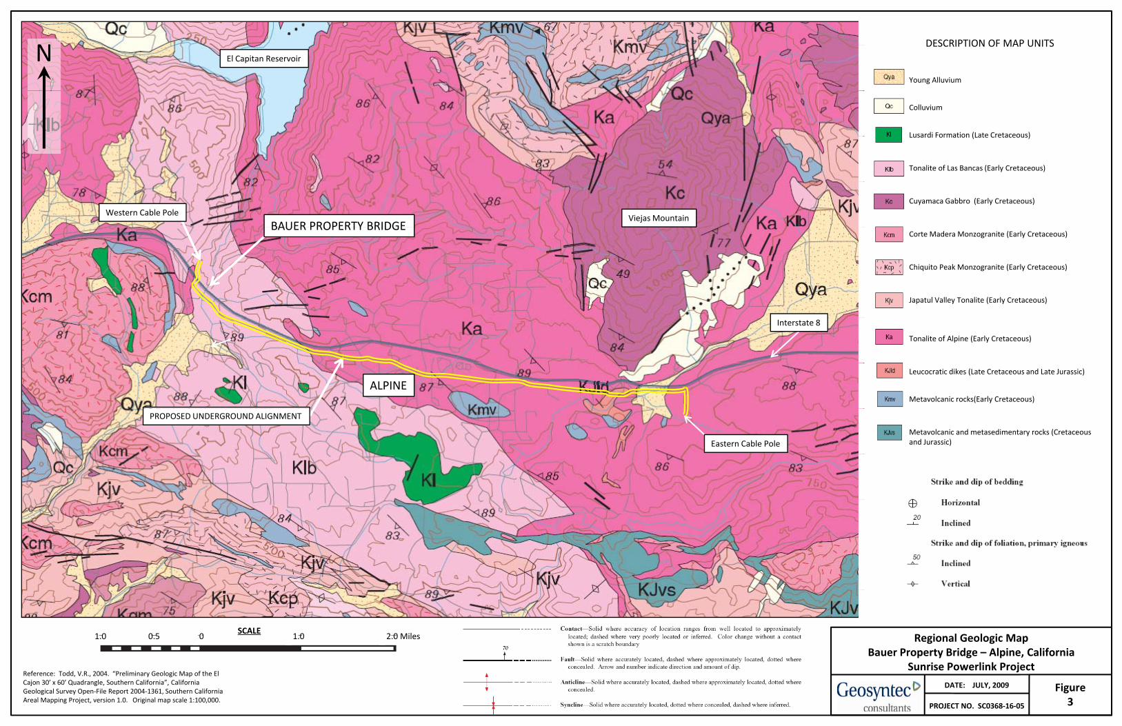
The Peninsular Ranges is known to be seismically active and has experienced historic seismic shaking as a result of activity on both nearby and distant faults. The PRB is dominated by the regional northwest-southeast structure of the San Andreas transform zone which marks the tectonic plate boundary between the North American plate to the east and the Pacific plate to the west. Within the immediate site area, the seismic expression is controlled by the Elsinore and Rose Canyon fault zones situated at respective distances of approximately 21 miles (34 km) east and 22 miles (36 km) west of the project site. A regional fault and epicenter map is presented on Figure 4.
Bauer Bridge geotech report 7-28-09.doc 8
3.2 Surface Conditions
The proposed bridge site is situated within a major tributary drainage to Peutz Valley and contains locally dense vegetation consisting of large oak trees and dense underbrush. The immediate site area is currently occupied by an existing private bridge constructed out of steel I-beams and wooden planks supported by concrete reinforced abutments and two mid-span 24-inch concrete piers with a steel I-beam cross beam. The date of original construction for the existing bridge is uncertain but it appears to have undergone multiple stages of construction and repair.
The drainage is confined within an approximate 20- to 30- foot wide channel and contains a sandy bottom with localized gravels and corestone boulders transported from the surrounding topographic highlands. Upstream of the bridge crossing the eastern channel wall has been eroded exposing a near vertical surface, but placement of concrete and rip-rap scour protection along the southeastern abutment has effectively protected the channel margin in proximity to the bridge. However, scour protection on the southwestern abutment has not worked as effectively and localized erosion along the abutment has occurred.
The existing bridge elevation is approximately +1130 feet, Mean Sea Level (MSL) and the active channel at the crossing is at an approximate elevation of +1120 feet, MSL. The ground surface on the eastern side of the drainage slopes steeply down to the west from Peutz Valley Road into the drainage. To the west, the ground surface climbs more gently up out of the drainage and across several engineered terraces occupied by private residential structures and out-buildings. The active drainage course generally slopes down in a northerly direction, ultimately draining into El Capitan Reservoir.
3.3 Subsurface Conditions
The bridge site is underlain by surficial alluvial and fill deposits and variably weathered tonalitic bedrock. Surficial fill associated with the construction of the existing bridge abutments and driveway is composed of silty fine sands and gravels likely derived from the adjacent eastern slope face. Alluvial deposits are encountered within the active drainage and are comprised of dark grayish brown, poorly graded fine sand with localized coarse sand and gravels. Based on the geometry of the adjacent slopes, it is anticipated that the alluvial deposits may extend to a depth of 10 feet or more within the narrow drainage bottom.
Bauer Bridge geotech report 7-28-09.doc 9
The crystalline rock exposed in the active channel and along the steep eastern slopes is highly to moderately weathered and weak with the exception of localized resistant core stones. These similar conditions were encountered within the limits of the previous explorations performed nearby, in which the weathering profile of the crystalline rock extended relatively deep with generally low strengths (Geosyntec, 2009). Just west of the site, at the western cable pole location for the SRPL 230 kV underground, resistant granitic rock that was difficult to excavate with an auger was encountered at a depth of 14.75 feet into the rock.
3.4 Groundwater
Surface flow, and therefore groundwater was observed in the drainage at an approximate elevation of +1120 feet, MSL at the time of our geologic reconnaissance. Based on visual observations of channel margin scour and personal communication with the property owner, the peak flow depth during storm events can exceed several feet.
Bauer Bridge geotech report 7-28-09.doc 10
4. SEISMIC AND GEOLOGIC HAZARDS
4.1 Seismic Hazards
4.1.1 Fault Ground Rupture
Fault rupture is not considered to be a constraint to the proposed construction of the bridge studied within this investigation. The potential for fault surface rupture is generally considered to be significant along “active” faults (defined as exhibiting surface rupture within the past 11,000 years) and to a lesser degree along “potentially active” faults (surface rupture within the past 1.6 million years). A review of published geologic maps did not identify the presence of any active or potentially active faults crossing on or projecting near the project site. The nearest mapped active fault traces are approximately 21 miles (34 km) to the northeast of the project area within the Elsinore fault zone, and 22 miles (36 km) to the west-southwest within the Rose Canyon fault zone [Jennings, 1994]. Therefore it is our opinion that the potential for fault related surface rupture along the proposed project alignment is low.
4.1.2 Strong Ground Shaking
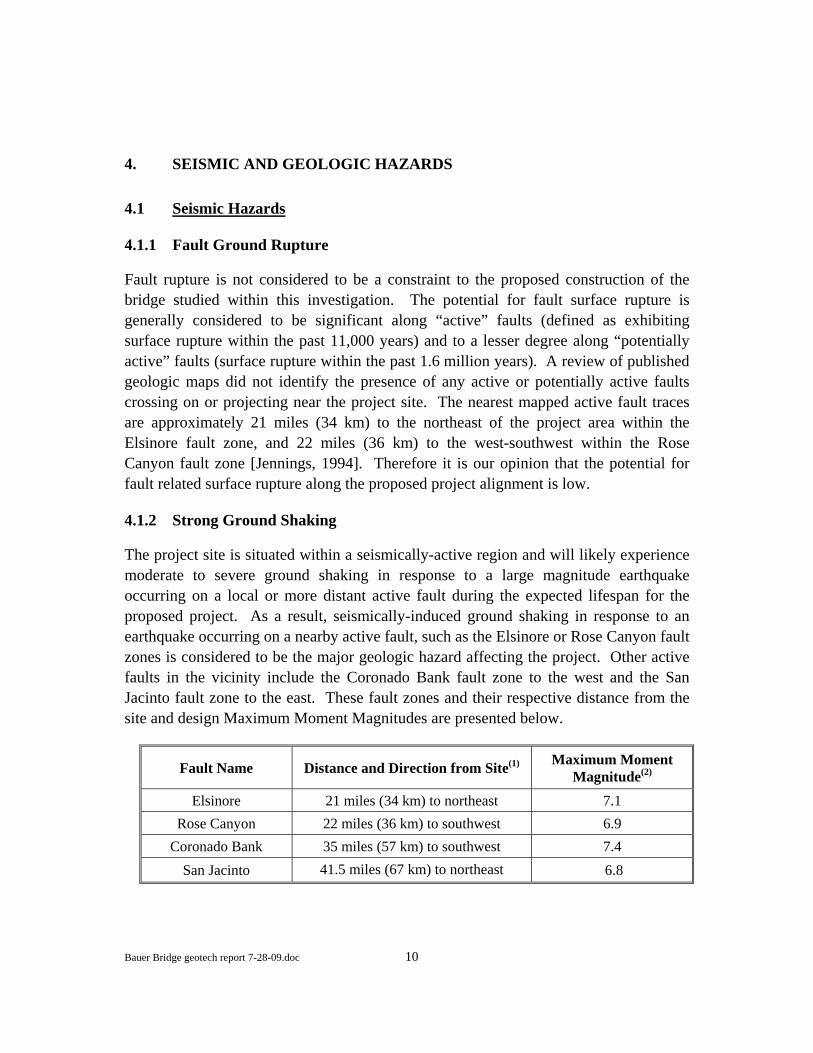
The project site is situated within a seismically-active region and will likely experience moderate to severe ground shaking in response to a large magnitude earthquake occurring on a local or more distant active fault during the expected lifespan for the proposed project. As a result, seismically-induced ground shaking in response to an earthquake occurring on a nearby active fault, such as the Elsinore or Rose Canyon fault zones is considered to be the major geologic hazard affecting the project. Other active faults in the vicinity include the Coronado Bank fault zone to the west and the San Jacinto fault zone to the east. These fault zones and their respective distance from the site and design Maximum Moment Magnitudes are presented below.
Fault Name Distance and Direction from Site(1) Maximum Moment Magnitude(2)
Elsinore 21 miles (34 km) to northeast 7.1 Rose Canyon 22 miles (36 km) to southwest 6.9
Coronado Bank 35 miles (57 km) to southwest 7.4 San Jacinto 41.5 miles (67 km) to northeast 6.8
Bauer Bridge geotech report 7-28-09.doc 11
(1) Distances from site noted are the closest distance to the surface trace or inferred projection of the fault as measured from the California Division of Mines and Geology (1998).
(2) Maximum moment magnitude values reported by California Division of Mines and Geology [CDMG, 1998].
Specific seismic design recommendations are presented in the Design Recommendations section of this report. The location of regional faults and historic earthquake epicenters are shown on Figure 4.
USGS’s National Seismic Hazards Mapping Program (USGS, 1996) performed a probabilistic seismic hazard assessment (PSHA) which included the continental United States. The USGS PSHA established ground motion parameters for soft rock/stiff soil conditions (NEHRP Site Class B-C; an average shear wave velocity in the top 100 feet of 2,500 feet per second) which are subject to modification (based on amplification effects) for hard rock and soft soil sites. Based on this mapping, the equivalent soft rock/stiff soil PGA at the site corresponding to a probability of exceedence of 10-percent in 50-years (a recurrence interval of 475-years) is about 0.19g. The equivalent soft rock/stiff soil PGA corresponding to a probability of exceedence of 2-percent in 50 years (a recurrence interval of 2,475 years) is about 0.35g.
4.1.3 Soil Liquefaction
Seismically-induced soil liquefaction can be described as a significant loss of strength and stiffness due to cyclic pore water pressure generation from seismic shaking or other large cyclic loading. The material types considered most susceptible to liquefaction are granular soils and low-plasticity fine grained soils which are saturated and loose to medium dense. Manifestations of soil liquefaction can include the loss of bearing capacity below foundations, surface settlements and tilting in level ground, and instabilities in areas of sloping ground. Soil liquefaction can also result in increased lateral and uplift pressures on buried structures. Lightweight or unrestrained buried structures may float upward to the ground surface during a liquefaction event.
Within the active drainage channel the probability of soil liquefaction is considered to be moderate to high given the presence of the saturated unconsolidated granular alluvium. However, the alluvium is anticipated to be relatively thin, if present at all at the proposed foundations locations. Given the dense nature of the crystalline bedrock underlying the surficial alluvium, the probability of soil liquefaction is considered very low if the proposed foundations penetrate the surficial deposits and are founded on weathered bedrock.
Bauer Bridge geotech report 7-28-09.doc 12
4.1.4 Secondary Effects of Seismic Activity
The secondary effects of seismic activity resulting from ground shaking include liquefaction-induced settlement, lateral spreading, tsunamis and seiches. The probability of occurrence of each depends on the severity of earthquake, distance from the epicenter, faulting mechanism, topography, soil and groundwater conditions, and other factors.
Due to the very low potential for soil liquefaction if foundations are founded on weathered bedrock, the potential for damage due to seismic settlement and lateral spreading is also considered very low.
Tsunamis are seismically-induced waves generated by sudden movements of the ocean bottom during submarine earthquakes, landslides, or volcanic activity. Seiches are similarly generated, but are waves in lakes or reservoirs. Based on the inland location, site elevation, and the location and lower elevation of the nearest large body of water (El Capitan Reservoir), the potential for damage due to a tsunami or seiche is considered very low and does not constitute a significant developmental hazard for the project.
4.2 Geologic Hazards
4.2.1 Landslides and Slope Stability
In general, the crystalline bedrock that outcrops at the site is not considered landslide prone and previous and current mapping efforts have not identified landslides within the vicinity. As a result landslides are not considered to constitute a significant developmental hazard for the proposed construction of the project.
4.2.2 Expansive Soil
Based on visual observations from our site reconnaissance, the near-surface soil is not considered to be expansive. Furthermore, laboratory testing performed on similar material as part of the SRPL 230 kV underground investigation collaborate our observations in accordance with California Building Code Section 1802A.3.2 [CBC, 2007].
Bauer Bridge geotech report 7-28-09.doc 13
4.2.3 Collapsible Soil
Collapsible soils are not present in significant quantities within the site area and do not constitute a significant hazard during project construction.
4.2.4 Other Geologic Hazards
Other geologic hazards, including volcanic activity, are not considered to be a significant hazard given the geologic setting of the site. However creek bank scour may occur during high water storm events. Creek bank erosion and scour may undermine the proposed bridge foundations if erosion-control protection measures are not included in the project design.

Bauer Bridge geotech report 7-28-09.doc 14
5. DESIGN RECOMMENDATIONS
The recommendations presented in this report are intended for the proposed construction of the Bauer property access bridge in the Alpine area of San Diego County, California. Further, the recommendations presented are based on our understanding of the proposed project, our site reconnaissance, and field explorations and laboratory testing performed for the SRPL 230 kV underground project (Geosyntec, 2009). In our opinion, the site is suitable for the construction of the proposed project.
5.1 Soil Characteristics and Anticipated Ground Conditions
Results of our geologic reconnaissance indicate that the near-surface fill and alluvial deposits consist primarily of silty fine sand, poorly graded sand, and sandy gravel. The soils exposed within the immediate site area and encountered in the previous subsurface explorations performed nearby may be classified as having a low expansion potential (Geosyntec, 2009).
Ground conditions at the site are anticipated to consist of surficial fills, alluvium, and weathered granitic rock. Subsurface obstructions from buried debris in the fill materials associated with the existing bridge abutments may be encountered and difficult to penetrate. Additionally, core stones within the weathered granitic rock or in the alluvial deposits may be encountered.
5.2 Site Preparation, Grading, and Compaction
The site approaches are currently underlain by thin fills, alluvial soils, and weathered granitic rock. We anticipate that the final elevation of the bridge approaches may be raised to accommodate the new bridge. Loose or soft soil within the proposed area to receive new fill, as identified by the geotechnical consultant in the field at the time of grading and foundation excavation should be excavated or scarified as required, brought to the proper moisture content, and then recompacted before placing additional fill or preparing subgrade. Soil containing organic or other deleterious matter, if encountered, should be removed from the site and properly disposed.
Areas to receive new fill on the site should be prepared prior to compacting new fill. The top 6 inches of the area to receive new fill should be scarified, moisture conditioned, and recompacted to a minimum of 90 percent relative compaction. Relative compaction is defined as the ratio (in percent) of the in-place measured dry
Bauer Bridge geotech report 7-28-09.doc 15
density of the compacted fill (as determined in accordance with ASTM D-6938) divided by the maximum laboratory dry density (as determined in accordance with ASTM D-1557). Fill should be compacted between 0 and 3 percent above the optimum moisture contents in layers that do not exceed 8-inch loose lifts for heavy equipment compaction and 4-inch loose lifts for hand held equipment compaction. Materials used for fill should be mineral soils and should not contain rocks, clods, or hard lumps over 6 inches in maximum dimension. Fill material used as backfill behind walls and for utility trenches should consist of sandy, cohesionless material and contain at least 40 percent of material, by dry weight, less than ¼ inch in size. Biodegradable, organic, or compressible material should not be used as fill. Most of the on-site soil will be suitable for use as fill and backfill material. Fill and backfill material should have an Expansion Index of less than 50.
As the ground surface at the site currently slopes into the creek, natural drainage for the site is provided. The cut and fill and general minor site grading will be consistent with current drainage conditions. Due to the relatively thin fill thickness at the site and shallowness of the formational material, new subsurface subdrains are not necessary.
5.3 Foundations
The proposed bridge may be founded on drilled pier foundations. We recommend that the drilled pier foundation be located behind the existing abutments, such that the proposed bridge will span beyond the length of the existing bridge at the site. By installing the drilled pier foundations behind the existing abutments, obstructions such as the concrete abutments of the existing bridge and the rip rap slope protection may be avoided during foundation excavation. These obstructions may make the foundation excavation difficult, if not avoided. Midspan foundations are not anticipated. If midspan foundations are required, additional geotechnical foundation recommendations will be needed.
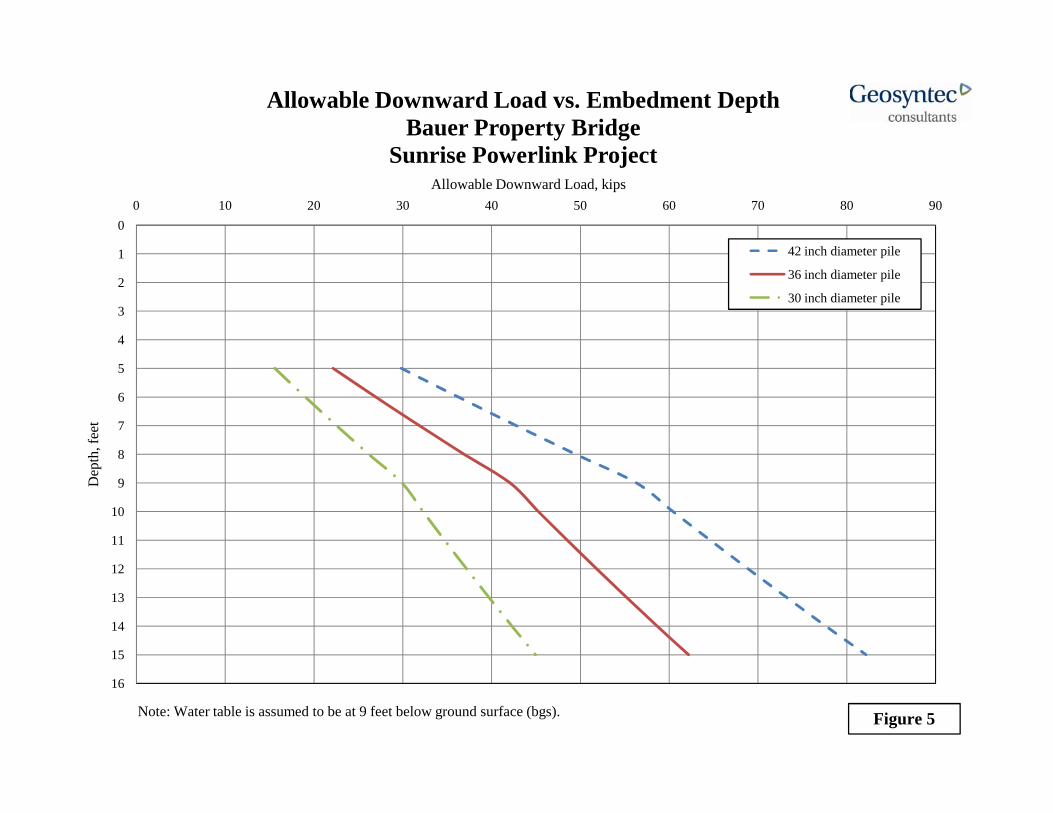
Drilled pier foundations should extend a minimum of 5 feet below the existing ground surface, bear in weathered granitic rock, and should have a minimum diameter of 30 inches. Drilled pier foundations may be designed for an allowable downward load as presented in Figure 5 for 30, 36, or 42 inch diameter piers. This value may be increased by one-third for wind and seismic loading. The bearing strata for the foundations should be verified in the field by the geotechnical engineer. Lateral loading on the drilled piers may be resisted by a uniform pressure of 250 pounds per square foot on an area that is twice the diameter of the pier. For instance, a two foot diameter pier that is five foot deep will be resisted by a uniform pressure over an area of 20 square feet. To

Bauer Bridge geotech report 7-28-09.doc 16
achieve full lateral resistance, the drilled piers should be spaced at minimum of three diameters on center. If closer spacing is required, additional engineering recommendations will be required for a reduced lateral resistance.
The allowable design loads presented herein are based on the assumption that groundwater may be seasonally present at a depth of approximately 9 feet (elevation +1121 feet, MSL) below the top of the abutment level. The drilled piers foundation excavation should be performed during the dry season, so that standing water is not present at the base of the excavation.
Total and differential settlements of foundations are expected to be within tolerable ranges. Total settlement is not expected to exceed 1 inch, while differential settlement between drilled piers is not expected to exceed about ½ inch.
5.4 Scour and Erosion Control
As the bridge crosses and active creek, scour and erosion of the creek banks is expected. The existing concrete bridge abutments and rip rap along the creek banks will help to control the scour within the creek channel. We recommend that these features be left in place. However, the western abutment shows signs of erosion. We recommend that scour and erosion protection be added to the western embankment to protect the western bridge abutment. In particular, erosion protection should be placed near the drainage channel from the western driveway into the creek channel. We recommend that 3- to 5-foot diameter rip rap be placed along western abutment to protect the abutment from scour. We understand that hydrologic and hydraulic analyses have not been performed for the creek for this project. The recommendations for scour and erosion protection are based on experience with similar projects and on-site observations of the existing conditions.
5.5 2007 CBC Seismic Design Considerations
Seismic design parameters were developed in accordance with Chapter 16 of the 2007 CBC. We recommend that the values listed below be used for design:

Bauer Bridge geotech report 7-28-09.doc 17
2007 CBC1 Seismic Design Parameters (2% Probability of Exceedence in 50 years)
Soil Class D Mapped Spectral Response Acceleration at 0.2s Period, SS 1.07g Mapped Spectral Response Acceleration at 1.0s Period, S1 0.36g Short Period Site Coefficient at 0.2s Period, Fa 1.07 Long Period Site Coefficient at 1.0s Period, Fv 1.682 Adjusted Spectral Response Acceleration at 0.2s Period, SMS 1.15g Adjusted Spectral Response Acceleration at 1.0s Period, SM1 0.60g Design Spectral Response Acceleration at 0.2s Period, SDS 0.76g Design Spectral Response Acceleration at 1.0s Period, SD1 0.40g 1 CBC, 2007, “California Code of Regulations, Title 24, Part 2, Vol. 2 of 2,” Building Code (Based on 2006 International Building Code), California Building Standard Commission, Sacramento, California.
These are minimum values. The structural designer may utilize more conservative values at their discretion.
5.6 Corrosion Potential
Corrosion testing was performed on samples of the near-surface soils from nearby explorations for the SRPL 230 kV underground investigation (Geosyntec, 2009). The results of these tests indicate the water soluble sulfate content of the soil were in the range of 0 to 100 parts per million (ppm). Sulfate contents in this range are generally considered to be negligible with respect to potential for sulfate attack of concrete in accordance with Table 4.3.1 of the 2005 American Concrete Institute (ACI) Manual. Based on soil resistivity tests (between approximately 1,800 and 53,000 ohm-cm), metallic utility piping and conduits should be designed for a moderately corrosive to corrosive environment. A corrosion engineer should be consulted if additional corrosion information is needed.
5.7 Pavements
Based on our experience and observations of the existing paved driveway, we recommend that the pavement sections at the project site such as the bridge approach be designed for a Traffic Index (T.I.) of 6. The pavement section should consist of asphalt concrete (AC) over Class 2 aggregate base (as defined in Section 26 of the Caltrans

Bauer Bridge geotech report 7-28-09.doc 18
Standard Specifications) over properly prepared subgrade. The subgrade soils should be proof-rolled prior to placing the pavement section. AC and aggregate base should be compacted to a minimum relative compaction of 95 percent. Based on laboratory testing performed for the SRPL project, we recommend the use of an R-value of 50 in design. We recommend that a minimum pavement section of 4 inches of AC over 4 inches of Class 2 aggregate based be used for the bridge approaches.

Bauer Bridge geotech report 7-28-09.doc 19
6. CONSTRUCTION CONSIDERATIONS
6.1 Shoring
Bracing of the foundation excavations may be required as loose, cohesionless soils are anticipated. Drilled pier foundation excavations should be cased during excavation using steel casing. The casing may be removed during concrete placement. Difficult drilling should be anticipated in less weathered crystalline rock or where core stones are present.
Casing for the foundation excavations should be designed and constructed in accordance with current OSHA regulations. An OSHA soil classification of C should be used for construction planning. The contractor’s “Competent Person”, in accordance with OSHA regulations, should confirm these soil classifications. Design of the shoring and bracing system (casing) is the responsibility of the contractor. The contractor should retain an engineer experienced in designing shoring systems. The shoring parameters presented in this report are for reference and preliminary design only; the contractor should develop his own parameters for final shoring design.
The shoring system should be designed to resist lateral earth pressures plus additional horizontal pressures imposed by adjacent surcharge loads. We recommend the shoring be preliminarily designed for a lateral soil pressure of 22H pounds per square foot, where H represents the height of retained soil.
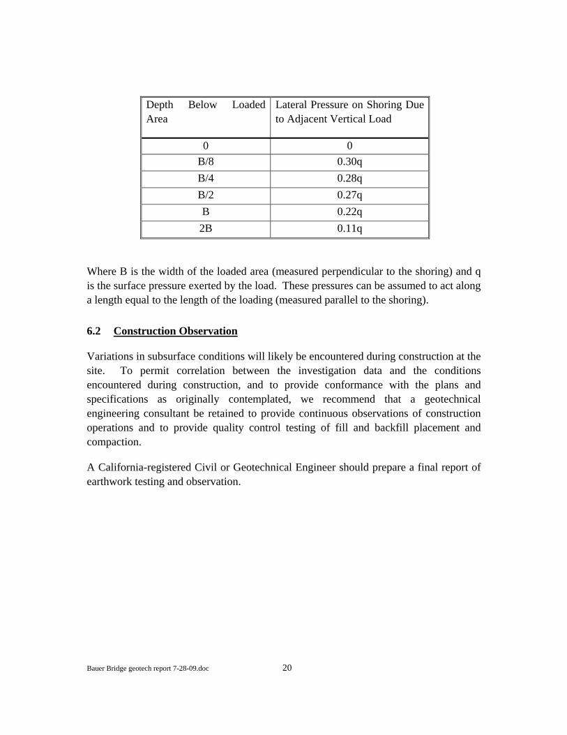
Lateral loads will also be imposed on the shoring due to loads placed adjacent to the shoring (i.e., crane tracks or stockpiled materials). The lateral stress imposed on shoring with loads immediately adjacent can be estimated as follows:
Bauer Bridge geotech report 7-28-09.doc 20
Depth Below Loaded Area
Lateral Pressure on Shoring Due to Adjacent Vertical Load
0 0 B/8 0.30q B/4 0.28q B/2 0.27q B 0.22q 2B 0.11q
Where B is the width of the loaded area (measured perpendicular to the shoring) and q is the surface pressure exerted by the load. These pressures can be assumed to act along a length equal to the length of the loading (measured parallel to the shoring).
6.2 Construction Observation
Variations in subsurface conditions will likely be encountered during construction at the site. To permit correlation between the investigation data and the conditions encountered during construction, and to provide conformance with the plans and specifications as originally contemplated, we recommend that a geotechnical engineering consultant be retained to provide continuous observations of construction operations and to provide quality control testing of fill and backfill placement and compaction.
A California-registered Civil or Geotechnical Engineer should prepare a final report of earthwork testing and observation.
Bauer Bridge geotech report 7-28-09.doc 21
7. LIMITATIONS
The geotechnical investigation performed for this project provided for the observation of only surficial exposures within the immediate site vicinity. The information provided herein is based on our site reconnaissance and specific explorations performed nearby for the SRPL 230 kV underground investigation. This geotechnical report has been performed in accordance with current practices and the standard of care exercised by scientists and engineers performing similar tasks in this area. The conclusions contained in this report are based solely on the analysis of the conditions observed by Geosyntec personnel and as reported in the referenced geotechnical investigations for the project site. We cannot make any assurances concerning the completeness of the data presented to us.
Geosyntec has not performed hydrological or hydraulic calculations to evaluate the design storm events, peak stage, or flow velocity. The size of rip rap is based on our observation of the existing rip rap performance and similar tributary drainage scour protection.
No warranty, express or implied, is made regarding the professional opinions expressed in this report. Site grading and earthwork and foundation excavations should be observed by a qualified engineer or geologist to verify that the site conditions are as anticipated. If actual conditions are found to differ from those described in the report, or if new information regarding the site is obtained, Geosyntec should be notified and additional recommendations, if required, will be provided. Geosyntec is not liable for any use of the information contained in this data report by persons other than SDG&E or their subconsultants, or the use of information in this report for any purposes other than referenced in this report without the expressed, written consent of Geosyntec.

8. REFERENCES
American Society for Testing and Materials (ASTM), 2005. “Annual Book of ASTM Standards”, Section 4 Construction. Volume 04.08 Soil and Rock.
California Building Code (CBC), 2007. Title 24, Part 2. Volume 2. 2007 edition.
California Divisions of Mines and Geology, 1998. “Maps of Known Active Fault Near-Source Zones in California and Adjacent Portions of Nevada”, prepared for International Conference of Building Officials to be used with 1997 UBC, dated February, 1998.
Geosyntec Consultants, 2009. “ Geotechnical Investigation - Sunrise Powerlink Project 230 kV Underground, Alpine, California”, report prepared for San Diego Gas & Electric dated June 18, 2009.
Jennings, C.W., 1994. “Fault Activity Map of California and Adjacent Areas, with Locations and Ages of Recent Volcanic Eruptions”, California Department of Conservation, Division of Mines and Geology, Geologic Data Map Series, Map No. 6- Faults, Locations of recent Volcanic Eruptions, map scale 1:750,000
Todd, V.R., 2004. “Preliminary Geologic Map of the El Cajon 30’x 60’ Quadrangle, Southern California”, California Geological Survey Open-File Report 2004-1361, Southern California Areal Mapping Project (SCAMP), version 1.0, map scale 1:100,000.
United States Geological Survey, 2008. “National Seismic Hazards Mapping Program” (USGS, 1996), http://earthquake.usgs.gov/research/hazmaps/design.
Walawender, M.J., 2000. “The Peninsular Ranges – A Geological Guide to San Diego’s Back Country”, Chapter 4 – The Peninsular Ranges Batholith, pp 33-47.

FIGURES
ALPINE
PEUT
Z VALLEY RD
§̈¦8
TAVE
RN
DEHESA
ARNO
LD
HARBIS
ON
CANYONOLDE
VICTORIA PARK
JAPATUL
GRADE
DE HESA
El Capitan ReservoirEl Capitan Reservoir £
Vicinity MapBauer Property Bridge
Sunrise Powerlink ProjectAlpine, California
Figure
1
P:\G
IS\S
C03
68_S
DG
E\A
lpin
e\Si
teLo
ca
tionN
ov0
8.m
xd;J
Lars
on;
SC03
68-1
4-02
San Diego July 2009
0.5 0 0.50.25 Miles
Alpine
230 kV Underground Alignment
LegendStreetMap USA
-------
Sitek

<< <<
<
<
<
<
Proposed BridgeLocation
B-1
CP-1
I8-3I8-2
I8-1
I8-2A
B-3
B-2
£
Site PlanBauer Property Bridge
Sunrise Powerlink ProjectAlpine, California
Figure
2
P:\G
IS\S
C03
68_S
DG
E\A
lpin
e\Ba
uer
\Ba
uer
Site
Pla
n.m
xd
San Diego July 2009
500 0 500250 Feet
Previous Boring Performed on Sunrsie Powerlink
230 kV Underground Alignment
Legend
-------
<
DESCRIPTION OF MAP UNITSN El Capitan Reservoir
Young Alluvium
DESCRIPTION OF MAP UNITSN
Colluvium
Lusardi Formation (Late Cretaceous)Lusardi Formation (Late Cretaceous)
Tonalite of Las Bancas (Early Cretaceous)
Cuyamaca Gabbro (Early Cretaceous)
Viejas MountainWestern Cable Pole
BAUER PROPERTY BRIDGECorte Madera Monzogranite (Early Cretaceous)
Chiquito Peak Monzogranite (Early Cretaceous)
BAUER PROPERTY BRIDGE
Japatul Valley Tonalite (Early Cretaceous)
Interstate 8
Tonalite of Alpine (Early Cretaceous)
Leucocratic dikes (Late Cretaceous and Late Jurassic)
Metavolcanic rocks(Early Cretaceous)
ALPINE
PROPOSED UNDERGROUND ALIGNMENT
Eastern Cable PoleMetavolcanic and metasedimentary rocks (Cretaceous and Jurassic)
R i l G l i M2 0 Miles0 5 1 01 0 0SCALE
Regional Geologic MapBauer Property Bridge – Alpine, California
Sunrise Powerlink Project
2.0 Miles0.5 1.01.0 0
Reference: Todd, V.R., 2004. “Preliminary Geologic Map of the El C j 30’ 60’ Q d l S th C lif i ” C lif i Figure
3
DATE: JULY, 2009
PROJECT NO. SC0368‐16‐05
Cajon 30’ x 60’ Quadrangle, Southern California”, California Geological Survey Open‐File Report 2004‐1361, Southern California Areal Mapping Project, version 1.0. Original map scale 1:100,000.
k
!?!?
!?
!?
!?
!?!?
!?!?
!?
!?
!?
!?!?
!?
!?
!?
!?
!?
!?
!?!?
!?
!?
!?
!?
!?!? !?
!?
!?!?
!?
!?
!?!?
!?!?
!? !?
!?
!?
!?
!?!?
!?!?
!?
!?
!?
!?
!?
!?
!?
!?
!?
!?
!?
!?!?
!?
!?
!?
!?
!?
!?
!?!?!?!?
!?!? !?
!?!? !?
!? !?
!?
!?
!?
!?
!?
!?
!? !?
!?
!?
!?
!?
!?
!?
!?
!?
!?
!?
!?
!?
!?!? !?
!?
!?
!?
!?
!?
!?
!?
!?!?
!?
!?!?!?!?
!?
!?!?
!?!?
!?!?!?
!?
!?
!?
!?
!?
!?
!?
!?
!?
!?
!?
!?
!?
!?
!?
!?
!?
!?
!?
!?
!?
!?
!?
!?
!?
!?!?
!?
!?
!?
!?
!?
!?
!?!?!?!?
!?
!?!?!?!?!?!?!?!?
!?
!?!?!?
!?!?
!?!?!?!?
!?
!?
!?
!?
!?
!?
!?
!?
!?!?!?
!?
!?
!?
!?
!?
!?
!?!?!?!?
!?
!?
!?!? !?
!?
!?
!?
!?
!?!?
!?
!?
!?
!?
!?
!? !?
!?
!?
!?
!?
!?!?
!?
!?
!?
!?
!?
!?
!?
Cleveland NF
Anza-Borrego Desert State Park
Cleveland NFSan Bernardino NF
Cleveland NF
Joshua Tree NP
Potrero County Park
Anza-Borrego Desert State Park
Regional Fault and Epicenter MapBauer Property Bridge
Sunrise Powerlink ProjectAlpine, California
Figure
4San Diego July 2009
10 0 10 20 305 Kilometers
£
P:\G
IS\S
C03
68_S
DG
EAlp
ine_
Seism
ic.m
xd;J
lars
o;M
ay2
009
ESRI_StreetMap_World_2D
Site Location
100 Kilometer Radius
Elsinore Fault Zone
San Andreas Fault Zone
Rose Canyon
San Jacinto Fault Zone
Newport - Inglewood
Fault Zone
Coronado Bank Fault Zone
San Diego Trough Fault Zone
San Clemente Fault Zone
Legend
Fault
!?!?
4.0 - 4.99
5.0 - 5.99
6.0 - 6.6
Data Source: Southern California Earthquake Data CenterImage Source: ArcOnline NGS_Topo_US_2D
Reported Earthquake Magnitudes 1932 - 2008
!?
0
1
2
3
4
5
0 10 20 30 40 50 60 70 80 90Allowable Downward Load, kips
Allowable Downward Load vs. Embedment DepthBauer Property Bridge
Sunrise Powerlink Project
42 inch diameter pile
36 inch diameter pile
30 inch diameter pile
6
7
8
9
10
11
12
13
14
15
16
Dep
th, f
eet
Figure 5Note: Water table is assumed to be at 9 feet below ground surface (bgs).