Embed Size (px)
Citation preview

14/1 Cowpasture Place, Wetherill Park, NSW 2164, Australia
(PO Box 6989, Wetherill Park, NSW 2164, Australia) T +61 2 9756 2166 | F +61 2 9756 1137
www.stsgeo.com.au | [email protected] ABN 61 162 976 543 | ACN 162 976 543
GEOTECHNICAL INVESTIGATION AND
ACID SULFATE SOIL ASSESSMENT
FOR
NSW LAND & HOUSING CORPORATION
15 – 19 Fieldsend Street, East Maitland, New South Wales
Report No: 19/0719
Project No: 10530/3045
March 2019

Page 1 Project No: 10530/3045 March 2019 Report No: 19/0719
Table of Contents
1. INTRODUCTION ....................................................................................................................... 2
2. NATURE OF THE INVESTIGATION ........................................................................................... 2
2.1. Fieldwork ........................................................................................................................ 2
2.2. Laboratory Testing .......................................................................................................... 3
3. GEOLOGY AND SITE CONDITIONS ........................................................................................... 3
4. SUBSURFACE CONDITIONS ..................................................................................................... 4
5. GEOTECHNICAL DISCUSSION .................................................................................................. 4
5.1. Site Classification to AS2870 ........................................................................................... 4
5.2. Foundation Design .......................................................................................................... 5
5.3. Soil Aggressiveness ......................................................................................................... 5
6. ACID SULFATE SOIL ASSESSMENT ........................................................................................... 6
6.1. Introduction .................................................................................................................... 6
6.2. Presence of ASS .............................................................................................................. 7
6.3. Assessment ..................................................................................................................... 7
7. FINAL COMMENTS .................................................................................................................. 9
DRAWING NO. 19/0719 – BOREHOLE AND PENETROMETER LOCATIONS
NOTES RELATING TO GEOTECHNICAL REPORTS
APPENDIX A – BOREHOLE LOGS AND EXPLANATION SHEETS
APPENDIX B – LABORATORY TEST RESULTS

Page 2 Project No: 10530/3045 March 2019 Report No: 19/0719
1. INTRODUCTION
This report presents the results of a combined Geotechnical Investigation and Acid Sulfate Soil
(ASS) assessment carried out by STS GeoEnvironmental Pty Limited (STS) for a proposed new
residential development to be constructed at 15 – 19 Fieldsend Street, East Maitland. At the
time of writing this report STS were not provided with architectural drawings for the project,
however we understand the development will typically comprise construction of one to two
level residential unit type buildings. The development will not include a basement. We
understand that the site is located within a Class 5 Acid Sulfate Soils area, and therefore the
client requires an assessment to be undertaken.
The purpose of the investigation was to:
• assess the subsurface conditions over the site,
• provide a Site Classification to AS2870,
• provide recommendations regarding the appropriate foundation system for the site
including design parameters,
• comment on soil aggressiveness to buried steel and concrete,
• undertake an ASS assessment, and
• determine if an ASS Management Plan is required.
The investigation was undertaken at the request of Land and Housing Corporation NSW.
Our scope of work did not include a contamination assessment.
2. NATURE OF THE INVESTIGATION
2.1. Fieldwork
The fieldwork consisted of drilling five (5) boreholes numbered BH1 to BH5, at the locations
shown on Drawing No. 19/0719. BH1 to BH4, inclusive, were drilled using a utility mounted
Edson RP70 drilling rig owned and operated by STS. Soils and weathered bedrock in these
boreholes were drilled using rotary solid flight augers. Due to restricted site access, BH5 was
drilled using a hand auger. Soil strengths were determined by undertaking Dynamic Cone
Penetrometer (DCP) tests at each borehole location.
Drilling operations were undertaken by one of STS’s senior geologists who also logged the
subsurface conditions encountered.

Page 3 Project No: 10530/3045 March 2019 Report No: 19/0719
The subsurface conditions observed are recorded on the borehole logs given in Appendix A. An
explanation of the terms used on the logs is also given in Appendix A. Notes relating to
geotechnical reports are also attached.
2.2. Laboratory Testing
In order to assess the soils for their aggressiveness selected representative soil samples were
tested to determine the following:
• pH,
• Sulphate content (SO4),
• Chloride content (CL), and
• Electrical Conductivity (EC)
Based on field observations, three soil samples were also selected for laboratory analysis for the
Acid Sulfate Soils assessment. The samples were dispatched to Australian Laboratory Services
(ALS) for analysis using the Suspension Peroxide Oxidation Combined Acidity and Sulphate
(SPOCAS) method. The method allows both a measure of the existing and potential acidity.
Detailed test reports are given in Appendix B.
3. GEOLOGY AND SITE CONDITIONS
The Newcastle Coalfield Series geological sheet at a scale of 1:100,000 indicates that the site is
underlain by Permian Age bedrock belonging to the Tomago Coal Measures. Bedrock within this
group comprises interbedded lithic sandstone, coal, carbonaceous claystone, siltstone and
claystone.
The site is rectangular in shape with a combined area of approximately 2,021m2. At the time of
the fieldwork, the site was occupied by a series of single level weatherboard clad residential
dwellings with tile roofs, concrete driveways, separate sheds, outbuildings and awnings. Site
vegetation comprised grass, trees and shrubs.
The ground surface falls approximately 1.8 metres to the north – north west.
To the north east of the site is Fieldsend Street and to the south east is Alliance Street. To the
north west and south west of the site are single level residential dwellings.

Page 4 Project No: 10530/3045 March 2019 Report No: 19/0719
4. SUBSURFACE CONDITIONS
When assessing the subsurface conditions across a site from a limited number of boreholes,
there is the possibility that variations may occur between test locations. The data derived from
the site investigation programme are extrapolated across the site to form a geological model
and an engineering opinion is rendered about overall subsurface conditions and their likely
behaviour regarding the proposed development. The actual condition at the site may differ
from those inferred, since no subsurface exploration programme, no matter how
comprehensive, can reveal all subsurface details and anomalies.
The subsurface conditions generally consist of topsoil and fill overlying silty clays and silty sandy
clays, overlying sandstone and shale bedrock. Topsoil and fill materials were encountered in all
boreholes to depths of 0.2 to 0.5 metres. Natural silty clays and silty sandy clays were
encountered below the topsoil and fill to depths of 0.9 to 1.7 metres. The consistency of the
clays varies from firm to very stiff. The clayey soils could not be penetrated with a hand auger
in BH5. Weathered shale and sandstone bedrock underlie the site to the depth of auger refusal,
1.3 to greater than 3.0 metres.
Groundwater was not observed during drilling of the boreholes.
5. GEOTECHNICAL DISCUSSION
5.1. Site Classification to AS2870
The results of the shrink swell test are summarised in Table 5.1 below:
Table 5.1 – Shrink Swell Summary Table
Location Depth (m)
Material Description Shrink/Swell Index
(% per pF)
BH1 0.60 – 0.80 Light grey with orange brown silty clay
3.6
BH2 0.60 – 0.78 Orange brown with light grey silty clay
0.6
BH4 0.40 – 0.60 Orange brown with light grey silty clay 0.6
The classification has been prepared in accordance with the guidelines set out in the
“Residential Slabs and Footings” Code, AS2870 – 2011.
Because there are buildings and trees present, abnormal moisture conditions (AMC) prevail at
the site (Refer to Section 1.3.3 of AS2870).
Because of the AMC and fill present, the site is classified a problem site (P). Provided the
recommendations given below are adopted and the footings bear in the underlying natural soils,
the site may be reclassified highly reactive (H1).

Page 5 Project No: 10530/3045 March 2019 Report No: 19/0719
5.2. Foundation Design
Footings that bear in the firm to stiff natural clayey soils below any topsoil, fill or firm clays may
be proportioned using an allowable bearing pressure of 100 kPa. This value may be increased
to 150 kPa when founding in the stiff natural materials. The minimum depth of founding must
comply with the requirements of AS2870-2011. In order to overcome the presence of trees, the
foundations should be designed in accordance with the procedures given in Appendices H and
CH of AS2870-2011. Tree information is attached.
Should a higher bearing pressure be required then piles can be used. Piles founded in weathered
sandstone may be proportioned using an allowable bearing pressure of 700 kPa. An allowable
adhesion of 70 kPa applies to the portion of the shaft within the weathered sandstone. When
piles are founded in rock the adhesion within the overlying soils must be ignored.
In order to ensure the bearing values given can be achieved, care should be taken to ensure that
the base of excavations are free of all loose material prior to concreting. It is recommended
that all footing excavations be protected with a layer of blinding concrete as soon as possible,
preferably immediately after excavating, cleaning, inspection and approval. The possible
presence of groundwater needs to be considered when drilling piers and pouring concrete.
5.3. Soil Aggressiveness
The aggressiveness or erosion potential of an environment in building materials, particularly
concrete and steel is dependent on the levels of soil pH and the types of salts present, generally
sulphates. In order to determine the degree of aggressiveness, the test values obtained are
compared to Tables 6.4.2 (C) and 6.5.2 (C) in AS2159 – 2009 Piling – Design and Installation and
Tables 5.1 and 5.2 of AS2870-2011. In regards to the electrical conductivity, the laboratory test
results have been multiplied by the appropriate factor to convert the results to ECe. The test
results are summarised in Table 5.2 below.
Table 5.2 – Soil Aggressiveness Summary Table
Sample No.
Location
Depth (m)
pH Sulfate (mg/kg)
Electrical
Conductivity (dS/m)
EC1:5 ECe
S1 BH1 0.4 6.6 40 0.028 0.3
S2 BH4 0.4 5.3 80 0.126 0.9
S3 BH5 0.3 6.1 40 0.040 0.4
The report results range between:
• pH - 5.3 to 6.6
• soluble SO4 - 40 to 80 mg/kg (ppm)
• ECe - 0.3 to 0.9 dS/m
Page 6 Project No: 10530/3045 March 2019 Report No: 19/0719
The soils on the site consist of low permeability silty clays. Therefore, the soil conditions B are
considered appropriate.
A review of the durability aspects indicates that:
• pH : minimum value of 5.3
• SO4 : maximum value of 80 mg/kg (ppm) < 5000 ppm
• ECe : maximum value of 0.9 dS/m The exposure classification for the onsite soils is non-aggressive for steel and mildly aggressive
to concrete in accordance with AS2159-2009. The soils are classified as A2 in accordance with
AS2870-2011.
Reference to DLWC (2002) “Site Investigations for Urban Salinity” indicates that ECe values of
0.3 dS/m to 0.9 dS/m are consistent with the presence of non-saline soils.
6. ACID SULFATE SOIL ASSESSMENT
6.1. Introduction
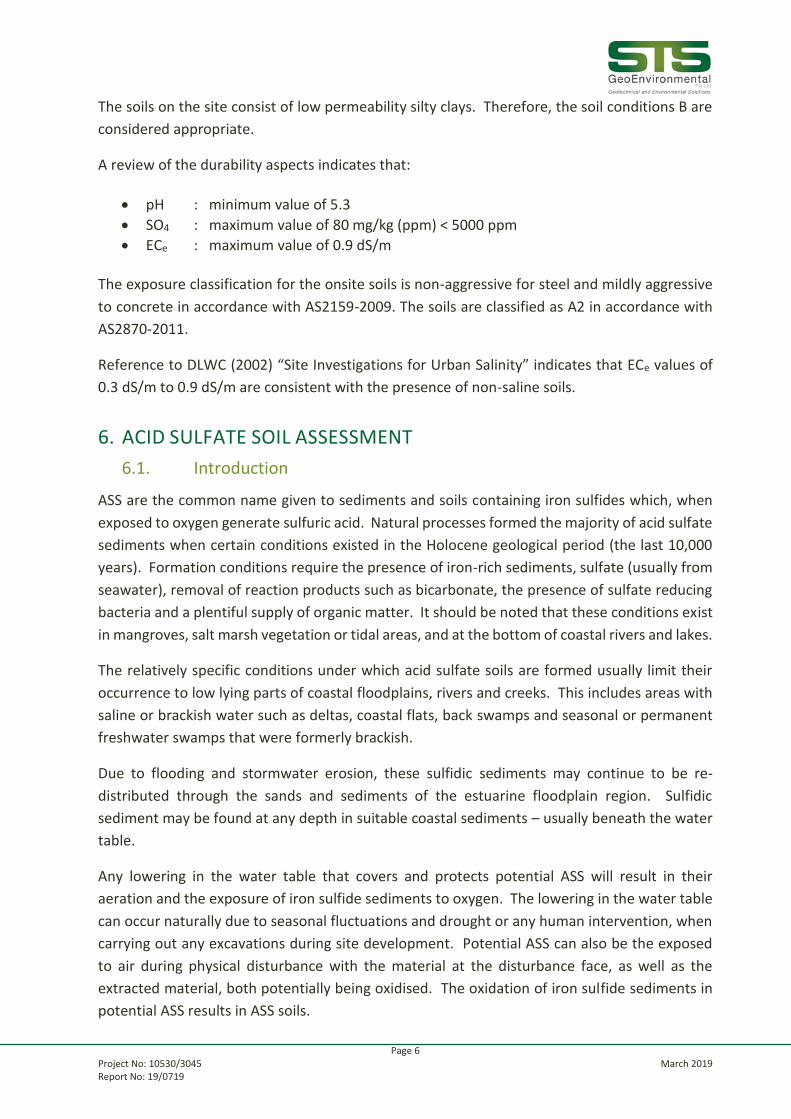
ASS are the common name given to sediments and soils containing iron sulfides which, when
exposed to oxygen generate sulfuric acid. Natural processes formed the majority of acid sulfate
sediments when certain conditions existed in the Holocene geological period (the last 10,000
years). Formation conditions require the presence of iron-rich sediments, sulfate (usually from
seawater), removal of reaction products such as bicarbonate, the presence of sulfate reducing
bacteria and a plentiful supply of organic matter. It should be noted that these conditions exist
in mangroves, salt marsh vegetation or tidal areas, and at the bottom of coastal rivers and lakes.
The relatively specific conditions under which acid sulfate soils are formed usually limit their
occurrence to low lying parts of coastal floodplains, rivers and creeks. This includes areas with
saline or brackish water such as deltas, coastal flats, back swamps and seasonal or permanent
freshwater swamps that were formerly brackish.
Due to flooding and stormwater erosion, these sulfidic sediments may continue to be re-
distributed through the sands and sediments of the estuarine floodplain region. Sulfidic
sediment may be found at any depth in suitable coastal sediments – usually beneath the water
table.
Any lowering in the water table that covers and protects potential ASS will result in their
aeration and the exposure of iron sulfide sediments to oxygen. The lowering in the water table
can occur naturally due to seasonal fluctuations and drought or any human intervention, when
carrying out any excavations during site development. Potential ASS can also be the exposed
to air during physical disturbance with the material at the disturbance face, as well as the
extracted material, both potentially being oxidised. The oxidation of iron sulfide sediments in
potential ASS results in ASS soils.

Page 7 Project No: 10530/3045 March 2019 Report No: 19/0719
Successful management of areas with ASS is possible but must take into account the specific
nature of the site and the environmental consequences of development. While it is preferable
that sites exhibiting acid sulfate characteristics not be disturbed, management techniques have
been devised to minimise and manage impacts in certain circumstances.
When works involving the disturbance of soil or the change of groundwater levels are proposed
in coastal areas, a preliminary assessment should be undertaken to determine whether acid
sulfate soils are present and if the proposed works are likely to disturb these soils.
6.2. Presence of ASS
Reference to the Beresfield ASS Risk Map indicates the property is within an area where there
are no known occurrences of Acid Sulfate Soils. It should be noted that maps are a guide only.
The following geomorphic or site criteria are normally used to determine if acid sulfate soils are
likely to be present:
• sediments of recent geological age (Holocene)
• soil horizons less than 5 in AHD
• marine or estuarine sediments and tidal lakes
• in coastal wetlands or back swamp areas
6.3. Assessment
In order to assess the significance of the ASS potential, the laboratory results carried out were
compared to action criteria contained in ASSM (1998) summarised in Table 6.1. The action
criteria trigger the need to prepare an ASSMP and are based on the percentage of oxidisable
sulphur (or equivalent TPA and TSA) for broad categories of soil types. Works in soils that exceed
these action criteria must prepare a management plan and obtain development consent.
As the soils encountered on the site primarily consisted of clays, the fine texture grade criteria
are the most appropriate and have been adopted for this assessment.

Page 8 Project No: 10530/3045 March 2019 Report No: 19/0719
Table 6.1 – ASS Action Criteria
Type of material Action Criteria if 1-1000 tonnes ASS disturbed
Action Criteria if more than 1000 tonnes ASS disturbed
Texture Range
(McDonald et al 1990)
Approx. clay content
(%<0.02mm)
Sulphur Trail %S
oxidisable (oven dry basis) eg STOS or
SPOS
Acid Trail Mol
H+/tonne (oven dry basis) eg
TPA or TSAS
Sulphur Trail %S
oxidisable (oven dry basis) eg
STOS or SPOS
Acid Trail Mol H+/tonne (oven dry
basis) eg TPA or TSAS
Coarse Texture
(CT) Sands to loamy
sands
>5
0.03 18 0.03 18
Medium Texture
(MT) Sandy loams to
light clays
5-50 0.06 36 0.03 18
Fine Texture (FT) Medium to heavy clays
and silty clays
>40
0.1 62 0.03 18
The laboratory test results are summarised in relation to the action criteria in Table 6.2.
Table 6.2 – SPOCAS TEST RESULTS SUMMARY
Analysis Unit LOR ASS1 BH1 @ 0.5m
ASS2 BH1 @ 0.7m
ASS3 BH2 @ 0.7m
Action Criteria1
<1000 tonnes disturbed
pH before Oxidation
NA 0.1 5.1 4.1 4.5 -
pH after Oxidation
NA 0.1 4.1 4.0 4.0 <3 (high risk)
S (POS) % 0.02 <0.02 <0.02 0.022 0.1
TPA mole/tonne 2 18 118 90 62
TSA Mole/tonne 2 5 44 49 62
1 = ASSMAC (1998)
= Action Criteria Exceeded

Page 9 Project No: 10530/3045 March 2019 Report No: 19/0719
The results of the soil sample analyses are compared to the above criteria in Table A, and the
analytical laboratory reports for the testing performed are provided in Appendix B.
The results show that the peroxide oxidisable sulfur (POS) percentages and titratable sulfidic
acidity (TSA) concentrations are less than the action criteria value. The titratable peroxide
acidity (TPA) concentrations measured in some of the samples are above the ‘Acid Trail’
criterion of 62 mol H+/tonne. Because the “Sulfur Trail” is below the detection limit, the “acid
trail” recorded in this samples is due to something other than sulfur which means that ASS is
not present.
Based on the above an ASS Management Plan will not be required provided onsite dewatering
does not lower the groundwater level outside the site.
7. FINAL COMMENTS
During construction, should the subsurface conditions vary from those inferred above, we
would be contacted to determine if any changes should be made to our recommendations.
The exposed bearing surfaces for footings should be inspected by a geotechnical engineer to
ensure the allowable pressure given has been achieved.
Matt Green
Senior Engineering Geologist

STS GEOENVIRONMENTAL Pty. Ltd. Scale: Unknown Date: March 2019
Client: NSW LAND & HOUSING CORPORATION
SITE INVESTIGATION 15-19 FIELDSEND STREET, EAST MAITLAND BOREHOLE AND PENETROMETER LOCATIONS
Project No. 10530/3045
Drawing No: 1\9/0719
BH5 P5
BH4 P4
BH3 P3
BH2 P2
BH1 P1
T2
T1 T4
T3

NOTES RELATING TO GEOTECHNICAL REPORTS
Introduction
These notes have been provided to outline the
methodology and limitations inherent in
geotechnical reporting. The issues discussed are
not relevant to all reports and further advice
should be sought if there are any queries
regarding any advice or report.
When copies of reports are made, they should be
reproduced in full.
Geotechnical Reports
Geotechnical reports are prepared by qualified
personnel on the information supplied or
obtained and are based on current engineering
standards of interpretation and analysis.
Information may be gained from limited
subsurface testing, surface observations, previous
work and is supplemented by knowledge of the
local geology and experience of the range of
properties that may be exhibited by the materials
present. For this reason, geotechnical reports
should be regarded as interpretative rather than
factual documents, limited to some extent by the
scope of information on which they rely.
Where the report has been prepared for a specific
purpose (eg. design of a three-storey building),
the information and interpretation may not be
appropriate if the design is changed (eg. a twenty
storey building). In such cases, the report and the
sufficiency of the existing work should be
reviewed by STS GeoEnvironmental Pty Limited
in the light of the new proposal.
Every care is taken with the report content,
however, it is not always possible to anticipate or
assume responsibility for the following
conditions:
• Unexpected variations in ground conditions.
The potential for this depends on the amount
of investigative work undertaken.
• Changes in policy or interpretation by
statutory authorities.
• The actions of contractors responding to
commercial pressures.
If these occur, STS GeoEnvironmental Pty
Limited would be pleased to resolve the matter
through further investigation, analysis or advice.
Unforeseen Conditions
Should conditions encountered on site differ
markedly from those anticipated from the
information contained in the report, STS
GeoEnvironmental Pty Limited should be
notified immediately. Early identification of site
anomalies generally results in any problems
being more readily resolved and allows re-
interpretation and assessment of the implications
for future work.
Subsurface Information
Logs of a borehole, recovered core, test pit,
excavated face or cone penetration test are an
engineering and/or geological interpretation of
the subsurface conditions. The reliability of the
logged information depends on the
drilling/testing method, sampling and/or
observation spacings and the ground conditions.
It is not always possible or economic to obtain
continuous high quality data. It should also be
recognised that the volume or material observed
or tested is only a fraction of the total subsurface
profile.
Interpretation of subsurface information and
application to design and construction must take
into consideration the spacing of the test
locations, the frequency of observations and
testing, and the possibility that geological
boundaries may vary between observation points.
Groundwater observations and measurements
outside of specially designed and constructed
piezometers should be treated with care for the
following reasons:
• In low permeability soils groundwater may
not seep into an excavation or bore in the
short time it is left open.
• A localised perched water table may not
represent the true water table.
• Groundwater levels vary according to
rainfall events or season.
• Some drilling and testing procedures mask or
prevent groundwater inflow.
The installation of piezometers and long term
monitoring of groundwater levels may be
required to adequately identify groundwater
conditions.
Supply of Geotechnical Information or
Tendering Purposes
It is recommended tenderers are provided with as
much geological and geotechnical information
that is available and that where there are
uncertainties regarding the ground conditions,
prospective tenders should be provided with
comments discussing the range of likely
conditions in addition to the investigation data.

APPENDIX A – BOREHOLE LOGS AND EXPLANATION SHEETS

STS GeoEnvironmental Pty Ltd GEOTECHNICAL LOG - NON CORE BOREHOLE
Client: NSW Land & Housing Corporation Project: 10530/3045 BOREHOLE NO.: BH 1Project: 15-19 Fieldsend Street, East Maitland Date : March 20, 2019
Location: Refer to Drawing No. 19/0719 Logged: JK Checked By: MG Sheet 1 of 1
CONSISTENCY M
W S (cohesive soils) O
A T A S or I
T A M Y RELATIVE S
E B P DESCRIPTION OF DRILLED PRODUCT M DENSITY T
R L L B (sands and U
E E DEPTH (Soil type, colour, grain size, plasticity, minor components, observations) O gravels) R
S (m) L E
SILTY SANDY CLAY: dark grey, fine grained sand, low plasticity CL FIRM M
TOPSOIL
S1 SILTY SANDY CLAY: light grey with orange brown, fine grained sand, low plasticity CL FIRM M
@ 0.4 m
ASS1
@ 0.5 m 0.5 STIFF
SILTY CLAY: light grey with orange brown, medium to high plasticiyt, CL/CH VERY STIFF M
U50 trace of fine grained sand, trace of gravel
ASS2
@ 0.7 m WEATHERED SANDSTONE/SHALE: dark grey with light grey and orange brown, fine grained EXTREMELY LOW D
1.0 STRENGTH
AUGER REFUSAL AT 1.3 M ON WEATHERED SANDSTONE/SHALE
1.5
2.0
2.5
D - disturbed sample U - undisturbed tube sample B - bulk sample Contractor: STS
WT - level of water table or free water N - Standard Penetration Test (SPT) Equipment: Edson RP70
S - jar sample Hole Diameter (mm): 100
NOTES: See explanation sheets for meaning of all descriptive terms and symbols Angle from Vertical (o): 0
Drill Bit: Spiral
Form I1 Date of Issue 16/03/17 Revision 7

STS GeoEnvironmental Pty Ltd GEOTECHNICAL LOG - NON CORE BOREHOLE
Client: NSW Land & Housing Corporation Project: 10530/3045 BOREHOLE NO.: BH 2Project: 15-19 Fieldsend Street, East Maitland Date : March 20, 2019
Location: Refer to Drawing No. 19/0719 Logged: JK Checked By: MG Sheet 1 of 1
CONSISTENCY M
W S (cohesive soils) O
A T A S or I
T A M Y RELATIVE S
E B P DESCRIPTION OF DRILLED PRODUCT M DENSITY T
R L L B (sands and U
E E DEPTH (Soil type, colour, grain size, plasticity, minor components, observations) O gravels) R
S (m) L E
SILTY SANDY CLAY: dark brown./grey, fine grained sand, low plasticity, CL FIRM M
trace of gravel
FILL
ASS3 0.5
@ 0.7 m SILTY CLAY: orange brown with light grey, medium to high plasticity CL/CH FIRM TO STIFF M
U50
STIFF
1.0
VERY STIFF
1.5
SILTY CLAY: light grey with orange brown, medium to high plasticity CL/CH VERY STIFF M
WEATHERED SANDSTONE/SHALE: light grey with dark grey, fine grained EXTREMELY LOW D
STRENGTH
2.0
2.5
BOREHOLE DISCONTINUED AT 3.0 M ON WEATHERED SANDSTONE/SHALE
D - disturbed sample U - undisturbed tube sample B - bulk sample Contractor: STS
WT - level of water table or free water N - Standard Penetration Test (SPT) Equipment: Edson RP70
S - jar sample Hole Diameter (mm): 100
NOTES: See explanation sheets for meaning of all descriptive terms and symbols Angle from Vertical (o): 0
Drill Bit: Spiral
Form I1 Date of Issue 16/03/17 Revision 7

STS GeoEnvironmental Pty Ltd GEOTECHNICAL LOG - NON CORE BOREHOLE
Client: NSW Land & Housing Corporation Project: 10530/3045 BOREHOLE NO.: BH 3Project: 15-19 Fieldsend Street, East Maitland Date : March 20, 2019
Location: Refer to Drawing No. 19/0719 Logged: JK Checked By: MG Sheet 1 of 1
CONSISTENCY M
W S (cohesive soils) O
A T A S or I
T A M Y RELATIVE S
E B P DESCRIPTION OF DRILLED PRODUCT M DENSITY T
R L L B (sands and U
E E DEPTH (Soil type, colour, grain size, plasticity, minor components, observations) O gravels) R
S (m) L E
SILTY SANDY CLAY: dark brown, fine grained sand, low plasticity CL FIRM M-VM
TOPSOIL/FILL
SILTY SANDY CLAY: light grey with orange brown, fine grained sand, low plasticity CL FIRM TO STIFF M
0.5
SILTY CLAY: orange brown with light grey, medium to high plasticity CL/CH STIFF TO M
VERY STIFF
1.0
WEATHERED SANDSTONE/SHALE: light grey with dark grey and orange brown, EXTREMELY LOW D
fine grained, clay seams STRENGTH
1.5
AUGER REFUSAL AT 1.5 M ON WEATHERED SANDSTONE/SHALE
2.0
2.5
D - disturbed sample U - undisturbed tube sample B - bulk sample Contractor: STS
WT - level of water table or free water N - Standard Penetration Test (SPT) Equipment: Edson RP70
S - jar sample Hole Diameter (mm): 100
NOTES: See explanation sheets for meaning of all descriptive terms and symbols Angle from Vertical (o): 0
Drill Bit: Spiral
Form I1 Date of Issue 16/03/17 Revision 7

STS GeoEnvironmental Pty Ltd GEOTECHNICAL LOG - NON CORE BOREHOLE
Client: NSW Land & Housing Corporation Project: 10530/3045 BOREHOLE NO.: BH 4Project: 15-19 Fieldsend Street, East Maitland Date : March 20, 2019
Location: Refer to Drawing No. 19/0719 Logged: JK Checked By: MG Sheet 1 of 1
CONSISTENCY M
W S (cohesive soils) O
A T A S or I
T A M Y RELATIVE S
E B P DESCRIPTION OF DRILLED PRODUCT M DENSITY T
R L L B (sands and U
E E DEPTH (Soil type, colour, grain size, plasticity, minor components, observations) O gravels) R
S (m) L E
SILTY CLAY: dark brown, low plasticity CL FIRM D
TOPSOIL
S2 SILTY CLAY: orange brown with light grey, medium to high plasticity CL/CH FIRM TO STIFF D-M
@ 0.4 m
0.5
U50 SILTY CLAY: light grey with orange brown, medium to high plasticity CL/CH STIFF M
1.0
WEATHERED SANDSTONE/SHALE: light grey with orange brown, fine grained EXTREMELY LOW D
STRENGTH
AUGER REFUSAL AT 1.4 M ON WEATHERED SANDSTONE/SHALE
1.5
2.0
2.5
D - disturbed sample U - undisturbed tube sample B - bulk sample Contractor: STS
WT - level of water table or free water N - Standard Penetration Test (SPT) Equipment: Edson RP70
S - jar sample Hole Diameter (mm): 100
NOTES: See explanation sheets for meaning of all descriptive terms and symbols Angle from Vertical (o): 0
Drill Bit: Spiral
Form I1 Date of Issue 16/03/17 Revision 7

STS GeoEnvironmental Pty Ltd GEOTECHNICAL LOG - NON CORE BOREHOLE
Client: NSW Land & Housing Corporation Project: 10530/3045 BOREHOLE NO.: BH 5Project: 15-19 Fieldsend Street, East Maitland Date : March 20, 2019
Location: Refer to Drawing No. 19/0719 Logged: JK Checked By: MG Sheet 1 of 1
CONSISTENCY M
W S (cohesive soils) O
A T A S or I
T A M Y RELATIVE S
E B P DESCRIPTION OF DRILLED PRODUCT M DENSITY T
R L L B (sands and U
E E DEPTH (Soil type, colour, grain size, plasticity, minor components, observations) O gravels) R
S (m) L E
SILTY SANDY CLAY: dark brown, fine grained sand, low plasticity CL FIRM M
TOPSOIL
S3 SILTY SANDY CLAY: light grey with orange brown, fine grained sand, low plasticity CL FIRM TO STIFF M
@ 0.3 m
0.5 STIFF
SILTY CLAY: orange brown with light grey, medium to high plasticity, CL/CH STIFF M
trace of sandstone and shale gravel
HAND AUGER REFUSAL AT 0.7 M STIFF
VERY STIFF
1.0
1.5
2.0
2.5
D - disturbed sample U - undisturbed tube sample B - bulk sample Contractor: STS
WT - level of water table or free water N - Standard Penetration Test (SPT) Equipment: Hand Auger
S - jar sample Hole Diameter (mm): 100
NOTES: See explanation sheets for meaning of all descriptive terms and symbols Angle from Vertical (o): 0
Drill Bit: Spiral
Form I1 Date of Issue 16/03/17 Revision 7

SMEC Testing Services Pty Ltd
14/1 Cowpasture Place, Wetherill Park NSW 2164
Phone: (02)9756 2166 Fax: (02)9756 1137 Email: [email protected]
Dynamic Cone Penetrometer Test ReportProject: 15-19 FIELDSEND STREET, EAST MAITLAND Project No.: 10530/3045
Client: NSW LAND & HOUSING CORPORATION Report No.: 19/0719
Address: Locked Bag 5112, Parramatta Report Date: 22/3/2019
Test Method: AS 1289.6.3.2 Page: 1 of 1
Site No. P1 P2 P3 P4 P5
Location
Refer to
Drawing No.
19/0719
Refer to
Drawing No.
19/0719
Refer to
Drawing No.
19/0719
Refer to
Drawing No.
19/0719
Refer to
Drawing No.
19/0719
Starting Level Surface Level Surface Level Surface Level Surface Level Surface Level
Depth (m)
0.00 - 0.15 1 2 1 1 1
0.15 - 0.30 2 3 2 4 3
0.30 - 0.45 2 2 3 5 2
0.45 - 0.60 5 4 3 7 5
0.60 - 0.75 10 4 5 7 8
0.75 - 0.90 22 7 7 8 12
0.90 - 1.05 Refusal 8 22 22 22
1.05 - 1.20 10 Refusal Refusal Refusal
1.20 - 1.35 9
1.35 - 1.50 22
1.50 - 1.65 Refusal
1.65 - 1.80
1.80 - 1.95
1.95 - 2.10
2.10 - 2.25
2.25 - 2.40
2.40 - 2.55
2.55 - 2.70
2.70 - 2.85
2.85 - 3.00
3.00 - 3.15
3.15 - 3.30
3.30 - 3.45
3.45 - 3.60
3.60 - 3.75
Remarks: * Pre drilled prior to testing
Approved Signatory...................................................................
Technician: JK Laurie Ihnativ - Manager
Penetration Resistance (blows / 150mm)
Form: RPS26 Date of Issue: 31/01/19 Revision: 7

STS GeoEnvironmental Pty Ltd
14/1 Cowpasture Place, Wetherill Park NSW 2164
Phone: (02)9756 2166 Fax: (02)9756 1137 Email: [email protected]
Tree Heights and Type
Project: 15-19 Fieldsend Street, East Maitland Project No. / STS No.: 10530/3045
Client: NSW Land & Housing Corporation Technician: JK
Canopy RadiusDistance from Tree
Along GroundHeight of Tree Native
(m) (m) (m) ( Y / N )
T1 7 L 10 N M
T2 4 L 10 N M
T3 8 U 20 Y M
T4 3 L 7 Y M
Growing / MatureTree No. Uphill / Level / Downhill
Form: RPS91 Date of Issue:28/05/07 Revision:1

E1. CLASSIFICATION OF SOILS
E1.1 Soil Classification and the Unified
System
An assessment of the site conditions usually includes an
appraisal of the data available by combining values of
engineering properties obtained by the site investigation
with descriptions, from visual observation of the materials
present on site.
The system used by SMEC in the identification of soil is
the Unified Soil Classification system (USC) which was
developed by the US Army Corps of Engineers during
World War II and has since gained international
acceptance and has been adopted in its metricated form by
the Standards Association of Australia.
The Australian Site Investigation Code (AS1726-1981,
Appendix D) recommends that the description of a soil
includes the USC group symbols which are an integral
component of the system.
The soil description should contain the following
information in order:
Soil composition
• SOIL NAME and USC classification symbol (IN
BLOCK LETTERS)
• plasticity or particle characteristics
• colour
• secondary and minor constituents (name estimated
proportion, plasticity or particle characteristics, colour
Soil condition
• moisture condition
• consistency or density index
Soil structure
• structure (zoning, defects, cementing)
Soil origin
interpretation based on observation eg FILL, TOPSOIL,
RESIDUAL, ALLUVIUM.
E1.2 Soil Composition
(a) Soil Name and Classification
Symbol
The USC system is summarised in Figure E1.2.1. The
primary division separates soil types on the basis of
particle size into:
• Coarse grained soils - more than 50% of the
material less than 60 mm is
larger than 0.06 mm (60 µm).
• Fine grained soils - more than 50% of the material
less than 60 mm is smaller than
0.06 mm (60 µm).
Initial classification is by particle size as shown in Table
E1.2.1. Further classification of fine grained soils is
based on plasticity.
TABLE E1.2.1 - CLASSIFICATION BY PARTICLE SIZE
NAME SUB-DIVISION SIZE
Clay (1)
< 2 µm
Silt (2)
2 µm to 60 µm
Sand Fine
Medium
Coarse
60 µm to 200 µm
200 µm to 600 µm
600 µm to 2 mm
Gravel (3)
Fine
Medium
Coarse
2 mm to 6 mm
6 mm to 20 mm
20 mm to 60 mm
Cobbles (3)
60 mm to 200 mm
Boulders (3) > 200 mm
Where a soil contains an appropriate amount of secondary
material, the name includes each of the secondary
components (greater than 12%) in increasing order of
significance, eg sandy silty clay.
Minor components of a soil are included in the description
by means of the terms “some” and “trace” as defined in
Table E1.2.2.
TABLE E1.2.2 - MINOR SOIL COMPONENTS
TERM DESCRIPTION APPROXIMATE
PROPORTION (%)
Trace
presence just
detectable, little or no
influence on soil
properties
0-5
Some
presence easily
detectable, little
influence on soil
properties
5-12
The USC group symbols should be included with each soil
description as shown in Table E1.2.3
TABLE E1.2.3 - SOIL GROUP SYMBOLS
SOIL TYPE PREFIX
Gravel G
Sand S
Silt M
Clay C
Organic O
Peat Pt
The group symbols are combined with qualifiers which
indicate grading, plasticity or secondary components as
shown on Table E1.2.4

TABLE E1.2.4 - SOIL GROUP QUALIFIERS
SUBGROUP SUFFIX
Well graded W
Poorly Graded P
Silty M
Clayey C
Liquid Limit <50% - low to medium plasticity L
Liquid Limit >50% - medium to high plasticity H
(b) Grading
“Well graded” Good representation of all
particle sizes from the largest
to the smallest.
“Poorly graded” One or more intermediate
sizes poorly represented
“Gap graded” One or more intermediate
sizes absent
“Uniformly graded” Essentially single size
material.
(c) Particle shape and texture
The shape and surface texture of the coarse grained
particles should be described.
Angularity may be expressed as “rounded”, “sub-
rounded”, “sub-angular” or “angular”.
Particle form can be “equidimensional”, “flat” or
elongate”.
Surface texture can be “glassy”, “smooth”, “rough”,
pitted” or striated”.
(d) Colour
The colour of the soil should be described in the moist
condition using simple terms such as:
Black White Grey Red
Brown Orange Yellow Green
Blue
These may be modified as necessary by “light” or “dark”.
Borderline colours may be described as a combination of
two colours, eg red-brown.
For soils that contain more than one colour terms such as:
• Speckled Very small (<10 mm dia) patches
• Mottled Irregular
• Blotched Large irregular (>75 mm dia)
• Streaked Randomly oriented streaks
(e) Minor Components
Secondary and minor components should be individually
described in a similar manner to the dominant component.
E1.3 Soil Condition
(a) Moisture
Soil moisture condition is described as “dry”, “moist” or
“wet”.
The moisture categories are defined as:
Dry (D) - Little or no moisture evident. Soils are running.
Moist (M) - Darkened in colour with cool feel. Granular
soil particles tend to adhere. No free water evident upon
remoulding of cohesive soils.
In addition the moisture content of cohesive soils can be
estimated in relation to their liquid or plastic limit.
(b) Consistency
Estimates of the consistency of a clay or silt soil may be
made from manual examination, hand penetrometer test,
SPT results or from laboratory tests to determine undrained
shear or unconfined compressive strengths. The
classification of consistency is defined in Table E1.3.1.
TABLE E1.3.1 - CONSISTENCY OF FINE-GRAINED
SOILS
TERM UNCONFINED
STRENGTH
(kPa)
FIELD
IDENTIFICATION
Very
Soft
<25
Easily penetrated by fist.
Sample exudes between
fingers when squeezed in
the fist.
Soft
25 - 50
Easily moulded in fingers.
Easily penetrated 50 mm by
thumb.
Firm
50 - 100
Can be moulded by strong
pressure in the fingers.
Penetrated only with great
effort.
Stiff
100 - 200
Cannot be moulded in
fingers. Indented by thumb
but penetrated only with
great effort.
Very
Stiff
200 - 400
Very tough. Difficult to cut
with knife. Readily
indented with thumb nail.
Hard
>400
Brittle, can just be scratched
with thumb nail. Tends to
break into fragments.
Unconfined compressive strength as derived by a hand
penetrometer can be taken as approximately double the
undrained shear strength (qu = 2 cu).
(c) Density Index
The insitu density index of granular soils can be assessed
from the results of SPT or cone penetrometer tests.
Density index should not be estimated visually.

TABLE E1.3.2 - DENSITY OF GRANULAR SOILS
TERM SPT N
VALUE
STATIC
CONE
VALUE
qc (MPa)
DENSITY
INDEX
(%)
Very Loose 0 - 3 0 - 2 0 - 15
Loose 3 - 8 2 - 5 15 - 35
Medium Dense 8 - 25 5 - 15 35 - 65
Dense 25 - 42 15 - 20 65 - 85
Very Dense >42 >20 >85
E1.4 Soil Structure
(a) Zoning
A sample may consist of several zones differing in colour,
grain size or other properties. Terms to classify these
zones are:
Layer - continuous across exposure or sample
Lens - discontinuous with lenticular shape
Pocket - irregular inclusion
Each zone should be described, their distinguishing
features, and the nature of the interzone boundaries.
(b) Defects
Defects which are present in the sample can include:
• fissures
• roots (containing organic matter)
• tubes (hollow)
• casts (infilled)
Defects should be described giving details of dimensions
and frequency. Fissure orientation, planarity, surface
condition and infilling should be noted. If there is a
tendency to break into blocks, block dimensions should be
recorded
E1.5 Soil Origin
Information which may be interpretative but which may
contribute to the usefulness of the material description
should be included. The most common interpreted feature
is the origin of the soil. The assessment of the probable
origin is based on the soil material description, soil
structure and its relationship to other soil and rock
materials.
Common terms used are:
“Residual Soil” - Material which appears to have been
derived by weathering from the underlying rock. There is
no evidence of transport.
“Colluvium” - Material which appears to have been
transported from its original location. The method of
movement is usually the combination of gravity and
erosion.
“Landslide Debris” - An extreme form of colluvium where
the soil has been transported by mass movement. The
material is obviously distributed and contains distinct
defects related to the slope failure.
“Alluvium” - Material which has been transported
essentially by water. usually associated with former stream
activity.
“Fill” - Material which has been transported and placed by
man. This can range from natural soils which have been
placed in a controlled manner in engineering construction
to dumped waste material. A description of the
constituents should include an assessment of the method of
placement.
E1.6 Fine Grained Soils
The physical properties of fine grained soils are dominated
by silts and clays.
The definition of clay and silt soils is governed by their
Atterberg Limits. Clay soils are characterised by the
properties of cohesion and plasticity with cohesion defines
as the ability to deform without rupture. Silts exhibit
cohesion but have low plasticity or are non-plastic.
The field characteristics of clay soils include:
• dry lumps have appreciable dry strength and cannot be
powdered
• volume changes occur with moisture content variation
• feels smooth when moist with a greasy appearance
when cut.
The field characteristics of silt soils include:
• dry lumps have negligible dry strength and can be
powdered easily
• dilatancy - an increase in volume due to shearing - is
indicted by the presence of a shiny film of water after
a hand sample is shaken. The water disappears upon
remoulding. Very fine grained sands may also exhibit
dilatancy.
• low plasticity index
• feels gritty to the teeth
E1.7 Organic Soils
Organic soils are distinguished from other soils by their
appreciable content of vegetable matter, usually derived
from plant remains.
The soil usually has a distinctive smell and low bulk
density.
The USC system uses the symbol Pt for partly decomposed
organic material. The O symbol is combined with suffixes
“O” or “H” depending on plasticity.
Where roots or root fibres are present their frequency and
the depth to which they are encountered should be
recorded. The presence of roots or root fibres does not
necessarily mean the material is an “organic material” by
classification.
Coal and lignite should be described as such and not
simply as organic matter.

APPENDIX B – LABORATORY TEST RESULTS

SMEC Testing Services Pty Ltd14/1 Cowpasture Place, Wetherill Park NSW 2164
Phone: (02)9756 2166 Fax: (02)9756 1137 Email: [email protected]
Shrink Swell Index ReportProject: 15 - 19 FIELDSENT STREET, EAST MAITLAND Project No.: 10530/1648D-L
Client: NEW SOUTH WALES LAND & HOUSING CORPERATION Report No.: 19/0747
Address: LOCKED BAG 4009, ASHFIELD Report Date: 27/03/2019
Test Method: AS 1289 7.1.1 Page: 1 OF 1
3045/1 3045/2 3045/3
Borehole 1Refer todrawing
Borehole 2Refer todrawing
Borehole 4Refer todrawing
Silty Claybrown, orangegrey, trace of
gravel
Silty Clay darkbrown, trace of
gravel
Silty Clay,orange, grey
brown, trace ofgravel
0.6 - 0.8 0.6 - 0.78 0.4 - 0.6
20/03/2019 20/03/2019 20/03/2019
Moisture Content(%)
22.8 13.4 21.9
Soil Crumbling NIL NIL NIL
Extent ofCracking
Open Cracks Open Cracks NIL
Strain (%) 3.8 1.0 1.0
Moisture ContentInitial (%)
20.5 11.7 22.3
Moisture ContentFinal (%)
29.7 18.2 27.8
Strain (%) 5.5 0.0 0.0
<5 <5 <5
3.6 0.6 0.6
Remarks:
Approved Signatory....................................................................
Technician: NP Orlando Mendoza - Laboratory Manager
Sampling Procedure: AS 1289.1.3.1 Clause 3.1.3.2 - Thin Walled Sampler
Sh
rin
kS
we
ll
Inert Inclusions (%)
Shrink Swell Index (%)
Sample Date
STS / Sample No.
Sample Location
Depth (m)
Material Description
Form: RPS41 Date of Issue: 04/02/19 Revision: 6

0 0.00 True
Environmental
CERTIFICATE OF ANALYSISWork Order : Page : 1 of 8ES1908994
:: LaboratoryClient SMEC TESTING SERVICES PTY LTD Environmental Division Sydney
: :ContactContact ALL REPORTS (ENQUIRIES) Customer Services ES
:: AddressAddress P O BOX 6989
WETHERILL PARK NSW, AUSTRALIA 2164
277-289 Woodpark Road Smithfield NSW Australia 2164
:Telephone ---- :Telephone +61-2-8784 8555
:Project 19161 19710 22426 Date Samples Received : 25-Mar-2019 10:45
:Order number E-2019-105 Date Analysis Commenced : 26-Mar-2019
:C-O-C number ---- Issue Date : 28-Mar-2019 18:02
Sampler : ----
Site : ----
Quote number : EN/222
25:No. of samples received
25:No. of samples analysed
This report supersedes any previous report(s) with this reference. Results apply to the sample(s) as submitted. This document shall not be reproduced, except in full.
This Certificate of Analysis contains the following information:
l General Comments
l Analytical Results
Additional information pertinent to this report will be found in the following separate attachments: Quality Control Report, QA/QC Compliance Assessment to assist with
Quality Review and Sample Receipt Notification.
SignatoriesThis document has been electronically signed by the authorized signatories below. Electronic signing is carried out in compliance with procedures specified in 21 CFR Part 11.
Signatories Accreditation CategoryPosition
Ankit Joshi Inorganic Chemist Sydney Inorganics, Smithfield, NSW
Ben Felgendrejeris Senior Acid Sulfate Soil Chemist Brisbane Acid Sulphate Soils, Stafford, QLD
Ivan Taylor Analyst Sydney Inorganics, Smithfield, NSW
R I G H T S O L U T I O N S | R I G H T P A R T N E R

2 of 8:Page
Work Order :
:Client
ES1908994
19161 19710 22426:Project
SMEC TESTING SERVICES PTY LTD
General Comments
The analytical procedures used by the Environmental Division have been developed from established internationally recognized procedures such as those published by the USEPA, APHA, AS and NEPM. In house
developed procedures are employed in the absence of documented standards or by client request.
Where moisture determination has been performed, results are reported on a dry weight basis.
Where a reported less than (<) result is higher than the LOR, this may be due to primary sample extract/digestate dilution and/or insufficient sample for analysis.
Where the LOR of a reported result differs from standard LOR, this may be due to high moisture content, insufficient sample (reduced weight employed) or matrix interference.
When sampling time information is not provided by the client, sampling dates are shown without a time component. In these instances, the time component has been assumed by the laboratory for processing
purposes.
Where a result is required to meet compliance limits the associated uncertainty must be considered. Refer to the ALS Contact for details.
CAS Number = CAS registry number from database maintained by Chemical Abstracts Services. The Chemical Abstracts Service is a division of the American Chemical Society.
LOR = Limit of reporting
^ = This result is computed from individual analyte detections at or above the level of reporting
ø = ALS is not NATA accredited for these tests.
~ = Indicates an estimated value.
Key :
ASS: EA029 (SPOCAS): Excess ANC not required because pH OX less than 6.5.l
ASS: EA029 (SPOCAS): Liming rate is calculated and reported on a dry weight basis assuming use of fine agricultural lime (CaCO3) and using a safety factor of 1.5 to allow for non-homogeneous mixing and poor
reactivity of lime. For conversion of Liming Rate from kg/t dry weight to kg/m3 in-situ soil, multiply reported results x wet bulk density of soil in t/m3.
l

3 of 8:Page
Work Order :
:Client
ES1908994
19161 19710 22426:Project
SMEC TESTING SERVICES PTY LTD
Analytical Results
19161/497119161/497019161/495819161/495219161/4696AClient sample IDSub-Matrix: SOIL
(Matrix: SOIL)
25-Mar-2019 00:0025-Mar-2019 00:0025-Mar-2019 00:0025-Mar-2019 00:0025-Mar-2019 00:00Client sampling date / time
ES1908994-005ES1908994-004ES1908994-003ES1908994-002ES1908994-001UnitLORCAS NumberCompound
Result Result Result Result Result
EA002: pH 1:5 (Soils)
5.7 6.7 5.5 6.5 4.8pH Unit0.1----pH Value
EA010: Conductivity (1:5)
90 222 86 27 663µS/cm1----Electrical Conductivity @ 25°C
EA055: Moisture Content (Dried @ 105-110°C)
20.5 14.1 13.4 14.6 16.9%0.1----Moisture Content
ED040S : Soluble Sulfate by ICPAES
<10Sulfate as SO4 2- 140 20 <10 100mg/kg1014808-79-8

4 of 8:Page
Work Order :
:Client
ES1908994
19161 19710 22426:Project
SMEC TESTING SERVICES PTY LTD
Analytical Results
19161/498919161/498819161/498519161/497919161/4973Client sample IDSub-Matrix: SOIL
(Matrix: SOIL)
25-Mar-2019 00:0025-Mar-2019 00:0025-Mar-2019 00:0025-Mar-2019 00:0025-Mar-2019 00:00Client sampling date / time
ES1908994-010ES1908994-009ES1908994-008ES1908994-007ES1908994-006UnitLORCAS NumberCompound
Result Result Result Result Result
EA002: pH 1:5 (Soils)
6.5 6.0 6.1 7.4 5.9pH Unit0.1----pH Value
EA010: Conductivity (1:5)
171 28 39 548 280µS/cm1----Electrical Conductivity @ 25°C
EA055: Moisture Content (Dried @ 105-110°C)
16.3 8.7 5.7 9.0 12.1%0.1----Moisture Content
ED040S : Soluble Sulfate by ICPAES
110Sulfate as SO4 2- <10 <10 320 100mg/kg1014808-79-8

5 of 8:Page
Work Order :
:Client
ES1908994
19161 19710 22426:Project
SMEC TESTING SERVICES PTY LTD
Analytical Results
10530/3044/S122417/S122426/S222426/S119710/849Client sample IDSub-Matrix: SOIL
(Matrix: SOIL)
25-Mar-2019 00:0025-Mar-2019 00:0025-Mar-2019 00:0025-Mar-2019 00:0025-Mar-2019 00:00Client sampling date / time
ES1908994-015ES1908994-014ES1908994-013ES1908994-012ES1908994-011UnitLORCAS NumberCompound
Result Result Result Result Result
EA002: pH 1:5 (Soils)
6.8 8.2 8.0 6.6 6.6pH Unit0.1----pH Value
EA010: Conductivity (1:5)
47 192 309 36 46µS/cm1----Electrical Conductivity @ 25°C
EA055: Moisture Content (Dried @ 105-110°C)
19.9 17.7 13.9 23.7 25.1%0.1----Moisture Content
ED040S : Soluble Sulfate by ICPAES
20Sulfate as SO4 2- 60 260 60 10mg/kg1014808-79-8

6 of 8:Page
Work Order :
:Client
ES1908994
19161 19710 22426:Project
SMEC TESTING SERVICES PTY LTD
Analytical Results
10530/3045/S310530/3045/S210530/3045/S110530/3044/S310530/3044/S2Client sample IDSub-Matrix: SOIL
(Matrix: SOIL)
25-Mar-2019 00:0025-Mar-2019 00:0025-Mar-2019 00:0025-Mar-2019 00:0025-Mar-2019 00:00Client sampling date / time
ES1908994-020ES1908994-019ES1908994-018ES1908994-017ES1908994-016UnitLORCAS NumberCompound
Result Result Result Result Result
EA002: pH 1:5 (Soils)
7.3 5.8 6.6 5.3 6.1pH Unit0.1----pH Value
EA010: Conductivity (1:5)
79 92 28 126 40µS/cm1----Electrical Conductivity @ 25°C
EA055: Moisture Content (Dried @ 105-110°C)
19.2 21.7 11.7 17.7 14.0%0.1----Moisture Content
ED040S : Soluble Sulfate by ICPAES
10Sulfate as SO4 2- 60 40 80 40mg/kg1014808-79-8

7 of 8:Page
Work Order :
:Client
ES1908994
19161 19710 22426:Project
SMEC TESTING SERVICES PTY LTD
Analytical Results
10530/3045/S310530/3045/S210530/3045/S122430/S222430/S1Client sample IDSub-Matrix: SOIL
(Matrix: SOIL)
25-Mar-2019 00:0025-Mar-2019 00:0025-Mar-2019 00:0025-Mar-2019 00:0025-Mar-2019 00:00Client sampling date / time
ES1908994-025ES1908994-024ES1908994-023ES1908994-022ES1908994-021UnitLORCAS NumberCompound
Result Result Result Result Result
EA002: pH 1:5 (Soils)
9.7 8.5 ---- ---- ----pH Unit0.1----pH Value
EA010: Conductivity (1:5)
325 2010 ---- ---- ----µS/cm1----Electrical Conductivity @ 25°C
EA029-A: pH Measurements
---- ---- 5.1 4.1 4.5pH Unit0.1----pH KCl (23A)
---- ---- 4.1 4.0 4.0pH Unit0.1----pH OX (23B)
EA029-B: Acidity Trail
---- ---- 13 74 40mole H+ / t2----Titratable Actual Acidity (23F)
---- ---- 18 118 90mole H+ / t2----Titratable Peroxide Acidity (23G)
---- ---- 5 44 49mole H+ / t2----Titratable Sulfidic Acidity (23H)
---- ---- 0.021 0.119 0.065% pyrite S0.020----sulfidic - Titratable Actual Acidity (s-23F)
---- ---- 0.029 0.189 0.144% pyrite S0.020----sulfidic - Titratable Peroxide Acidity
(s-23G)
---- ---- <0.020 0.070 0.079% pyrite S0.020----sulfidic - Titratable Sulfidic Acidity (s-23H)
EA029-C: Sulfur Trail
---- ---- <0.020 <0.020 <0.020% S0.020----KCl Extractable Sulfur (23Ce)
---- ---- <0.020 <0.020 0.022% S0.020----Peroxide Sulfur (23De)
---- ---- <0.020 <0.020 0.022% S0.020----Peroxide Oxidisable Sulfur (23E)
---- ---- <10 <10 14mole H+ / t10----acidity - Peroxide Oxidisable Sulfur
(a-23E)
EA029-D: Calcium Values
---- ---- 0.066 0.046 0.086% Ca0.020----KCl Extractable Calcium (23Vh)
---- ---- 0.072 0.048 0.094% Ca0.020----Peroxide Calcium (23Wh)
---- ---- <0.020 <0.020 <0.020% Ca0.020----Acid Reacted Calcium (23X)
---- ---- <10 <10 <10mole H+ / t10----acidity - Acid Reacted Calcium (a-23X)
---- ---- <0.020 <0.020 <0.020% S0.020----sulfidic - Acid Reacted Calcium (s-23X)
EA029-E: Magnesium Values
---- ---- <0.020 0.074 0.048% Mg0.020----KCl Extractable Magnesium (23Sm)
---- ---- <0.020 0.076 0.053% Mg0.020----Peroxide Magnesium (23Tm)
---- ---- <0.020 <0.020 <0.020% Mg0.020----Acid Reacted Magnesium (23U)
---- ---- <10 <10 <10mole H+ / t10----Acidity - Acid Reacted Magnesium (a-23U)
---- ---- <0.020 <0.020 <0.020% S0.020----sulfidic - Acid Reacted Magnesium
(s-23U)
EA029-G: Retained Acidity

8 of 8:Page
Work Order :
:Client
ES1908994
19161 19710 22426:Project
SMEC TESTING SERVICES PTY LTD
Analytical Results
10530/3045/S310530/3045/S210530/3045/S122430/S222430/S1Client sample IDSub-Matrix: SOIL
(Matrix: SOIL)
25-Mar-2019 00:0025-Mar-2019 00:0025-Mar-2019 00:0025-Mar-2019 00:0025-Mar-2019 00:00Client sampling date / time
ES1908994-025ES1908994-024ES1908994-023ES1908994-022ES1908994-021UnitLORCAS NumberCompound
Result Result Result Result Result
EA029-G: Retained Acidity - Continued
---- ---- ---- <0.020 ----% S0.020----HCl Extractable Sulfur (20Be)
---- ---- ---- <0.020 ----% S0.020----Net Acid Soluble Sulfur (20Je)
---- ---- ---- <10 ----mole H+ / t10----acidity - Net Acid Soluble Sulfur (a-20J)
---- ---- ---- <0.020 ----% pyrite S0.020----sulfidic - Net Acid Soluble Sulfur (s-20J)
EA029-H: Acid Base Accounting
---- ---- 1.5 1.5 1.5-0.5----ANC Fineness Factor
---- ---- 0.02 0.12 0.09% S0.02----Net Acidity (sulfur units)
---- ---- 13 74 54mole H+ / t10----Net Acidity (acidity units)
---- ---- 1 6 4kg CaCO3/t1----Liming Rate
---- ---- 0.02 0.12 0.09% S0.02----Net Acidity excluding ANC (sulfur units)
---- ---- 13 74 54mole H+ / t10----Net Acidity excluding ANC (acidity units)
---- ---- 1 6 4kg CaCO3/t1----Liming Rate excluding ANC
EA055: Moisture Content (Dried @ 105-110°C)
12.3 14.7 ---- ---- ----%0.1----Moisture Content
ED040S : Soluble Sulfate by ICPAES
130Sulfate as SO4 2- 3320 ---- ---- ----mg/kg1014808-79-8
ED045G: Chloride by Discrete Analyser
570Chloride 1670 ---- ---- ----mg/kg1016887-00-6