Embed Size (px)
Citation preview
Geotechnical Engineering ReportWestern Area Power Administration
Gila-Knob T/L Rebuild, Phase 1Near Yuma, Arizona
March 2, 2016Terracon Project No. 65155124, Revision No. 1
Prepared for:Civil Design & Engineering, Inc.
Phoenix, Arizona
Prepared by:Terracon Consultants, Inc.
Tempe, Arizona

Terracon Consul tants, Inc. 4685 South Ash Avenue, Suite H-4, Tempe, Ar izona 85282P [480] 897-8200 F [480]-897-1133 terracon.com
March 2, 2016
Civil Design & Engineering, Inc.340 East Palm Lane, Suite A-138Phoenix, Arizona 85004
Attn: Christine Laguna, P.E.
Re: Geotechnical Engineering ReportWestern Area Power AdministrationGila-Knob T/L Rebuild, Phase 1Near Yuma, ArizonaTerracon Project No. 65155124, Revision No. 1
Dear Ms. Laguna:
Terracon Consultants, Inc. (Terracon) has completed the geotechnical engineering services forthe proposed Western Area Power Administration (Western) Gila-Knob T/L Rebuild, Phase 1project near Yuma, Arizona. These services were performed in general accordance with ourProposal No. P65150718 dated November 6, 2015 and subsequent Task Order No. 189. Thisgeotechnical engineering report presents the results of the subsurface exploration and providesgeotechnical engineering recommendations concerning the design and construction of deepfoundations for the planned transmission line foundations. This report has been revised toprovide additional information regarding caving potential and excavation characteristics.
We appreciate the opportunity to be of service to you on this project. If you have any questionsconcerning this report, or if we may be of further service, please contact us.
Sincerely,Terracon Consultants, Inc.
Jesse R. Huston, P.E. Donald R. Clark P.E.Senior Project Manager Senior Principal
Copies to: Addressee (1 via email)

Geotechnical Engineering ReportGila-Knob T/L Rebuild, Phase 1 ■ Near Yuma, ArizonaMarch 2, 2016 ■ Terracon Project No. 65155124, Revision No. 1
Resourceful ■ Responsive ■ Reliable
TABLE OF CONTENTSPage
EXECUTIVE SUMMARY ............................................................................................................. i1.0 INTRODUCTION .............................................................................................................12.0 PROJECT INFORMATION .............................................................................................1
2.1 Project Description ...............................................................................................12.2 Site Description ....................................................................................................2
3.0 SUBSURFACE CONDITIONS ........................................................................................23.1 Site Geology ........................................................................................................23.2 Liquefaction Potential ...........................................................................................33.3 Subsurface Soil Condtions ...................................................................................33.4 Groundwater Conditions ......................................................................................43.5 Seismic Considerations........................................................................................4
4.0 RECOMMENDATIONS FOR DESIGN AND CONSTRUCTION ......................................54.1 Geotechnical Considerations ...............................................................................54.2 Drilled Shaft Foundations .....................................................................................6
4.2.1 Axial Loading Design Criteria....................................................................64.2.2 Lateral Loading Design Criteria ................................................................74.2.3 Drilled Shaft Construction Considerations.................................................9
4.3 Corrosion Considerations .....................................................................................95.0 GENERAL COMMENTS ...............................................................................................10
Exhibit No.Appendix A – Field Exploration
Site Plan and Test Locations ....................................................................................... A-1Field Exploration Description ....................................................................................... A-2General Notes ............................................................................................................. A-3Unified Soil Classification System ................................................................................ A-4Boring Logs .................................................................................................... A-5 thru A-8
Appendix B – Laboratory TestingLaboratory Test Description ......................................................................................... B-1Atterberg Limits Results............................................................................................... B-2Grain Size Distribution ................................................................................................. B-3Direct Shear Test Results ............................................................................... B-4 thru B-7Unconfined Compression Test Results ........................................................................ B-8Summary of Laboratory Results ................................................................... B-9 thru B-10

Geotechnical Engineering ReportGila-Knob T/L Rebuild, Phase 1 ■ Near Yuma, ArizonaMarch 2, 2016 ■ Terracon Project No. 65155124, Revision No. 1
Resourceful ■ Responsive ■ Reliable
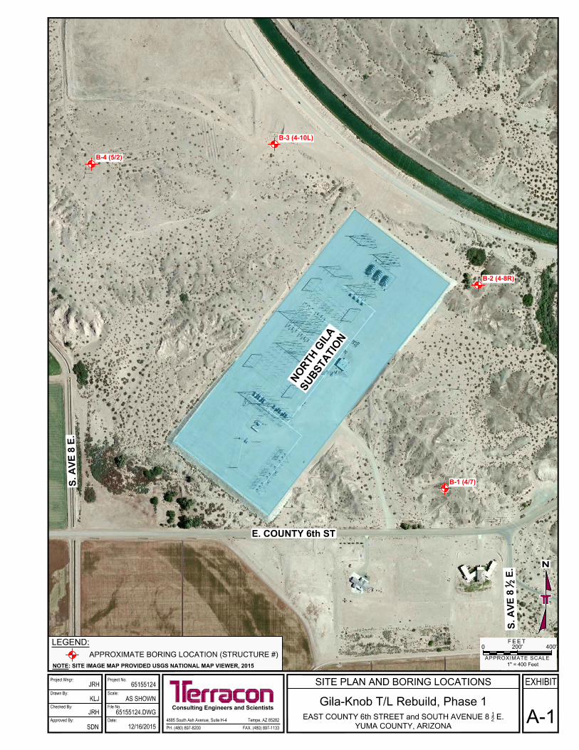
EXECUTIVE SUMMARYA geotechnical engineering exploration has been performed for the proposed Western Area PowerAdministration’s Gila-Knob T/L Rebuild, Phase 1 project located just outside of the North GilaSubstation near Yuma, Arizona. Terracon’s geotechnical scope of work included the advancementof four (4) test borings to an approximate depth 40 feet below existing site grades, laboratorytesting on representative samples of the subsurface materials, engineering analyses anddevelopment of engineering recommendations for design and construction of foundations tosupport the proposed structures.
Based on the information obtained from our engineering analyses of the field and laboratory data,the site appears suitable for the proposed construction based upon geotechnical conditionsencountered in the test borings, and provided our recommendations contained in this report areproperly implemented in the design and construction. The following geotechnical considerationswere identified:
n The subsurface conditions encountered in the test borings generally consists of sand soilswith variable amounts of silt and gravel to the maximum depth explored in Borings B-1 andB-2. In Borings B-3 and B-4 to the west of the existing substation, these upper sand soilswere underlain with fat clay starting at depths of 19 and 28 feet, respectively. The relativedensity of the sand soils was generally medium dense to very dense in Borings B-1 and B-2,and loose near the surface in Borings B-3 and B-4 increasing to medium dense below anapproximate depth of five (5) feet. The lower fat clay soils were generally very stiff to hard inconsistency.
n Groundwater was encountered in Boring B-2 (at Structure 4/8) during drilling at a depth of 32feet. Groundwater was not encountered in the remaining three (3) borings to the maximumdepth explored of approximately 40 feet. Depending upon the final foundation depths,groundwater may be encountered during construction of drilled shaft foundations,particularly for foundations located near Structure 4/8.
n We recommend that pole and truss-mounted equipment be supported on drilled shaftfoundation systems. If utilized, fully embedded steel poles should be embedded inaccordance with the pole manufacturer’s recommendations. Drilling of foundations to designdepths should be possible with conventional drilling equipment using single flight poweraugers. However, considering the sandy and dry nature of the subsurface soils above thelevel of groundwater, and the presence of relatively shallow groundwater, the cavingpotential of uncased foundations is considered to be high. Therefore, construction of drilledshaft foundations will likely necessitate the use of temporary casing and/or wet drillingmethods.
Geotechnical Engineering ReportGila-Knob T/L Rebuild, Phase 1 ■ Near Yuma, ArizonaMarch 2, 2016 ■ Terracon Project No. 65155124, Revision No. 1
Resourceful ■ Responsive ■ Reliable
n Other than drilled shaft foundation excavations, no other types of excavations areanticipated for construction of this transmission line project. In the event that other types ofexcavations may be required, it is anticipated that the excavations can be accomplished withconventional earthmoving equipment, including backhoe type equipment. It should be notedthat very dense materials were encountered below a depth of four feet in Boring B-2 andincreased excavation efforts may be necessary for excavations extending into thesematerials with backhoe type equipment.
n The Yuma area is located in a seismically active zone, and valley areas in and around Yumaare known to be susceptible to seismically induced liquefaction. As part of our engineeringevaluation, we have reviewed a liquefaction hazard potential report for Yuma, Arizona.Based on this review, the project site is not located within an area that has been mapped asbeing susceptible to liquefaction.
n The 2012 International Building Code seismic site classification for this site is Site Class D.
n Other than drilled shaft foundation excavations, no other type of excavation is anticipated forconstruction of this transmission line project. In the event that other types of excavationsmay be required, including backhoe type excavations, no particular excavation difficulty isanticipated.
This executive summary should be used in conjunction with the entire report for design and/orconstruction purposes. It should be recognized that specific details were not included or fullydeveloped in this section, and the report must be read in its entirety for a comprehensiveunderstanding of the items contained herein. The section titled General Comments should be readfor an understanding of the report limitations.

Resourceful ■ Responsive ■ Reliable
GEOTECHNICAL ENGINEERING REPORTWESTERN AREA POWER ADMINISTRATION
GILA-KNOB T/L REBUILD, PHASE 1NEAR YUMA, ARIZONA
Terracon Project No. 65155124, Revision No. 1March 2, 2016
1.0 INTRODUCTION
This report presents the results of our geotechnical engineering services performed for theproposed Western Area Power Administration’s (Western) Gila-Knob Transmission Line Rebuild,Phase 1 located around the North Gila Substation near Yuma, Arizona. The location of the site isshown on a Vicinity Map (Exhibit A-1) included in Appendix A of this report. The purpose of theseservices is to provide information and geotechnical engineering recommendations relative to:
n subsurface soil conditions n groundwater conditionsn earthwork n foundation design and constructionn seismic considerations
Our geotechnical engineering scope of work for this project included drilling four (4) borings forsubsurface exploration, laboratory testing, geotechnical engineering analysis, and preparation ofthis report. Logs of the borings along with a Site Plan and Test Locations diagram (Exhibit A-2) areincluded in Appendix A of this report. The results of the laboratory testing performed on soilsamples obtained from the site during the field exploration are included in Appendix B of this report.Descriptions of the field exploration and laboratory testing are included in their respectiveappendices.
2.0 PROJECT INFORMATION
2.1 Project Description
ITEM DESCRIPTIONSite Layout See Exhibit A-1 in Appendix A.
Structures
Western is designing three (3) 230-kV double-circuit steel monopolesand six (6) single-circuit steel H-frame structures for the Gila-Knob No. 1230-kV Transmission line to replace and upgade the existing 161-kVsingle-circuit structures.
Geotechnical Engineering ReportGila-Knob T/L Rebuild, Phase 1 ■ Near Yuma, ArizonaMarch 2, 2016 ■ Terracon Project No. 65155124, Revision No. 1
Resourceful ■ Responsive ■ Reliable 2
2.2 Site Description
ITEM DESCRIPTION
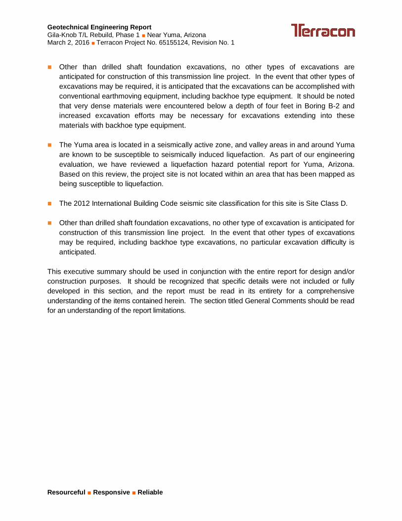
Location The project site is located at the northeast corner of E. County 6 th Streetand S. Avenue 8E near Yuma in Yuma County, Arizona.
Description The site is generally native desert consisting of sand dunes.
Existing topographyThe project site is located on a pediment slightly above the lower lyingand relatively flat Gila River Valley floodplain located to the south.
Current ground cover Bare soil with sparse desert shrubs.
3.0 SUBSURFACE CONDITIONS
3.1 Site Geology
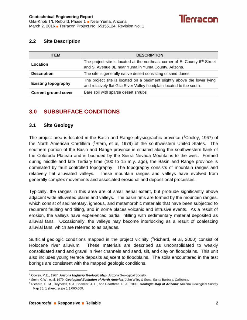
The project area is located in the Basin and Range physiographic province (1Cooley, 1967) ofthe North American Cordillera (2Stern, et al, 1979) of the southwestern United States. Thesouthern portion of the Basin and Range province is situated along the southwestern flank ofthe Colorado Plateau and is bounded by the Sierra Nevada Mountains to the west. Formedduring middle and late Tertiary time (100 to 15 m.y. ago), the Basin and Range province isdominated by fault controlled topography. The topography consists of mountain ranges andrelatively flat alluviated valleys. These mountain ranges and valleys have evolved fromgenerally complex movements and associated erosional and depositional processes.
Typically, the ranges in this area are of small aerial extent, but protrude significantly aboveadjacent wide alluviated plains and valleys. The basin rims are formed by the mountain ranges,which consist of sedimentary, igneous, and metamorphic materials that have been subjected torecurrent faulting and tilting, and in some places volcanic and intrusive events. As a result oferosion, the valleys have experienced partial infilling with sedimentary material deposited asalluvial fans. Occasionally, the valleys may become interlocking as a result of coalescingalluvial fans, which are referred to as bajadas.
Surficial geologic conditions mapped in the project vicinity (3Richard, et al, 2000) consist ofHolocene river alluvium. These materials are described as unconsolidated to weaklyconsolidated sand and gravel in river channels and sand, silt, and clay on floodplains. This unitalso includes young terrace deposits adjacent to floodplains. The soils encountered in the testborings are consistent with the mapped geologic conditions.
1 Cooley, M.E., 1967, Arizona Highway Geologic Map, Arizona Geological Society.2 Stern, C.W., et al, 1979, Geological Evolution of North America, John Wiley & Sons, Santa Barbara, California.3 Richard, S. M., Reynolds, S.J., Spencer, J. E., and Pearthree, P. A., 2000, Geologic Map of Arizona: Arizona Geological Survey
Map 35, 1 sheet, scale 1:1,000,000.
Geotechnical Engineering ReportGila-Knob T/L Rebuild, Phase 1 ■ Near Yuma, ArizonaMarch 2, 2016 ■ Terracon Project No. 65155124, Revision No. 1
Resourceful ■ Responsive ■ Reliable 3
3.2 Liquefaction Potential
The Yuma area is located in a seismically active zone, and valley areas in and around Yumaare known to be susceptible to seismically induced liquefaction. As part of our engineeringevaluation, we have reviewed a liquefaction hazard potential report for Yuma, Arizona (4Stringer,1997). Based on this review, the project site is not located within an area that has beenmapped as being susceptible to liquefaction. Additionally, considering that groundwater wasencountered in Boring B-2 only and the soils below the groundwater elevation are dense inrelative density, the potential for liquefaction of soils on this site is considered low.
3.3 Subsurface Soil Conditions
Specific conditions encountered at each boring location are indicated on the individual boring logsincluded in Appendix A of this report. Stratification boundaries on the boring logs represent theapproximate location of changes in soil types; in-situ, the transition between materials may begradual. Details for each of the borings can be found on the boring logs included in Appendix A ofthis report.
The subsurface conditions encountered in the test borings generally consists of sand soils withvariable amounts of silt and gravel to the maximum depth explored in Borings B-1 and B-2,although an upper layer of silty sandy clay was encountered at the surface in Boring B-2. InBorings B-3 and B-4 to the west of the existing substation, these upper sand soils were underlainwith fat clay starting at depths of 19 and 28 feet, respectively. The relative density of the sandsoils was generally medium dense to very dense in Borings B-1 and B-2, and loose at the surfacein Borings B-3 and B-4 increasing to medium dense below an approximate depth of five (5) feet.The lower fat clay soils were generally very stiff to hard in consistency.
Laboratory tests were conducted on selected soil samples and the test results are presented inAppendix B. The sand and sandy soils exhibit nonplastic to low plasticity characteristics. Thedeeper fat clay soils encountered in Borings B-3 and B-4 exhibit high plasticity characteristics.The moisture content of the sand soils above the groundwater elevation was generally 1 to 2percent, and about 20 percent in the fat clay soils. Saturated direct shear testing performed atin-situ dry density indicated a friction angle of 37 and cohesion of 120 psf in the sand soils withgravel, and a friction angle of and 31 degrees and apparent cohesion of 312 psf in the sandsoils without gravel. Unconfined compression testing performed on a relatively undisturbedsample of fat clay resulted in an undrained shear strength of 5.6 ksf.
4 Stringer, S.L., 1997, Liquefaction Hazard Evaluation, Yuma Arizona, Southland Geotechnical, Report No. Y97036.
Geotechnical Engineering ReportGila-Knob T/L Rebuild, Phase 1 ■ Near Yuma, ArizonaMarch 2, 2016 ■ Terracon Project No. 65155124, Revision No. 1
Resourceful ■ Responsive ■ Reliable 4
3.4 Groundwater Conditions
Groundwater was encountered in Boring B-2 (at Structure 4/8) during drilling at a depth of 32feet. Groundwater was not encountered in the remaining three (3) borings to the maximumdepth explored of approximately 40 feet. Depending upon the final foundation depths,groundwater may be encountered during construction of drilled shaft foundations, particularly forfoundations located near Structure 4/8. These observations represent groundwater conditionsat the time of the field exploration and may not be indicative of other times, or at other locations.Groundwater conditions can change with varying seasonal and weather conditions, and otherfactors.
Based on information obtained from the Arizona Department of Water Resources –Groundwater Data website (https://gisweb.azwater.gov/waterresourcedata/GWSI.aspx), thedepth to regional groundwater was measured in October 2014 to be approximately 24 feetbelow the ground surface (approximate elevation of 146 feet above mean sea level) at anArizona Department of Water Resources (ADWR) monitored well site (Local ID C-08-21 21BCA)located approximately four (4) miles east-southeast of the site.
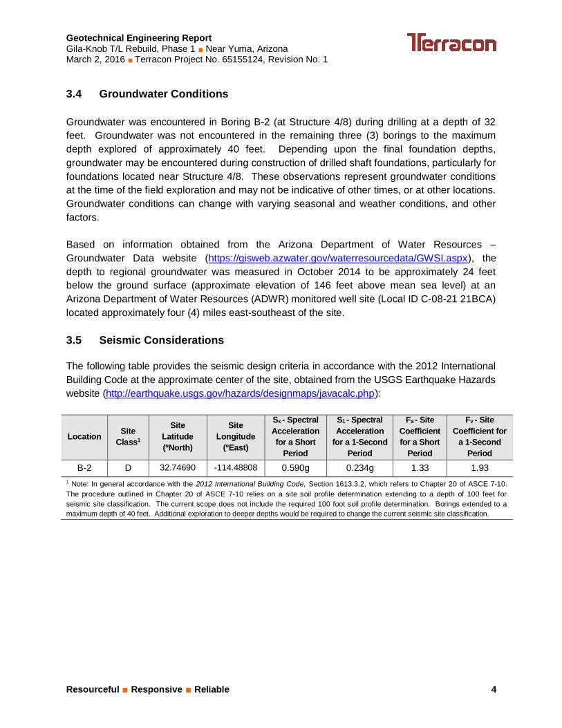
3.5 Seismic Considerations
The following table provides the seismic design criteria in accordance with the 2012 InternationalBuilding Code at the approximate center of the site, obtained from the USGS Earthquake Hazardswebsite (http://earthquake.usgs.gov/hazards/designmaps/javacalc.php):
Location SiteClass1
SiteLatitude(ºNorth)
SiteLongitude
(ºEast)
Ss - SpectralAccelerationfor a Short
Period
S1 - SpectralAcceleration
for a 1-SecondPeriod
Fa - SiteCoefficientfor a Short
Period
Fv - SiteCoefficient for
a 1-SecondPeriod
B-2 D 32.74690 -114.48808 0.590g 0.234g 1.33 1.931 Note: In general accordance with the 2012 International Building Code, Section 1613.3.2, which refers to Chapter 20 of ASCE 7-10.The procedure outlined in Chapter 20 of ASCE 7-10 relies on a site soil profile determination extending to a depth of 100 feet forseismic site classification. The current scope does not include the required 100 foot soil profile determination. Borings extended to amaximum depth of 40 feet. Additional exploration to deeper depths would be required to change the current seismic site classification.
Geotechnical Engineering ReportGila-Knob T/L Rebuild, Phase 1 ■ Near Yuma, ArizonaMarch 2, 2016 ■ Terracon Project No. 65155124, Revision No. 1
Resourceful ■ Responsive ■ Reliable 5
4.0 RECOMMENDATIONS FOR DESIGN AND CONSTRUCTION
4.1 Geotechnical Considerations
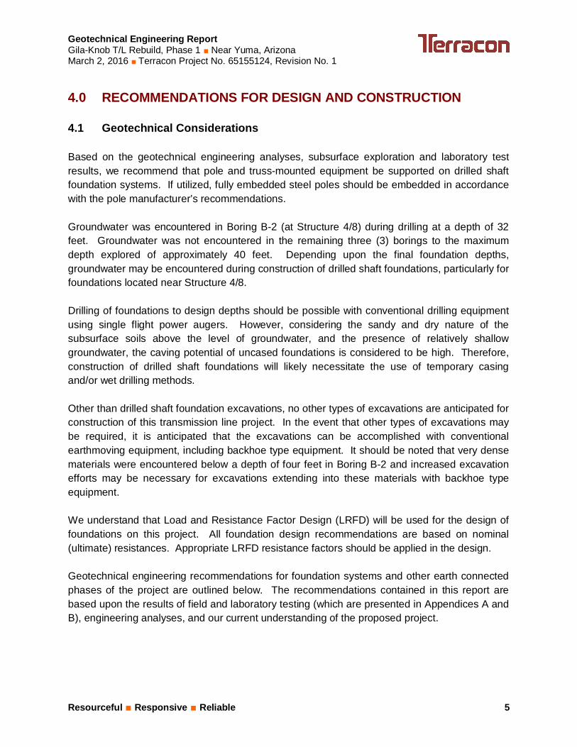
Based on the geotechnical engineering analyses, subsurface exploration and laboratory testresults, we recommend that pole and truss-mounted equipment be supported on drilled shaftfoundation systems. If utilized, fully embedded steel poles should be embedded in accordancewith the pole manufacturer’s recommendations.
Groundwater was encountered in Boring B-2 (at Structure 4/8) during drilling at a depth of 32feet. Groundwater was not encountered in the remaining three (3) borings to the maximumdepth explored of approximately 40 feet. Depending upon the final foundation depths,groundwater may be encountered during construction of drilled shaft foundations, particularly forfoundations located near Structure 4/8.
Drilling of foundations to design depths should be possible with conventional drilling equipmentusing single flight power augers. However, considering the sandy and dry nature of thesubsurface soils above the level of groundwater, and the presence of relatively shallowgroundwater, the caving potential of uncased foundations is considered to be high. Therefore,construction of drilled shaft foundations will likely necessitate the use of temporary casingand/or wet drilling methods.
Other than drilled shaft foundation excavations, no other types of excavations are anticipated forconstruction of this transmission line project. In the event that other types of excavations maybe required, it is anticipated that the excavations can be accomplished with conventionalearthmoving equipment, including backhoe type equipment. It should be noted that very densematerials were encountered below a depth of four feet in Boring B-2 and increased excavationefforts may be necessary for excavations extending into these materials with backhoe typeequipment.
We understand that Load and Resistance Factor Design (LRFD) will be used for the design offoundations on this project. All foundation design recommendations are based on nominal(ultimate) resistances. Appropriate LRFD resistance factors should be applied in the design.
Geotechnical engineering recommendations for foundation systems and other earth connectedphases of the project are outlined below. The recommendations contained in this report arebased upon the results of field and laboratory testing (which are presented in Appendices A andB), engineering analyses, and our current understanding of the proposed project.
Geotechnical Engineering ReportGila-Knob T/L Rebuild, Phase 1 ■ Near Yuma, ArizonaMarch 2, 2016 ■ Terracon Project No. 65155124, Revision No. 1
Resourceful ■ Responsive ■ Reliable 6
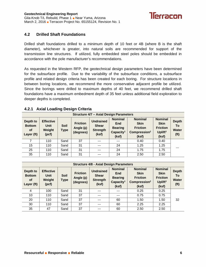
4.2 Drilled Shaft Foundations
Drilled shaft foundations drilled to a minimum depth of 10 feet or 4B (where B is the shaftdiameter), whichever is greater, into natural soils are recommended for support of thetransmission line structures. If utilized, fully embedded steel poles should be embedded inaccordance with the pole manufacturer’s recommendations.
As requested in the Western RFP, the geotechnical design parameters have been determinedfor the subsurface profile. Due to the variability of the subsurface conditions, a subsurfaceprofile and related design criteria has been created for each boring. For structure locations inbetween boring locations, we recommend the more conservative adjacent profile be utilized.Since the borings were drilled to maximum depths of 40 feet, we recommend drilled shaftfoundations have a maximum embedment depth of 35 feet unless additional field exploration todeeper depths is completed.
4.2.1 Axial Loading Design CriteriaStructure 4/7 – Axial Design Parameters
Depth toBottom
ofLayer (ft)
EffectiveUnit
Weight(pcf)
SoilType
FrictionAngle (f)(degrees)
UndrainedShear
Strength(ksf)
NominalEnd
BearingCapacity1
(ksf)
NominalSkin
FrictionCompression2
(ksf)
NominalSkin
FrictionUplift3
(ksf)
DepthTo
Water(ft)
7 110 Sand 37 --- --- 0.40 0.40
---15 110 Sand 31 --- 24 1.25 1.2525 110 Sand 31 --- 24 1.75 1.7535 110 Sand 31 --- 24 2.50 2.50
Structure 4/8 - Axial Design Parameters
Depth toBottom
ofLayer (ft)
EffectiveUnit
Weight(pcf)
SoilType
FrictionAngle (f)(degrees)
UndrainedShear
Strength (ksf)
NominalEnd
BearingCapacity1
(ksf)
NominalSkin
FrictionCompression2
(ksf)
NominalSkin
FrictionUplift3
(ksf)
DepthTo
Water(ft)
4 100 Sand 31 --- --- 0.25 0.25
3210 110 Sand 37 --- --- 0.75 0.7520 110 Sand 37 --- 60 1.50 1.5030 110 Sand 37 --- 60 2.25 2.2535 47 Sand 37 --- 60 2.50 2.50

Geotechnical Engineering ReportGila-Knob T/L Rebuild, Phase 1 ■ Near Yuma, ArizonaMarch 2, 2016 ■ Terracon Project No. 65155124, Revision No. 1
Resourceful ■ Responsive ■ Reliable 7
Structure 4/10 - Axial Design Parameters
Depth toBottom
ofLayer (ft)
EffectiveUnit
Weight(pcf)
SoilType
FrictionAngle (f)(degrees)
UndrainedShear
Strength (ksf)
NominalEnd
BearingCapacity1
(ksf)
NominalSkin
FrictionCompression2
(ksf)
NominalSkin
FrictionUplift3
(ksf)
DepthTo
Water(ft)
6 100 Sand 37 --- --- 0.05 0.05
---10 100 Sand 31 --- --- 0.30 0.3019 110 Sand 37 --- 18 1.50 1.5035 120 Clay --- 5.6 45 2.50 2.50
Structure 5/2 - Axial Design Parameters
Depth toBottom
ofLayer (ft)
EffectiveUnit
Weight(pcf)
SoilType
FrictionAngle (f)(degrees)
UndrainedShear
Strength (ksf)
NominalEnd
BearingCapacity1
(ksf)
NominalSkin
FrictionCompression2
(ksf)
NominalSkin
FrictionUplift3
(ksf)
DepthTo
Water(ft)
5 100 Sand 37 --- --- 0.10 0.05
---15 100 Sand 31 --- 18 1.00 0.3028 100 Sand 31 --- 42 1.75 1.5035 110 Clay --- 5.6 45 2.50 2.50
Table Notes:1. A strength resistance factor of 0.40 should be applied to the nominal end bearing
capacity of sand, and 0.32 for nominal end bearing capacity of clay.2. A strength resistance factor of 0.44 should be applied to the nominal skin resistance in
compression for sand, and 0.36 for nominal skin resistance in compression for clay.3. A strength resistance factor of 0.36 should be applied to the nominal skin resistance in
uplift for sand, and 0.28 for skin resistance in uplift for clay.
Drilled shafts should be considered to work in group action if the horizontal spacing is less thansix (6) shaft diameters. A minimum practical horizontal spacing between shafts of at least three(3) diameters should be maintained, and adjacent shafts should bear at the same elevation.The capacity of individual shafts must be reduced when considering the effects of group action.Capacity reduction is a function of shaft spacing and the number of shafts within a group. Ifgroup action analyses are necessary, capacity reduction factors can be developed for theanalyses.
4.2.2 Lateral Loading Design CriteriaRecommended geotechnical parameters for lateral load analysis of drilled shaft foundationshave been developed for use in the computer programs L-PILE or FAD that utilize P-y curveanalyses and are presented in the following tables:

Geotechnical Engineering ReportGila-Knob T/L Rebuild, Phase 1 ■ Near Yuma, ArizonaMarch 2, 2016 ■ Terracon Project No. 65155124, Revision No. 1
Resourceful ■ Responsive ■ Reliable 8
Structure 4/7 – Lateral Design Parameters
Depth toBottom
ofLayer (ft)
EffectiveUnit
Weight(pcf)
SoilType
FrictionAngle (f)(degrees)
UndrainedShear
Strength (ksf)
SoilModulus
(pci)
Strain at ½Max Principal
Stressε50
7 110 Sand 37 --- 90 ---15 110 Sand 31 --- 90 ---25 110 Sand 31 --- 90 ---35 110 Sand 31 --- 90 ---
Structure 4/8 – Lateral Design Parameters
Depth toBottom
ofLayer (ft)
EffectiveUnit
Weight(pcf)
SoilType
FrictionAngle (f)(degrees)
UndrainedShear
Strength (ksf)
SoilModulus
(pci)
Strain at ½Max Principal
Stressε50
4 100 Sand 31 --- 90 ---10 110 Sand 37 --- 225 ---20 110 Sand 37 --- 225 ---30 110 Sand 37 --- 225 ---35 47 Sand 37 --- 125 ---
Structure 4/10 – Lateral Design Parameters
Depth toBottom
ofLayer (ft)
EffectiveUnit
Weight(pcf)
SoilType
FrictionAngle (f)(degrees)
UndrainedShear
Strength (ksf)
SoilModulus
(pci)
Strain at ½Max Principal
Stressε50
6 100 Sand 37 --- 25 ---10 100 Sand 31 --- 90 ---19 110 Sand 37 --- 90 ---35 120 Clay --- 5.6 1,000 0.005
Structure 5/2 – Lateral Design Parameters
Depth toBottom
ofLayer (ft)
EffectiveUnit
Weight(pcf)
SoilType
FrictionAngle (f)(degrees)
UndrainedShear
Strength (ksf)
SoilModulus
(pci)
Strain at ½Max Principal
Stressε50
5 100 Sand 37 --- ---15 100 Sand 31 --- ---28 100 Sand 31 --- ---35 110 Clay --- 5.6 1,000 0.005
Geotechnical Engineering ReportGila-Knob T/L Rebuild, Phase 1 ■ Near Yuma, ArizonaMarch 2, 2016 ■ Terracon Project No. 65155124, Revision No. 1
Resourceful ■ Responsive ■ Reliable 9
All shafts should be reinforced full-depth for the applied axial, lateral and uplift stressesimposed. For this project, use of a minimum shaft diameter of 12 inches is recommended forthe foundations.
4.2.3 Drilled Shaft Construction ConsiderationsDrilling of foundations to design depths should be possible with conventional drilling equipmentusing single flight power augers. However, considering the sandy and dry nature of thesubsurface soils above the level of groundwater, and the presence of relatively shallowgroundwater, the caving potential of uncased foundations is considered to be high. Therefore,construction of drilled shaft foundations will likely necessitate the use of temporary casingand/or wet drilling methods.
Drilled shaft concrete should be placed the same day as drilling and cleaning. Due to potentialsloughing and raveling, foundation concrete quantities may exceed calculated geometricvolumes.
If casing is used for drilled shaft construction, it should be withdrawn in a slow continuousmanner maintaining a sufficient head of concrete to prevent infiltration of water or the creation ofvoids in pier concrete. Drilled shaft concrete should have a relatively high fluidity when placedin cased pier holes or through a tremie. Concrete with a slump in the range of 6 to 8 inches isrecommended.
Free-fall concrete placement in drilled shaft excavations will only be acceptable for shaftexcavations without groundwater and if provisions are taken to avoid striking the concrete onthe sides of the hole or reinforcing steel. The use of a bottom-dump hopper, or an elephant'strunk discharging near the bottom of the hole where concrete segregation will be minimized, isrecommended.
Shaft bearing surfaces must be cleaned prior to concrete placement. A representative of thegeotechnical engineer should inspect the bearing surface and shaft configuration. If the soilconditions encountered differ significantly from those presented in this report, supplementalrecommendations will be required.
4.3 Corrosion Considerations
Laboratory test results from two (2) samples indicate that the on-site soils have sulfate contentsof 602 and 5,928 parts per million. These results indicate a potentially corrosive environmentand we recommend that ASTM Type V portland cement be used for all concrete on and belowgrade. Laboratory test results indicate that on-site soils have pH values ranging from 8.3 to 8.8.These values should be used to determine potential corrosive characteristics of the on-site soilswith respect to contact with the various underground materials which will be used for projectconstruction.

Geotechnical Engineering ReportGila-Knob T/L Rebuild, Phase 1 ■ Near Yuma, ArizonaMarch 2, 2016 ■ Terracon Project No. 65155124, Revision No. 1
Resourceful ■ Responsive ■ Reliable 10
5.0 GENERAL COMMENTS
Terracon should be retained to review the final design plans and specifications so commentscan be made regarding interpretation and implementation of our geotechnical engineeringrecommendations in the design and specifications. Terracon also should be retained to provideobservation and testing services during grading, excavation, foundation construction and otherearth-related construction phases of the project.
The analysis and recommendations presented in this report are based upon the data obtainedfrom the borings performed at the indicated locations and from other information discussed inthis report. This report does not reflect variations that may occur between borings, across thesite, or due to the modifying effects of construction or weather. The nature and extent of suchvariations may not become evident until during or after construction. If variations appear, weshould be immediately notified so that further evaluation and supplemental recommendationscan be provided.
The scope of services for this project does not include either specifically or by implication anyenvironmental or biological (e.g., mold, fungi, bacteria) assessment of the site or identification orprevention of pollutants, hazardous materials or conditions. If the owner is concerned about thepotential for such contamination or pollution, other studies should be undertaken.
This report has been prepared for the exclusive use of our client for specific application to theproject discussed and has been prepared in accordance with generally accepted geotechnicalengineering practices. No warranties, either express or implied, are intended or made. Sitesafety, excavation support, and dewatering requirements are the responsibility of others. In theevent that changes in the nature, design, or location of the project as outlined in this report areplanned, the conclusions and recommendations contained in this report shall not be consideredvalid unless Terracon reviews the changes and either verifies or modifies the conclusions of thisreport in writing.

Geotechnical Engineering ReportGila-Knob T/L Rebuild, Phase 1 ■ Near Yuma, ArizonaMarch 2, 2016 ■ Terracon Project No. 65155124, Revision No. 1
Resourceful ■ Responsive ■ Reliable
APPENDIX AFIELD EXPLORATION
SITE PLAN AND BORING LOCATIONS
Project Mngr:
Approved By:
Checked By:
Drawn By:
Project No.
Scale:
Date:
File No.Consulting Engineers and Scientists
4685 South Ash Avenue, Suite H-4 Tempe, AZ 85282FAX. (480) 897-1133PH. (480) 897-8200
Gila-Knob T/L Rebuild, Phase 1
12/16/2015
65155124.DWG
AS SHOWN
65155124
SDN
JRH
KLJ
JRH
EAST COUNTY 6th STREET and SOUTH AVENUE 8
1
2
E.
YUMA COUNTY, ARIZONA
EXHIBIT
A-1
NOTE: SITE IMAGE MAP PROVIDED USGS NATIONAL MAP VIEWER, 2015
N
N
O
R
T
H
G
I
L
A
S
U
B
S
T
A
T
I
O
N
E. COUNTY 6th ST
LEGEND:
APPROXIMATE BORING LOCATION (STRUCTURE #)
APPROXIMATE SCALE
1" =
0
FEET
200' 400'
400 Feet
B-4 (5/2)
B-3 (4-10L)
B-2 (4-8R)
B-1 (4/7)
S. A
VE
8 E
.
S. A
VE
8
1
2
E
.
Geotechnical Engineering ReportGila-Knob T/L Rebuild, Phase 1 ■ Near Yuma, ArizonaMarch 2, 2016 ■ Terracon Project No. 65155124, Revision No. 1
Resourceful ■ Responsive ■ Reliable Exhibit A-2
Field Exploration Description
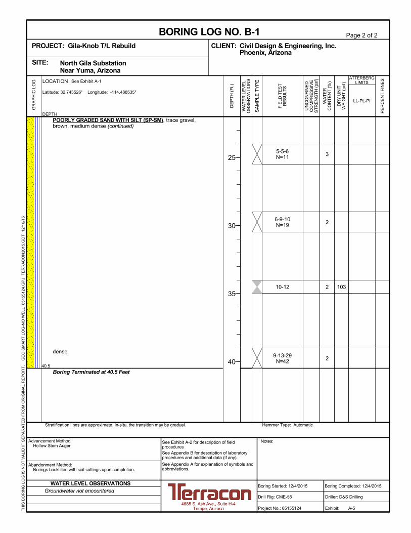
A total of four (4) test borings were drilled at the site on December 3 and 4, 2015. The boringswere drilled to a depth of approximately 40 feet below the existing ground surface at the boringlocations. The approximate locations of the borings are shown on the attached Site Plan andBoring Locations diagram, Exhibit A-1.
The borings were located in the field by using the site plan provided by Western showing theexisting structure locations. Latitude and longitude coordinates shown on the boring logs wereobtained from Google Earth Pro and should be considered approximate.
The test borings were advanced with a truck-mounted CME-55 drill rig utilizing 8-inch diameterhollow-stem augers. Continuous lithologic logs of each boring were recorded by the fieldgeologist during the drilling operations. At selected intervals, samples of the subsurfacematerials were taken by driving split-spoon (SPT) or ring-lined barrel samplers in generalaccordance with ASTM Standards. Bulk samples of subsurface materials were also obtainedfrom the auger cuttings.
Penetration resistance measurements were obtained by driving the split-spoon and ring-linedbarrel samplers into the subsurface materials with a 140-pound automatic hammer falling 30inches. The penetration resistance value is a useful index in estimating the consistency orrelative density of materials encountered.
Groundwater conditions were evaluated in each boring at the time of site exploration.

Water levels indicated on the soil boringlogs are the levels measured in theborehole at the times indicated.Groundwater level variations will occurover time. In low permeability soils,accurate determination of groundwaterlevels is not possible with short termwater level observations.
NoRecovery
ModifiedDames & MooreRing Sampler
GrabSample
ModifiedCalifornia
Ring Sampler
GENERAL NOTES
4 - 8
Unconfined CompressiveStrength, Qu, psf
ST
RE
NG
TH
TE
RM
S
Over 12 in. (300 mm)12 in. to 3 in. (300mm to 75mm)3 in. to #4 sieve (75mm to 4.75 mm)#4 to #200 sieve (4.75mm to 0.075mmPassing #200 sieve (0.075mm)
Particle Size
RELATIVE DENSITY OF COARSE-GRAINED SOILS
< 55 - 12> 12
Percent ofDry Weight
Descriptive Term(s)of other constituents
RELATIVE PROPORTIONS OF FINES
01 - 1011 - 30
> 30
Plasticity Index
SA
MP
LIN
G
LOCATION AND ELEVATION NOTES
> 99 4,000 to 8,000
2,000 to 4,000
MacroCore
1,000 to 2,000
500 to 1,000
less than 500
Stiff59 - 98
19 - 5810 - 29
Soft7 - 18
Very Soft0 - 60 - 3Very Loose
Hard
(More than 50% retained on No. 200 sieve.)Density determined by Standard Penetration Resistance
Includes gravels, sands and silts.
Percent ofDry Weight
Major Componentof Sample
Water Level After aSpecified Period of Time
Water InitiallyEncountered
Descriptive Term(s)of other constituents
< 1515 - 29> 30
Term
PLASTICITY DESCRIPTION
8 - 15
RockCore
Split SpoonShelby Tube
WA
TE
R L
EV
EL
30 - 50
5 - 9Medium-Stiff
3 - 42 - 44 - 9
< 30 - 1
Very Dense
Dense
Medium Dense
Ring SamplerBlows/Ft.
Ring SamplerBlows/Ft.
Standard Penetration orN-Value
Blows/Ft.
Very Stiff
Loose
Descriptive Term(Consistency)
Standard Penetration orN-Value
Blows/Ft.
TraceWithModifier
RELATIVE PROPORTIONS OF SAND AND GRAVEL GRAIN SIZE TERMINOLOGY
Water Level Aftera Specified Period of Time
TraceWithModifier
Bulk
Soil classification is based on the Unified Soil Classification System. Coarse Grained Soils have more than 50% of their dryweight retained on a #200 sieve; their principal descriptors are: boulders, cobbles, gravel or sand. Fine Grained Soils haveless than 50% of their dry weight retained on a #200 sieve; they are principally described as clays if they are plastic, andsilts if they are slightly plastic or non-plastic. Major constituents may be added as modifiers and minor constituents may beadded according to the relative proportions based on grain size. In addition to gradation, coarse-grained soils are definedon the basis of their in-place relative density and fine-grained soils on the basis of their consistency.
Unless otherwise noted, Latitude and Longitude are approximately determined using a hand-held GPS device. The accuracyof such devices is variable. Surface elevation data annotated with +/- indicates that no actual topographical survey wasconducted to confirm the surface elevation. Instead, the surface elevation was approximately determined from topographicmaps of the area.
> 8,000
DESCRIPTIVE SOIL CLASSIFICATION
(50% or more passing the No. 200 sieve.)Consistency determined by laboratory shear strength testing, field
visual-manual procedures or standard penetration resistance
(HP)
(T)
(b/f)
N
(PID)
(OVA)
Hand Penetrometer
Torvane
Standard PenetrationTest (blows per foot)
N value
Photo-Ionization Detector
Organic Vapor Analyzer
CONSISTENCY OF FINE-GRAINED SOILS
_
> 42> 30
19 - 4215 - 30> 50
10 - 18
BouldersCobblesGravelSandSilt or Clay
Non-plasticLowMediumHigh
Descriptive Term(Density)
DESCRIPTION OF SYMBOLS AND ABBREVIATIONS
FIE
LD
TE
ST
S

UNIFIED SOIL CLASSIFICATION SYSTEM
Criteria for Assigning Group Symbols and Group Names Using Laboratory Tests A Soil Classification
Group Symbol Group Name B
Coarse Grained Soils: More than 50% retained on No. 200 sieve
Gravels: More than 50% of coarse fraction retained on No. 4 sieve
Clean Gravels: Less than 5% fines C
Cu 4 and 1 Cc 3 E GW Well-graded gravel F Cu 4 and/or 1 Cc 3 E GP Poorly graded gravel F
Gravels with Fines: More than 12% fines C
Fines classify as ML or MH GM Silty gravel F,G,H Fines classify as CL or CH GC Clayey gravel F,G,H
Sands: 50% or more of coarse fraction passes No. 4 sieve
Clean Sands: Less than 5% fines D
Cu 6 and 1 Cc 3 E SW Well-graded sand I Cu 6 and/or 1 Cc 3 E SP Poorly graded sand I
Sands with Fines: More than 12% fines D
Fines classify as ML or MH SM Silty sand G,H,I Fines classify as CL or CH SC Clayey sand G,H,I
Fine-Grained Soils: 50% or more passes the No. 200 sieve
Silts and Clays: Liquid limit less than 50
Inorganic: PI 7 and plots on or above “A” line J CL Lean clay K,L,M PI 4 or plots below “A” line J ML Silt K,L,M
Organic: Liquid limit - oven dried
0.75 OL Organic clay K,L,M,N
Liquid limit - not dried Organic silt K,L,M,O
Silts and Clays: Liquid limit 50 or more
Inorganic: PI plots on or above “A” line CH Fat clay K,L,M PI plots below “A” line MH Elastic Silt K,L,M
Organic: Liquid limit - oven dried
0.75 OH Organic clay K,L,M,P
Liquid limit - not dried Organic silt K,L,M,Q Highly organic soils: Primarily organic matter, dark in color, and organic odor PT Peat
A Based on the material passing the 3-inch (75-mm) sieve B If field sample contained cobbles or boulders, or both, add “with cobbles
or boulders, or both” to group name. C Gravels with 5 to 12% fines require dual symbols: GW-GM well-graded
gravel with silt, GW-GC well-graded gravel with clay, GP-GM poorly graded gravel with silt, GP-GC poorly graded gravel with clay.
D Sands with 5 to 12% fines require dual symbols: SW-SM well-graded sand with silt, SW-SC well-graded sand with clay, SP-SM poorly graded sand with silt, SP-SC poorly graded sand with clay
E Cu = D60/D10 Cc = 6010
2
30
DxD
)(D
F If soil contains 15% sand, add “with sand” to group name. G If fines classify as CL-ML, use dual symbol GC-GM, or SC-SM.
H If fines are organic, add “with organic fines” to group name. I If soil contains 15% gravel, add “with gravel” to group name. J If Atterberg limits plot in shaded area, soil is a CL-ML, silty clay. K If soil contains 15 to 29% plus No. 200, add “with sand” or “with gravel,”
whichever is predominant. L If soil contains 30% plus No. 200 predominantly sand, add “sandy” to
group name. M If soil contains 30% plus No. 200, predominantly gravel, add
“gravelly” to group name. N PI 4 and plots on or above “A” line. O PI 4 or plots below “A” line. P PI plots on or above “A” line. Q PI plots below “A” line.

7
1
1
2
4
110
92
NP
17-20
6-17
12-13-12N=25
12-13-15N=28
12-16
7.0
POORLY GRADED SAND WITH GRAVEL (SP), trace silt, brown,medium dense
POORLY GRADED SAND WITH SILT (SP-SM), trace gravel,brown, medium dense
Hammer Type: AutomaticStratification lines are approximate. In-situ, the transition may be gradual.
GR
AP
HIC
LO
G
TH
IS B
OR
ING
LO
G IS
NO
T V
ALI
D IF
SE
PA
RA
TE
D F
RO
M O
RIG
INA
L R
EP
OR
T.
G
EO
SM
AR
T L
OG
-NO
WE
LL 6
515
512
4.G
PJ
TE
RR
AC
ON
2015
.GD
T
12/1
6/15
SITE:
Page 1 of 2
Advancement Method:Hollow Stem Auger
Abandonment Method:Borings backfilled with soil cuttings upon completion.
4685 S. Ash Ave., Suite H-4Tempe, Arizona
Notes:
Project No.: 65155124
Drill Rig: CME-55
Boring Started: 12/4/2015
BORING LOG NO. B-1Civil Design & Engineering, Inc.CLIENT:Phoenix, Arizona
Driller: D&S Drilling
Boring Completed: 12/4/2015
Exhibit: A-5
See Exhibit A-2 for description of fieldproceduresSee Appendix B for description of laboratoryprocedures and additional data (if any).
See Appendix A for explanation of symbols andabbreviations.
North Gila Substation Near Yuma, Arizona
PROJECT: Gila-Knob T/L Rebuild
UN
CO
NF
INE
DC
OM
PR
ES
SIV
ES
TR
EN
GT
H (
psf)
PE
RC
EN
T F
INE
S
WA
TE
RC
ON
TE
NT
(%
)
DR
Y U
NIT
WE
IGH
T (
pcf)
ATTERBERGLIMITS
LL-PL-PI
SA
MP
LE T
YP
E
WA
TE
R L
EV
EL
OB
SE
RV
AT
ION
S
DE
PT
H (
Ft.)
5
10
15
20
FIE
LD T
ES
TR
ES
ULT
S
DEPTH
LOCATION See Exhibit A-1
Latitude: 32.743526° Longitude: -114.488535°
Groundwater not encounteredWATER LEVEL OBSERVATIONS
3
2
2
2
103
5-5-6N=11
6-9-10N=19
10-12
9-13-29N=42
40.5
POORLY GRADED SAND WITH SILT (SP-SM), trace gravel,brown, medium dense (continued)
dense
Boring Terminated at 40.5 Feet
Hammer Type: AutomaticStratification lines are approximate. In-situ, the transition may be gradual.
GR
AP
HIC
LO
G
TH
IS B
OR
ING
LO
G IS
NO
T V
ALI
D IF
SE
PA
RA
TE
D F
RO
M O
RIG
INA
L R
EP
OR
T.
G
EO
SM
AR
T L
OG
-NO
WE
LL 6
515
512
4.G
PJ
TE
RR
AC
ON
2015
.GD
T
12/1
6/15
SITE:
Page 2 of 2
Advancement Method:Hollow Stem Auger
Abandonment Method:Borings backfilled with soil cuttings upon completion.
4685 S. Ash Ave., Suite H-4Tempe, Arizona
Notes:
Project No.: 65155124
Drill Rig: CME-55
Boring Started: 12/4/2015
BORING LOG NO. B-1Civil Design & Engineering, Inc.CLIENT:Phoenix, Arizona
Driller: D&S Drilling
Boring Completed: 12/4/2015
Exhibit: A-5
See Exhibit A-2 for description of fieldproceduresSee Appendix B for description of laboratoryprocedures and additional data (if any).
See Appendix A for explanation of symbols andabbreviations.
North Gila Substation Near Yuma, Arizona
PROJECT: Gila-Knob T/L Rebuild
UN
CO
NF
INE
DC
OM
PR
ES
SIV
ES
TR
EN
GT
H (
psf)
PE
RC
EN
T F
INE
S
WA
TE
RC
ON
TE
NT
(%
)
DR
Y U
NIT
WE
IGH
T (
pcf)
ATTERBERGLIMITS
LL-PL-PI
SA
MP
LE T
YP
E
WA
TE
R L
EV
EL
OB
SE
RV
AT
ION
S
DE
PT
H (
Ft.)
25
30
35
40
FIE
LD T
ES
TR
ES
ULT
S
DEPTH
LOCATION See Exhibit A-1
Latitude: 32.743526° Longitude: -114.488535°
Groundwater not encounteredWATER LEVEL OBSERVATIONS

583
2
1
3
4
98
106
24-17-76-14
21-50/5"
17-25-30N=55
12-23-28N=51
20-30/3"
4.0
20.0
SANDY SILTY CLAY (CL-ML), light brown, very stiff, weakcementation
SILTY SAND WITH GRAVEL (SM), light brown, very dense, weakto moderate cementation
POORLY GRADED SAND WITH GRAVEL (SP), trace silt, brown tolight brown, very dense, no to weak cementation
Hammer Type: AutomaticStratification lines are approximate. In-situ, the transition may be gradual.
GR
AP
HIC
LO
G
TH
IS B
OR
ING
LO
G IS
NO
T V
ALI
D IF
SE
PA
RA
TE
D F
RO
M O
RIG
INA
L R
EP
OR
T.
G
EO
SM
AR
T L
OG
-NO
WE
LL 6
515
512
4.G
PJ
TE
RR
AC
ON
2015
.GD
T
12/1
6/15
SITE:
Page 1 of 2
Advancement Method:Hollow Stem Auger
Abandonment Method:Backfilled with cement-bentonite grout upon completion.
4685 S. Ash Ave., Suite H-4Tempe, Arizona
Notes:
Project No.: 65155124
Drill Rig: CME-55
Boring Started: 12/3/2015
BORING LOG NO. B-2Civil Design & Engineering, Inc.CLIENT:Phoenix, Arizona
Driller: D&S Drilling
Boring Completed: 12/3/2015
Exhibit: A-6
See Exhibit A-2 for description of fieldproceduresSee Appendix B for description of laboratoryprocedures and additional data (if any).
See Appendix A for explanation of symbols andabbreviations.
North Gila Substation Near Yuma, Arizona
PROJECT: Gila-Knob T/L Rebuild
UN
CO
NF
INE
DC
OM
PR
ES
SIV
ES
TR
EN
GT
H (
psf)
PE
RC
EN
T F
INE
S
WA
TE
RC
ON
TE
NT
(%
)
DR
Y U
NIT
WE
IGH
T (
pcf)
ATTERBERGLIMITS
LL-PL-PI
SA
MP
LE T
YP
E
WA
TE
R L
EV
EL
OB
SE
RV
AT
ION
S
DE
PT
H (
Ft.)
5
10
15
20
FIE
LD T
ES
TR
ES
ULT
S
DEPTH
LOCATION See Exhibit A-1
Latitude: 32.746788° Longitude: -114.488083°
While drilling
WATER LEVEL OBSERVATIONS

2
13
15
50/4"
23-50/6"
19-44-50/3"
11-15-19N=34
40.5
POORLY GRADED SAND WITH GRAVEL (SP), trace silt, brown tolight brown, very dense, no to weak cementation (continued)
groundwater encountered at approximately 32 feet while drilling
dense
Boring Terminated at 40.5 Feet
Hammer Type: AutomaticStratification lines are approximate. In-situ, the transition may be gradual.
GR
AP
HIC
LO
G
TH
IS B
OR
ING
LO
G IS
NO
T V
ALI
D IF
SE
PA
RA
TE
D F
RO
M O
RIG
INA
L R
EP
OR
T.
G
EO
SM
AR
T L
OG
-NO
WE
LL 6
515
512
4.G
PJ
TE
RR
AC
ON
2015
.GD
T
12/1
6/15
SITE:
Page 2 of 2
Advancement Method:Hollow Stem Auger
Abandonment Method:Backfilled with cement-bentonite grout upon completion.
4685 S. Ash Ave., Suite H-4Tempe, Arizona
Notes:
Project No.: 65155124
Drill Rig: CME-55
Boring Started: 12/3/2015
BORING LOG NO. B-2Civil Design & Engineering, Inc.CLIENT:Phoenix, Arizona
Driller: D&S Drilling
Boring Completed: 12/3/2015
Exhibit: A-6
See Exhibit A-2 for description of fieldproceduresSee Appendix B for description of laboratoryprocedures and additional data (if any).
See Appendix A for explanation of symbols andabbreviations.
North Gila Substation Near Yuma, Arizona
PROJECT: Gila-Knob T/L Rebuild
UN
CO
NF
INE
DC
OM
PR
ES
SIV
ES
TR
EN
GT
H (
psf)
PE
RC
EN
T F
INE
S
WA
TE
RC
ON
TE
NT
(%
)
DR
Y U
NIT
WE
IGH
T (
pcf)
ATTERBERGLIMITS
LL-PL-PI
SA
MP
LE T
YP
E
WA
TE
R L
EV
EL
OB
SE
RV
AT
ION
S
DE
PT
H (
Ft.)
25
30
35
40
FIE
LD T
ES
TR
ES
ULT
S
DEPTH
LOCATION See Exhibit A-1
Latitude: 32.746788° Longitude: -114.488083°
While drilling
WATER LEVEL OBSERVATIONS
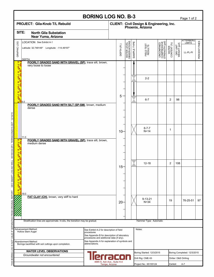
97
2
1
2
19
98
108
76-25-51
2-2
6-7
6-7-7N=14
12-18
9-13-21N=34
6.0
11.0
19.0
POORLY GRADED SAND WITH GRAVEL (SP), trace silt, brown,very loose to loose
POORLY GRADED SAND WITH SILT (SP-SM), brown, mediumdense
POORLY GRADED SAND WITH GRAVEL (SP), trace silt, brown,medium dense
FAT CLAY (CH), brown, very stiff to hard
Hammer Type: AutomaticStratification lines are approximate. In-situ, the transition may be gradual.
GR
AP
HIC
LO
G
TH
IS B
OR
ING
LO
G IS
NO
T V
ALI
D IF
SE
PA
RA
TE
D F
RO
M O
RIG
INA
L R
EP
OR
T.
G
EO
SM
AR
T L
OG
-NO
WE
LL 6
515
512
4.G
PJ
TE
RR
AC
ON
2015
.GD
T
12/1
6/15
SITE:
Page 1 of 2
Advancement Method:Hollow Stem Auger
Abandonment Method:Borings backfilled with soil cuttings upon completion.
4685 S. Ash Ave., Suite H-4Tempe, Arizona
Notes:
Project No.: 65155124
Drill Rig: CME-55
Boring Started: 12/3/2015
BORING LOG NO. B-3Civil Design & Engineering, Inc.CLIENT:Phoenix, Arizona
Driller: D&S Drilling
Boring Completed: 12/3/2015
Exhibit: A-7
See Exhibit A-2 for description of fieldproceduresSee Appendix B for description of laboratoryprocedures and additional data (if any).
See Appendix A for explanation of symbols andabbreviations.
North Gila Substation Near Yuma, Arizona
PROJECT: Gila-Knob T/L Rebuild
UN
CO
NF
INE
DC
OM
PR
ES
SIV
ES
TR
EN
GT
H (
psf)
PE
RC
EN
T F
INE
S
WA
TE
RC
ON
TE
NT
(%
)
DR
Y U
NIT
WE
IGH
T (
pcf)
ATTERBERGLIMITS
LL-PL-PI
SA
MP
LE T
YP
E
WA
TE
R L
EV
EL
OB
SE
RV
AT
ION
S
DE
PT
H (
Ft.)
5
10
15
20
FIE
LD T
ES
TR
ES
ULT
S
DEPTH
LOCATION See Exhibit A-1
Latitude: 32.749149° Longitude: -114.49197°
Groundwater not encounteredWATER LEVEL OBSERVATIONS

11297 21
23
20
2
98
101
14-21
14-19-23N=42
18-32/3"
20-35-37N=72
37.0
40.5
FAT CLAY (CH), brown, very stiff to hard (continued)
very dense
SILTY SAND WITH GRAVEL (SM), light brown, very dense,moderate cementation
Boring Terminated at 40.5 Feet
Hammer Type: AutomaticStratification lines are approximate. In-situ, the transition may be gradual.
GR
AP
HIC
LO
G
TH
IS B
OR
ING
LO
G IS
NO
T V
ALI
D IF
SE
PA
RA
TE
D F
RO
M O
RIG
INA
L R
EP
OR
T.
G
EO
SM
AR
T L
OG
-NO
WE
LL 6
515
512
4.G
PJ
TE
RR
AC
ON
2015
.GD
T
12/1
6/15
SITE:
Page 2 of 2
Advancement Method:Hollow Stem Auger
Abandonment Method:Borings backfilled with soil cuttings upon completion.
4685 S. Ash Ave., Suite H-4Tempe, Arizona
Notes:
Project No.: 65155124
Drill Rig: CME-55
Boring Started: 12/3/2015
BORING LOG NO. B-3Civil Design & Engineering, Inc.CLIENT:Phoenix, Arizona
Driller: D&S Drilling
Boring Completed: 12/3/2015
Exhibit: A-7
See Exhibit A-2 for description of fieldproceduresSee Appendix B for description of laboratoryprocedures and additional data (if any).
See Appendix A for explanation of symbols andabbreviations.
North Gila Substation Near Yuma, Arizona
PROJECT: Gila-Knob T/L Rebuild
UN
CO
NF
INE
DC
OM
PR
ES
SIV
ES
TR
EN
GT
H (
psf)
PE
RC
EN
T F
INE
S
WA
TE
RC
ON
TE
NT
(%
)
DR
Y U
NIT
WE
IGH
T (
pcf)
ATTERBERGLIMITS
LL-PL-PI
SA
MP
LE T
YP
E
WA
TE
R L
EV
EL
OB
SE
RV
AT
ION
S
DE
PT
H (
Ft.)
25
30
35
40
FIE
LD T
ES
TR
ES
ULT
S
DEPTH
LOCATION See Exhibit A-1
Latitude: 32.749149° Longitude: -114.49197°
Groundwater not encounteredWATER LEVEL OBSERVATIONS

51
5
1
NP
5-10
5-7-10N=17
15-22
15-36-34N=70
12-15-19N=34
5.0
11.0
POORLY GRADED SAND WITH SILT AND GRAVEL (SP-SM),loose
POORLY GRADED SAND WITH SILT (SP-SM), trace gravel,medium dense
SILTY SAND (SM), trace gravel, dense to very dense, weak tomoderate cementation
Hammer Type: AutomaticStratification lines are approximate. In-situ, the transition may be gradual.
GR
AP
HIC
LO
G
TH
IS B
OR
ING
LO
G IS
NO
T V
ALI
D IF
SE
PA
RA
TE
D F
RO
M O
RIG
INA
L R
EP
OR
T.
G
EO
SM
AR
T L
OG
-NO
WE
LL 6
515
512
4.G
PJ
TE
RR
AC
ON
2015
.GD
T
12/1
6/15
SITE:
Page 1 of 2
Advancement Method:Hollow Stem Auger
Abandonment Method:Borings backfilled with soil cuttings upon completion.
4685 S. Ash Ave., Suite H-4Tempe, Arizona
Notes:
Project No.: 65155124
Drill Rig: CME-55
Boring Started: 12/4/2015
BORING LOG NO. B-4Civil Design & Engineering, Inc.CLIENT:Phoenix, Arizona
Driller: D&S Drilling
Boring Completed: 12/4/2015
Exhibit: A-8
See Exhibit A-2 for description of fieldproceduresSee Appendix B for description of laboratoryprocedures and additional data (if any).
See Appendix A for explanation of symbols andabbreviations.
North Gila Substation Near Yuma, Arizona
PROJECT: Gila-Knob T/L Rebuild
UN
CO
NF
INE
DC
OM
PR
ES
SIV
ES
TR
EN
GT
H (
psf)
PE
RC
EN
T F
INE
S
WA
TE
RC
ON
TE
NT
(%
)
DR
Y U
NIT
WE
IGH
T (
pcf)
ATTERBERGLIMITS
LL-PL-PI
SA
MP
LE T
YP
E
WA
TE
R L
EV
EL
OB
SE
RV
AT
ION
S
DE
PT
H (
Ft.)
5
10
15
20
FIE
LD T
ES
TR
ES
ULT
S
DEPTH
LOCATION See Exhibit A-1
Latitude: 32.748832° Longitude: -114.495473°
Groundwater not encounteredWATER LEVEL OBSERVATIONS

2
20
20
20
94
92
16-30
10-13-17N=30
15-29
16-20-24N=44
28.0
40.5
SILTY SAND (SM), trace gravel, dense to very dense, weak tomoderate cementation (continued)
medium dense
FAT CLAY (CH), brown, hard
Boring Terminated at 40.5 Feet
Hammer Type: AutomaticStratification lines are approximate. In-situ, the transition may be gradual.
GR
AP
HIC
LO
G
TH
IS B
OR
ING
LO
G IS
NO
T V
ALI
D IF
SE
PA
RA
TE
D F
RO
M O
RIG
INA
L R
EP
OR
T.
G
EO
SM
AR
T L
OG
-NO
WE
LL 6
515
512
4.G
PJ
TE
RR
AC
ON
2015
.GD
T
12/1
6/15
SITE:
Page 2 of 2
Advancement Method:Hollow Stem Auger
Abandonment Method:Borings backfilled with soil cuttings upon completion.
4685 S. Ash Ave., Suite H-4Tempe, Arizona
Notes:
Project No.: 65155124
Drill Rig: CME-55
Boring Started: 12/4/2015
BORING LOG NO. B-4Civil Design & Engineering, Inc.CLIENT:Phoenix, Arizona
Driller: D&S Drilling
Boring Completed: 12/4/2015
Exhibit: A-8
See Exhibit A-2 for description of fieldproceduresSee Appendix B for description of laboratoryprocedures and additional data (if any).
See Appendix A for explanation of symbols andabbreviations.
North Gila Substation Near Yuma, Arizona
PROJECT: Gila-Knob T/L Rebuild
UN
CO
NF
INE
DC
OM
PR
ES
SIV
ES
TR
EN
GT
H (
psf)
PE
RC
EN
T F
INE
S
WA
TE
RC
ON
TE
NT
(%
)
DR
Y U
NIT
WE
IGH
T (
pcf)
ATTERBERGLIMITS
LL-PL-PI
SA
MP
LE T
YP
E
WA
TE
R L
EV
EL
OB
SE
RV
AT
ION
S
DE
PT
H (
Ft.)
25
30
35
40
FIE
LD T
ES
TR
ES
ULT
S
DEPTH
LOCATION See Exhibit A-1
Latitude: 32.748832° Longitude: -114.495473°
Groundwater not encounteredWATER LEVEL OBSERVATIONS

Geotechnical Engineering ReportGila-Knob T/L Rebuild, Phase 1 ■ Near Yuma, ArizonaMarch 2, 2016 ■ Terracon Project No. 65155124, Revision No. 1
Resourceful ■ Responsive ■ Reliable
APPENDIX BLABORATORY TEST RESULTS

Geotechnical Engineering ReportGila-Knob T/L Rebuild, Phase 1 ■ Near Yuma, ArizonaMarch 2, 2016 ■ Terracon Project No. 65155124, Revision No. 1
Laboratory Testing
Samples retrieved during the field exploration were taken to the laboratory for furtherobservation by the project geotechnical engineer and were classified in accordance with theUnified Soil Classification System (USCS) described in Appendix A. At that time, the fielddescriptions were confirmed or modified as necessary and an applicable laboratory testingprogram was formulated to determine engineering properties of the subsurface materials.
Laboratory tests were conducted on selected soil samples and the test results are presented inthis appendix. The laboratory test results were used for the geotechnical engineering analyses,and the development of foundation recommendations. Laboratory tests were performed ingeneral accordance with the applicable ASTM, local or other accepted standards.
Selected soil samples obtained from the site were tested for the following engineeringproperties:
n Atterberg Limits n Sieve Analysisn Moisture Content n Dry Densityn Direct Shear n Unconfined Compressionn pH n Soluble Sulfates

0
10
20
30
40
50
60
0 20 40 60 80 100
CH o
r
OH
CL o
r
OL
ML or OL
MH or OH
PL PIBoring ID Depth Description
POORLY GRADED SAND with SILT
SANDY SILTY CLAY
FAT CLAY
POORLY GRADED SAND with SILT
SP-SM
CL-ML
SP
SP-SM
Fines
PLASTICITY
INDEX
LIQUID LIMIT
"U" L
ine
"A" L
ine
NP
24
76
NP
NP
17
25
NP
NP
7
51
NP
7
58
97
5
LL USCS
B-1
B-2
B-3
B-4
ATTERBERG LIMITS RESULTSASTM D4318
14 - 15.5
0 - 4
19 - 20.5
5 - 6.5
4685 S. Ash Ave., Suite H-4Tempe, Arizona
PROJECT NUMBER: 65155124PROJECT: Gila-Knob T/L Rebuild
SITE: North Gila Substation Near Yuma, Arizona
CLIENT: Civil Design & Engineering, Inc. Phoenix, Arizona
EXHIBIT: B-2
LAB
OR
AT
OR
Y T
ES
TS
AR
E N
OT
VA
LID
IF S
EP
AR
AT
ED
FR
OM
OR
IGIN
AL
RE
PO
RT
.
AT
TE
RB
ER
G L
IMIT
S 6
5155
124.
GP
J T
ER
RA
CO
N20
15.G
DT
12
/16/
15
CL-ML

>>
0
5
10
15
20
25
30
35
40
45
50
55
60
65
70
75
80
85
90
95
100
0.0010.010.1110100
6.8
58.1
5.5
%Fines
LL PL PI
41 3/4 1/2 60
fine
B-1
B-2
B-3
B-4
2.44
3.10
GRAIN SIZE IN MILLIMETERS
PE
RC
EN
T F
INE
R B
Y W
EIG
HT
coarse fine
HYDROMETERU.S. SIEVE OPENING IN INCHES U.S. SIEVE NUMBERS
NP
17
25
NP
NP
7
51
NP
1.39
1.14
D100
Cc Cu
68.4
SILT OR CLAY
4
%Sand%GravelD30 D10
B-1
B-2
B-3
B-4
POORLY GRADED SAND with SILT (SP-SM)
SANDY SILTY CLAY (CL-ML)
FAT CLAY (CH)
POORLY GRADED SAND with SILT (SP-SM)
NP
24
76
NP
0.166
0.2
0.22
0.082
0.003
0.329
1.18
25
1.18
2.36
6 16 20 30 40 501.5 2006 810
0.0
7.9
0.0
0.0
0.09
0.106
14
14 - 15.5
0 - 4
19 - 20.5
5 - 6.5
3/8 3 100 1403 2
COBBLESGRAVEL SAND
USCS Classification
28.7
93.2
34.0
2.9
94.4
D60
coarse medium
Boring ID Depth
Boring ID Depth
GRAIN SIZE DISTRIBUTIONASTM D422
14 - 15.5
0 - 4
19 - 20.5
5 - 6.5
4685 S. Ash Ave., Suite H-4Tempe, Arizona
PROJECT NUMBER: 65155124PROJECT: Gila-Knob T/L Rebuild
SITE: North Gila Substation Near Yuma, Arizona
CLIENT: Civil Design & Engineering, Inc. Phoenix, Arizona
EXHIBIT: B-3
LAB
OR
AT
OR
Y T
ES
TS
AR
E N
OT
VA
LID
IF S
EP
AR
AT
ED
FR
OM
OR
IGIN
AL
RE
PO
RT
.
GR
AIN
SIZ
E: U
SC
S-2
651
551
24.G
PJ
TE
RR
AC
ON
2012
.GD
T 1
2/1
6/1
5

DIRECT SHEAR TEST OF SOILS UNDER CONSOLIDATED DRAINED CONDITIONSASTM D3080
FRICTION ANGLE COHESION NORMAL NORMAL NORMALAT MAXIMUM SHEAR STRESS 31.0 deg 312 psf STRESS, psf STRESS, psf STRESS, psfAT MAXIMUM DISPLACEMENT 30.9 deg 0 psf 1000 2000 4000 INITIAL AREA, in2 INITIAL MOISTURE, % 5.0 5.0 5.0 INITIAL LENGTH, in INITIAL DRY DENSITY, pcf 86.3 88.3 87.0 SPECIFIC GRAVITY INITIAL SATURATION, % 14 15 15 SG ASSUMED INITIAL VOID RATIO 0.92 0.87 0.90 SG TESTED FINAL MOISTURE, % 33.2 30.8 30.8 LIQUID LIMIT FINAL SATURATION, % 100 100 100 PLASTIC LIMIT FINAL VOID RATIO 0.88 0.82 0.82 PLASTICITY INDEX MAXIMUM SHEAR STRESS, psf 886 1556 2705
DISPLACEMENT AT MAXIMUM SHEAR, in 0.093 0.095 0.153 SHEAR STRESS AT MAX DISPLACEMENT, psf 598 1197 2394 MAXIMUM DISPLAEMENT, in 0.451 0.451 0.451
SAMPLE TYPE RATE OF LOADING, in/min 0.0160 0.0160 0.0160 DESCRIPTION Poorly Graded Sand w/ Silt (SP-SM)
PROJECT NAME: Gila-Knob T/L Rebuild BORING NO.
LOCATION: Near Yuma DEPTH, feet
JOB NO.: SHEAR:
DATE:C:\Users\jrhuston\Desktop\65155124 Gila-Knob\[65155124 B-1 @ 19 4000 Direct Shear.xls]Sample Data
INUNDATED
19.0' TO 20.0'
B-1
1.0004.596
12/15/2015
65155124
X2.65
UNDISTURBED
0
1000
2000
3000
4000
5000
0 1000 2000 3000 4000 5000 6000 7000 8000
SHEA
RST
RES
S,ps
f
NORMAL STRESS, psf
SHEAR STRENGTH
MAXIMUM SHEAR STRESS AT MAXIMUM DISPLACEMENT
EXHIBIT: B-4

BORING NO.DEPTH, feet
SHEAR:
C:\Users\jrhuston\Desktop\65155124 Gila-Knob\[65155124 B-1 @ 19 4000 Direct Shear.xls]Sample Data
B-119.0' TO 20.0'INUNDATED
Gila-Knob T/L RebuildNear Yuma65155124
12/15/2015
0
500
1000
1500
2000
2500
3000
0.000 0.050 0.100 0.150 0.200 0.250 0.300 0.350 0.400 0.450 0.500
SHEA
RST
RES
S,ps
f
HORIZONTAL DISPLACEMENT, inch
SHEAR STRESS Result 1
Result 2
Result 3
-0.015
-0.010
-0.005
0.000
0.005
0.010
0.015
0.020
0.000 0.050 0.100 0.150 0.200 0.250 0.300 0.350 0.400 0.450 0.500
VER
TIC
ALD
ISPL
ACEM
ENT,
in
HORIZONTAL DISPLACEMENT, in
DISPLACEMENT Result 1
Result 2
Result 3Dilation
Contraction
EXHIBIT: B-5

DIRECT SHEAR TEST OF SOILS UNDER CONSOLIDATED DRAINED CONDITIONSASTM D3080
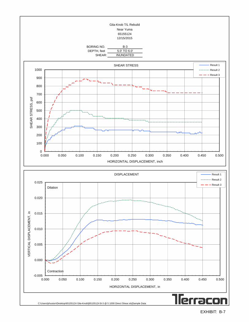
FRICTION ANGLE COHESION NORMAL NORMAL NORMALAT MAXIMUM SHEAR STRESS 37.5 deg 120 psf STRESS, psf STRESS, psf STRESS, psfAT MAXIMUM DISPLACEMENT 33.6 deg 48 psf 250 500 1000 INITIAL AREA, in2 INITIAL MOISTURE, % 2.2 2.2 2.7 INITIAL LENGTH, in INITIAL DRY DENSITY, pcf 98.0 98.5 96.0 SPECIFIC GRAVITY INITIAL SATURATION, % 8 9 10 SG ASSUMED INITIAL VOID RATIO 0.69 0.68 0.72 SG TESTED FINAL MOISTURE, % 2.2 2.2 2.6 LIQUID LIMIT FINAL SATURATION, % 9 9 10 PLASTIC LIMIT FINAL VOID RATIO 0.68 0.66 0.69 PLASTICITY INDEX MAXIMUM SHEAR STRESS, psf 311 503 886
DISPLACEMENT AT MAXIMUM SHEAR, in 0.085 0.073 0.111 SHEAR STRESS AT MAX DISPLACEMENT, psf 227 359 718 MAXIMUM DISPLAEMENT, in 0.451 0.451 0.451
SAMPLE TYPE RATE OF LOADING, in/min 0.0160 0.0160 0.0160 DESCRIPTION Poorly Graded Sand (SP)
PROJECT NAME: Gila-Knob T/L Rebuild BORING NO.
LOCATION: Near Yuma DEPTH, feet
JOB NO.: SHEAR:
DATE:C:\Users\jrhuston\Desktop\65155124 Gila-Knob\[65155124 B-3 @ 5 1000 Direct Shear.xls]Sample Data
12/15/2015
65155124
X2.65
UNDISTURBED
1.0004.596
INUNDATED
5.0' TO 6.0'
B-3
0
200
400
600
800
1000
1200
0 200 400 600 800 1000 1200 1400 1600 1800 2000
SHEA
RST
RES
S,ps
f
NORMAL STRESS, psf
SHEAR STRENGTH
MAXIMUM SHEAR STRESS AT MAXIMUM DISPLACEMENT
EXHIBIT: B-6
BORING NO.DEPTH, feet
SHEAR:
C:\Users\jrhuston\Desktop\65155124 Gila-Knob\[65155124 B-3 @ 5 1000 Direct Shear.xls]Sample Data
Gila-Knob T/L RebuildNear Yuma65155124
12/15/2015
B-35.0' TO 6.0'
INUNDATED
0
100
200
300
400
500
600
700
800
900
1000
0.000 0.050 0.100 0.150 0.200 0.250 0.300 0.350 0.400 0.450 0.500
SHEA
RST
RES
S,ps
f
HORIZONTAL DISPLACEMENT, inch
SHEAR STRESS Result 1
Result 2
Result 3
-0.005
0.000
0.005
0.010
0.015
0.020
0.025
0.000 0.050 0.100 0.150 0.200 0.250 0.300 0.350 0.400 0.450 0.500
VER
TIC
ALD
ISPL
ACEM
ENT,
in
HORIZONTAL DISPLACEMENT, in
DISPLACEMENT Result 1
Result 2
Result 3Dilation
Contraction
EXHIBIT: B-7

0
1,000
2,000
3,000
4,000
5,000
6,000
7,000
8,000
9,000
10,000
11,000
12,000
0 1.0 2.0 3.0 4.0 5.0
LL PL PI
81.51
0.68
2.41
5.06
Percent < #200 Sieve
AXIAL STRAIN - %
Remarks:
SPECIMEN FAILURE PHOTOGRAPH
SAMPLE DESCRIPTION: FAT CLAY (CH)
Unconfined Compressive Strength (psf)
Undrained Shear Strength: (psf)
UNCONFINED COMPRESSION TESTASTM D2166
5648
SAMPLE TYPE: RING
Assumed Specific Gravity:
Calculated Void Ratio:
Height / Diameter Ratio:
SPECIMEN TEST DATA
2.65
2.10
4.54
Moisture Content: %
Dry Density: pcf
Diameter: in.
Height: in.
Calculated Saturation: %
Failure Strain: %
Strain Rate: in/min
CO
MP
RE
SS
IVE
ST
RE
SS
- p
sf
21
99
11297
0.0200
SAMPLE LOCATION: B-3 @ 24 - 25 feet
4685 S. Ash Ave., Suite H-4Tempe, Arizona
PROJECT NUMBER: 65155124PROJECT: Gila-Knob T/L Rebuild
SITE: North Gila Substation Near Yuma, Arizona
CLIENT: Civil Design & Engineering, Inc. Phoenix, Arizona
EXHIBIT: B-8
LAB
OR
AT
OR
Y T
ES
TS
AR
E N
OT
VA
LID
IF S
EP
AR
AT
ED
FR
OM
OR
IGIN
AL
RE
PO
RT
.
UN
CO
NF
INE
D W
ITH
PH
OT
OS
651
5512
4.G
PJ
TE
RR
AC
ON
2012
.GD
T
12/1
6/15

B-1 5.0 - 6.0 SP 110 1 1, 2B-1 9.0 - 10.5 SP-SM 1 2
B-1 14.0 - 15.5 SP-SM 2 7 NP NP NP
B-1 19.0 - 20.0 SP-SM 92 4 1, 2B-1 24.0 - 25.5 SP-SM 3 2
B-1 29.0 - 30.5 SP-SM 2 2B-1 34.0 - 35.0 SP-SM 103 2 1, 2
B-1 39.0 - 40.5 SP-SM 2 2
B-2 0.0 - 4.0 CL-ML 58 24 17 7 8.3 5928B-2 2.0 - 3.0 CL-ML 98 3 1, 2
B-2 5.0 - 5.9 SM 2 2B-2 9.0 - 10.5 SM 1 2
B-2 14.0 - 15.5 SM 3 2
B-2 19.0 - 19.8 SM 106 4 1, 2B-2 29.0 - 29.5 SP 2 2
B-2 34.0 - 35.3 SP 13 2B-2 39.0 - 40.5 SP 15 2
B-3 5.0 - 6.0 SP 98 2 1, 2
B-3 9.0 - 10.5 SP-SM 1 2B-3 14.0 - 15.0 SP 108 2 1, 2
B-3 19.0 - 20.5 SP 19 97 76 25 51B-3 24.0 - 25.0 CH 98 21 1, 2
B-3 29.0 - 30.5 CH 23 8.0 602 2
B-3 34.0 - 34.8 CH 101 20 1, 2B-3 39.0 - 40.5 SM 2 2
50pH Resistivity
(ohm-cm)Sulfates(ppm)
Chlorides(ppm)
DryDensity
(pcf)
Expansion(%)
Corrosivity
Dry Density(pcf)
Atterberg Limits
In-Situ Properties
Passing#200
Sieve (%)
Classification
PL PI
WaterContent
(%)
Remarks
Expansion Testing
Surcharge(psf)
WaterContent (%) LL
USCSSoil
Class.Expansion
IndexEI
REMARKS1. Dry Density and/or moisture determined from one or more rings of a multi-ring sample.2. Visual Classification.3. Submerged to approximate saturation.4. Expansion Index in accordance with ASTM D4829-95.5. Air-Dried Sample
BoreholeNo.
Depth(ft.)
SUMMARY OF LABORATORY RESULTS
PROJECT: Gila-Knob T/L Rebuild PROJECT NUMBER: 65155124
CLIENT: Civil Design & Engineering, Inc. Phoenix, Arizona
SITE: North Gila Substation Near Yuma, Arizona
PH. 480-897-8200 FAX. 480-897-1133
4685 S. Ash Ave., Suite H-4Tempe, Arizona
EXHIBIT: B-9
TH
IS B
OR
ING
LO
G IS
NO
T V
ALI
D IF
SE
PA
RA
TE
D F
RO
M O
RIG
INA
L R
EP
OR
T.
S
OIL
PR
OP
ER
TIE
S 2
651
5512
4.G
PJ
TE
RR
AC
ON
2012
.GD
T 1
2/16
/15

B-4 5.0 - 6.5 SP-SM 1 5 NP NP NPB-4 14.0 - 15.5 SM 5 2
B-4 19.0 - 20.5 SM 1 2
B-4 24.0 - 25.0 SM 94 2 1, 2B-4 29.0 - 30.5 CH 20 2
B-4 34.0 - 35.0 CH 92 20 1, 2B-4 39.0 - 40.5 CH 20 2
50pH Resistivity
(ohm-cm)Sulfates(ppm)
Chlorides(ppm)
DryDensity
(pcf)
Expansion(%)
Corrosivity
Dry Density(pcf)
Atterberg Limits
In-Situ Properties
Passing#200
Sieve (%)
Classification
PL PI
WaterContent
(%)
Remarks
Expansion Testing
Surcharge(psf)
WaterContent (%) LL
USCSSoil
Class.Expansion
IndexEI
REMARKS1. Dry Density and/or moisture determined from one or more rings of a multi-ring sample.2. Visual Classification.3. Submerged to approximate saturation.4. Expansion Index in accordance with ASTM D4829-95.5. Air-Dried Sample
BoreholeNo.
Depth(ft.)
SUMMARY OF LABORATORY RESULTS
PROJECT: Gila-Knob T/L Rebuild PROJECT NUMBER: 65155124
CLIENT: Civil Design & Engineering, Inc. Phoenix, Arizona
SITE: North Gila Substation Near Yuma, Arizona
PH. 480-897-8200 FAX. 480-897-1133
4685 S. Ash Ave., Suite H-4Tempe, Arizona
EXHIBIT: B-10
TH
IS B
OR
ING
LO
G IS
NO
T V
ALI
D IF
SE
PA
RA
TE
D F
RO
M O
RIG
INA
L R
EP
OR
T.
S
OIL
PR
OP
ER
TIE
S 2
651
5512
4.G
PJ
TE
RR
AC
ON
2012
.GD
T 1
2/16
/15