Embed Size (px)
Citation preview

Geotechnical Engineering Report
Unalaska Library Improvements
Prepared For:
ECI, Inc. 3909 Arctic Blvd, Suite 103
Anchorage, AK 99503
Prepared By:
1506 West 36th Avenue
Anchorage, Alaska 99503
PND No. 181140 July 2019

July 2019 Unalaska Library Improvements Geotechnical Report
i
Table of Contents Table of Figures ............................................................................................................................................. ii
List of Tables ................................................................................................................................................ iii
1. INTRODUCTION ..................................................................................................................................... 1
2. BACKGROUND ....................................................................................................................................... 1
2.1 Exploration .................................................................................................................................... 1
Field Exploration Equipment and Methods .......................................................................................... 2
2.2 Geology, Geomorphology and Climate ......................................................................................... 3
Surface Conditions ................................................................................................................................ 3
Climate .................................................................................................................................................. 3
Regional Geology .................................................................................................................................. 4
Seismic Considerations ......................................................................................................................... 4
3. SUBSURFACE and SITE CHARACTERIZATION ......................................................................................... 6
3.1 As‐Built Borehole Locations .......................................................................................................... 6
3.2 Laboratory Characterization ......................................................................................................... 6
3.3 Soil Properties in Summary ........................................................................................................... 7
Soil Lithology ......................................................................................................................................... 7
Expansive and Collapsible Soils and Rock ............................................................................................. 7
Groundwater ......................................................................................................................................... 7
Contaminants (VOCs) ............................................................................................................................ 8
4. Engineering Discussion and Recommendations ................................................................................... 8
4.1 Stability Evaluation........................................................................................................................ 8
Slope Stability and Lateral Spreading ................................................................................................... 8
Loss of Bearing Capacity ....................................................................................................................... 8
Liquefaction .......................................................................................................................................... 8

July 2019 Unalaska Library Improvements Geotechnical Report
ii
4.2 Foundation Considerations ........................................................................................................... 8
Bearing Capacity and Settlement .......................................................................................................... 8
Lateral Load Resistance ....................................................................................................................... 10
Uplift Resistance ................................................................................................................................. 10
4.3 Utilities Recommendations ......................................................................................................... 10
4.4 Pavement Recommendations ..................................................................................................... 10
4.5 Construction Recommendations ................................................................................................ 10
Site Preparation .................................................................................................................................. 11
Excavations ......................................................................................................................................... 11
Drainage and Control of Water ........................................................................................................... 11
Fill and Compaction – General Recommendations ............................................................................. 11
5. LIMITATIONS and CLOSURE ................................................................................................................ 12
6. REFERENCES ........................................................................................................................................ 13
APPENDIX A — BOREHOLE LOGS ...................................................................................................................... 1
APPENDIX B — Summary of Lab and Field Characteristics ........................................................................... 1
Table of Figures
Figure 2‐1. Project Vicinity Map .................................................................................................................... 2
Figure 2‐2. Site Surface Overview Photo……..…………………………………………………………………………………………..3
Figure 3‐1. As‐Built Borehole Locations ........................................................................................................ 6
Figure 4‐1. Allowable Bearing Capacity for Continuous Footings (based on AASHTO 10.6.3) ..................... 9

July 2019 Unalaska Library Improvements Geotechnical Report
iii
List of Tables
Table 2‐1. Climate Summary ......................................................................................................................... 4
Table 2‐2. Seismic Design Parameters per ASCE 7‐10 .................................................................................. 4
Table 3‐1. Lab Test Summary ........................................................................................................................ 7
Table 3‐2. Idealized Soil Properties ............................................................................................................... 7

1
UNALASKA LIBRARY IMPROVEMENTS Geotechnical Report
1. INTRODUCTION
This report presents the geotechnical data collected and the analysis performed by PND Engineers, Inc. (PND) in support of the Unalaska Library Addition and Remodel project. This project will expand the existing Unalaska Public Library with a new building addition, construct a new plaza area, and conduct interior renovations of the existing facility. The objective of the geotechnical investigation was to determine the subsurface soil properties of the library exterior where construction of the new building addition is proposed, for potential building additions in the future, and to determine if any soil contamination is present at the site.
PND performed the work in accordance with the proposal City of Unalaska – Department of Public Works Library Expansion Test Holes, dated January 9, 2019.
The Geotechnical Report begins with a project background which includes an exploration narrative, description of the site geology, geomorphology, climate and permafrost soil features. Section 3 presents the as‐built borehole locations, discusses laboratory testing, and summarizes the soil properties developed from the lab testing program and field logs. All data is presented in the report appendices.
The Data Report contains two appendices:
Appendix A –Test Pit Logs presents the complete borehole log set from the exploratory borings of this investigation.
Appendix B – Summary of Lab and Field Characteristics presents the complete summary of results from the lab testing program and field characteristics for all the samples.
2. BACKGROUND
The project background includes an exploration narrative, description of the site geology, geomorphology, climate, and seismic considerations.
The existing Unalaska Public Library building was constructed in 1998. The building structure is located between Eleanor Drive to the north and a steep rock‐faced cliff rising above the Library to the south. The west side of the building includes the Library main entrance, a landscaped drainage swale, and an asphalt pavement parking lot. The east side of the Library building consists of a gravel surfaced area which is utilized as an auxiliary parking lot area.
Proposed Unalaska Public Library building and site improvements include construction of a new building addition at the west (front) side of the existing building, new concrete plaza and walkways, storm drain utility modifications, and new landscaping features.
2.1 Exploration PND performed a geotechnical investigation on May 21, 2019 to investigate subsurface conditions to support design of the proposed project. 11 test pits were performed.

July 2019 Unalaska Library Improvements Geotechnical Report
2
Figure 2‐1. Project Vicinity Map
FIELD EXPLORATION EQUIPMENT AND METHODS The geotechnical exploration was performed by Northern Alaska Contractors, LLC using excavators to dig test pits. Test pits located on the building’s rear side were excavated using a Link‐Belt 145 excavator with a one (1) cubic yard bucket attachment. Test pits located at the front on the building were excavated using a smaller rubber‐track CAT 305C excavator with a one‐half (1/2) cubic yard buck attachment. The smaller rubber‐track excavator was used for these test pits to mitigate potential damage to the existing asphalt, concrete, and landscape features. A rubber‐tire Volvo L220E loader and ten (10) cubic yard capacity end dump truck were also used to support excavation activities and haul excess material off‐site.
The existing asphalt or concrete surfaces were not damaged due to contractor equipment or activities during the field investigation. Contractor made special effort to preserve the vegetative mating and top soil during excavation activities, where present. Contractor laid the salvaged vegetative mat over the disturbed area and lightly compacted the area using the underside of the excavator bucket once the test pit was backfilled to the appropriate elevation.
The field sampling consisted of grab samples from either the test pit floor, side, or the excavator bucket at selected intervals in the test pits. Samples collected during the field investigation are intended to represent homogenous soil layers below the ground surface.
Contaminated soils sampling was also performed as part of the field geotechnical investigation using a photoionization device (PID). The PID was professionally calibrated by a certified technician (TTT Environmental) in Anchorage, Alaska on May 20, 2019. Summaries of soils properties and contaminated soils testing results are discussed in Section 3.3 of this report.

July 2019 Unalaska Library Improvements Geotechnical Report
3
2.2 Geology, Geomorphology and Climate
SURFACE CONDITIONS The front (west) side of the Library building consists on an asphalt pavement surface parking lot, concrete landing area, and landscaping features including drainage swales. The front side of the building is generally sloped from west‐to‐east with average slopes of 1 to 4 percent. The north side of the Library building consists of a seeded area which is sloped to drain away from the building towards Eleanor Drive. The rear (east) side of the Library building consists of a gravel surfaced parking lot and is generally sloped towards the east towards a drainage swale at the east end of the parking lot. The south side of the building consists of varying seeded and tundra vegetation. The south side of the Library building is also located immediately adjacent to a steep rock‐faced cliff formation which rises approximately 40 to 50 feet above the building floor elevation. A site surface overview photo, looking southeast, is included for reference in Figure 2‐2 below.
Figure 2‐2. Site Surface Overview Photo
CLIMATE Unalaska sits within a maritime climate zone with temperatures influenced by open water in the summer and offshore sea ice in the winter. The average daily temperatures recorded in Unalaska range from 36 to 57°F, with a mean annual temperature of 40°F. Extreme temperatures have been recorded from ‐5 to 79°F (Alaska Climate Summary).

July 2019 Unalaska Library Improvements Geotechnical Report
4
Annual precipitation averages about 57 inches water equivalent, which includes approximately 91 inches of snow (Alaska Climate Summary). The average recorded wind speed at the Unalaska NOAA meteorological station is about 11 mph.
Table 2‐1. Climate Summary
Average Air Temperature 40.1 °F
Average Thawing Index 3,100 °F‐Days
Design Thawing Index 5,100 °F‐Days
Average Freezing Index 200 °F‐Days
Design Freezing Index 600 °F‐Days
REGIONAL GEOLOGY The Aleutian Trench is located south of Unalaska Island. Subduction along the Aleutian Trench is the major tectonic force affecting the geology of the region. The subduction zone forms a linear belt of volcanoes parallel to the trench that makes up the Ring of Fire. Volcanoes are common in the Unalaska area. The eastern Aleutian volcanoes overlie continental and marine sedimentary rocks that range in age from mid‐Paleozoic to Holocene, volcanic rocks of late Mesozoic and mid—Tertiary age (less than 65 million years old), and plutonic rocks of the Laska‐Aleutian range batholith that range from the Jurassic to early Tertiary age. Glacial erosion is prominent throughout the island in the form of U‐shaped valleys, cirques, and various ice‐scoured features.
SEISMIC CONSIDERATIONS The Unalaska area is part of the Aleutian Islands and is located in one of the most seismically active zones in the world. Large magnitude earthquakes are common to the area and could result in damage to manmade structures. Any non‐engineered loose fills may fail in a large seismic event. The failures may consist of settlement and/or slope failures due to liquefaction. Unalaska Island sits approximately 108 miles north of the Aleutian Megathrust Subduction Zone Interface which is the primary source of all seismicity at or near the project site. The convergence and slip along the Megathrust is estimated to be about 2.2 to 2.9 inches per year in a north‐northwest direction (Alaska Earthquake Information Center, AEIC). The Megathrust was the locus of the 1964 moment magnitude, Mw, 9.2 Alaska earthquake, which ruptured approximately 500 miles along the strike of the subduction zone interface (Shennan et al., 2009). Several earthquakes of magnitude over 8.0 have been recorded along the Aleutian chain including many larger than Mw of 6.0 (AEIC).
Seismic design parameters, based upon maps provided by USGS (www.usgs.gov/) and ASCE 7‐10 are provided in Table 3 1. Seismic design for all structures shall comply with the appropriate design code.
Table 2‐2. Seismic Design Parameters per ASCE 7‐10
Return Period 2475 years (2% in 50 years)
Risk Category II
Site Class D
Peak Ground Acceleration 0.5
Ss (0.2 sec period acceleration) 1.5
S1 (1.0 sec period acceleration) 0.6
Moment Magnitude, Mw 7.4

July 2019 Unalaska Library Improvements Geotechnical Report
5
The site class was determined based on the procedure as outlined in ASCE 7‐10 Minimum Design Loads for Buildings and Other Structures.

July 2019 Unalaska Library Improvements Geotechnical Report
6
3. SUBSURFACE and SITE CHARACTERIZATION
The following section summarizes the soil characteristics of the geotechnical exploration conducted at the project site. The characterizations and index variables are based on lab testing and field logging from this exploration. The following sections present test hole locations and discuss the laboratory testing program and results. The final section presents a summary of material and soil properties.
3.1 As‐Built Borehole Locations A total of 11 test pits were excavated during the geotechnical investigation. As‐built borehole locations are shown on the map below.
Figure 3‐1. As‐Built Borehole Locations
3.2 Laboratory Characterization The samples were transported to PND’s geotechnical laboratory in Anchorage for testing. All tests were performed to ASTM standards where applicable. A total of nine (9) lab tests were performed. The lab test summary is shown in Table 3‐1.
Lab characterizations included the following listed tests.
Moisture Content/Classification (ASTM D4318)
Description and Identification of Soils—Visual‐Manual Procedure (ASTM D2487, D2488)

July 2019 Unalaska Library Improvements Geotechnical Report
7
Particle Size Analysis (ASTM D422)
Table 3‐1. Lab Test Summary
Test Type Quantity
Moisture Content with Classification (ASTM D2487 / D2488 / D2216) 5
Gradation of Soils (ASTM D6913) 4
Total Lab Tests 9
Full sieve stack gradations were performed on select coarse grained materials. Visual‐Manual classifications and moisture contents were performed on select fine‐grained materials.
The results of the laboratory testing program are shown in Appendix B – Summary of Lab and Field Characterizations. Lab results are also shown in the borehole logs at corresponding columns with given soil lithologies.
3.3 Soil Properties in Summary
SOIL LITHOLOGY The soil conditions generally consisted of an organic mat consisting of grass, tundra, and/or roots overlying 1 foot of sand with gravel. This was underlain by gravel with sand. Trace shells and cobbles were identified in the boreholes. Discontinuous layers of Silty Gravel and Silty Sand were identified in two test pits between 2.5 feet and 4 feet below ground surface (bgs).
The idealized soil layers and properties encountered are provided in Table 3‐2.
Table 3‐2. Idealized Soil Properties
Layer Depth (ft) Total Unit
Weight (pcf) φ’peak (deg)
c' (psf)
Organics 0 – 0.5 40 ‐ ‐
Sand with Gravel 0.5 – 1.5 125 32 ‐
Gravel with Sand 1.5 – 6 135 35 ‐
Gradation curves are located in Appendix B.
EXPANSIVE AND COLLAPSIBLE SOILS AND ROCK Rock was encountered in several test holes during PND’s exploration. The depth of the rock varied from 1.5 feet bgs to 7.5 feet bgs. It was not clear during exploration if the rock was bedrock or boulders resulting in refusal. There was no indication of collapsible of liquefiable soils. The soils encountered are generally non‐frost susceptible (NFS) to Slightly Frost Susceptible (USACE frost susceptibility classification F‐1) based on the composition and fines contents.
GROUNDWATER No groundwater was encountered during PND’s exploration.

July 2019 Unalaska Library Improvements Geotechnical Report
8
CONTAMINANTS (VOCS) Sampling of insitu soils for volatile organic compounds (VOCs) was performed as part of the on‐site geotechnical investigation activities. A PID was used to test the soils for evidence of VOCs at intervals of approximately two (2) feet in depth. The VOC readings are recorded on the borelogs. Evidence of VOCs was not encountered in the soils sampled during the exploration.
4. Engineering Discussion and Recommendations
4.1 Stability Evaluation No stability concerns were identified for the proposed scope of work.
SLOPE STABILITY AND LATERAL SPREADING Permanent slopes greater than 24‐inches are not anticipated as part of this project. All slopes should be constructed at a 2 to 1 (horizontal to vertical) slope. A side slope of 2:1 (horizontal to vertical) is recommended for temporary slopes, and 3:1 (horizontal to vertical) for permanent slopes in the in‐situ soils, and 2:1 (horizontal to vertical) for permanent slopes with engineered materials.
LOSS OF BEARING CAPACITY Assuming the footings are not bearing on deleterious material, an inspection of the soil type suggest that the risk of loss of bearing capacity of the top 8 feet of soil (the bottom of the test pits) during a seismic event is low.
LIQUEFACTION Earthquake‐induced liquefaction generally occurs only under particular conditions, including a high groundwater table, strong earthquake ground shaking of long duration, and loose uniform sands. The soils encountered are not expected to be liquefiable and a liquefaction analysis was not performed as part of this report.
4.2 Foundation Considerations Shallow and deep foundations are used to transfer building loads to the underlying soils. The soil type, consistency, density, heave/swell/collapse potential, ground water table, and depth to and type of bedrock are all considered in the type of foundation recommended for the proposed infrastructure. PND recommends the use of shallow foundations to carry the expected loads.
BEARING CAPACITY AND SETTLEMENT Design of a shallow foundation must consider the bearing capacity of the underlying soils, as well as the potential for settlement and the effects of seasonal frost action. In general, foundation designs should be consistent with the current edition of the IBC with any local amendments or requirements for footing depths.
Perimeter strip footings and interior spread footings should bear on a minimum of 4 inches of classified, compacted structural fill prepared in accordance with our recommendations. If footing preparations follow our recommendations, they may be designed according to the following criteria:
Maximum Allowable Bearing Pressure
o Static Loads (Dead and Normal Live): See Figure 4‐1
o Transient Loads (Wind and Seismic): Increase static by 33%

July 2019 Unalaska Library Improvements Geotechnical Report
9
The effective bearing area of eccentrically loaded footings will be less than the actual footing dimensions, and may vary depending on anticipated design loads and eccentricity.
The allowable bearing capacity for the proposed spread footings should be assumed to be 4,000 psf.
The allowable bearing capacity for the strip footings can be determined from Figure 4‐1 for different footing widths. The solid line represents the bearing capacity where 1 inch of settlement occurs under the footing.
Figure 4‐1. Allowable Bearing Capacity for Continuous Footings (based on AASHTO 10.6.3)
Depth of Embedment
o Perimeter Strip Footing: 24 inches, min. o Isolated, Interior Spread Footing: 18 inches, min.
Perimeter footings are assumed to be warm footings. Depth is measured from the adjacent grade to the bottom of the footing.
Settlement (non‐liquefaction)
o Total Settlement: 1 inch o Differential Settlement: 0.75 inch
Settlement from normally occurring static, live, and transient loads.
Settlement (liquefaction)
A liquefaction analysis was not performed as part of this geotechnical investigation.

July 2019 Unalaska Library Improvements Geotechnical Report
10
These recommended bearing capacities assume that the footings bear on structural fill material and not any organic or peat material.
LATERAL LOAD RESISTANCE Lateral loads on footings will be resisted by passive earth pressures developed against the footing block and frictional resistance against the base of the footing. PND recommends a passive resistance (equivalent fluid pressure) of 200 pcf that includes a factor of safety of 2. A coefficient of friction of 0.45 is recommended to be used for resistance of footings to lateral sliding, assuming concrete footings cast directly against sand and gravel.
UPLIFT RESISTANCE Uplift loads may occur in some foundation elements due to overturning moments that occur as a result of wind and seismic forces. Uplift loads may be resisted by the weight of the footing and soil within the limits of a truncated pyramid above the top of the footing. The shape of the truncated pyramid will vary with material type and density. For the sand and gravel that will be used as a backfill at this site, the pyramid should be defined by a 30‐degree angle from the vertical extending upward from the top of the footing.
4.3 Utilities Recommendations Excavations and placement of utilities should be carried out in accordance with the applicable utility specifications. Utility locates should be performed prior to commencement of construction activities.
Excavations and placement of utilities should be carried out in accordance with the applicable utility specifications.
Trenching should be accordance with OSHA safety standards, Trench widths should be at least 3 feet wide of the diameter of the pipe or conduit plus 12 inches, whichever is smaller. Water and sewer pipe shall be placed so there is a minimum of 4 feet of cover or be insulated. Electrical conduit and cables should have at least 18 inches of cover. Pipes and conduit should be bedded with a minimum of 6 inches below, 12 inches on each side, and 6 inches above the pipe or conduit. Bedding should be comprised of NFS material, placed in lifts not to exceed 8 inches thick and compacted to 95% Modified Proctor Maximum Density (ASTM D1557).
4.4 Pavement Recommendations The paved areas of the project site should follow the following minimum recommendations:
Pavement sections should consist of a minimum of 2 inches of asphalt overlying 4 inches of base course. The subbase is recommended to be 24 inches of non‐frost‐susceptible classified Class A material. The subgrade soils should be proof‐rolled prior to placement of classified fill and be free of debris, organics, silts or clays, or other deleterious material.
4.5 Construction Recommendations All earthworks should be performed according to the project specifications and in accordance with local, state, and federal laws and regulations.

July 2019 Unalaska Library Improvements Geotechnical Report
11
SITE PREPARATION All trees, small brush, pavements, existing building, and surface debris should be removed prior to starting any earthwork. Subgrade soils should be proof‐rolled or otherwise compacted prior to placement of any fill material.
EXCAVATIONS Temporary excavations of soil should be performed with care and follow Alaska State Labor and OSHA regulations or other agency guidelines and recommendations for trenching and slope angles based on soil types encountered. Permanent excavations should either be retained or sloped to meet long‐term stability requirements.
Excavations should be performed utilizing a backhoe with a smooth‐bladed bucked from outside the excavation to minimize disturbance of the subgrade soils. Soils that are disturbed, pumped, or rutted by construction activity should be removed prior to placement of any structural, classified, or unclassified fill as recommended in this report. Excavation slopes of 2:1 (horizontal to vertical) should be used.
DRAINAGE AND CONTROL OF WATER Parking areas should have positive gradients toward drainage structures and away from buildings. Site grading should be established to provide drainage of surface water or roof drainage away from the proposed building and towards suitable drainage structures.
The ground immediately adjacent to the building foundation should slope away at a minimum of 5 percent for a minimum distance of 10 feet measured perpendicular to the face of the wall. Grading should be designed to prevent ponding of surface water except where retention ponds or similar devices are intended. Free‐draining soils should be used as backfill around foundations.
FILL AND COMPACTION – GENERAL RECOMMENDATIONS All fill material should be free from lumps, organics, debris, or other deleterious material, and should be durable and sound. A vibratory steel drum roller should be used to compact structural fill. Lightweight or hand operated compactors may be used when compacting near existing structures, utilities, and/or new footings to avoid destressing and/or causing settlement below the structure.
No hauling or grading equipment should be used in lieu of appropriate compaction equipment. Any disturbance of fill material, by hauling or other equipment, should be re‐compacted to required densities. The number of passes required to meet the compaction requirement will depend upon the size of compaction equipment used and the layer thickness. Each layer should be compacted as recommended in this report and field verified to confirm adequate densities are achieved.
Foundation soil should be protected from freezing during construction. No frozen soil should be used as fill, nor should any fill be placed over frozen soil. Any frozen soil should be removed and replaced with suitable fill.
Classified Fill and Compaction
Classified fill should be placed in loose lifts not exceeding 12 inches in thicknesses if a large vibratory compactor is used, or not exceeding 4 inches in thickness if a hand compactor is used. Each lift of structural fill should be compacted to at least 95% of the Modified Proctor Maximum Density (ASTM D1557).

July 2019 Unalaska Library Improvements Geotechnical Report
13
6. REFERENCES Alaska Earthquake Information Center, www.aeic.alaska.edu [accessed July 2019]
ASTM D420‐98, “Standard Guide to Site Characterization for Engineering Design and Construction Purposes”, American Society for Testing and Materials, ed. 2012.
ASTM D2216‐10, “Laboratory Determination of Water Content of Soil and Rock by Mass”, American Society for Testing and Materials, ed. 2010.
ASTM D2487‐11, “Classification of Soils for Engineering Purposes (Unified Soil Classification System)”, American Society for Testing and Materials, ed. 2010.
ASTM D2488‐09a, “Description and Identification of Soils (Visual Manual Method)”, American Society for Testing and Materials, ed. 2010.
ASTM D4318‐17, “Standard Test Methods for Liquid Limit, Plastic Limit, and Plasticity Index of Soils”, American Society for Testing and Materials, ed. 2010.
ASTM D6913‐04, “Particle‐Size Distribution (Gradation) of Soils Using Sieve Analysis”, American Society for Testing and Materials, ed. 2010.
Lew, M., Sitar, N., Atik, L., Pourzanjani, M., and Hudson, M. (2010). “Seismic Earth Pressures on Deep Building Basements.” Structural Engineers Association of California, 2010 Convention Proceeds.
Ostadan, F. and White, W. (1998). “Lateral Seismic Soil Pressure: An Updated Approach.” US‐Japan SSI Workshop, USGS, Menlo Park, CA, September 22‐23, 1998.
Plafker, G., Gilpin, L.M., and Lahr, J.C., 1994. Neotectonic map of Alaska, in: Plafker, G. and Berg, H.C., eds,
The Geololgy of Alaska: Boulder, Colorado, Geological Society of America, Decade of North American
Geology Volume G‐1.
Shennan, I., Bruhn, R., and Plafker, G., 2009, Multi‐segment Earthquakes and Tsunami Potential of the
Aleutian Megathrust: Quaternary Science Reviews, v. 28, p. 7‐13.

July 2019 Unalaska Library Improvements Geotechnical Report
12
5. LIMITATIONS and CLOSURE
The information submitted in this report is based on our interpretation of data from a field and lab geotechnical investigation conducted for this project and other sources discussed in this report. Effort was made to obtain information which is representative of the actual conditions at the site. However, actual subsurface conditions will vary and additional information may be discovered that could impact our recommendations. If conditions significantly different from those indicated in this report are encountered by subsequent investigations or during construction, the recommendations of this report should be reviewed by PND.
This report was prepared by PND Engineers, Inc. for use on this project only, and may not be used in any manner that would constitute a detriment to PND. PND is not responsible for conclusions, opinions or recommendations made by others based on data presented in this report.
This report is submitted to ECI, Inc. by PND. PND appreciates the opportunity to work with you on this project.
Sincerely,
PND Engineers, Inc.
Paul Kendall, PE Amy Steiner, PE Principal Senior Geotechnical Engineer

A‐1
APPENDIX A — BOREHOLE LOGS

PT
GWs
GPs
1
2
GR
GR
TP
7
6
5
4
3
2
1
0 PEAT; PT. Fill material. 0 ppm VOC @ 0 ft.
Brown well-graded GRAVEL with SAND; GWs. Sub-angular gravel (max. 6-inch). With ORGANICS and COBBLES.
Brown well-graded GRAVEL with SAND; GWs. Angular gravel (max. 1-inch). With ORGANICS. 0 ppm VOC @ 2 ft.
Light brown poorly graded GRAVEL with SAND; GPs. Rounded gravel (max. 1.5-inch).
SizeDistribution
OtherTests
Moisture %40302010
Salinity ppt
Blows per foot
Blow
s/ 6
in.
GraphicLogSymbolSoil ClassificationSa
mpl
e #
Reco
very
Sam
ple
Type
Drill
Met
hod
(7.5
ft)
Dept
h
7/19/2019Review Date:PKReviewed By:
NKHLogged By:
Longitude:Latitude:Horizontal Datum:181140Project Number:
Unalaska LibraryProject:
TP-1LOG OF BOREHOLEElevation:
11Page: ofDriller:ExcavatorDrill Equipment:
Northern AlaskaDrilling Contractor:
5/21/2019 Drill Start:City of UnalaskaClient:
ft7.5Borehole terminated at

SPg
sGW
GWs
1
2
GR
GR
TP
7
6
5
4
3
2
1
0 Brown poorly graded SAND with GRAVEL; SPg. Rounded gravel (max. 3/4-inch). With ORGANICS. 0 ppm VOC @ 1 ft.
Light brown well-graded SANDY GRAVEL; sGW. Rounded gravel (max. 1-inch). 0 ppm VOC @ 2 ft.
Light brown well-graded GRAVEL with SAND; GWs. Rounded gravel (max. 1.5-inch). 0 ppm VOC @ 6 ft.
SizeDistribution
OtherTests
Moisture %40302010
Salinity ppt
Blows per foot
Blow
s/ 6
in.
GraphicLogSymbolSoil ClassificationSa
mpl
e #
Reco
very
Sam
ple
Type
Drill
Met
hod
(7 ft
)De
pth
7/19/2019Review Date:PKReviewed By:
NKHLogged By:
Longitude:Latitude:Horizontal Datum:181140Project Number:
Unalaska LibraryProject:
TP-2LOG OF BOREHOLEElevation:
11Page: ofDriller:ExcavatorDrill Equipment:
Northern AlaskaDrilling Contractor:
5/21/2019 Drill Start:City of UnalaskaClient:
ft7Borehole terminated at

PT
SPg
sGW
GPs
1
2
GR
GR
TP
7
6
5
4
3
2
1
0 PEAT; PT.
Brown poorly graded SAND with GRAVEL; SPg. Rounded gravel (max. 3/4-inch). With ORGANICS. 0 ppm VOC @ 1 ft.
Brown well-graded SANDY GRAVEL; sGW. Rounded gravel (max. 1-inch). with PEAT. 0 ppm VOC @ 3 ft.
Light brown poorly graded GRAVEL with SAND; GPs. Rounded gravel (max. 1-inch). 0 ppm VOC @ 6 ft.
SizeDistribution
OtherTests
Moisture %40302010
Salinity ppt
Blows per foot
Blow
s/ 6
in.
GraphicLogSymbolSoil ClassificationSa
mpl
e #
Reco
very
Sam
ple
Type
Drill
Met
hod
(7 ft
)De
pth
7/19/2019Review Date:PKReviewed By:
NKHLogged By:
Longitude:Latitude:Horizontal Datum:181140Project Number:
Unalaska LibraryProject:
TP-3LOG OF BOREHOLEElevation:
11Page: ofDriller:ExcavatorDrill Equipment:
Northern AlaskaDrilling Contractor:
5/21/2019 Drill Start:City of UnalaskaClient:
ft7Borehole terminated at

SPg
sGW1GR
TP
1
0 Brown poorly graded SAND with GRAVEL; SPg. Tundra mat.
Light brown well-graded SANDY GRAVEL; sGW. Rounded gravel (max. 1/2-inch). 0 ppm VOC at 1 ft. ROCK at 1.5'.
SizeDistribution
OtherTests
Moisture %40302010
Salinity ppt
Blows per foot
Blow
s/ 6
in.
GraphicLogSymbolSoil ClassificationSa
mpl
e #
Reco
very
Sam
ple
Type
Drill
Met
hod
(1.5
ft)
Dept
h
7/19/2019Review Date:PKReviewed By:
NKHLogged By:
Longitude:Latitude:Horizontal Datum:181140Project Number:
Unalaska LibraryProject:
TP-4LOG OF BOREHOLEElevation:
11Page: ofDriller:ExcavatorDrill Equipment:
Northern AlaskaDrilling Contractor:
5/21/2019 Drill Start:City of UnalaskaClient:
ft1.5Borehole terminated at
GP
SM
GPs
1
2
3
GR
GR
GR
TP
7
6
5
4
3
2
1
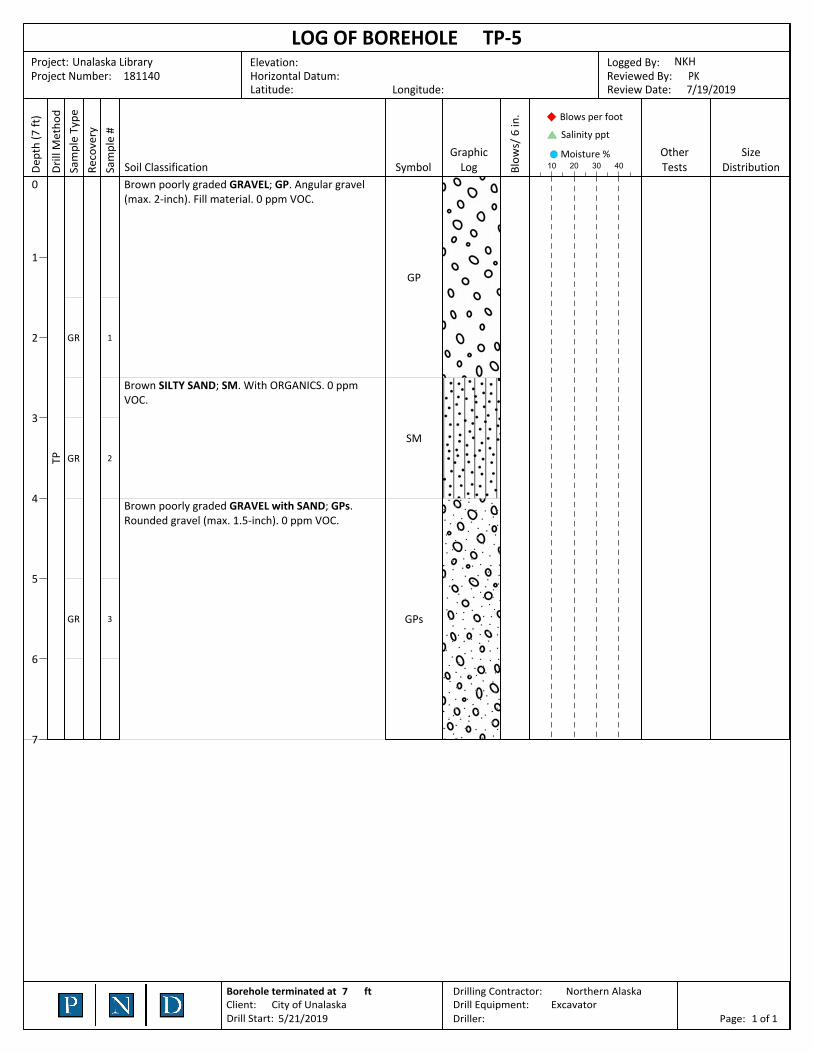
0 Brown poorly graded GRAVEL; GP. Angular gravel (max. 2-inch). Fill material. 0 ppm VOC.
Brown SILTY SAND; SM. With ORGANICS. 0 ppm VOC.
Brown poorly graded GRAVEL with SAND; GPs. Rounded gravel (max. 1.5-inch). 0 ppm VOC.
SizeDistribution
OtherTests
Moisture %40302010
Salinity ppt
Blows per foot
Blow
s/ 6
in.
GraphicLogSymbolSoil ClassificationSa
mpl
e #
Reco
very
Sam
ple
Type
Drill
Met
hod
(7 ft
)De
pth
7/19/2019Review Date:PKReviewed By:
NKHLogged By:
Longitude:Latitude:Horizontal Datum:181140Project Number:
Unalaska LibraryProject:
TP-5LOG OF BOREHOLEElevation:
11Page: ofDriller:ExcavatorDrill Equipment:
Northern AlaskaDrilling Contractor:
5/21/2019 Drill Start:City of UnalaskaClient:
ft7Borehole terminated at

PT
GPs
sGP
GPs
1GR
TP
8
7
6
5
4
3
2
1
0 PEAT; PT. Grass and topsoil.
Gray poorly graded GRAVEL with SAND; GPs. Sub-angular gravel (max. 1/2-inch). 0 ppm VOC @ 2 ft.
Light brown poorly graded SANDY GRAVEL; sGP. Rounded gravel (max. 3/4-inch). 0 ppm VOC @ 4 ft.
Light brown poorly graded GRAVEL with SAND; GPs. Rounded gravel (max. 1.5-inch). 0 ppm VOC @ 5.5 ft, 6.5 ft, and 8 ft.
SizeDistribution
OtherTests
Moisture %40302010
Salinity ppt
Blows per foot
Blow
s/ 6
in.
GraphicLogSymbolSoil ClassificationSa
mpl
e #
Reco
very
Sam
ple
Type
Drill
Met
hod
(8 ft
)De
pth
7/19/2019Review Date:PKReviewed By:
NKHLogged By:
Longitude:Latitude:Horizontal Datum:181140Project Number:
Unalaska LibraryProject:
TP-6LOG OF BOREHOLEElevation:
11Page: ofDriller:ExcavatorDrill Equipment:
Northern AlaskaDrilling Contractor:
5/21/2019 Drill Start:City of UnalaskaClient:
ft8Borehole terminated at

Gravel = 96% Sand = 4% Fines = 0%
PT
sGP
GP
1GR
TP
7
6
5
4
3
2
1
0 PEAT; PT.
Light brown poorly graded SANDY GRAVEL; sGP. Rounded gravel (max. 6-inch). With COBBLES. 0 ppm VOC @ 2 ft and 4 ft.
Light brown poorly graded GRAVEL; GP. Rounded gravel (max. 2-inch). 0 ppm VOC @ 6 ft.
SizeDistribution
OtherTests
Moisture %40302010
Salinity ppt
Blows per foot
Blow
s/ 6
in.
GraphicLogSymbolSoil ClassificationSa
mpl
e #
Reco
very
Sam
ple
Type
Drill
Met
hod
(7 ft
)De
pth
7/19/2019Review Date:PKReviewed By:
NKHLogged By:
Longitude:Latitude:Horizontal Datum:181140Project Number:
Unalaska LibraryProject:
TP-7LOG OF BOREHOLEElevation:
11Page: ofDriller:ExcavatorDrill Equipment:
Northern AlaskaDrilling Contractor:
5/21/2019 Drill Start:City of UnalaskaClient:
ft7Borehole terminated at

PT
sGP
GPs
TP
6
5
4
3
2
1
0 PEAT; PT. Grass.
Brownish gray poorly graded SANDY GRAVEL; sGP. (max. 6-inch). With WOOD and METAL scraps and trash. With COBBLES. 0 ppm VOC @ 2 ft and 4 ft.
Light brown poorly graded GRAVEL with SAND; GPs. Rounded gravel (max. 6-inch). With COBBLES. 0 ppm VOC @ 6 ft.
SizeDistribution
OtherTests
Moisture %40302010
Salinity ppt
Blows per foot
Blow
s/ 6
in.
GraphicLogSymbolSoil ClassificationSa
mpl
e #
Reco
very
Sam
ple
Type
Drill
Met
hod
(6 ft
)De
pth
7/19/2019Review Date:PKReviewed By:
NKHLogged By:
Longitude:Latitude:Horizontal Datum:181140Project Number:
Unalaska LibraryProject:
TP-8LOG OF BOREHOLEElevation:
11Page: ofDriller:ExcavatorDrill Equipment:
Northern AlaskaDrilling Contractor:
5/21/2019 Drill Start:City of UnalaskaClient:
ft6Borehole terminated at

Gravel = 71% Sand = 13% Fines = 16%
Gravel = 80% Sand = 19% Fines = 0%
PT
GWs
GM
GPs
1
2
3
GR
GR
GR
TP
8
7
6
5
4
3
2
1
0 PEAT; PT. 0 ppm VOC @ 0 ft.
Gray well-graded GRAVEL with SAND; GWs. Rounded gravel (max. 2-inch).
Light brown SILTY GRAVEL; GM. Rounded gravel (max. 1.5-inch). 0 ppm VOC @ 3 ft.
Light brown poorly graded GRAVEL with SAND; GPs. Rounded gravel (max. 2-inch). 0 ppm VOC @ 5 ft.
SizeDistribution
OtherTests
Moisture %40302010
Salinity ppt
Blows per foot
Blow
s/ 6
in.
GraphicLogSymbolSoil ClassificationSa
mpl
e #
Reco
very
Sam
ple
Type
Drill
Met
hod
(8 ft
)De
pth
7/19/2019Review Date:PKReviewed By:
NKHLogged By:
Longitude:Latitude:Horizontal Datum:181140Project Number:
Unalaska LibraryProject:
TP-9LOG OF BOREHOLEElevation:
11Page: ofDriller:ExcavatorDrill Equipment:
Northern AlaskaDrilling Contractor:
5/21/2019 Drill Start:City of UnalaskaClient:
ft8Borehole terminated at

PT
gSW
GWs
SM
GPs
1
2
3
4
GR
GR
GR
GR
TP
7
6
5
4
3
2
1
0 Brownish gray PEAT; PT.
Brownish gray well-graded GRAVELLY SAND; gSW. Rounded gravel (max. 3/4-inch). With ORGANICS. 0 ppm VOC @ 0.5 ft.
Gray well-graded GRAVEL with SAND; GWs. (max. 1-inch). 0 ppm VOC @ 2.5 ft.
Brown SILTY SAND; SM. (max. 1/2-inch). With ORGANICS. 0 ppm VOC @ 3.5 ft.
Orange-brown poorly graded GRAVEL with SAND; GPs. Sub-rounded/sub-angular gravel (max. 1-inch). 0 ppm VOC @ 6 ft.
SizeDistribution
OtherTests
Moisture %40302010
Salinity ppt
Blows per foot
Blow
s/ 6
in.
GraphicLogSymbolSoil ClassificationSa
mpl
e #
Reco
very
Sam
ple
Type
Drill
Met
hod
(7 ft
)De
pth
7/19/2019Review Date:PKReviewed By:
NKHLogged By:
Longitude:Latitude:Horizontal Datum:181140Project Number:
Unalaska LibraryProject:
TP-ALOG OF BOREHOLEElevation:
11Page: ofDriller:ExcavatorDrill Equipment:
Northern AlaskaDrilling Contractor:
5/21/2019 Drill Start:City of UnalaskaClient:
ft7Borehole terminated at

sGW
BR
1
2
GR
GR
TP
4
3
2
1
0 Brown well-graded SANDY GRAVEL; sGW. Sub-rounded/sub-angular gravel (max. 1-inch). 0 ppm VOC @ 0.5 ft.
Brown well-graded SANDY GRAVEL; sGW. Rounded gravel (max. 1/2-inch). 0 ppm VOC @ 2 ft.
BEDROCK ; BR. Boulder or bedrock.
SizeDistribution
OtherTests
Moisture %40302010
Salinity ppt
Blows per foot
Blow
s/ 6
in.
GraphicLogSymbolSoil ClassificationSa
mpl
e #
Reco
very
Sam
ple
Type
Drill
Met
hod
(4 ft
)De
pth
7/19/2019Review Date:PKReviewed By:
NKHLogged By:
Longitude:Latitude:Horizontal Datum:181140Project Number:
Unalaska LibraryProject:
TP-CLOG OF BOREHOLEElevation:
11Page: ofDriller:ExcavatorDrill Equipment:
Northern AlaskaDrilling Contractor:
5/21/2019 Drill Start:City of UnalaskaClient:
ft4Borehole terminated at

B‐1
APPENDIX B — Summary of Lab and Field Characteristics

Bo
reho
le
Samp
le #
From
To
Samp
le M
etho
d
Liqu
id Lim
it (%)
Plastic Lim
it (%)
Gravel
Sand
Fines
Gradation (%)
Max P
article Size
(in)
Salinity (p
pt)
Mo
isture
(%)
Particle
Shap
e
Particle
An
gularity
Oth
er Tests
Labo
ratory
Classificatio
n
Summary of Sample Characteristics
Project: Unalaska Library
Project #: 181140
Client: City of Unalaska
TP-6 1 1.5 2 81.3 18.0 0.0 2 5 SR-SAGPsGR
TP-7 1 4.5 5 95.9 3.9 0.0 3.5 5 SR-SAGPGR
TP-9 1 0.5 1.5 2 5 SRGWsGR
TP-9 2 2.5 3.5 71.0 12.5 16.0 2.5 19 SRGMGR
TP-9 3 5.5 6.5 80.1 19.3 0.0 2 9 SR-SAGPsGR
5 samples
Page 1 of 1

coarse finemediumcoarse fine
SANDCOBBLE GRAVEL
Grain Size Distribution
FinesSandGravel P10D50Laboratory ClassificationGradation (%)
ToFromBoreholeSample
#
US Sieve Opening (in.) US Sieve Numbers
13 #40 #100#42 1.5 ¾ ⅜ #10 #20 #60 #140 #200
Project: Unalaska Library
Project #: 181140
Client: City of Unalaska
12.719.40.018.081.321.5TP-6 GPs1
3.136.40.03.995.954.5TP-7 GP1
25.625.316.012.571.03.52.5TP-9 GM2
13.923.30.019.380.16.55.5TP-9 GPs3
Page 1 of 1