Embed Size (px)
Citation preview
GEOTECHNICAL ENGINEERING REPORT
LAKE ERIE SHORES/SLOPE STABILIZATIONEAST 233RD TO EAST 246TH STREET
EUCLID, CUYAHOGA COUNTY, OHIO
CTL PROJECT NO. 130050030CLE
PREPARED FOR:
SMITH GROUP, JJR44 EAST MIFFLIN STREET, SUITE 500
MADISON, WI. 53703
PREPARED BY:
CTL ENGINEERING, INC.3085 INTERSTATE PARKWAY
BRUNSWICK, OHIO [email protected]
May 19, 2014

TABLE OF CONTENTS
PAGE
I. PROJECT DESCRIPTION .......................................................................................... 4II. SUBSURFACE INVESTIGATION ............................................................................. 4III. FINDINGS...................................................................................................................... 5
A. Visual Observations ................................................................................................ 5B. Site Geology............................................................................................................ 7C. Subsurface Soil/Rock Conditions ........................................................................... 8
IV. ANALYSIS & RECOMMENDATIONS ..................................................................... 9A. Slope Stability Analysis:......................................................................................... 9B. Site Preparation and Earthwork: ........................................................................... 11C. Bin Walls or Sheet Pile Walls:.............................................................................. 12D. Groundwater Control: ........................................................................................... 13
V. CHANGED CONDITIONS ........................................................................................ 14VI. TESTING AND OBSERVATION.............................................................................. 14VII. CLOSURE .................................................................................................................... 14
APPENDIX A - BORING LOCATION PLANS- SHORELINE PROFILE ZONES- SOIL PROFILE
APPENDIX B - TEST BORING RECORDS
APPENDIX C - LABORATORY TESTS RESULTS
APPENDIX D- SLOPE SECTIONS PLAN- SLOPE STABILITY ANALYSIS

Geotechnical Engineering Report May 19, 2014Lake Erie Shoreline Protection – Euclid, OhioCTL Project No. 13050030CLE Page 4
I. PROJECT DESCRIPTION
This report presents the results of a subsurface investigation, slope stability analysis, andpreliminary recommendations for slope stabilization and improvement along the LakeErie shoreline between East 233rd and East 246th Street in Euclid, Cuyahoga County,Ohio.
The shoreline within the project limits is divided into 6 zones. The zones are identified Ato F and are shown on the enclosed Shoreline Profile Zones by Smith Group dated March2014 in Appendix A.
II. SUBSURFACE INVESTIGATION
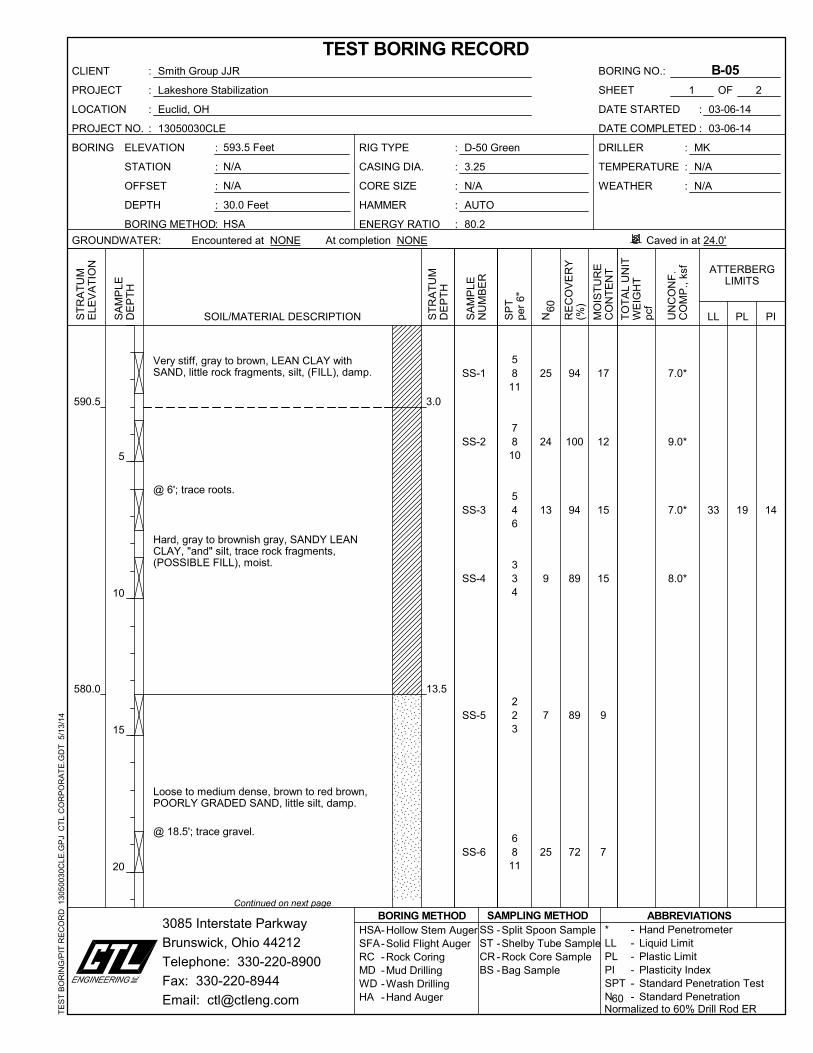
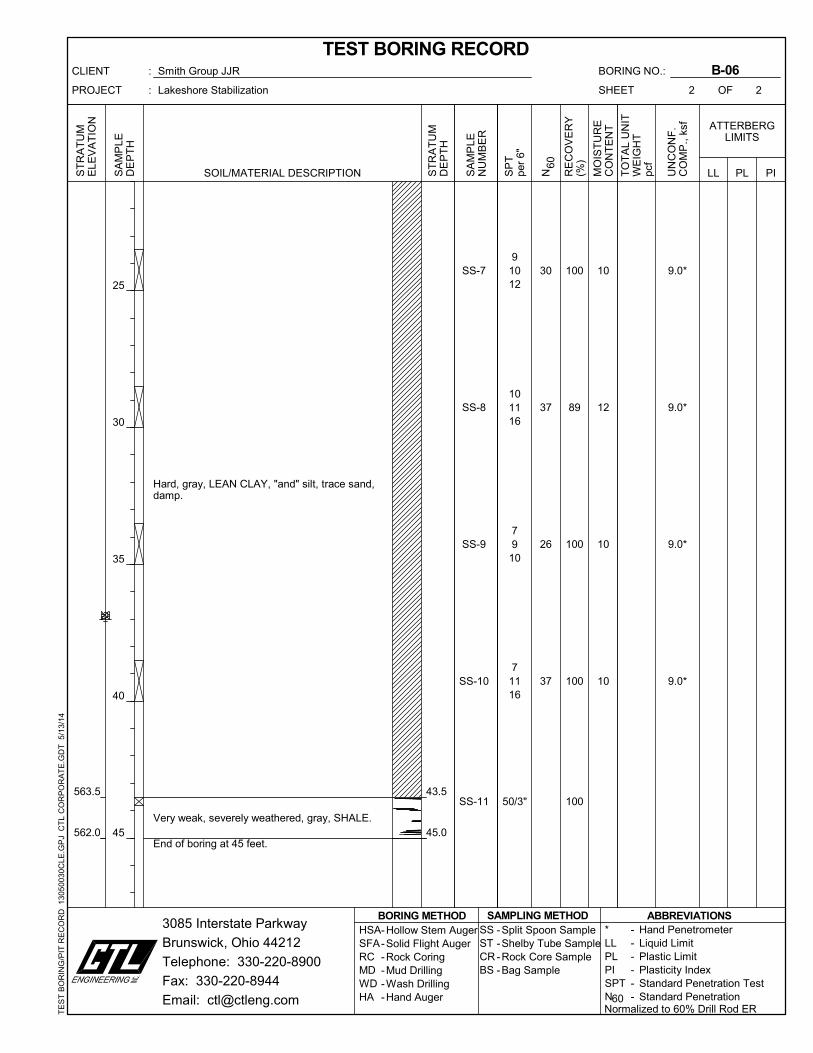
Per Smith Group JJR’s request, six (6) soil test borings, identified as B-1 to B-6, weredrilled for the investigation as follows:
Boring No. Boring Depth (ft)Location
Latitude LongitudeB-1 40.0 41ο 37' 01.9" N 81ο 31' 12.3" WB-2 40.0 41ο 37' 03.8" N 81ο 30' 58.0" WB-3 45.0 41ο 37' 04.8" N 81ο 30' 53.8" WB-4 30.0 41ο 37' 06.7" N 81ο 30' 49.9" WB-5 30.0 41ο 37' 06.3" N 81ο 30' 50.0" WB-6 45.0 41ο 37' 08.7" N 81ο 30' 42.5" W
The boring locations are also shown on the Boring Location Plan found in Appendix A ofthis report. The borings were drilled to depths ranging from 30 to 45 feet below existinggrades.
The test borings were advanced utilizing hollow-stem augers with ATV and truckmounted drill rigs. Standard Penetration Tests (SPT) were conducted in each boringdrilled using an automatic, 140-pound hammer falling 30 inches to drive a 2-inch O.D.split barrel sampler for 18 inches. The energy ratios of the two different drill rig’sautomatic hammers were 81.7 % for borings B-1, B-2, and B-6; and 80.2 % for boringsB-3, B-4 and B-5. The SPT values were obtained at 2.5-foot intervals in upper 10 feetand at 5-foot intervals thereafter.
Drilling, sampling, and field testing have been performed according to standardgeotechnical engineering practices and current ASTM procedures. Laboratory testingwas performed in our accredited laboratories by trained technicians. Results from fieldand laboratory tests are shown on the enclosed test boring records found in the AppendixB of this report.
The ground surface elevations at test boring locations were interpolated using atopographic survey provided to CTL from The Smith Group.
Geotechnical Engineering Report May 19, 2014Lake Erie Shoreline Protection – Euclid, OhioCTL Project No. 13050030CLE Page 5
All soil samples obtained from drilling operations were preserved in glass jars. Soilsamples were subject to visual classification in the field and were delivered to CTLEngineering for laboratory testing and analysis. Soil/rock samples were subjected tolaboratory testing as follows:
58 Soil and Rock Classifications. 50 Moisture Contents. 39 Pocket Penetrometer Tests. 8 Sieve and Hydrometers 8 Atterberg Limits
Boring logs, including the soil’s moisture content, Atterberg Limits, and pocketpenetrometer results are enclosed in appendix B of this report. The sieve and hydrometertests results are included in Appendix C of this report.
III. FINDINGS
A. Visual Observations
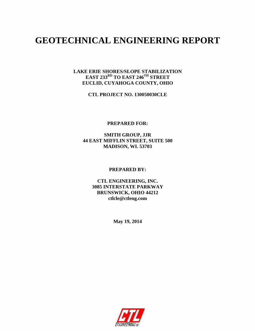
The Lake Erie Shoreline within the project limits is located along the backyard ofsingle homes, high rise, and apartment complex for residential units. Theshoreline consists of wooded and vegetation covered steep slopes. The backyardsof the residential properties consisted of relatively leveled mowed lawn withisolated trees, or parking lots for the high rise complex.
Based on our site reconnaissance, it is our opinion that the ongoing slope failuresare mostly due to shoreline erosion. The slope failures consist mostly of shallowslough mass or erosion. Evidence of random material dumping was noted alongthe slopes especially in the areas of Borings B-2 to B-5. The following photosdepict site conditions witnessed during our field investigation.
Photo 1: Evidence of Material Dumping –Zone E. Looking E. Area of Borings B-4 & B-5.

Geotechnical Engineering Report May 19, 2014Lake Erie Shoreline Protection – Euclid, OhioCTL Project No. 13050030CLE Page 6
Photo 2: Evidence of tilted trees – Looking W. to Zone D Area of Borings B-4 & B-5.
Photo 3: Evidence of tilted trees & Dumping – Zone E/F. looking W.

Geotechnical Engineering Report May 19, 2014Lake Erie Shoreline Protection – Euclid, OhioCTL Project No. 13050030CLE Page 7
Photo 4: Evidence of tilted trees & Dumping – Zone C looking W.
B. Site Geology
The project site lies within the Huron-Erie Lake Plains section of the CentralLowland Physiographic Province of Ohio. This section is characterized as theedge of a very low relief Ice Age lake basin and is separated from modern dayLake Erie by shoreline cliffs. The section contains major streams which cut intodeep gorges. (Physiographic Regions of Ohio, Brockman, Scott C., ODNRDivision of Geological Survey, 1998)
In general, the project area is characterized by the hydro-geologic setting 7F,Glacial Lake Deposits. This setting is marked by a relatively flat topography andcontains varying thicknesses of fine-grained materials overlying fracturedsedimentary rocks. The fine grained material consists of silts and clays that areinter-layered with fine sands. (Ground Water Pollution Potential of CuyahogaCounty, Ohio, Barber, Douglas J., ODNR Division of Water, April 1994)
The bedrock underlying the project area is comprised of the Devonian System,dating from 359 to 407 million years before present as defined in Ohio Divisionof Geological Survey, 2006, Bedrock geologic map of Ohio: Ohio Department ofNatural Resources, Division of Geologic Survey Map BG-1. The main unitunderlying the project area is known as the Ohio Shale. This consists of brownishblack to greenish gray shale that weathers to a brown color. The shale can becarbonaceous to clayey and can be laminated to thinly bedded. (Geologic Units of

Geotechnical Engineering Report May 19, 2014Lake Erie Shoreline Protection – Euclid, OhioCTL Project No. 13050030CLE Page 8
Cuyahoga County, 2012, Ohio, U.S. Department of the Interior, U.S. GeologicalSurvey)
In review of Topographic Map of the East Cleveland Quadrangle (7.5 MinuteSeries), dated 2013, surface elevations across the project site appear to beapproximately at 600 feet.
Maps of underground mines in the vicinity of the project site were obtained fromOhio Department of Natural Resources - Division of Mineral Resources website(www.ohiodnr.com/mineral). According to the ODNR website, there are not anymines listed in the immediate vicinity of the project area.
C. Subsurface Soil/Rock Conditions
Surface materials at boring locations B-1, B-3, and B-6 consist of about 8 to 13inches of topsoil. The surface materials at the remaining borings were part ofrandom fills.
The subsurface material at test boring locations B-2 to B-5 consisted of 12 to 28feet of random fill containing concrete, rock fragments, clay, gravel and sand.The deepest fill of 28 feet was noted in the area of Boring B-4, the fill depths atthe other borings (B-2, B-3 and B-5) was on the order of 12 to 14 feet deep.
The subsurface materials at borings B-1 and B-6 consisted of very stiff to hardnatural lean clay with varying amount of silt, sand and gravel. A 10-foot thickpocket of loose to medium dense sand was encountered at 13 feet below existinggrades within the lean clay deposits at boring B-5.
Very weak severely weathered gray shale was encountered below the fill andnatural clay deposits at all borings at depths ranging from 28 to 44 feet belowexisting grades (about elevations 571 to 563 feet).
The Standard Penetration Test (SPT, N60) and moisture content of the overburdennatural clay and sand deposits ranged from 7 to 37 (but mostly from mid teens tolow 20’s) blows per foot (bpf) and 10 to 25 % respectively.
The Standard Penetration Test (SPT, N60) and moisture content of the fill materialranged from 4 to 27 blows per foot (bpf) and 14 to 25 % respectively.
The SPT of the weathered rock was over 50 bpf.
Laboratory testing for Atterberg Limits and grain-size analysis was performed oneight cohesive samples obtained from the borings drilled. Laboratory test resultsare tabulated below.

Geotechnical Engineering Report May 19, 2014Lake Erie Shoreline Protection – Euclid, OhioCTL Project No. 13050030CLE Page 9
Table 1 - Laboratory Test Results - Atterberg Limits and Grain-Size Analysis
Boring Sample Depth (ft) USCS LL PIPercentFines*
Silt ClayB-01 SS-6 18.5 – 20.0 CL 32 15 56 42B-02 SS-7 23.5 – 25.0 CL-ML 24 6 73 14B-03 SS-4 8.5 – 10.0 CL 33 14 50 28B-03 SS-7 23.5 – 25.0 CL 48 25 29 66B-04 SS-5 13.5 – 15.0 CL 36 16 54 24B-05 SS-3 6.0 -7.5 CL 33 14 39 14B-06 SS-2 3.5 – 5.0 CL 38 19 44 31B-06 SS-6 18.5 – 20.0 CL 31 13 54 33
* Clay is defined as material particle size smaller than 0.005 mm.
For detailed subsurface conditions refer to the boring logs included in Appendix Bof this Report.
Groundwater
Groundwater was encountered during drilling only in boring B-4 at 23 feet belowexisting grades (elevation 570 feet). It should be noted that fluctuations ingroundwater levels should be expected over time due to variations inprecipitation. Static groundwater level can only be determined throughobservations made in cased holes over a long period of time. However, boringsindicate that there is an increasing chance of encountering ground water withinmore permeable granular soils and along the shale/soil interface. Groundwaterlevels typically are the highest during the spring months.
IV. ANALYSIS & RECOMMENDATIONS
A. Slope Stability Analysis:
The shoreline within the project limits is divided into 6 zones. The zones are identified Ato F and are shown on the enclosed Shoreline Profile Zones by Smith Group dated March2014 in Appendix A. Based on this zoning profile, Zones B and E top of slope mustremain in current locations. Zones A and F can be cut back. Zones C and D requiresoptimum solution or a best approach for stabilization, we believe these zones can be cutback to a limit.
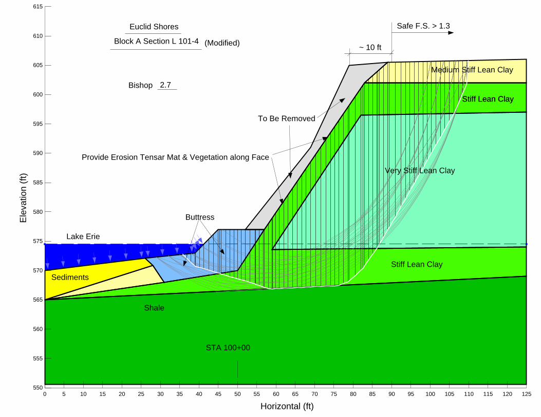
Global slope stability analysis was performed for each zone at sections noted on the planview also provide by Smith Group and are included in Appendix A of this report. Theslope stability analysis was performed with Slope/W computer software. This program isbased on two-dimensional limiting equilibrium methods in which the calculation of thefactor of safety against instability of a slope is performed by the method of slices. TheBishop method of analysis was used in analyzing over 100 surfaces of a circular shapefor each section.

Geotechnical Engineering Report May 19, 2014Lake Erie Shoreline Protection – Euclid, OhioCTL Project No. 13050030CLE Page 10
The results of the slope stability analysis in term of minimum safety factors, andproposed stabilization sections are included in Appendix D of this report and aresummarized in Table 2 below:
Table 2: Summary of Slope Stability Analysis.
Zone SectionSafety Factor
CommentsExisting Modified
A L 101-4 0.3 2.7
Adequately Stable with 10 feet cut back attop of slope, and removal of surfacesloughed material, and provision forRevetment to Elevation 577 feet.
B L 102-1 0.8 1.1
Still not quite adequately stable withRevetment to Elevation 577, and with morethan 50% in place random fill improvement.Consider similar section to Zone E.
C&D L 103-1 0.7 1.1
Surface material still not quite adequatelystable with Revetment to Elevation 580, and30 feet top of slope cut back. Considersimilar section to Zone E.
E L 103-4 0.5-1.1 1.6Adequately stable with Revetment toelevation 585.
F L 104-4 3.0 N/A
Adequately stable as is, requires onlyerosion control using Revetment at the toe,and deep root vegetation with erosion tensarmat along the face of slopes.
The subsurface information was limited to borings B-1 to B-6 which are located at thetop of the existing slopes. There were no borings taking in Zone B, we assumed boringB-2 to be representative of the subsurface material of this zone. The subsurfaceconditions over the slopes and at the toe are not known, we made certain assumptionbased on visual observation when developing the soil profile along each analyzed crosssection.
The proposed fill material for the revetments is also not identified at this time. For thepurpose of our analysis we have assumed that the revetment will consists of armored faceand large well graded material of cobble and gravel size ranging from 3 to 12 inches orlarger within the wave zone, and coarse aggregate above the wave zone with assumedand angle of internal friction of 38ο . Once the revetment material is identified, and if notfound to be within the limit of our assumptions, then CTL should be notified and giventhe opportunity to revise our recommendations.
We anticipate the revetment to be constructed per project specifications at a slope of2H:1V. Steeper sloped revetments at 1H:1V or 1.5H:1V can be considered but withGeogrid reinforcement. Vertical or Tapered Bin Walls or sheet piles with tie backs can

Geotechnical Engineering Report May 19, 2014Lake Erie Shoreline Protection – Euclid, OhioCTL Project No. 13050030CLE Page 11
also be considered as substitute to revetments. Recommendations for the design of theseretaining structures are provided in Section C below.
B. Site Preparation and Earthwork:
The site preparation and fill placement should be accomplished in accordance withour outlined recommendations as follows:
1. All vegetative matter, trees, tree stumps, and topsoil and organically contaminatedmaterial encountered within the proposed construction limits should be removedfrom the site. Topsoil may be stockpiled off the site to be reused as the toppinglayer.
2. All sloughed material should be removed and conditioned to be reused orincorporated into the new fill or hauled off the site. Based on visual observation,the exposed grades of sloughed areas after topsoil removal are expected to be softto medium stiff and above optimum moisture content. Large concrete slabs orconcrete blocks should be processed and should not be incorporated within theengineered fill portion, such material may be reused in conjunction with therevetment armor units.
3. During earthwork operations, care should be taken to provide adequate drainageon the surface of exposed soils. Absorption of heavy rainfall, accumulations ofwater and heavy construction traffic may result in softening of these soils, hence,severely weakening the strength of the subgrade soils. Seepage zones should beintercepted and allowed to freely drain without compromising the stability of theslopes/new fill.
4. Temporary excavations in excess of 4 feet in depth should be sloped, benched orshored in accordance with OHSA regulations. Excavation sidewalls for anyunderground utility placements or incidental retaining walls, should be laid backat a slope rate no steeper than 1.5:1 (Horizontal to Vertical).
5. Following acceptance of the exposed surfaces, all fill materials required to buildthe slope and revetments should consist of clean, on-site, inorganic, non-frozensoils. Topsoil, frozen and/or organically contaminated soils are not consideredsuitable for use as fill. All fill materials should be observed, tested and approvedby the Soils Engineering Technician under the direction of the GeotechnicalEngineer.
6. Engineered fill should be placed in layers not to exceed 8 inches in loosethickness, with each layer compacted to 98 percent of the maximum dry densityas determined by ASTM D-698 Standard Proctor method (AASHTO T-99) and at3% of its optimum moisture content.
7. All exposed soil slopes should not be steeper than 2H:1V and be vegetated toprevent erosion. Steeper slopes can be considered but requires geogrid

Geotechnical Engineering Report May 19, 2014Lake Erie Shoreline Protection – Euclid, OhioCTL Project No. 13050030CLE Page 12
reinforcements. Surface runoff and drainage should be designed to limit erosionof surface grades. Rock channels or similar items are recommended in areas ofexpected high volume runoff.
8. Provide filter fabric as separator between open graded or large size material andfine to coarse graded material to prevent migration of particle. Separating fabricplaced directly on large size (cobble) may be subject to tear, therefore the largesize material should be gradually transitioned to smaller size aggregate so toestablish a uniform contact with the separating fabric.
9. Where new embankment fill materials will be placed on or adjacent to existingslopes that are steeper than 8H:1V should be continuously benched or benched asdeemed practical over those areas. Benching should be of sufficient width topermit operations of placing and compacting equipment. Bench the slope as theembankment is placed and compact each layer. Begin each bench at theintersection of the existing slope and the vertical cut of the previous bench. Re-compact the cut materials along with the embankment.
Figure 1. - Diagram of Soil Bench
10. Provide tensar erosion mat and erosion protection consisting of deep rooted planton all exposed slopes of fine grained material
C. Bin Walls or Sheet Pile Walls:
It is understood that two types of walls, Bin walls or sheet pile walls with tie backsmay be considered as a substitute to revetments or where space is limited and mayprohibit the construction of revetments.
The walls are expected to be positioned at the toes near the Lake Erie water level.The subsurface conditions at the toe of slopes are not known. Based on visualobservation, we anticipate either shale outcrops, sediments, concrete debris/slabs, ormedium stiff to very stiff natural soil overburden material. The bin walls should beextended to bear into stiff to very stiff natural deposits or weathered shale. The binwalls bearing material surfaces should be firm; free of loose sediment materials,water, and frost; and inspected and approved by the Geotechnical Engineer. Thesheet pile walls should be driven into the shale with tie backs also anchored into theshale.

Geotechnical Engineering Report May 19, 2014Lake Erie Shoreline Protection – Euclid, OhioCTL Project No. 13050030CLE Page 13
For the purpose of preliminary design and budgeting we suggest using the designparameters summarized in Table 3 below.
Table 3. Bin or Sheet Pile Walls - Design parameters
Soil ParametersRetained Medium Bearing Medium
Onsite Clay Onsite Fill Stiff Clay Shale
Average Cohesion, (c, psf) Ignore Ignore 1,500 5,500
Angle of Internal Friction (фο) 18 27 22 14
Total Unit Weight, pcf 125 120 125 145
At Rest Earth Pressure Coefficient (K0) 0.64 0.55 0.64 N/A
Active Earth Pressure Coefficient (Ka) 0.53 0.38 0.46 N/A
Passive Earth Pressure Coefficient (Kp) N/A N/A Ignore 1.64
Allowable Bearing Pressure, psf N/A N/A 2,500 16,000
The at rest earth pressure parameters for clay was based on the soils Plasticity Indexassuming normally consolidated clay. The active and passive earth pressure parametersprovided above are based on Rankine assuming horizontal backfill. In order to account forsloped backfill above the wall, we recommend adding 1/2 of the slope above the wall to thewall height. Passive resistance within shale should take into account the cohesion term perRankine’s procedure. The tie backs into the shale should be designed based on an averageadhesion of 2,500 psf. Passive resistance in the upper 5 feet or within erodible zones abovethe shale should be ignored.
D. Groundwater Control:
Depending upon the time of year and the precipitation rates preceding construction,seepage water could be encountered. Groundwater seepage is generally associatedwith water trapped within granular layers interbedded within a mostly cohesive soilprofile or along the rock/soil interface. These layers are typically discontinuous andare recharged by precipitation events. Excavations that encounter these layers willlikely encounter at least some groundwater. Temporary dewatering in areas ofseepage water may be accomplished by placing localized sumps within theexcavation or in sumps beyond the excavation. Permanent dewatering where requiredshould be accomplished by perforated drains, drainage blankets or chimney drains.Seepage rates are difficult to predict and flow from sand seams could be significantand may or may not diminish with time. Care should be taken to avoid over pumpingand removal of fines.
Backfill placed directly behind walls should consist of free draining granular material.The backfill should be compacted using compaction techniques and equipmentapproved by the Geotechnical Engineer. Perforated pipe drains should be installedalong the base of the walls where applicable slightly above the Lake Erie Water Levelto prevent the accumulation of water which would increase lateral loads. Analternative to perforated drain is the use of weep holes.

Geotechnical Engineering Report May 19, 2014Lake Erie Shoreline Protection – Euclid, OhioCTL Project No. 13050030CLE Page 14
V. CHANGED CONDITIONS
The evaluations, conclusions, and recommendations in this report are based on ourinterpretation of the field and laboratory data obtained during the exploration, ourunderstanding of the project and our experience with similar sites and subsurfaceconditions using generally accepted geotechnical engineering practices. Althoughindividual test borings are representative of the subsurface conditions at the boringlocations on the dates drilled, they are not necessarily representative of the subsurfaceconditions between boring locations or subsurface conditions during other seasons of theyear.
In the event that changes in the project are proposed, additional information becomesavailable, or if it is apparent that subsurface conditions are different from those providedin this report, CTL Engineering should be notified so that our recommendations can bemodified, if required.
VI. TESTING AND OBSERVATION
During the design process, it is recommended that CTL Engineering work with theproject designers to confirm that the geotechnical recommendations are properlyincorporated into the final plans and specifications, and to assist with establishing criteriafor the construction observation and testing.
CTL Engineering is not responsible for independent conclusions, opinions andrecommendations made by others based on the data and recommendations provided inthis report. It is recommended that CTL be retained to provide construction qualitycontrol services on this project. If CTL Engineering is not retained for these services,CTL shall assume no responsibility for compliance with the design concepts orrecommendations provided.
VII. CLOSURE
This report has been prepared for the exclusive use of Smith Group for use only on thisproject. Our services have been performed in accordance with generally acceptedGeotechnical Engineering principles and practices. No warranty is either expressed orimplied.
The report addresses only the geotechnical issues and therefore, does not includeenvironmental issues such as the presence or absence of hazardous or toxic materials atthe project site.
Recommendations provided herein were developed from information obtained from fieldinvestigations, laboratory testing, information provided by client and/or theirrepresentatives or consultants, as well as analysis by CTL Engineering personnel.

Geotechnical Engineering Report May 19, 2014Lake Erie Shoreline Protection – Euclid, OhioCTL Project No. 13050030CLE Page 15
Specific design and construction recommendations have been provided in varioussections of the report. Therefore, the report should be used in its entirety.
Thank you for the opportunity to be of service to you on this project. If you have anyquestions regarding our services, please contact our office.
Respectfully Submitted,CTL ENGINEERING, INC.
Matthew Kairouz, P.E.Project Engineer

APPENDIX A
BORING LOCATION PLAN SHORELINE PROFILE ZONES SOIL PROFILE

Date
5/19/2014
CTL ENGINEERING, INC. Scale
GEOTECHNICAL ENGINEERS None
TESTING * INSPECTION Drawn By Reviewed By Page Project No.
LABORATORY SERVICES MK 1 of 1 13050030CLE
Euclid, Cuyahoga County, Ohio
BORING LOCATION MAPSmith Group
Lake Erie - Euclid Shoreline
Between E. 233rd & E. 246th Streets

MARCH, 2014
1
SHORELINE PROFILE ZONESEUCLID PHASE IV SHORELINE ENHANCEMENTS
SIMS PARK
200’1000’ 400’
E 242nd
1
1
2
3
4
5
6
AB
C
DE
F
LEGEND
BORING LOCATION
SHORELINE ZONES: TOP OF BANK CONSTRAINTS
CAN BE CUT BACK
MUST REMAIN IN CURRENT LOCATION
DETERMINE BEST APPROACH

560
565
570
575
580
585
590
595
600
605
610
560
565
570
575
580
585
590
595
600
605
610
50/2"
50/3.5"
26
20
16
17
15
19
22
18
11
4
12
22
25
15
14
15
15
B-01
50/1"
35
15
15
18
17
18
9
15
19
18
27
19
22
26
18
33
B-02
50/3"
19
14
15
21
22
2516
18
13
11
9
15
20
20
11
11
17
17
23
23
32
B-03
50/5.5"
50/5.75"
13
25
24
13
20
15
20
4
7
35
B-04
50/6"
17
12
15
15
9
7
11
25
24
13
9
7
25
24
B-05
50/3"
21
20
15
15
14
16
10
12
10
10
8
8
12
18
23
20
30
37
26
37
B-06
SW-SMASPHALT
GW
GP-GC
GC-GM
GP-GM
Brunswick, Ohio 44212
GW-GC
SW-SC ML
SC
SC-SM
SOIL PLAN/PROFILEDATE
5/13/2014
PAGE
1 OF 1 13050030CLEPROJECT NUMBER
CTL ENGINEERING, INC.CONSULTING ENGINEERSTOPSOIL
N STANDARD PENETRATION INBLOWS PER FOOT (N)
DRAWN BY
MOISTURE CONTENT INPERCENT (w)
GROUND WATER DURINGDRILLING
Euclid, OHGROUND WATER AT "N"HOURS AFTER COMPLETION
Smith Group JJRGP CL
OL
B-01
CL-ML SHALE
SP-SM
LIMESTONE
GW-GM
GM
SP
SP-SC
SMMK
GROUND WATER ATCOMPLETION OF DRILLING Lakeshore Stabilization
W
LEGEND
SCALEAS SHOWN
FILL
CH
MH
OH
PTGC
SW
3085 Interstate Parkway
SILTSTONE

APPENDIX B
TEST BORING RECORDS
�
��
��
��
��
��
��
� �� �� �� �� �� �� �� � � ��� ���
�������������
�����������
�����������
�� ��
��������
�� �� ��
��������
��������
�
�

SOIL DESCRIPTION
NON-COHESIVE STANDARD PENETRATION
SOIL DESCRIPTION BLOWCOUNTS PER FOOT (bpf)
Very Loose 0 – 4
Loose 5 – 10
Medium Dense 11 – 30
Dense 31 – 50
Very Dense Over 50
COHESIVE SOIL STANDARD PENETRATION
DESCRIPTION BLOWCOUNTS PER FOOT (bpf)
Very Soft 0 – 1
Soft 2 – 4
Medium Stiff 5 – 8
Stiff 9 – 15
Very Stiff 16 – 30
Hard Over 30
GRADATION
COMPONENT SIZE
Boulders Larger Than 8”
Cobbles 8” – 3”
Coarse Gravel Passing 3” Retained on ¾”
Fine Gravel Passing ¾” Retained on #10
Coarse Sand Passing #10 Retained #40
Fine Sand Passing #40 Retained on #200
Silt 0.074 mm to 0.005 mm
Clay Smaller Than 0.005 mm
COMPONENT
MODIFIERS SIZE
Trace > 0 – 10%
Little 11 – 20%
Some 21 – 35%
And 36 – 50%
MOISTURE
TERMS DESCRIPTION
Dry Powdery
Damp Below Plastic Limit
Moist Above Plastic Limit, Below Liquid Limit
Wet Above Liquid Limit

32 17 15
8" TOPSOIL
@ 1'; Slightly organic.
Stiff to very stiff, light brown to mottled gray andlight brown, LEAN CLAY, some silt, trace roots,moist.
@ 8.5'; Trace rock fragments.
Hard, grayish brown, LEAN CLAY, some silt,moist.
Hard to very stiff, gray, LEAN CLAY, "and" silt,damp to moist.
0.5
6.0
13.5
SS-1
SS-2
SS-3
SS-4
SS-5
SS-6
1124
345
379
6711
765
346
100
100
83
100
100
100
2.5*
5.5*
9.0*
9.0*
9.0*
4.0*
26
20
16
17
15
19
602.5
597.0
589.5
4
12
22
25
15
14
DATE STARTED
DATE COMPLETED
03-06-14
03-06-14
:
:
ELEVATION
STATION
OFFSET
DEPTH
BORING METHOD
603.0 Feet
N/A
N/A
40.0 Feet
HSA
:
:
:
:
:
MK
N/A
N/A
RIG TYPE
CASING DIA.
CORE SIZE
HAMMER
ENERGY RATIO
:
:
:
:
:
:
:
:
Euclid, OH
13050030CLE
DRILLER
TEMPERATURE
WEATHER
LOCATION
PROJECT NO.
:
:
BORING D-50 Red Truck
3.25
N/A
AUTO
81.7
GROUNDWATER: Encountered at NONE At completion NONE Caved in at 31.0'
SP
Tpe
r 6"
N
B-01
5
10
15
20
------60
*LLPLPISPTN
Continued on next page
2
Normalized to 60% Drill Rod ER
OF
BORING NO.:
SHEETS
TR
AT
UM
ELE
VA
TIO
N
SA
MP
LED
EP
TH
SOIL/MATERIAL DESCRIPTION MO
IST
UR
EC
ON
TE
NT
TO
TA
L U
NIT
WE
IGH
Tpc
f
UN
CO
NF
.C
OM
P.,
ksf
LL PL PI
ATTERBERGLIMITS
RE
CO
VE
RY
(%)
ST
RA
TU
MD
EP
TH
SA
MP
LEN
UM
BE
R
60
TEST BORING RECORDCLIENT
PROJECT
:
:
Smith Group JJR
Lakeshore Stabilization
HSASFARCMDWDHA
------
BORING METHODSSSTCRBS
----
Hollow Stem AugerSolid Flight AugerRock CoringMud DrillingWash DrillingHand Auger
SAMPLING METHOD ABBREVIATIONS
1
Split Spoon SampleShelby Tube SampleRock Core SampleBag Sample
Hand PenetrometerLiquid LimitPlastic LimitPlasticity IndexStandard Penetration TestStandard Penetration
3085 Interstate Parkway
Brunswick, Ohio 44212
Telephone: 330-220-8900
Fax: 330-220-8944
Email: [email protected]
TE
ST
BO
RIN
G/P
IT R
EC
OR
D 1
305
0030
CLE
.GP
J C
TL
CO
RP
OR
AT
E.G
DT
5/1
3/14

Hard to very stiff, gray, LEAN CLAY, "and" silt,damp to moist.
@ 24'; 2" sand seam.
Medium dense, gray, SILTY CLAY, little sand,moist.
Very stiff, gray, LEAN CLAY, some silt, tracerock fragments, sand, moist.
Hard, gray, LEAN CLAY with SAND, "and" silt,trace rock fragments, damp.
Very weak, severely weathered, gray, SHALE,damp.
End of boring at 40 feet.
23.5
26.8
31.8
34.0
40.0
SS-7
SS-8
SS-9
SS-10
456
456
650/2"
50/3.5"
100
100
62
21
6.0*
9.0*
22
18
11
579.5
576.3
571.3
569.0
563.0
15
15
SP
Tpe
r 6"
N
B-01
25
30
35
40
45
------60
*LLPLPISPTN
2
Normalized to 60% Drill Rod ER
OF
BORING NO.:
SHEETS
TR
AT
UM
ELE
VA
TIO
N
SA
MP
LED
EP
TH
SOIL/MATERIAL DESCRIPTION MO
IST
UR
EC
ON
TE
NT
TO
TA
L U
NIT
WE
IGH
Tpc
f
UN
CO
NF
.C
OM
P.,
ksf
LL PL PI
ATTERBERGLIMITS
RE
CO
VE
RY
(%)
ST
RA
TU
MD
EP
TH
SA
MP
LEN
UM
BE
R
60
TEST BORING RECORDCLIENT
PROJECT
:
:
Smith Group JJR
Lakeshore Stabilization
HSASFARCMDWDHA
------
BORING METHODSSSTCRBS
----
Hollow Stem AugerSolid Flight AugerRock CoringMud DrillingWash DrillingHand Auger
SAMPLING METHOD ABBREVIATIONS
2
Split Spoon SampleShelby Tube SampleRock Core SampleBag Sample
Hand PenetrometerLiquid LimitPlastic LimitPlasticity IndexStandard Penetration TestStandard Penetration
3085 Interstate Parkway
Brunswick, Ohio 44212
Telephone: 330-220-8900
Fax: 330-220-8944
Email: [email protected]
TE
ST
BO
RIN
G/P
IT R
EC
OR
D 1
305
0030
CLE
.GP
J C
TL
CO
RP
OR
AT
E.G
DT
5/1
3/14

Medium stiff, black, SILTY SAND, some brick,glass, wood, little gravel, slightly organic, (FILL),moist.
Layered concrete, (FILL).
Very stiff, grayish brown, SILTY CLAY, "and"concrete fragments, (FILL), damp.
Very stiff to hard, gray, LEAN CLAY, some silt,trace rock fragments, sand, damp to moist.
3.3
8.5
14.0
SS-1
SS-2
SS-3
SS-4
SS-5
SS-6
10564
568
467
14128
468
679
44
6
6
6
100
100
7.0*
9.0*
35
15
15
18
601.8
596.5
591.0
15
19
18
27
19
22
DATE STARTED
DATE COMPLETED
03-06-14
03-06-14
:
:
ELEVATION
STATION
OFFSET
DEPTH
BORING METHOD
605.0 Feet
N/A
N/A
40.0 Feet
HSA
:
:
:
:
:
MK
N/A
N/A
RIG TYPE
CASING DIA.
CORE SIZE
HAMMER
ENERGY RATIO
:
:
:
:
:
:
:
:
Euclid, OH
13050030CLE
DRILLER
TEMPERATURE
WEATHER
LOCATION
PROJECT NO.
:
:
BORING D-50 Red Truck
3.25
N/A
AUTO
81.7
GROUNDWATER: Encountered at NONE At completion NONE Caved in at 33.0'
SP
Tpe
r 6"
N
B-02
5
10
15
20
------60
*LLPLPISPTN
Continued on next page
2
Normalized to 60% Drill Rod ER
OF
BORING NO.:
SHEETS
TR
AT
UM
ELE
VA
TIO
N
SA
MP
LED
EP
TH
SOIL/MATERIAL DESCRIPTION MO
IST
UR
EC
ON
TE
NT
TO
TA
L U
NIT
WE
IGH
Tpc
f
UN
CO
NF
.C
OM
P.,
ksf
LL PL PI
ATTERBERGLIMITS
RE
CO
VE
RY
(%)
ST
RA
TU
MD
EP
TH
SA
MP
LEN
UM
BE
R
60
TEST BORING RECORDCLIENT
PROJECT
:
:
Smith Group JJR
Lakeshore Stabilization
HSASFARCMDWDHA
------
BORING METHODSSSTCRBS
----
Hollow Stem AugerSolid Flight AugerRock CoringMud DrillingWash DrillingHand Auger
SAMPLING METHOD ABBREVIATIONS
1
Split Spoon SampleShelby Tube SampleRock Core SampleBag Sample
Hand PenetrometerLiquid LimitPlastic LimitPlasticity IndexStandard Penetration TestStandard Penetration
3085 Interstate Parkway
Brunswick, Ohio 44212
Telephone: 330-220-8900
Fax: 330-220-8944
Email: [email protected]
TE
ST
BO
RIN
G/P
IT R
EC
OR
D 1
305
0030
CLE
.GP
J C
TL
CO
RP
OR
AT
E.G
DT
5/1
3/14

24 18 6
Very stiff to hard, gray, LEAN CLAY, some silt,trace rock fragments, sand, damp to moist.
Medium dense, gray, SILTY CLAY, little sand,moist.
Hard, gray, LEAN CLAY, "and" silt, moist.
Hard gray, LEAN CLAY with SAND, some silt,trace rock fragments, damp.
Very weak, severely weathered, gray, SHALE,some clay, silt, damp.
End of boring at 40 feet.
23.5
28.5
31.8
34.0
40.0
SS-7
SS-8
SS-9
SS-10
12109
467
61212
1650/1"
100
100
100
56
8.5*
9.0*
17
18
9
581.5
576.5
573.3
571.0
565.0
26
18
33
SP
Tpe
r 6"
N
B-02
25
30
35
40
45
------60
*LLPLPISPTN
2
Normalized to 60% Drill Rod ER
OF
BORING NO.:
SHEETS
TR
AT
UM
ELE
VA
TIO
N
SA
MP
LED
EP
TH
SOIL/MATERIAL DESCRIPTION MO
IST
UR
EC
ON
TE
NT
TO
TA
L U
NIT
WE
IGH
Tpc
f
UN
CO
NF
.C
OM
P.,
ksf
LL PL PI
ATTERBERGLIMITS
RE
CO
VE
RY
(%)
ST
RA
TU
MD
EP
TH
SA
MP
LEN
UM
BE
R
60
TEST BORING RECORDCLIENT
PROJECT
:
:
Smith Group JJR
Lakeshore Stabilization
HSASFARCMDWDHA
------
BORING METHODSSSTCRBS
----
Hollow Stem AugerSolid Flight AugerRock CoringMud DrillingWash DrillingHand Auger
SAMPLING METHOD ABBREVIATIONS
2
Split Spoon SampleShelby Tube SampleRock Core SampleBag Sample
Hand PenetrometerLiquid LimitPlastic LimitPlasticity IndexStandard Penetration TestStandard Penetration
3085 Interstate Parkway
Brunswick, Ohio 44212
Telephone: 330-220-8900
Fax: 330-220-8944
Email: [email protected]
TE
ST
BO
RIN
G/P
IT R
EC
OR
D 1
305
0030
CLE
.GP
J C
TL
CO
RP
OR
AT
E.G
DT
5/1
3/14

33 19 14
10" TOPSOIL
Very stiff, grayish brown, LEAN CLAY, somesilt, trace sand, root hairs, (FILL), moist.
@ 6.0'; Cobble, petroleum odor
Very stiff, gray, LEAN CLAY with SAND, "and"silt, (FILL), damp to moist.
Very stiff, mottled gray and brown, LEAN CLAY,"and" silt, trace sand, moist.
Stiff, dark gray, LEAN CLAY with SAND, somesilt, trace root hairs, moderately organic, moist.SS-6A LOI = 7.2%
Very stiff, gray, LEAN CLAY, some silt, woodfragments, damp.Very stiff, gray, LEAN CLAY, some silt, traceroot hairs, moist.
0.8
3.5
11.8
16.8
19.3
20.0
SS-1
SS-2
SS-3
SS-4
SS-5
SS-6
347
569
778
335
344
467
89
83
17
67
78
100
7.0*
7.0*
5.0*
5.0*
6.0*
3.0*6.0*
19
14
15
21
22
2516
605.7
603.0
594.7
589.7
587.2
586.5
15
20
20
11
11
17
DATE STARTED
DATE COMPLETED
03-06-14
03-06-14
:
:
ELEVATION
STATION
OFFSET
DEPTH
BORING METHOD
606.5 Feet
N/A
N/A
45.0 Feet
HSA
:
:
:
:
:
MK
N/A
N/A
RIG TYPE
CASING DIA.
CORE SIZE
HAMMER
ENERGY RATIO
:
:
:
:
:
:
:
:
Euclid, OH
13050030CLE
DRILLER
TEMPERATURE
WEATHER
LOCATION
PROJECT NO.
:
:
BORING D-50 Green
3.25
N/A
AUTO
80.2
GROUNDWATER: Encountered at NONE At completion NONE Caved in at 36.0'
SP
Tpe
r 6"
N
B-03
5
10
15
20
------60
*LLPLPISPTN
Continued on next page
2
Normalized to 60% Drill Rod ER
OF
BORING NO.:
SHEETS
TR
AT
UM
ELE
VA
TIO
N
SA
MP
LED
EP
TH
SOIL/MATERIAL DESCRIPTION MO
IST
UR
EC
ON
TE
NT
TO
TA
L U
NIT
WE
IGH
Tpc
f
UN
CO
NF
.C
OM
P.,
ksf
LL PL PI
ATTERBERGLIMITS
RE
CO
VE
RY
(%)
ST
RA
TU
MD
EP
TH
SA
MP
LEN
UM
BE
R
60
TEST BORING RECORDCLIENT
PROJECT
:
:
Smith Group JJR
Lakeshore Stabilization
HSASFARCMDWDHA
------
BORING METHODSSSTCRBS
----
Hollow Stem AugerSolid Flight AugerRock CoringMud DrillingWash DrillingHand Auger
SAMPLING METHOD ABBREVIATIONS
1
Split Spoon SampleShelby Tube SampleRock Core SampleBag Sample
Hand PenetrometerLiquid LimitPlastic LimitPlasticity IndexStandard Penetration TestStandard Penetration
3085 Interstate Parkway
Brunswick, Ohio 44212
Telephone: 330-220-8900
Fax: 330-220-8944
Email: [email protected]
TE
ST
BO
RIN
G/P
IT R
EC
OR
D 1
305
0030
CLE
.GP
J C
TL
CO
RP
OR
AT
E.G
DT
5/1
3/14

48 23 25Very stiff, gray, LEAN CLAY, some silt, traceroot hairs, moist.
Very stiff to hard, gray, LEAN CLAY with SAND,some silt, little rock fragments, damp.
@ 38.5'; some rock fragments.
Very weak, severely weathered, gray, SHALE.
End of boring at 45 feet.
28.5
43.5
45.0
SS-7
SS-8
SS-9
SS-10
SS-11
358
6710
689
61014
50/3"
100
100
100
100
25
6.5*
7.5*
9.0*
9.0*
18
13
11
9
578.0
563.0
561.5
17
23
23
32
SP
Tpe
r 6"
N
B-03
25
30
35
40
45
------60
*LLPLPISPTN
2
Normalized to 60% Drill Rod ER
OF
BORING NO.:
SHEETS
TR
AT
UM
ELE
VA
TIO
N
SA
MP
LED
EP
TH
SOIL/MATERIAL DESCRIPTION MO
IST
UR
EC
ON
TE
NT
TO
TA
L U
NIT
WE
IGH
Tpc
f
UN
CO
NF
.C
OM
P.,
ksf
LL PL PI
ATTERBERGLIMITS
RE
CO
VE
RY
(%)
ST
RA
TU
MD
EP
TH
SA
MP
LEN
UM
BE
R
60
TEST BORING RECORDCLIENT
PROJECT
:
:
Smith Group JJR
Lakeshore Stabilization
HSASFARCMDWDHA
------
BORING METHODSSSTCRBS
----
Hollow Stem AugerSolid Flight AugerRock CoringMud DrillingWash DrillingHand Auger
SAMPLING METHOD ABBREVIATIONS
2
Split Spoon SampleShelby Tube SampleRock Core SampleBag Sample
Hand PenetrometerLiquid LimitPlastic LimitPlasticity IndexStandard Penetration TestStandard Penetration
3085 Interstate Parkway
Brunswick, Ohio 44212
Telephone: 330-220-8900
Fax: 330-220-8944
Email: [email protected]
TE
ST
BO
RIN
G/P
IT R
EC
OR
D 1
305
0030
CLE
.GP
J C
TL
CO
RP
OR
AT
E.G
DT
5/1
3/14

36 20 16
Medium dense, brown, POORLY GRADEDGRAVEL, little clay, sand, silt, (FILL), damp.
Medium dense, gray, CONCRETE fragments,(FILL).
@5'-6' concrete slab.
Medium stiff, SANDY LEAN CLAY withGRAVEL, some silt, (FILL), moist.
Medium stiff, mottled gray and brown, LEANCLAY with SAND, "and" silt, (FILL), moist.
Very dense, gray, SLAG, some brick, sand,(FILL), damp.
3.5
8.5
11.8
18.5
SS-1
SS-2
SS-3
SS-4
SS-5
SS-6
6510
1183
19114
212
232
2850/5.5"
28
28
22
67
72
52
1.5*
13
25
24
589.0
584.0
580.8
574.0
20
15
20
4
7
DATE STARTED
DATE COMPLETED
03-06-14
03-06-14
:
:
ELEVATION
STATION
OFFSET
DEPTH
BORING METHOD
592.5 Feet
N/A
N/A
30.0 Feet
HSA
:
:
:
:
:
MK
N/A
N/A
RIG TYPE
CASING DIA.
CORE SIZE
HAMMER
ENERGY RATIO
:
:
:
:
:
:
:
:
Euclid, OH
13050030CLE
DRILLER
TEMPERATURE
WEATHER
LOCATION
PROJECT NO.
:
:
BORING D-50 Green
3.25
N/A
AUTO
80.2
GROUNDWATER: Encountered at 23.5' At completion 23.0' Caved in at 25.0'
SP
Tpe
r 6"
N
B-04
5
10
15
20
------60
*LLPLPISPTN
Continued on next page
2
Normalized to 60% Drill Rod ER
OF
BORING NO.:
SHEETS
TR
AT
UM
ELE
VA
TIO
N
SA
MP
LED
EP
TH
SOIL/MATERIAL DESCRIPTION MO
IST
UR
EC
ON
TE
NT
TO
TA
L U
NIT
WE
IGH
Tpc
f
UN
CO
NF
.C
OM
P.,
ksf
LL PL PI
ATTERBERGLIMITS
RE
CO
VE
RY
(%)
ST
RA
TU
MD
EP
TH
SA
MP
LEN
UM
BE
R
60
TEST BORING RECORDCLIENT
PROJECT
:
:
Smith Group JJR
Lakeshore Stabilization
HSASFARCMDWDHA
------
BORING METHODSSSTCRBS
----
Hollow Stem AugerSolid Flight AugerRock CoringMud DrillingWash DrillingHand Auger
SAMPLING METHOD ABBREVIATIONS
1
Split Spoon SampleShelby Tube SampleRock Core SampleBag Sample
Hand PenetrometerLiquid LimitPlastic LimitPlasticity IndexStandard Penetration TestStandard Penetration
3085 Interstate Parkway
Brunswick, Ohio 44212
Telephone: 330-220-8900
Fax: 330-220-8944
Email: [email protected]
TE
ST
BO
RIN
G/P
IT R
EC
OR
D 1
305
0030
CLE
.GP
J C
TL
CO
RP
OR
AT
E.G
DT
5/1
3/14

Dense, grey, POORLY GRADED GRAVEL withsand, (FILL), damp.
Very weak, severely weathered, gray, SHALE,some clay, silt, damp.
End of boring at 30 feet.
21.8
28.5
30.0
SS-7
SS-8
81511
1050/5.75"
56
63
13
570.8
564.0
562.5
35
SP
Tpe
r 6"
N
B-04
25
30
35
40
45
------60
*LLPLPISPTN
2
Normalized to 60% Drill Rod ER
OF
BORING NO.:
SHEETS
TR
AT
UM
ELE
VA
TIO
N
SA
MP
LED
EP
TH
SOIL/MATERIAL DESCRIPTION MO
IST
UR
EC
ON
TE
NT
TO
TA
L U
NIT
WE
IGH
Tpc
f
UN
CO
NF
.C
OM
P.,
ksf
LL PL PI
ATTERBERGLIMITS
RE
CO
VE
RY
(%)
ST
RA
TU
MD
EP
TH
SA
MP
LEN
UM
BE
R
60
TEST BORING RECORDCLIENT
PROJECT
:
:
Smith Group JJR
Lakeshore Stabilization
HSASFARCMDWDHA
------
BORING METHODSSSTCRBS
----
Hollow Stem AugerSolid Flight AugerRock CoringMud DrillingWash DrillingHand Auger
SAMPLING METHOD ABBREVIATIONS
2
Split Spoon SampleShelby Tube SampleRock Core SampleBag Sample
Hand PenetrometerLiquid LimitPlastic LimitPlasticity IndexStandard Penetration TestStandard Penetration
3085 Interstate Parkway
Brunswick, Ohio 44212
Telephone: 330-220-8900
Fax: 330-220-8944
Email: [email protected]
TE
ST
BO
RIN
G/P
IT R
EC
OR
D 1
305
0030
CLE
.GP
J C
TL
CO
RP
OR
AT
E.G
DT
5/1
3/14
33 19 14
Very stiff, gray to brown, LEAN CLAY withSAND, little rock fragments, silt, (FILL), damp.
@ 6'; trace roots.
Hard, gray to brownish gray, SANDY LEANCLAY, "and" silt, trace rock fragments,(POSSIBLE FILL), moist.
Loose to medium dense, brown to red brown,POORLY GRADED SAND, little silt, damp.
@ 18.5'; trace gravel.
3.0
13.5
SS-1
SS-2
SS-3
SS-4
SS-5
SS-6
5811
7810
546
334
223
6811
94
100
94
89
89
72
7.0*
9.0*
7.0*
8.0*
17
12
15
15
9
7
590.5
580.0
25
24
13
9
7
25
DATE STARTED
DATE COMPLETED
03-06-14
03-06-14
:
:
ELEVATION
STATION
OFFSET
DEPTH
BORING METHOD
593.5 Feet
N/A
N/A
30.0 Feet
HSA
:
:
:
:
:
MK
N/A
N/A
RIG TYPE
CASING DIA.
CORE SIZE
HAMMER
ENERGY RATIO
:
:
:
:
:
:
:
:
Euclid, OH
13050030CLE
DRILLER
TEMPERATURE
WEATHER
LOCATION
PROJECT NO.
:
:
BORING D-50 Green
3.25
N/A
AUTO
80.2
GROUNDWATER: Encountered at NONE At completion NONE Caved in at 24.0'
SP
Tpe
r 6"
N
B-05
5
10
15
20
------60
*LLPLPISPTN
Continued on next page
2
Normalized to 60% Drill Rod ER
OF
BORING NO.:
SHEETS
TR
AT
UM
ELE
VA
TIO
N
SA
MP
LED
EP
TH
SOIL/MATERIAL DESCRIPTION MO
IST
UR
EC
ON
TE
NT
TO
TA
L U
NIT
WE
IGH
Tpc
f
UN
CO
NF
.C
OM
P.,
ksf
LL PL PI
ATTERBERGLIMITS
RE
CO
VE
RY
(%)
ST
RA
TU
MD
EP
TH
SA
MP
LEN
UM
BE
R
60
TEST BORING RECORDCLIENT
PROJECT
:
:
Smith Group JJR
Lakeshore Stabilization
HSASFARCMDWDHA
------
BORING METHODSSSTCRBS
----
Hollow Stem AugerSolid Flight AugerRock CoringMud DrillingWash DrillingHand Auger
SAMPLING METHOD ABBREVIATIONS
1
Split Spoon SampleShelby Tube SampleRock Core SampleBag Sample
Hand PenetrometerLiquid LimitPlastic LimitPlasticity IndexStandard Penetration TestStandard Penetration
3085 Interstate Parkway
Brunswick, Ohio 44212
Telephone: 330-220-8900
Fax: 330-220-8944
Email: [email protected]
TE
ST
BO
RIN
G/P
IT R
EC
OR
D 1
305
0030
CLE
.GP
J C
TL
CO
RP
OR
AT
E.G
DT
5/1
3/14

Loose to medium dense, brown to red brown,POORLY GRADED SAND, little silt, damp.
Hard, gray, LEAN CLAY with SAND, some silt,little rock fragments, damp.
Very weak, severely weathered, gray, SHALE.
End of boring at 30 feet.
23.5
28.5
30.0
SS-7
SS-8
8810
50/6"
100
100
9.0*11
570.0
565.0
563.5
24
SP
Tpe
r 6"
N
B-05
25
30
35
40
45
------60
*LLPLPISPTN
2
Normalized to 60% Drill Rod ER
OF
BORING NO.:
SHEETS
TR
AT
UM
ELE
VA
TIO
N
SA
MP
LED
EP
TH
SOIL/MATERIAL DESCRIPTION MO
IST
UR
EC
ON
TE
NT
TO
TA
L U
NIT
WE
IGH
Tpc
f
UN
CO
NF
.C
OM
P.,
ksf
LL PL PI
ATTERBERGLIMITS
RE
CO
VE
RY
(%)
ST
RA
TU
MD
EP
TH
SA
MP
LEN
UM
BE
R
60
TEST BORING RECORDCLIENT
PROJECT
:
:
Smith Group JJR
Lakeshore Stabilization
HSASFARCMDWDHA
------
BORING METHODSSSTCRBS
----
Hollow Stem AugerSolid Flight AugerRock CoringMud DrillingWash DrillingHand Auger
SAMPLING METHOD ABBREVIATIONS
2
Split Spoon SampleShelby Tube SampleRock Core SampleBag Sample
Hand PenetrometerLiquid LimitPlastic LimitPlasticity IndexStandard Penetration TestStandard Penetration
3085 Interstate Parkway
Brunswick, Ohio 44212
Telephone: 330-220-8900
Fax: 330-220-8944
Email: [email protected]
TE
ST
BO
RIN
G/P
IT R
EC
OR
D 1
305
0030
CLE
.GP
J C
TL
CO
RP
OR
AT
E.G
DT
5/1
3/14

38
31
19
18
19
13
13" TOPSOIL.
Very stiff, mottled gray and brown, LEAN CLAYwith SAND, "and" silt, (POSSIBLE FILL), moist.
Hard, brownish gray, LEAN CLAY, some silt,trace sand, damp.
Hard, gray, LEAN CLAY, "and" silt, trace sand,damp.
1.0
6.0
13.5
SS-2
SS-3
SS-4
SS-5
SS-6
233
333
345
567
4710
469
67
56
67
83
78
100
5.0*
5.0*
9.0*
9.0*
9.0*
9.0*
21
20
15
15
14
16
606.0
601.0
593.5
8
8
12
18
23
20
DATE STARTED
DATE COMPLETED
03-06-14
03-06-14
:
:
ELEVATION
STATION
OFFSET
DEPTH
BORING METHOD
607.0 Feet
N/A
N/A
45.0 Feet
HSA
:
:
:
:
:
MK
N/A
N/A
RIG TYPE
CASING DIA.
CORE SIZE
HAMMER
ENERGY RATIO
:
:
:
:
:
:
:
:
Euclid, OH
13050030CLE
DRILLER
TEMPERATURE
WEATHER
LOCATION
PROJECT NO.
:
:
BORING D-50 Red Truck
3.25
N/A
AUTO
81.7
GROUNDWATER: Encountered at NONE At completion NONE Caved in at 37.0'
SP
Tpe
r 6"
N
B-06
5
10
15
20
------60
*LLPLPISPTN
Continued on next page
2
Normalized to 60% Drill Rod ER
OF
BORING NO.:
SHEETS
TR
AT
UM
ELE
VA
TIO
N
SA
MP
LED
EP
TH
SOIL/MATERIAL DESCRIPTION MO
IST
UR
EC
ON
TE
NT
TO
TA
L U
NIT
WE
IGH
Tpc
f
UN
CO
NF
.C
OM
P.,
ksf
LL PL PI
ATTERBERGLIMITS
RE
CO
VE
RY
(%)
ST
RA
TU
MD
EP
TH
SA
MP
LEN
UM
BE
R
60
TEST BORING RECORDCLIENT
PROJECT
:
:
Smith Group JJR
Lakeshore Stabilization
HSASFARCMDWDHA
------
BORING METHODSSSTCRBS
----
Hollow Stem AugerSolid Flight AugerRock CoringMud DrillingWash DrillingHand Auger
SAMPLING METHOD ABBREVIATIONS
1
Split Spoon SampleShelby Tube SampleRock Core SampleBag Sample
Hand PenetrometerLiquid LimitPlastic LimitPlasticity IndexStandard Penetration TestStandard Penetration
3085 Interstate Parkway
Brunswick, Ohio 44212
Telephone: 330-220-8900
Fax: 330-220-8944
Email: [email protected]
TE
ST
BO
RIN
G/P
IT R
EC
OR
D 1
305
0030
CLE
.GP
J C
TL
CO
RP
OR
AT
E.G
DT
5/1
3/14
Hard, gray, LEAN CLAY, "and" silt, trace sand,damp.
Very weak, severely weathered, gray, SHALE.
End of boring at 45 feet.
43.5
45.0
SS-7
SS-8
SS-9
SS-10
SS-11
91012
101116
7910
71116
50/3"
100
89
100
100
100
9.0*
9.0*
9.0*
9.0*
10
12
10
10
563.5
562.0
30
37
26
37
SP
Tpe
r 6"
N
B-06
25
30
35
40
45
------60
*LLPLPISPTN
2
Normalized to 60% Drill Rod ER
OF
BORING NO.:
SHEETS
TR
AT
UM
ELE
VA
TIO
N
SA
MP
LED
EP
TH
SOIL/MATERIAL DESCRIPTION MO
IST
UR
EC
ON
TE
NT
TO
TA
L U
NIT
WE
IGH
Tpc
f
UN
CO
NF
.C
OM
P.,
ksf
LL PL PI
ATTERBERGLIMITS
RE
CO
VE
RY
(%)
ST
RA
TU
MD
EP
TH
SA
MP
LEN
UM
BE
R
60
TEST BORING RECORDCLIENT
PROJECT
:
:
Smith Group JJR
Lakeshore Stabilization
HSASFARCMDWDHA
------
BORING METHODSSSTCRBS
----
Hollow Stem AugerSolid Flight AugerRock CoringMud DrillingWash DrillingHand Auger
SAMPLING METHOD ABBREVIATIONS
2
Split Spoon SampleShelby Tube SampleRock Core SampleBag Sample
Hand PenetrometerLiquid LimitPlastic LimitPlasticity IndexStandard Penetration TestStandard Penetration
3085 Interstate Parkway
Brunswick, Ohio 44212
Telephone: 330-220-8900
Fax: 330-220-8944
Email: [email protected]
TE
ST
BO
RIN
G/P
IT R
EC
OR
D 1
305
0030
CLE
.GP
J C
TL
CO
RP
OR
AT
E.G
DT
5/1
3/14

APPENDIX C
LABORATORY TEST RESULTS

0
5
10
15
20
25
30
35
40
45
50
55
60
65
70
75
80
85
90
95
100
0.0010.010.1110100
U.S. SIEVE OPENING IN INCHES
306
D10
140
SAND
1 200
D60D100 %Gravel
3/84 3/4
COBBLES
4200.0070.0114.75SS-6B-01
Specimen ID
Specimen ID Sample
medium
GRAIN SIZE IN MILLIMETERS
GRAVELcoarse
3
%MC PI
%Sand
Sample
562
3
coarse
SS-6
14
LL
6
%Clay
fine
Cc
SILT OR CLAY
20
PL
PE
RC
EN
T F
INE
R B
Y W
EIG
HT
1/2
Cu
GRAIN SIZE DISTRIBUTION
U.S. SIEVE NUMBERS
100810
fine
16
Classification
D50
2 4
%Silt
1.5 60
HYDROMETER
D30
40 50
B-01 32 17 1519LEAN CLAY (CL)
Project: Lakeshore Stabilization
Location: Euclid, OH
CTL Project Number: 13050030CLE
CTL Engineering3085 Interstate ParkwayBrunswick, Ohio 44212Telephone: 330-220-8900Fax: 330-220-8944Email: [email protected]
CT
LLA
B_G
RA
INS
IZE
130
5003
0C
LE.G
PJ
CT
L C
OR
PO
RA
TE
.GD
T 3
/28
/14

0
5
10
15
20
25
30
35
40
45
50
55
60
65
70
75
80
85
90
95
100
0.0010.010.1110100
U.S. SIEVE OPENING IN INCHES
306
D10
140
SAND
1 200
D60D100 %Gravel
3/84 3/4
COBBLES
1400.0140.0260.0349.525SS-7B-02
Specimen ID
Specimen ID Sample
medium
GRAIN SIZE IN MILLIMETERS
GRAVELcoarse
3
%MC PI
%Sand
Sample
7313
3
coarse
SS-7
14
LL
6
%Clay
fine
Cc
SILT OR CLAY
20
PL
PE
RC
EN
T F
INE
R B
Y W
EIG
HT
1/2
Cu
GRAIN SIZE DISTRIBUTION
U.S. SIEVE NUMBERS
100810
fine
16
Classification
D50
2 4
%Silt
1.5 60
HYDROMETER
D30
40 50
B-02 24 18 617SILTY CLAY (CL-ML)
Project: Lakeshore Stabilization
Location: Euclid, OH
CTL Project Number: 13050030CLE
CTL Engineering3085 Interstate ParkwayBrunswick, Ohio 44212Telephone: 330-220-8900Fax: 330-220-8944Email: [email protected]
CT
LLA
B_G
RA
INS
IZE
130
5003
0C
LE.G
PJ
CT
L C
OR
PO
RA
TE
.GD
T 3
/28
/14

0
5
10
15
20
25
30
35
40
45
50
55
60
65
70
75
80
85
90
95
100
0.0010.010.1110100
U.S. SIEVE OPENING IN INCHES
306
D10
140
SAND
1 200
D60D100 %Gravel
3/84 3/4
COBBLES
2820.0060.0180.0319SS-4B-03
Specimen ID
Specimen ID Sample
medium
GRAIN SIZE IN MILLIMETERS
GRAVELcoarse
3
%MC PI
%Sand
Sample
5020
3
coarse
SS-4
14
LL
6
%Clay
fine
Cc
SILT OR CLAY
20
PL
PE
RC
EN
T F
INE
R B
Y W
EIG
HT
1/2
Cu
GRAIN SIZE DISTRIBUTION
U.S. SIEVE NUMBERS
100810
fine
16
Classification
D50
2 4
%Silt
1.5 60
HYDROMETER
D30
40 50
B-03 33 19 1421LEAN CLAY with SAND (CL)
Project: Lakeshore Stabilization
Location: Euclid, OH
CTL Project Number: 13050030CLE
CTL Engineering3085 Interstate ParkwayBrunswick, Ohio 44212Telephone: 330-220-8900Fax: 330-220-8944Email: [email protected]
CT
LLA
B_G
RA
INS
IZE
130
5003
0C
LE.G
PJ
CT
L C
OR
PO
RA
TE
.GD
T 3
/28
/14

0
5
10
15
20
25
30
35
40
45
50
55
60
65
70
75
80
85
90
95
100
0.0010.010.1110100
U.S. SIEVE OPENING IN INCHES
306
D10
140
SAND
1 200
D60D100 %Gravel
3/84 3/4
COBBLES
6604.75SS-7B-03
Specimen ID
Specimen ID Sample
medium
GRAIN SIZE IN MILLIMETERS
GRAVELcoarse
3
%MC PI
%Sand
Sample
295
3
coarse
SS-7
14
LL
6
%Clay
fine
Cc
SILT OR CLAY
20
PL
PE
RC
EN
T F
INE
R B
Y W
EIG
HT
1/2
Cu
GRAIN SIZE DISTRIBUTION
U.S. SIEVE NUMBERS
100810
fine
16
Classification
D50
2 4
%Silt
1.5 60
HYDROMETER
D30
40 50
B-03 48 23 2518LEAN CLAY (CL)
Project: Lakeshore Stabilization
Location: Euclid, OH
CTL Project Number: 13050030CLE
CTL Engineering3085 Interstate ParkwayBrunswick, Ohio 44212Telephone: 330-220-8900Fax: 330-220-8944Email: [email protected]
CT
LLA
B_G
RA
INS
IZE
130
5003
0C
LE.G
PJ
CT
L C
OR
PO
RA
TE
.GD
T 3
/28
/14

0
5
10
15
20
25
30
35
40
45
50
55
60
65
70
75
80
85
90
95
100
0.0010.010.1110100
U.S. SIEVE OPENING IN INCHES
306
D10
140
SAND
1 200
D60D100 %Gravel
3/84 3/4
COBBLES
2400.0080.0250.0389.525SS-5B-04
Specimen ID
Specimen ID Sample
medium
GRAIN SIZE IN MILLIMETERS
GRAVELcoarse
3
%MC PI
%Sand
Sample
5422
3
coarse
SS-5
14
LL
6
%Clay
fine
Cc
SILT OR CLAY
20
PL
PE
RC
EN
T F
INE
R B
Y W
EIG
HT
1/2
Cu
GRAIN SIZE DISTRIBUTION
U.S. SIEVE NUMBERS
100810
fine
16
Classification
D50
2 4
%Silt
1.5 60
HYDROMETER
D30
40 50
B-04 36 20 1624LEAN CLAY with SAND (CL)
Project: Lakeshore Stabilization
Location: Euclid, OH
CTL Project Number: 13050030CLE
CTL Engineering3085 Interstate ParkwayBrunswick, Ohio 44212Telephone: 330-220-8900Fax: 330-220-8944Email: [email protected]
CT
LLA
B_G
RA
INS
IZE
130
5003
0C
LE.G
PJ
CT
L C
OR
PO
RA
TE
.GD
T 3
/28
/14

0
5
10
15
20
25
30
35
40
45
50
55
60
65
70
75
80
85
90
95
100
0.0010.010.1110100
U.S. SIEVE OPENING IN INCHES
306
D10
140
SAND
1 200
D60D100 %Gravel
3/84 3/4
COBBLES
1450.0230.0660.15912.5SS-3B-05
Specimen ID
Specimen ID Sample
medium
GRAIN SIZE IN MILLIMETERS
GRAVELcoarse
3
%MC PI
%Sand
Sample
3942
3
coarse
SS-3
14
LL
6
%Clay
fine
Cc
SILT OR CLAY
20
PL
PE
RC
EN
T F
INE
R B
Y W
EIG
HT
1/2
Cu
GRAIN SIZE DISTRIBUTION
U.S. SIEVE NUMBERS
100810
fine
16
Classification
D50
2 4
%Silt
1.5 60
HYDROMETER
D30
40 50
B-05 33 19 1415SANDY LEAN CLAY (CL)
Project: Lakeshore Stabilization
Location: Euclid, OH
CTL Project Number: 13050030CLE
CTL Engineering3085 Interstate ParkwayBrunswick, Ohio 44212Telephone: 330-220-8900Fax: 330-220-8944Email: [email protected]
CT
LLA
B_G
RA
INS
IZE
130
5003
0C
LE.G
PJ
CT
L C
OR
PO
RA
TE
.GD
T 3
/28
/14

0
5
10
15
20
25
30
35
40
45
50
55
60
65
70
75
80
85
90
95
100
0.0010.010.1110100
U.S. SIEVE OPENING IN INCHES
306
D10
140
SAND
1 200
D60D100 %Gravel
3/84 3/4
COBBLES
3120.0050.0180.03412.5SS-2B-06
Specimen ID
Specimen ID Sample
medium
GRAIN SIZE IN MILLIMETERS
GRAVELcoarse
3
%MC PI
%Sand
Sample
4423
3
coarse
SS-2
14
LL
6
%Clay
fine
Cc
SILT OR CLAY
20
PL
PE
RC
EN
T F
INE
R B
Y W
EIG
HT
1/2
Cu
GRAIN SIZE DISTRIBUTION
U.S. SIEVE NUMBERS
100810
fine
16
Classification
D50
2 4
%Silt
1.5 60
HYDROMETER
D30
40 50
B-06 38 19 1920LEAN CLAY with SAND (CL)
Project: Lakeshore Stabilization
Location: Euclid, OH
CTL Project Number: 13050030CLE
CTL Engineering3085 Interstate ParkwayBrunswick, Ohio 44212Telephone: 330-220-8900Fax: 330-220-8944Email: [email protected]
CT
LLA
B_G
RA
INS
IZE
130
5003
0C
LE.G
PJ
CT
L C
OR
PO
RA
TE
.GD
T 3
/28
/14

0
5
10
15
20
25
30
35
40
45
50
55
60
65
70
75
80
85
90
95
100
0.0010.010.1110100
U.S. SIEVE OPENING IN INCHES
306
D10
140
SAND
1 200
D60D100 %Gravel
3/84 3/4
COBBLES
3320.0040.0120.0212.5SS-6B-06
Specimen ID
Specimen ID Sample
medium
GRAIN SIZE IN MILLIMETERS
GRAVELcoarse
3
%MC PI
%Sand
Sample
5411
3
coarse
SS-6
14
LL
6
%Clay
fine
Cc
SILT OR CLAY
20
PL
PE
RC
EN
T F
INE
R B
Y W
EIG
HT
1/2
Cu
GRAIN SIZE DISTRIBUTION
U.S. SIEVE NUMBERS
100810
fine
16
Classification
D50
2 4
%Silt
1.5 60
HYDROMETER
D30
40 50
B-06 31 18 1316LEAN CLAY (CL)
Project: Lakeshore Stabilization
Location: Euclid, OH
CTL Project Number: 13050030CLE
CTL Engineering3085 Interstate ParkwayBrunswick, Ohio 44212Telephone: 330-220-8900Fax: 330-220-8944Email: [email protected]
CT
LLA
B_G
RA
INS
IZE
130
5003
0C
LE.G
PJ
CT
L C
OR
PO
RA
TE
.GD
T 3
/28
/14
APPENDIX D
ANALYZED SLOPE SECTIONS SLOPE STABILITY ANALYSIS

2L101
2L101
3L101
3L101
4L101
4L101
1L102
1L102
2L102
2L102
3L102
3L102
4L102
4L102
1L103
1L103
2L103
2L103
1L101
1L101
3L103
3L103
4L103
4L103
1L104
1L104
2L104
2L104
582' - 6"
LAKE ERIE
3L104
3L104
4L104
4L104
1L105
1L105
DRAWING NUMBER
PROJECT NUMBER
SCALE
DRAWING TITLE
SEALS AND SIGNATURES
ISSUED FOR REV DATE
Consultant OneDISCIPLINE ONEAddressCity, State, ZipPhone
Consultant TwoDISCIPLINE TWOAddressCity, State, ZipPhone
Consultant ThreeDISCIPLINE THREEAddressCity, State, ZipPhone
Consultant FourDISCIPLINE FOURAddressCity, State, ZipPhone
NOT FORCONSTRUCTION
Plot
Dat
e:
44 EAST MIFFLIN STREETSUITE 500MADISON, WI 53703608.251.1177www.smithgroupjjr.com
44 EAST MIFFLIN STREETSUITE 500MADISON, WI 53703608.251.1177www.smithgroupjjr.com
44 EAST MIFFLIN STREETSUITE 500MADISON, WI 53703608.251.1177www.smithgroupjjr.com
SHORELINE STUDY 2014 - 0217
1" = 100'-0"
3/27
/201
4 10
:05:
18 A
M SITE PLAN
L10050116.011
ES
TRUE NORTH

Sediments 110 pcf 0 psf 18 ° Shale Medium Stiff Lean Clay 120 pcf 0 psf 18 ° Very Stiff Lean Clay 130 pcf 3,000 psf Stiff Lean Clay 125 pcf 1,500 psf
Block A Section L 101-4
SedimentsSediments
Medium Stiff Lean Clay
Shale
Shale
Very Stiff Lean Clay
Stiff Lean Clay
Stiff Lean Clay
Euclid Shores
Lake Erie
Safe F.S. > 1.3Unsafe F.S. < 1.3
~ 10 ft
Bishop Method Minimum FS = 0.3
STA 100+00
Horizontal (ft)
0 5 10 15 20 25 30 35 40 45 50 55 60 65 70 75 80 85 90 95 100 105 110 115 120 125
Elevation (ft)
550
555
560
565
570
575
580
585
590
595
600
605
610
615
Stiff Lean Clay
Block A Section L 101-4
Stiff Lean Clay
Medium Stiff Lean Clay
Stiff Lean Clay
Shale
To Be Removed
Very Stiff Lean Clay
Sediments
Buttress
Euclid Shores
Lake Erie
Safe F.S. > 1.3
Bishop
~ 10 ft
2.7
STA 100+00
Provide Erosion Tensar Mat & Vegetation along Face
(Modified)
Horizontal (ft)0 5 10 15 20 25 30 35 40 45 50 55 60 65 70 75 80 85 90 95 100 105 110 115 120 125
Ele
vatio
n (ft
)
550
555
560
565
570
575
580
585
590
595
600
605
610
615

Sediments
Rbble Fill
Shale
Stiff Lean Clay
Random Fill
Block B Section L 102-1
Sediments 110 pcf 0 psf 18 °ShaleRbble Fill 120 pcf 0 psf 27 °Stiff Lean Clay 125 pcf 1,500 psf
Bishop Minimum F.S. = 0.8
Random Fill
Euclid Shores
Lake Erie
STA 100+00
Horizontal (ft)0 5 10 15 20 25 30 35 40 45 50 55 60 65 70 75 80 85 90 95 100 105 110 115 120 125
Ele
vatio
n (ft
)
550
555
560
565
570
575
580
585
590
595
600
605
610
615

Shale
Stiff Lean Clay
Buttress
Random FillSediments
Random Fill
Stone Columns
Random Fill
Stone Columns
Random Fill
1.1
Block B Section L 102-1
Sediments 110 pcf 0 psf 18 °ShaleRandom Fill 120 pcf 0 psf 27 °Stiff Lean Clay 125 pcf 1,500 psfButtress 135 pcf 0 psf 38 °Stone Columns 135 pcf 0 psf 36 °
Bishop
(Modified)
Euclid Shores
Lake Erie
STA 100+00
Horizontal (ft)0 5 10 15 20 25 30 35 40 45 50 55 60 65 70 75 80 85 90 95 100 105 110 115 120 125
Ele
vatio
n (ft
)
550
555
560
565
570
575
580
585
590
595
600
605
610
615

Sediments
Block C-D Section L 103-1
Bishop Minimum FS =
Shale
Medium Stiff Lean Clay
Random Fill
Euclid Shores
Lake Erie
Very Stiff Lean Clay
Sediments 110 pcf 0 psf 18 °ShaleRubble Fill 120 pcf 0 psf 27 °Very Stiff Lean Clay 125 pcf 1,500 psfMedium Stiff Lean Clay 120 pcf 400 psf 18 °
0.7
STA 100+00
Horizontal (ft)0 5 10 15 20 25 30 35 40 45 50 55 60 65 70 75 80 85 90 95 100 105 110 115 120 125 130 135 140 145 150
Ele
vatio
n (ft
)
550
555
560
565
570
575
580
585
590
595
600
605
610
615
620

Sedement
Block C-D Section L 103-1 Modified
Bishop Minimum FS =
Shale
Medium Stiff Lean Clay
Random Fill
Euclid Shores
Lake Erie
Very Stiff Lean Clay
Sediments 110 pcf 0 psf 18 °ShaleRubble Fill 120 pcf 0 psf 27 °Very Stiff Lean Clay 125 pcf 1,500 psfMedium Stiff Lean Clay 120 pcf 400 psf 18 °Buttress 135 pcf 0 psf 38 °
1.1
2.2H:1V
STA 100+00
Horizontal (ft)0 5 10 15 20 25 30 35 40 45 50 55 60 65 70 75 80 85 90 95 100 105 110 115 120 125 130 135 140 145 150
Ele
vatio
n (ft
)
550
555
560
565
570
575
580
585
590
595
600
605
610
615
620

Rubble Fill
Block E Section L 103-4
Bishop Minimum FS =
Very Stiff Lean Clay
Sand
Euclid Shores
Lake Erie
Very Stiff Lean Clay
Sand 125 pcf 0 psf 32 ° Shale Rubble Fill 120 pcf 0 psf 27 ° Very Stiff Lean Clay 125 pcf 1,500 psf
0.5
ShaleSTA 100+00
Horizontal (ft)
0 5 10 15 20 25 30 35 40 45 50 55 60 65 70 75 80 85 90 95 100 105 110 115 120 125
Ele
va
tio
n (
ft)
550
555
560
565
570
575
580
585
590
595
600
605
610
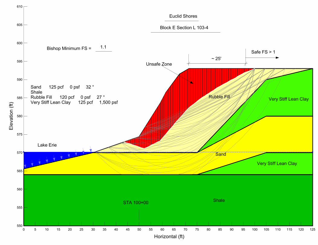
Rubble Fill
Block E Section L 103-4
Bishop Minimum FS =
Very Stiff Lean Clay
Sand
Safe FS > 1
Euclid Shores
Lake Erie
Very Stiff Lean Clay
Sand 125 pcf 0 psf 32 ° Shale Rubble Fill 120 pcf 0 psf 27 ° Very Stiff Lean Clay 125 pcf 1,500 psf
1.1
ShaleSTA 100+00
Unsafe Zone
~ 25'
Horizontal (ft)
0 5 10 15 20 25 30 35 40 45 50 55 60 65 70 75 80 85 90 95 100 105 110 115 120 125
Ele
va
tio
n (
ft)
550
555
560
565
570
575
580
585
590
595
600
605
610

Random Fill
Block E Section L 103-4Bishop Minimum FS =
Very Stiff Lean Clay
Buttress
(With Buttress)
Euclid Shores
Lake Erie
Very Stiff Lean Clay
Sand 125 pcf 0 psf 32 °ShaleRubble Fill 120 pcf 0 psf 27 °Very Stiff Lean Clay 125 pcf 1,500 psfButtress 135 pcf 0 psf 38 °
1.6
ShaleSTA 100+00
Horizontal (ft)0 5 10 15 20 25 30 35 40 45 50 55 60 65 70 75 80 85 90 95 100 105 110 115 120 125
Ele
vatio
n (ft
)
550
555
560
565
570
575
580
585
590
595
600
605
610

Very Stiff Lean Clay
Block F Section L 104-4
Bishop Minimum FS =
Medium Stiff Lean ClayRequires Only Erosion Protection
Euclid Shores
Lake Erie
Medium Stiff Lean Clay 125 pcf 1,000 psf Shale Very Stiff Lean Clay 125 pcf 2,500 psf
3.0
ShaleSTA 100+00
1.2H:1V
Horizontal (ft)
0 5 10 15 20 25 30 35 40 45 50 55 60 65 70 75 80 85 90 95 100 105 110 115 120 125
Elevation (ft)
550
555
560
565
570
575
580
585
590
595
600
605
610
615
620