Embed Size (px)
Citation preview

Geotechnical Engineering Report In-Situ Falling Head Infiltration Testing
Tijeras Arroyo
Geotechnical Exploratory Borings and Laboratory Services
Kirtland AFB NOV Response
W9128F-12-D0003 Task Order 0025
Bernalillo County, New Mexico
December 12, 2015
Terracon Project No. 66155092
Prepared for: CB&I Federal Services
Albuquerque, New Mexico
Prepared by: Terracon Consultants, Inc. Albuquerque, New Mexico
.,,,,,
December 12, 2015
CB&I Federal Services
2440 Louisiana Boulevard NE, Suite 200
Albuquerque, New Mexico 87110
Attn: Mr. Jon Vail
P: (303) 263-0425
Re: Geotechnical Engineering Report
In-Situ Falling Head Infiltration Testing
Tijeras Arroyo
Geotechnical Exploratory Borings and Laboratory Services
Kirtland AFB NOV Response
W9128F-12-D0003 Task Order 0025
Bernalillo County, New Mexico
Terracon Project No. 66155092
Dear Mr. Vail:
Terracon has completed the geotechnical services for the referenced project to be located at
Kirtland Air Force Base in Bernalillo County, New Mexico. Refer to the Site Location Map,
Figure A1, for the project location.
The scope of the services performed for this project included site reconnaissance by a
geotechnical field engineer, a subsurface exploration program, field testing and laboratory
testing. The scope of work was performed in general accordance with the “Statement of Work
for In Situ Falling Head Infiltration Testing, Geotechnical Exploratory Borings and Geotechnical
Laboratory Services” prepared by CB&I Federal Services dated September 2015. The purpose
of these services is to provide geotechnical information to assist CB&I Federal Services in the
design and construction of a well injection field for the disposal of treated water from the
Groundwater Extraction Pilot Implementation Project associated with the Bulk Fuels Facility.
1.0 PROJECT DESCRIPTION
ITEM DESCRIPTION
Project
The project will include the design and construction of a well injection
field for the disposal of treated water from the Groundwater Extraction
Pilot Implementation Project associated with the Bulk Fuels Facility.

Geotechnical Engineering Report In-situ Falling Head Infiltration Testing – Tijeras Arroyo KAFB Albuquerque, New Mexico December 12, 2015 ■ Terracon Project No. 66155092
Responsive ■ Resourceful ■ Reliable 2
ITEM DESCRIPTION
Location Within the channel of the existing Tijeras Arroyo, Kirtland Air Force Base
in Bernalillo County, New Mexico.
Depth of treated water
disposal/injection 0 to 20 feet below existing site grade
2.0 SUBSURFACE EXPLORATION AND TESTING PROCEDURES
A total of 18 test borings were drilled at the site during the period of November 4 through 19,
2015. The borings were drilled to depths of approximately 6-½ to 51-½ feet below the ground
surface at the approximate locations shown on the attached Site Location Map and Exploration
Location Plan. The test borings were located as follows:
Boring Designation Phase/Location Total Depth (feet)
TAB-01 through TAB-06 Exploratory Borings 51-½
TAPTB-01A through TAPTB-06A Shallow Infiltration Test Borings 6-½
TAPTB-01 through TAPTB-06 Deep Infiltration Test Borings 12 to 21-½
The test borings were advanced with a truck-mounted CME-75 drill rig utilizing 8-inch diameter
hollow-stem augers.
CB&I Federal Services located the boring locations in the field. Latitude and longitude were
determined at each boring location using a hand-held GPS unit. The accuracy of boring
locations should only be assumed to the level implied by the methods used.
Lithologic logs of the borings were recorded by the geotechnical field engineer during the drilling
operations. Samples of the subsurface materials were taken at a maximum of 5-foot intervals
by driving split-spoon or ring-barrel samplers.
Penetration resistance measurements were obtained by driving the split-spoon and ring-barrel
samplers into the subsurface materials using a 140-pound hammer falling 30 inches. The
number of blows required to advance the samplers the last 12 inches, or less if hard/very dense
materials were present, of an 18-inch sampling interval was recorded as the standard penetration
resistance value (N). The samples were sealed in the field and then returned to our laboratory for
testing and classification. The effect of the automatic hammer's efficiency has been considered
in the interpretation and analysis of the subsurface information for this report.
Groundwater measurements were made in the test borings during and at the completion of
drilling.

Geotechnical Engineering Report In-situ Falling Head Infiltration Testing – Tijeras Arroyo KAFB Albuquerque, New Mexico December 12, 2015 ■ Terracon Project No. 66155092
Responsive ■ Resourceful ■ Reliable 3
Upon the completion of drilling and sampling operations and to maintain borehole stability in the
infiltration test borings, polyvinyl chloride (PVC) casing was placed to the bottom of the boring
excavations. Per the request of CB&I, 5 feet of slotted PVC casing was placed between the
following intervals:
Boring Designation Screened/Slotted Interval (feet) Total Boring Depth (feet)
TAPTB-01A through TAPTB-06A 0 to 5 5
TAPTB-06 7 to 12 12
TAPTB-01,TAPTB-03 and TAPTB-04 10 to 15 15
TAPTB-02 and TAPTB-05 15 to 20 20
Upon installation of the PVC casing, the infiltration borings were left open (not backfilled) in
preparation for subsequent field falling head infiltration testing. Within 24 hours of the falling head
infiltration testing, the borings were filled with water and allowed to drain for two (2) cycles to
saturate the soils.
After completion of the borings and installation of PVC casing, field falling head infiltration tests
were performed in the infiltration test borings. Per the request of CB&I, testing was performed
over the following depth interval intervals:
Boring Designation Infiltration Test Starting Water Interval Depth (feet)
TAPTB-01A through TAPTB-06A 0 to 5
TAPTB-06 2 to 12
TAPTB-01,TAPTB-03 and TAPTB-04 5 to 15
TAPTB-02 and TAPTB-05 10 to 20
The tests were performed by recording the drop in water level within the casing over time.
Measurements were performed at incremental time intervals until less than 30 percent of the initial
water height remains to provide data points beyond the 37 percent required in the Basic Time Lag
Method (Lambe, T. William and Whitman, Robert V., 1969). Per the Statement of Work (SOW),
the water level readings with depth were graphed on semi-log paper in the field to confirm steady
state conditions and consistent results.
Upon completion of the field infiltration tests, the casing was removed and the borings
backfilled. For the exploratory and deep infiltration test borings, the borings were backfilled with
soil cuttings and a bentonite plug was installed within the upper 10 feet of the boring. Within the
shallow infiltration test borings, the borings were backfilled with bentonite.

Geotechnical Engineering Report In-situ Falling Head Infiltration Testing – Tijeras Arroyo KAFB Albuquerque, New Mexico December 12, 2015 ■ Terracon Project No. 66155092
Responsive ■ Resourceful ■ Reliable 4
3.0 LABORATORY TESTING PROGRAM
Samples retrieved during the field exploration were taken to the laboratory for further
observation by the project geotechnical engineer. As part of the laboratory testing program, the
soil samples were examined in the laboratory by the geotechnical technician and project engineer.
Based on the material’s texture and plasticity, the soil samples were described and classified in
accordance with the attached General Notes and the Unified Soil Classification System (USCS),
respectively. The estimated group symbols for the USCS are shown in the appropriate column on
the boring logs. A brief description of the USCS is included in Appendix A.
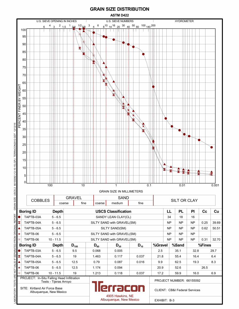
Laboratory tests were conducted on selected soil samples and the test results are presented in
Appendix B. Laboratory tests were performed in general accordance with the applicable ASTM
standard noted below.
Selected soil samples obtained from the site were tested for the following engineering
properties:
Sieve Analysis (ASTM D422) In-situ Water Content (ASTM D2216)
Sieve Analysis (ASTM D6913) Soil Classification (ASTM D2487)
Atterberg Limits (ASTM D4318)
Per the request of CB&I, testing was performed on the following samples:
Boring Designation Sample Depth (feet)
TAB-01 5 and 15
TAB-02 15
TAB-03 10 and 15
TAB-04 10
TAB-05 15
TAB-06 15 and 25
TAPTB-02A 5
TAPTB-03A 5
TAPTB-04A 5
TAPTB-05A 5
TAPTB-06A 5 and 10
The graphical laboratory test results have been included in Appendix B.

Geotechnical Engineering Report In-situ Falling Head Infiltration Testing – Tijeras Arroyo KAFB Albuquerque, New Mexico December 12, 2015 ■ Terracon Project No. 66155092
Responsive ■ Resourceful ■ Reliable 5
4.0 SUBSURFACE CONDITIONS
4.1 Subsurface Conditions
Specific conditions encountered at the boring locations are indicated on the individual boring logs.
Stratification boundaries on the boring logs represent the approximate location of changes in soil
types; in-situ, the transition between materials may be gradual. Details for the borings can be
found on the attached boring logs. Based on the results of the borings, subsurface conditions on
the project site can be generalized as follows:
Description Approximate Depth to
Bottom of Stratum (feet) Material Encountered Consistency/Density
Stratum 1 1 to 3
Well Graded Sand. The
clay, silt and gravel content
varied.
Very Loose to Medium
Dense
Stratum 2 6-½ to 20 Lean Clay. The sand, silt
and gravel content varied Very Soft to Very Stiff
Stratum 3 16 to 30 Silt. The clay, sand and
gravel content varied Soft to Medium Stiff
Stratum 4 25 to 51- ½ Sand. The silt, clay and
gravel content varied Loose to Dense
Stratum 5 28 to 51-½ Lean Clay. The sand, silt
and gravel content varied Soft to Very Stiff
5.0 GROUND WATER INFORMATION
Groundwater was not observed in the test borings at the time of field exploration, nor when
checked upon completion of drilling. However, elevated moisture contents and saturated soils
were encountered in several borings. Due to the interbedded clay layers encountered in the
borings, it is our opinion that “perched” groundwater zones are likely to result during storm,
precipitation, or flow events within the arroyo. These observations represent groundwater
conditions at the time of the field exploration and may not be indicative of other times, or at
other locations. Groundwater conditions can change with varying seasonal and weather
conditions, and other factors.
Fluctuations in groundwater levels can best be determined by implementation of a groundwater
monitoring plan. Such a plan would include installation of groundwater monitoring wells, and
periodic measurement of groundwater levels over a sufficient period of time.

Geotechnical Engineering Report In-situ Falling Head Infiltration Testing – Tijeras Arroyo KAFB Albuquerque, New Mexico December 12, 2015 ■ Terracon Project No. 66155092
Responsive ■ Resourceful ■ Reliable 6
6.0 GEOTECHNICAL ANALYSIS
6.1 Hydraulic Conductivity
The hydraulic conductivity calculations were based upon the Basic Time Lag Method for Falling
Head Method (Lambe, T. William and Whitman, Robert V., 1969). The equation used to calculate
hydraulic conductivity was based upon “Case G Well Point-Filter in Uniform Sand” (from Hvorslev,
1951) using a variable/falling head condition. The Case G profile and hydraulic conductivity
equation are outlined below:
Where:
kh Horizontal Permeability (cm/s)
D Intake Diameter/Diameter of borehole (cm)
d Standpipe Diameter - Solid PVC Casing Diameter above 5 feet/Borehole Diameter below 5 feet (cm)
L Intake Length or Slotted PVC Casing Length (cm)
T Basic Time Lag - Change in time between readings (s)
m Transformation Ratio (unitless)
H1 Depth to water level (cm) at time 1
H2 Depth to water level (cm) at time 2

Geotechnical Engineering Report In-situ Falling Head Infiltration Testing – Tijeras Arroyo KAFB Albuquerque, New Mexico December 12, 2015 ■ Terracon Project No. 66155092
Responsive ■ Resourceful ■ Reliable 7
A summary of the range of hydraulic conductivity values for each Infiltration Boring are
summarized below:
Boring No. Test Interval
(feet)
Hydraulic Conductivity
(cm/sec)*
Hydraulic Conductivity
(gpd/ft2)*
TAPTB-01 10 to 15 1.32x10⁻⁴ to 2.91x10
-6 0.1 to 2.8
TAPTB-01A 0 to 5 1.94x10⁻² to 5.21x10
-4 11 to 412
TAPTB-02 15 to 20 3.85x10⁻⁵ to 4.77x10
-6 0.1 to 0.8
TAPTB-02A 0 to 5 9.46x10⁻³ to 7.66x10
-5 1.6 to 201
TAPTB-03 10 to 15 1.17x10⁻⁴ to 8.19x10
-6 0.2 to 2.5
TAPTB-03A 0 to 5 1.55x10⁻² to 2.35x10
-5 0.5 to 328
TAPTB-04 10 to 15 2.46x10⁻⁴ to 1.74x10
-7 0.1 to 5.2
TAPTB-04A 0 to 5 2.10x10⁻³ to 5.76x10
-5 0.4 to 44
TAPTB-05 15 to 20 4.01x10⁻⁵ to 4.81x10
-6 0.1 to 0.9
TAPTB-05A 0 to 5 1.41x10⁻² to 2.54x10
-5 0.5 to 298
TAPTB-06 7 to 12 2.09x10⁻⁴ to 3.19x10
-6 0.1 to 4.4
TAPTB-06A 0 to 5 1.05x10⁻² to 3.21x10
-5 0.7 to 224
It should be noted that particle size, void ratio, cementation, unit weight, soil lithology, relative
density/consistency, structure, pressure head, and degree of saturation along with other factors
will affect the infiltration rates. Therefore, the actual infiltration rates in the well point injection
areas may vary from the values reported in the borings.
The hydraulic conductivity values at varying depths for each boring are included in Appendix C.
7.0 GENERAL COMMENTS
The analysis presented in this report is based upon the data obtained from the borings
performed at the indicated locations and from other information discussed in this report. This
report does not reflect variations that may occur between borings, across the site, or due to the
modifying effects of construction or weather. The nature and extent of such variations may not
become evident until during or after construction. If variations appear, we should be
immediately notified so that further evaluation and supplemental recommendations can be
provided.

APPENDIX A
FIELD EXPLORATION

TOPOGRAPHIC MAP IMAGE COURTESY OF THE U.S. GEOLOGICAL SURVEY
QUADRANGLES INCLUDE: ALBUQUERQUE
EAST, NM (1/1/1990).
SITE LOCATION MAP
In-Situ Falling Head Infiltration Testing Tijeras Arroyo - KAFB
Albuquerque, NM
4905 Hawkins NE
Albuquerque, NM 87109
66155092
DIAGRAM IS FOR GENERAL LOCATION ONLY, AND IS NOT INTENDED FOR CONSTRUCTION
PURPOSES
Project Manager:
Drawn by:
Checked by: Approved by:
MRA
MEA
MEA
MJD
12/11/2015
Project No.
File Name: Date:
A-1
Exhibit
1”=24,000 SF Scale:
A-2
A-3

EXPLORATION PLAN
4905 Hawkins NE
Albuquerque, NM 87109
66155092 AERIAL PHOTOGRAPHY PROVIDED BY MICROSOFT BING MAPS
In-Situ Falling Head Infiltration Testing Tijeras Arroyo - KAFB
Albuquerque, NM DIAGRAM IS FOR GENERAL LOCATION ONLY, AND IS NOT INTENDED FOR CONSTRUCTION
PURPOSES
Project Manager:
12/11/2015
Drawn by:
Checked by: Approved by:
MRA
MEA
MEA
MJD
Scale:
Project No.
File Name: Date:
AS SHOWN A-2
Exhibit
LEGEND
Deep Infiltration Test Boring
Deep Exploratory Test Boring
Shallow Infiltration Test Boring

LEGEND
Deep Infiltration Test Boring
Deep Exploratory Test Boring
Shallow Infiltration Test Boring
EXPLORATION PLAN
4905 Hawkins NE
Albuquerque, NM 87109
66155092 AERIAL PHOTOGRAPHY PROVIDED BY MICROSOFT BING MAPS
In-Situ Falling Head Infiltration Testing Tijeras Arroyo - KAFB
Albuquerque, NM DIAGRAM IS FOR GENERAL LOCATION ONLY, AND IS NOT INTENDED FOR CONSTRUCTION
PURPOSES
Project Manager:
Drawn by:
Checked by: Approved by:
MRA
MEA
MEA
MJD
?
12/11/2015
Scale:
Project No.
File Name: Date:
AS SHOWN A-3
Exhibit

73
85
27
28
33-20-13
28-22-6
30/50/20
0/0/100
30/50/20
20/40/40
2-3-4N=7
0-0-1N=1
1-1-2N=3
1-2-1N=3
2-2-4N=6
3-4-3N=7
12-20-18N=38
14-6-2N=8
9-20-8N=28
6-2-14N=16
6-5-5N=10
2.0
10.0
20.0
29.0
40.0
42.0
51.5
WELL GRADED SAND (SW), varying amounts of gravel, trace silt,light brown, looseLEAN CLAY WITH SAND (CL), trace gravel, brown, very soft
SILTY CLAY WITH SAND (CL-ML), brown, soft
silty sand lenses
SILTY SAND TO SANDY SILT (SM), brown, loose
WELL GRADED SAND (SW), varying amounts of gravel, light brown,loose to dense, weak cementationtrace cobbles with clay lenses
WELL GRADED TO POORLY GRADED SAND (SW), trace gravel,light brown, medium densewith clay lensesLEAN CLAY (CL), brown to reddish-brown, stiff to very stiff
Boring Terminated at 51.5 Feet
Hammer Type: AutomaticStratification lines are approximate. In-situ, the transition may be gradual.
GR
AP
HIC
LO
G
TH
IS B
OR
ING
LO
G IS
NO
T V
ALI
D IF
SE
PA
RA
TE
D F
RO
M O
RIG
INA
L R
EP
OR
T.
G
EO
SM
AR
T L
OG
-NO
WE
LL 6
615
509
2 (1
2-10
-15)
.GP
J T
ER
RA
CO
N20
15.G
DT
12/
12/1
5
Kirtland Air Force Base Albuquerque, New MexicoSITE:
Page 1 of 1
Advancement Method:Hollow Stem Auger
Abandonment Method:Borings backfilled with soil cuttings upon completion withupper 10' bentonite plug.
4905 Hawkins, NEAlbuquerque, New Mexico
Notes:
Project No.: 66155092
Drill Rig:
Boring Started: 11/4/2015
BORING LOG NO. TAB-01CB&I Federal ServicesCLIENT:
Driller: Juan
Boring Completed: 11/4/2015
Exhibit: A-4
See Exhibit A-3 for description of fieldprocedures.See Appendix B for description of laboratoryprocedures and additional data (if any).
See Appendix C for explanation of symbols andabbreviations.
PROJECT: In-Situ Falling Head Infiltration Tests -Tijeras Arroyo
PE
RC
EN
T F
INE
S
WA
TE
RC
ON
TE
NT
(%
)
ATTERBERGLIMITS
LL-PL-PI
SA
MP
LE T
YP
E
WA
TE
R L
EV
EL
OB
SE
RV
AT
ION
S
DE
PT
H (
Ft.)
5
10
15
20
25
30
35
40
45
50
Vis
ual
San
d G
rain
Siz
e %
(CG
/MG
/FG
)
FIE
LD T
ES
TR
ES
ULT
S
DEPTH
LOCATION See Exhibit A-2
Latitude: 35.028776° Longitude: -106.573084°
No free water observedWATER LEVEL OBSERVATIONS

4813 NP
30/50/20
40/50/10
0/0/100
4-7-8N=15
2-4-3N=7
10-10-5N=15
3-9-7N=16
1-2-3N=5
3-3-3N=6
23-17-30N=47
17-18-18N=36
4-5-4N=9
3-3-3N=6
3-4-4N=8
3.0
15.0
30.0
40.0
43.0
51.5
WELL GRADED SAND (SW), varying amounts of gravel, trace silt,light brown, medium dense
SANDY LEAN CLAY TO LEAN CLAY (CL), brown, medium stiff to verystiff
well-graded sand lenses
SILTY SAND (SM), trace clay and gravel, brown, loose to mediumdense
WELL GRADED SAND, varying amounts of gravel, light brown, dense,weak cementation
SILTY SAND TO SANDY SILT (SM), light brown, loose
LEAN CLAY (CL), brown, medium stiff to stiff
with silty clay lenses
Boring Terminated at 51.5 Feet
Hammer Type: AutomaticStratification lines are approximate. In-situ, the transition may be gradual.
GR
AP
HIC
LO
G
TH
IS B
OR
ING
LO
G IS
NO
T V
ALI
D IF
SE
PA
RA
TE
D F
RO
M O
RIG
INA
L R
EP
OR
T.
G
EO
SM
AR
T L
OG
-NO
WE
LL 6
615
509
2 (1
2-10
-15)
.GP
J T
ER
RA
CO
N20
15.G
DT
12/
12/1
5
Kirtland Air Force Base Albuquerque, New MexicoSITE:
Page 1 of 1
Advancement Method:Hollow Stem Auger
Abandonment Method:Borings backfilled with soil cuttings upon completion withupper 10' bentonite plug.
4905 Hawkins, NEAlbuquerque, New Mexico
Notes:
Project No.: 66155092
Drill Rig:
Boring Started: 11/4/2015
BORING LOG NO. TAB-02CB&I Federal ServicesCLIENT:
Driller: Juan
Boring Completed: 11/4/2015
Exhibit: A-5
See Exhibit A-3 for description of fieldprocedures.See Appendix B for description of laboratoryprocedures and additional data (if any).
See Appendix C for explanation of symbols andabbreviations.
PROJECT: In-Situ Falling Head Infiltration Tests -Tijeras Arroyo
PE
RC
EN
T F
INE
S
WA
TE
RC
ON
TE
NT
(%
)
ATTERBERGLIMITS
LL-PL-PI
SA
MP
LE T
YP
E
WA
TE
R L
EV
EL
OB
SE
RV
AT
ION
S
DE
PT
H (
Ft.)
5
10
15
20
25
30
35
40
45
50
Vis
ual
San
d G
rain
Siz
e %
(CG
/MG
/FG
)
FIE
LD T
ES
TR
ES
ULT
S
DEPTH
LOCATION See Exhibit A-2
Latitude: 35.028564° Longitude: -106.57182°
No free water observedWATER LEVEL OBSERVATIONS

62
57
17
16
NP
NP
4-7-7N=14
1-1-1N=2
1-1-2N=3
1-1-2N=3
1-2-1N=3
16-5-5N=10
2-1-1N=2
2-3-3N=6
3-3-4N=7
5-3-4N=7
9-6-11N=17
3.0
8.0
16.0
51.5
WELL GRADED SAND (SW), varying amounts of gravel, light brown,medium dense
LEAN CLAY (CL), brown, soft
SANDY SILT (ML), brown, soft
lean clay lenses
LEAN CLAY (CL), brown, soft to very stiff
sandy silt lenses
Boring Terminated at 51.5 Feet
Hammer Type: AutomaticStratification lines are approximate. In-situ, the transition may be gradual.
GR
AP
HIC
LO
G
TH
IS B
OR
ING
LO
G IS
NO
T V
ALI
D IF
SE
PA
RA
TE
D F
RO
M O
RIG
INA
L R
EP
OR
T.
G
EO
SM
AR
T L
OG
-NO
WE
LL 6
615
509
2 (1
2-10
-15)
.GP
J T
ER
RA
CO
N20
15.G
DT
12/
12/1
5
Kirtland Air Force Base Albuquerque, New MexicoSITE:
Page 1 of 1
Advancement Method:Hollow Stem Auger
Abandonment Method:Borings backfilled with soil cuttings upon completion withupper 10' bentonite plug.
4905 Hawkins, NEAlbuquerque, New Mexico
Notes:
Project No.: 66155092
Drill Rig:
Boring Started: 11/4/2015
BORING LOG NO. TAB-03CB&I Federal ServicesCLIENT:
Driller: Juan
Boring Completed: 11/4/2015
Exhibit: A-6
See Exhibit A-3 for description of fieldprocedures.See Appendix B for description of laboratoryprocedures and additional data (if any).
See Appendix C for explanation of symbols andabbreviations.
PROJECT: In-Situ Falling Head Infiltration Tests -Tijeras Arroyo
PE
RC
EN
T F
INE
S
WA
TE
RC
ON
TE
NT
(%
)
ATTERBERGLIMITS
LL-PL-PI
SA
MP
LE T
YP
E
WA
TE
R L
EV
EL
OB
SE
RV
AT
ION
S
DE
PT
H (
Ft.)
5
10
15
20
25
30
35
40
45
50
Vis
ual
San
d G
rain
Siz
e %
(CG
/MG
/FG
)
FIE
LD T
ES
TR
ES
ULT
S
DEPTH
LOCATION See Exhibit A-2
Latitude: 35.028506° Longitude: -106.570627°
No free water observedWATER LEVEL OBSERVATIONS
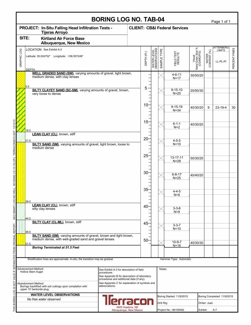
309 23-19-4
30/50/20
20/50/30
40/30/20
40/30/20
50/30/20
40/40/20
40/30/30
4-6-11N=17
9-15-10N=25
9-15-19N=34
6-1-1N=2
4-5-5N=10
13-17-11N=28
6-8-17N=25
4-4-5N=9
3-3-6N=9
3-3-7N=10
10-9-7N=16
5.0
18.0
21.0
39.0
44.0
48.0
51.5
WELL GRADED SAND (SW), varying amounts of gravel, light brown,medium dense, with clay lenses
SILTY CLAYEY SAND (SC-SM), varying amounts of gravel, brown,very loose to dense
LEAN CLAY (CL), brown, stiff
SILTY SAND (SM), varying amounts of gravel, light brown, loose tomedium dense
LEAN CLAY (CL), brown, stiffsilty clay lenses
SILTY CLAY (CL-ML), brown, stiff
SILTY SAND (SM), varying amounts of gravel, brown and light brown,medium dense, with well-graded sand and gravel lenses
Boring Terminated at 51.5 Feet
Hammer Type: AutomaticStratification lines are approximate. In-situ, the transition may be gradual.
GR
AP
HIC
LO
G
TH
IS B
OR
ING
LO
G IS
NO
T V
ALI
D IF
SE
PA
RA
TE
D F
RO
M O
RIG
INA
L R
EP
OR
T.
G
EO
SM
AR
T L
OG
-NO
WE
LL 6
615
509
2 (1
2-10
-15)
.GP
J T
ER
RA
CO
N20
15.G
DT
12/
12/1
5
Kirtland Air Force Base Albuquerque, New MexicoSITE:
Page 1 of 1
Advancement Method:Hollow Stem Auger
Abandonment Method:Borings backfilled with soil cuttings upon completion withupper 10' bentonite plug.
4905 Hawkins, NEAlbuquerque, New Mexico
Notes:
Project No.: 66155092
Drill Rig:
Boring Started: 11/9/2015
BORING LOG NO. TAB-04CB&I Federal ServicesCLIENT:
Driller: Juan
Boring Completed: 11/9/2015
Exhibit: A-7
See Exhibit A-3 for description of fieldprocedures.See Appendix B for description of laboratoryprocedures and additional data (if any).
See Appendix C for explanation of symbols andabbreviations.
PROJECT: In-Situ Falling Head Infiltration Tests -Tijeras Arroyo
PE
RC
EN
T F
INE
S
WA
TE
RC
ON
TE
NT
(%
)
ATTERBERGLIMITS
LL-PL-PI
SA
MP
LE T
YP
E
WA
TE
R L
EV
EL
OB
SE
RV
AT
ION
S
DE
PT
H (
Ft.)
5
10
15
20
25
30
35
40
45
50
Vis
ual
San
d G
rain
Siz
e %
(CG
/MG
/FG
)
FIE
LD T
ES
TR
ES
ULT
S
DEPTH
LOCATION See Exhibit A-2
Latitude: 35.024752° Longitude: -106.557249°
No free water observedWATER LEVEL OBSERVATIONS

258 19-16-3
50/40/10
50/30/20
30/30/40
30/40/30
40/50/10
5-6-10N=16
28-16-13N=29
18-16-19N=35
7-11-7N=18
4-2-2N=4
2-2-2N=4
6-3-2N=5
3-4-5N=9
4-4-7N=11
5-4-5N=9
11-16-18N=34
10.0
20.0
28.0
32.0
50.0
51.5
WELL GRADED SAND (SW), varying amounts of gravel and cobbles,light brown to brown, medium densesilty sand lenses
lean clay lenses
increase in amount of gravel
SILTY SAND (SM), varying amounts of gravel, brown, medium denseto denselean clay lenses
medium dense
SILTY CLAY (CL-ML), brown, soft to medium stiff
silty sand lenses
LEAN CLAY (CL), brown, medium stiff
SILTY CLAY (CL-ML), brown, stiff
silty sand lenses
WELL GRADED SAND WITH SILT (SW-SM), light brown, dense
Boring Terminated at 51.5 Feet
Hammer Type: AutomaticStratification lines are approximate. In-situ, the transition may be gradual.
GR
AP
HIC
LO
G
TH
IS B
OR
ING
LO
G IS
NO
T V
ALI
D IF
SE
PA
RA
TE
D F
RO
M O
RIG
INA
L R
EP
OR
T.
G
EO
SM
AR
T L
OG
-NO
WE
LL 6
615
509
2 (1
2-10
-15)
.GP
J T
ER
RA
CO
N20
15.G
DT
12/
12/1
5
Kirtland Air Force Base Albuquerque, New MexicoSITE:
Page 1 of 1
Advancement Method:Hollow Stem Auger
Abandonment Method:Borings backfilled with soil cuttings upon completion withupper 10' bentonite plug.
4905 Hawkins, NEAlbuquerque, New Mexico
Notes:
Project No.: 66155092
Drill Rig:
Boring Started: 11/9/2015
BORING LOG NO. TAB-05CB&I Federal ServicesCLIENT:
Driller: Juan
Boring Completed: 11/9/2015
Exhibit: A-8
See Exhibit A-3 for description of fieldprocedures.See Appendix B for description of laboratoryprocedures and additional data (if any).
See Appendix C for explanation of symbols andabbreviations.
PROJECT: In-Situ Falling Head Infiltration Tests -Tijeras Arroyo
PE
RC
EN
T F
INE
S
WA
TE
RC
ON
TE
NT
(%
)
ATTERBERGLIMITS
LL-PL-PI
SA
MP
LE T
YP
E
WA
TE
R L
EV
EL
OB
SE
RV
AT
ION
S
DE
PT
H (
Ft.)
5
10
15
20
25
30
35
40
45
50
Vis
ual
San
d G
rain
Siz
e %
(CG
/MG
/FG
)
FIE
LD T
ES
TR
ES
ULT
S
DEPTH
LOCATION See Exhibit A-2
Latitude: 35.024309° Longitude: -106.556704°
No free water observedWATER LEVEL OBSERVATIONS

33
55
8
11
NP
NP
50/40/10
30/35/35
60/30/10
50/30/20
40/40/20
0/10/90
0/10/90
50/40/10
4-5-6N=11
9-14-18N=32
14-24-15N=39
11-20-19N=39
23-23-12N=35
3-3-3N=6
3-4-5N=9
4-7-6N=13
5-6-4N=10
4-6-6N=12
8-12-9N=21
2.0
25.0
30.0
35.0
40.0
50.0
51.5
WELL GRADED SAND (SW), varying amounts of gravel and cobbles,light brown, medium denseSILTY SAND (SM), varying amounts of gravel, brown, dense
2 foot thick gravel layerlean clay lenses
2 foot thick gravel layer
sandy silt lenses
SANDY SILT (ML), light brown to brown, medium stiff
SILTY CLAY (CL-ML), brown, stiff
sandy silt lenses
SILTY SAND (SM), brown to light brown, medium dense
lean clay lenses
SILTY CLAY (CL-ML), brown to dark brown, stiff
silty sand lenses
WELL GRADED SAND WITH GRAVEL (SW), light brown, mediumdenseBoring Terminated at 51.5 Feet
Hammer Type: AutomaticStratification lines are approximate. In-situ, the transition may be gradual.
GR
AP
HIC
LO
G
TH
IS B
OR
ING
LO
G IS
NO
T V
ALI
D IF
SE
PA
RA
TE
D F
RO
M O
RIG
INA
L R
EP
OR
T.
G
EO
SM
AR
T L
OG
-NO
WE
LL 6
615
509
2 (1
2-10
-15)
.GP
J T
ER
RA
CO
N20
15.G
DT
12/
12/1
5
Kirtland Air Force Base Albuquerque, New MexicoSITE:
Page 1 of 1
Advancement Method:Hollow Stem Auger
Abandonment Method:Borings backfilled with soil cuttings upon completion withupper 10' bentonite plug.
4905 Hawkins, NEAlbuquerque, New Mexico
Notes:
Project No.: 66155092
Drill Rig:
Boring Started: 11/10/2015
BORING LOG NO. TAB-06CB&I Federal ServicesCLIENT:
Driller: Juan
Boring Completed: 11/10/2015
Exhibit: A-9
See Exhibit A-3 for description of fieldprocedures.See Appendix B for description of laboratoryprocedures and additional data (if any).
See Appendix C for explanation of symbols andabbreviations.
PROJECT: In-Situ Falling Head Infiltration Tests -Tijeras Arroyo
PE
RC
EN
T F
INE
S
WA
TE
RC
ON
TE
NT
(%
)
ATTERBERGLIMITS
LL-PL-PI
SA
MP
LE T
YP
E
WA
TE
R L
EV
EL
OB
SE
RV
AT
ION
S
DE
PT
H (
Ft.)
5
10
15
20
25
30
35
40
45
50
Vis
ual
San
d G
rain
Siz
e %
(CG
/MG
/FG
)
FIE
LD T
ES
TR
ES
ULT
S
DEPTH
LOCATION See Exhibit A-2
Latitude: 35.024194° Longitude: -106.555647°
No free water observedWATER LEVEL OBSERVATIONS
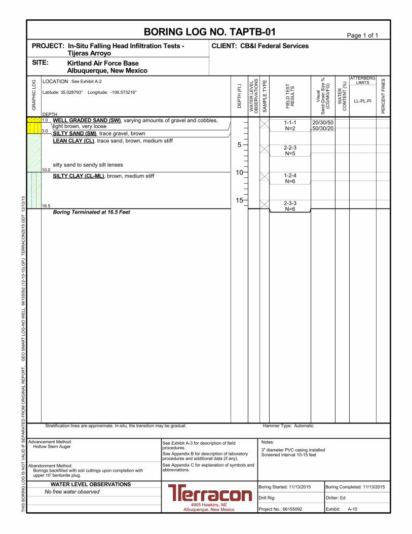
3" diameter PVC casing installedScreened interval 10-15 feet
20/30/5050/30/20
1-1-1N=2
2-2-3N=5
1-2-4N=6
2-3-3N=6
1.0
3.0
10.0
16.5
WELL GRADED SAND (SW), varying amounts of gravel and cobbles,light brown, very looseSILTY SAND (SM), trace gravel, brownLEAN CLAY (CL), trace sand, brown, medium stiff
silty sand to sandy silt lenses
SILTY CLAY (CL-ML), brown, medium stiff
Boring Terminated at 16.5 Feet
Hammer Type: AutomaticStratification lines are approximate. In-situ, the transition may be gradual.
GR
AP
HIC
LO
G
TH
IS B
OR
ING
LO
G IS
NO
T V
ALI
D IF
SE
PA
RA
TE
D F
RO
M O
RIG
INA
L R
EP
OR
T.
G
EO
SM
AR
T L
OG
-NO
WE
LL 6
615
509
2 (1
2-10
-15)
.GP
J T
ER
RA
CO
N20
15.G
DT
12/
12/1
5
Kirtland Air Force Base Albuquerque, New MexicoSITE:
Page 1 of 1
Advancement Method:Hollow Stem Auger
Abandonment Method:Borings backfilled with soil cuttings upon completion withupper 10' bentonite plug.
4905 Hawkins, NEAlbuquerque, New Mexico
Notes:
Project No.: 66155092
Drill Rig:
Boring Started: 11/13/2015
BORING LOG NO. TAPTB-01CB&I Federal ServicesCLIENT:
Driller: Ed
Boring Completed: 11/13/2015
Exhibit: A-10
See Exhibit A-3 for description of fieldprocedures.See Appendix B for description of laboratoryprocedures and additional data (if any).
See Appendix C for explanation of symbols andabbreviations.
PROJECT: In-Situ Falling Head Infiltration Tests -Tijeras Arroyo
PE
RC
EN
T F
INE
S
WA
TE
RC
ON
TE
NT
(%
)
ATTERBERGLIMITS
LL-PL-PI
SA
MP
LE T
YP
E
WA
TE
R L
EV
EL
OB
SE
RV
AT
ION
S
DE
PT
H (
Ft.)
5
10
15
Vis
ual
San
d G
rain
Siz
e %
(CG
/MG
/FG
)
FIE
LD T
ES
TR
ES
ULT
S
DEPTH
LOCATION See Exhibit A-2
Latitude: 35.028793° Longitude: -106.573216°
No free water observedWATER LEVEL OBSERVATIONS
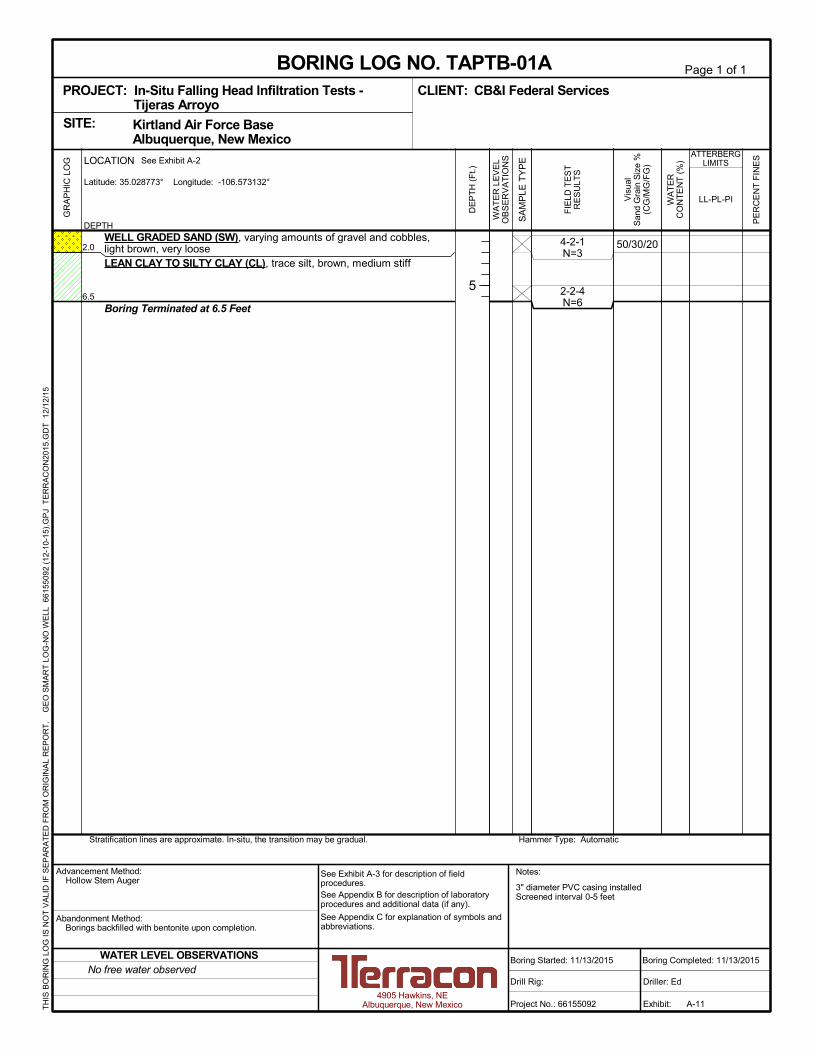
3" diameter PVC casing installedScreened interval 0-5 feet
50/30/204-2-1N=3
2-2-4N=6
2.0
6.5
WELL GRADED SAND (SW), varying amounts of gravel and cobbles,light brown, very looseLEAN CLAY TO SILTY CLAY (CL), trace silt, brown, medium stiff
Boring Terminated at 6.5 Feet
Hammer Type: AutomaticStratification lines are approximate. In-situ, the transition may be gradual.
GR
AP
HIC
LO
G
TH
IS B
OR
ING
LO
G IS
NO
T V
ALI
D IF
SE
PA
RA
TE
D F
RO
M O
RIG
INA
L R
EP
OR
T.
G
EO
SM
AR
T L
OG
-NO
WE
LL 6
615
509
2 (1
2-10
-15)
.GP
J T
ER
RA
CO
N20
15.G
DT
12/
12/1
5
Kirtland Air Force Base Albuquerque, New MexicoSITE:
Page 1 of 1
Advancement Method:Hollow Stem Auger
Abandonment Method:Borings backfilled with bentonite upon completion.
4905 Hawkins, NEAlbuquerque, New Mexico
Notes:
Project No.: 66155092
Drill Rig:
Boring Started: 11/13/2015
BORING LOG NO. TAPTB-01ACB&I Federal ServicesCLIENT:
Driller: Ed
Boring Completed: 11/13/2015
Exhibit: A-11
See Exhibit A-3 for description of fieldprocedures.See Appendix B for description of laboratoryprocedures and additional data (if any).
See Appendix C for explanation of symbols andabbreviations.
PROJECT: In-Situ Falling Head Infiltration Tests -Tijeras Arroyo
PE
RC
EN
T F
INE
S
WA
TE
RC
ON
TE
NT
(%
)
ATTERBERGLIMITS
LL-PL-PI
SA
MP
LE T
YP
E
WA
TE
R L
EV
EL
OB
SE
RV
AT
ION
S
DE
PT
H (
Ft.)
5
Vis
ual
San
d G
rain
Siz
e %
(CG
/MG
/FG
)
FIE
LD T
ES
TR
ES
ULT
S
DEPTH
LOCATION See Exhibit A-2
Latitude: 35.028773° Longitude: -106.573132°
No free water observedWATER LEVEL OBSERVATIONS

3" diameter PVC casing installedScreened interval 15-20 feet
50/30/204-7-7N=14
2-2-4N=6
4-3-3N=6
3-4-3N=7
3-3-4N=7
3.0
12.0
21.5
WELL GRADED SAND (SW), varying amounts of gravel and cobbles,light brown, medium dense
LEAN CLAY (CL), brown, medium stiff, with silty sand to sandy siltlenses
SANDY SILT (ML), brown to light brown, medium stiff, with silty claylenses
Boring Terminated at 21.5 Feet
Hammer Type: AutomaticStratification lines are approximate. In-situ, the transition may be gradual.
GR
AP
HIC
LO
G
TH
IS B
OR
ING
LO
G IS
NO
T V
ALI
D IF
SE
PA
RA
TE
D F
RO
M O
RIG
INA
L R
EP
OR
T.
G
EO
SM
AR
T L
OG
-NO
WE
LL 6
615
509
2 (1
2-10
-15)
.GP
J T
ER
RA
CO
N20
15.G
DT
12/
12/1
5
Kirtland Air Force Base Albuquerque, New MexicoSITE:
Page 1 of 1
Advancement Method:Hollow Stem Auger
Abandonment Method:Borings backfilled with soil cuttings upon completion withupper 10' bentonite plug.
4905 Hawkins, NEAlbuquerque, New Mexico
Notes:
Project No.: 66155092
Drill Rig:
Boring Started: 11/13/2015
BORING LOG NO. TAPTB-02CB&I Federal ServicesCLIENT:
Driller: Ed
Boring Completed: 11/13/2015
Exhibit: A-12
See Exhibit A-3 for description of fieldprocedures.See Appendix B for description of laboratoryprocedures and additional data (if any).
See Appendix C for explanation of symbols andabbreviations.
PROJECT: In-Situ Falling Head Infiltration Tests -Tijeras Arroyo
PE
RC
EN
T F
INE
S
WA
TE
RC
ON
TE
NT
(%
)
ATTERBERGLIMITS
LL-PL-PI
SA
MP
LE T
YP
E
WA
TE
R L
EV
EL
OB
SE
RV
AT
ION
S
DE
PT
H (
Ft.)
5
10
15
20
Vis
ual
San
d G
rain
Siz
e %
(CG
/MG
/FG
)
FIE
LD T
ES
TR
ES
ULT
S
DEPTH
LOCATION See Exhibit A-2
Latitude: 35.028629° Longitude: -106.571949°
No free water observedWATER LEVEL OBSERVATIONS
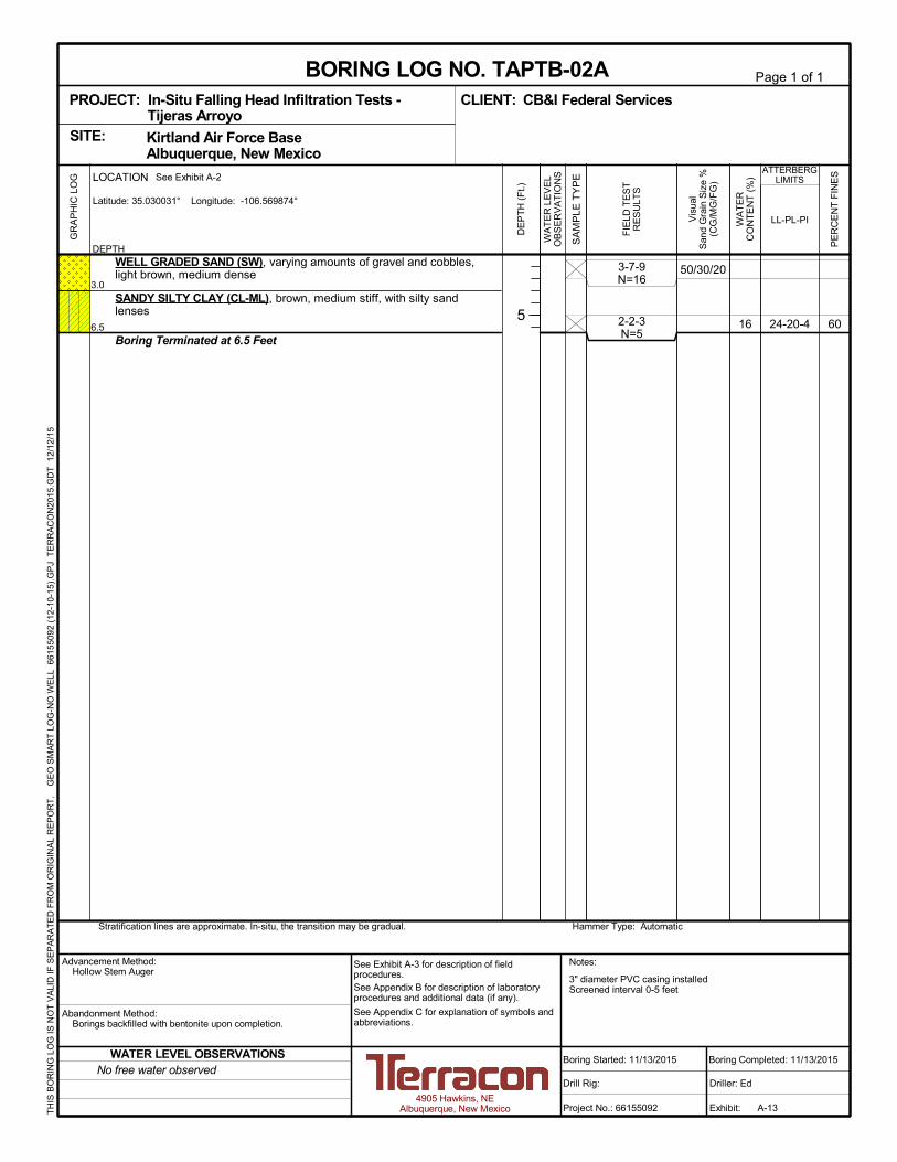
3" diameter PVC casing installedScreened interval 0-5 feet
6016 24-20-4
50/30/203-7-9N=16
2-2-3N=5
3.0
6.5
WELL GRADED SAND (SW), varying amounts of gravel and cobbles,light brown, medium dense
SANDY SILTY CLAY (CL-ML), brown, medium stiff, with silty sandlenses
Boring Terminated at 6.5 Feet
Hammer Type: AutomaticStratification lines are approximate. In-situ, the transition may be gradual.
GR
AP
HIC
LO
G
TH
IS B
OR
ING
LO
G IS
NO
T V
ALI
D IF
SE
PA
RA
TE
D F
RO
M O
RIG
INA
L R
EP
OR
T.
G
EO
SM
AR
T L
OG
-NO
WE
LL 6
615
509
2 (1
2-10
-15)
.GP
J T
ER
RA
CO
N20
15.G
DT
12/
12/1
5
Kirtland Air Force Base Albuquerque, New MexicoSITE:
Page 1 of 1
Advancement Method:Hollow Stem Auger
Abandonment Method:Borings backfilled with bentonite upon completion.
4905 Hawkins, NEAlbuquerque, New Mexico
Notes:
Project No.: 66155092
Drill Rig:
Boring Started: 11/13/2015
BORING LOG NO. TAPTB-02ACB&I Federal ServicesCLIENT:
Driller: Ed
Boring Completed: 11/13/2015
Exhibit: A-13
See Exhibit A-3 for description of fieldprocedures.See Appendix B for description of laboratoryprocedures and additional data (if any).
See Appendix C for explanation of symbols andabbreviations.
PROJECT: In-Situ Falling Head Infiltration Tests -Tijeras Arroyo
PE
RC
EN
T F
INE
S
WA
TE
RC
ON
TE
NT
(%
)
ATTERBERGLIMITS
LL-PL-PI
SA
MP
LE T
YP
E
WA
TE
R L
EV
EL
OB
SE
RV
AT
ION
S
DE
PT
H (
Ft.)
5
Vis
ual
San
d G
rain
Siz
e %
(CG
/MG
/FG
)
FIE
LD T
ES
TR
ES
ULT
S
DEPTH
LOCATION See Exhibit A-2
Latitude: 35.030031° Longitude: -106.569874°
No free water observedWATER LEVEL OBSERVATIONS

3" diameter PVC casing installedScreened interval 10-15 feet
50/30/203-4-3N=7
1-1-3N=4
2-2-2N=4
2-2-2N=4
3.0
16.5
WELL GRADED SAND (SW), varying amounts of gravel and cobbles,light brown, loose
SANDY SILT (ML), brown to light brown, soft to medium stiff, with leanclay lenses
Boring Terminated at 16.5 Feet
Hammer Type: AutomaticStratification lines are approximate. In-situ, the transition may be gradual.
GR
AP
HIC
LO
G
TH
IS B
OR
ING
LO
G IS
NO
T V
ALI
D IF
SE
PA
RA
TE
D F
RO
M O
RIG
INA
L R
EP
OR
T.
G
EO
SM
AR
T L
OG
-NO
WE
LL 6
615
509
2 (1
2-10
-15)
.GP
J T
ER
RA
CO
N20
15.G
DT
12/
12/1
5
Kirtland Air Force Base Albuquerque, New MexicoSITE:
Page 1 of 1
Advancement Method:Hollow Stem Auger
Abandonment Method:Borings backfilled with soil cuttings upon completion withupper 10' bentonite plug.
4905 Hawkins, NEAlbuquerque, New Mexico
Notes:
Project No.: 66155092
Drill Rig:
Boring Started: 11/13/2015
BORING LOG NO. TAPTB-03CB&I Federal ServicesCLIENT:
Driller: Ed
Boring Completed: 11/13/2015
Exhibit: A-14
See Exhibit A-3 for description of fieldprocedures.See Appendix B for description of laboratoryprocedures and additional data (if any).
See Appendix C for explanation of symbols andabbreviations.
PROJECT: In-Situ Falling Head Infiltration Tests -Tijeras Arroyo
PE
RC
EN
T F
INE
S
WA
TE
RC
ON
TE
NT
(%
)
ATTERBERGLIMITS
LL-PL-PI
SA
MP
LE T
YP
E
WA
TE
R L
EV
EL
OB
SE
RV
AT
ION
S
DE
PT
H (
Ft.)
5
10
15
Vis
ual
San
d G
rain
Siz
e %
(CG
/MG
/FG
)
FIE
LD T
ES
TR
ES
ULT
S
DEPTH
LOCATION See Exhibit A-2
Latitude: 35.028528° Longitude: -106.57073°
No free water observedWATER LEVEL OBSERVATIONS

3" diameter PVC casing installedScreened interval 0-5 feet
6225 34-18-16
50/30/204-3-5N=8
2-2-4N=6
2.0
6.5
WELL GRADED SAND (SW), varying amounts of gravel and cobbles,light brown, looseSANDY LEAN CLAY (CL), brown, medium stiff
Boring Terminated at 6.5 Feet
Hammer Type: AutomaticStratification lines are approximate. In-situ, the transition may be gradual.
GR
AP
HIC
LO
G
TH
IS B
OR
ING
LO
G IS
NO
T V
ALI
D IF
SE
PA
RA
TE
D F
RO
M O
RIG
INA
L R
EP
OR
T.
G
EO
SM
AR
T L
OG
-NO
WE
LL 6
615
509
2 (1
2-10
-15)
.GP
J T
ER
RA
CO
N20
15.G
DT
12/
12/1
5
Kirtland Air Force Base Albuquerque, New MexicoSITE:
Page 1 of 1
Advancement Method:Hollow Stem Auger
Abandonment Method:Borings backfilled with bentonite upon completion.
4905 Hawkins, NEAlbuquerque, New Mexico
Notes:
Project No.: 66155092
Drill Rig:
Boring Started: 11/13/2015
BORING LOG NO. TAPTB-03ACB&I Federal ServicesCLIENT:
Driller: Ed
Boring Completed: 11/13/2015
Exhibit: A-15
See Exhibit A-3 for description of fieldprocedures.See Appendix B for description of laboratoryprocedures and additional data (if any).
See Appendix C for explanation of symbols andabbreviations.
PROJECT: In-Situ Falling Head Infiltration Tests -Tijeras Arroyo
PE
RC
EN
T F
INE
S
WA
TE
RC
ON
TE
NT
(%
)
ATTERBERGLIMITS
LL-PL-PI
SA
MP
LE T
YP
E
WA
TE
R L
EV
EL
OB
SE
RV
AT
ION
S
DE
PT
H (
Ft.)
5
Vis
ual
San
d G
rain
Siz
e %
(CG
/MG
/FG
)
FIE
LD T
ES
TR
ES
ULT
S
DEPTH
LOCATION See Exhibit A-2
Latitude: 35.028481° Longitude: -106.570581°
No free water observedWATER LEVEL OBSERVATIONS

3" diameter PVC casing installedScreened interval 10-15 feet
40/30/2030/50/20
30/40/30
50/40/10
30/40/30
4-10-10N=20
7-12-14N=26
19-16-26N=42
8-10-6N=16
1.0
8.0
16.5
WELL GRADED SAND (SW), varying amounts of gravel and cobbles,light brown, medium denseSILTY SAND (SM), varying amounts of gravel, brown, medium dense
SILTY CLAYEY SAND WITH GRAVEL (SC-SM), brown, mediumdense to dense, with lean clay lenses
Boring Terminated at 16.5 Feet
Hammer Type: AutomaticStratification lines are approximate. In-situ, the transition may be gradual.
GR
AP
HIC
LO
G
TH
IS B
OR
ING
LO
G IS
NO
T V
ALI
D IF
SE
PA
RA
TE
D F
RO
M O
RIG
INA
L R
EP
OR
T.
G
EO
SM
AR
T L
OG
-NO
WE
LL 6
615
509
2 (1
2-10
-15)
.GP
J T
ER
RA
CO
N20
15.G
DT
12/
12/1
5
Kirtland Air Force Base Albuquerque, New MexicoSITE:
Page 1 of 1
Advancement Method:Hollow Stem Auger
Abandonment Method:Borings backfilled with soil cuttings upon completion withupper 10' bentonite plug.
4905 Hawkins, NEAlbuquerque, New Mexico
Notes:
Project No.: 66155092
Drill Rig:
Boring Started: 11/19/2015
BORING LOG NO. TAPTB-04CB&I Federal ServicesCLIENT:
Driller: Ed
Boring Completed: 11/19/2015
Exhibit: A-16
See Exhibit A-3 for description of fieldprocedures.See Appendix B for description of laboratoryprocedures and additional data (if any).
See Appendix C for explanation of symbols andabbreviations.
PROJECT: In-Situ Falling Head Infiltration Tests -Tijeras Arroyo
PE
RC
EN
T F
INE
S
WA
TE
RC
ON
TE
NT
(%
)
ATTERBERGLIMITS
LL-PL-PI
SA
MP
LE T
YP
E
WA
TE
R L
EV
EL
OB
SE
RV
AT
ION
S
DE
PT
H (
Ft.)
5
10
15
Vis
ual
San
d G
rain
Siz
e %
(CG
/MG
/FG
)
FIE
LD T
ES
TR
ES
ULT
S
DEPTH
LOCATION See Exhibit A-2
Latitude: 35.024844° Longitude: -106.557261°
No free water observedWATER LEVEL OBSERVATIONS

3" diameter PVC casing installedScreened interval 0-5 feet
238 NP
40/30/2050/40/10
30/40/30
5-9-9N=18
7-9-9N=18
1.5
6.5
WELL GRADED SAND (SW), varying amounts of gravel and cobbles,light brown, medium denseSILTY SAND WITH GRAVEL (SM), brown, medium dense, with leanclay lenses
Boring Terminated at 6.5 Feet
Hammer Type: AutomaticStratification lines are approximate. In-situ, the transition may be gradual.
GR
AP
HIC
LO
G
TH
IS B
OR
ING
LO
G IS
NO
T V
ALI
D IF
SE
PA
RA
TE
D F
RO
M O
RIG
INA
L R
EP
OR
T.
G
EO
SM
AR
T L
OG
-NO
WE
LL 6
615
509
2 (1
2-10
-15)
.GP
J T
ER
RA
CO
N20
15.G
DT
12/
12/1
5
Kirtland Air Force Base Albuquerque, New MexicoSITE:
Page 1 of 1
Advancement Method:Hollow Stem Auger
Abandonment Method:Borings backfilled with bentonite upon completion.
4905 Hawkins, NEAlbuquerque, New Mexico
Notes:
Project No.: 66155092
Drill Rig:
Boring Started: 11/19/2015
BORING LOG NO. TAPTB-04ACB&I Federal ServicesCLIENT:
Driller: Ed
Boring Completed: 11/19/2015
Exhibit: A-17
See Exhibit A-3 for description of fieldprocedures.See Appendix B for description of laboratoryprocedures and additional data (if any).
See Appendix C for explanation of symbols andabbreviations.
PROJECT: In-Situ Falling Head Infiltration Tests -Tijeras Arroyo
PE
RC
EN
T F
INE
S
WA
TE
RC
ON
TE
NT
(%
)
ATTERBERGLIMITS
LL-PL-PI
SA
MP
LE T
YP
E
WA
TE
R L
EV
EL
OB
SE
RV
AT
ION
S
DE
PT
H (
Ft.)
5
Vis
ual
San
d G
rain
Siz
e %
(CG
/MG
/FG
)
FIE
LD T
ES
TR
ES
ULT
S
DEPTH
LOCATION See Exhibit A-2
Latitude: 35.024816° Longitude: -106.557234°
No free water observedWATER LEVEL OBSERVATIONS
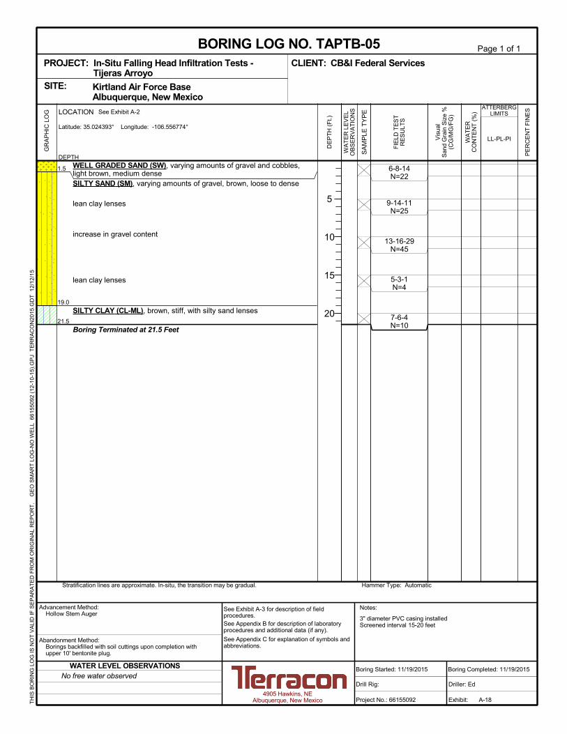
3" diameter PVC casing installedScreened interval 15-20 feet
6-8-14N=22
9-14-11N=25
13-16-29N=45
5-3-1N=4
7-6-4N=10
1.5
19.0
21.5
WELL GRADED SAND (SW), varying amounts of gravel and cobbles,light brown, medium denseSILTY SAND (SM), varying amounts of gravel, brown, loose to dense
lean clay lenses
increase in gravel content
lean clay lenses
SILTY CLAY (CL-ML), brown, stiff, with silty sand lenses
Boring Terminated at 21.5 Feet
Hammer Type: AutomaticStratification lines are approximate. In-situ, the transition may be gradual.
GR
AP
HIC
LO
G
TH
IS B
OR
ING
LO
G IS
NO
T V
ALI
D IF
SE
PA
RA
TE
D F
RO
M O
RIG
INA
L R
EP
OR
T.
G
EO
SM
AR
T L
OG
-NO
WE
LL 6
615
509
2 (1
2-10
-15)
.GP
J T
ER
RA
CO
N20
15.G
DT
12/
12/1
5
Kirtland Air Force Base Albuquerque, New MexicoSITE:
Page 1 of 1
Advancement Method:Hollow Stem Auger
Abandonment Method:Borings backfilled with soil cuttings upon completion withupper 10' bentonite plug.
4905 Hawkins, NEAlbuquerque, New Mexico
Notes:
Project No.: 66155092
Drill Rig:
Boring Started: 11/19/2015
BORING LOG NO. TAPTB-05CB&I Federal ServicesCLIENT:
Driller: Ed
Boring Completed: 11/19/2015
Exhibit: A-18
See Exhibit A-3 for description of fieldprocedures.See Appendix B for description of laboratoryprocedures and additional data (if any).
See Appendix C for explanation of symbols andabbreviations.
PROJECT: In-Situ Falling Head Infiltration Tests -Tijeras Arroyo
PE
RC
EN
T F
INE
S
WA
TE
RC
ON
TE
NT
(%
)
ATTERBERGLIMITS
LL-PL-PI
SA
MP
LE T
YP
E
WA
TE
R L
EV
EL
OB
SE
RV
AT
ION
S
DE
PT
H (
Ft.)
5
10
15
20
Vis
ual
San
d G
rain
Siz
e %
(CG
/MG
/FG
)
FIE
LD T
ES
TR
ES
ULT
S
DEPTH
LOCATION See Exhibit A-2
Latitude: 35.024393° Longitude: -106.556774°
No free water observedWATER LEVEL OBSERVATIONS

3" diameter PVC casing installedScreened interval 0-5 feet
289 NP
50/40/1040/30/30
30/40/30
6-6-10N=16
9-7-16N=23
1.5
6.5
WELL GRADED SAND (SW), varying amounts of gravel and cobbles,light brown, medium denseSILTY SAND (SM), varying amounts of gravel, brown, medium dense,with lean clay lenses
Boring Terminated at 6.5 Feet
Hammer Type: AutomaticStratification lines are approximate. In-situ, the transition may be gradual.
GR
AP
HIC
LO
G
TH
IS B
OR
ING
LO
G IS
NO
T V
ALI
D IF
SE
PA
RA
TE
D F
RO
M O
RIG
INA
L R
EP
OR
T.
G
EO
SM
AR
T L
OG
-NO
WE
LL 6
615
509
2 (1
2-10
-15)
.GP
J T
ER
RA
CO
N20
15.G
DT
12/
12/1
5
Kirtland Air Force Base Albuquerque, New MexicoSITE:
Page 1 of 1
Advancement Method:Hollow Stem Auger
Abandonment Method:Borings backfilled with bentonite upon completion.
4905 Hawkins, NEAlbuquerque, New Mexico
Notes:
Project No.: 66155092
Drill Rig:
Boring Started: 11/19/2015
BORING LOG NO. TAPTB-05ACB&I Federal ServicesCLIENT:
Driller: Ed
Boring Completed: 11/19/2015
Exhibit: A-19
See Exhibit A-3 for description of fieldprocedures.See Appendix B for description of laboratoryprocedures and additional data (if any).
See Appendix C for explanation of symbols andabbreviations.
PROJECT: In-Situ Falling Head Infiltration Tests -Tijeras Arroyo
PE
RC
EN
T F
INE
S
WA
TE
RC
ON
TE
NT
(%
)
ATTERBERGLIMITS
LL-PL-PI
SA
MP
LE T
YP
E
WA
TE
R L
EV
EL
OB
SE
RV
AT
ION
S
DE
PT
H (
Ft.)
5
Vis
ual
San
d G
rain
Siz
e %
(CG
/MG
/FG
)
FIE
LD T
ES
TR
ES
ULT
S
DEPTH
LOCATION See Exhibit A-2
Latitude: 35.024386° Longitude: -106.556717°
No free water observedWATER LEVEL OBSERVATIONS
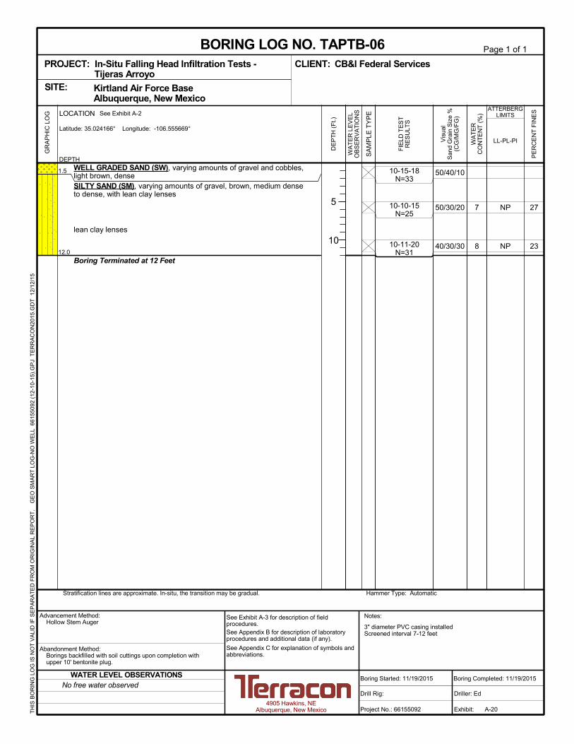
3" diameter PVC casing installedScreened interval 7-12 feet
27
23
7
8
NP
NP
50/40/10
50/30/20
40/30/30
10-15-18N=33
10-10-15N=25
10-11-20N=31
1.5
12.0
WELL GRADED SAND (SW), varying amounts of gravel and cobbles,light brown, denseSILTY SAND (SM), varying amounts of gravel, brown, medium denseto dense, with lean clay lenses
lean clay lenses
Boring Terminated at 12 Feet
Hammer Type: AutomaticStratification lines are approximate. In-situ, the transition may be gradual.
GR
AP
HIC
LO
G
TH
IS B
OR
ING
LO
G IS
NO
T V
ALI
D IF
SE
PA
RA
TE
D F
RO
M O
RIG
INA
L R
EP
OR
T.
G
EO
SM
AR
T L
OG
-NO
WE
LL 6
615
509
2 (1
2-10
-15)
.GP
J T
ER
RA
CO
N20
15.G
DT
12/
12/1
5
Kirtland Air Force Base Albuquerque, New MexicoSITE:
Page 1 of 1
Advancement Method:Hollow Stem Auger
Abandonment Method:Borings backfilled with soil cuttings upon completion withupper 10' bentonite plug.
4905 Hawkins, NEAlbuquerque, New Mexico
Notes:
Project No.: 66155092
Drill Rig:
Boring Started: 11/19/2015
BORING LOG NO. TAPTB-06CB&I Federal ServicesCLIENT:
Driller: Ed
Boring Completed: 11/19/2015
Exhibit: A-20
See Exhibit A-3 for description of fieldprocedures.See Appendix B for description of laboratoryprocedures and additional data (if any).
See Appendix C for explanation of symbols andabbreviations.
PROJECT: In-Situ Falling Head Infiltration Tests -Tijeras Arroyo
PE
RC
EN
T F
INE
S
WA
TE
RC
ON
TE
NT
(%
)
ATTERBERGLIMITS
LL-PL-PI
SA
MP
LE T
YP
E
WA
TE
R L
EV
EL
OB
SE
RV
AT
ION
S
DE
PT
H (
Ft.)
5
10
Vis
ual
San
d G
rain
Siz
e %
(CG
/MG
/FG
)
FIE
LD T
ES
TR
ES
ULT
S
DEPTH
LOCATION See Exhibit A-2
Latitude: 35.024166° Longitude: -106.555669°
No free water observedWATER LEVEL OBSERVATIONS

3" diameter PVC casing installedScreened interval 0-5 feet
27NP
50/40/10
30/40/30
4-15-18N=33
6-15-15N=30
1.5
6.5
WELL GRADED SAND (SW), varying amounts of gravel and cobbles,light brown, denseSILTY SAND (SM), varying amounts of gravel, brown, dense, with leanclay lenses
Boring Terminated at 6.5 Feet
Hammer Type: AutomaticStratification lines are approximate. In-situ, the transition may be gradual.
GR
AP
HIC
LO
G
TH
IS B
OR
ING
LO
G IS
NO
T V
ALI
D IF
SE
PA
RA
TE
D F
RO
M O
RIG
INA
L R
EP
OR
T.
G
EO
SM
AR
T L
OG
-NO
WE
LL 6
615
509
2 (1
2-10
-15)
.GP
J T
ER
RA
CO
N20
15.G
DT
12/
12/1
5
Kirtland Air Force Base Albuquerque, New MexicoSITE:
Page 1 of 1
Advancement Method:Hollow Stem Auger
Abandonment Method:Borings backfilled with bentonite upon completion.
4905 Hawkins, NEAlbuquerque, New Mexico
Notes:
Project No.: 66155092
Drill Rig:
Boring Started: 11/19/2015
BORING LOG NO. TAPTB-06ACB&I Federal ServicesCLIENT:
Driller: Ed
Boring Completed: 11/19/2015
Exhibit: A-21
See Exhibit A-3 for description of fieldprocedures.See Appendix B for description of laboratoryprocedures and additional data (if any).
See Appendix C for explanation of symbols andabbreviations.
PROJECT: In-Situ Falling Head Infiltration Tests -Tijeras Arroyo
PE
RC
EN
T F
INE
S
WA
TE
RC
ON
TE
NT
(%
)
ATTERBERGLIMITS
LL-PL-PI
SA
MP
LE T
YP
E
WA
TE
R L
EV
EL
OB
SE
RV
AT
ION
S
DE
PT
H (
Ft.)
5
Vis
ual
San
d G
rain
Siz
e %
(CG
/MG
/FG
)
FIE
LD T
ES
TR
ES
ULT
S
DEPTH
LOCATION See Exhibit A-2
Latitude: 35.024196° Longitude: -106.555599°
No free water observedWATER LEVEL OBSERVATIONS
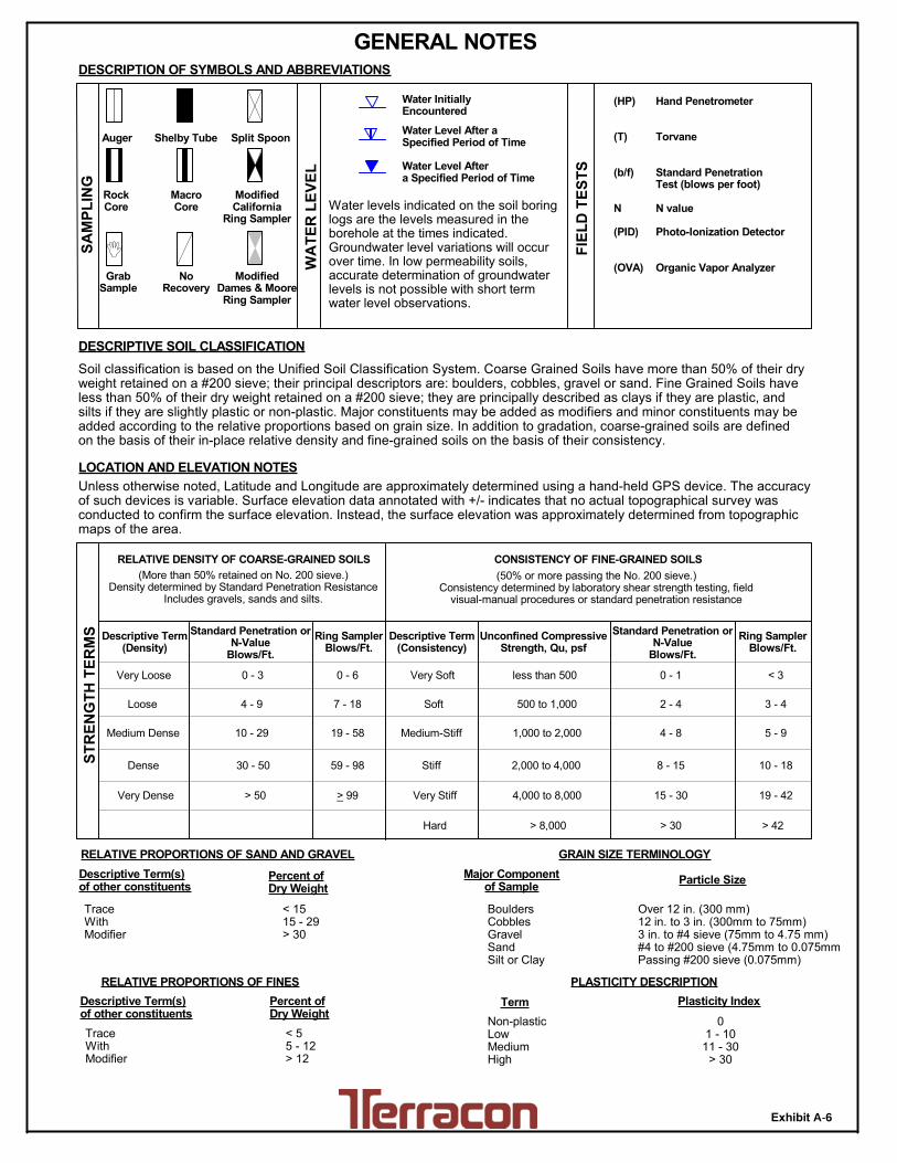
TraceWithModifier
Water Level Aftera Specified Period of Time
GRAIN SIZE TERMINOLOGYRELATIVE PROPORTIONS OF SAND AND GRAVEL
TraceWithModifier
Standard Penetration orN-Value
Blows/Ft.
Descriptive Term(Consistency)
Loose
Very Stiff
Standard Penetration orN-Value
Blows/Ft.
Ring SamplerBlows/Ft.
Ring SamplerBlows/Ft.
Medium Dense
Dense
Very Dense
0 - 1 < 3
4 - 9 2 - 4 3 - 4
Medium-Stiff 5 - 9
30 - 50
WA
TE
R L
EV
EL
Auger Shelby Tube Split Spoon
RockCore
8 - 15
PLASTICITY DESCRIPTION
Term
< 1515 - 29> 30
Descriptive Term(s)of other constituents
Water InitiallyEncountered
Water Level After aSpecified Period of Time
Major Componentof Sample
Percent ofDry Weight
(More than 50% retained on No. 200 sieve.)Density determined by Standard Penetration Resistance
Includes gravels, sands and silts.
Hard
Very Loose 0 - 3 0 - 6 Very Soft
7 - 18 Soft
10 - 29 19 - 58
59 - 98 Stiff
less than 500
500 to 1,000
1,000 to 2,000
MacroCore
2,000 to 4,000
4,000 to 8,000> 99
LOCATION AND ELEVATION NOTES
SA
MP
LIN
G
FIE
LD
TE
ST
S
DESCRIPTION OF SYMBOLS AND ABBREVIATIONS
Descriptive Term(Density)
Non-plasticLowMediumHigh
BouldersCobblesGravelSandSilt or Clay
10 - 18
> 50 15 - 30 19 - 42
> 30 > 42
_
CONSISTENCY OF FINE-GRAINED SOILS
Hand Penetrometer
Torvane
Standard PenetrationTest (blows per foot)
N value
Photo-Ionization Detector
Organic Vapor Analyzer
(HP)
(T)
(b/f)
N
(PID)
(OVA)
(50% or more passing the No. 200 sieve.)Consistency determined by laboratory shear strength testing, field
visual-manual procedures or standard penetration resistance
DESCRIPTIVE SOIL CLASSIFICATION
> 8,000
Unless otherwise noted, Latitude and Longitude are approximately determined using a hand-held GPS device. The accuracyof such devices is variable. Surface elevation data annotated with +/- indicates that no actual topographical survey wasconducted to confirm the surface elevation. Instead, the surface elevation was approximately determined from topographicmaps of the area.
Soil classification is based on the Unified Soil Classification System. Coarse Grained Soils have more than 50% of their dryweight retained on a #200 sieve; their principal descriptors are: boulders, cobbles, gravel or sand. Fine Grained Soils haveless than 50% of their dry weight retained on a #200 sieve; they are principally described as clays if they are plastic, andsilts if they are slightly plastic or non-plastic. Major constituents may be added as modifiers and minor constituents may beadded according to the relative proportions based on grain size. In addition to gradation, coarse-grained soils are definedon the basis of their in-place relative density and fine-grained soils on the basis of their consistency.
Plasticity Index
01 - 1011 - 30
> 30
RELATIVE PROPORTIONS OF FINES
Descriptive Term(s)of other constituents
Percent ofDry Weight
< 55 - 12> 12
RELATIVE DENSITY OF COARSE-GRAINED SOILS
Particle Size
Over 12 in. (300 mm)12 in. to 3 in. (300mm to 75mm)3 in. to #4 sieve (75mm to 4.75 mm)#4 to #200 sieve (4.75mm to 0.075mmPassing #200 sieve (0.075mm)
ST
RE
NG
TH
TE
RM
S Unconfined CompressiveStrength, Qu, psf
4 - 8
GENERAL NOTES
ModifiedCalifornia
Ring Sampler
GrabSample
ModifiedDames & MooreRing Sampler
NoRecovery
Water levels indicated on the soil boringlogs are the levels measured in theborehole at the times indicated.Groundwater level variations will occurover time. In low permeability soils,accurate determination of groundwaterlevels is not possible with short termwater level observations.
Exhibit A-6

UNIFIED SOIL CLASSIFICATION SYSTEM
Criteria for Assigning Group Symbols and Group Names Using Laboratory Tests A Soil Classification
Group Symbol Group Name B
Coarse Grained Soils: More than 50% retained on No. 200 sieve
Gravels: More than 50% of coarse fraction retained on No. 4 sieve
Clean Gravels: Less than 5% fines C
Cu 4 and 1 Cc 3 E GW Well-graded gravel F Cu 4 and/or 1 Cc 3 E GP Poorly graded gravel F
Gravels with Fines: More than 12% fines C
Fines classify as ML or MH GM Silty gravel F,G,H Fines classify as CL or CH GC Clayey gravel F,G,H
Sands: 50% or more of coarse fraction passes No. 4 sieve
Clean Sands: Less than 5% fines D
Cu 6 and 1 Cc 3 E SW Well-graded sand I Cu 6 and/or 1 Cc 3 E SP Poorly graded sand I
Sands with Fines: More than 12% fines D
Fines classify as ML or MH SM Silty sand G,H,I Fines classify as CL or CH SC Clayey sand G,H,I
Fine-Grained Soils: 50% or more passes the No. 200 sieve
Silts and Clays: Liquid limit less than 50
Inorganic: PI 7 and plots on or above “A” line J CL Lean clay K,L,M PI 4 or plots below “A” line J ML Silt K,L,M
Organic: Liquid limit - oven dried
0.75 OL Organic clay K,L,M,N
Liquid limit - not dried Organic silt K,L,M,O
Silts and Clays: Liquid limit 50 or more
Inorganic: PI plots on or above “A” line CH Fat clay K,L,M PI plots below “A” line MH Elastic Silt K,L,M
Organic: Liquid limit - oven dried
0.75 OH Organic clay K,L,M,P
Liquid limit - not dried Organic silt K,L,M,Q Highly organic soils: Primarily organic matter, dark in color, and organic odor PT Peat
A Based on the material passing the 3-inch (75-mm) sieve B If field sample contained cobbles or boulders, or both, add “with cobbles
or boulders, or both” to group name. C Gravels with 5 to 12% fines require dual symbols: GW-GM well-graded
gravel with silt, GW-GC well-graded gravel with clay, GP-GM poorly graded gravel with silt, GP-GC poorly graded gravel with clay.
D Sands with 5 to 12% fines require dual symbols: SW-SM well-graded sand with silt, SW-SC well-graded sand with clay, SP-SM poorly graded sand with silt, SP-SC poorly graded sand with clay
E Cu = D60/D10 Cc = 6010
2
30
DxD
)(D
F If soil contains 15% sand, add “with sand” to group name. G If fines classify as CL-ML, use dual symbol GC-GM, or SC-SM.
H If fines are organic, add “with organic fines” to group name. I If soil contains 15% gravel, add “with gravel” to group name. J If Atterberg limits plot in shaded area, soil is a CL-ML, silty clay. K If soil contains 15 to 29% plus No. 200, add “with sand” or “with gravel,”
whichever is predominant. L If soil contains 30% plus No. 200 predominantly sand, add “sandy” to
group name. M If soil contains 30% plus No. 200, predominantly gravel, add
“gravelly” to group name. N PI 4 and plots on or above “A” line. O PI 4 or plots below “A” line. P PI plots on or above “A” line. Q PI plots below “A” line.
Exhibit A-7

APPENDIX B
LABORATORY TESTING

0
5
10
15
20
25
30
35
40
45
50
55
60
65
70
75
80
85
90
95
100
0.0010.010.1110100
%Fines
LL PL PI
41 3/4 1/2 60
fine
TAB-01
TAB-01
TAB-02
TAB-03
TAB-03
56.35
GRAIN SIZE IN MILLIMETERS
PE
RC
EN
T F
INE
R B
Y W
EIG
HT
coarse fine
HYDROMETERU.S. SIEVE OPENING IN INCHES U.S. SIEVE NUMBERS
20
22
NP
NP
NP
13
6
NP
NP
NP
10.73
D100
Cc Cu
30.7
35.1
11.8
21.3
24.0
SILT OR CLAY
4
%Sand%GravelD30 D10
TAB-01
TAB-01
TAB-02
TAB-03
TAB-03
LEAN CLAY with SAND(CL)
SILTY CLAY with SAND(CL-ML)
SILTY SAND(SM)
SANDY SILT(ML)
SANDY SILT(ML)
33
28
NP
NP
NP
0.004
0.002
0.048
0.033
0.03
0.049
0.039
0.11
0.071
0.08
4.75
4.75
12.5
2.36
4.75
6 16 20 30 40 501.5 2006 810
0.0
0.0
7.2
0.0
0.0
0.002
14
5 - 6.5
15 - 16.5
15 - 16.5
10 - 11.5
15 - 16.5
3/8 3 100 1403 2
COBBLESGRAVEL SAND
USCS Classification
42.5
49.7
35.8
40.9
32.9
26.7
15.2
45.3
37.9
43.2
D60
coarse medium
Boring ID Depth
Boring ID Depth
GRAIN SIZE DISTRIBUTIONASTM D422
5 - 6.5
15 - 16.5
15 - 16.5
10 - 11.5
15 - 16.5
PROJECT NUMBER: 66155092PROJECT: In-Situ Falling Head Infiltration
Tests - Tijeras Arroyo
SITE: Kirtland Air Force Base Albuquerque, New Mexico
CLIENT: CB&I Federal Services
EXHIBIT: B-14905 Hawkins, NE
Albuquerque, New Mexico
LAB
OR
AT
OR
Y T
ES
TS
AR
E N
OT
VA
LID
IF S
EP
AR
AT
ED
FR
OM
OR
IGIN
AL
RE
PO
RT
.
GR
AIN
SIZ
E: U
SC
S-2
661
550
92 (
12-1
0-1
5).G
PJ
TE
RR
AC
ON
2012
.GD
T
12/1
2/15

0
5
10
15
20
25
30
35
40
45
50
55
60
65
70
75
80
85
90
95
100
0.0010.010.1110100
%Fines
LL PL PI
41 3/4 1/2 60
fine
TAB-04
TAB-05
TAB-06
TAB-06
TAPTB-02A
118.49
GRAIN SIZE IN MILLIMETERS
PE
RC
EN
T F
INE
R B
Y W
EIG
HT
coarse fine
HYDROMETERU.S. SIEVE OPENING IN INCHES U.S. SIEVE NUMBERS
19
16
69
NP
20
4
3
NP
NP
4
1.84
D100
Cc Cu
12.5
9.8
13.8
21.5
22.3
SILT OR CLAY
4
%Sand%GravelD30 D10
TAB-04
TAB-05
TAB-06
TAB-06
TAPTB-02A
SILTY, CLAYEY SAND with GRAVEL(SC-SM)
SILTY SAND(SM)
SILTY SAND(SM)
SANDY SILT(ML)
SANDY SILTY CLAY(CL-ML)
23
19
23
NP
24
0.073
0.095
0.064
0.025
0.027
0.733
0.765
0.482
0.083
0.076
12.5
12.5
12.5
4.75
4.75
6 16 20 30 40 501.5 2006 810
16.7
10.8
12.1
0.0
0.0
0.006
14
10 - 11.5
15 - 16.5
15 - 16.5
25 - 26.5
5 - 6.5
3/8 3 100 1403 2
COBBLESGRAVEL SAND
USCS Classification
17.9
15.7
19.0
33.8
37.2
52.9
63.7
55.2
44.7
40.5
D60
coarse medium
Boring ID Depth
Boring ID Depth
GRAIN SIZE DISTRIBUTIONASTM D422
10 - 11.5
15 - 16.5
15 - 16.5
25 - 26.5
5 - 6.5
PROJECT NUMBER: 66155092PROJECT: In-Situ Falling Head Infiltration
Tests - Tijeras Arroyo
SITE: Kirtland Air Force Base Albuquerque, New Mexico
CLIENT: CB&I Federal Services
EXHIBIT: B-24905 Hawkins, NE
Albuquerque, New Mexico
LAB
OR
AT
OR
Y T
ES
TS
AR
E N
OT
VA
LID
IF S
EP
AR
AT
ED
FR
OM
OR
IGIN
AL
RE
PO
RT
.
GR
AIN
SIZ
E: U
SC
S-2
661
550
92 (
12-1
0-1
5).G
PJ
TE
RR
AC
ON
2012
.GD
T
12/1
2/15
0
5
10
15
20
25
30
35
40
45
50
55
60
65
70
75
80
85
90
95
100
0.0010.010.1110100
26.5
%Fines
LL PL PI
41 3/4 1/2 60
fine
TAPTB-03A
TAPTB-04A
TAPTB-05A
TAPTB-06
TAPTB-06
39.69
50.51
32.70
GRAIN SIZE IN MILLIMETERS
PE
RC
EN
T F
INE
R B
Y W
EIG
HT
coarse fine
HYDROMETERU.S. SIEVE OPENING IN INCHES U.S. SIEVE NUMBERS
18
NP
NP
NP
NP
16
NP
NP
NP
NP
0.25
0.62
0.31
D100
Cc Cu
29.7
6.4
8.3
6.9
SILT OR CLAY
4
%Sand%GravelD30 D10
TAPTB-03A
TAPTB-04A
TAPTB-05A
TAPTB-06
TAPTB-06
SANDY LEAN CLAY(CL)
SILTY SAND with GRAVEL(SM)
SILTY SAND(SM)
SILTY SAND with GRAVEL(SM)
SILTY SAND with GRAVEL(SM)
34
NP
NP
NP
NP
0.005
0.117
0.087
0.094
0.118
0.068
1.463
0.79
1.174
1.213
9.5
19
12.5
12.5
19
6 16 20 30 40 501.5 2006 810
2.5
21.8
9.9
20.9
17.2
0.037
0.016
0.037
14
5 - 6.5
5 - 6.5
5 - 6.5
5 - 6.5
10 - 11.5
3/8 3 100 1403 2
COBBLESGRAVEL SAND
USCS Classification
32.8
16.4
19.3
16.0
35.1
55.4
62.5
52.6
59.9
D60
coarse medium
Boring ID Depth
Boring ID Depth
GRAIN SIZE DISTRIBUTIONASTM D422
5 - 6.5
5 - 6.5
5 - 6.5
5 - 6.5
10 - 11.5
PROJECT NUMBER: 66155092PROJECT: In-Situ Falling Head Infiltration
Tests - Tijeras Arroyo
SITE: Kirtland Air Force Base Albuquerque, New Mexico
CLIENT: CB&I Federal Services
EXHIBIT: B-34905 Hawkins, NE
Albuquerque, New Mexico
LAB
OR
AT
OR
Y T
ES
TS
AR
E N
OT
VA
LID
IF S
EP
AR
AT
ED
FR
OM
OR
IGIN
AL
RE
PO
RT
.
GR
AIN
SIZ
E: U
SC
S-2
661
550
92 (
12-1
0-1
5).G
PJ
TE
RR
AC
ON
2012
.GD
T
12/1
2/15

0
5
10
15
20
25
30
35
40
45
50
55
60
65
70
75
80
85
90
95
100
0.0010.010.1110100
%Fines
LL PL PI
41 3/4 1/2 60
fine
TAPTB-06A
45.51
GRAIN SIZE IN MILLIMETERS
PE
RC
EN
T F
INE
R B
Y W
EIG
HT
coarse fine
HYDROMETERU.S. SIEVE OPENING IN INCHES U.S. SIEVE NUMBERS
NP NP 0.29
D100
Cc Cu
7.7
SILT OR CLAY
4
%Sand%GravelD30 D10
TAPTB-06A SILTY SAND with GRAVEL(SM) NP
0.0941.17412.5
6 16 20 30 40 501.5 2006 810
20.90.026
14
5 - 6.5
3/8 3 100 1403 2
COBBLESGRAVEL SAND
USCS Classification
18.952.6
D60
coarse medium
Boring ID Depth
Boring ID Depth
GRAIN SIZE DISTRIBUTIONASTM D422
5 - 6.5
PROJECT NUMBER: 66155092PROJECT: In-Situ Falling Head Infiltration
Tests - Tijeras Arroyo
SITE: Kirtland Air Force Base Albuquerque, New Mexico
CLIENT: CB&I Federal Services
EXHIBIT: B-44905 Hawkins, NE
Albuquerque, New Mexico
LAB
OR
AT
OR
Y T
ES
TS
AR
E N
OT
VA
LID
IF S
EP
AR
AT
ED
FR
OM
OR
IGIN
AL
RE
PO
RT
.
GR
AIN
SIZ
E: U
SC
S-2
661
550
92 (
12-1
0-1
5).G
PJ
TE
RR
AC
ON
2012
.GD
T
12/1
2/15

APPENDIX C
PERCOLATION AND FALLING HEAD HYDRAULIC
CONDUCTIVITY CALCULATIONS
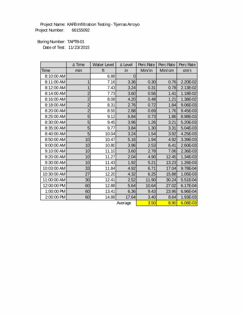
KAFB Infiltration Testing - Tijerras Arroyo66155092
TAPTB-0111/23/2015
Δ Time Water Level Δ Level Perc Rate Perc Rate Perc RateTime min ft in Min/in Min/cm cm/s
8:10:00 AM 6.88 08:11:00 AM 1 7.16 3.36 0.30 0.76 2.20E-028:12:00 AM 1 7.43 3.24 0.31 0.78 2.13E-028:14:00 AM 2 7.73 3.60 0.56 1.41 1.18E-028:16:00 AM 2 8.08 4.20 0.48 1.21 1.38E-028:18:00 AM 2 8.31 2.76 0.72 1.84 9.06E-038:20:00 AM 2 8.55 2.88 0.69 1.76 9.45E-038:25:00 AM 5 9.12 6.84 0.73 1.86 8.98E-038:30:00 AM 5 9.45 3.96 1.26 3.21 5.20E-038:35:00 AM 5 9.77 3.84 1.30 3.31 5.04E-038:40:00 AM 5 10.04 3.24 1.54 3.92 4.25E-038:50:00 AM 10 10.47 5.16 1.94 4.92 3.39E-039:00:00 AM 10 10.80 3.96 2.53 6.41 2.60E-039:10:00 AM 10 11.10 3.60 2.78 7.06 2.36E-039:20:00 AM 10 11.27 2.04 4.90 12.45 1.34E-039:30:00 AM 10 11.43 1.92 5.21 13.23 1.26E-03
10:03:00 AM 33 11.84 4.92 6.71 17.04 9.78E-0410:30:00 AM 27 12.20 4.32 6.25 15.88 1.05E-0311:00:00 AM 30 12.41 2.52 11.90 30.24 5.51E-0412:00:00 PM 60 12.88 5.64 10.64 27.02 6.17E-04
1:00:00 PM 60 13.41 6.36 9.43 23.96 6.96E-042:00:00 PM 60 14.88 17.64 3.40 8.64 1.93E-03
Average 3.50 8.90 6.08E-03
Project Name:Project Number:
Boring Number:Date of Test:
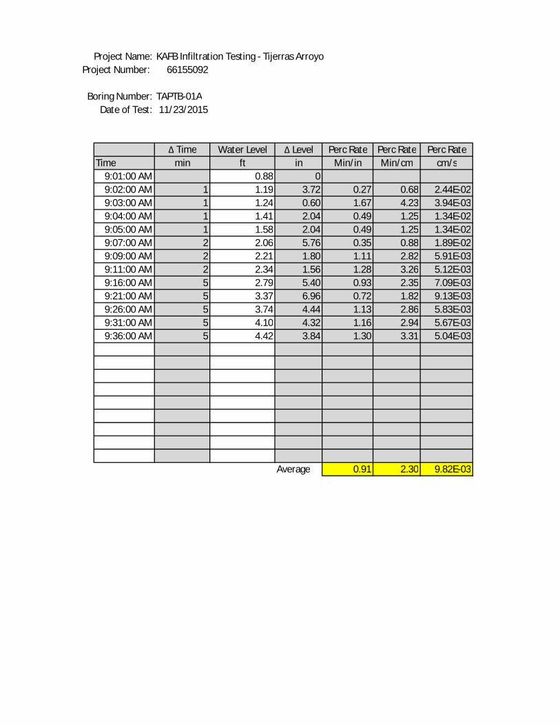
KAFB Infiltration Testing - Tijerras Arroyo66155092
TAPTB-01A11/23/2015
Δ Time Water Level Δ Level Perc Rate Perc Rate Perc RateTime min ft in Min/in Min/cm cm/s
9:01:00 AM 0.88 09:02:00 AM 1 1.19 3.72 0.27 0.68 2.44E-029:03:00 AM 1 1.24 0.60 1.67 4.23 3.94E-039:04:00 AM 1 1.41 2.04 0.49 1.25 1.34E-029:05:00 AM 1 1.58 2.04 0.49 1.25 1.34E-029:07:00 AM 2 2.06 5.76 0.35 0.88 1.89E-029:09:00 AM 2 2.21 1.80 1.11 2.82 5.91E-039:11:00 AM 2 2.34 1.56 1.28 3.26 5.12E-039:16:00 AM 5 2.79 5.40 0.93 2.35 7.09E-039:21:00 AM 5 3.37 6.96 0.72 1.82 9.13E-039:26:00 AM 5 3.74 4.44 1.13 2.86 5.83E-039:31:00 AM 5 4.10 4.32 1.16 2.94 5.67E-039:36:00 AM 5 4.42 3.84 1.30 3.31 5.04E-03
Average 0.91 2.30 9.82E-03
Project Name:Project Number:
Boring Number:Date of Test:

Project Name: KAFB Infiltration Testing - Tijerras ArroyoProject Number: 66155092
Boring Number: TAPTB-02Date of Test: 11/23/2015
Δ Time Water Level Δ Level Perc Rate Perc Rate Perc RateTime min ft in Min/in Min/cm cm/s10:16:00 AM 11.70 010:17:00 AM 1 11.86 1.92 0.52 1.32 1.26E-0210:18:00 AM 1 12.00 1.68 0.60 1.51 1.10E-0210:19:00 AM 1 12.15 1.80 0.56 1.41 1.18E-0210:21:00 AM 2 12.35 2.40 0.83 2.12 7.87E-0310:23:00 AM 2 12.52 2.04 0.98 2.49 6.69E-0310:28:00 AM 5 12.91 4.68 1.07 2.71 6.14E-0310:33:00 AM 5 13.20 3.48 1.44 3.65 4.57E-0310:38:00 AM 5 13.49 3.48 1.44 3.65 4.57E-0310:48:00 AM 10 13.86 4.44 2.25 5.72 2.91E-0310:58:00 AM 10 14.22 4.32 2.31 5.88 2.83E-0311:08:00 AM 10 14.55 3.96 2.53 6.41 2.60E-0311:38:00 AM 30 15.30 9.00 3.33 8.47 1.97E-0312:08:00 PM 30 15.85 6.60 4.55 11.55 1.44E-03
1:08:00 PM 60 16.62 9.24 6.49 16.49 1.01E-032:08:00 PM 60 17.71 13.08 4.59 11.65 1.43E-033:08:00 PM 60 18.65 11.28 5.32 13.51 1.23E-033:15:00 PM 60 18.77 1.44 41.67 105.83 1.57E-04
Average 4.73 12.02 4.76E-03

KAFB Infiltration Testing - Tijerras Arroyo66155092
TAPTB-02A11/23/2015
Δ Time Water Level Δ Level Perc Rate Perc Rate Perc RateTime min ft in Min/in Min/cm cm/s10:43:00 AM 1.10 010:44:00 AM 1 1.32 2.64 0.38 0.96 1.73E-0210:45:00 AM 1 1.41 1.08 0.93 2.35 7.09E-0310:46:00 AM 1 1.51 1.20 0.83 2.12 7.87E-0310:47:00 AM 1 1.61 1.20 0.83 2.12 7.87E-0310:49:00 AM 2 2.03 5.04 0.40 1.01 1.65E-0210:51:00 AM 2 2.39 4.32 0.46 1.18 1.42E-0210:53:00 AM 2 2.65 3.12 0.64 1.63 1.02E-0210:58:00 AM 5 3.02 4.44 1.13 2.86 5.83E-0311:04:00 AM 6 3.38 4.32 1.39 3.53 4.72E-0311:08:00 AM 4 3.54 1.92 2.08 5.29 3.15E-0311:13:00 AM 5 3.73 2.28 2.19 5.57 2.99E-0311:18:00 AM 5 3.84 1.32 3.79 9.62 1.73E-0311:28:00 AM 10 4.01 2.04 4.90 12.45 1.34E-0311:38:00 AM 10 4.16 1.80 5.56 14.11 1.18E-0311:54:00 AM 16 4.34 2.16 7.41 18.81 8.86E-0412:02:00 PM 8 4.42 0.96 8.33 21.17 7.87E-04
Average 2.58 6.55 6.48E-03
Project Name:Project Number:
Boring Number:Date of Test:

KAFB Infiltration Testing - Tijerras Arroyo66155092
TAPTB-0311/24 and 25/2015
Δ Time Water Level Δ Level Perc Rate Perc Rate Perc RateTime min ft in Min/in Min/cm cm/s
7:36:00 AM 5.30 07:37:00 AM 1 5.33 0.36 2.78 7.06 2.36E-037:39:00 AM 2 5.40 0.84 2.38 6.05 2.76E-037:41:00 AM 2 5.53 1.56 1.28 3.26 5.12E-037:46:00 AM 5 5.76 2.76 1.81 4.60 3.62E-037:51:00 AM 5 5.92 1.92 2.60 6.61 2.52E-038:01:00 AM 10 5.96 0.48 20.83 52.92 3.15E-048:31:00 AM 30 6.58 7.44 4.03 10.24 1.63E-039:01:00 AM 30 7.08 6.00 5.00 12.70 1.31E-039:55:00 AM 54 7.68 7.20 7.50 19.05 8.75E-04
10:55:00 AM 60 8.26 6.96 8.62 21.90 7.61E-0411:55:00 AM 60 8.68 5.04 11.90 30.24 5.51E-0412:55:00 PM 60 9.06 4.56 13.16 33.42 4.99E-04
1:52:00 PM 57 9.50 5.28 10.80 27.42 6.08E-042:54:00 PM 62 9.90 4.80 12.92 32.81 5.08E-043:55:00 PM 61 10.35 5.40 11.30 28.69 5.81E-044:55:00 PM 60 10.93 6.96 8.62 21.90 7.61E-04
7:32:00 AM* 877 14.33 40.80 21.50 54.60 3.05E-04
Average 8.65 21.97 1.48E-03*11/25/15
Project Name:Project Number:
Boring Number:Date of Test:
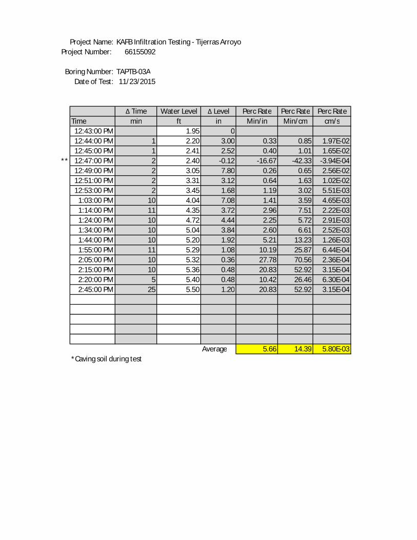
KAFB Infiltration Testing - Tijerras Arroyo66155092
TAPTB-03A11/23/2015
Δ Time Water Level Δ Level Perc Rate Perc Rate Perc RateTime min ft in Min/in Min/cm cm/s12:43:00 PM 1.95 012:44:00 PM 1 2.20 3.00 0.33 0.85 1.97E-0212:45:00 PM 1 2.41 2.52 0.40 1.01 1.65E-02
** 12:47:00 PM 2 2.40 -0.12 -16.67 -42.33 -3.94E-0412:49:00 PM 2 3.05 7.80 0.26 0.65 2.56E-0212:51:00 PM 2 3.31 3.12 0.64 1.63 1.02E-0212:53:00 PM 2 3.45 1.68 1.19 3.02 5.51E-03
1:03:00 PM 10 4.04 7.08 1.41 3.59 4.65E-031:14:00 PM 11 4.35 3.72 2.96 7.51 2.22E-031:24:00 PM 10 4.72 4.44 2.25 5.72 2.91E-031:34:00 PM 10 5.04 3.84 2.60 6.61 2.52E-031:44:00 PM 10 5.20 1.92 5.21 13.23 1.26E-031:55:00 PM 11 5.29 1.08 10.19 25.87 6.44E-042:05:00 PM 10 5.32 0.36 27.78 70.56 2.36E-042:15:00 PM 10 5.36 0.48 20.83 52.92 3.15E-042:20:00 PM 5 5.40 0.48 10.42 26.46 6.30E-042:45:00 PM 25 5.50 1.20 20.83 52.92 3.15E-04
Average 5.66 14.39 5.80E-03*Caving soil during test
Project Name:Project Number:
Boring Number:Date of Test:

KAFB Infiltration Testing - Tijerras Arroyo66155092
TAPTB-0411/24 and 25/2015
Δ Time Water Level Δ Level Perc Rate Perc Rate Perc RateTime min ft in Min/in Min/cm cm/s
8:00:00 AM 6.45 08:01:00 AM 1 7.03 6.96 0.14 0.36 4.57E-028:02:00 AM 1 7.14 1.32 0.76 1.92 8.66E-038:03:00 AM 1 7.20 0.72 1.39 3.53 4.72E-038:04:00 AM 1 7.24 0.48 2.08 5.29 3.15E-038:06:00 AM 2 7.30 0.72 2.78 7.06 2.36E-038:08:00 AM 2 7.33 0.36 5.56 14.11 1.18E-03
** 8:10:00 AM 2 7.00 -3.96 -0.51 -1.28 -1.30E-028:15:00 AM 5 7.34 4.08 1.23 3.11 5.35E-038:20:00 AM 5 7.45 1.32 3.79 9.62 1.73E-038:30:00 AM 10 7.57 1.44 6.94 17.64 9.45E-049:00:00 AM 30 7.87 3.60 8.33 21.17 7.87E-04
10:00:00 AM 60 8.45 6.96 8.62 21.90 7.61E-0411:00:00 AM 60 8.95 6.00 10.00 25.40 6.56E-0412:00:00 PM 60 9.00 0.60 100.00 254.00 6.56E-05
1:00:00 PM 60 9.32 3.84 15.63 39.69 4.20E-042:00:00 PM 60 9.52 2.40 25.00 63.50 2.62E-043:00:00 PM 60 9.97 5.40 11.11 28.22 5.91E-04
** 4:00:00 PM 60 9.88 -1.08 -55.56 -141.11 -1.18E-045:00:00 PM 60 9.92 0.48 125.00 317.50 5.25E-05
7:39:00 AM* 879 10.21 3.48 252.59 641.57 2.60E-05
Average 26.24 66.66 3.21E-03*11/25/15**Caving soil during test
Project Name:Project Number:
Boring Number:Date of Test:

KAFB Infiltration Testing - Tijerras Arroyo66155092
TAPTB-04A11/24 and 25/2015
Δ Time Water Level Δ Level Perc Rate Perc Rate Perc RateTime min ft in Min/in Min/cm cm/s11:15:00 AM 1.58 011:16:00 AM 1 1.61 0.36 2.78 7.06 2.36E-0311:17:00 AM 1 1.64 0.36 2.78 7.06 2.36E-0311:18:00 AM 1 1.67 0.36 2.78 7.06 2.36E-0311:20:00 AM 2 1.73 0.72 2.78 7.06 2.36E-0311:25:00 AM 5 1.82 1.08 4.63 11.76 1.42E-0311:30:00 AM 5 1.91 1.08 4.63 11.76 1.42E-0311:45:00 AM 15 2.09 2.16 6.94 17.64 9.45E-0412:00:00 PM 15 2.32 2.76 5.43 13.80 1.21E-0312:30:00 PM 30 2.55 2.76 10.87 27.61 6.04E-04
1:00:00 PM 30 2.67 1.44 20.83 52.92 3.15E-042:00:00 PM 60 2.82 1.80 33.33 84.67 1.97E-043:00:00 PM 60 2.98 1.92 31.25 79.37 2.10E-044:00:00 PM 60 3.11 1.56 38.46 97.69 1.71E-045:00:00 PM 60 3.21 1.20 50.00 127.00 1.31E-04
7:39:00 AM* 879 4.99 21.36 41.15 104.53 1.59E-04
Average 17.24 43.80 1.08E-03*11/25/15
Project Name:Project Number:
Boring Number:Date of Test:
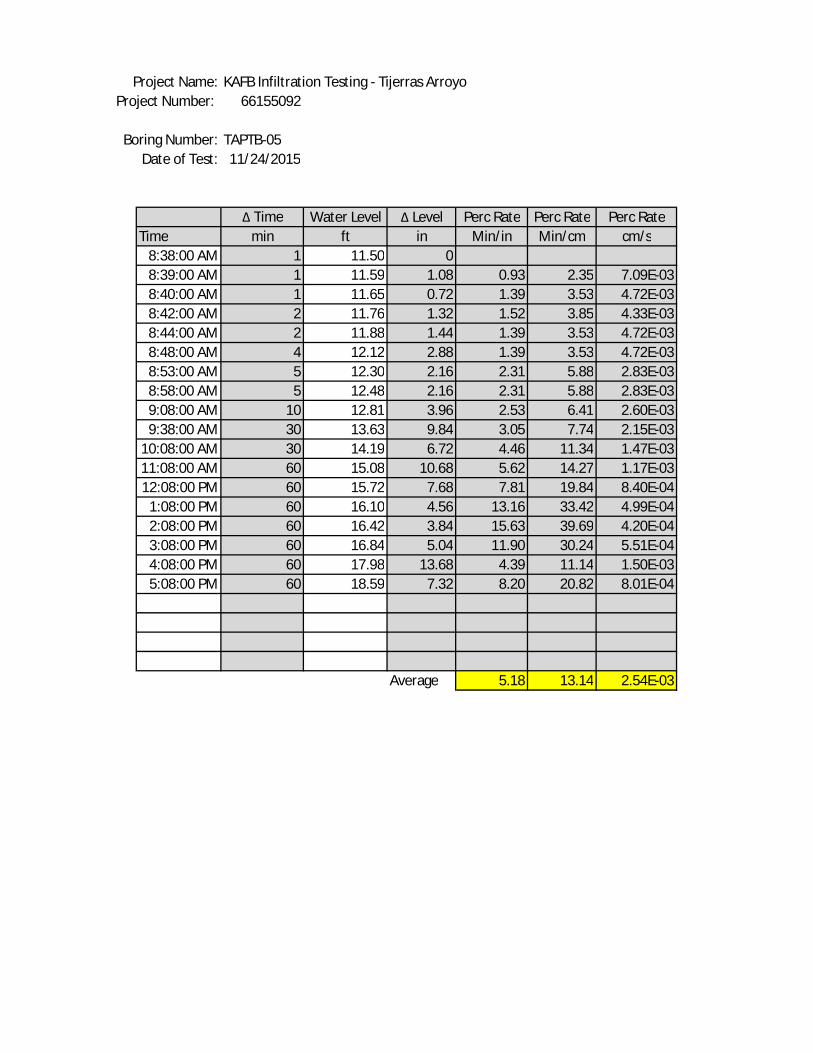
KAFB Infiltration Testing - Tijerras Arroyo66155092
TAPTB-0511/24/2015
Δ Time Water Level Δ Level Perc Rate Perc Rate Perc RateTime min ft in Min/in Min/cm cm/s
8:38:00 AM 1 11.50 08:39:00 AM 1 11.59 1.08 0.93 2.35 7.09E-038:40:00 AM 1 11.65 0.72 1.39 3.53 4.72E-038:42:00 AM 2 11.76 1.32 1.52 3.85 4.33E-038:44:00 AM 2 11.88 1.44 1.39 3.53 4.72E-038:48:00 AM 4 12.12 2.88 1.39 3.53 4.72E-038:53:00 AM 5 12.30 2.16 2.31 5.88 2.83E-038:58:00 AM 5 12.48 2.16 2.31 5.88 2.83E-039:08:00 AM 10 12.81 3.96 2.53 6.41 2.60E-039:38:00 AM 30 13.63 9.84 3.05 7.74 2.15E-03
10:08:00 AM 30 14.19 6.72 4.46 11.34 1.47E-0311:08:00 AM 60 15.08 10.68 5.62 14.27 1.17E-0312:08:00 PM 60 15.72 7.68 7.81 19.84 8.40E-04
1:08:00 PM 60 16.10 4.56 13.16 33.42 4.99E-042:08:00 PM 60 16.42 3.84 15.63 39.69 4.20E-043:08:00 PM 60 16.84 5.04 11.90 30.24 5.51E-044:08:00 PM 60 17.98 13.68 4.39 11.14 1.50E-035:08:00 PM 60 18.59 7.32 8.20 20.82 8.01E-04
Average 5.18 13.14 2.54E-03
Project Name:Project Number:
Boring Number:Date of Test:

KAFB Infiltration Testing - Tijerras Arroyo66155092
TAPTB-05A11/24 and 25/2015
Δ Time Water Level Δ Level Perc Rate Perc Rate Perc RateTime min ft in Min/in Min/cm cm/s10:25:00 AM 1.52 010:26:00 AM 1 1.55 0.36 2.78 7.06 2.36E-0310:27:00 AM 1 1.57 0.24 4.17 10.58 1.57E-0310:28:00 AM 1 1.59 0.24 4.17 10.58 1.57E-0310:30:00 AM 2 1.63 0.48 4.17 10.58 1.57E-0310:35:00 AM 5 1.71 0.96 5.21 13.23 1.26E-0310:40:00 AM 5 1.77 0.72 6.94 17.64 9.45E-0410:55:00 AM 15 1.91 1.68 8.93 22.68 7.35E-0411:10:00 AM 15 2.02 1.32 11.36 28.86 5.77E-0411:40:00 AM 30 2.20 2.16 13.89 35.28 4.72E-0412:10:00 PM 30 2.29 1.08 27.78 70.56 2.36E-04
1:10:00 PM 60 2.49 2.40 25.00 63.50 2.62E-042:10:00 PM 60 2.69 2.40 25.00 63.50 2.62E-043:10:00 PM 60 2.99 3.60 16.67 42.33 3.94E-044:10:00 PM 60 3.23 2.88 20.83 52.92 3.15E-045:10:00 PM 60 3.57 4.08 14.71 37.35 4.46E-04
7:41:00 AM* 870 5.80 26.76 32.51 82.58 2.02E-04
Average 14.01 35.58 8.25E-04*11/25/15
Project Name:Project Number:
Boring Number:Date of Test:

KAFB Infiltration Testing - Tijerras Arroyo66155092
TAPTB-0611/24 and 25/2015
Δ Time Water Level Δ Level Perc Rate Perc Rate Perc RateTime min ft in Min/in Min/cm cm/s
9:17:00 AM 1.90 09:18:00 AM 1 2.00 1.20 0.83 2.12 7.87E-039:19:00 AM 1 2.08 0.96 1.04 2.65 6.30E-039:21:00 AM 2 2.25 2.04 0.98 2.49 6.69E-039:23:00 AM 2 2.40 1.80 1.11 2.82 5.91E-039:27:00 AM 4 2.65 3.00 1.33 3.39 4.92E-039:32:00 AM 5 2.90 3.00 1.67 4.23 3.94E-039:37:00 AM 5 3.13 2.76 1.81 4.60 3.62E-039:47:00 AM 10 3.25 1.44 6.94 17.64 9.45E-04
10:17:00 AM 30 3.31 0.72 41.67 105.83 1.57E-0411:17:00 AM 60 3.94 7.56 7.94 20.16 8.27E-0412:17:00 PM 60 4.18 2.88 20.83 52.92 3.15E-04
1:17:00 PM 60 4.45 3.24 18.52 47.04 3.54E-042:17:00 PM 60 4.72 3.24 18.52 47.04 3.54E-043:17:00 PM 60 5.05 3.96 15.15 38.48 4.33E-044:17:00 PM 60 5.30 3.00 20.00 50.80 3.28E-045:17:00 PM 60 5.52 2.64 22.73 57.73 2.89E-04
7:45:00 AM* 868 7.82 27.60 31.45 79.88 2.09E-04
Average 12.50 31.75 2.56E-03*11/25/15
Project Name:Project Number:
Boring Number:Date of Test:

KAFB Infiltration Testing - Tijerras Arroyo66155092
TAPTB-06A11/24 and 25/2015
Δ Time Water Level Δ Level Perc Rate Perc Rate Perc RateTime min ft in Min/in Min/cm cm/s
9:50:00 AM 2.98 09:51:00 AM 1 3.02 0.48 2.08 5.29 3.15E-039:52:00 AM 1 3.03 0.12 8.33 21.17 7.87E-049:54:00 AM 2 3.06 0.36 5.56 14.11 1.18E-039:56:00 AM 2 3.09 0.36 5.56 14.11 1.18E-03
10:00:00 AM 4 3.13 0.48 8.33 21.17 7.87E-0410:05:00 AM 5 3.18 0.60 8.33 21.17 7.87E-0410:15:00 AM 10 3.23 0.60 16.67 42.33 3.94E-0410:45:00 AM 30 3.37 1.68 17.86 45.36 3.67E-0411:15:00 AM 30 3.47 1.20 25.00 63.50 2.62E-0412:15:00 PM 60 3.85 4.56 13.16 33.42 4.99E-04
1:15:00 PM 60 4.12 3.24 18.52 47.04 3.54E-042:15:00 PM 60 4.40 3.36 17.86 45.36 3.67E-043:15:00 PM 60 4.64 2.88 20.83 52.92 3.15E-044:15:00 PM 60 4.88 2.88 20.83 52.92 3.15E-045:15:00 PM 60 5.06 2.16 27.78 70.56 2.36E-04
7:44:00 AM* 869 6.34 15.36 56.58 143.70 1.16E-04
Average 17.08 43.38 6.94E-04*11/25/15
Project Name:Project Number:
Boring Number:Date of Test:

KAFB Infiltration Testing - Tijeras Arroyo
D d H1 H2 L T m kh (cm/s) kh (gpd/ft2)
20.32 7.62 134.7 143.3 152.4 60 1 1.32E-04 2.8
20.32 7.62 143.3 151.5 152.4 60 1 1.20E-04 2.5
20.32 7.62 151.5 160.6 152.4 120 1 6.30E-05 1.3
20.32 7.62 160.6 171.3 152.4 120 1 6.91E-05 1.5
20.32 7.62 171.3 178.3 152.4 120 1 4.31E-05 0.9
20.32 7.62 178.3 185.6 152.4 120 1 4.32E-05 0.9
20.32 7.62 185.6 203.0 152.4 300 1 3.85E-05 0.8
20.32 7.62 203.0 213.1 152.4 300 1 2.08E-05 0.4
20.32 7.62 213.1 222.8 152.4 300 1 1.92E-05 0.4
20.32 7.62 222.8 231.0 152.4 300 1 1.56E-05 0.3
20.32 7.62 231.0 244.1 152.4 600 1 1.19E-05 0.3
20.32 7.62 244.1 254.2 152.4 600 1 8.68E-06 0.2
20.32 7.62 254.2 263.3 152.4 600 1 7.60E-06 0.2
20.32 7.62 263.3 268.5 152.4 600 1 4.19E-06 0.1
20.32 7.62 268.5 273.4 152.4 600 1 3.87E-06 0.1
20.32 7.62 273.4 285.9 152.4 1980 1 2.91E-06 0.1
20.32 7.62 285.9 296.9 152.4 1620 1 3.00E-06 0.1
20.32 7.62 296.9 303.3 152.4 1800 1 1.53E-06 0.0
20.32 20.32 303.3 317.6 138.1 3600 1 1.25E-05 0.3
20.32 20.32 317.6 333.8 121.9 3600 1 1.45E-05 0.3
20.32 20.32 333.8 378.6 77.1 3600 1 4.75E-05 1.0
kh Horizontal Permeability (cm/s) and (gpd/ft2)
D Intake Diameter/Diameter of borehole (cm)
d Standpipe Diameter - Solid PVC Casing Diameter above 5 feet/Borehole Diameter below 5 feet (cm)
L Intake Length or Slotted PVC Casing Length (cm)
T Basic Time Lag - Change in time between readings (s)
m Transformation Ratio (unitless)
H1 Depth to water level (cm) at time 1
H2 Depth to water level (cm) at time 2
Note: 3" Diameter PVC Casing installed with Screened Interval From 10-15 Feet
66155092
TAPTB-01
11/23/2015
Project Name:
Project Number:
Boring Number:
Date of Test:

KAFB Infiltration Testing - Tijeras Arroyo
D d H1 H2 L T m kh (cm/s) kh (gpd/ft2)
20.32 20.32 4.0 13.4 143.0 60 1 1.94E-02 411.8
20.32 20.32 13.4 14.9 141.4 60 1 1.72E-03 36.6
20.32 20.32 14.9 20.1 136.2 60 1 4.88E-03 103.6
20.32 20.32 20.1 25.3 131.1 60 1 3.85E-03 81.6
20.32 20.32 25.3 39.9 116.4 60 1 8.22E-03 174.5
20.32 20.32 39.9 44.5 111.9 120 1 1.00E-03 21.2
20.32 20.32 44.5 48.5 107.9 120 1 8.03E-04 17.1
20.32 20.32 48.5 62.2 94.2 120 1 2.53E-03 53.8
20.32 20.32 62.2 79.9 76.5 300 1 1.14E-03 24.1
20.32 20.32 79.9 91.1 65.2 300 1 6.48E-04 13.8
20.32 20.32 91.1 102.1 54.3 300 1 6.04E-04 12.8
20.32 20.32 102.1 111.9 44.5 300 1 5.21E-04 11.1
kh Horizontal Permeability (cm/s) and (gpd/ft2)
D Intake Diameter/Diameter of borehole (cm)d Standpipe Diameter - Solid PVC Casing Diameter above 5 feet/Borehole Diameter below 5 feet (cm)
L Intake Length or Slotted PVC Casing Length (cm)
T Basic Time Lag - Change in time between readings (s)
m Transformation Ratio (unitless)
H1 Depth to water level (cm) at time 1
H2 Depth to water level (cm) at time 2
Note: 3" Diameter PVC Casing installed with Screened Interval From 0-5 Feet
Project Name:
Project Number:
Boring Number:
Date of Test:
66155092
TAPTB-01A
11/23/2015

KAFB Infiltration Testing - Tijeras Arroyo
D d H1 H2 L T m kh (cm/s) kh (gpd/ft2)
20.32 7.62 300.7 305.6 152.4 60 1 3.46E-05 0.7
20.32 7.62 305.6 309.9 152.4 60 1 2.98E-05 0.6
20.32 7.62 309.9 314.5 152.4 120 1 1.57E-05 0.3
20.32 7.62 314.5 320.5 152.4 120 1 2.06E-05 0.4
20.32 7.62 320.5 325.7 152.4 120 1 1.72E-05 0.4
20.32 7.62 325.7 337.6 152.4 120 1 3.85E-05 0.8
20.32 7.62 337.6 346.5 152.4 300 1 1.11E-05 0.2
20.32 7.62 346.5 355.3 152.4 300 1 1.08E-05 0.2
20.32 7.62 355.3 366.6 152.4 300 1 1.34E-05 0.3
20.32 7.62 366.6 377.5 152.4 300 1 1.27E-05 0.3
20.32 7.62 377.5 387.6 152.4 600 1 5.65E-06 0.1
20.32 7.62 387.6 410.5 152.4 600 1 1.23E-05 0.3
20.32 7.62 410.5 427.2 152.4 600 1 8.60E-06 0.2
20.32 7.62 427.2 450.7 152.4 600 1 1.15E-05 0.2
20.32 7.62 450.7 483.9 152.4 600 1 1.53E-05 0.3
20.32 20.32 483.9 512.6 119.2 1980 1 3.10E-05 0.7
20.32 20.32 512.6 516.2 115.5 1620 1 4.77E-06 0.1
kh Horizontal Permeability (cm/s) and (gpd/ft2)
D Intake Diameter/Diameter of borehole (cm)d Standpipe Diameter - Solid PVC Casing Diameter above 5 feet/Borehole Diameter below 5 feet (cm)L Intake Length or Slotted PVC Casing Length (cm)T Basic Time Lag - Change in time between readings (s)
m Transformation Ratio (unitless)
H1 Depth to water level (cm) at time 1
H2 Depth to water level (cm) at time 2
Note: 3" Diameter PVC Casing installed with Screened Interval From 15-20 Feet
Project Name:
Project Number:
Boring Number:
Date of Test:
66155092
TAPTB-02
11/23/2015

KAFB Infiltration Testing - Tijeras Arroyo
D d H1 H2 L T m kh (cm/s) kh (gpd/ft2)
20.32 20.32 8.1 14.8 145.7 60 1 9.46E-03 200.8
20.32 20.32 14.8 17.6 143.0 60 1 2.70E-03 57.3
20.32 20.32 17.6 20.6 139.9 60 1 2.58E-03 54.7
20.32 20.32 20.6 23.7 136.9 60 1 2.25E-03 47.8
20.32 20.32 23.7 36.5 124.1 120 1 3.75E-03 79.6
20.32 20.32 36.5 47.4 113.1 120 1 2.41E-03 51.2
20.32 20.32 47.4 55.4 105.2 120 1 1.48E-03 31.3
20.32 20.32 55.4 66.6 93.9 300 1 7.55E-04 16.0
20.32 20.32 66.6 77.6 82.9 360 1 5.53E-04 11.7
20.32 20.32 77.6 82.5 78.0 240 1 3.42E-04 7.3
20.32 20.32 82.5 88.3 72.2 300 1 3.17E-04 6.7
20.32 20.32 88.3 91.6 68.9 300 1 1.78E-04 3.8
20.32 20.32 91.6 96.8 63.7 600 1 1.36E-04 2.9
20.32 20.32 96.8 101.4 59.1 600 1 1.18E-04 2.5
20.32 20.32 101.4 106.9 53.6 960 1 8.79E-05 1.9
20.32 20.32 106.9 109.3 51.2 480 1 7.66E-05 1.6
kh Horizontal Permeability (cm/s) and (gpd/ft2)
D Intake Diameter/Diameter of borehole (cm)
d Standpipe Diameter - Solid PVC Casing Diameter above 5 feet/Borehole Diameter below 5 feet (cm)
L Intake Length or Slotted PVC Casing Length (cm)
T Basic Time Lag - Change in time between readings (s)
m Transformation Ratio (unitless)
H1 Depth to water level (cm) at time 1
H2 Depth to water level (cm) at time 2
Note: 3" Diameter PVC Casing installed with Screened Interval From 0-5 Feet
66155092
11/23/2015
Project Name:
Project Number:
Boring Number:
Date of Test:
TAPTB-02A

KAFB Infiltration Testing - Tijeras Arroyo
D d H1 H2 L T m kh (cm/s) kh (gpd/ft2)
20.32 7.62 140.6 141.5 152.4 60 1 1.39E-05 0.3
20.32 7.62 141.5 143.6 152.4 60 1 3.22E-05 0.7
20.32 7.62 143.6 147.6 152.4 120 1 2.92E-05 0.6
20.32 7.62 147.6 154.6 152.4 120 1 4.99E-05 1.1
20.32 7.62 154.6 159.5 152.4 120 1 3.34E-05 0.7
20.32 7.62 159.5 160.7 152.4 120 1 8.19E-06 0.2
20.32 7.62 160.7 179.6 152.4 300 1 4.78E-05 1.0
20.32 7.62 179.6 194.8 152.4 300 1 3.50E-05 0.7
20.32 7.62 194.8 213.1 152.4 300 1 3.86E-05 0.8
20.32 7.62 213.1 230.8 152.4 300 1 3.43E-05 0.7
20.32 7.62 230.8 243.6 152.4 600 1 1.16E-05 0.2
20.32 7.62 243.6 255.2 152.4 600 1 9.98E-06 0.2
20.32 7.62 255.2 268.6 152.4 600 1 1.10E-05 0.2
20.32 7.62 268.6 280.8 152.4 600 1 9.54E-06 0.2
20.32 7.62 280.8 294.5 152.4 600 1 1.03E-05 0.2
20.32 20.32 294.5 312.2 134.7 1980 1 2.92E-05 0.6
20.32 20.32 312.2 361.8 85.1 1620 1 1.17E-04 2.5
kh Horizontal Permeability (cm/s) and (gpd/ft2)
D Intake Diameter/Diameter of borehole (cm)d Standpipe Diameter - Solid PVC Casing Diameter above 5 feet/Borehole Diameter below 5 feet (cm)L Intake Length or Slotted PVC Casing Length (cm)T Basic Time Lag - Change in time between readings (s)m Transformation Ratio (unitless)
H1 Depth to water level (cm) at time 1
H2 Depth to water level (cm) at time 2
Note: 3" Diameter PVC Casing installed with Screened Interval From 10-15 Feet
66155092
TAPTB-03
11/23 -24/2015
Project Name:
Project Number:
Boring Number:
Date of Test:

KAFB Infiltration Testing - Tijeras Arroyo
D d H1 H2 L T m kh (cm/s) kh (gpd/ft2)
20.32 20.32 4.6 12.2 144.8 60 1 1.55E-02 328.5
20.32 20.32 12.2 18.6 138.4 60 1 6.85E-03 145.4
* 20.32 20.32 18.6 18.3 138.7 120 1 -1.34E-04 -2.8
20.32 20.32 18.3 38.1 118.9 120 1 6.53E-03 138.6
20.32 20.32 38.1 46.0 110.9 120 1 1.75E-03 37.2
20.32 20.32 46.0 50.3 106.7 120 1 8.40E-04 17.8
20.32 20.32 50.3 68.3 88.7 600 1 6.42E-04 13.6
20.32 20.32 68.3 77.7 79.2 660 1 2.63E-04 5.6
20.32 20.32 77.7 89.0 68.0 600 1 3.26E-04 6.9
20.32 20.32 89.0 98.8 58.2 600 1 2.68E-04 5.7
20.32 20.32 98.8 103.6 53.3 600 1 1.29E-04 2.7
20.32 20.32 103.6 106.4 50.6 660 1 6.48E-05 1.4
20.32 20.32 106.4 107.3 49.7 600 1 2.35E-05 0.5
20.32 20.32 107.3 108.5 48.5 600 1 3.13E-05 0.7
20.32 20.32 108.5 109.7 47.2 300 1 6.25E-05 1.3
20.32 20.32 109.7 112.8 44.2 1500 1 3.14E-05 0.7
*Caving Soil During Test
kh Horizontal Permeability (cm/s) and (gpd/ft2)
D Intake Diameter/Diameter of borehole (cm)
d Standpipe Diameter - Solid PVC Casing Diameter above 5 feet/Borehole Diameter below 5 feet (cm)
L Intake Length or Slotted PVC Casing Length (cm)
T Basic Time Lag - Change in time between readings (s)
m Transformation Ratio (unitless)
H1 Depth to water level (cm) at time 1
H2 Depth to water level (cm) at time 2
Note: 3" Diameter PVC Casing installed with Screened Interval From 0-5 Feet
66155092
TAPTB-03A
11/23/2015
Project Name:
Project Number:
Boring Number:
Date of Test:

KAFB Infiltration Testing - Tijeras Arroyo
D d H1 H2 L T m kh (cm/s) kh (gpd/ft2)
20.32 7.62 145.7 163.4 152.4 60 1 2.46E-04 5.2
20.32 7.62 163.4 166.7 152.4 60 1 4.37E-05 0.9
20.32 7.62 166.7 168.6 152.4 120 1 1.17E-05 0.2
20.32 7.62 168.6 169.8 152.4 120 1 7.75E-06 0.2
20.32 7.62 169.8 171.6 152.4 120 1 1.15E-05 0.2
20.32 7.62 171.6 172.5 152.4 120 1 5.71E-06 0.1
* 20.32 7.62 172.5 162.5 152.4 300 1 -2.58E-05 -0.5
20.32 7.62 162.5 172.8 152.4 300 1 2.66E-05 0.6
20.32 7.62 172.8 176.2 152.4 300 1 8.26E-06 0.2
20.32 7.62 176.2 179.8 152.4 300 1 8.83E-06 0.2
20.32 7.62 179.8 189.0 152.4 600 1 1.07E-05 0.2
20.32 7.62 189.0 206.7 152.4 600 1 1.92E-05 0.4
20.32 7.62 206.7 221.9 152.4 600 1 1.53E-05 0.3
20.32 7.62 221.9 223.4 152.4 600 1 1.47E-06 0.0
20.32 7.62 223.4 233.2 152.4 600 1 9.18E-06 0.2
20.32 7.62 233.2 239.3 152.4 1980 1 1.68E-06 0.0
20.32 7.62 239.3 253.0 152.4 1620 1 4.44E-06 0.1
* 20.32 7.62 253.0 250.2 152.4 1800 1 -7.81E-07 0.0
20.32 7.62 250.2 251.5 152.4 3600 1 1.74E-07 0.0
20.32 7.62 251.5 260.3 152.4 3600 1 1.24E-06 0.0
* Caving Soil During Test
kh Horizontal Permeability (cm/s) and (gpd/ft2)
D Intake Diameter/Diameter of borehole (cm)d Standpipe Diameter - Solid PVC Casing Diameter above 5 feet/Borehole Diameter below 5 feet (cm)
L Intake Length or Slotted PVC Casing Length (cm)
T Basic Time Lag - Change in time between readings (s)
m Transformation Ratio (unitless)
H1 Depth to water level (cm) at time 1
H2 Depth to water level (cm) at time 2
Note: 3" Diameter PVC Casing installed with Screened Interval From 10-15 Feet
66155092
TAPTB-04
11/24 - 25/2015
Project Name:
Project Number:
Boring Number:
Date of Test:

KAFB Infiltration Testing - Tijeras Arroyo
D d H1 H2 L T m kh (cm/s) kh (gpd/ft2)
20.32 20.32 6.2 7.2 151.5 60 1 2.10E-03 44.5
20.32 20.32 7.2 8.1 150.6 60 1 1.85E-03 39.3
20.32 20.32 8.1 9.0 149.7 60 1 1.66E-03 35.2
20.32 20.32 9.0 10.8 147.8 120 1 1.44E-03 30.6
20.32 20.32 10.8 13.6 145.1 300 1 7.12E-04 15.1
20.32 20.32 13.6 16.3 142.3 300 1 5.88E-04 12.5
20.32 20.32 16.3 21.8 136.9 900 1 3.16E-04 6.7
20.32 20.32 21.8 28.8 129.8 900 1 3.14E-04 6.7
20.32 20.32 28.8 35.8 122.8 1800 1 1.27E-04 2.7
20.32 20.32 35.8 39.5 119.2 1800 1 5.76E-05 1.2
20.32 20.32 39.5 44.0 114.6 3600 1 3.32E-05 0.7
20.32 20.32 44.0 48.9 109.7 3600 1 3.26E-05 0.7
20.32 20.32 48.9 52.9 105.8 3600 1 2.47E-05 0.5
20.32 20.32 52.9 55.9 102.7 3600 1 1.81E-05 0.4
20.32 20.32 55.9 110.2 48.5 52740 1 2.14E-05 0.5
kh Horizontal Permeability (cm/s) and (gpd/ft2)
D Intake Diameter/Diameter of borehole (cm)
d Standpipe Diameter - Solid PVC Casing Diameter above 5 feet/Borehole Diameter below 5 feet (cm)
L Intake Length or Slotted PVC Casing Length (cm)
T Basic Time Lag - Change in time between readings (s)
m Transformation Ratio (unitless)
H1 Depth to water level (cm) at time 1
H2 Depth to water level (cm) at time 2
Note: 3" Diameter PVC Casing installed with Screened Interval From 0-5 Feet
66155092
TAPTB-04A
11/24/2015
Project Name:
Project Number:
Boring Number:
Date of Test:

KAFB Infiltration Testing - Tijeras Arroyo
D d H1 H2 L T m kh (cm/s) kh (gpd/ft2)
20.32 7.62 290.8 293.5 152.4 60 1 2.02E-05 0.4
20.32 7.62 293.5 295.4 152.4 60 1 1.34E-05 0.3
20.32 7.62 295.4 298.7 152.4 120 1 1.21E-05 0.3
20.32 7.62 298.7 302.4 152.4 120 1 1.31E-05 0.3
20.32 7.62 302.4 309.7 152.4 120 1 2.57E-05 0.5
20.32 7.62 309.7 315.2 152.4 120 1 1.89E-05 0.4
20.32 7.62 315.2 320.7 152.4 300 1 7.42E-06 0.2
20.32 7.62 320.7 330.7 152.4 300 1 1.33E-05 0.3
20.32 7.62 330.7 355.7 152.4 300 1 3.13E-05 0.7
20.32 7.62 355.7 372.8 152.4 300 1 2.01E-05 0.4
20.32 7.62 372.8 399.9 152.4 600 1 1.51E-05 0.3
20.32 7.62 399.9 419.4 152.4 600 1 1.02E-05 0.2
20.32 7.62 419.4 431.0 152.4 600 1 5.86E-06 0.1
20.32 7.62 431.0 440.7 152.4 600 1 4.81E-06 0.1
20.32 7.62 440.7 453.5 152.4 600 1 6.15E-06 0.1
20.32 20.32 453.5 488.3 117.7 1980 1 4.01E-05 0.9
20.32 20.32 488.3 506.9 99.1 1620 1 2.74E-05 0.6
kh Horizontal Permeability (cm/s) and (gpd/ft2)
D Intake Diameter/Diameter of borehole (cm)d Standpipe Diameter - Solid PVC Casing Diameter above 5 feet/Borehole Diameter below 5 feet (cm)
L Intake Length or Slotted PVC Casing Length (cm)
T Basic Time Lag - Change in time between readings (s)
m Transformation Ratio (unitless)
H1 Depth to water level (cm) at time 1
H2 Depth to water level (cm) at time 2
Note: 3" Diameter PVC Casing installed with Screened Interval From 15-20 Feet
66155092
TAPTB-05
11/24/2015
Project Name:
Project Number:
Boring Number:
Date of Test:

KAFB Infiltration Testing - Tijeras Arroyo
D d H1 H2 L T m kh (cm/s) kh (gpd/ft2)
20.32 20.32 0.6 1.5 151.5 60 1 1.41E-02 298.4
20.32 20.32 1.5 2.1 150.9 60 1 5.18E-03 109.9
20.32 20.32 2.1 2.7 150.3 60 1 3.88E-03 82.3
20.32 20.32 2.7 4.0 149.0 120 1 2.85E-03 60.5
20.32 20.32 4.0 6.4 146.6 300 1 1.50E-03 31.9
20.32 20.32 6.4 8.2 144.8 300 1 7.93E-04 16.8
20.32 20.32 8.2 12.5 140.5 900 1 4.48E-04 9.5
20.32 20.32 12.5 15.8 137.2 900 1 2.59E-04 5.5
20.32 20.32 15.8 21.3 131.7 1800 1 1.66E-04 3.5
20.32 20.32 21.3 24.1 128.9 1800 1 6.83E-05 1.5
20.32 20.32 24.1 30.2 122.8 3600 1 6.56E-05 1.4
20.32 20.32 30.2 36.3 116.7 3600 1 5.52E-05 1.2
20.32 20.32 36.3 45.4 107.6 3600 1 7.07E-05 1.5
20.32 20.32 45.4 52.7 100.3 3600 1 4.89E-05 1.0
20.32 20.32 52.7 63.1 89.9 3600 1 6.24E-05 1.3
20.32 20.32 63.1 131.1 21.9 52200 1 2.54E-05 0.5
kh Horizontal Permeability (cm/s) and (gpd/ft2)D Intake Diameter/Diameter of borehole (cm)
d Standpipe Diameter - Solid PVC Casing Diameter above 5 feet/Borehole Diameter below 5 feet (cm)
L Intake Length or Slotted PVC Casing Length (cm)
T Basic Time Lag - Change in time between readings (s)
m Transformation Ratio (unitless)
H1 Depth to water level (cm) at time 1
H2 Depth to water level (cm) at time 2
Note: 3" Diameter PVC Casing installed with Screened Interval From 0-5 Feet
66155092
TAPTB-05A
11/24/2015
Project Name:
Project Number:
Boring Number:
Date of Test:
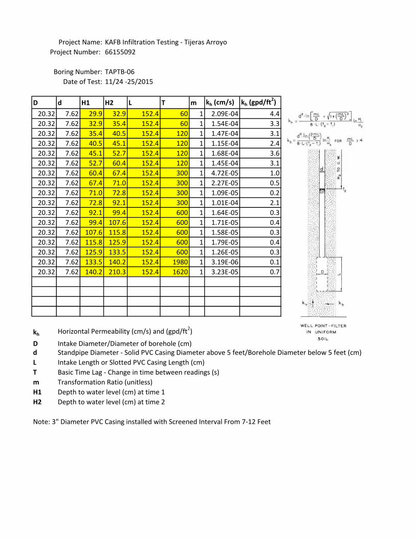
KAFB Infiltration Testing - Tijeras Arroyo
D d H1 H2 L T m kh (cm/s) kh (gpd/ft2)
20.32 7.62 29.9 32.9 152.4 60 1 2.09E-04 4.4
20.32 7.62 32.9 35.4 152.4 60 1 1.54E-04 3.3
20.32 7.62 35.4 40.5 152.4 120 1 1.47E-04 3.1
20.32 7.62 40.5 45.1 152.4 120 1 1.15E-04 2.4
20.32 7.62 45.1 52.7 152.4 120 1 1.68E-04 3.6
20.32 7.62 52.7 60.4 152.4 120 1 1.45E-04 3.1
20.32 7.62 60.4 67.4 152.4 300 1 4.72E-05 1.0
20.32 7.62 67.4 71.0 152.4 300 1 2.27E-05 0.5
20.32 7.62 71.0 72.8 152.4 300 1 1.09E-05 0.2
20.32 7.62 72.8 92.1 152.4 300 1 1.01E-04 2.1
20.32 7.62 92.1 99.4 152.4 600 1 1.64E-05 0.3
20.32 7.62 99.4 107.6 152.4 600 1 1.71E-05 0.4
20.32 7.62 107.6 115.8 152.4 600 1 1.58E-05 0.3
20.32 7.62 115.8 125.9 152.4 600 1 1.79E-05 0.4
20.32 7.62 125.9 133.5 152.4 600 1 1.26E-05 0.3
20.32 7.62 133.5 140.2 152.4 1980 1 3.19E-06 0.1
20.32 7.62 140.2 210.3 152.4 1620 1 3.23E-05 0.7
kh Horizontal Permeability (cm/s) and (gpd/ft2)
D Intake Diameter/Diameter of borehole (cm)d Standpipe Diameter - Solid PVC Casing Diameter above 5 feet/Borehole Diameter below 5 feet (cm)
L Intake Length or Slotted PVC Casing Length (cm)
T Basic Time Lag - Change in time between readings (s)
m Transformation Ratio (unitless)
H1 Depth to water level (cm) at time 1
H2 Depth to water level (cm) at time 2
Note: 3" Diameter PVC Casing installed with Screened Interval From 7-12 Feet
66155092
TAPTB-06
11/24 -25/2015
Project Name:
Project Number:
Boring Number:
Date of Test:

KAFB Infiltration Testing - Tijeras Arroyo
D d H1 H2 L T m kh (cm/s) kh (gpd/ft2)
20.32 20.32 -0.9 0.3 151.2 60 1
20.32 20.32 0.3 0.6 150.9 60 1 1.05E-02 223.8
20.32 20.32 0.6 1.5 150.0 120 1 7.04E-03 149.4
20.32 20.32 1.5 2.4 149.0 60 1 7.27E-03 154.3
20.32 20.32 2.4 3.7 147.8 60 1 6.31E-03 133.9
20.32 20.32 3.7 5.2 146.3 120 1 2.73E-03 57.9
20.32 20.32 5.2 6.7 144.8 120 1 2.03E-03 43.2
20.32 20.32 6.7 11.0 140.5 240 1 1.98E-03 42.0
20.32 20.32 11.0 14.0 137.5 300 1 7.99E-04 17.0
20.32 20.32 14.0 25.6 125.9 600 1 1.04E-03 22.0
20.32 20.32 25.6 33.8 117.7 1800 1 1.66E-04 3.5
20.32 20.32 33.8 42.4 109.1 1800 1 1.40E-04 3.0
20.32 20.32 42.4 49.7 101.8 3600 1 5.17E-05 1.1
20.32 20.32 49.7 57.0 94.5 3600 1 4.65E-05 1.0
20.32 20.32 57.0 62.5 89.0 3600 1 3.21E-05 0.7
20.32 20.32 62.5 101.5 50.0 3600 1 2.22E-04 4.7
kh Horizontal Permeability (cm/s) and (gpd/ft2)D Intake Diameter/Diameter of borehole (cm)
d Standpipe Diameter - Solid PVC Casing Diameter above 5 feet/Borehole Diameter below 5 feet (cm)
L Intake Length or Slotted PVC Casing Length (cm)
T Basic Time Lag - Change in time between readings (s)
m Transformation Ratio (unitless)
H1 Depth to water level (cm) at time 1
H2 Depth to water level (cm) at time 2
Note: 3" Diameter PVC Casing installed with Screened Interval From 0-5 Feet
66155092
TAPTB-06A
11/24-25/2015
Project Name:
Project Number:
Boring Number:
Date of Test: