Embed Size (px)
Citation preview

The South African Institute of Mining and Metallurgy International Symposium on Stability of Rock Slopes in Open Pit Mining and Civil Engineering Allan Haines
Page 133
GEOTECHNICAL DESIGN CONSIDERATIONS FOR THE PROPOSED
OYU TOLGOI OPEN PITS, SOUTHERN MONGOLIA
Allan Haines1, Peter Voulgaris2, Diane Walker1 and Ian de Bruyn1
1: SRK Consulting, Perth, 2: Ivanhoe Mines Mongolia Inc.
ABSTRACT
The Oyu Tolgoi porphyry gold and copper project is located in the south Gobi region of Mongolia. The Ivanhoe Mines project has the potential to become a long-life copper and gold producer that could rank among the largest in the world. There are five deposits which cover a strike length in excess of 6.5 km, from south to north they are named South Oyu, Southwest Oyu, Central Oyu, Hugo South and Hugo North. The first three, collectively known as the Southern Oyu deposits, are planned to be mined by open pits, whilst extraction of the deeper Hugo deposits is planned using block caving techniques. The pits will have diameters of approximately 1000m and a maximum depth of 550m. The geological environment consists of a sequence of porphyritic augite basalt, dacitic tuffs and sedimentary rocks that have been intruded by several generations of porphyritic quartz monzodiorite and numerous post mineralization dykes. Several major faults cut through the southern deposits juxtaposing the relative position of the stratigraphy. The geotechnical investigation for the Oyu Tolgoi Open Pits was conducted in three distinct phases of increasing complexity: scoping study; advanced scoping study and feasibility study. Each phase consisted of data collection, interpretation and analysis designed to progressively develop 3D geotechnical domaining for the empirical, structural and numerical evaluations. The development of the geotechnical design parameters for these green fields open pits posed many technical challenges, brought about by the conditions associated with a lithologically and structurally complex environment. The design work focused on the optimization of the pit geometry to conform to equipment selection and blasting characteristics. Limiting bench stack heights were derived from the influence of major structures. The overall slope angles in each pit sector were developed around the requirement for haulage ramps and geotechnical berms. This paper describes each of these aspects and the methodology used to address the integration of the geotechnical characteristics with the mining environment.

The South African Institute of Mining and Metallurgy International Symposium on Stability of Rock Slopes in Open Pit Mining and Civil Engineering Allan Haines
Page 134
1. INTRODUCTION The Oyu Tolgoi porphyry gold and copper project is located in the south Gobi region of Mongolia, approximately 600 km south of the capital Ulaanbaatar and 80km north of the Chinese-Mongolian border. The location of the project in Mongolia is shown in Figure 1. The project is 100% owned by Ivanhoe Mines Mongolia Inc. (IMMI), a wholly-owned subsidiary of Ivanhoe Mines Ltd., a public company listed in Canada and the USA. Details of the discovery of Oyu Tolgoi can be found in Perello et al, (2001), Forster et al. (2003) and Kirwin et al (2003). There are five deposits in the Oyu Tolgoi project which cover a strike length in excess of 6.5 km. From south to north they are named South Oyu, Southwest Oyu, Central Oyu, Hugo South and Hugo North. The first three deposits are planned to be mined by means of two open pits. The extraction of the deeper Hugo deposits is planned using two block cave mines. Ongoing step-out drilling on the Hugo North deposit has delineated further significant high-grade copper mineralization that could lead to construction of a third underground mine. The block caving projects are not discussed in this paper. As of May 2005 (AMEC-Ausenco Joint Venture, 2005) the Southern Oyu deposits have measured and indicated resources (0.3% Cu equivalent cut off) of 917 Mt at 0.50% Cu and 0.36 g/t Au. In addition there is an inferred resource of 78Mt at 0.37% Cu and 0.18 g/t Au. The Hugo deposits (0.6% Cu equivalent cut off) have indicated resources of 582 Mt at 1.89% Cu and 0.41 g/t Au and inferred resources of 1,072 Mt at 1.07% Cu and 0.21 g/t Au.
RUSSIA
CHINACHINA
Dalanzadgad
Khanbogd
Mandalgovi
Ulaanbaatar
Irkutsk
Beijing
Tianjin
Bayan Obo
Baotou
Jining
Sainshand
Datong
Chita
N
MONGOLIA
Hohot
OYU TOLGOI
0 400kmRailway
RUSSIA
Gulf of
Bohai
Figure 1: Project Location Map

The South African Institute of Mining and Metallurgy International Symposium on Stability of Rock Slopes in Open Pit Mining and Civil Engineering Allan Haines
Page 135
The relative ranking of the deposits from the highest to the lowest value is Hugo North, Southwest Oyu (including South Oyu), Hugo South, and Central Oyu. However, due to the long lead time required to develop and bring the first block cave to full production, mining will commence in Southwest Oyu. Nine open pit stages have been derived from optimization studies conducted on the Southern Oyu deposits. In the final geotechnical feasibility study only up to stage 7 was investigated. Stage 8 and 9 are the subject of on-going investigations. In the base case presented in the Integrated Development Plan (AMEC-Ausenco Joint Venture, 2005) it is planned that mining will commence at Southwest Oyu. This open pit will initially produce at 25.5 Mt/a (70,000 t/d). By year 7 the first two open pit stages will be complete and the open pit operation will cease in favor of the higher value ore from Hugo North. At full production Hugo North will produce at 30 Mt/a (85,000 t/d). The base case provides a mine life of 40 years and total production will exceed 16 Mt of copper and 360 t of gold. Before Hugo North reaches full production there is a point at which a decision can be made to expand the plant to 52.5 Mt/a (140,000 t/d) and continue mining the open pit for another four stages over a period of 20 years. The geotechnical investigations at the Southern Oyu deposits commenced, with the assistance of SRK Consulting, in July 2003. The geotechnical investigations have been conducted in three distinct phases of increasing complexity: scoping study (SRK Consulting 2003); advanced scoping study (SRK Consulting 2004) and feasibility study (SRK Consulting 2005). To help achieve this, a team of Mongolian geotechnical engineers were trained in hard rock geotechnical data collection, a field where there was no previous in country experience. Each study consisted of data collection, interpretation and analysis designed to progressively develop 3D geotechnical domaining for the empirical, structural and numerical evaluations. The feasibility level study was based on a geotechnical database of 110 drill holes, of which 16 were in the Central and 94 in the Southwest and South Oyu. Laboratory test results, geological, engineering geological and structural interpretations, hydrogeological studies and natural seismicity data were also used in the geotechnical analyses for the slope design. The development of the geotechnical design parameters for these green fields open pits posed many technical challenges, brought about by the conditions associated with a lithologically and structurally complex environment. The design work focused on the optimization of the pit geometry to conform to equipment selection and blasting characteristics. Limiting bench stack heights were derived from the influence of major structures. The overall slope angles in each pit sector were developed around the requirement for haulage ramps and geotechnical berms.

The South African Institute of Mining and Metallurgy International Symposium on Stability of Rock Slopes in Open Pit Mining and Civil Engineering Allan Haines
Page 136
A composite long section through the deposits is shown in Figure 2.
Figure 2: Longitudinal Section through the Deposits (after AMEC-Ausenco Joint
Venture, 2005) 2. GEOLOGICAL SETTING Due to uplift and erosion not all of the stratigraphy is present in the area of the Southern Oyu deposits. Two major stratigraphic sequences are recognized in the project area, the Devonian Alagbayan Formation and the Carboniferous Sainshandhudag Formation. The Devonian and Carboniferous sequences are separated by a regional unconformity that, in the Oyu Tolgoi area, is associated with a time gap of 10 Ma to 15 Ma. Only the units from the Devonian are found within the design pit limits. Carboniferous units are present immediately to the SE of South Oyu, however they will not be described here. A full description of the geology of Oyu Tolgoi can be found in the Integrated Development Plan (AMEC-Ausenco Joint Venture, 2005). A simplified geological map of the Southern Oyu area is shown in Figure 3. The lowest Devonian unit is over several hundred metres in thickness, comprising mafic flows of porphyritic augite basalt (VA) and volcanogenic sedimentary strata. These rocks are commonly strongly altered and host much of the contained copper in the Southern Oyu and Hugo deposits. Overlying the VA is a dacitic tuff (IGN) up to 200 m thick. The lower part of the IGN is usually overprinted by intense sericite and advanced argillic alteration. This unit is in turn overlain by a relatively thin dacitic block ash tuff (VBX) unit. A clastic sedimentary sequence overlies the VBX, comprising carbonaceous siltstone, fine brown sandstone and conglomerates intercalated with basaltic breccias, locally termed Unit L. This upper Devonian sequence forms a weakly-altered to unaltered, pre to syn-mineralization cover sequence to the Oyu Tolgoi deposits averaging around 300 m thick. Multiple phases of porphyritic quartz monzodiorite (QMD) and biotite granodiorite (BiGd) have intruded the Devonian sequence as batholithic bodies and wide dykes. They are

The South African Institute of Mining and Metallurgy International Symposium on Stability of Rock Slopes in Open Pit Mining and Civil Engineering Allan Haines
Page 137
genetically linked to the mineralization at Oyu Tolgoi. In many instances the QMD and BiGd are strongly to intensely altered.
Figure 3: Surface Geological Plan: Central, South and South-West Oyu Pit Areas
Mineralization in the Southern Oyu deposits is associated with quartz and sulphide vein stockworks with widths of several millimeters to several centimeters. Generally the grade increases with vein density, however chalcopyrite, subordinate pyrite and bornite are also present as disseminations and late fracture fillings within the host rocks. Late to post-mineral dykes are found throughout the project area and are present as narrow discontinuous dykes and sills that consist of basalt (Ba), rhyolite (RHY), hornblende biotite andesite (HbBiAnd) and dacite (DAC). Rhyolite dykes are the most abundant in the Southern Oyu deposits with typical widths of only a few metres, with the exception of a major, east-west rhyolite dyke that cuts through the middle of South Oyu which attains widths of up to a few tens of metres. The rhyolite dykes are steeply dipping with west to west-northwest strikes.

The South African Institute of Mining and Metallurgy International Symposium on Stability of Rock Slopes in Open Pit Mining and Civil Engineering Allan Haines
Page 138
A thin covering of gently-dipping to horizontal Cretaceous stratified clays and clay-rich gravels overlies the above formations, infilling paleochannels, and small fault-controlled basins. 3. STRUCTURAL SETTING The Southern Oyu deposits are flanked north and south by the Central and Solongo Faults respectively. Figure 3 shows the major structures in plan, while Figure 9 shows the fault intersections in the Southwest Pit wall. The Central fault is a west-northwest striking, moderately north dipping structure that lies between the Hugo South and Central Oyu deposits. It is not intersected in the Central Oyu open pit. The Solongo Fault is an east to east-northeast striking, subvertical structure that cuts across the Oyu Tolgoi property just south of the Southwest Oyu and South Oyu deposits. The Solongo Fault typically occurs as a strongly tectonized, foliated zone up to several tens of metres wide. Rhyolite dykes commonly intrude the fault zone, and themselves have tectonically brecciated margins. The Central deposit occupies a structurally intact block within which no significant internal fault disruption has been identified. The most prominent faults at Central Oyu lie along the eastern side of the deposit, and separate the mineralized QMD, VA and IGN from the non-mineralized Devonian sediments to the east. Two major fault surfaces have been identified from drill hole data. In the northeastern deposit area, the main structure is a north striking, moderately east-dipping fault. This fault cuts a northeast striking, southeast dipping fault that locally forms the eastern limit to mineralization. Both of these faults occur as wide, tectonized zones within the base of the Devonian sediments. The Southwest Oyu deposit lies between two major northeast-striking faults, the West Bounding Fault and the East Bounding Fault as shown in cross section in Figure 4. Both faults are well constrained by drill hole intersections. The bounding faults form zones from a few meters to a few tens of metres in width consisting of foliated cataclasite, gouge/breccia, and mylonitic bands. Correlation of drill hole fault intersections constrains an average fault orientation of 80° towards 310° for both structures. The West Bounding Fault can be traced northward as far as the southern part of the Central Oyu deposit, but cannot be recognized in drill holes that cross its trace in the southern part of Southwest Oyu. The West Bounding Fault is commonly intruded by hornblende-biotite andesite dykes, whereas rhyolite dykes are more abundant along the East Bounding Fault. Movement on the East Bounding and the east-northeast striking South faults has juxtaposed younger strata within this fault block against older strata on the adjacent blocks containing the Southwest and South deposits. This rectangular shaped fault bound block is termed the Wedge Deposit. Within the Wedge Deposit fault disruption is common along the contact between the IGN and the overlying sedimentary strata. This fault is called the Contact Fault. Second order fault structures are frequently observed in drill core, with true widths of 10 – 20 cm. They are most abundant in the VA host rocks. Measurements of minor faults from oriented drill core show a wide range of orientations with weak or nonexistent preferred

The South African Institute of Mining and Metallurgy International Symposium on Stability of Rock Slopes in Open Pit Mining and Civil Engineering Allan Haines
Page 139
orientation (Lewis, 2004). However, a subset of the data for drill hole fault intersections in the core of Southwest Oyu shows a moderate preferred north-south strike, steeply west dipping fault surfaces (Lewis, 2004). Due to the relative large drill hole spacing no spatial interpretation was undertaken on these secondary structures.
Figure 4: Cross Section through the Southwest – South Oyu Pit Area
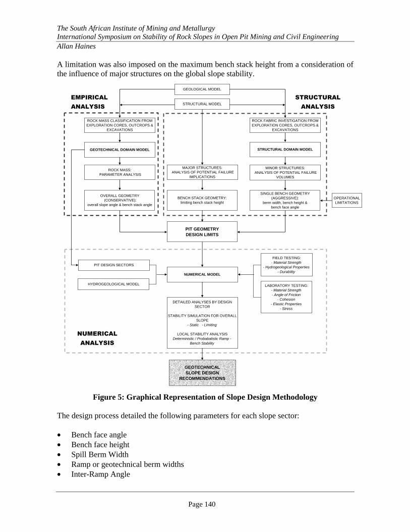
4. ANALYSIS AND DESIGN PROCESS The methodology adopted for the evaluation of the slope design parameters was to establish an initial design envelope using empirically (lower bound, conservative) and structurally (upper bound, optimistic) derived indicative slope design parameters. These two approaches provided a reliable starting point and determined the limits within which the final stage numerical modelling could proceed. The process is graphically displayed in Figure 5. The empirical analysis provided initial estimates of Indicative Bench Stack Angles (IBSA) and the Indicative Overall Slope Angles (IOSA). This was supplemented with comparative bench stack angles from the structural analysis in order to obtain a first pass slope design that was subsequently tested in the numerical modeling. The initial structural evaluation of the rock mass fabric determined the Spill Berm Width (SBW) and Bench Face Angle for the various design sectors.
The South African Institute of Mining and Metallurgy International Symposium on Stability of Rock Slopes in Open Pit Mining and Civil Engineering Allan Haines
Page 140
A limitation was also imposed on the maximum bench stack height from a consideration of the influence of major structures on the global slope stability.
Figure 5: Graphical Representation of Slope Design Methodology
The design process detailed the following parameters for each slope sector: • Bench face angle • Bench face height • Spill Berm Width • Ramp or geotechnical berm widths • Inter-Ramp Angle
ROCK MASS CLASSIFICATION FROM EXPLORATION CORES, OUTCROPS &
EXCAVATIONS
DETAILED ANALYSES BY DESIGN SECTOR
STABILITY SIMULATION FOR OVERALL SLOPE
- Static - Limiting
LOCAL STABILITY ANALYSISDeterministic / Probabalistic Ramp -
Bench Stability
GEOTECHNICAL SLOPE DESIGN
RECOMMENDATIONS
ROCK FABRIC INVESTIGATION FROM EXPLORATION CORES, OUTCROPS &
EXCAVATIONS
GEOLOGICAL MODEL
STRUCTURAL MODEL
MINOR STRUCTURES: ANALYSIS OF POTENTIAL FAILURE
VOLUMES
STRUCTURAL DOMAIN MODEL
SINGLE BENCH GEOMETRY (AGGRESSIVE):
berm width, bench height & bench face angle
OPERATIONAL LIMITATIONS
MAJOR STRUCTURES: ANALYSIS OF POTENTIAL FAILURE
IMPLICATIONS
OVERALL GEOMETRY (CONSERVATIVE):
overall slope angle & bench stack angle
GEOTECHNICAL DOMAIN MODEL
ROCK MASS: PARAMETER ANALYSIS
BENCH STACK GEOMETRY:limiting bench stack height
PIT GEOMETRY DESIGN LIMITS
PIT DESIGN SECTORS
NUMERICAL MODEL
HYDROGEOLOGICAL MODEL
EMPIRICAL
ANALYSIS
STRUCTURAL
ANALYSIS
NUMERICAL
ANALYSIS
LABORATORY TESTING:- Material Strength- Angle of Friction
- Cohesion- Elastic Properties
- Stress
FIELD TESTING:- Material Strength
- Hydrogeological Properties- Durability

The South African Institute of Mining and Metallurgy International Symposium on Stability of Rock Slopes in Open Pit Mining and Civil Engineering Allan Haines
Page 141
• Limiting bench stack height and angle • Overall slope angle constraints The slope terminology that is referred to in the following sections is defined in Figure 6.
OSA
Overall Slope Height
Geotechnical Berm or Ramp
bench stack
bench stack
Pit Floor Level
SBW
bench height
BSA
IRA
bench face angle
Figure 6: Slope Geometry Terminology Where: Bench Stack Angle (crest to toe) BSA
Indicative Bench Stack Angle (crest to toe) IBSA Overall Slope Angle OSA Indicative Overall Slope Angle IOSA Inter Ramp Angle (toe to toe) IRA Spill Berm Width SBW
5. GEOTECHNICAL DOMAINS In order to assist in the optimization of the designs the pits were divided into 12 sectors which correspond closely to zones of differing rock mass conditions. These were identified according to the distribution of lithologies, the structural fabric of the rock mass, the positions of major structures, hydrogeological properties and the orientations of the walls of the pits. The location of the geotechnically logged drill holes with respect to the 12 geotechnical sectors is shown in Figure 7. More specifically, the behaviour of the rock mass in terms of its engineering properties varied according to: • The structural characteristics of the rock mass, which include:
The orientations of the principal structures and dominant structural sets The persistence and spacing of the discontinuities within the structural sets The nature of the discontinuity surfaces (infill and roughness)
• The strength of the intact rock (which is dependent on rock type, weathering and alteration)
• The hydrogeological properties of the rock-mass, and the presence of groundwater.

The South African Institute of Mining and Metallurgy International Symposium on Stability of Rock Slopes in Open Pit Mining and Civil Engineering Allan Haines
Page 142
The ultimate performance of the pit walls will be controlled by these factors.
Figure 7: Positions of the Geotechnically Logged Drill Holes with respect to the
Geotechnical Design Sectors Figure 7 also illustrates the ten cross sections used for the numerical modelling. In addition to the 12 geotechnical sectors, the rock mass was sub-divided vertically into four separate intervals. These were based on variations in the rock mass and

The South African Institute of Mining and Metallurgy International Symposium on Stability of Rock Slopes in Open Pit Mining and Civil Engineering Allan Haines
Page 143
hydrogeological conditions with depth, resulting in a total of 48 geotechnical domains across the two pits. The vertical intervals are as follows: • Interval 1: 60m (1150 – 1090m RL) including the weathered zone • Interval 2: 90m (1090 – 1000m RL) the height of one bench stack, immediately below
the weathered zone • Interval 3: 180m (1000 – 820m RL) the height of two bench stacks • Interval 4: >180m (below 820m RL) final interval including all other bench stacks to
the base of the respective pits. The Rock Mass Rating (RMR) classification system according to Laubscher (1990) and as applied by SRK, was used for the evaluation of spatial domaining of the drill hole database. The RMR was also used in the assessment of the rock mass strength parameters used for the numerical analysis. Average RMR values for the sectors and vertical interval are given in Table 1.
CENTRAL OYU SOUTHWEST OYU
Vertical Interval
Nor
th
Eas
t
Wes
t
Sout
h
NW
Mid
dle
Wed
ge
SE
S SW
SWa
Solo
ngo
Average RMR 44 44 45 45 47 46 44 42 39 45 42 43
1150 – 1090m RL 19 40 40 33 40 39 43 41 41 38 36 37
1090 – 1000m RL 42 42 38 45 46 46 42 42 39 44 47 47
1000 – 820m RL 45 45 46 43 47 46 44 42 39 45 43 39
below 820m RL 48 52 52 50 48 48 46 41 40 46 35 -
Table 1: Average RMR for each Sector and by Vertical Interval 6. EMPIRICAL EVALUATION The empirical evaluation is based on the mining adjusted RMR, the Mining Rock Mass Rating (MRMR) Classification System (Laubscher, 1990). The MRMR process is an extremely useful and robust method of utilizing all of the relevant rock mass parameters to assist with mine design. It has been used in open pit mining from initial scoping studies, through to full mine production. This in-situ RMR is adjusted to take account of the expected mining environment, namely the influence of weathering, structural orientation, induced stresses and blasting. The adjustments to the in-situ RMR are introduced in recognition of the type of excavation proposed and the time dependent behaviour of the rock mass.

The South African Institute of Mining and Metallurgy International Symposium on Stability of Rock Slopes in Open Pit Mining and Civil Engineering Allan Haines
Page 144
The possible percentage adjustments are as follows: • Weathering 30 to 100% • Orientation 63 to 100% • Induced Stresses 60 to 120% • Blasting 80 to 100% Although the percentages are empirical, the principle has proved sound, and as such it forces the designer to allow for these important factors during the evaluation process. In effect, the anticipated deterioration of the rock mass, once exposed in the mine environment, is provided for in these adjustments. The Haines and Terbrugge (1991) methodology is empirically derived, and relates the MRMR through the bench stack height to derive a bench stack angle. Experience over the last 14 years has proven that the use of this methodology is appropriate. The Indicative Bench Stack Angle (IBSA) for each sector is selected from Figure 8.
Figure 8: MRMR versus Bench Stack Angle Relationship
The MRMR values, as derived for the range of design materials, are used to determine an Indicative Overall Slope Angle (IOSA) and an Indicative Bench Stack Angle (IBSA). The bench stack angles were determined for a FoS (Factor of Safety) of 1.35, which is interpolated between the values for 1.20 and 1.50 in Figure 8.

The South African Institute of Mining and Metallurgy International Symposium on Stability of Rock Slopes in Open Pit Mining and Civil Engineering Allan Haines
Page 145
Using a lower FoS would have resulted in a higher IBSA value, increased by approximately 5°, which would have narrowed the gap between the empirically and structurally derived indicative values. In this empirical evaluation the FoS is not related to any specific failure mechanism but to a generic failure of a bench stack. Table 2 shows the average RMR, MRMR, IOSA and IBSA for each vertical interval in each domain. Average RMR values are similar across the different domains, showing slight improvement with depth in places. The North, East and Wedge Domains show slightly lower average values due to the higher percentage siltstone and ignimbrite in these domains. The South (SW), South East and Solongo Domains show lower average RMR values, associated with the higher degree of faulting in these areas of the pits. 7. STRUCTURAL EVALUATION The structural evaluation was carried out in two parts; a major structure evaluation and minor structural analysis. The major structure evaluation was undertaken to identify large scale instability, and the minor structural analysis was carried out to determine the optimum bench and spill berm geometries. 7.1 Major Structure Evaluation The sub-vertical inclination of the major structures is generally favourable for the slope orientations. However, the orientation and nature of the major structures has a definite influence on the determination of the limiting bench stack height. Of concern was the potential for large wedges, formed from the combination of the major known faults and minor faulting and shearing, which can influence the stability of inter-ramp slopes where stacks of benches are at risk. The influence of the major structures on the stability of the pit walls was assessed for each design domain. IMMI wireframe models of the major structures and the structural analysis of P. Lewis (2004, 2005) were used as the basis for the interpretation of the large-scale structural geotechnical risk. This included the intersection of secondary structures and large regional structures. The zones of greatest risk for the south west pit are illustrated in Figure 9.


The South African Institute of Mining and Metallurgy International Symposium on Stability of Rock Slopes in Open Pit Mining and Civil Engineering Allan Haines
Page 147
Figure 9: Southwest Pit Zones of Adverse Geological Structural Geometry
(faults are shown as intersections with the pit wall) Faults and fault zones were present in all rock types logged (except quartz veins). The amount of faulting in each rock type varied from 4% to 14%. The percent of faulted core in the two most common rock types, QMD and VA was 7.4% and 5.8% respectively. The siltstone contained the highest percentage of faults and the dacite the lowest. The percentage of intact (healed) faults was highly variable, although in most rock types more than 80% of the faults were open. In the IGN all faults/ fault zones were open, whereas in the HBX, 56% of the faults/ fault zones were intact. The majority of faults in the weathered intervals were open structures.

The South African Institute of Mining and Metallurgy International Symposium on Stability of Rock Slopes in Open Pit Mining and Civil Engineering Allan Haines
Page 148
The limiting bench stack height is a function of the frequency and attitude of the major structures relative to the pit shell. For any bench stack it is recommended that only one major structure has the potential to influence the stability of that stack. A limit to the stack height must be imposed where it is assessed that more than one major structure, or in combination with minor or secondary structures, can adversely influence the bench stack stability. For the Southwest and Central pits it has been assessed that a limiting bench stack height of 90m be implemented. The implication of this is that for every 90m vertically the bench stacks must be separated with either a ramp or a geotechnical safety berm. The geotechnical safety berm should be between approximately two to three times the corresponding spill berm width between individual benches for that sector. A geotechnical safety berm will be required to limit the impact of those oversize wedges that may fail. Correspondingly, a limiting stack height of 60m was recommended for the weathered material. The impact of major and second order fault related structures was also incorporated into the derivation of the RMR and MRMR parameters. 7.2 Minor Structure Analysis Dominant discontinuity sets were analysed from the oriented drill holes for each major rock type. These were combined to obtain rock mass fabric plots for each of the design sectors and vertical intervals. With the bench height set at 15 m by IMMI mine planners the analysis provided recommendations for the optimum bench face (batter) angle and optimum spill berm widths (SBW). For each domain subdivision, the possibility of wedge failure development was assessed for a range of discontinuity friction angles determined from laboratory testing results (25º, 30º and 35º) and bench face angles of 65º and 75º for vertical interval 1 (including the weathered zone) and 75º and 85º for all vertical intervals below this. Where formation of a potential failure wedge was identified, the data including the orientations of the intersecting discontinuities, the wall orientation, and bench face angles were analysed using Rocscience’s SWEDGE software in order to calculate the FoS and the volume of the wedge. The volumes of wedge material produced upon failure are dependent on the geometry of the individual wedges, the persistence of the wedge-forming discontinuities, the height and width of the bench and the bench face angle. The SBW was calculated using the equation:
5.13 ×= VolumeSBW The SBW varied between 5m and 9m depending on the pit sector and bench face angle.

The South African Institute of Mining and Metallurgy International Symposium on Stability of Rock Slopes in Open Pit Mining and Civil Engineering Allan Haines
Page 149
A 65° bench face angle for the weathered rock and 75° for the unweathered rock were recommended. These are considered appropriate for the rock mass in consideration of the geotechnical conditions. Table 3 provides a comparison of the bench stack angles (at their limiting heights) as they were derived from both the empirical and structural evaluations. The range between the empirical and structural values is between approximately 10° and 12°. The indicated angle in Table 3 was the starting point for the numerical modeling. Also shown are the bench stack angles that came from the previous years advanced scoping study. 8. NUMERICAL EVALUATION The empirical and structural results are normally considered the respective lower and upper bounds for the starting point of numerical modelling. For this numerical modelling evaluation an indicated value was used as the starting point. This was selected at a point one third up from the lower bound empirically derived value for bench stack angle at the limiting height. Numerical analyses of the proposed pit slopes were carried out using FLAC (ITASCA, 2002). The models were developed to study the expected macroscopic slope behaviour using the estimated rock mass properties. The models were thus concerned with large-scale slope behaviour, susceptibility to stress related deformation and sensitivity to pore pressure distributions. This modelling complemented the empirical and structural analyses and studies the sensitivity of the slope stability to the resulting range of indicated bench stack angles. Rock mass strength parameters were estimated using the Hoek & Brown Failure Criterion (Hoek et al., 2002) drawing on the RMR and laboratory test results as input. The results of the hydrogeological field testing (AQUATERRA, 2004) were also incorporated into the numerical modelling as well as the records of natural seismicity of the area. A total of ten cross sections through the two pits were selected for FLAC analysis. These are shown in Figure 7. The sections were selected to incorporate the nature of the geotechnical sectors and to capture the detail of the pit geometry. The modelling approach for each section was to analyse the slope stability for the proposed starting condition. This used an inferred angle between the calculated BSA from the structural and the empirical analyses.


The South African Institute of Mining and Metallurgy International Symposium on Stability of Rock Slopes in Open Pit Mining and Civil Engineering Allan Haines
Page 151
The FLAC models enable larger scale instability mechanisms to be considered for a critical failure surface through the rock mass and include the destabilising effect of the groundwater profile. The slope angle was changed incrementally until the calculated safety factor approached 1.35. Increased slope drainage of up to 200m was included in the stability models to consider the potential to maximise the slope angle. The drainage was assumed to result in the lateral push back of the groundwater profile by the installation of horizontal drains in the pit slopes. From the numerical modelling, the location of potential critical failure surfaces defined a zone of influence behind the crest that could potentially be affected by slope instability if the design external stresses or piezometric conditions are not achieved or maintained. The extent of this zone is typically in the range of 150m to 300m behind the pit crest. Some sectors will thus require induced drainage in the form of sub-horizontal drain holes, ranging from 100m to 200m in length, to augment the pit floor sump pumping. The drilling of 25-30m long drain holes to locally dewater sections of pit wall may be required. The numerical seismicity analysis was based on an earthquake with a return period of 475 years (BAZARIIN, B., 2005). This type of earthquake has a probability of occurrence of 10% in 50 years. The results indicate that permanent displacements of the pit slopes can be expected, and that these might generate cracks and minor wedge failures, but no large scale failure in the pit wall slopes is anticipated. Sectors 8 and 9 have the largest permanent displacements, which can reach up to 0.45m. It is recommended that pit infrastructure such as crushers, conveyors, etc are not placed in these sectors. The permanent displacements experienced by the rest of the area are equal or less than 0.15m. The influence of the in-situ stress regime was also considered in the design process (WASM, 2004). 9. SLOPE DESIGN PARAMETERS The final detailed slope design recommendations required a number of iterations incorporating feedback from the IMMI mine planning team. The Bench Stack Angles were adjusted to have a smooth transition of berm width between one sector and another. The slope angle recommendations are summarised in Figure 10 for each geotechnical sector and vertical interval. The bench stack angles recommended at feasibility study level are 5° to 6° steeper than those that were provided in the advanced scoping study. This is partly due to the enhanced structural interpretation which provided a higher upper limit. The numerical modelling has returned values which are within the range of the empirical and structural evaluations. The resulting slope design recommendations are therefore considered appropriate.

The South African Institute of Mining and Metallurgy International Symposium on Stability of Rock Slopes in Open Pit Mining and Civil Engineering Allan Haines
Page 152
Figure 10: Final Slope Angle Recommendations
The results of the numerical modelling, the last stage in the derivation of the slope design parameters, has returned bench stack angles (BSA’s) which fall into the range between the lower Empirical/Indicted boundary and the upper Structural/Indicated boundary. For example, the uppermost vertical interval has BSA’s in the 45°-49° range while the lowermost vertical interval has BSA’s in the 49°-57° range. Both correspond to the expected range as derived from the empirical and structural evaluations. With the inclusion of ramps and geotechnical berms the recommended Limiting Overall Slope Angle (LOSA) falls into the 41°-44° range.

The South African Institute of Mining and Metallurgy International Symposium on Stability of Rock Slopes in Open Pit Mining and Civil Engineering Allan Haines
Page 153
10. DISCUSSION AND OPERATIONAL CONSIDERATIONS It is important to note that design work should continue during pit operations. The design recommendations and predictions from a feasibility study, which are based on an interpretation of data and expected conditions, must be monitored and validated during operations from the actual encountered conditions. Engineering judgment has been applied in the determination of appropriate geotechnical parameters. It is thus important that additional information is collected and evaluated during the early stages of mining. In particular, these efforts should be focused on a better understanding of the groundwater conditions on site, and also on obtaining further rock mass classification and major structural and discontinuity information through the pit wall mapping. With the adoption of a rigorous slope management programme in the early stages of pit formation it should be possible to further reduce the geotechnical risk. An appropriate slope management plan should make provision for: • Monitoring of the groundwater conditions (installation of piezometers); • Installation and monitoring of survey prisms for slope deformation; • Use of slope radar to monitor slope movements; • Monitoring and control of pit limit blasting; • Monitoring of cracks by means of wire extensometers; • Surface water control and monitoring; • Control of erosion, and; • Routine geotechnical and structural mapping and reduction/interpretation of the data. Care must also be exercised in the blasting of the bench faces. Some sectors will require induced drainage in the form of sub-horizontal drain holes, ranging from 100m to 200m in length, to augment the pit floor sump pumping. 11. ACKNOWLEDGEMENTS The authors would like to acknowledge the support and assistance given by Ivanhoe Mines Mongolia Inc. in the development of this study and approval to publish this paper. In particular, the assistance of Jess Harding is appreciated. 12. REFERENCES AMEC-AUSENCO JOINT VENTURE (AAJV), Oyu Tolgoi Project Integrated Development Plan. 2005, (in 3 volumes). AQUATERRA CONSULTING PTY LTD, Feasibility Study, Oyu Tolgoi Dewatering Investigation: Open Pit and Block Cave Mining. Report prepared for Ivanhoe Mines Mongolia Inc., October 2004.

The South African Institute of Mining and Metallurgy International Symposium on Stability of Rock Slopes in Open Pit Mining and Civil Engineering Allan Haines
Page 154
BAZARIIN, B. Seismic Hazard Assessment of Oyu Tolgoi Site, Final Report. 2005. FORSTER, C.N., KIRWIN, D.J., KAVELIERIS, I., CRANE, D., ORSSICH, C., PANTHER, C., GARAMJAV, D., MUNKHBAT, T.O. and NIISLELKHUU, G., Exploration, geology and mineralisation of the Oyu Tolgoi gold-copper porphyry deposit, south Gobi, Mongolia. Baker,T., Cleverly,J., and Fu, B., (eds), Magmas, Fluids and Porphyry-Epithermal Deposits Symposium. James Cook University Economic Geology Research Unit Contribution 61, 2003, pp.47-59. HAINES, A. and TERBRUGGE, P. J. Preliminary estimation of rock slope stability using rock mass classification systems. Proc. 7th Int. Conf. Int. Soc. Roc Mech., Aachen, Germany, Volume 2, 1991, Balkema, pp 887 - 892. HOEK, E., CARRANZA-TORRES, C.T. and CORKUM, B., Hoek-Brown failure criterion. Proc. North American Rock Mechanics Society meeting in Toronto, July 2002. KIRWIN, D.J., FORSTER, C.N., CRANE, D. and GARAMJAV, D., The discovery of the Oyu Tolgoi porphyry copper-gold deposit, south Gobi, Mongolia. New Generation Gold AMF, 2003, pp 130-138. LAUBSCHER, D.H. A geomechanics classification system for the rating of rock mass in mine design. Jl S. Afr. Inst. Min. Metall., Vol 90, No 10, 1990, pp257-273. LEWIS, P. Structural Analysis, Southwest Oyu Deposit, Oyu Tolgoi Project, Mongolia. Lewis Geosciences Ltd. Internal Report to Ivanhoe Mines Mongolia. 2004. PERELLO, J., COX, D., GARAMJAV, D., SANDORJ, S., DAIKOV, S., SCHISSEL, D., MUNKHBAT, T. and OYUN, G., Oyu Tolgoi, Mongolia: Siluro-Devonian porphyry Cu-Au-(Mo) and high sulphidation Cu mineralization with a Cretaceous chalcocite blanket, Economic Geology, Volume 96, 2001, pp. 1407-1428. SRK CONSULTING. Scoping Study Report on the Oyu Tolgoi Project., Report prepared for Ivanhoe Mines Mongolia Inc., August 2003 SRK CONSULTING. Advanced Scoping Study Report on the Geotechnical Evaluation of the South West and Central Open Pits., Report prepared for Ivanhoe Mines Mongolia Inc., July 2004 SRK CONSULTING. Feasibility Study Report on the Geotechnical Evaluation of the South West and Central Open Pits., Report prepared for Ivanhoe Mines Mongolia Inc., April 2005 WASM. Stress measurements from oriented core using the Acoustic Emission method: Ivanhoe Mines Mongolia, Oyu Tolgoi Project. Villaescusa E., Li J. and Windsor C. (eds), 2004.