Embed Size (px)
Citation preview
GEOTECHNICAL AND PAVEMENT DESIGN REPORT Country Club Road Infrastructure Improvement Project Lake Oswego, Oregon For Murraysmith July 3, 2018 GeoDesign Project: LakeOswego-37-01
9450 SW Commerce Circle, Suite 300 l Wilsonville, OR 97070 l 503.968.8787 www.geodesigninc.com
July 3, 2018 Murraysmith 888 SW 5th Avenue, Suite #1170 Portland, OR 97204 Attention: Adam Crafts, P.E.
Geotechnical and Pavement Design Report Country Club Road Infrastructure Improvement Project
Lake Oswego, Oregon GeoDesign Project: LakeOswego-37-01
GeoDesign, Inc. is pleased to submit this geotechnical and pavement design report for the proposed Country Club Road Infrastructure Improvement Project in Lake Oswego, Oregon. We appreciate the opportunity to be of service Murraysmith and the City of Lake Oswego. Please contact us if you have questions regarding this report. Sincerely, GeoDesign, Inc. Krey D. Younger, P.E., G.E. George Saunders, P.E., G.E. Senior Associate Engineer Principal Engineer KDY:GPS:kt:sn
Attachments
One copy submitted (via e-mail only)
Document ID: LakeOswego-37-01-070318-geor.docx
© 2018 GeoDesign, Inc. All rights reserved.

LakeOswego-37-01:070318
TABLE OF CONTENTS PAGE NO. 1.0 INTRODUCTION 1 2.0 PURPOSE AND SCOPE 1 3.0 SITE CONDITIONS 2 3.1 Existing Surface Conditions 2 3.2 Subsurface Conditions 2 3.3 Groundwater 4 4.0 PAVEMENT DESIGN VALUES 4 4.1 ESAL Calculations 4 4.2 Existing AC/PCC Structural Capacity Calculations 5 4.3 Other Design Parameters 5 5.0 CONSTRUCTION RECOMMENDATIONS 6 5.1 Site Preparation 6 5.2 Excavation 8 5.3 Pavement Structure Recommendations 9 5.4 Materials 11 6.0 OBSERVATION OF CONSTRUCTION 13 7.0 LIMITATIONS 13 FIGURES Vicinity Map Figure 1 Site Plan Figure 2 APPENDICES Appendix A Field Exploration Data A-1 Laboratory Testing A-2 Exploration Key Table A-1 Soil Classification System Table A-2 Boring Logs Figures A-1 - A-13 Core Location and Core Photographs Figures A-14 - A-17 Atterberg Limits Test Results Figure A-18 Summary of Laboratory Test Data Figure A-19 Appendix B Prior Explorations B-1 Boring Logs Appendix C FWD Data C-1 FWD Results - AC over PCC Analysis Table C-1 ACRONYMS AND ABBREVIATIONS

1 LakeOswego-37-01:070318
1.0 INTRODUCTION GeoDesign, Inc. is pleased to submit this geotechnical and pavement design report for the proposed Country Club Road Infrastructure Improvement Project in Lake Oswego, Oregon. We understand current improvement plans include various utility and pavement improvements. Proposed utility improvements include trenching up to 25 feet BGS within Country Club Road between A Avenue and Iron Mountain Boulevard and directional drilling to the properties at 471 Country Club Court and 465 Country Club Road. Our pavement design is based on the information from our previous report1 in conjunction with recent design information from Murraysmith, the City of Lake Oswego (City), and our additional field investigation The site relative to surrounding features is shown on Figure 1. Our exploration locations are shown on Figure 2. Acronyms and abbreviations used herein are defined at the end of this document. 2.0 PURPOSE AND SCOPE The project includes testing and explorations to provide geotechnical design elements as well as pavement construction and rehabilitation recommendations. Our specific scope of services was as follows: Reviewed preliminary information provided by the City. Reviewed our previous pavement design report. Completed traffic control plans for the proposed field work and obtained lane closure
permits. Provided traffic control during the explorations. Explored subsurface conditions by drilling seven borings to depths of up to 26.5 feet BGS in
the existing pavement within pavement and trenching areas. Explored subsurface conditions by advancing seven hand-augered borings to depths of up to
5.5 feet BGS in the directional drilling areas. Maintained a detailed log of the explorations, and collected samples of the pavement, base,
and soil materials encountered. Completed laboratory tests on select samples collected from the explorations. Conducted
moisture content determinations, wash sieve analysis, and Atterberg limits testing. Calculated pavement rehabilitation options for AC over PCC pavement. Evaluated reconstruction options based on our review of the previous report and new traffic
data provided by the City. Provided pavement structural designs for new pavement. Provided recommendations for pavement rehabilitation for the AC over PCC pavement. Provided recommendations for new pavement construction. Provided recommendations for materials and construction. Provided a draft report summarizing our recommendations. Provided this final report following comments and recommendations from the design team.
1 GeoDesign, Inc. Pavement Design Report; Pavement Design on Various Streets within the City of Lake Oswego; A Avenue, Boones Ferry Road, and Country Club Road; Lake Oswego, Oregon, dated August 17, 2010. GeoDesign Project: LakeOswego-22-01

2 LakeOswego-37-01:070318
3.0 SITE CONDITIONS This road section runs roughly northwest to southeast, with directions referred to as westbound and eastbound in this report. There are two lanes in each direction. Pavement surfacing is AC, and there are bike lanes with some intermittent sidewalk. Road grades are relatively flat. In addition, based on information provided by the City, we understand that there is an older PCC pavement section below the AC in the center of the road, beneath both left lanes. The exact border of the PCC pavement is unknown. 3.1 EXISTING SURFACE CONDITIONS In general, the existing pavement is in poor to fair condition. Pavement distress predominately includes moderate cracking throughout. 3.2 SUBSURFACE CONDITIONS Our explorations included drilled borings in the existing pavement and hand-augered borings in residential landscaped areas. Four borings (B-1 through B-4) were completed on April 11, 2017, three borings (B-5 through B-7) were completed on August 14, 2017, and seven borings (HA-1 through HA-7) were completed on August 17, 2017. In addition, we reviewed the previous pavement explorations, which include five additional pavement cores (C-3, C-4, C-7, C-8, and C-11) completed on this road section in May 2010. The borings were extended into the subgrade to depths up to 26.5 feet BGS. The approximate exploration locations are shown on Figure 2. The exploration logs and a detailed description of the 2017 field explorations are presented in Appendix A, and the exploration logs of the 2010 field explorations are presented in Appendix B. 3.2.1 Pavement Materials A summary of the pavement thicknesses and pavement cracking is presented in Tables 1 and 2. Table 1 outlines our pavement explorations from April 11, 2017 and August 14, 2017. Table 2 outlines the pavement explorations from May 2010. In general, the pavement in the outer (right) lanes is AC over aggregate base and the pavement in the inside (left) lanes is AC over PCC. Photographs of pavement cores and testing locations for B-1 through B-4 are presented in Appendix A.

3 LakeOswego-37-01:070318
Table 1. Existing Pavement Thickness, April 2017
Boring Location Lane and Location
Pavement Thickness (inches)
Crack Location(inches BGS)
AC PCC Base
B-1 Left Lane EB BWT 6.3 8.5 NP None
B-2 Right Lane WB BWT 6.8 NP 7.2 0 to 1.7
B-3 Left Lane WB BWT 3.5 7.3 NP None
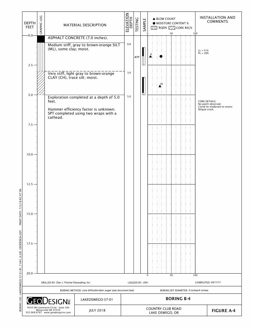
B-4 Right Lane EB OWT 7.0 NP NP 0 to 7.0
B-5 Country Club Court East side 3.5 NP 1.5 None
B-6 Right Lane WB OWT 6.0 NP 10.0 None
B-7 Right Lane WB OWT 6.0 NP 12.0 None
Table 2. Existing Pavement Thicknesses, May 2010
Boring Location Lane and Location
Pavement Thickness (inches)
Crack Location (inches BGS)
AC PCC Base
C-3 Right Lane EB OWT 8.0 NA 6.0 0 to 3.0
C-4 Right Lane EB OWT 6.5 NA 14.5 0 to 1.8
C-7 Left Lane EB BWT 6.0 6.0 NA1 None
C-8 Right Lane WB OWT 6.8 NA 4.2 0 to 6.8
C-11 Left Lane WB BWT 5.8 6.0 NA1 0 to 11.8
1. Aggregate base thickness was not measured or boring was terminated in aggregate base due to utility conflict.
3.2.2 Subgrade Materials The subgrade beneath the pavement varies from soft to very stiff silt or clay (B-1, B-3, B-4, B-5, B-7, C-3, C-4, C-7, C-8, C-11) and medium dense to very dense gravel (B-2 and B-6). Moisture content of the subgrade at the time of testing varied from 21 to 30 percent. In addition, Atterberg limits testing at B-3, B-4, B-7, C-3, C-11, and C-12 indicates plasticity index from 12 and 84 percent. Decomposed basalt was encountered below the pavement materials (B-5, B-6, and B-7) or underlying the above-described subgrade soils (we note that the gravel at B-1 and B-2 may also be decomposed basalt). The depth to the decomposed basalt varies considerably and was encountered at increasing depth south to north. In addition, the composition of the decomposed basalt varies considerably. At B-3, B-5, and B-7 the subsurface conditions consist of soft to very stiff clay or silt to depths of 15 to 21 feet BGS underlain by medium dense sand (B-3) or dense to very dense gravel (B-5 and B-7) to the depth of explorations. At B-6 we encountered medium dense to very dense gravel to 22.0 feet BGS underlain by dense sand to the depth of the exploration. In addition, we encountered areas of

4 LakeOswego-37-01:070318
very hard drilling, suggesting boulders at 4.0 and 12.0 feet BGS in B-6. Drill cuttings from all explorations were indicative of decomposed basalt. Additional details are provided on the exploration logs presented in Appendix A. We note that the April 2017 explorations (B-1 through B-4) were completed using a solid-stem auger and a trailer-mounted drilling rig with a limited downforce capacity (and encountered refusal conditions at shallow depths) while the August 2017 explorations (B-5 through B-7) were completed with a truck–mounted, mud rotary drilling rig equipped with a higher downforce and the capacity to extend the explorations through decomposed rock and to the intended depth of 26.5 feet BGS. Hand-augered borings were completed in residential landscape areas at 471 Country Club Court and 465 Country Club Road with mulch and wood shavings at the ground surface for HA-1, HA-2, HA-4, and HA-6. Near-surface conditions consist of medium stiff to stiff silt fill over medium stiff to stiff silt and/or clay to the depth of explorations, with the exception of medium dense, clayey gravel in HA-1. Exploration depths were scheduled for completion at approximately 5.5 feet BGS. Borings HA-1 (4.5 feet BGS), HA-3 (4.5 feet BGS), and HA-4 (2.0 feet BGS) were terminated early due to refusal on decomposed basalt. The hand augers have limited drilling capacity, and minimal drilling resistance can result in refusal conditions. 3.3 GROUNDWATER We observed potential groundwater in B-3 at 19.0 feet BGS during drilling. In addition, we completed a well log search through the Oregon Water Resources Well Log Query Report online site (http://apps.wrd.state.or.us/apps/gw/well_log/). We did not find additional evidence of nearby explorations showing water levels within the trenching depths. 4.0 PAVEMENT DESIGN VALUES The standards used for pavement design are listed below: ODOT Pavement Design Guide, ODOT (August 2011), herein referred to as the ODOT guide Guide for Design of Pavement Structures, AASHTO (1993), herein referred to as the AASHTO
guide The subgrade resilient moduli and structural numbers of existing pavement are based on subsurface explorations (completed as part of this report and in 2010) and FWD testing (completed in 2010) on the existing pavement. Traffic loading is based on classification traffic counts provided by the City as well as our review of our previous pavement design report. This report includes additional pavement design options and a specific analysis of the AC over PCC pavement in the center of the road section. Descriptions of our input parameters and the recommended pavement designs are summarized below. 4.1 ESAL CALCULATIONS Heavy vehicle classification counts were supplied by the City for traffic in 2010 (previous report) and 2017. ESALs were calculated for a 20-year pavement design using design factors and

5 LakeOswego-37-01:070318
calculations recommended in the ODOT guide together with a growth rate of 2 percent per year. We calculated an ESAL value 3,660,000 based on current data and 3,990,000 based on the data from 2010. 4.2 EXISTING AC/PCC STRUCTURAL CAPACITY CALCULATIONS We reviewed the FWD data from our 2010 report and analyzed the left lane results in each direction. We used the back-calculation methods recommended in the AASHTO guide for AC/PCC pavement. Detailed back-calculation results are presented in Table C-1 in Appendix C. 4.2.1 Structural Capacity PCC modulus of elasticity and modulus of rupture was estimated using the AREA effective thickness and damage adjustment factor approach for AC/PCC pavements. Values for AC and PCC durability adjustment factors and the joint and crack adjustment factor are based on the results of our visual distress survey. The AC thickness used in our analysis is 2.0 inches and the average PCC thickness is 4.7 inches. According to the AASHTO method, the effective pavement thickness for an AC/PCC pavement is:
acac
durjcpcceff FD
FFDD 0.2
)(
The values for Fjc, Fdur, and Fac are 1.0, 0.96, and 0.97, respectively. The Fjc and Fdur values are based on the visual observation that there is little evidence of PCC durability problems from the surface. Based on the assumption that the AC will be removed to the top of the PCC (see “AC over PCC Rehabilitation” section), the resultant average Deff is 7.9 inches. We calculated the required thickness using the back-calculated PCC modulus of rupture of 970 psi and PCC modulus of elasticity of 11,000,000 psi. The resulting pavement requirement matches the assumption for grinding to the top of PCC and replacing with new AC to finish grade. 4.3 OTHER DESIGN PARAMETERS Other pavement design parameters used in our analysis are summarized below. These input parameters are as recommended by the ODOT and/or AASHTO guides. 4.3.1 Resilient Modulus We recommend a design resilient modulus of 4,100 psi as listed in our 2010 report. 4.3.2 Reliability We used a reliability of 85 percent for the road section. This value is recommended in the ODOT guide. 4.3.3 Serviceability We used initial and terminal serviceability values of 4.2 and 2.5, respectively. These values are recommended by the ODOT guide.

6 LakeOswego-37-01:070318
4.3.4 Overall Standard Deviation We used an overall standard deviation value of 0.49 for AC and 0.40 for PCC. These values are recommended by the ODOT guide and are near the higher end of the range recommended by the AASHTO guide. 4.3.5 Structural Layer Coefficients We used a structural layer coefficient of 0.42 for new AC pavement, a structural layer coefficient of 0.10 for the new aggregate base, and a structural layer coefficient of 0.08 for subgrade amended with cement. These values are recommended by the ODOT guide. 5.0 CONSTRUCTION RECOMMENDATIONS Based on the results of our subsurface explorations, the project is constructible. The following items should be considered: Boundaries of the underlying PCC are unknown. Estimates provided by the City suggest a
width of approximately 16 feet. The subsurface conditions encountered during utility trenching should vary considerably.
Difficult explorations due to boulders as well as flowing sand may be encountered. Although we did not encounter bedrock during our explorations, some bedrock may be
present in the area, especially closer to 10th Street. Additional verification can be obtained by completing a seismic refraction investigation.
Water was encountered in B-3 at 19.0 feet BGS. Seepage or other water concerns may occur during trenching. Sloughing, caving, and flowing conditions can occur in areas where trenching extends below groundwater levels and sandy soils are present.
5.1 SITE PREPARATION 5.1.1 Demolition Demolition will require complete removal of features within areas to receive new pavements. Underground utility lines or hidden, buried tanks encountered in areas of new improvements should also be completely removed. Voids resulting from removal of structures, utility line poles, underground utility lines, or other structures should be backfilled with compacted structural fill, as discussed in the “Materials” section, or controlled density fill (e.g., cement grout). Voids resulting from removal of improvements or loose soil in utility lines or other structures should be backfilled with structural fill placed and compacted as discussed in the “Materials” section. The bottom of such excavations should be excavated to expose a firm subgrade before filling and their sides sloped at a minimum of 1H:1V to allow for more uniform compaction at the edges of the excavations. Material generated during demolition should be transported off site for disposal or stockpiled in areas designated by the owner. This material will not be suitable for re-use as engineered fill. 5.1.2 Subgrade Improvement and Preparation Based on the results of our explorations, our experience with the local soil conditions, and experience with subgrade generally encountered under existing structures, we anticipate that

7 LakeOswego-37-01:070318
relatively soft, easily disturbed soil will be encountered under the existing improvements and pavements. The native soil is capable of supporting the design loads; however, it can easily be damaged during demolition and construction activities. Methods to protect the subgrade from disturbance are provided in the “Wet Weather/Wet Soil Grading” section. Stabilization of disturbed soil will likely not be possible using standard scarification and compaction procedures given the relatively small scale of the project. Accordingly, we recommend removing all disturbed soil and replacing with imported granular material. 5.1.3 Subgrade Evaluation A member of our geotechnical staff should observe the exposed subgrades after stripping, site cutting, and debris removal have been completed to determine if there are additional areas of unsuitable or unstable soil. Our representative should observe a proof roll with a fully loaded dump truck or similar heavy rubber-tired construction equipment to identify soft, loose, or unsuitable areas. Areas that appear to be too wet and soft to support proof rolling equipment should be evaluated by probing and prepared in accordance with the “Wet Weather/Wet Soil Grading” section. 5.1.4 Wet Weather/Wet Soil Grading The fine-grained soil at the site is easily disturbed during the wet season and when it is moist. If not carefully executed, site preparation, utility trench work, and roadway excavation can create extensive soft areas and significant subgrade repair costs can result. If construction is planned when the surficial soil is wet or may become wet, the construction methods and schedule should be carefully considered with respect to protecting the subgrade to reduce the need to over-excavate disturbed or softened soil. The project budget should reflect the recommendations below if construction is planned during wet weather or when the surficial soil is wet. The use of granular haul roads and staging areas will be necessary for support of construction traffic during the rainy season or when the moisture content of the surficial soil is more than a few percentage points above optimum. The base rock thickness and FDR thickness for pavement areas are intended to support post-construction design traffic loads. This design base or subbase may not support construction traffic or pavement construction when the subgrade soil is wet. Accordingly, if construction is planned for periods when the subgrade soil is wet, staging and haul roads with increased thicknesses of base rock or traffic constrained to the adjacent paved road sections will be required. The amount of staging and haul road areas and the required thickness of granular material will vary with the contractor’s sequencing of a project and type/frequency of construction equipment. Generally, a 12- to 18-inch-thick mat of granular material is sufficient for light staging areas and the basic building pad, but is generally not expected to be adequate to support heavy equipment or truck traffic. The granular mat for haul roads and areas with repeated heavy construction traffic typically needs to be increased to between 18 to 24 inches. The granular material should be placed in one lift over the prepared, undisturbed subgrade and compacted using a smooth-drum, non-vibratory roller. The granular material should meet the specifications for aggregate base and stabilization material in the “Materials” section. In
8 LakeOswego-37-01:070318
addition, a geotextile fabric should be placed as a barrier between the subgrade and granular material in areas of repeated construction traffic. The geotextile should meet the requirements provided in the “Materials” section. 5.2 EXCAVATION 5.2.1 Excavation and Shoring Subsurface conditions at the site are variable, with the majority consisting of decomposed basalt in the form of clay and gravel. Excavations into the clay material should be readily accomplished with conventional earthwork equipment. Excavations into the gravel may require the use of a large, track-mounted excavator equipped with a rock bucket or dozer with ripping teeth. In addition, small to large boulders may be encountered that could leave significant voids in the trenching walls. Even though bedrock was not encountered during our explorations, the potential exists based on our experience in the area. Areas that encounter rock that cannot be excavated with ripping equipment may require the use of blasting or other suitable hard-rock excavation techniques. Trench cuts should stand vertical to a depth of approximately 4 feet, provided groundwater seepage is not encountered in the trench walls. Open excavation techniques may be used to excavate trenches with depths of between 4 and 8 feet, provided the walls of the excavation are cut at a slope of 1H:1V, groundwater seepage is not present, and with the understanding that some sloughing may occur. The trenches should be flattened to 1½H:1V if excessive sloughing occurs. Temporary dewatering and shoring will likely be required if seepage is present. The use of an approved temporary shoring is recommended for cuts that extend below groundwater seepage or if vertical walls are desired for cuts deeper than 4 feet. All excavations should be made in accordance with applicable OSHA and state regulations. While we have described certain approaches to excavations in the foregoing discussions, the contractor is responsible for selecting the excavation and dewatering methods, monitoring the trench excavations for safety, and providing shoring as required to protect personnel and adjacent improvements. 5.2.2 Temporary Dewatering Groundwater seepage or groundwater was encountered at 19.0 feet BGS in B-3 during our explorations. We also anticipate that perched water may exist atop the decomposed bedrock. The contractor should assume that shallow groundwater will be encountered throughout the site during construction, particularly during the winter or spring seasons. The contractor should be made responsible for temporary drainage of surface water, perched water, and groundwater as necessary to prevent standing water and/or erosion at the working surface. Because of the instability of saturated, low plasticity silt and sand, sloughing and “running” conditions can occur if the excavation extends below groundwater seepage levels. Accordingly, positive control of groundwater will be required to maintain stable trench sides and base. The proposed dewatering plan should be capable of maintaining groundwater levels at least 2 feet below the base of excavations (including the depth required for bedding and stabilization material). In addition to safety considerations, running soil, caving, or other loss of ground will increase backfill volumes and can result in damage to adjacent structures or utilities.

9 LakeOswego-37-01:070318
Flow rates for dewatering are likely to vary from slow to moderate depending on location, depth, soil type, and the season in which the excavation occurs. The dewatering systems should be capable of adapting to variable flows. Because of the tendency of saturated, low plasticity silt and sand to “run,” we recommend that dewatering wells or well points be considered if trench excavations extend below groundwater levels and sandy soils are present. It may be possible to control groundwater levels using a sump pump over short distances within a trench; however, well points or other more extensive dewatering systems will likely be required over long trench distances or large areal excavations. If groundwater is present in utility trench excavations, we recommend placing 12 to 18 inches of trench stabilization rock at the base of the excavation. Trench stabilization rock should meet the requirements outlined in the “Structural Fill” section and should be placed in one lift and compacted until it is firm and unyielding. Groundwater should be pumped out of the trench from a sump excavated below the trench stabilization rock. The contractor will be responsible for temporary drainage of surface water and groundwater, as necessary, to prevent standing water and/or erosion at the working surface. 5.3 PAVEMENT STRUCTURE RECOMMENDATIONS Based on discussion with the design team, a final decision has yet to be made regarding the legacy PCC pavement in the center of the road. However, it is our understanding that the existing AC over aggregate base pavement will be either reconstructed on both sides of the PCC and the AC over PCC rehabilitated or that the PCC pavement will be removed and the road reconstructed from curb to curb. Our recommendations include options for rehabilitation over the PCC and reconstruction with either AC over aggregate or AC over cement-amended subbase. 5.3.1 AC Over PCC Rehabilitation As listed in Tables 1 and 2, the AC cover over the PCC varies by location. We recommend grinding to either 3.5 inches or to the top of the PCC and inlaying with new AC to the desired grade, provided there is at least 3.0 inches of new AC cover over the existing PCC. We recommend paving as follows:
AC Over PCC Rehabilitation 3.0 inches (minimum) of ½-inch, Level 3 ACP (surface course) 3.5 inches cold plane pavement milling (or to top of PCC) 5.3.2 New AC Pavement We understand that new pavement will be either partial width (both sides of the PCC) or full width (PCC removed) and that construction will occur while maintaining traffic in adjacent lanes. In addition, we understand that current project plans include completing the utility work prior to constructing pavement. The recommendations provided in this report are contingent on pavement construction occurring after utility work is completed. Our pavement recommendations below include options for conventional AC over aggregate base pavement and AC over FDR cement-amended subbase. In addition, our recommendations include construction concerns and pavement structure limitations depending on either partial- or

10 LakeOswego-37-01:070318
full-width reconstruction. The decision on the pavement type should be contingent on traffic control, construction timing, construction costs, and depth of existing utilities with relation to FDR construction depths. 5.3.2.1 Pavement Structural Sections Conventional Option - 9.0 inches of AC over 14.0 inches of aggregate base 3.0 inches of ½-inch, Level 3 ACP (surface course) 6.0 inches of ½-inch, Level 3 ACP (base course, two lifts) 14.0 inches of aggregate base Stabilization aggregate (if required) Subgrade geotextile FDR Option 1 - 9.0 inches of AC over 3.0 inches of aggregate base over 14 inches of cement-amended subbase 3.0 inches of ½-inch, Level 3 ACP (surface course) 6.0 inches of ½-inch, Level 3 ACP (base course, two lifts) 3.0 inches of aggregate base 14.0 inches cement amended subbase FDR Option 2 - 9.5 inches of AC over 16 inches of cement-amended subbase 3.0 inches of ½-inch, Level 3 ACP (surface course) 6.5 inches of ½-inch, Level 3 ACP (base course, two lifts) 16.0 inches cement amended subbase 5.3.2.2 Partial-Width Construction If the partial-width construction option is selected, we recommend the conventional AC over aggregate base pavement section given that the location and dimensions of the PCC slab is unknown and given the limitations of typical FDR construction methods, adequate subbase amendment at the edge of the PCC would be difficult to accomplish. 5.3.2.3 Full-Width Construction For full-width construction we recommend AC over either the conventional aggregate base or FDR subbase options. If AC over FDR is selected, we recommend either FDR option 1 or FDR option 2 dependent on construction timing. FDR option 1 should be used if AC placement is delayed and local access is required. FDR option 2 can be used if AC placement occurs the same day or the following day. Regardless of the construction timing and the option selected, traffic on FDR should be limited to light construction (not truck traffic) and local access only and for a maximum of 24 hours. Extra construction care and staging will be required for adequate pavement structural joints within the FDR subbase layer. Traffic should be shifted to either the westbound or eastbound direction and two adjacent lanes reconstructed at once. The saw cut through the existing PCC should occur near the centerline and half of the PCC width removed at a time. In addition, the saw cut line should be shifted slightly to allow for overlapping the FDR layer by a minimum of 1 foot when construction occurs in the opposite direction. Furthermore, if removal of the PCC results in a void, we recommend backfilling with aggregate base prior to FDR construction.

11 LakeOswego-37-01:070318
Typical FDR construction will result in cementitious materials on the adjacent AC. Delaying the final 2.0 inches of AC will allow for uniform surface. The tack coat is required to facilitate adequate bonding of the surface layer in the presence of cementitious materials. We recommend construction be staged as follows: 1. Construct both lanes in one direction. Top with 7.5 inches of AC. 2. Construct the remaining direction. Top with 7.5 inches of AC. 3. Tack coat AC surface. 4. Finish construction with final 2.0 inches of AC in each direction. Additional details on FDR construction are provided in the “Materials” section. 5.4 MATERIALS A submittal should be made for each material prior to the start of construction. Each submittal should include the test information necessary to evaluate the degree to which the properties of the materials comply with the properties that were recommended or specified. The geotechnical engineer and other appropriate members of the design team should review each submittal. 5.4.1 Aggregate Base Imported granular material used as aggregate base should be clean, crushed rock or crushed gravel and sand that are dense-graded. The aggregate base should meet the gradation defined in OSSC 00641 (Aggregate Subbase, Base, and Shoulders), with the exception that the aggregate has less than 5 percent by dry weight passing the U.S. Standard No. 200 sieve, a maximum particle size of 1½ inches, and at least two mechanically fractured faces. The aggregate base should be compacted to not less than 95 percent of the maximum dry density, as determined by AASHTO T 99. 5.4.2 AC The AC should be Level 3, ½-inch, dense ACP according to OSSC 00744 (Asphalt Concrete Pavement). Minimum and maximum lift thicknesses are 2.0 and 3.0 inches for ½-inch ACP, respectively. An adjustment to lift thicknesses outside this range should be reviewed by both GeoDesign and the design team. Asphalt binder should be performance graded. For typical Level 3 ACP, we recommend PG 64-22 binder; however, the binder grade should be adjusted depending on the aggregate gradation and amount of recycled asphalt pavement and/or recycled asphalt shingles in the contractor’s mix design submittal. 5.4.3 Stabilization Aggregate Stabilization aggregate should consist of pit- or quarry-run rock, crushed rock, or crushed gravel and sand and should meet the requirements set forth in OSSC 00330.14 (Selected Granular Backfill) and OSSC 00330.15 (Selected Stone Backfill), with a maximum particle size of 3 inches for selected granular backfill and 6 inches for selected stone backfill, less than 5 percent by dry weight passing the U.S. Standard No. 4 sieve, and at least two mechanically fractured faces. The material should be free of organic matter and other deleterious material. Stabilization material should be placed over a subgrade geotextile in one lift and compacted to a firm condition.

12 LakeOswego-37-01:070318
5.3.4 Subgrade Geotextile The subgrade geotextile should conform to OSSC 00350 (Geosynthetic Installation). The geotextile should have a Level “B” certification. A minimum initial aggregate base lift of 6 inches is required over geotextiles. 5.4.5 FDR Subbase FDR subbase construction is amendment of the base and subgrade soils with cement using specialty construction equipment. Successful use of soil amendment depends on the use of correct specialty construction equipment, mixing techniques, soil moisture content, and amendment quantities. Soil amending should be conducted in accordance with OSSC 00344 (Treated Subgrade). Laboratory testing based cement content is not practical due to the changing subsurface conditions (soil types, variable base thickness, old PCC in the center, and new and older utility trench materials). For design purposes, we recommend target strength for cement-amended soil of 100 psi due the significant clay content of the soil observed in some of the explorations. The amount of cement used to achieve this target generally varies with moisture content and soil type. Based on our explorations and experience in the area, we recommend cement content between 4 to 6 percent by weight of dry soil, with a starting value of 5 percent by dry weight. The amount of cement added to the soil may need to be adjusted based on field observations and performance. Depending on the time of year and moisture content levels during amendment, water may need to be applied during tilling to appropriately condition the soil moisture content. The amount of cement used during treatment should be based on an assumed soil dry unit weight of 115 pcf. We recommend the following additional considerations: Construction should occur during a period of dry weather. Cement-amended soil has minimal abrasion resistance, so vehicle traffic on cement-amended
subgrade should be limited to light (non-truck) traffic. Heavy traffic should not be allowed to travel on cement-amended surfacing.
Grading should not be attempted at greater than three hours after initial tilling of the cement-soil mixture.
Paving within 24 hours of final grading or application of a curing sealant (e.g., emulsion) and a minimum curing period of four days.
During curing, FDR sections should be closed to through traffic and limited to local non-truck traffic only.
Construction equipment, materials, and additional curing information as shown in the project specifications.
A pre-FDR conference scheduled by the project team and attended by the contractor prior to the FDR work. We recommend the contract documents require the contractor provide the following information at the FDR conference: A list of proposed equipment. A schedule showing phasing for each FDR section. The schedule should show planned
FDR curing and paving schedules.

13 LakeOswego-37-01:070318
A proposal for construction methodology. A quality control plan.
5.4.6 Trench Materials We recommend trench materials in general conformance with OSSC 00405 (Trench Excavation, Bedding, and Backfill). Based on the presence of water in B-3, we recommend that bedding and pipe zone material consist of ¾-inch-minus material as listed in OSSC 00405.12 (Bedding). In addition, we recommend Class B backfill. Compaction and construction requirements as listed in the ODOT specification. 6.0 OBSERVATION OF CONSTRUCTION Satisfactory earthwork and pavement performance depends to a large degree on the quality of construction. Sufficient observation of the contractor's activities is a key part of determining that the work is completed in accordance with the construction drawings and specifications. Subsurface conditions observed during construction should be compared with those encountered during the subsurface explorations. Recognition of changed conditions often requires experience; therefore, qualified personnel should visit the site with sufficient frequency to determine if subsurface conditions change significantly from those anticipated. 7.0 LIMITATIONS We have prepared this report for use by the City of Lake Oswego, Murraysmith, and the design and construction teams for the proposed project. The report can be used for bidding or estimating purposes, but our report, conclusions, and interpretations should not be construed as warranty of the subsurface conditions and are not applicable to other sites. Exploration observations indicate soil conditions and pavement conditions only at specific locations and only to the depths penetrated. They do not necessarily reflect soil strata, pavement, or water level variations that may exist between exploration locations. If subsurface conditions differing from those described are noted during the course of excavation and construction, re-evaluation will be necessary. The scope of our services does not include services related to construction safety precautions, and our recommendations are not intended to direct the contractor's methods, techniques, sequences, or procedures, except as specifically described in our report for consideration in design. Within the limitations of scope, schedule, and budget, our services have been executed in accordance with generally accepted practices in this area at the time the report was prepared. No warranty, express or implied, should be understood.

14 LakeOswego-37-01:070318
We appreciate the opportunity to be of continued service to you. Please call if you have questions concerning this report or if we can provide additional services. Sincerely, GeoDesign, Inc. Krey D. Younger, P.E., G.E. Senior Associate Engineer George Saunders, P.E., G.E. Principal Engineer

FIGURES

SITE
Prin
ted B
y: a
day
| P
rint
Dat
e: 7
/3/2
01
8 1
1:3
4:1
3 A
M
503.968.8787 www.geodesigninc.com
File
Nam
e: J:\E
-L\L
akeO
sweg
o\L
akeO
sweg
o-3
7\L
akeO
sweg
o-3
7-0
1\F
igure
s\C
AD
\Lak
eOsw
ego-3
7-0
1-v
m0
1.d
wg | L
ayout:
FIG
UR
E 1
Wilsonville OR 97070
9450 SW Commerce Circle - Suite 300
VICINITY MAP
COUNTRY CLUB ROADLAKE OSWEGO, OR
LAKEOSWEGO-37-01
JULY 2018 FIGURE 1
0
(SCALE IN APPROXIMATE FEET)
N
2000 4000VICINITY MAP BASED ON AERIALPHOTOGRAPH OBTAINED FROMGOOGLE EARTH PRO®

B-4
B-1
B-2
B-3
COUN
TRY CLUB ROAD
IRO
N M
OU
NT
AIN
BO
ULEV
AR
D
10T
H S
TR
EET
C-3
C-4
C-8
C-7 C-11
B-5
B-7
B-6
HA-6
HA-2HA-3
HA-4
HA-5HA-1
Prin
ted B
y: a
day
| P
rint
Dat
e: 7
/3/2
01
8 1
1:3
4:1
9 A
M
50
3.9
68
.87
87
w
ww
.geo
des
ignin
c.co
m
Wilso
nvi
lle
OR
97
07
0
94
50
SW
Com
mer
ce C
ircl
e -
Suit
e 3
00
File
Nam
e: J:\E
-L\L
akeO
sweg
o\L
akeO
sweg
o-3
7\L
akeO
sweg
o-3
7-0
1\F
igure
s\C
AD
\Lak
eOsw
ego-3
7-0
1-s
p0
1.d
wg | L
ayout:
FIG
UR
E 2
SIT
E P
LA
N
CO
UN
TR
Y C
LUB R
OA
DLA
KE
OSW
EGO
, O
R
LAK
EOSW
EGO
-37
-01
JULY
20
18
FIG
UR
E 2
SITE PLAN BASED ON AERIAL PHOTOGRAPHOBTAINED FROM GOOGLE EARTH PRO®,MAY 16, 2017
LEGEND:
PAVEMENT CORE BORING
PAVEMENT CORE BORING (MAY 2010)
HAND-AUGERED BORING
0
(SCALE IN FEET)
N
100 200
B-1
C-3
HA-1

APPENDIX A

A-1 LakeOswego-37-01:070318
APPENDIX A FIELD EXPLORATION DATA GENERAL We explored the existing subsurface conditions by four drilled borings (B-1 through B-4) on April 11, 2017, three drilled borings (B-5 through B-7) on August 14, 2017, and seven hand-augered borings (HA-1 through HA-7) on August 17, 2017. Borings B-1 through B-4 were completed by Dan J. Fischer Excavating, Inc., B-5 through B-7 were completed by Western States Soil Conservation, Inc., and HA-1 through HA-7 were completed by GeoDesign personnel. The asphalt cores for B-1 through B-4 were recovered using a portable core drill with a 5-inch-diameter, diamond core barrel, and we drilled the borings with a 4-inch-diameter, solid-stem auger. Borings B-5 through B-7 were drilled using mud rotary drilling methods. The explorations were backfilled in accordance with state regulations and capped with polymer modified cold-patch asphalt in existing pavement areas. In addition, we reviewed five pavement cores (C-3, C-4, C-7, C-8, and C-11) completed in May 2010 report. The approximate locations of our explorations are shown on Figure 2. The exploration logs for the current explorations are presented in this appendix, and the exploration logs for the prior report are presented in Appendix B. SOIL SAMPLING A member of our geology staff observed the explorations. We collected representative samples of the various soils encountered in the explorations for geotechnical laboratory testing. We collected samples from the borings using 1½-inch-inside diameter, split-spoon sampler (SPT). We completed the split-spoon sampling in general accordance with ASTM D 1586. We drove the split-spoon samplers a total distance of 18 inches into the soil with a 140-pound hammer free-falling 30 inches. We recorded the number of blows required to drive the sampler the final 12 inches on the exploration logs, unless otherwise noted. We collected representative grab samples of the soil from the auger cuttings. Sampling methods and intervals are shown on the exploration logs. We understand that calibration of the SPT hammer used by Dan J. Fischer Excavating, Inc. has not been completed. The SPT blow counts completed by Dan J. Fischer Excavating, Inc. were conducted using two wraps around the cathead. The calibration factor for the auto SPT hammer used by Western States Soil Conservation, Inc. was 78.7 percent. The calibration testing results are presented at the end of this appendix. SOIL CLASSIFICATION We classified the soil samples in accordance with the “Exploration Key” (Table A-1) and “Soil Classification System” (Table A-2), which are presented in this appendix. The exploration logs indicate the depths at which the soils or their characteristics change, although the change actually could be gradual. Classifications are shown on the exploration logs.

A-2 LakeOswego-37-01:070318
LABORATORY TESTING MOISTURE CONTENT We tested the natural moisture content of selected soil samples in general accordance with ASTM D 2216. The natural moisture content is a ratio of the weight of the water to the weight of soil in a test sample and is expressed as a percentage. The test results are presented in this appendix. ATTERBERG LIMITS We determined the plastic limit and liquid limit (Atterberg limits) of selected soil samples in accordance with ASTM D 4318. We completed the Atterberg limits and the plasticity index tests to aid in the classification of the soil. The plastic limit is defined as the moisture content (in percent) where the soil becomes brittle. The liquid limit is defined as the moisture content where the soil begins to act similar to a liquid. The plasticity index is the difference between the liquid and plastic limits. The test results are presented in this appendix. WASH SIEVE ANALYSIS Fines content determinations were completed on selected soil samples in general accordance with ASTM D 1140. This test determines the fraction of soil that is finer than 75 micrometers expressed as a percentage of the dry weight of the samples. The test results are presented in this appendix.

SYMBOL SAMPLING DESCRIPTION
Location of sample obtained in general accordance with ASTM D 1586 Standard Penetration Test with recovery Location of sample obtained using thin-wall Shelby tube or Geoprobe® sampler in general accordance with ASTM D 1587 with recovery Location of sample obtained using Dames & Moore sampler and 300-pound hammer or pushed with recovery Location of sample obtained using Dames & Moore and 140-pound hammer or pushed with recovery Location of sample obtained using 3-inch-O.D. California split-spoon sampler and 140-pound hammer Location of grab sample Rock coring interval Water level during drilling Water level taken on date shown
GEOTECHNICAL TESTING EXPLANATIONS
ATT
CBR
CON
DD
DS
HYD
MC
MD
OC
P
Atterberg Limits
California Bearing Ratio
Consolidation
Dry Density
Direct Shear
Hydrometer Gradation
Moisture Content
Moisture-Density Relationship
Organic Content
Pushed Sample
PP
P200
RES
SIEV
TOR
UC
VS
kPa
Pocket Penetrometer
Percent Passing U.S. Standard No. 200 Sieve
Resilient Modulus
Sieve Gradation
Torvane
Unconfined Compressive Strength
Vane Shear
Kilopascal
ENVIRONMENTAL TESTING EXPLANATIONS
CA
P
PID
ppm
Sample Submitted for Chemical Analysis
Pushed Sample
Photoionization Detector Headspace Analysis
Parts per Million
ND
NS
SS
MS
HS
Not Detected
No Visible Sheen
Slight Sheen
Moderate Sheen
Heavy Sheen
9450 SW Commerce Circle - Suite 300
Wilsonville OR 97070 503.968.8787 www.geodesigninc.com
EXPLORATION KEY TABLE A-1
Graphic Log of Soil and Rock Types
Inferred contact between soil or rock units (at approximate depths indicated)
Observed contact between soil or rock units (at depth indicated)

RELATIVE DENSITY - COARSE-GRAINED SOILS
Relative Density Standard Penetration
Resistance Dames & Moore Sampler
(140-pound hammer) Dames & Moore Sampler
(300-pound hammer)
Very Loose 0 – 4 0 - 11 0 - 4
Loose 4 – 10 11 - 26 4 - 10
Medium Dense 10 – 30 26 - 74 10 - 30
Dense 30 – 50 74 - 120 30 - 47
Very Dense More than 50 More than 120 More than 47
CONSISTENCY - FINE-GRAINED SOILS
Consistency Standard Penetration
Resistance Dames & Moore Sampler
(140-pound hammer) Dames & Moore Sampler
(300-pound hammer) Unconfined Compressive
Strength (tsf)
Very Soft Less than 2 Less than 3 Less than 2 Less than 0.25
Soft 2 - 4 3 – 6 2 - 5 0.25 - 0.50
Medium Stiff 4 - 8 6 – 12 5 - 9 0.50 - 1.0
Stiff 8 - 15 12 – 25 9 - 19 1.0 - 2.0
Very Stiff 15 - 30 25 – 65 19 – 31 2.0 - 4.0
Hard More than 30 More than 65 More than 31 More than 4.0
PRIMARY SOIL DIVISIONS GROUP SYMBOL GROUP NAME
COARSE-GRAINED SOILS
(more than 50%
retained on No. 200 sieve)
GRAVEL
(more than 50% of coarse fraction
retained on No. 4 sieve)
CLEAN GRAVELS (< 5% fines)
GW or GP GRAVEL
GRAVEL WITH FINES (≥ 5% and ≤ 12% fines)
GW-GM or GP-GM GRAVEL with silt
GW-GC or GP-GC GRAVEL with clay
GRAVELS WITH FINES (> 12% fines)
GM silty GRAVEL
GC clayey GRAVEL
GC-GM silty, clayey GRAVEL
SAND
(50% or more of coarse fraction
passing No. 4 sieve)
CLEAN SANDS (<5% fines)
SW or SP SAND
SANDS WITH FINES (≥ 5% and ≤ 12% fines)
SW-SM or SP-SM SAND with silt
SW-SC or SP-SC SAND with clay
SANDS WITH FINES (> 12% fines)
SM silty SAND
SC clayey SAND
SC-SM silty, clayey SAND
FINE-GRAINED SOILS
(50% or more
passing No. 200 sieve)
SILT AND CLAY
Liquid limit less than 50
ML SILT
CL CLAY
CL-ML silty CLAY
OL ORGANIC SILT or ORGANIC CLAY
Liquid limit 50 or greater
MH SILT
CH CLAY
OH ORGANIC SILT or ORGANIC CLAY
HIGHLY ORGANIC SOILS PT PEAT
MOISTURE CLASSIFICATION
ADDITIONAL CONSTITUENTS
Term Field Test
Secondary granular components or other materials such as organics, man-made debris, etc.
Percent
Silt and Clay In:
Percent
Sand and Gravel In:
dry very low moisture, dry to touch
Fine-Grained Soils
Coarse-Grained Soils
Fine-Grained Soils
Coarse-Grained Soils
moist damp, without visible moisture
< 5 trace trace < 5 trace trace
5 – 12 minor with 5 – 15 minor minor
wet visible free water, usually saturated
> 12 some silty/clayey 15 – 30 with with
> 30 sandy/gravelly Indicate %
9450 SW Commerce Circle - Suite 300
Wilsonville OR 97070 503.968.8787 www.geodesigninc.com
SOIL CLASSIFICATION SYSTEM TABLE A-2

PP = 2.0 tsf
Auger refusal at 5.0 feet.
CORE DETAILS:No patch observed.No crack at core.
0.5
1.3
5.5
6.5
PP
ASPHALT CONCRETE (6.3 inches).
PORTLAND CEMENT CONCRETE (8.5inches).
Stiff, brown-orange SILT (ML), some clay,minor sand; moist, sand is fine.
Very dense, gray-dark brown GRAVELwith clay and silt (GP-GC/GM), minorsand; moist (possibly decomposedbasalt).Exploration terminated at a depth of 6.5feet due to refusal.
Hammer efficiency factor is unknown.SPT completed using two wraps with acathead.
INSTALLATION ANDCOMMENTS MOISTURE CONTENT %
CORE REC%RQD%
BLOW COUNT
BORING B-1
COMPLETED: 04/11/17
ELEV
AT
ION
DEP
TH
SAM
PLE
FIGURE A-1
BORING BIT DIAMETER: 5 inches/4 inches
LAKE OSWEGO, OR
LAKEOSWEGO-37-01
COUNTRY CLUB ROAD
GRA
PHIC
LO
G
MATERIAL DESCRIPTION
TES
TIN
G
DEPTHFEET
LOGGED BY: JGH
JULY 20189450 SW Commerce Circle - Suite 300
Wilsonville OR 97070503.968.8787 www.geodesigninc.com
BORING METHOD: core drill/solid-stem auger (see document text)
DRILLED BY: Dan J. Fischer Excavating, Inc.
BO
RIN
G L
OG
LA
KEO
SWEG
O-3
7-0
1-B
1_7
-HA
1_6
.GPJ
GEO
DES
IGN
.GD
T
PR
INT
DA
TE:
7/3
/18
:RC
:KT
:SN
12-40-50/5"
0 50 100
0 50 100
0.0
2.5
5.0
7.5
10.0
12.5
15.0
17.5
20.0
10

CORE DETAILS:No patch observed.Cored on moderate to severefatigue crack.
0.6
1.2
5.0
ASPHALT CONCRETE (6.8 inches).
AGGREGATE BASE (7.2 inches).
Medium dense, brown-orange to gray,silty GRAVEL with sand and clay (GM);moist (possibly decomposed basalt).
very dense at 3.5 feet
Exploration completed at a depth of 5.0feet.
Hammer efficiency factor is unknown.SPT completed using two wraps with acathead.
INSTALLATION ANDCOMMENTS MOISTURE CONTENT %
CORE REC%RQD%
BLOW COUNT
BORING B-2
COMPLETED: 04/11/17
ELEV
AT
ION
DEP
TH
SAM
PLE
FIGURE A-2
BORING BIT DIAMETER: 5 inches/4 inches
LAKE OSWEGO, OR
LAKEOSWEGO-37-01
COUNTRY CLUB ROAD
GRA
PHIC
LO
G
MATERIAL DESCRIPTION
TES
TIN
G
DEPTHFEET
LOGGED BY: JGH
JULY 20189450 SW Commerce Circle - Suite 300
Wilsonville OR 97070503.968.8787 www.geodesigninc.com
BORING METHOD: core drill/solid-stem auger (see document text)
DRILLED BY: Dan J. Fischer Excavating, Inc.
BO
RIN
G L
OG
LA
KEO
SWEG
O-3
7-0
1-B
1_7
-HA
1_6
.GPJ
GEO
DES
IGN
.GD
T
PR
INT
DA
TE:
7/3
/18
:RC
:KT
:SN
0 50 100
0 50 100
0.0
2.5
5.0
7.5
10.0
12.5
15.0
17.5
20.0
17
55

PP = 1.75 tsf
PP = 2.0 tsf
PP = 3.0 tsfLL = 112%PL = 28%
PP = 2.0 tsf
P200 = 43%PP = 1.0 tsf
0.3
0.9
4.5
15.0
16.0
19
.0 f
eet,
duri
ng d
rilli
ng
PP
PP
ATTPP
PP
P200PP
ASPHALT CONCRETE (3.5 inches).PORTLAND CEMENT CONCRETE (7.3inches).Stiff, brown-orange to gray SILT (ML),some clay, minor sand, trace organics(roots); moist, organics are up to 3/8-inch diameter (decomposed basalt).
Stiff, brown-orange to light gray CLAY(CH), trace sand and silt; moist.
very stiff, without sand and silt at 7.5feet
stiff, light gray at 10.0 feet
Stiff, light gray-orange SILT (ML), someclay, trace sand; moist, sand is fine.
Medium dense, orange-brown to lightgray, silty SAND (SM); moist, fine,laminated to stratified beds of siltySAND.
INSTALLATION ANDCOMMENTS MOISTURE CONTENT %
CORE REC%RQD%
BLOW COUNT
BORING B-3
COMPLETED: 04/11/17
ELEV
AT
ION
DEP
TH
SAM
PLE
FIGURE A-3
BORING BIT DIAMETER: 5 inches/4 inches
LAKE OSWEGO, OR
LAKEOSWEGO-37-01
COUNTRY CLUB ROAD
GRA
PHIC
LO
G
MATERIAL DESCRIPTION
TES
TIN
G
DEPTHFEET
LOGGED BY: JGH
JULY 20189450 SW Commerce Circle - Suite 300
Wilsonville OR 97070503.968.8787 www.geodesigninc.com
BORING METHOD: core drill/solid-stem auger (see document text)
DRILLED BY: Dan J. Fischer Excavating, Inc.
BO
RIN
G L
OG
LA
KEO
SWEG
O-3
7-0
1-B
1_7
-HA
1_6
.GPJ
GEO
DES
IGN
.GD
T
PR
INT
DA
TE:
7/3
/18
:RC
:KT
:SN
0 50 100
0 50 100
0.0
2.5
5.0
7.5
10.0
12.5
15.0
17.5
20.0
12
12
16
13
12

CORE DETAILS:No patch observed.No crack at core.
25.0
26.5
brown-gray; wet, homogenous at 20.0feet
Medium dense, brown-gray SAND withsilt (SP-SM); wet, homogenous.
Exploration completed at a depth of26.5 feet.
Hammer efficiency factor is unknown.SPT completed using two wraps with acathead.
INSTALLATION ANDCOMMENTS MOISTURE CONTENT %
CORE REC%RQD%
BLOW COUNT
BORING B-3
COMPLETED: 04/11/17
ELEV
AT
ION
DEP
TH
SAM
PLE
FIGURE A-3
BORING BIT DIAMETER: 5 inches/4 inches
LAKE OSWEGO, OR
LAKEOSWEGO-37-01
COUNTRY CLUB ROAD
GRA
PHIC
LO
G
MATERIAL DESCRIPTION
TES
TIN
G
(continued)
DEPTHFEET
LOGGED BY: JGH
JULY 20189450 SW Commerce Circle - Suite 300
Wilsonville OR 97070503.968.8787 www.geodesigninc.com
BORING METHOD: core drill/solid-stem auger (see document text)
DRILLED BY: Dan J. Fischer Excavating, Inc.
BO
RIN
G L
OG
LA
KEO
SWEG
O-3
7-0
1-B
1_7
-HA
1_6
.GPJ
GEO
DES
IGN
.GD
T
PR
INT
DA
TE:
7/3
/18
:RC
:KT
:SN
0 50 100
0 50 100
20.0
22.5
25.0
27.5
30.0
32.5
35.0
37.5
40.0
17
16
LL = 51%PL = 20%
CORE DETAILS:No patch observed.Cored on moderate to severefatigue crack.
0.6
3.0
5.0
ATT
ASPHALT CONCRETE (7.0 inches).
Medium stiff, gray to brown-orange SILT(ML), some clay; moist.
Very stiff, light gray to brown-orangeCLAY (CH), trace silt; moist.
Exploration completed at a depth of 5.0feet.
Hammer efficiency factor is unknown.SPT completed using two wraps with acathead.
INSTALLATION ANDCOMMENTS MOISTURE CONTENT %
CORE REC%RQD%
BLOW COUNT
BORING B-4
COMPLETED: 04/11/17
ELEV
AT
ION
DEP
TH
SAM
PLE
FIGURE A-4
BORING BIT DIAMETER: 5 inches/4 inches
LAKE OSWEGO, OR
LAKEOSWEGO-37-01
COUNTRY CLUB ROAD
GRA
PHIC
LO
G
MATERIAL DESCRIPTION
TES
TIN
G
DEPTHFEET
LOGGED BY: JGH
JULY 20189450 SW Commerce Circle - Suite 300
Wilsonville OR 97070503.968.8787 www.geodesigninc.com
BORING METHOD: core drill/solid-stem auger (see document text)
DRILLED BY: Dan J. Fischer Excavating, Inc.
BO
RIN
G L
OG
LA
KEO
SWEG
O-3
7-0
1-B
1_7
-HA
1_6
.GPJ
GEO
DES
IGN
.GD
T
PR
INT
DA
TE:
7/3
/18
:RC
:KT
:SN
0 50 100
0 50 100
0.0
2.5
5.0
7.5
10.0
12.5
15.0
17.5
20.0
6
26
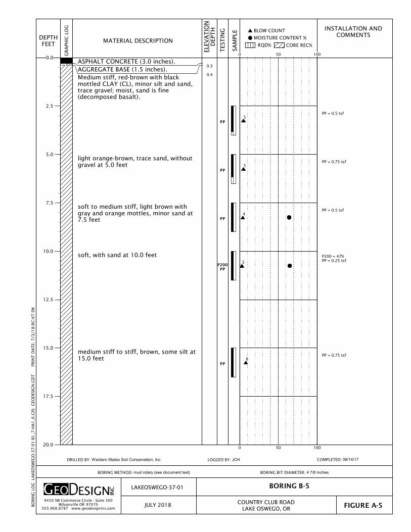
PP = 0.5 tsf
PP = 0.75 tsf
PP = 0.5 tsf
P200 = 47%PP = 0.25 tsf
PP = 0.75 tsf
0.3
0.4
PP
PP
PP
P200PP
PP
ASPHALT CONCRETE (3.0 inches).AGGREGATE BASE (1.5 inches).Medium stiff, red-brown with blackmottled CLAY (CL), minor silt and sand,trace gravel; moist, sand is fine(decomposed basalt).
light orange-brown, trace sand, withoutgravel at 5.0 feet
soft to medium stiff, light brown withgray and orange mottles, minor sand at7.5 feet
soft, with sand at 10.0 feet
medium stiff to stiff, brown, some silt at15.0 feet
INSTALLATION ANDCOMMENTS MOISTURE CONTENT %
CORE REC%RQD%
BLOW COUNT
BORING B-5
COMPLETED: 08/14/17
ELEV
AT
ION
DEP
TH
SAM
PLE
FIGURE A-5
BORING BIT DIAMETER: 4 7/8 inches
LAKE OSWEGO, OR
LAKEOSWEGO-37-01
COUNTRY CLUB ROAD
GRA
PHIC
LO
G
MATERIAL DESCRIPTION
TES
TIN
G
DEPTHFEET
LOGGED BY: JCH
JULY 20189450 SW Commerce Circle - Suite 300
Wilsonville OR 97070503.968.8787 www.geodesigninc.com
BORING METHOD: mud rotary (see document text)
DRILLED BY: Western States Soil Conservation, Inc.
BO
RIN
G L
OG
LA
KEO
SWEG
O-3
7-0
1-B
1_7
-HA
1_6
.GPJ
GEO
DES
IGN
.GD
T
PR
INT
DA
TE:
7/3
/18
:RC
:KT
:SN
0 50 100
0 50 100
0.0
2.5
5.0
7.5
10.0
12.5
15.0
17.5
20.0
5
5
4
3
8

Surface elevation was notmeasured at the time ofexploration.
20.0
26.5
Very dense, red-brown with gray andorange mottled, clayey GRAVEL (GC),minor sand, trace silt; moist(decomposed basalt).
dense, with sand at 25.0 feet
Exploration completed at a depth of26.5 feet.
Hammer efficiency factor is 78.7percent.
INSTALLATION ANDCOMMENTS MOISTURE CONTENT %
CORE REC%RQD%
BLOW COUNT
BORING B-5
COMPLETED: 08/14/17
ELEV
AT
ION
DEP
TH
SAM
PLE
FIGURE A-5
BORING BIT DIAMETER: 4 7/8 inches
LAKE OSWEGO, OR
LAKEOSWEGO-37-01
COUNTRY CLUB ROAD
GRA
PHIC
LO
G
MATERIAL DESCRIPTION
TES
TIN
G
(continued)
DEPTHFEET
LOGGED BY: JCH
JULY 20189450 SW Commerce Circle - Suite 300
Wilsonville OR 97070503.968.8787 www.geodesigninc.com
BORING METHOD: mud rotary (see document text)
DRILLED BY: Western States Soil Conservation, Inc.
BO
RIN
G L
OG
LA
KEO
SWEG
O-3
7-0
1-B
1_7
-HA
1_6
.GPJ
GEO
DES
IGN
.GD
T
PR
INT
DA
TE:
7/3
/18
:RC
:KT
:SN
0 50 100
0 50 100
20.0
22.5
25.0
27.5
30.0
32.5
35.0
37.5
40.0
60
36

Driller Comment:decomposed boulders from4.0 to 6.5 feet.
Hard drilling from 10.0 to12.0 feet. Possible boulder.
0.5
1.3
4.5
6.0
9.5
12.0
18.0
ASPHALT CONCRETE (6.0 inches).
AGGREGATE BASE (10.0 inches).
Very dense, light gray-brown GRAVELwith clay and sand (GP-GC), trace silt;moist (decomposed basalt).
Very dense, light gray GRAVEL (GP),trace silt, sand, and clay; moist(weathered basalt).
Medium dense, light gray-brown withyellow and orange mottled, clayeyGRAVEL with sand (GC), trace silt; moist(decomposed basalt).
Very dense, light gray GRAVEL (GP),trace silt, sand, and clay; moist(weathered basalt).
Medium dense, gray-brown, clayeyGRAVEL with sand (GC), trace silt; moist(decomposed basalt).
Very dense, light gray-brown with yellowmottled GRAVEL with clay (GP-GC),minor sand, trace silt; moist(decomposed basalt).
INSTALLATION ANDCOMMENTS MOISTURE CONTENT %
CORE REC%RQD%
BLOW COUNT
BORING B-6
COMPLETED: 08/14/17
ELEV
AT
ION
DEP
TH
SAM
PLE
FIGURE A-6
BORING BIT DIAMETER: 4 7/8 inches
LAKE OSWEGO, OR
LAKEOSWEGO-37-01
COUNTRY CLUB ROAD
GRA
PHIC
LO
G
MATERIAL DESCRIPTION
TES
TIN
G
DEPTHFEET
LOGGED BY: JCH
JULY 20189450 SW Commerce Circle - Suite 300
Wilsonville OR 97070503.968.8787 www.geodesigninc.com
BORING METHOD: mud rotary (see document text)
DRILLED BY: Western States Soil Conservation, Inc.
BO
RIN
G L
OG
LA
KEO
SWEG
O-3
7-0
1-B
1_7
-HA
1_6
.GPJ
GEO
DES
IGN
.GD
T
PR
INT
DA
TE:
7/3
/18
:RC
:KT
:SN
50/1"
50/3"
0 50 100
0 50 100
0.0
2.5
5.0
7.5
10.0
12.5
15.0
17.5
20.0
66
27
27

Surface elevation was notmeasured at the time ofexploration.
22.0
26.5
(continued from previous page)
Dense, light yellow-brown, clayey SANDwith gravel (SC), trace silt; moist(decomposed basalt).
Exploration completed at a depth of26.5 feet.
Hammer efficiency factor is 78.7percent.
INSTALLATION ANDCOMMENTS MOISTURE CONTENT %
CORE REC%RQD%
BLOW COUNT
BORING B-6
COMPLETED: 08/14/17
ELEV
AT
ION
DEP
TH
SAM
PLE
FIGURE A-6
BORING BIT DIAMETER: 4 7/8 inches
LAKE OSWEGO, OR
LAKEOSWEGO-37-01
COUNTRY CLUB ROAD
GRA
PHIC
LO
G
MATERIAL DESCRIPTION
TES
TIN
G
(continued)
DEPTHFEET
LOGGED BY: JCH
JULY 20189450 SW Commerce Circle - Suite 300
Wilsonville OR 97070503.968.8787 www.geodesigninc.com
BORING METHOD: mud rotary (see document text)
DRILLED BY: Western States Soil Conservation, Inc.
BO
RIN
G L
OG
LA
KEO
SWEG
O-3
7-0
1-B
1_7
-HA
1_6
.GPJ
GEO
DES
IGN
.GD
T
PR
INT
DA
TE:
7/3
/18
:RC
:KT
:SN
0 50 100
0 50 100
20.0
22.5
25.0
27.5
30.0
32.5
35.0
37.5
40.0
56
47

PP = 0.75 tsf
PP = 1.5 tsf
PP = 1.25 tsfLL = 67%PL = 25%
PP = 0.5 tsf
P200 = 42%PP = 1.0 tsf
0.5
1.5
PP
PP
ATTPP
PP
P200PP
ASPHALT CONCRETE (6.0 inches).
AGGREGATE BASE (12.0 inches).
Medium stiff, red-brown CLAY (CL),minor silt and sand, trace gravel; moist(decomposed basalt).red-brown with yellow mottles, withsand at 2.5 feet
stiff, red-brown with gray mottles, minorgravel at 5.0 feet
light brown, minor sand, trace gravel at7.5 feet
soft, light brown with gray mottles,trace to minor sand, without gravel at10.0 feet
medium stiff, light gray-brown, sandy at15.0 feet
INSTALLATION ANDCOMMENTS MOISTURE CONTENT %
CORE REC%RQD%
BLOW COUNT
BORING B-7
COMPLETED: 08/14/17
ELEV
AT
ION
DEP
TH
SAM
PLE
FIGURE A-7
BORING BIT DIAMETER: 4 7/8 inches
LAKE OSWEGO, OR
LAKEOSWEGO-37-01
COUNTRY CLUB ROAD
GRA
PHIC
LO
G
MATERIAL DESCRIPTION
TES
TIN
G
DEPTHFEET
LOGGED BY: JCH
JULY 20189450 SW Commerce Circle - Suite 300
Wilsonville OR 97070503.968.8787 www.geodesigninc.com
BORING METHOD: mud rotary (see document text)
DRILLED BY: Western States Soil Conservation, Inc.
BO
RIN
G L
OG
LA
KEO
SWEG
O-3
7-0
1-B
1_7
-HA
1_6
.GPJ
GEO
DES
IGN
.GD
T
PR
INT
DA
TE:
7/3
/18
:RC
:KT
:SN
0 50 100
0 50 100
0.0
2.5
5.0
7.5
10.0
12.5
15.0
17.5
20.0
6
11
11
3
7

PP = 2.0 tsf
Surface elevation was notmeasured at the time ofexploration.
21.0
26.5
PP
very stiff, light yellow-orange, minorsand, trace gravel at 20.0 feet
Very dense, light gray-brown withorange and yellow mottled, clayeyGRAVEL (GC), minor sand, trace silt;moist (decomposed basalt).
dense at 25.0 feet
Exploration completed at a depth of26.5 feet.
Hammer efficiency factor is 78.7percent.
INSTALLATION ANDCOMMENTS MOISTURE CONTENT %
CORE REC%RQD%
BLOW COUNT
BORING B-7
COMPLETED: 08/14/17
ELEV
AT
ION
DEP
TH
SAM
PLE
FIGURE A-7
BORING BIT DIAMETER: 4 7/8 inches
LAKE OSWEGO, OR
LAKEOSWEGO-37-01
COUNTRY CLUB ROAD
GRA
PHIC
LO
G
MATERIAL DESCRIPTION
TES
TIN
G
(continued)
DEPTHFEET
LOGGED BY: JCH
JULY 20189450 SW Commerce Circle - Suite 300
Wilsonville OR 97070503.968.8787 www.geodesigninc.com
BORING METHOD: mud rotary (see document text)
DRILLED BY: Western States Soil Conservation, Inc.
BO
RIN
G L
OG
LA
KEO
SWEG
O-3
7-0
1-B
1_7
-HA
1_6
.GPJ
GEO
DES
IGN
.GD
T
PR
INT
DA
TE:
7/3
/18
:RC
:KT
:SN
10-22-50/3"
0 50 100
0 50 100
20.0
22.5
25.0
27.5
30.0
32.5
35.0
37.5
40.0
35

Mulch underlain by fabric.
Surface elevation was notmeasured at the time ofexploration.
0.4
2.0
3.5
4.5
MULCH (5.0 inches).
Stiff, brown SILT (ML), minor sand,gravel, and clay, trace organics (roots,rootlets, charcoal); dry to moist(topsoil).
Stiff, light brown with gray and yellowmottled CLAY (CL), minor silt and sand,trace gravel and organics (rootlets); dryto moist (decomposed basalt).
Medium dense, red-brown with greenand orange mottled, clayey GRAVEL(GC), minor sand, trace silt; moist(decomposed basalt).
Exploration terminated at a depth of 4.5feet due to refusal.
INSTALLATION ANDCOMMENTS MOISTURE CONTENT %
CORE REC%RQD%
BLOW COUNT
BORING HA-1
COMPLETED: 08/17/17
ELEV
AT
ION
DEP
TH
SAM
PLE
FIGURE A-8
BORING BIT DIAMETER: 3 1/2 inches
LAKE OSWEGO, OR
LAKEOSWEGO-37-01
COUNTRY CLUB ROAD
GRA
PHIC
LO
G
MATERIAL DESCRIPTION
TES
TIN
G
DEPTHFEET
LOGGED BY: JCH
JULY 20189450 SW Commerce Circle - Suite 300
Wilsonville OR 97070503.968.8787 www.geodesigninc.com
BORING METHOD: hand auger (see document text)
DRILLED BY: GeoDesign, Inc. staff
BO
RIN
G L
OG
LA
KEO
SWEG
O-3
7-0
1-B
1_7
-HA
1_6
.GPJ
GEO
DES
IGN
.GD
T
PR
INT
DA
TE:
7/3
/18
:RC
:KT
:SN
0 50 100
0 50 100
0.0
2.5
5.0
7.5
10.0

Surface elevation was notmeasured at the time ofexploration.
0.3
3.0
5.5
MULCH (3.0 inches).
Medium stiff to stiff, light gray-brownSILT (ML), minor clay and sand, tracegravel and organics (rootlets, charcoal);dry to moist (topsoil) - FILL.
Stiff, light gray-brown CLAY (CL), minorsilt, trace sand and organics (rootlets);dry to moist.
minor sand, trace gravel at 5.0 feet
Exploration completed at a depth of 5.5feet.
INSTALLATION ANDCOMMENTS MOISTURE CONTENT %
CORE REC%RQD%
BLOW COUNT
BORING HA-2
COMPLETED: 08/17/17
ELEV
AT
ION
DEP
TH
SAM
PLE
FIGURE A-9
BORING BIT DIAMETER: 3 1/2 inches
LAKE OSWEGO, OR
LAKEOSWEGO-37-01
COUNTRY CLUB ROAD
GRA
PHIC
LO
G
MATERIAL DESCRIPTION
TES
TIN
G
DEPTHFEET
LOGGED BY: JCH
JULY 20189450 SW Commerce Circle - Suite 300
Wilsonville OR 97070503.968.8787 www.geodesigninc.com
BORING METHOD: hand auger (see document text)
DRILLED BY: GeoDesign, Inc. staff
BO
RIN
G L
OG
LA
KEO
SWEG
O-3
7-0
1-B
1_7
-HA
1_6
.GPJ
GEO
DES
IGN
.GD
T
PR
INT
DA
TE:
7/3
/18
:RC
:KT
:SN
0 50 100
0 50 100
0.0
2.5
5.0
7.5
10.0

Surface elevation was notmeasured at the time ofexploration.
2.0
4.5
Medium stiff, light brown SILT withsand (ML), trace gravel and organics(roots); dry to moist, sand is fine,organics are up to 3/4-inch diameter(3-inch-thick root zone) - FILL.
Medium stiff, light brown-orange SILTwith sand (ML); moist, sand is fine.
with gravel at 4.5 feetExploration terminated at a depth of 4.5feet due to refusal.
INSTALLATION ANDCOMMENTS MOISTURE CONTENT %
CORE REC%RQD%
BLOW COUNT
BORING HA-3
COMPLETED: 08/17/17
ELEV
AT
ION
DEP
TH
SAM
PLE
FIGURE A-10
BORING BIT DIAMETER: 3 1/2 inches
LAKE OSWEGO, OR
LAKEOSWEGO-37-01
COUNTRY CLUB ROAD
GRA
PHIC
LO
G
MATERIAL DESCRIPTION
TES
TIN
G
DEPTHFEET
LOGGED BY: JGH
JULY 20189450 SW Commerce Circle - Suite 300
Wilsonville OR 97070503.968.8787 www.geodesigninc.com
BORING METHOD: hand auger (see document text)
DRILLED BY: GeoDesign, Inc. staff
BO
RIN
G L
OG
LA
KEO
SWEG
O-3
7-0
1-B
1_7
-HA
1_6
.GPJ
GEO
DES
IGN
.GD
T
PR
INT
DA
TE:
7/3
/18
:RC
:KT
:SN
0 50 100
0 50 100
0.0
2.5
5.0
7.5
10.0

Surface elevation was notmeasured at the time ofexploration.
0.3
2.0
WOOD SHAVINGS (3.0 inches).
Stiff, brown SILT (ML), minor clay andsand, trace gravel and organics(rootlets, charcoal); moist (topsoil) -FILL.
Exploration terminated at a depth of 2.0feet due to refusal on gravel/decomposed basalt. Unable to sample.
INSTALLATION ANDCOMMENTS MOISTURE CONTENT %
CORE REC%RQD%
BLOW COUNT
BORING HA-4
COMPLETED: 08/17/17
ELEV
AT
ION
DEP
TH
SAM
PLE
FIGURE A-11
BORING BIT DIAMETER: 3 1/2 inches
LAKE OSWEGO, OR
LAKEOSWEGO-37-01
COUNTRY CLUB ROAD
GRA
PHIC
LO
G
MATERIAL DESCRIPTION
TES
TIN
G
DEPTHFEET
LOGGED BY: JCH
JULY 20189450 SW Commerce Circle - Suite 300
Wilsonville OR 97070503.968.8787 www.geodesigninc.com
BORING METHOD: hand auger (see document text)
DRILLED BY: GeoDesign, Inc. staff
BO
RIN
G L
OG
LA
KEO
SWEG
O-3
7-0
1-B
1_7
-HA
1_6
.GPJ
GEO
DES
IGN
.GD
T
PR
INT
DA
TE:
7/3
/18
:RC
:KT
:SN
0 50 100
0 50 100
0.0
2.5
5.0
7.5
10.0
Surface elevation was notmeasured at the time ofexploration.
2.5
4.5
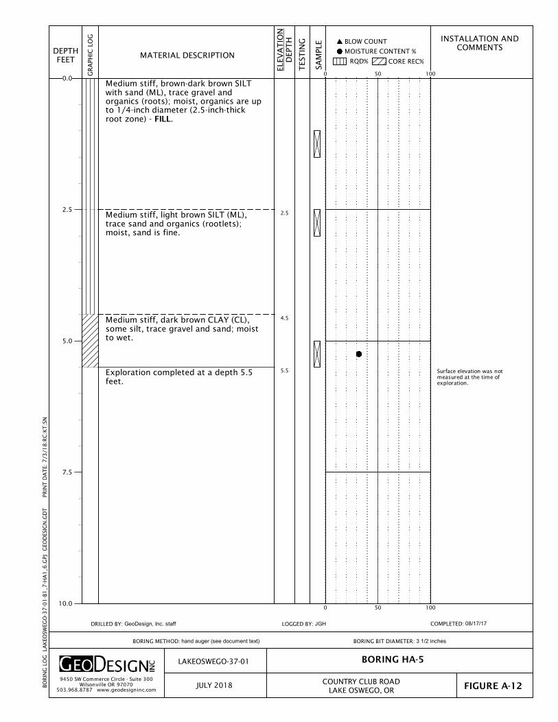
5.5
Medium stiff, brown-dark brown SILTwith sand (ML), trace gravel andorganics (roots); moist, organics are upto 1/4-inch diameter (2.5-inch-thickroot zone) - FILL.
Medium stiff, light brown SILT (ML),trace sand and organics (rootlets);moist, sand is fine.
Medium stiff, dark brown CLAY (CL),some silt, trace gravel and sand; moistto wet.
Exploration completed at a depth 5.5feet.
INSTALLATION ANDCOMMENTS MOISTURE CONTENT %
CORE REC%RQD%
BLOW COUNT
BORING HA-5
COMPLETED: 08/17/17
ELEV
AT
ION
DEP
TH
SAM
PLE
FIGURE A-12
BORING BIT DIAMETER: 3 1/2 inches
LAKE OSWEGO, OR
LAKEOSWEGO-37-01
COUNTRY CLUB ROAD
GRA
PHIC
LO
G
MATERIAL DESCRIPTION
TES
TIN
G
DEPTHFEET
LOGGED BY: JGH
JULY 20189450 SW Commerce Circle - Suite 300
Wilsonville OR 97070503.968.8787 www.geodesigninc.com
BORING METHOD: hand auger (see document text)
DRILLED BY: GeoDesign, Inc. staff
BO
RIN
G L
OG
LA
KEO
SWEG
O-3
7-0
1-B
1_7
-HA
1_6
.GPJ
GEO
DES
IGN
.GD
T
PR
INT
DA
TE:
7/3
/18
:RC
:KT
:SN
0 50 100
0 50 100
0.0
2.5
5.0
7.5
10.0

Surface elevation was notmeasured at the time ofexploration.
0.3
2.0
5.0
WOOD SHAVINGS (4.0 inches).
Stiff, brown SILT with sand (ML), minorclay, trace gravel and organics(charcoal, roots, rootlets); moist(topsoil) - FILL.
Stiff, red-brown CLAY (CL), minor siltand sand, trace organics (rootlets);moist.
with gravel at 4.0 feet
Exploration completed at a depth of 5.0feet.
INSTALLATION ANDCOMMENTS MOISTURE CONTENT %
CORE REC%RQD%
BLOW COUNT
BORING HA-6
COMPLETED: 08/17/17
ELEV
AT
ION
DEP
TH
SAM
PLE
FIGURE A-13
BORING BIT DIAMETER: 3 1/2 inches
LAKE OSWEGO, OR
LAKEOSWEGO-37-01
COUNTRY CLUB ROAD
GRA
PHIC
LO
G
MATERIAL DESCRIPTION
TES
TIN
G
DEPTHFEET
LOGGED BY: JCH
JULY 20189450 SW Commerce Circle - Suite 300
Wilsonville OR 97070503.968.8787 www.geodesigninc.com
BORING METHOD: hand auger (see document text)
DRILLED BY: GeoDesign, Inc. staff
BO
RIN
G L
OG
LA
KEO
SWEG
O-3
7-0
1-B
1_7
-HA
1_6
.GPJ
GEO
DES
IGN
.GD
T
PR
INT
DA
TE:
7/3
/18
:RC
:KT
:SN
0 50 100
0 50 100
0.0
2.5
5.0
7.5
10.0

9450 SW Commerce Circle - Suite 300
Wilsonville OR 97070 503.968.8787 www.geodesigninc.com
LAKEOSWEGO-37-01 CORE LOCATION AND CORE PHOTOGRAPHS
JULY 2018 COUNTRY CLUB ROAD
LAKE OSWEGO, OR FIGURE A-14
CORE LOCATION B-1.
CORE B-1.
Lake
Osw
ego-3
7-0
1-F
A14_A
17-C
PH.d
ocx
P
rint D
ate:
7/3
/18

9450 SW Commerce Circle - Suite 300
Wilsonville OR 97070 503.968.8787 www.geodesigninc.com
LAKEOSWEGO-37-01 CORE LOCATION AND CORE PHOTOGRAPHS
JULY 2018 COUNTRY CLUB ROAD
LAKE OSWEGO, OR FIGURE A-15
CORE LOCATION B-2.
CORE B-2.
Lake
Osw
ego-3
7-0
1-F
A14_A
17-C
PH.d
ocx
P
rint D
ate:
7/3
/18

9450 SW Commerce Circle - Suite 300
Wilsonville OR 97070 503.968.8787 www.geodesigninc.com
LAKEOSWEGO-37-01 CORE LOCATION AND CORE PHOTOGRAPHS
JULY 2018 COUNTRY CLUB ROAD
LAKE OSWEGO, OR FIGURE A-16
CORE LOCATION B-3.
CORE B-3.
Lake
Osw
ego-3
7-0
1-F
A14_A
17-C
PH.d
ocx
P
rint D
ate:
7/3
/18

9450 SW Commerce Circle - Suite 300
Wilsonville OR 97070 503.968.8787 www.geodesigninc.com
LAKEOSWEGO-37-01 CORE LOCATION AND CORE PHOTOGRAPHS
JULY 2018 COUNTRY CLUB ROAD
LAKE OSWEGO, OR FIGURE A-17
CORE LOCATION B-4.
CORE B-4.
Lake
Osw
ego-3
7-0
1-F
A14_A
17-C
PH.d
ocx
P
rint D
ate:
7/3
/18

0
10
20
30
40
50
60
70
80
90
100
110
ATTERBERG LIMITS TEST RESULTS
CL or OL
CL-ML ML or OL
MH or OH
"A" LINE
0 20 40 60 80 100 120 140 160 180
CH or OH
PLA
ST
ICIT
Y I
ND
EX
LIQUID LIMIT
LAKEOSWEGO-37-01
JULY 2018 COUNTRY CLUB ROADLAKE OSWEGO, OR FIGURE A-18
9450 SW Commerce Circle - Suite 300Wilsonville OR 97070
503.968.8787 www.geodesigninc.com
MOISTURE CONTENT(PERCENT)
7.5
1.0
7.5
40
28
35
EXPLORATIONNUMBER
SAMPLE DEPTH(FEET)
84
31
42
112
51
67
28
20
25
B-3
B-4
B-7
KEY LIQUID LIMIT PLASTIC LIMIT PLASTICITY INDEX
AT
TER
BER
G_L
IMIT
S 7
HIG
H L
LS
LAK
EOSW
EGO
-37
-01
-B1
_7-H
A1
_6.G
PJ
GEO
DES
IGN
.GD
T
PR
INT
DA
TE:
7/3
/18
:KT
:SN

B-1 1.5 21
B-3 7.5 40 112 28 84
B-3 15.0 37 43
B-3 20.0 35
B-4 1.0 28 51 20 31
B-5 7.5 64
B-5 10.0 65 47
B-6 7.5 25
B-7 5.0 41
B-7 7.5 35 67 25 42
B-7 15.0 51 42
HA-1 2.5 29
HA-2 3.5 20
HA-3 4.0 28
HA-4 1.0 20
HA-5 5.0 32
HA-6 2.0 23
GRAVEL(PERCENT)
SAMPLEDEPTH(FEET)
SUMMARY OF LABORATORY DATA
ELEVATION(FEET)
P200(PERCENT)
SIEVE
PLASTICLIMIT
PLASTICITYINDEX
ATTERBERG LIMITSMOISTURECONTENT(PERCENT)
SAMPLE INFORMATION
EXPLORATIONNUMBER
SAND(PERCENT)
DRYDENSITY
(PCF)LIQUIDLIMIT
LAKEOSWEGO-37-01
JULY 2018 COUNTRY CLUB ROADLAKE OSWEGO, OR FIGURE A-19
9450 SW Commerce Circle - Suite 300Wilsonville OR 97070
503.968.8787 www.geodesigninc.com
LAB
SUM
MA
RY
LAK
EOSW
EGO
-37
-01
-B1
_7-H
A1
_6.G
PJ
GEO
DES
IGN
.GD
T
PR
INT
DA
TE:
7/3
/18
:KT
:SN

GeoDesign, Inc. Page 1 of 5SPT Analyzer Results PDA-S Ver. 2015.14 - Printed: 1/24/2017
WSSC-8-01 RIG 4 - SERIAL NO. 137295
JDT Test date: 12/28/2016
AR: 1.41 in^2 SP: 0.492 k/ft3
LE: 22.50 ft EM: 30000 ksi
WS: 16807.9 ft/s
Depth: (15.50 - 16.50 ft], displaying BN: 9
[email protected] ft (60.000 kips)
[email protected] ft (23.8 ft/s)
TS: 81.92
TB: 0
A1,2
F1,2
LP: Length of Penetration BPM: Blows/Minute
FMX: Maximum Force EMX: Maximum Energy
VMX: Maximum Velocity ETR: Energy Transfer Ratio - Rated
BL# BC LP FMX VMX BPM EMX ETR
/6" ft kips ft/s bpm ft-lb (%)
1 3 15.67 39.467 10.9 40.9 254.2 72.6
2 3 15.83 40.708 11.4 41.0 268.2 76.6
3 3 16.00 40.463 11.4 40.9 276.4 79.0
4 8 16.06 39.591 11.4 41.1 269.7 77.0
5 8 16.13 41.269 11.5 40.9 274.2 78.3
6 8 16.19 40.182 11.2 41.0 264.3 75.5
7 8 16.25 40.409 10.0 41.1 249.4 71.3
8 8 16.31 39.368 10.0 41.0 248.6 71.0
9 8 16.38 40.145 10.3 41.1 249.1 71.2
10 8 16.44 39.985 9.7 41.1 254.8 72.8
11 8 16.50 41.756 10.9 41.2 256.4 73.3
Average 16.16 40.304 10.8 41.0 260.5 74.4
Std Dev 0.24 0.705 0.7 0.1 9.9 2.8
Maximum 16.50 41.756 11.5 41.2 276.4 79.0
Minimum 15.67 39.368 9.7 40.9 248.6 71.0
N-value: 11
Sample Interval Time: 14.59 seconds.

GeoDesign, Inc. Page 2 of 5SPT Analyzer Results PDA-S Ver. 2015.14 - Printed: 1/24/2017
Depth: (18.00 - 19.00 ft], displaying BN: 20
[email protected] ft (60.000 kips)
[email protected] ft (23.8 ft/s)
TS: 81.92
TB: 0
A1,2
F1,2
BL# BC LP FMX VMX BPM EMX ETR
/6" ft kips ft/s bpm ft-lb (%)
12 4 18.13 38.211 15.7 48.8 278.3 79.5
13 4 18.25 38.101 15.1 48.8 279.1 79.7
14 4 18.38 36.883 16.0 48.8 282.3 80.7
15 4 18.50 37.566 15.0 49.0 281.1 80.3
16 7 18.57 37.862 15.3 48.8 281.5 80.4
17 7 18.64 37.396 15.7 48.8 276.9 79.1
18 7 18.71 38.281 14.9 48.9 278.2 79.5
19 7 18.79 39.276 14.4 48.9 280.5 80.1
20 7 18.86 38.639 14.5 49.2 280.6 80.2
21 7 18.93 38.024 15.1 48.4 276.9 79.1
22 7 19.00 38.579 15.8 49.0 285.6 81.6
Average 18.61 38.074 15.2 48.9 280.1 80.0
Std Dev 0.27 0.623 0.5 0.2 2.5 0.7
Maximum 19.00 39.276 16.0 49.2 285.6 81.6
Minimum 18.13 36.883 14.4 48.4 276.9 79.1
N-value: 11
Sample Interval Time: 12.26 seconds.

GeoDesign, Inc. Page 3 of 5SPT Analyzer Results PDA-S Ver. 2015.14 - Printed: 1/24/2017
Depth: (20.50 - 21.50 ft], displaying BN: 35
[email protected] ft (60.000 kips)
[email protected] ft (23.8 ft/s)
TS: 81.92
TB: 0
A1,2
F1,2
BL# BC LP FMX VMX BPM EMX ETR
/6" ft kips ft/s bpm ft-lb (%)
23 6 20.58 40.982 15.3 44.1 274.1 78.3
24 6 20.67 39.106 15.7 44.5 270.6 77.3
25 6 20.75 38.916 15.3 44.2 271.4 77.5
26 6 20.83 39.724 15.5 44.4 273.9 78.2
27 6 20.92 38.029 15.7 44.4 271.9 77.7
28 6 21.00 38.778 14.9 44.3 276.3 78.9
29 9 21.06 38.254 14.7 44.3 273.2 78.1
30 9 21.11 39.220 14.4 44.4 275.8 78.8
31 9 21.17 39.485 15.0 44.4 277.1 79.2
32 9 21.22 40.190 14.3 44.3 274.6 78.5
33 9 21.28 38.950 14.5 44.4 278.0 79.4
34 9 21.33 38.594 14.3 44.3 277.6 79.3
35 9 21.39 38.404 13.7 44.4 273.5 78.1
36 9 21.44 37.484 14.2 44.4 276.2 78.9
37 9 21.50 37.301 14.2 44.4 276.7 79.1
Average 21.08 38.895 14.8 44.3 274.7 78.5
Std Dev 0.28 0.940 0.6 0.1 2.2 0.6
Maximum 21.50 40.982 15.7 44.5 278.0 79.4
Minimum 20.58 37.301 13.7 44.1 270.6 77.3
N-value: 15
Sample Interval Time: 19.00 seconds.

GeoDesign, Inc. Page 4 of 5SPT Analyzer Results PDA-S Ver. 2015.14 - Printed: 1/24/2017
Depth: (23.00 - 24.00 ft], displaying BN: 57
[email protected] ft (60.000 kips)
[email protected] ft (23.8 ft/s)
TS: 81.92
TB: 0
A1,2
F1,2
BL# BC LP FMX VMX BPM EMX ETR
/6" ft kips ft/s bpm ft-lb (%)
38 9 23.06 39.532 13.6 46.4 283.9 81.1
39 9 23.11 38.665 13.7 46.3 283.2 80.9
40 9 23.17 39.144 13.3 46.3 279.5 79.8
41 9 23.22 39.934 13.0 46.3 278.4 79.6
42 9 23.28 39.353 13.4 46.4 282.7 80.8
43 9 23.33 39.771 12.9 46.5 276.2 78.9
44 9 23.39 40.693 14.0 46.2 283.3 81.0
45 9 23.44 39.477 12.9 46.5 275.8 78.8
46 9 23.50 39.968 13.7 46.3 284.0 81.1
47 13 23.54 39.853 13.1 46.4 280.5 80.2
48 13 23.58 39.612 12.7 46.3 276.8 79.1
49 13 23.62 40.669 13.2 46.3 279.3 79.8
50 13 23.65 39.487 13.4 46.5 279.8 79.9
51 13 23.69 40.640 13.9 46.4 281.9 80.5
52 13 23.73 40.818 13.3 46.5 276.9 79.1
53 13 23.77 39.329 13.7 46.3 279.7 79.9
54 13 23.81 39.569 14.7 46.5 278.6 79.6
55 13 23.85 40.832 14.4 46.2 283.3 81.0
56 13 23.88 40.217 14.9 46.5 283.5 81.0
57 13 23.92 40.449 15.3 46.4 284.0 81.1
58 13 23.96 40.771 14.1 46.3 281.2 80.3
59 13 24.00 41.192 14.1 46.5 286.8 81.9
Average 23.57 39.999 13.7 46.4 280.9 80.3
Std Dev 0.28 0.658 0.7 0.1 2.9 0.8
Maximum 24.00 41.192 15.3 46.5 286.8 81.9
Minimum 23.06 38.665 12.7 46.2 275.8 78.8
N-value: 22
Sample Interval Time: 27.05 seconds.

GeoDesign, Inc. Page 5 of 5SPT Analyzer Results PDA-S Ver. 2015.14 - Printed: 1/24/2017
Summary of SPT Test Results
Project: WSSC-8-01, Test Date: 12/28/2016
LP: Length of Penetration BPM: Blows/Minute
FMX: Maximum Force EMX: Maximum Energy
VMX: Maximum Velocity ETR: Energy Transfer Ratio - Rated
Instr. Blows N N60 Average Average Average Average Average Average
Length Applied Value Value LP FMX VMX BPM EMX ETR
ft /6" ft kips ft/s bpm ft-lb (%)
22.50 3-8 8 10 16.16 40.304 10.8 41.0 260.5 74.4
22.50 4-7 7 9 18.61 38.074 15.2 48.9 280.1 80.0
22.50 6-9 9 11 21.08 38.895 14.8 44.3 274.7 78.5
22.50 9-13 13 17 23.57 39.999 13.7 46.4 280.9 80.3
Overall Average Values: 20.63 39.416 13.7 45.3 275.4 78.7
Standard Deviation: 2.80 1.109 1.6 2.5 9.0 2.6
Overall Maximum Value: 24.00 41.756 16.0 49.2 286.8 81.9
Overall Minimum Value: 15.67 36.883 9.7 40.9 248.6 71.0
Average Energy Transfer Ratio = 78.7%Energy Correction Factor = 1.31

APPENDIX B

B-1 LakeOswego-37-01:070318
APPENDIX B PRIOR EXPLORATIONS The exploration logs from our prior explorations in May 2010 are presented in this appendix.

LL = 61%PL = 21%
Core details:No patch observedCored on minor fatigue crack
Surface distress:Eastbound: Left lane - Minor tomoderate fatigueEastbound: Right lane - Patchy,severe fatigue crack in OWTWestbound: Left lane - MinorfatigueWestbound: Right lane - Severefatigue in OWT
LL = 61%PL = 21%
Core details:No patch observedCored on minor fatigue crack
Surface distress:Eastbound: Left lane - Minor tomoderate fatigueEastbound: Right lane - Patchy,severe fatigue crack in OWTWestbound: Left lane - MinorfatigueWestbound: Right lane - Severefatigue in OWT
LL = 61%PL = 21%
Core details:No patch observedCored on minor fatigue crack
Surface distress:Eastbound: Left lane - Minor tomoderate fatigueEastbound: Right lane - Patchy,severe fatigue crack in OWTWestbound: Left lane - MinorfatigueWestbound: Right lane - Severefatigue in OWT
LL = 61%PL = 21%
Core details:No patch observedCored on minor fatigue crack
Surface distress:Eastbound: Left lane - Minor tomoderate fatigueEastbound: Right lane - Patchy,severe fatigue crack in OWTWestbound: Left lane - MinorfatigueWestbound: Right lane - Severefatigue in OWT
0.7
1.2
3.0
ATT
ASPHALT CONCRETE (8 inches).
AGGREGATE BASE.
Medium stiff to stiff, dark brown CLAY(CL/CH), minor sand and silt; moist.
Exploration completed at a depth of 3.0feet.
BORING
COMMENTSCOMMENTSCOMMENTS MOISTURECONTENT % MOISTURECONTENT % COMMENTS
BLOW COUNTBO
RIN
G L
OG
- 2
PER
PA
GE
LA
KEO
SWEG
O-2
2-0
1-C
1_1
3-C
OU
NT
RY_C
LUB.G
PJ
GEO
DES
IGN
.GD
T
PRIN
T D
AT
E: 8
/16
/10
:KT
COMPLETED: 05/04/10
ELEV
AT
ION
DEP
TH
SAM
PLE
FIGURE A-24
BORING BIT DIAMETER: 4-inch
LAKE OSWEGO, OR
LAKEOSWEGO-22-01
LAKE OSWEGO PAVEMENT DESIGN - COUNTRY CLUB
GR
APH
IC L
OG
MATERIAL DESCRIPTION
TES
TIN
G
(continued)
DEPTHFEET
LOGGED BY: JGH
AUGUST 201015575 SW Sequoia Parkway - Suite 100
Portland OR 97224Off 503.968.8787 Fax 503.968.3068
BORING METHOD: core drill/solid-stem auger (see report text)
DRILLED BY: Dan J. Fischer Excavating, Inc.
Core details:No patch observedCored on minor fatigue crack
Surface distress:Eastbound: Left lane - Minorfatigue, minor to moderateravelingEastbound: Right lane - Minor tomoderate fatigue in the wheeltrack
Core details:No patch observedCored on minor fatigue crack
Surface distress:Eastbound: Left lane - Minorfatigue, minor to moderateravelingEastbound: Right lane - Minor tomoderate fatigue in the wheeltrack
Core details:No patch observedCored on minor fatigue crack
Surface distress:Eastbound: Left lane - Minorfatigue, minor to moderateravelingEastbound: Right lane - Minor tomoderate fatigue in the wheeltrack
Core details:No patch observedCored on minor fatigue crack
Surface distress:Eastbound: Left lane - Minorfatigue, minor to moderateravelingEastbound: Right lane - Minor tomoderate fatigue in the wheeltrack
0.5
1.8
3.5
ASPHALT CONCRETE (6.5 inches).
AGGREGATE BASE.
Very stiff to stiff, dark brown-orangeCLAY with sand (CL), minor silt andgravel; moist.becomes with gravel at 3.0 feet
Exploration completed at a depth of 3.5feet.
C-30.0
2.5
5.0
7.5
0 50 100
0 50 100C-4
0.0
2.5
5.0
7.5
0 50 100
0 50 100
888
161616

Core details:No patch observedNo crack on core
Surface distress:Eastbound: Left lane - Moderatefatigue crack on IWTEastbound: Right lane - Severefatigue in the wheel tracksWestbound: Right lane - Moderatefatigue in the wheel tracksWestbound: Left lane - Minorfatigue in the wheel tracks
Core details:No patch observedNo crack on core
Surface distress:Eastbound: Left lane - Moderatefatigue crack on IWTEastbound: Right lane - Severefatigue in the wheel tracksWestbound: Right lane - Moderatefatigue in the wheel tracksWestbound: Left lane - Minorfatigue in the wheel tracks
Core details:No patch observedNo crack on core
Surface distress:Eastbound: Left lane - Moderatefatigue crack on IWTEastbound: Right lane - Severefatigue in the wheel tracksWestbound: Right lane - Moderatefatigue in the wheel tracksWestbound: Left lane - Minorfatigue in the wheel tracks
Core details:No patch observedNo crack on core
Surface distress:Eastbound: Left lane - Moderatefatigue crack on IWTEastbound: Right lane - Severefatigue in the wheel tracksWestbound: Right lane - Moderatefatigue in the wheel tracksWestbound: Left lane - Minorfatigue in the wheel tracks
0.5
1.0
2.5
ASPHALT CONCRETE (6 inches).
PORTLAND CEMENT CONCRETE.
Medium stiff, dark gray SILT (ML), minorsand and gravel, trace organics (roots);moist.
Exploration completed at a depth of 2.5feet.
BORING
COMMENTSCOMMENTSCOMMENTS MOISTURECONTENT % MOISTURECONTENT % COMMENTS
BLOW COUNTBO
RIN
G L
OG
- 2
PER
PA
GE
LA
KEO
SWEG
O-2
2-0
1-C
1_1
3-C
OU
NT
RY_C
LUB.G
PJ
GEO
DES
IGN
.GD
T
PRIN
T D
AT
E: 8
/16
/10
:KT
COMPLETED: 05/04/10
ELEV
AT
ION
DEP
TH
SAM
PLE
FIGURE A-26
BORING BIT DIAMETER: 4-inch
LAKE OSWEGO, OR
LAKEOSWEGO-22-01
LAKE OSWEGO PAVEMENT DESIGN - COUNTRY CLUB
GR
APH
IC L
OG
MATERIAL DESCRIPTION
TES
TIN
G
(continued)
DEPTHFEET
LOGGED BY: JGH
AUGUST 201015575 SW Sequoia Parkway - Suite 100
Portland OR 97224Off 503.968.8787 Fax 503.968.3068
BORING METHOD: core drill/solid-stem auger (see report text)
DRILLED BY: Dan J. Fischer Excavating, Inc.
P200 = 45%
Core details:No patch observedCored on severe fatigue crack
Surface distress:Westbound: Right lane - Severefatigue in OWT, minor fatigue inIWTWestbound: Left lane - Moderatefatigue in IWT
P200 = 45%
Core details:No patch observedCored on severe fatigue crack
Surface distress:Westbound: Right lane - Severefatigue in OWT, minor fatigue inIWTWestbound: Left lane - Moderatefatigue in IWT
P200 = 45%
Core details:No patch observedCored on severe fatigue crack
Surface distress:Westbound: Right lane - Severefatigue in OWT, minor fatigue inIWTWestbound: Left lane - Moderatefatigue in IWT
P200 = 45%
Core details:No patch observedCored on severe fatigue crack
Surface distress:Westbound: Right lane - Severefatigue in OWT, minor fatigue inIWTWestbound: Left lane - Moderatefatigue in IWT
0.6
0.9
3.0
P200
ASPHALT CONCRETE (6.75 inches).
AGGREGATE BASE.Stiff, light gray-orange SILT with sand(ML), some clay, minor gravel; moist.
Exploration completed at a depth of 3.0feet.
C-70.0
2.5
5.0
7.5
0 50 100
0 50 100C-8
0.0
2.5
5.0
7.5
0 50 100
0 50 100
555
141414

LL = 32%PL = 20%
Core details:No patch observedCored on minor to moderate blockcrack
Surface distress:Westbound: Right lane - Moderateto severe fatigue on the wheeltracksWestbound: Left lane - Minor tomoderate fatigue cracking in thewheel tracks
LL = 32%PL = 20%
Core details:No patch observedCored on minor to moderate blockcrack
Surface distress:Westbound: Right lane - Moderateto severe fatigue on the wheeltracksWestbound: Left lane - Minor tomoderate fatigue cracking in thewheel tracks
LL = 32%PL = 20%
Core details:No patch observedCored on minor to moderate blockcrack
Surface distress:Westbound: Right lane - Moderateto severe fatigue on the wheeltracksWestbound: Left lane - Minor tomoderate fatigue cracking in thewheel tracks
LL = 32%PL = 20%
Core details:No patch observedCored on minor to moderate blockcrack
Surface distress:Westbound: Right lane - Moderateto severe fatigue on the wheeltracksWestbound: Left lane - Minor tomoderate fatigue cracking in thewheel tracks
0.5
1.0
2.5
ATT
ASPHALT CONCRETE (5.75 inches).
PORTLAND CEMENT CONCRETE.
Medium stiff, gray to dark gray SILT(ML), some clay, minor sand andorganics (wood fragments 1/4 inchthick); moist.Exploration completed at a depth of 2.5feet.
BORING
COMMENTSCOMMENTSCOMMENTS MOISTURECONTENT % MOISTURECONTENT % COMMENTS
BLOW COUNTBO
RIN
G L
OG
- 2
PER
PA
GE
LA
KEO
SWEG
O-2
2-0
1-C
1_1
3-C
OU
NT
RY_C
LUB.G
PJ
GEO
DES
IGN
.GD
T
PRIN
T D
AT
E: 8
/16
/10
:KT
COMPLETED: 05/05/10
ELEV
AT
ION
DEP
TH
SAM
PLE
FIGURE A-28
BORING BIT DIAMETER: 4-inch
LAKE OSWEGO, OR
LAKEOSWEGO-22-01
LAKE OSWEGO PAVEMENT DESIGN - COUNTRY CLUB
GR
APH
IC L
OG
MATERIAL DESCRIPTION
TES
TIN
G
(continued)
DEPTHFEET
LOGGED BY: JGH
AUGUST 201015575 SW Sequoia Parkway - Suite 100
Portland OR 97224Off 503.968.8787 Fax 503.968.3068
BORING METHOD: core drill/solid-stem auger (see report text)
DRILLED BY: Dan J. Fischer Excavating, Inc.
LL = 60%PL = 25%
Core details:No patch observedNo crack on core
Surface distress:Westbound: Right lane - Minorlongitudinal on the OWTWestbound: Left lane - Minorlongitudinal and minor raveling onthe IWT and OWTEastbound: Minor to moderateraveling
LL = 60%PL = 25%
Core details:No patch observedNo crack on core
Surface distress:Westbound: Right lane - Minorlongitudinal on the OWTWestbound: Left lane - Minorlongitudinal and minor raveling onthe IWT and OWTEastbound: Minor to moderateraveling
LL = 60%PL = 25%
Core details:No patch observedNo crack on core
Surface distress:Westbound: Right lane - Minorlongitudinal on the OWTWestbound: Left lane - Minorlongitudinal and minor raveling onthe IWT and OWTEastbound: Minor to moderateraveling
LL = 60%PL = 25%
Core details:No patch observedNo crack on core
Surface distress:Westbound: Right lane - Minorlongitudinal on the OWTWestbound: Left lane - Minorlongitudinal and minor raveling onthe IWT and OWTEastbound: Minor to moderateraveling
0.6
1.3
3.0
ATT
ASPHALT CONCRETE (7 inches).
AGGREGATE BASE.
Very stiff, dark brown-orange CLAY (CL),some silt, trace sand; moist.
Exploration completed at a depth of 3.0feet.
C-110.0
2.5
5.0
7.5
0 50 100
0 50 100C-12
0.0
2.5
5.0
7.5
0 50 100
0 50 100
666
242424

APPENDIX C

C-1 LakeOswego-37-01:070318
APPENDIX C FWD DATA GeoDesign completed deflection testing as listed in our August 2010 report. Additional details and calculations are presented in that report. This appendix presents the back-calculation results for AC over PCC pavement completed as part of that report.

D0 D8 D12 D18 D24 D36 D48 D60 D72
133 Eastbound 9,000 62.0 4.47 3.94 3.65 3.33 3.06 2.51 1.98 1.55 1.16 347 174 5,568,018 1.23 731
234 Eastbound 9,000 60.0 3.89 3.35 3.12 2.87 2.67 2.27 1.77 1.37 1.01 399 199 6,424,238 1.25 768
334 Eastbound 9,000 60.6 4.03 3.72 3.40 3.08 2.82 2.26 1.76 1.33 0.33 345 173 6,943,673 1.19 791
434 Eastbound 9,000 62.0 3.81 3.52 3.33 3.05 2.84 2.37 1.92 1.52 1.15 265 132 10,308,784 1.14 937
534 Eastbound 9,000 63.6 6.20 5.67 5.13 4.44 3.97 3.13 2.40 1.85 1.45 295 148 3,335,113 1.21 634
634 Eastbound 9,000 62.0 4.74 4.31 4.06 3.75 3.45 2.90 2.29 1.80 1.38 248 124 6,989,644 1.17 793
729 Eastbound 9,000 63.0 3.46 3.23 2.95 2.70 2.50 2.05 1.57 1.14 0.77 340 170 9,808,130 1.17 915
733 Eastbound 9,000 63.0 3.64 3.43 3.02 2.65 2.36 1.82 1.35 0.99 0.73 473 236 6,255,230 1.21 761
834 Eastbound 9,000 63.6 2.95 2.69 2.46 2.20 1.99 1.53 1.14 0.84 0.64 511 256 9,042,520 1.20 882
934 Eastbound 9,000 61.6 3.40 3.21 3.02 2.79 2.61 2.10 1.57 1.14 0.79 260 130 13,296,622 1.13 1,067
170 Westbound 9,000 61.3 4.08 3.86 3.73 3.49 2.99 2.24 1.76 1.33 1.01 258 129 9,141,493 1.09 886
270 Westbound 9,000 61.0 3.34 3.22 2.97 2.74 2.54 1.98 1.55 1.19 0.88 283 141 12,671,131 1.13 1,040
370 Westbound 9,000 60.6 4.36 4.28 4.06 3.68 3.35 2.16 1.57 1.25 0.99 227 113 9,087,549 1.07 884
471 Westbound 9,000 60.6 3.54 3.52 3.48 3.36 3.02 2.34 1.89 1.51 1.18 108 54 29,691,643 1.02 1,780
572 Westbound 9,000 63.6 4.06 4.04 3.91 3.54 3.18 2.62 2.08 1.65 1.37 151 75 16,124,840 1.04 1,190
670 Westbound 9,000 63.0 3.88 3.70 3.51 3.32 3.17 2.89 2.20 1.74 1.35 141 70 18,955,799 1.11 1,313
771 Westbound 9,000 62.3 3.31 3.03 2.88 2.70 2.56 2.14 1.61 1.17 0.84 262 131 14,010,534 1.15 1,098
870 Westbound 9,000 62.3 3.58 3.33 3.10 2.81 2.57 2.06 1.52 0.99 0.73 332 166 9,323,725 1.16 894
970 Westbound 9,000 61.6 3.00 2.85 2.66 2.42 2.23 1.77 1.31 0.88 0.64 327 164 13,702,033 1.13 1,085
1,071 Westbound 9,000 63.6 4.01 3.76 3.53 3.26 3.01 2.51 1.87 1.37 1.02 240 120 10,289,096 1.14 936
Lane
Back-Calculated Dynamick-value (psi/in)
Back-Calculated
Statick-value(psi/in)
Load(pounds)
Surface Temperature
(degrees Fahrenheit)
Normalized Deflections(mils)Approximate
Distance from 10th Street
(feet)
TABLE C-1FWD Results - AC over PCC Analysis
Country Club RoadLake Oswego, Oregon
Back-Calculated
PCCElastic
Modulus(psi)
BFactor
Back-Calculated
PCC Modulus of Rupture
(psi)
LakeOswego-37-01:070318

ACRONYMS AND ABBREVIATIONS

LakeOswego-37-01:070318
ACRONYMS AND ABBREVIATIONS AASHTO American Association of State Highway and Transportation Officials AC asphalt concrete ACP asphalt concrete pavement ASTM American Society for Testing and Materials BGS below ground surface BWT between wheel track EB eastbound ESAL equivalent single-axle load FDR full-depth reclamation FWD falling weight deflectometer H:V horizontal to vertical NA not applicable NP not present ODOT Oregon Department of Transportation OSHA Occupational Safety and Health Administration OSSC Oregon Standard Specifications for Construction (2015) OWT outside wheel track PCC portland cement concrete pcf pounds per cubic foot PG performance graded psi pounds per square inch psi/in pounds per square inch per inch SPT standard penetration test WB westbound