Embed Size (px)
Citation preview
1
GEORGIA INSTITUTE OF TECHNOLOGY George W. Woodruff School of Mechanical Engineering
ME 2110 - Creative Decisions and Design, Spring 2020 Studio #2 – Machining and Mechatronics
Studio Description: This studio contains two parts: IDEA laboratory training and mechatronics training. Each of these and the associated deliverables are described in the following. Members of your team will be divided into groups. In the first week, Group A will work on mechatronics and Group B will work on machining. In the next week, the groups will change places. IDEA Laboratory Safety: It is critical that you follow safe practices in use of the IDEA laboratory and other physical fabrication facilities. The machining and fabrication equipment in the IDEA laboratory involve hazards associated with kinetic energy, stored energy, sharps and pinch points, among others. If used improperly or negligently, these can cause severe injury and bodily harm. Soldering stations also can cause burns if used improperly. The instructional team will brief you on laboratory safety practices and you will be required to sign a user agreement form regarding safe use of the laboratory space before you can use equipment. Please consult a TA or instructor should you have any questions regarding safety. IDEA Laboratory Open Hours: In addition to doing work during your scheduled studio time, the IDEA Laboratory in MRDC 2101 will be open for other periods of time throughout the week. These periods are known as Open Studio. Any ME2110 student may use the IDEA Laboratory during Open Studio. The Open Studio schedule is posted on the ME2110 website. Due to limited time during scheduled studio, you will need to utilize Open Studio to complete your deliverables. Deliverable Schedule: This assignment will occur from Week 2 to Week 5, as noted on the course calendar posted on the ME2110 website. Table 1 shows the expected deliverables schedule and progress on this assignment. The machining parts and inspection sheet are to be turned in and counted as a homework grade. The mechatronics task sheet is a pass/fail component of the course.
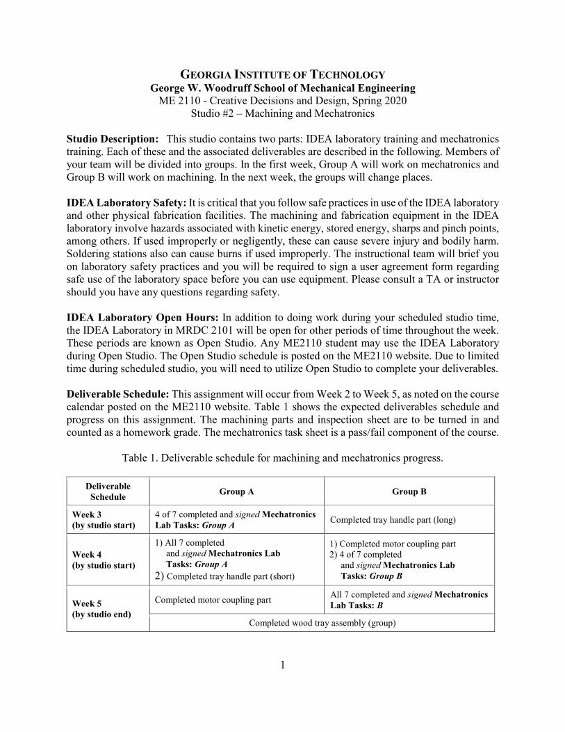
Table 1. Deliverable schedule for machining and mechatronics progress.
Deliverable Schedule Group A Group B
Week 3 (by studio start)
4 of 7 completed and signed Mechatronics Lab Tasks: Group A Completed tray handle part (long)
Week 4 (by studio start)
1) All 7 completed and signed Mechatronics Lab Tasks: Group A
2) Completed tray handle part (short)
1) Completed motor coupling part 2) 4 of 7 completed
and signed Mechatronics Lab Tasks: Group B
Week 5 (by studio end)
Completed motor coupling part All 7 completed and signed Mechatronics Lab Tasks: B
Completed wood tray assembly (group)
2
PART 1. MECHATRONICS TRAINING AND TASK SHEET.
Studio Description: This assignment is designed to give students the skills and experience to program the student embedded device (National Instruments myRIO) and to utilize the mechatronics kit, which integrates electrical, mechanical, and pneumatic systems. Students will be required to program the myRIO to accomplish various tasks involving mechatronics components. The myRIO utilizes a visual programming interface called LabVIEW. The lab comprises of two sections performed over three weeks. During the first week, Group A will complete one part of the lab, labeled “Mechatronics Lab Tasks: Group A;” during the second week, Group B will complete “Mechatronics Lab Tasks: Group B.” Although the programming style will not be graded, the programs created during these two labs should be helpful in developing the programs for the final project. Therefore, it is important to program using standard structure and commenting practices so that the program will be easy to follow when used as a reference later in the semester. Studio Tasks and Deliverables: 1. Complete mechatronics training. The student must attend the briefing given by the studio GTA. 2. Complete mechatronics task sheet. The student must complete the attached mechatronics task
sheets. To complete the task sheet, the student must demonstrate to the TA completion of the required task and provide a brief oral explanation of how the code accomplishes the required task. This is a pass/fail requirement for this class. The TAs will keep track of completed tasks using an online system and sign the task sheet when tasks are demonstrated. Each student should keep a signed copy of the task sheet for their records and as backup.
Mechatronics Kit: The mechatronics kit contains sensors, actuators, boards, power supplies and other components that will be used in this studio assignment and in the final project. Please note that your team will check out a mechatronics kit during studio. This kit is for your team to share and utilize over the duration of the studio assignment. It will be returned before the final project starts, at which point you will be placed on new teams. All individuals on the team are responsible for the complete return of this kit and all of its components in working condition. If your team is missing any components or have damaged components due to negligence, then you must replace these components immediately following the BOM links on the website. Students will not be given a final grade for this course until all kit materials have been returned. Instructions: Before attempting to perform these programming tasks, read the Mechatronics and Pneumatics Manual available on the course website. The manual provides background information on the layout of the National Instruments myRIO controller and explains how to implement the electro-mechanical-pneumatic components in a design. The manual also contains instructions for installing the required LabVIEW software on your computer. At the time of each checkpoint shown in Table 1, each student is responsible for showing progress through the assignment as indicated by a signed task checklist. The tasks for Group A and Group B, and the associated checklists, are provided on the subsequent two pages. After each task is completed, the operation must be successfully demonstrated to either the section instructor or a TA. The instructor or TA will initial the checklist confirming that the team has successfully completed that task element. Remember that each individual needs a separately signed checklist. Feel free to ask the instructor, TA, or peers for help in completion of this assignment, however, each student in the team must be prepared to answer questions about the program before the instructor/TA will initial the checklist.

3
Mechatronics Lab Tasks: Group A, Name:__________________________________________ 1. Connect 2 DC motors, 2 solenoids and 2 valves to the driver board. Connect all the sensors
to the sensor board. Study the LabVIEW programming template, and use the template to verify that every component operates correctly. In addition, look at the other VIs that are in the template, run them, and be prepared to briefly discuss what they do.
2. Follow the steps in this video: https://youtu.be/Ak-N8o6C7C0. As with all programs you create, be prepared to answer any questions about it.
3. Connect a potentiometer to the sensor board. Using the knob on the potentiometer, have it incrementally turn on the myRIO LEDs as you turn the knob; starting with LED0 and continuing until all 4 LEDs are lit. Use a chart to display the sensor voltage data continuously.
4. Connect a momentary switch to a Digital Input and have the DC motor run at full speed when the switch is held down and turn off when the switch is depressed. Each time the switch is pressed turn on LED1 for 1 second. The 1 second starts the moment when the switch is pressed, e.g. the LED will turn off after 1 second even if the switch is still held down. Hint: Connect the switch to a Digital Input, read in the value of the Digital Input when the button is pressed and the value of digital input when the button is released.
5. Connect two micro switches, the banana plugs and one pneumatic cylinder. The program starts with the cylinder retracted. The program starts by touching the banana plugs together. When switch one is pressed, the cylinder should extend and remain extended after the switch is released. When the other switch is pressed, the cylinder should retract and remain retracted. This loop continues while the banana plugs are held together. If the banana plugs are released at any time the cylinder is retracted immediately. The loop starts form the beginning when the plugs are retouched. Set this program to run automatically on startup (without being connected to the computer).
6. Connect two solenoids and two micro switches. When one micro switch is pressed, one solenoid is activated for 4 seconds and then released. When the other micro switch is pressed, the other solenoid is activated for 1750 ms and then released. When one actuator is active the other cannot be activated. Use LED1 and LED2 to indicate when each actuator is active. Hint: It may help to use “Elapsed time” and “Time Delay” Express VIs.
7. Connect 2 solenoids and two micro switches. At the beginning, have 1 solenoid activated. Once each switch has been pressed at least once and in any order (they don’t have to be held down together), the first solenoid will be deactivated and the second one will be activated for 5 seconds. After that, the cycle starts over. Two LEDs of your choosing will show states of the switches at all times (even when the first solenoid is off and the second is on).
* Stop each program with a button you create on the front panel, unless stated otherwise. Checklist for Group A: 1. __________ DATE: __________ 5. __________ DATE: __________ 2. __________ DATE: __________ 6. __________ DATE: __________ 3. __________ DATE: __________ 7. __________ DATE: __________ 4. __________ DATE: __________
4
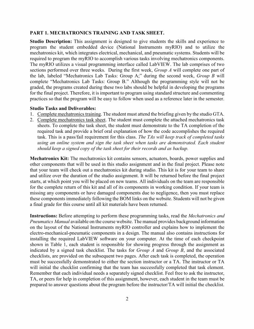
Mechatronics Lab Tasks: Group B, Name:__________________________________________ 1. Connect 2 DC motors, 2 solenoids and 2 valves to the driver board. Connect all the sensors
to the sensor board. Study the LabVIEW programming template, and use the template to verify that every component operates correctly. In addition, look at the other VIs that are in the template, run them, and be prepared to briefly discuss what they do.
2. Follow the steps in this video: https://youtu.be/Ak-N8o6C7C0. As with all programs you create, be prepared to answer any questions about it.
3. Connect both DC motors. Make them run clockwise for 5 seconds, stop for 2.5 seconds, run counter-clockwise for 5 seconds, and then stop for 2.5 seconds. Repeat this sequence 4 times. Hint: It may help to use “Elapsed time” and “Time Delay” Express VIs.
4. Connect the IR distance sensor and one DC motor. Have the motor run at 20% of its max speed for 5 seconds if the current IR sensor reading is greater than 1.2 V and the previous reading was below 1.2 V. Else the motor is running at full speed. Use a chart to display the IR sensor reading at all times. Hint: Consider using a shift register to record the previous IR sensor reading.
5. Connect the banana plugs and 2 DC motors. Run the first motor for 3 seconds after the banana plugs have been touched. Run the second motor for 4 seconds, 2 seconds after the banana plugs have been pressed. This loop continues while the banana plugs are held together. If the banana plugs are released at any time the motors stop. The loop starts form the beginning when the plugs are retouched. Set this program to run automatically on startup (without being connected to the computer).
6. Connect the encoder and the pneumatics. When the encoder is rotated 2 complete revolutions, the actuator should extend and remain extended until the encoder is rotated another 3 complete revolutions. Use an indicator on the front panel to display how many revolutions have been completed during each stage. The cylinder should only extend 4 times and then remain retracted regardless of how many times the encoder is rotated, but you should still show the encoder reading on the front panel.
7. Connect the 2 long-arm switches and one motor. At the beginning, the motor should run at 50% speed with all 4 LEDs turned on. After each switch has been pressed at least once and in any order (they don’t have to be held down together), the motor must switch direction for 3.5 seconds. After that, the cycle starts over. Turn off LED 1 when the first switch is pressed, turn off LED 2 when the second switch is pressed. The LEDs will need to indicate the switch state at all times (even when the motor has switched directions.) LED 0 and LED 3 should be on the entire time.
* Stop each program with a button you create on the front panel, unless stated otherwise.
Checklist for Group B: 1. __________ DATE: __________ 5. __________ DATE: __________ 2. __________ DATE: __________ 6. __________ DATE: __________ 3. __________ DATE: __________ 7. __________ DATE: __________ 4. __________ DATE: __________
5
PART 2. MACHINING TRAINING AND INSPECTION SHEET. Studio Description: This assignment is designed to give students the skills and experience to understand how an engineering drawing is used to manufacture a part to specification via machining methods with selected features being verified through inspection. The assignment has three tasks: (1) complete training, (2) machine 2 components: a tray handle and motor coupling, and (3) complete inspection reports for these components. The inspection report will be turned in along with the finished components and counted as a homework grade. Studio Tasks: 1. Complete training. The student must attend the machining briefing and IDEA laboratory safety
overview given by the studio GTA. The GTA will record the student’s attendance and completion of machining training in Canvas. This is a pass/fail requirement for this class. This training MUST be completed before the student can begin using IDEA lab equipment.
2. Complete machining of the required components. The student must complete machining of a motor mount and motor coupling according to the drawings in this document. A recommended process plan is provided that can be followed as a step-by-step process. For this assignment, only workpiece stock material provided by the ME2110 staff may be used. The studio TA team will record material usage in the form of number of workpieces requested. Your completion of this task will be evaluated based on: (1) material consumption and (2) satisfying the required tolerances for marked dimensions. Considerable divots/dings, inclusion of burrs, or addition of features not on the drawing are considered not to specification and each will be graded as a dimension not to specification. All features on the drawings must be produced, but only dimensions marked for inspection will be measured and evaluated for accuracy.
3. Complete inspection reports for the required components. The student must fill out an inspection report for the two components. This inspection report is attached to the end of this studio description document (.PDF). It should be filled out and submitted to Canvas by the required deadline.
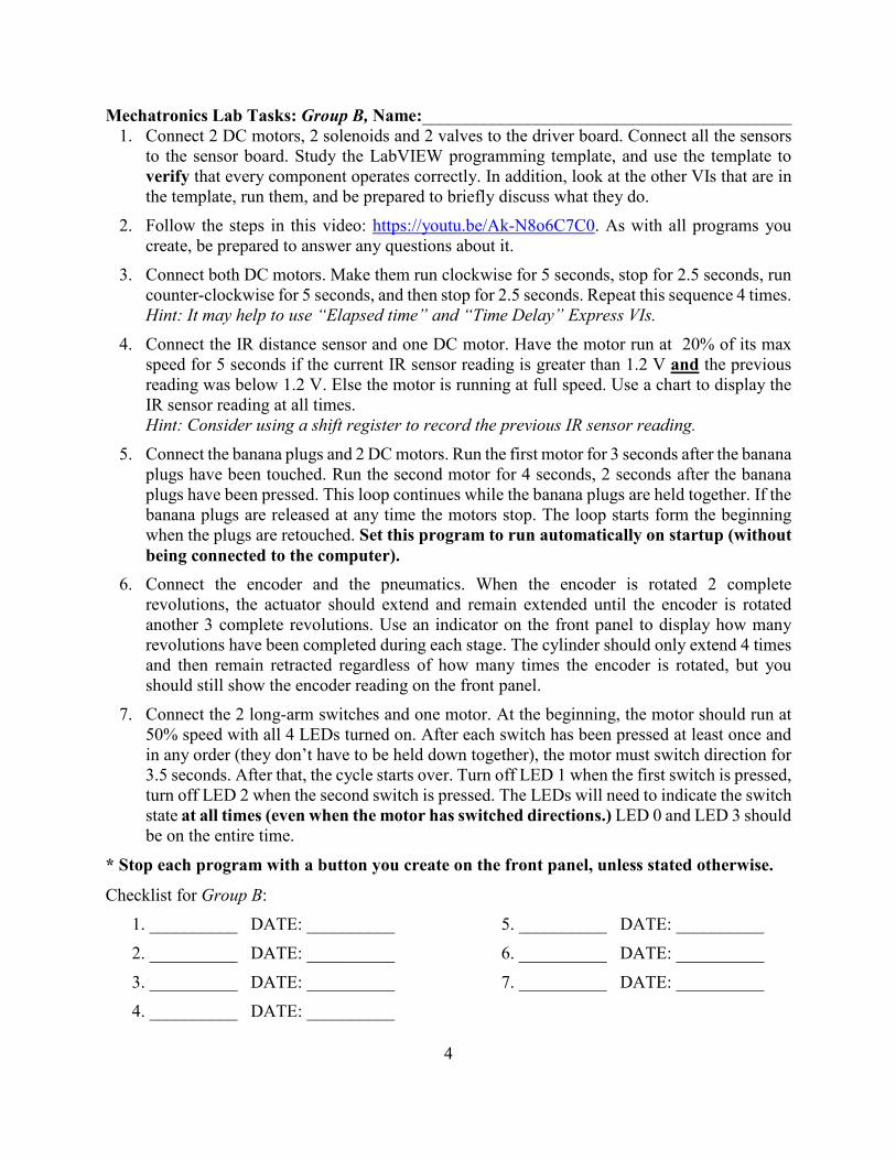
Assignment Grading Breakdown: Below is the rubric for the assignment. Each component (coupling, mount) constitutes 50% of this assignment. The following rubric will be used.
Category Criteria Score Material Usage (15%) 1 pieces of stock consumed
2-3 pieces of stock consumed 3 pieces of stock consumed (maximum is 3)
15% 10% 0%
Accuracy (20%) 0 marked dimension not to specification 1-2 marked dimensions not to specification 3 marked dimensions not to specification ≥ 4 marked dimensions not to specification
20% 15% 10% 0%
Appearance/Finish (5%) Part free of burrs, splinters, divots, extra features Part not free of burrs, splinters, divots, extra features
5% 0%
Inspection (10%) 0-1 measurements not within allowable deviation 2-3 measurements not within allowable deviation ≥ 4 measurements not within allowable deviation
10% 5% 0%
Total (50%) Maximum score per part 50%

6
5
1
2
3
4

7
Suggested Process Plan for Small DC Motor Coupling The below procedure is a suggested process plan for the small DC motor coupling. A visual representation of the major elements of this procedure, including fixturing, is shown in Figure 1. See the appendix for information on using the digital readout (DRO). 1. Obtain a piece of stock that meets outermost diameter and length specifications. Inspect the
stock upon receiving; do not use stock that does not meet specification. The stock should be long enough to allow it to be securely gripped in the chuck while leaving enough of the work exposed for machining.
2. Examine the drawing, making note of what datums each feature is referenced to. Throughout this process, be sure to consider these datums in how your part is fixed in the chuck.
3. Face the work, creating a face square to datum A. a. Take facing passes until a smooth, flat face is created on the part – there is no need to
reduce the work’s length any further than is necessary. If a nub is left on the face, ask a TA for assistance to adjust the tool height to address this.
4. Drill the ø 0.242” hole in the work. a. Use a drill chart to choose the properly sized drill. Use a drill chuck in the tailstock to
drill the hole. Gauge depth of the hole by noting when the drill enters the part and the scale on the quill and/or the dial on the quill feed.
5. Face the other end of the work, creating a face square to datum A. This face will be datum B. a. Flip the work in the chuck, bringing the other saw-cut face around for machining.
i. Note: The stock should also not be so far back in the chuck that calipers cannot be used to measure its entire length – this will be important later in this process plan. Check that calipers can fit around the length of the work while it is in the chuck.
b. Take facing passes until a smooth, flat face is created on the part – there is no need to reduce the work’s length any further than is necessary. On your final facing pass, mark the Z position of the tool. This corresponds to the Z position of the face.
6. Bring the work to final length. a. Just as before, face the work until a single smooth, flat surface is created square to
datum A. Mark this Z position on the DRO. b. With the work in the chuck, measure its length. Knowing the current length, final
length, and position of the tool (on the DRO), face until the final length is reached. 7. Turn down the stepped portion of the coupling to final diameter and shoulder location.
a. First, slowly move the tool towards the work along the X axis, until the first chips are made on the outer diameter of the work. This serves to approximately find the outer diameter of the work. Mark this X position on the DRO, as an approximate location of the outer diameter surface. **Note: Please be careful not to crash the tool or toolholder body into the chuck jaws. Check that the final length of your turning pass does not impact the chuck jaws.
b. Take a first roughing pass, turning down a small portion of the work where the step will be. You can use the DRO to gauge the depth of this first pass. Do not go past the step final diameter or shoulder location (having set the Z-zero on the DRO earlier to
8
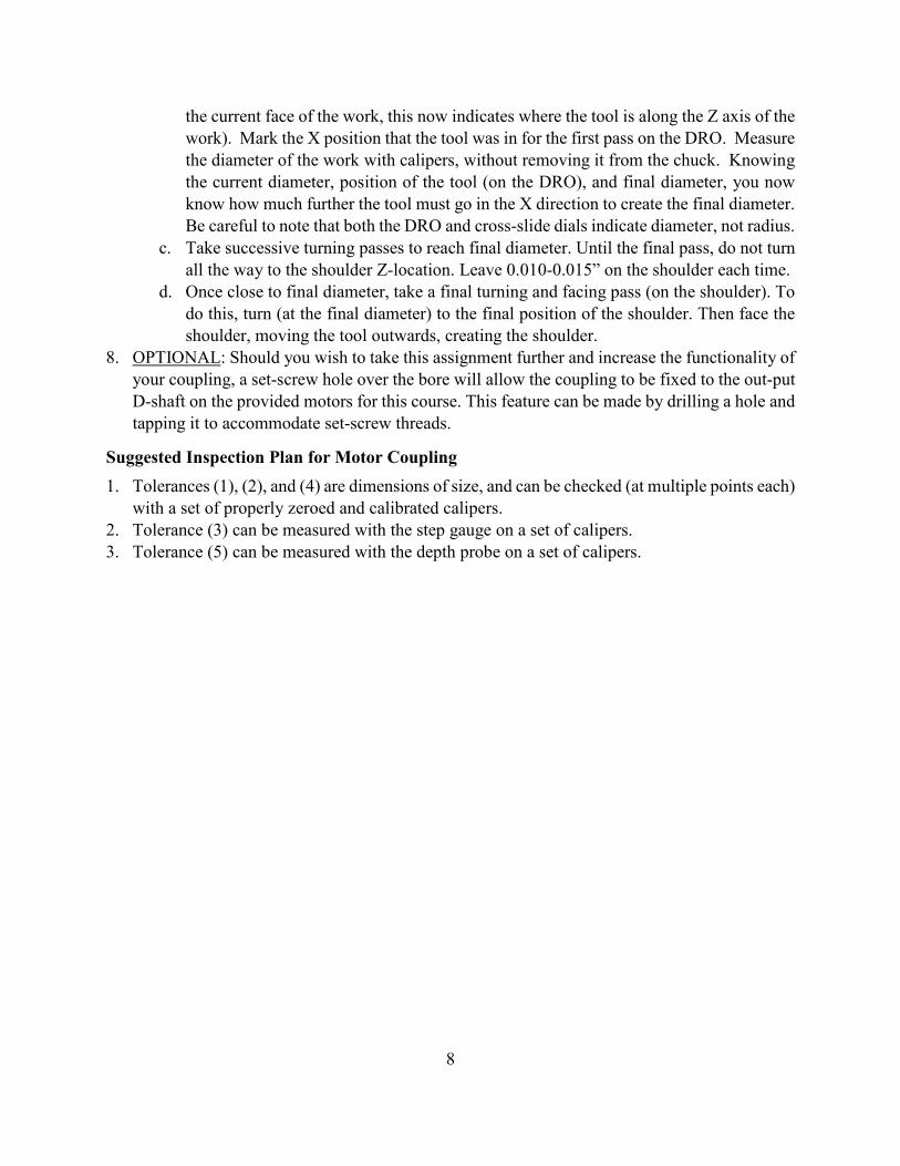
the current face of the work, this now indicates where the tool is along the Z axis of the work). Mark the X position that the tool was in for the first pass on the DRO. Measure the diameter of the work with calipers, without removing it from the chuck. Knowing the current diameter, position of the tool (on the DRO), and final diameter, you now know how much further the tool must go in the X direction to create the final diameter. Be careful to note that both the DRO and cross-slide dials indicate diameter, not radius.
c. Take successive turning passes to reach final diameter. Until the final pass, do not turn all the way to the shoulder Z-location. Leave 0.010-0.015” on the shoulder each time.
d. Once close to final diameter, take a final turning and facing pass (on the shoulder). To do this, turn (at the final diameter) to the final position of the shoulder. Then face the shoulder, moving the tool outwards, creating the shoulder.
8. OPTIONAL: Should you wish to take this assignment further and increase the functionality of your coupling, a set-screw hole over the bore will allow the coupling to be fixed to the out-put D-shaft on the provided motors for this course. This feature can be made by drilling a hole and tapping it to accommodate set-screw threads.
Suggested Inspection Plan for Motor Coupling 1. Tolerances (1), (2), and (4) are dimensions of size, and can be checked (at multiple points each)
with a set of properly zeroed and calibrated calipers. 2. Tolerance (3) can be measured with the step gauge on a set of calipers. 3. Tolerance (5) can be measured with the depth probe on a set of calipers.
9
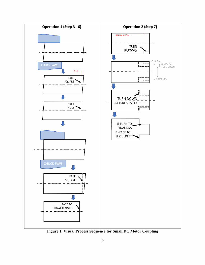
Operation 1 (Step 3 - 6)
Operation 2 (Step 7)
Figure 1. Visual Process Sequence for Small DC Motor Coupling

10
Suggested Process Plan for Tray Handle Part (individual) The below procedure is a suggested process plan for the tray handle part. 1. Obtain the piece of wood delegated to your team. 2. Examine the drawing and make note of appropriate tolerances for various dimensions. 3. Measure, mark and cut the board in half and give one part to your other group member and
keep the other for yourself.
Cut wood sides to length:
4. Cut 5’ (Group B) or 3’ (Group A) piece of wood into desired length for side of tray a. Mark the length of the desired cut on the stock piece of wood b. On the miter saw table, clamp your wood down to secure it from leaving the table
surface. Use your left hand to push the board against the back plate to secure the wood in the plane of the table, keep your fingers out of the marked danger zone. Use the miter saw to cut your piece of wood to the length specifications in your drawing. Remember, you can always make another cut or use a sander to make the wood shorter, but you cannot add length! Also note that pieces shorter than 5” in length, or pieces that cannot be clamped to the table, are not allowed to be cut by the miter saw.
c. If needed, use sandpaper to bring the piece to final dimension.
Make the tray side wall:
5. Make two 1” diameter holes on the drill press a. On your piece of wood, draw out the handle according to the drawing. Make sure you
locate the center of the 1” circle on each side of the handle feature. b. Clamp the wood to the drill table and before you drill to make sure it is secure. Use the
drill press with a 1” diameter forstner bit to create the hole in the marked locations. 6. Use the jig saw to cut the slot
a. Remove your piece of wood from the drill press, and move over to a table. b. Acquire two clamps to clamp the wood to the table so that a jigsaw can be used to cut
out the wood remaining between the two holes on each side of the handle. c. Insert jigsaw blade in one of the holes and cut the profile of the slot using the jigsaw.
Make sure that you will not cut the table when you use the jigsaw! Use a wood rasp to eliminate remaining tear-out.
7. Use the miter saw to cut the angle on the right side wall. a. Mark the angled features of the desired cut on the stock piece of wood. b. On the miter saw table, clamp your wood down to secure it from leaving the table
surface. Make sure the long side of the wood is always resting against the back of the fence. Orient the miter saw to the appropriate angle and lock it in place. Use your left hand to push the board against the back plate to secure the wood in the plane of the table, keep your fingers out of the marked danger zone. Use the miter saw to cut your piece of wood. Remember, you can always make another cut or use a sander to make the wood shorter, but you cannot add length! Also note that pieces shorter than 4” in
11
length, or pieces that cannot be clamped to the table, are not allowed to be cut by the miter saw.
8. Use the jigsaw to cut the angle feature on the left side wall. a. Acquire two clamps to clamp the wood to the table so that a jigsaw can be used to cut
the angled notched corner feature. b. Place the jigsaw blade along one of the sides and cut the profile of one of the edges
using the jigsaw. Be sure to stop when you reach the intersection of the two lines, then remove the jigsaw and cut the other profile, starting from the outside so that the two cuts meet up in the middle. Make sure that you will not cut the table when you use the jigsaw! Use a wood rasp to eliminate remaining tear-out.
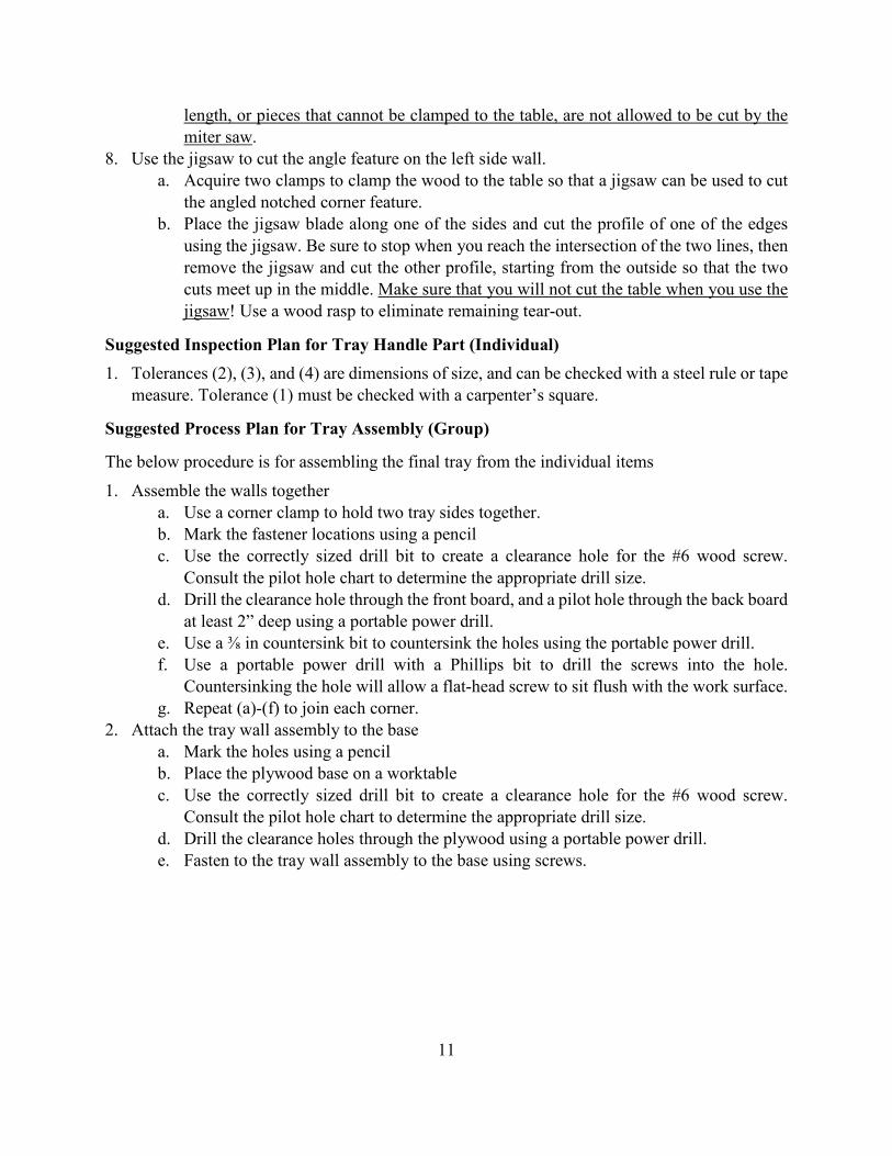
Suggested Inspection Plan for Tray Handle Part (Individual) 1. Tolerances (2), (3), and (4) are dimensions of size, and can be checked with a steel rule or tape
measure. Tolerance (1) must be checked with a carpenter’s square.
Suggested Process Plan for Tray Assembly (Group)
The below procedure is for assembling the final tray from the individual items 1. Assemble the walls together
a. Use a corner clamp to hold two tray sides together. b. Mark the fastener locations using a pencil c. Use the correctly sized drill bit to create a clearance hole for the #6 wood screw.
Consult the pilot hole chart to determine the appropriate drill size. d. Drill the clearance hole through the front board, and a pilot hole through the back board
at least 2” deep using a portable power drill. e. Use a ⅜ in countersink bit to countersink the holes using the portable power drill. f. Use a portable power drill with a Phillips bit to drill the screws into the hole.
Countersinking the hole will allow a flat-head screw to sit flush with the work surface. g. Repeat (a)-(f) to join each corner.
2. Attach the tray wall assembly to the base a. Mark the holes using a pencil b. Place the plywood base on a worktable c. Use the correctly sized drill bit to create a clearance hole for the #6 wood screw.
Consult the pilot hole chart to determine the appropriate drill size. d. Drill the clearance holes through the plywood using a portable power drill. e. Fasten to the tray wall assembly to the base using screws.
12
1
2
3
4

13

14

15
GEORGIA INSTITUTE OF TECHNOLOGY ME 2110 Creative Decisions and Design, Spring 2020
Fabrication and Inspection
Assigned: Week 2 (beginning of studio) Due: Week 5 (end of studio) Description: Understanding the role of quality in design and fabrication is a critical element of a successful engineer. You are asked to produce components to a specification and the customer will accept or reject your parts based on a formal drawing given to you as part of the contract. The dimensions that you must report are also marked in the attached images in this document. Provide a report of your final parts’ quality in the tables provided. Record a measurement of each marked dimension as-produced. Please use a pen to record your measurements. Do not fill in the TA Measurement column, this will be filled in by a studio TA or instructor. The TA will indicate using an ‘X’ if each dimension is within specification (pass) or out of specification (fail). The ranges given in the inspection portion of the grading rubric refer to the difference in the student’s stated measurement compared to the feature as measured by the studio TA or instructor. Requirements: This page should be filled out with the requested information and uploaded to Canvas before the deadline. You must turn in your finished components with this assignment. Student Name and Section: ____________________ TA Grader: ____________________ Tray Handle:
Dimension Tolerance Pass Fail Student
Measurement (in.)
TA Measurement
(in.)
Allowable Measurement
Deviation 1 ±1/8” ±1/16”
2 ±1/8” ±1/16”
3 ±1/8” ±1/16”
4 ±1/8” ±1/16”
Motor Coupling:
Dimension Tolerance Pass Fail Student
Measurement (in.)
TA Measurement
(in.)
Allowable Measurement
Deviation 1 ±0.005” ±0.0025”
2 ±0.010” ±0.005”
3 ±0.010” ±0.005”
4 ±0.010” ±0.005”
5 ±0.100" ±0.050"
16
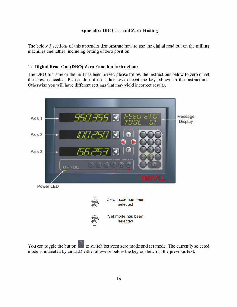
Appendix: DRO Use and Zero-Finding
The below 3 sections of this appendix demonstrate how to use the digital read out on the milling machines and lathes, including setting of zero position
1) Digital Read Out (DRO) Zero Function Instruction: The DRO for lathe or the mill has been preset, please follow the instructions below to zero or set the axes as needed. Please, do not use other keys except the keys shown in the instructions. Otherwise you will have different settings that may yield incorrect results.
You can toggle the button to switch between zero mode and set mode. The currently selected mode is indicated by an LED either above or below the key as shown in the previous text.

17
1. With Set mode selected, this enables the select axis keys to prompt a numeric entry into the desired axis. Once the correct value has been selected, it can be set as the axis value by pressing the enter key.
Or you can simply zero the selected axis by double pressing the axis select key, .
2. With the Zero mode selected, press the axis select key to zero the selected axis.
Procedures are the same for the DROs on the mills.
18
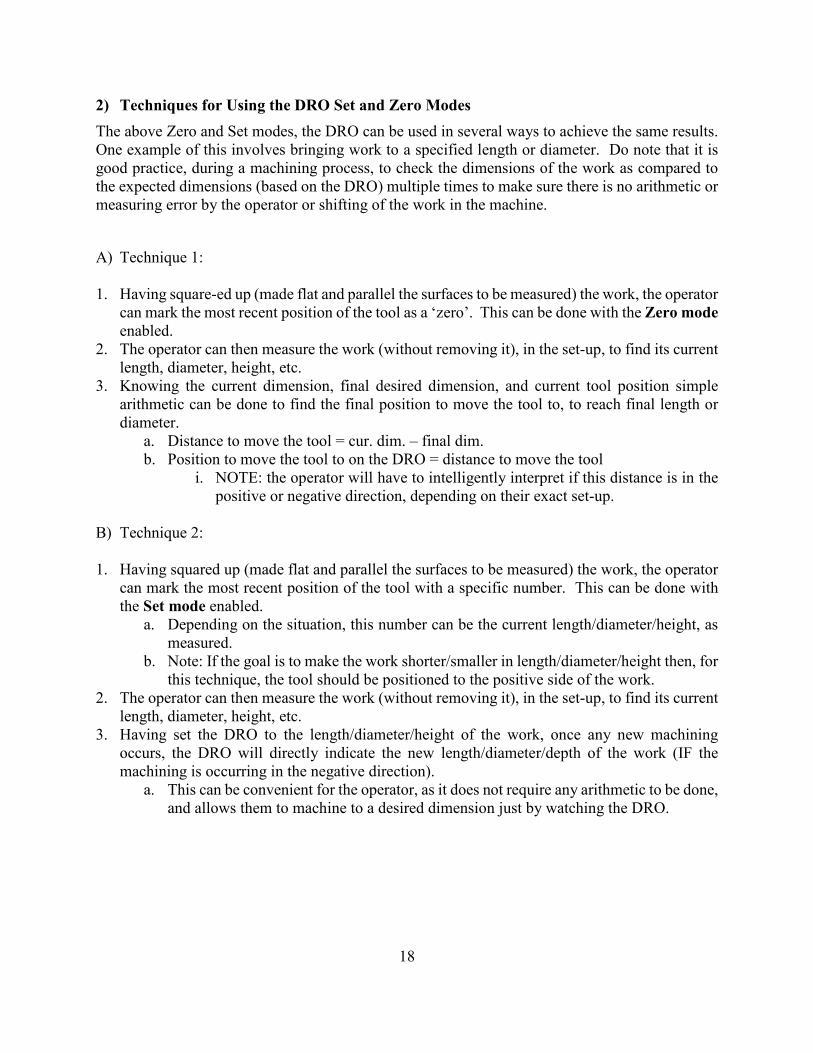
2) Techniques for Using the DRO Set and Zero Modes The above Zero and Set modes, the DRO can be used in several ways to achieve the same results. One example of this involves bringing work to a specified length or diameter. Do note that it is good practice, during a machining process, to check the dimensions of the work as compared to the expected dimensions (based on the DRO) multiple times to make sure there is no arithmetic or measuring error by the operator or shifting of the work in the machine. A) Technique 1:
1. Having square-ed up (made flat and parallel the surfaces to be measured) the work, the operator
can mark the most recent position of the tool as a ‘zero’. This can be done with the Zero mode enabled.
2. The operator can then measure the work (without removing it), in the set-up, to find its current length, diameter, height, etc.
3. Knowing the current dimension, final desired dimension, and current tool position simple arithmetic can be done to find the final position to move the tool to, to reach final length or diameter.
a. Distance to move the tool = cur. dim. – final dim. b. Position to move the tool to on the DRO = distance to move the tool
i. NOTE: the operator will have to intelligently interpret if this distance is in the positive or negative direction, depending on their exact set-up.
B) Technique 2:
1. Having squared up (made flat and parallel the surfaces to be measured) the work, the operator can mark the most recent position of the tool with a specific number. This can be done with the Set mode enabled.
a. Depending on the situation, this number can be the current length/diameter/height, as measured.
b. Note: If the goal is to make the work shorter/smaller in length/diameter/height then, for this technique, the tool should be positioned to the positive side of the work.
2. The operator can then measure the work (without removing it), in the set-up, to find its current length, diameter, height, etc.
3. Having set the DRO to the length/diameter/height of the work, once any new machining occurs, the DRO will directly indicate the new length/diameter/depth of the work (IF the machining is occurring in the negative direction).
a. This can be convenient for the operator, as it does not require any arithmetic to be done, and allows them to machine to a desired dimension just by watching the DRO.
19
3) Locating the part in space or finding part ‘Zero’ The DRO methods described in the previous sections assume that the operator has machined a new surface onto the work, the position of which is precisely known on the DRO. If the DRO is not set to correspond with a feature on the part, it is important to find the coordinates of the part so that the DRO readings will match the expected movement on the part and that the machining passes will create features with expected results. This is commonly needed when refixturing parts in the machine. In this situation, the operator has to find where the work is in the machine. In these cases, the operator will need to find where a surface of the work is and this will enable the operator to know where this surface is relative to the final feature on a part. This is especially critical if the part is precisely at its nominal dimensions and cannot be further machined any significant amount without affecting its ability to meet specified tolerances. The below methods are common methods for accomplishing these this location of the part in space.
It is critical that the part zero is found within a small positional increment (e.g., 0.001”) so to enable accurate determination of the correct part coordinates. If the part zero location is found at a poorer accuracy than this, then this will cause an issue with overall part accuracy. Note that these techniques are also useful for quickly and approximately finding ‘where’ the work is for initial machining/roughing (commonly known as ‘touching-off’), allowing the operator to gauge the depth of cut/tool engagement/etc. for the first roughing pass. Methods A and B can be used on either the milling machine or the lathe. Method C can only be used on the milling machine. A) The ‘Marker’ Method
1. This method relies on marking the part with ink, then determining at which point a tool rubs this mark away from the surface.
2. Using a Sharpie or other marker, make a mark on the work where a tool can be ‘touched-off’ against.
3. Very slowly and carefully, move the tool into the marked surface, until the operator can see the mark being barely machined away. Stop. Mark this position on the DRO for future reference as desired. Using this method (correctly) the work has only been machined a couple thousandths, at most.
4. If the smoothness of the surface is of concern, and the tool-mark is undesired, perform a ‘scratch-pass’ at this tool position, machining a new surface that should be only different by .001” or slightly greater from the previous surface.
B) ‘Kissing’ the Work
1. This method relies on determining at which point a tool starts contacting a work surface by visually identifying where scratches and/or chips are made on the surface.
2. Choose a location where a tool can be ‘touched-off’ against. 3. Very slowly and carefully, move the tool into the marked surface. The operator should be
looking for the very first chips to form off the surface. When the operator can see these first chips, stop. Mark this position on the DRO for future reference as desired. Using this method (correctly) the work has only been machined a couple thousandths, at most.
4. If the smoothness of the surface is of concern, and the tool-mark is undesired, perform a ‘scratch-pass’ at this tool position, machining a new surface that should be only different by .001” or slightly greater from the previous surface.


![Adaptive robust motion control of single-rod hydraulic actuators: …byao/Papers/Mechatronics... · 2010. 1. 13. · tive suspension control [3], and industrial hydraulic machines](https://img.dokumen.tips/doc/110x75/61388fd30ad5d20676495446/adaptive-robust-motion-control-of-single-rod-hydraulic-actuators-byaopapersmechatronics.jpg)