Embed Size (px)
Citation preview
GEORGIA DEPARTMENT of
TRANSPORTATION
Guidelines for Processing
Design Data in CAiCE Current with CAiCE Visual Transportation 10
Seventh Edition, Version 1.10
FEBRUARY 1, 2013
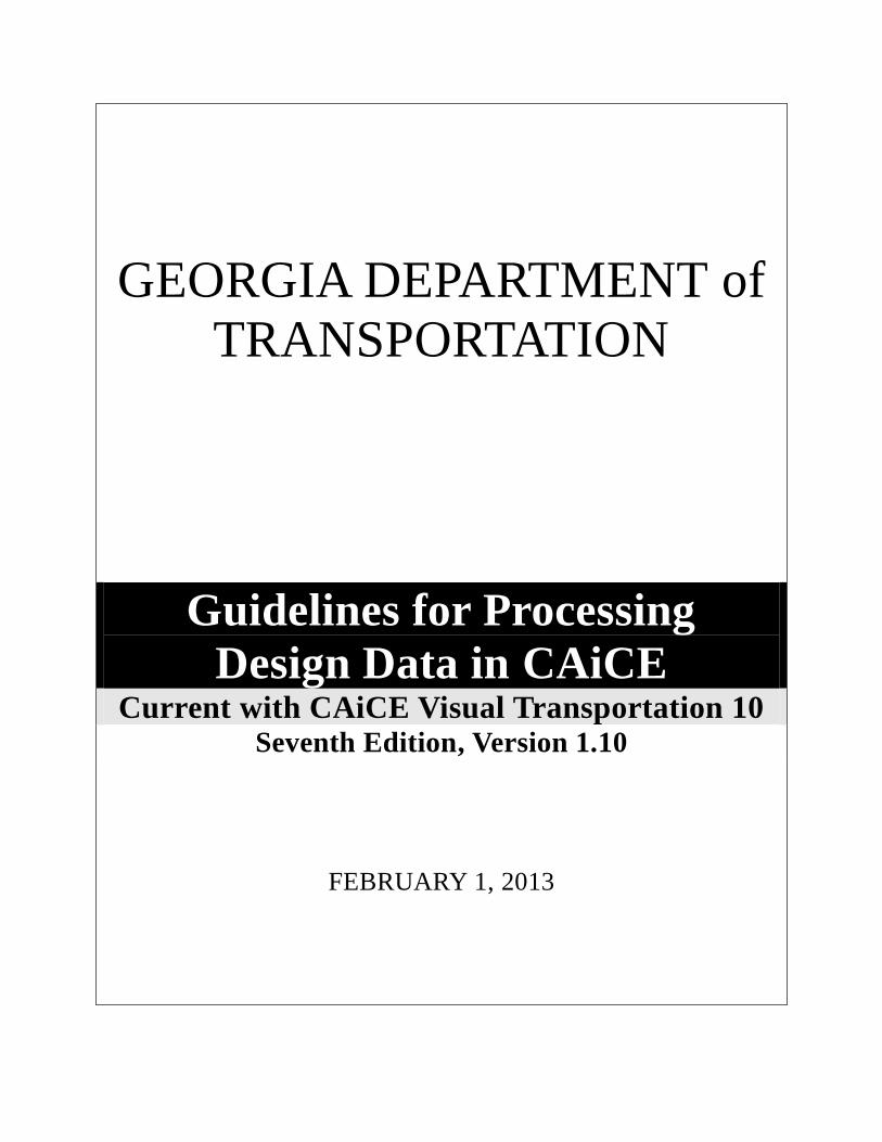
REVISION HISTORY
i
REVISION HISTORY
Date Revision Number By Section Description
Sept 27, 02 1.0 Joe Bozarth
Holly A. Cross
All Initial Document
Jan 8, 03 1.1 Holly A. Cross
Marlene E. Cole
All Reformatting
Sept 26, 03 1.2 Holly A. Cross All Updated screen captures
and text to correspond
with CAiCE VT 10
“ “ “ “ “ “ Sec 2/p 2-5 Added note to create
projects in Kcdata folder
“ “ “ “ “ “ Sec 2/p 2-11 Revised ‘Updating the
DTM Surface’ procedure
by adding error message
info to Step 4
“ “ “ “ “ “ Sec 4/p 4-3 Added note detailing
updated Archive
procedure
Oct 10, 03 1.3 Joe Bozarth Sec 7/p 7-2 Revised ‘Generate Deed
Files’ procedure to
reflect the new procedure
using the KCRW macro.
March 15,
04
1.4 Joe Bozarth Sec 1/p 1-2,
1-3
Appendix A
Added an entry in Table
1.1 for shoulder hinge
point chains. Added
entries in Table 1.2 for
detour centerline, edge of
paved shoulder, and
shoulder hinge point
feature codes. Added
Table 2.2, Table 3.1,
and Table 3.2 to
Appendix A.
Feb 15, 05 1.5 Holly A. Cross Sec 7/p 7-3,
7-4
Revised ‘Provide Files to
Contactors’ section to
reflect new procedure for
providing alignment
chain information to
contractors. Removed
the .KCM and .EAR file
requirements.

REVISION HISTORY
ii
REVISION HISTORY
Date Revision Number By Section Description
March 15,
06
1.6 Holly A. Cross Sec 1/p 1-10 Revised the Location of
web-page link to
download Project Data
Sheet Forms.
“ “ “ “ “ “ Sec 3/p 3-4,
3-5
Revised the Location of
web-page link to
download the GDOT
Standard Files
(CAiCEALL.exe).
“ “ “ “ “ “ Sec 5/p 5-7
Appendix A
p A-8
Added entries in Table
5.2 for EDG-2004
Version (Profile) Seed
files. Added entries in
Table 5.3 for EDG-2004
Version (Profile) Grid
files. Added table header
to Table 5.2 and Table
5.3 to reflect the EDG-
(Pre-2004) Version
(Profile) Seed/Grid files.
Updated Appendix to
reflect these changes to
Tables 5.2 & 5.3.
“ “ “ “ “ “ Sec 5/p 5-8
Updated Sec 5.3.1 Sheet
Format Selections to
include
XSEC-NARROW-EDG
& XSEC-WIDE-EDG.
“ “ “ “ “ “ Sec 5/p 5-12
Appendix A
p A-9
Added Section 5.3.5
(VBA Macro Plot and
Export X-Section Sheets).
Added entries in Table
5.4 for EDG-2004
X-Section Seed/Grid files
and EDG-(Pre-2004)
Seed/Grid files.
Updated Appendix to
reflect these changes to
Table 5.4.
“ “ “ “ “ “ Sec 5/p 5-13
Added examples of
EDG-2004/EDG-(Pre-
2004) X-Section Sheets.
Removed reference to
“old” x-section sheets.

REVISION HISTORY
iii
Date Revision Number By Section Description
Nov 1, 07 1.7 Holly A. Cross Sec 7/p7-3,
7-7,7-8
Revised ‘Provide Files to
Contractors’ section to
reflect new procedure for
providing GPS Grading
Report File information
to contractors.
Added additional
information regarding
Pre- and Post- Award
deliverable process.
Jan 1, 09 1.8 Holly A. Cross Sec 7/p7-3,
7-5,7-6
Revised ‘Provide Files to
Contractors’ section to
reflect an additional
procedure for providing
Alignment Report Files
for use in Contractor
GPS equipment.
Added additional
information regarding
Pre-Award deliverable
process for Alignment
Data.
“ “ “ “ “ “ Sec 1/p 1-10 Revised the Location of
web-page link to
download Project Data
Sheet Forms.
“ “ “ “ “ “ Sec 3/p 3-4,
3-5
Revised the Location of
web-page link to
download the GDOT
Standard Files
(CAiCEALL.exe).
Dec 1, 12 1.9 Holly A. Cross Sec 2/p 2-11 Updated document to
reflect the change from a
DTM LZH format to a
DTM ZIP compression
format for use in the
“Additional Survey Data
Macro”.
Feb 1, 13 1.10 Holly A. Cross Sec 7/p7-3,
7-8
Revised ‘Provide Files to
Contractors’ section to
reflect new procedure for
providing GPS Grading
Report File Pre-Award of
the Contract.


PREFACE
v
PREFACE
These guidelines have been developed as part of the ongoing statewide implementation of CAiCE.
The intent of this document is to provide guidelines and standards for processing design data in
CAiCE. The Design Guidelines must be followed in detail in order to conform to the GDOT
standards for producing the resulting DGN files used for plan production. Updates to this
document will be made periodically when minor revisions, additional information, and/or
enhancements are added.
It is the responsibility of the District SDE to prepare, convert, and enhance all mapping and survey
data prior to the delivery to the Project Manager or Designer. At no time should the Project
Manager or Designer revise, edit, or enhance survey data.
If there is any approved deviation from the standard file and data naming/feature code
conventions as prescribed by this document, a detailed description of the deviation(s) and
approved reasons for the deviation(s) shall be documented and included with the project files in
electronic format.
All electronic documentation files shall be provided in a Microsoft Word format and located in a
Documentation sub folder of the project directory.

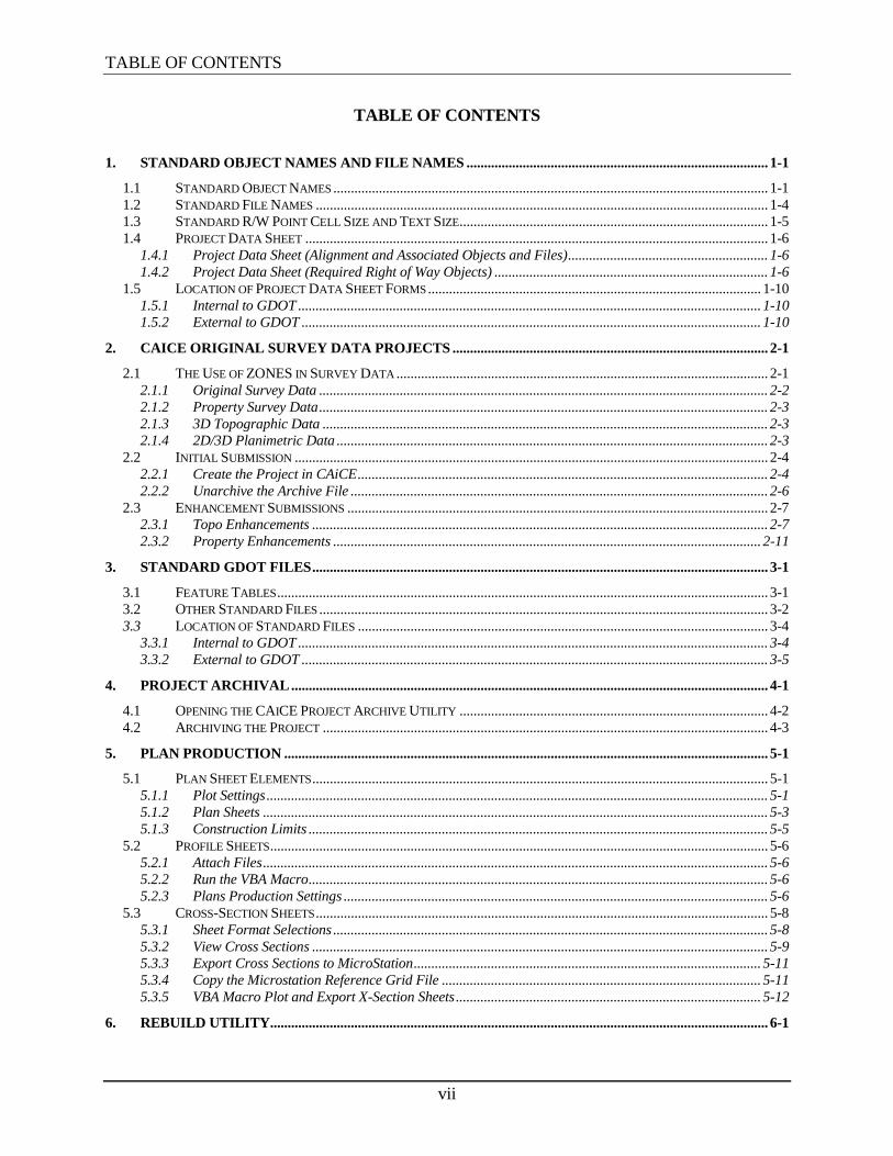
TABLE OF CONTENTS
vii
TABLE OF CONTENTS
1. STANDARD OBJECT NAMES AND FILE NAMES ...................................................................................... 1-1
1.1 STANDARD OBJECT NAMES ............................................................................................................................ 1-1 1.2 STANDARD FILE NAMES ................................................................................................................................. 1-4 1.3 STANDARD R/W POINT CELL SIZE AND TEXT SIZE ........................................................................................ 1-5 1.4 PROJECT DATA SHEET .................................................................................................................................... 1-6
1.4.1 Project Data Sheet (Alignment and Associated Objects and Files) ......................................................... 1-6 1.4.2 Project Data Sheet (Required Right of Way Objects) .............................................................................. 1-6
1.5 LOCATION OF PROJECT DATA SHEET FORMS ............................................................................................... 1-10 1.5.1 Internal to GDOT .................................................................................................................................... 1-10 1.5.2 External to GDOT ................................................................................................................................... 1-10
2. CAICE ORIGINAL SURVEY DATA PROJECTS .......................................................................................... 2-1
2.1 THE USE OF ZONES IN SURVEY DATA .......................................................................................................... 2-1 2.1.1 Original Survey Data ................................................................................................................................ 2-2 2.1.2 Property Survey Data ................................................................................................................................ 2-3 2.1.3 3D Topographic Data ............................................................................................................................... 2-3 2.1.4 2D/3D Planimetric Data ........................................................................................................................... 2-3
2.2 INITIAL SUBMISSION ....................................................................................................................................... 2-4 2.2.1 Create the Project in CAiCE ..................................................................................................................... 2-4 2.2.2 Unarchive the Archive File ....................................................................................................................... 2-6
2.3 ENHANCEMENT SUBMISSIONS ........................................................................................................................ 2-7 2.3.1 Topo Enhancements .................................................................................................................................. 2-7 2.3.2 Property Enhancements .......................................................................................................................... 2-11
3. STANDARD GDOT FILES .................................................................................................................................. 3-1
3.1 FEATURE TABLES ............................................................................................................................................ 3-1 3.2 OTHER STANDARD FILES ................................................................................................................................ 3-2 3.3 LOCATION OF STANDARD FILES ..................................................................................................................... 3-4
3.3.1 Internal to GDOT ...................................................................................................................................... 3-4 3.3.2 External to GDOT ..................................................................................................................................... 3-5
4. PROJECT ARCHIVAL ........................................................................................................................................ 4-1
4.1 OPENING THE CAICE PROJECT ARCHIVE UTILITY ........................................................................................ 4-2 4.2 ARCHIVING THE PROJECT ............................................................................................................................... 4-3
5. PLAN PRODUCTION .......................................................................................................................................... 5-1
5.1 PLAN SHEET ELEMENTS .................................................................................................................................. 5-1 5.1.1 Plot Settings ............................................................................................................................................... 5-1 5.1.2 Plan Sheets ................................................................................................................................................ 5-3 5.1.3 Construction Limits ................................................................................................................................... 5-5
5.2 PROFILE SHEETS .............................................................................................................................................. 5-6 5.2.1 Attach Files ................................................................................................................................................ 5-6 5.2.2 Run the VBA Macro ................................................................................................................................... 5-6 5.2.3 Plans Production Settings ......................................................................................................................... 5-6
5.3 CROSS-SECTION SHEETS ................................................................................................................................. 5-8 5.3.1 Sheet Format Selections ............................................................................................................................ 5-8 5.3.2 View Cross Sections .................................................................................................................................. 5-9 5.3.3 Export Cross Sections to MicroStation ................................................................................................... 5-11 5.3.4 Copy the Microstation Reference Grid File ........................................................................................... 5-11 5.3.5 VBA Macro Plot and Export X-Section Sheets ....................................................................................... 5-12
6. REBUILD UTILITY.............................................................................................................................................. 6-1
viii
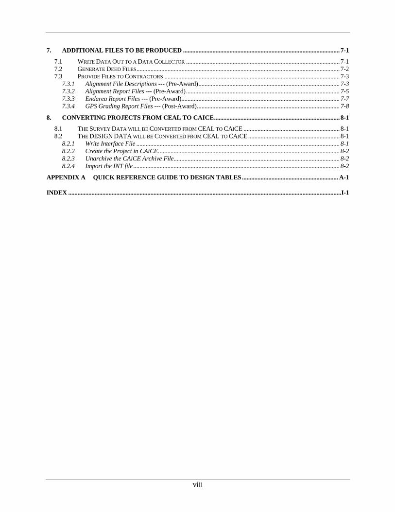
7. ADDITIONAL FILES TO BE PRODUCED ..................................................................................................... 7-1
7.1 WRITE DATA OUT TO A DATA COLLECTOR ................................................................................................... 7-1 7.2 GENERATE DEED FILES ................................................................................................................................... 7-2 7.3 PROVIDE FILES TO CONTRACTORS ................................................................................................................. 7-3
7.3.1 Alignment File Descriptions --- (Pre-Award) ........................................................................................... 7-3 7.3.2 Alignment Report Files --- (Pre-Award) ................................................................................................... 7-5 7.3.3 Endarea Report Files --- (Pre-Award) ...................................................................................................... 7-7 7.3.4 GPS Grading Report Files --- (Post-Award) ............................................................................................ 7-8
8. CONVERTING PROJECTS FROM CEAL TO CAICE ................................................................................. 8-1
8.1 THE SURVEY DATA WILL BE CONVERTED FROM CEAL TO CAICE .............................................................. 8-1 8.2 THE DESIGN DATA WILL BE CONVERTED FROM CEAL TO CAICE ........................................................... 8-1
8.2.1 Write Interface File ................................................................................................................................... 8-1 8.2.2 Create the Project in CAiCE. .................................................................................................................... 8-2 8.2.3 Unarchive the CAiCE Archive File........................................................................................................... 8-2 8.2.4 Import the INT file ..................................................................................................................................... 8-2
APPENDIX A QUICK REFERENCE GUIDE TO DESIGN TABLES .............................................................. A-1
INDEX ................................................................................................................................................................................ I-1

TABLE OF FIGURES
ix
TABLE OF FIGURES
Figure 1-1 ........................................................................................................................................... 1-7 Figure 1-2 ........................................................................................................................................... 1-8
Figure 1-3 ........................................................................................................................................... 1-9 Figure 2-1 ........................................................................................................................................... 2-4 Figure 2-2 ........................................................................................................................................... 2-5 Figure 2-3 ........................................................................................................................................... 2-6 Figure 2-4 ........................................................................................................................................... 2-8
Figure 2-5 ........................................................................................................................................... 2-9 Figure 2-6 .........................................................................................................................................2-10 Figure 2-7 .........................................................................................................................................2-12 Figure 4-1 ........................................................................................................................................... 4-2
Figure 4-2 ........................................................................................................................................... 4-3 Figure 4-3 ........................................................................................................................................... 4-4
Figure 5-1 ........................................................................................................................................... 5-1 Figure 5-2 ........................................................................................................................................... 5-2
Figure 5-3 ........................................................................................................................................... 5-3 Figure 5-4 ........................................................................................................................................... 5-3 Figure 5-5 ........................................................................................................................................... 5-4
Figure 5-6 ........................................................................................................................................... 5-5 Figure 5-7 ........................................................................................................................................... 5-8
Figure 5-8 ........................................................................................................................................... 5-9 Figure 5-9 .........................................................................................................................................5-10 Figure 5-10 .......................................................................................................................................5-10
Figure 5-11 .......................................................................................................................................5-11
Figure 5-12 .......................................................................................................................................5-13 Figure 5-13 .......................................................................................................................................5-13 Figure 7-1 ........................................................................................................................................... 7-1
Figure 7-2 ........................................................................................................................................... 7-2 Figure 7-3 ........................................................................................................................................... 7-3
Figure 7-4 ........................................................................................................................................... 7-4 Figure 7-5 ........................................................................................................................................... 7-5
Figure 7-6 ........................................................................................................................................... 7-6 Figure 7-7 ........................................................................................................................................... 7-7 Figure 7-8 ........................................................................................................................................... 7-8 Figure 8-1 ........................................................................................................................................... 8-2 Figure 8-2 ........................................................................................................................................... 8-3
Figure 8-3 ........................................................................................................................................... 8-3


TABLE OF TABLES
xi
TABLE OF TABLES
Table 1.1 ............................................................................................................................................. 1-2
Table 1.2 ............................................................................................................................................. 1-3
Table 1.3 ............................................................................................................................................. 1-4
Table 1.4 ............................................................................................................................................. 1-5
Table 2.1 ............................................................................................................................................. 2-1
Table 2.2 ............................................................................................................................................. 2-2
Table 3.1 ............................................................................................................................................. 3-1
Table 3.2 ............................................................................................................................................. 3-2
Table 5.1 ............................................................................................................................................. 5-7
Table 5.2 ............................................................................................................................................. 5-7
Table 5.3 ............................................................................................................................................. 5-7
Table 5.4 ...........................................................................................................................................5-12

Overview
xii
OVERVIEW
These Guidelines cover the beginning process of project design utilizing CAiCE survey data,
standards for storing objects within CAiCE, brief explanations of all the standard files, automated
design processes within the Department, plan production, and other information.
Document Content
Below is a list of topics covered in this document:
● Standard Object Names and File Names
● CAiCE Original Survey Data Projects
● Standard GDOT Files
● Project Archival
● Plan Production
● Rebuild Utility
● Additional Files to be Produced
● Converting Projects from CEAL to CAiCE
● Appendix
● Index

1. Standard Object Names and File Names
Standard Object Names and File Names
1-1
1. Standard Object Names and File Names
Standard object and file naming conventions have been established in order to promote consistency
and assist in the organization of project data. These standard naming schemes help to ensure
uniformity for all users who may work on the project.
This section covers the following topics:
● Standard Object Names
● Standard File Names
● Standard R/W Point Cell Size and Text Size
● Project Data Sheet
● Location of Project Data Sheet Forms
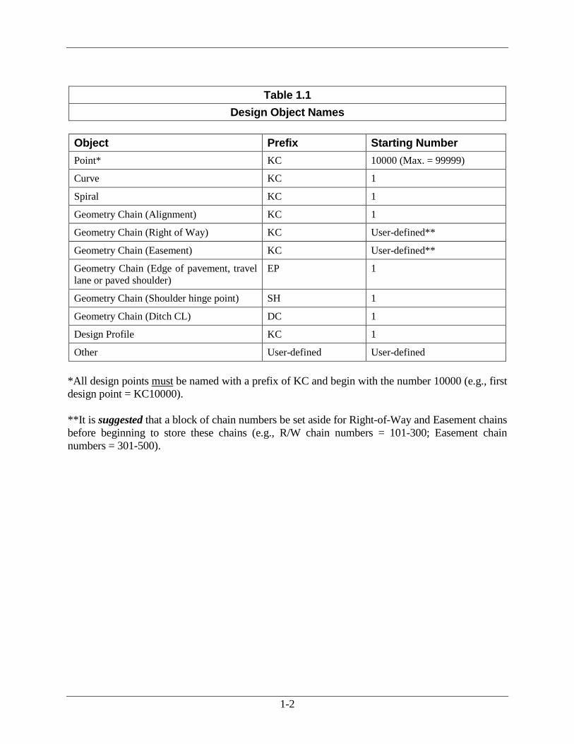
1.1 Standard Object Names The designer shall follow the guidelines on the following page (see Table 1.1 and Table 1.2)
when storing design objects in CAiCE. These guidelines must be followed in order to
conform to current GDOT standards and policies. Use only one prefix for points in CAiCE.
This eliminates the possibility of duplicate points going back to the Data Collector.
Note: All standard design object names must begin with the prescribed prefix. Please see
the guidelines in Table 1.1 for additional information.
1-2
Table 1.1
Design Object Names
Object Prefix Starting Number
Point* KC 10000 (Max. = 99999)
Curve KC 1
Spiral KC 1
Geometry Chain (Alignment) KC 1
Geometry Chain (Right of Way) KC User-defined**
Geometry Chain (Easement) KC User-defined**
Geometry Chain (Edge of pavement, travel
lane or paved shoulder)
EP 1
Geometry Chain (Shoulder hinge point) SH 1
Geometry Chain (Ditch CL) DC 1
Design Profile KC 1
Other User-defined User-defined
*All design points must be named with a prefix of KC and begin with the number 10000 (e.g., first
design point = KC10000).
**It is suggested that a block of chain numbers be set aside for Right-of-Way and Easement chains
before beginning to store these chains (e.g., R/W chain numbers = 101-300; Easement chain
numbers = 301-500).
1-3
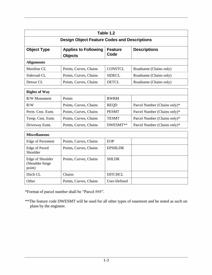
Table 1.2
Design Object Feature Codes and Descriptions
Object Type Applies to Following
Objects
Feature Code
Descriptions
Alignments
Mainline CL Points, Curves, Chains CONSTCL Roadname (Chains only)
Sideroad CL Points, Curves, Chains SIDECL Roadname (Chains only)
Detour CL Points, Curves, Chains DETCL Roadname (Chains only)
Rights of Way
R/W Monument Points RWRM
R/W Points, Curves, Chains REQD Parcel Number (Chains only)*
Perm. Cnst. Esmt. Points, Curves, Chains PESMT Parcel Number (Chains only)*
Temp. Cnst. Esmt. Points, Curves, Chains TESMT Parcel Number (Chains only)*
Driveway Esmt. Points, Curves, Chains DWESMT** Parcel Number (Chains only)*
Miscellaneous
Edge of Pavement Points, Curves, Chains EOP
Edge of Paved
Shoulder
Points, Curves, Chains EPSHLDR
Edge of Shoulder
(Shoulder hinge
point)
Points, Curves, Chains SHLDR
Ditch CL Chains DITCHCL
Other Points, Curves, Chains User-Defined
*Format of parcel number shall be “Parcel ###”.
**The feature code DWESMT will be used for all other types of easement and be noted as such on
plans by the engineer.
1-4
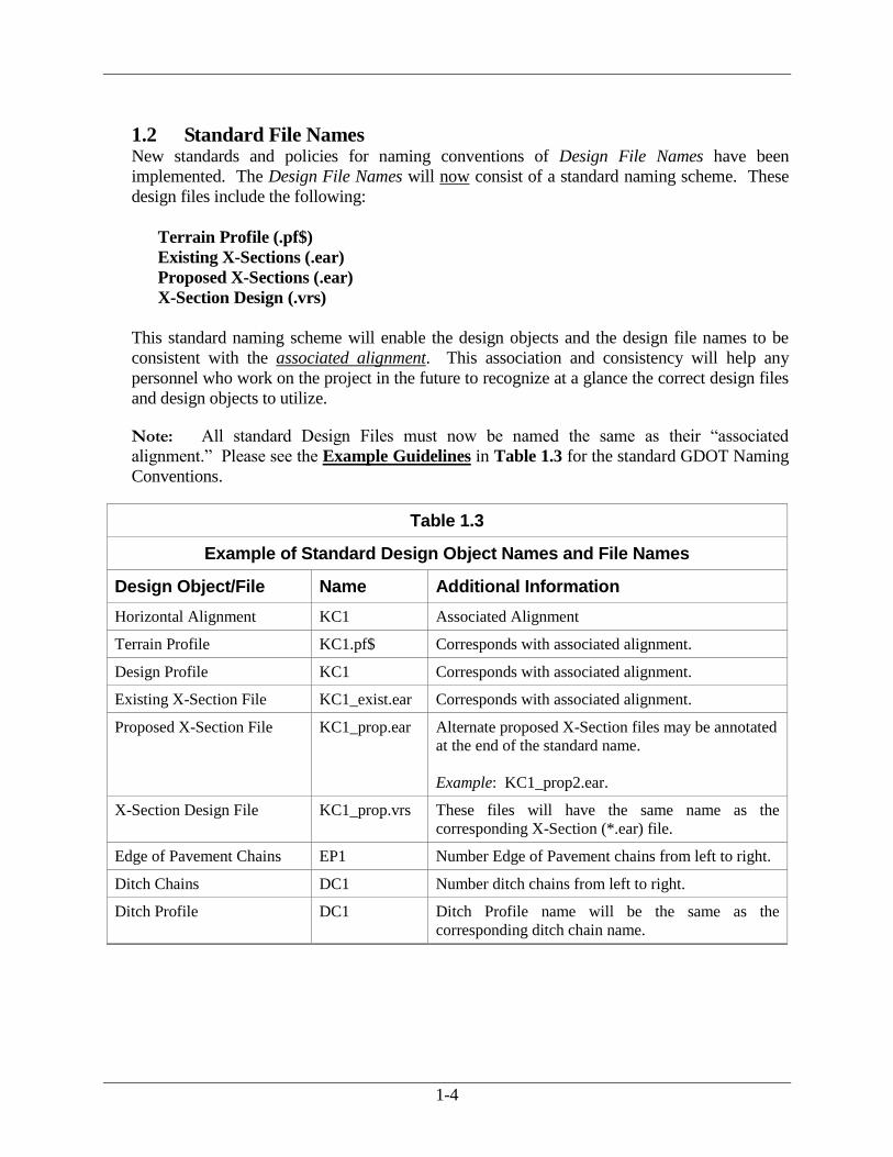
1.2 Standard File Names New standards and policies for naming conventions of Design File Names have been
implemented. The Design File Names will now consist of a standard naming scheme. These
design files include the following:
Terrain Profile (.pf$)
Existing X-Sections (.ear)
Proposed X-Sections (.ear)
X-Section Design (.vrs)
This standard naming scheme will enable the design objects and the design file names to be
consistent with the associated alignment. This association and consistency will help any
personnel who work on the project in the future to recognize at a glance the correct design files
and design objects to utilize.
Note: All standard Design Files must now be named the same as their “associated
alignment.” Please see the Example Guidelines in Table 1.3 for the standard GDOT Naming
Conventions.
Table 1.3
Example of Standard Design Object Names and File Names
Design Object/File Name Additional Information
Horizontal Alignment KC1 Associated Alignment
Terrain Profile KC1.pf$ Corresponds with associated alignment.
Design Profile KC1 Corresponds with associated alignment.
Existing X-Section File KC1_exist.ear Corresponds with associated alignment.
Proposed X-Section File KC1_prop.ear Alternate proposed X-Section files may be annotated
at the end of the standard name.
Example: KC1_prop2.ear.
X-Section Design File KC1_prop.vrs These files will have the same name as the
corresponding X-Section (*.ear) file.
Edge of Pavement Chains EP1 Number Edge of Pavement chains from left to right.
Ditch Chains DC1 Number ditch chains from left to right.
Ditch Profile DC1 Ditch Profile name will be the same as the
corresponding ditch chain name.

1-5
1.3 Standard R/W Point Cell Size and Text Size The feature table controls point cell size. It is only necessary to have the correct feature code
assigned to the point (see Table 1.2) and the appropriate feature table attached (see Table 3.1)
to plot these points to the appropriate size for R/W plans.
Before exporting R/W data to a Microstation DGN file, the designer must set the text size for
the point names. The table below (see Table 1.4) lists the appropriate text size for all R/W and
easement points on R/W plans according to the sheet scale used. To set the point name text
size, click on the “Settings” pull-down menu on the main CAiCE screen. Then place your
cursor over “Object Display” and click on “Points” on the pop-up menu to open the “Point
Display Settings” dialog box – Settings >> Object Display >> Points. Change the “size” field
in the name column to the appropriate setting from the table below.
Table 1.4
Right of Way Point Text Size
English Metric
Scale 20 50 100 250 500
Text Size 3.0 7.5 15.0 1.0 2.0
Right of Way points will be displayed with the cells shown in the following illustration:
RWRM: Required R/W monument where offset change occurs
REQD: Required R/W intersection with property line
PESMT: Permanent construction easement
1-6
1.4 Project Data Sheet As indicated previously, a new naming standard for design objects and design files has been
implemented in order to be consistent with the associated alignment. This association and
uniformity will help enable any personnel who may inherit the project in latter stages to
identify the correct design files and design objects. As an additional aid, and for
documentation purposes, Project Data Sheet forms have been implemented. These Project
Data Sheets must be used to conform to current GDOT standard guidelines. These forms
shall be included in electronic format with all submissions of the electronic CAiCE
project archive file. All electronic documentation files shall be provided in a Microsoft
Word format and located in a Documentation sub-folder of the project directory.
There are two types of Project Data Sheet forms:
1.4.1 Project Data Sheet (Alignment and Associated Objects and Files)
This form will be utilized to document the horizontal alignment and any of its associated
objects and files. There are two versions of this form available: the Single Alignment (See
Figure 1-1) form and the Multiple Alignment (See Figure 1-2) form. The version utilized
is left to the user’s discretion.
1.4.2 Project Data Sheet (Required Right of Way Objects)
This form will be utilized to document each Parcel and its’ associated chains (R/W chains,
Easement chains, etc.). (See Figure 1-3)

1-7
Figure 1-1

1-8
Figure 1-2

1-9
Figure 1-3

1-10
1.5 Location of Project Data Sheet Forms The Project Data Sheet forms are available in electronic format and are available for download
from both the internal and external Web site.
1.5.1 Internal to GDOT
All GDOT standard forms can be downloaded internally from the GDOT “R.O.A.D.S.”
Homepage. To access the Internal GDOT “R.O.A.D.S.” Homepage, enter Internet Explorer
or Netscape. Go straight to the link at:
http://www.dot.ga.gov/doingbusiness/PoliciesManuals/roads/software/Pages/CAiCEDocumentation.aspx
● Select the appropriate Project Data Sheet(s) and Save it to the computer.
1.5.2 External to GDOT
All GDOT standard forms can be downloaded externally from the GDOT “R.O.A.D.S.”
Homepage. To access the External GDOT “R.O.A.D.S.” Homepage, enter Internet
Explorer or Netscape. Go straight to the link at:
http://www.dot.ga.gov/doingbusiness/PoliciesManuals/roads/software/Pages/CAiCEDocumentation.aspx
● Select the appropriate Project Data Sheet(s) and Save it to the computer.
2. CAiCE Original Survey Data Projects
CAiCE Original Survey Data Projects
2-1
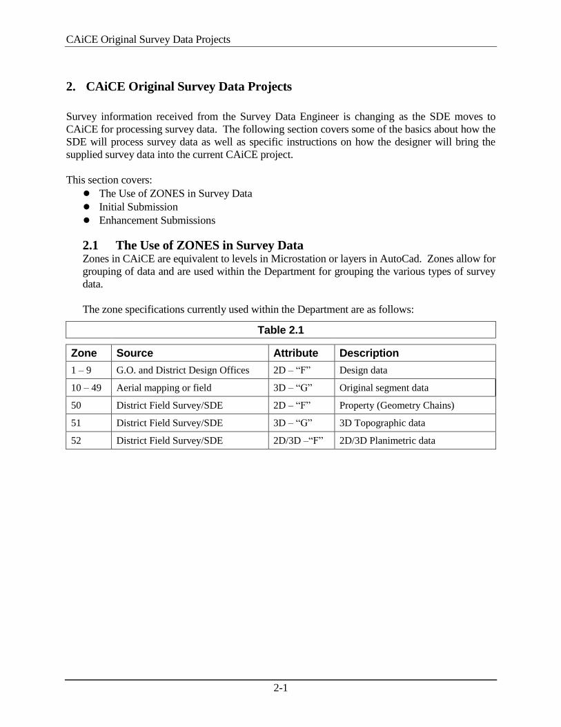
2. CAiCE Original Survey Data Projects
Survey information received from the Survey Data Engineer is changing as the SDE moves to
CAiCE for processing survey data. The following section covers some of the basics about how the
SDE will process survey data as well as specific instructions on how the designer will bring the
supplied survey data into the current CAiCE project.
This section covers:
● The Use of ZONES in Survey Data
● Initial Submission
● Enhancement Submissions
2.1 The Use of ZONES in Survey Data Zones in CAiCE are equivalent to levels in Microstation or layers in AutoCad. Zones allow for
grouping of data and are used within the Department for grouping the various types of survey
data.
The zone specifications currently used within the Department are as follows:
Table 2.1
Zone Source Attribute Description
1 – 9 G.O. and District Design Offices 2D – “F” Design data
10 – 49 Aerial mapping or field 3D – “G” Original segment data
50 District Field Survey/SDE 2D – “F” Property (Geometry Chains)
51 District Field Survey/SDE 3D – “G” 3D Topographic data
52 District Field Survey/SDE 2D/3D –“F” 2D/3D Planimetric data
2-2
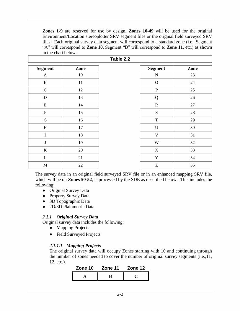
Zones 1-9 are reserved for use by design. Zones 10-49 will be used for the original
Environment/Location stereoplotter SRV segment files or the original field surveyed SRV
files. Each original survey data segment will correspond to a standard zone (i.e., Segment
“A” will correspond to Zone 10, Segment “B” will correspond to Zone 11, etc.) as shown
in the chart below.
Table 2.2
Segment Zone Segment Zone
A 10 N 23
B 11 O 24
C 12 P 25
D 13 Q 26
E 14 R 27
F 15 S 28
G 16 T 29
H 17 U 30
I 18 V 31
J 19 W 32
K 20 X 33
L 21 Y 34
M 22 Z 35
The survey data in an original field surveyed SRV file or in an enhanced mapping SRV file,
which will be on Zones 50-52, is processed by the SDE as described below. This includes the
following:
● Original Survey Data
● Property Survey Data
● 3D Topographic Data
● 2D/3D Plainmetric Data
2.1.1 Original Survey Data
Original survey data includes the following:
● Mapping Projects
● Field Surveyed Projects
2.1.1.1 Mapping Projects
The original survey data will occupy Zones starting with 10 and continuing through
the number of zones needed to cover the number of original survey segments (i.e.,11,
12, etc.).
Zone 10 Zone 11 Zone 12
A B C

2-3
2.1.1.2 Field Surveyed Projects
The original survey data will occupy Zones 51 – 52 (See 3D Topographic Data and
2D/3D Planimetric Data below) and will be moved to the correct segment zone by the
SDE which will typically be Segment “A” or Zone 10.
2.1.2 Property Survey Data
Property points will come in from the field in the field enhanced SRV file or in the original
field surveyed SRV file on Zone 50. These will be 2D (“F”) points that define any
property corners found, property points on line, etc.
2.1.3 3D Topographic Data
Data that will go to the DTM will come in from the field in the enhanced survey file or in
the original field surveyed SRV file on Zone 51. This data will be moved to the correct
segment zone by the SDE.
2.1.4 2D/3D Planimetric Data
Data that has an attribute of “F” (other than property data) that will come in from the field
in the enhanced survey file or in the original field surveyed SRV file will go to Zone 52.
This data will be moved to the correct segment zone by the SDE.

2-4
2.2 Initial Submission For the initial submission, the SDE will be supplying design with an archive file (.ZIP) of the
project with all the survey data imported, the DTM built, and the project ready to begin design.
The designer will:
● Create the Project in CAiCE
● Unarchive the Archive File
2.2.1 Create the Project in CAiCE
Follow the steps below to create the project in CAiCE:
1. From the CAiCE main pull-down menu, click File >> Project Manager and the CAiCE
Project Management System dialog appears as shown in Figure 2-1.
Figure 2-1

2-5
From the CAiCE Project Management System window, click Project >> Create and the Create
CAiCE Project dialog (shown in Figure 2-2) appears:
Figure 2-2
Note: All project names in CAiCE will be the P.I. Number of the project. For projects
with new TPRO project numbers, the CAiCE project name will be the last six digits of the
TPRO project number (i.e., TPRO project number = 0001234 so CAiCE project name =
001234).
2. In the Create CAiCE Project dialog, enter the following:
● Project Name
● Description
● Max No of Points (500000)
● Max No of Chains (250000)
● Project Unit
● Project Location (KCDATA directory)**
** Please note that all projects must be created in the KCDATA folder under the same
root drive in which CAiCE is located. If there is no KCDATA folder, the user
must create one.
Example: C:\KCDATA\

2-6
3. Click OK and the System Settings dialog appears as shown in Figure 2-3.
Figure 2-3
4. Set the System Settings as desired, then click OK to save entries.
2.2.2 Unarchive the Archive File
Follow the steps below to unarchive the archive file:
1. From the CAiCE main pull-down menu, click File >> Project Manager and the CAiCE
Project Management System dialog appears as shown in Figure 2-1.
2. From the CAiCE Project Management System window, click Project >> Unarchive.
Note: There will be a folder called SDE located in the project directory. This directory
will contain all files sent to the designer by the SDE besides CAiCE files (.DGN, etc.).

2-7
2.3 Enhancement Submissions Enhancement submissions include the following:
● Topo Enhancements
● Property Enhancements
2.3.1 Topo Enhancements
All enhanced topo data will be submitted in the form of SRV file(s) for the segment(s)
enhanced. The SRV file is to be a new, completely enhanced SRV Segment File. A
compressed file containing the new and revised DTM will also be submitted.
Follow the procedure below to incorporate the SRV file and revised DTM into the project
database:
● Invoke the GDOT Macro Menu
● Delete the Existing Survey Points and Chains by ZONE
● Reset the Point and Chain Prefixes
● Import the SRV File
● Update the DTM Surface

2-8
2.3.1.1 Invoke the GDOT Macro Menu
Follow the steps below to invoke the GDOT macro menu:
1. From the CAiCE main pull-down menu, click Tools >> Custom Tools >> GDOT
Macro Menu and the GDOT Macro Main Menu appears.
2. Click the Utilities tab, then click Addl. Survey Info to load the Additional Survey
Info Macro as shown in Figure 2-4.
Figure 2-4

2-9
2.3.1.2 Delete the Existing Survey Points and Chains by ZONE
Follow the steps below to delete existing survey points and chains by ZONE:
1. On the GDOT Additional Survey Info Macro dialog, click the TOPO check box.
2. Select the zone in the pull-down on the GDOT Additional Survey Info Macro.
3. Click Delete Survey Points and Chains.
4. Select the zone for deleting existing points and survey chains, then click OK.
2.3.1.3 Reset the Point and Chain Prefixes
Follow the steps below to reset the point and chain prefixes:
1. From the GDOT Additional Survey Info Macro dialog, click Reset Point and Chain
Prefixes and the Edit Database Prefixes dialog appears as shown in Figure 2-5.
Figure 2-5
2. In the Survey section, click Point.
3. Click Recompute, then click Update.
Note: To reset the SVXO prefix for both points and chains you MUST MANUALLY KEY
IN “1” for the Next Available Number field, then click Update.
4. In the Survey section, click Chain.
5. Click Recompute, then click Update.
6. Click Close to exit the dialog box.
2-10
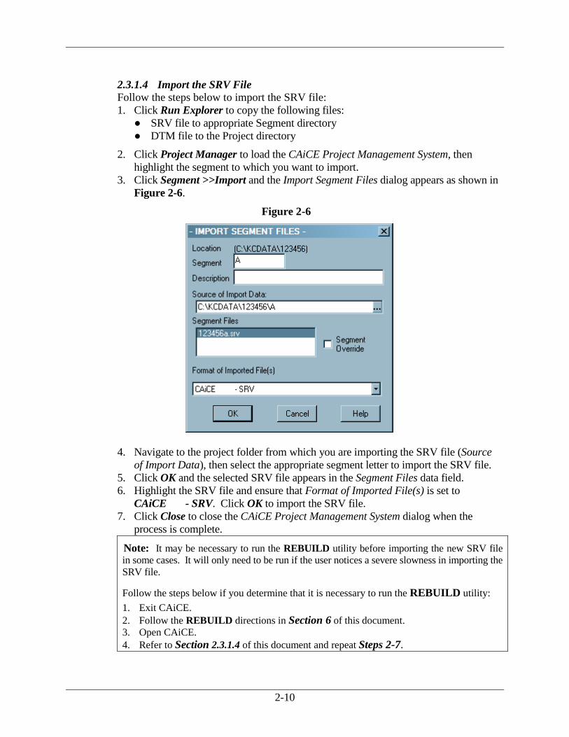
2.3.1.4 Import the SRV File
Follow the steps below to import the SRV file:
1. Click Run Explorer to copy the following files:
● SRV file to appropriate Segment directory
● DTM file to the Project directory
2. Click Project Manager to load the CAiCE Project Management System, then
highlight the segment to which you want to import.
3. Click Segment >>Import and the Import Segment Files dialog appears as shown in
Figure 2-6.
Figure 2-6
4. Navigate to the project folder from which you are importing the SRV file (Source
of Import Data), then select the appropriate segment letter to import the SRV file.
5. Click OK and the selected SRV file appears in the Segment Files data field.
6. Highlight the SRV file and ensure that Format of Imported File(s) is set to
CAiCE - SRV. Click OK to import the SRV file.
7. Click Close to close the CAiCE Project Management System dialog when the
process is complete.
Note: It may be necessary to run the REBUILD utility before importing the new SRV file
in some cases. It will only need to be run if the user notices a severe slowness in importing the
SRV file.
Follow the steps below if you determine that it is necessary to run the REBUILD utility:
1. Exit CAiCE.
2. Follow the REBUILD directions in Section 6 of this document.
3. Open CAiCE.
4. Refer to Section 2.3.1.4 of this document and repeat Steps 2-7.

2-11
2.3.1.5 Update the DTM Surface
Follow the steps below to update the DTM surface:
1. Click Delete DTM Dbase and the DTM Database Manager dialog appears.
2. Select EXIST surface and click Delete.
3. Click Close to close the dialog box.
4. Click Extract DTM to extract the compressed .ZIP file. When the Extract DTM
button is clicked, a brief DOS box may appear listing the extracted files. Then the
following message box will be depicted:
Note: The DTM is now provided in a ZIP file format! This Macro will only extract
DTM’s that are ZIP files. If the provided file is in LZH format, the macro will not work!
5. Click Create DTM Dbase to display the DTM Database Manager dialog and create
EXIST surface (new DTM data should automatically load into new EXIST surface).
6. Click Close to close the DTM Database Manager dialog when the process is
complete.
2.3.2 Property Enhancements
All property enhancements will come to the designer in the form of CAiCE .KCM files.
For property enhancements, the designer will receive ONE .KCM file from the SDE.
This .KCM file includes the original property information AND any property that has been
added or revised. The designer will then follow these steps to import the .KCM file into
the CAiCE database and update the property information.
Follow the procedure below to incorporate the .KCM file into the project database.
1. Follow Steps 1-2 in Section 2.3.1 “Topo Enhancements” to load the GDOT Additional
Survey Info Macro.
2. Click the PROPERTY check box, then click Database Explorer to load the Database
Explorer dialog.
3. Click Read All KCM Data Now.
4. Select the property .KCM file, then click Open to read the .KCM file into the project
database.
5. Conflicts are expected to occur due to the following conditions:
● The existing project already contains property data
● The .KCM file contains some of the same property data
2-12
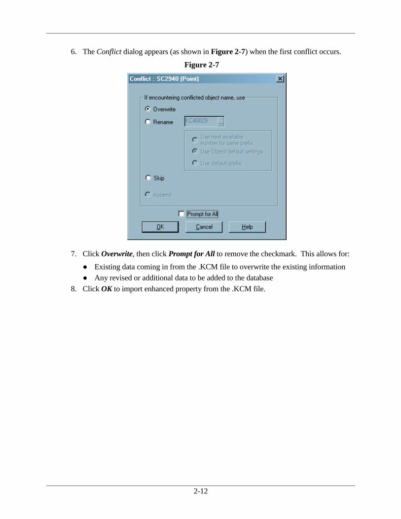
6. The Conflict dialog appears (as shown in Figure 2-7) when the first conflict occurs.
Figure 2-7
7. Click Overwrite, then click Prompt for All to remove the checkmark. This allows for:
● Existing data coming in from the .KCM file to overwrite the existing information
● Any revised or additional data to be added to the database
8. Click OK to import enhanced property from the .KCM file.
3. Standard GDOT Files
Standard GDOT Files
3-1
3. Standard GDOT Files
This section provides an overview of GDOT standard files and locations. Topics include the
following:
● Feature Tables
● Other Standard Files
● Location of Standard Files
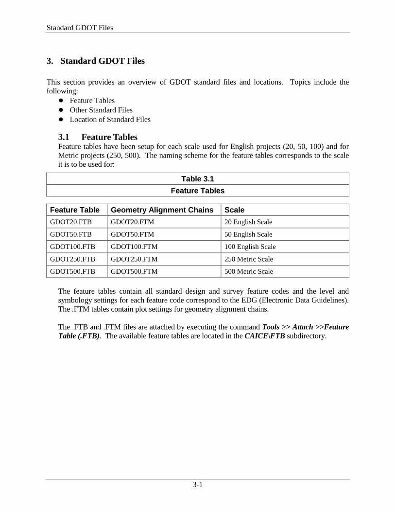
3.1 Feature Tables Feature tables have been setup for each scale used for English projects (20, 50, 100) and for
Metric projects (250, 500). The naming scheme for the feature tables corresponds to the scale
it is to be used for:
Table 3.1
Feature Tables
Feature Table Geometry Alignment Chains Scale
GDOT20.FTB GDOT20.FTM 20 English Scale
GDOT50.FTB GDOT50.FTM 50 English Scale
GDOT100.FTB GDOT100.FTM 100 English Scale
GDOT250.FTB GDOT250.FTM 250 Metric Scale
GDOT500.FTB GDOT500.FTM 500 Metric Scale
The feature tables contain all standard design and survey feature codes and the level and
symbology settings for each feature code correspond to the EDG (Electronic Data Guidelines).
The .FTM tables contain plot settings for geometry alignment chains.
The .FTB and .FTM files are attached by executing the command Tools >> Attach >>Feature
Table (.FTB). The available feature tables are located in the CAICE\FTB subdirectory.

3-2
3.2 Other Standard Files The following table (Table 3.2) lists other standard GDOT files and provides a brief
description of each one:
Table 3.2
File Description Comments
Cell Files The two (2) CAiCE cell files are the same
exact cell libraries used in Microstation
since CAiCE allows a direct translation of
a Microstation cell library (.CEL) into a
CAiCE cell library (.CCL).
The following is a list of the two cell files:
SDE.CCL English units
cell library
SDEM.CCL Metric units
cell library
These files reside in the
following subdirectory:
CAICE\CELL
These files are attached by the
following command:
Tools >> Attach >> Cell File
Earthwork Class Table The earthwork class table has been setup to
agree with the fragments that have also
been developed so that correct earthwork
will be computed. At the current time, the
only computations will be the amount of
“soil” for unclassified excavation and
embankment quantities. Later, pavement
layers, etc. may be added. The only
surface names that GDOT uses are EXIST
and SUB for the actual earthwork
computations. The fragment diagrams
reflect the surface names. The earthwork
class table is:
GDOTERWK.TBL
This file MUST be used to
obtain the correct earthwork
quantities.
This file resides in the
following subdirectory:
CAiCE\EWCLASS
The following command is
used to attached the file:
Tools >> Attach >>
Earthwork Class Table
Command Table The standard command table to attach is
the CAiCE – supplied command table
listed below:
DEFAULT.CTB
This file resides in the
following subdirectory:
CAiCE\COMMAND
This file is attached by
executing the following
command sequence:
Tools >> Attach >>
Command Table

3-3
Table 3.2
File Description Comments
INI Files The standard CAiCE INI files that have
been developed for creating projects are
listed below:
CAiCEe.ini English
CAiCEm.ini Metric
Standard INI files have also
been developed for plotting
cross-section sheets and profile
sheets (see Section 5 – Plan
Production)
Fragments The standard GDOT Fragment Description
files are located on the GDOT Macro Main
Menu.
To access Description files:
Select command
Tools>>Custom
Tools>>GDOT Macro
Menu to display the GDOT
Macro Main Menu form.
Click the File tab.
Click Fragment
Descriptions to load the
Fragment Descriptions
macro.
Microstation Seed Files When exporting CAiCE elements to
Microstation design files the following
standard Microstation seed files should be
used:
Plan View
Elements
GDOT2D.dgn (English)
GDOT2Dm.dgn (Metric)
Profile View
Elements
See Table 5.2
Cross-Section
View
Elements
See Table 5.4
Seed files reside in the
following directory:
CAiCE/Seed

3-4
3.3 Location of Standard Files This section discusses the location of standard files. Topics include files that are:
● Internal to GDOT
● External to GDOT
3.3.1 Internal to GDOT
All GDOT standard CAiCE files can be downloaded internally from the GDOT
“R.O.A.D.S.” Homepage.
Follow the Link below to access the Internal GDOT “R.O.A.D.S.” Homepage:
http://www.dot.ga.gov/doingbusiness/PoliciesManuals/roads/software/Pages/CAiCEStandard.aspx
A file called CAICEALL.EXE is available that allows you to update all of the CAiCE
standard files with one file. Download the file, execute it and specify the root drive of the
CAiCE directory (default is C:\) and the files will be updated. This file is updated
frequently. It is advisable to check the Web site weekly for the latest revisions. The latest
revisions can be viewed by clicking on the “CAiCEALL History (Brief)” link, but a
complete history of all revisions to the standard files can be viewed by clicking on the
“CAICEALL History (Full)” link on the download page.

3-5
3.3.2 External to GDOT
All GDOT standard CAiCE files can be downloaded externally from the GDOT
“R.O.A.D.S.” Homepage.
Follow the Link below to access the Internal GDOT “R.O.A.D.S.” Homepage: http://www.dot.ga.gov/doingbusiness/PoliciesManuals/roads/software/Pages/CAiCEStandard.aspx
A file called CAICEALL.EXE is available that allows you to update all of the CAiCE
standard files with one file. Download the file, execute it and specify the root drive of the
CAiCE directory (default is C:\) and the files will be updated. This file is updated
frequently. It is advisable to check the Web site weekly for the latest revisions. The latest
revisions can be viewed by clicking on the “CAiCEALL History (Brief)” link, but a
complete history of all revisions to the standard files can be viewed by clicking on the
“CAICEALL History (Full)” link on the download page.

4. Project Archival
Project Archival
4-1
4. Project Archival
CAiCE Visual Transportation 10 supports the .ZIP file format for its’ archival process. This
archival format was introduced with the advent of Visual 2000 (June 2000). CAiCE Visual
Transportation 10 still supports the old CAiCE archive file format for projects created prior to
Visual 2000 that utilized the .ARC and .DSN archive format.
It is recommended that the designer should make periodic archives of the project dataset to protect
against losing data if the database becomes corrupt. The designer should also make an archive
before performing any major process on the dataset, such as a REBUILD (see Section 6) or a
survey data update (see Section 2.3).
This section covers the project archival process, which includes the following topics:
● Opening the CAiCE Project Archive Utility
● Archiving the Project
4-2
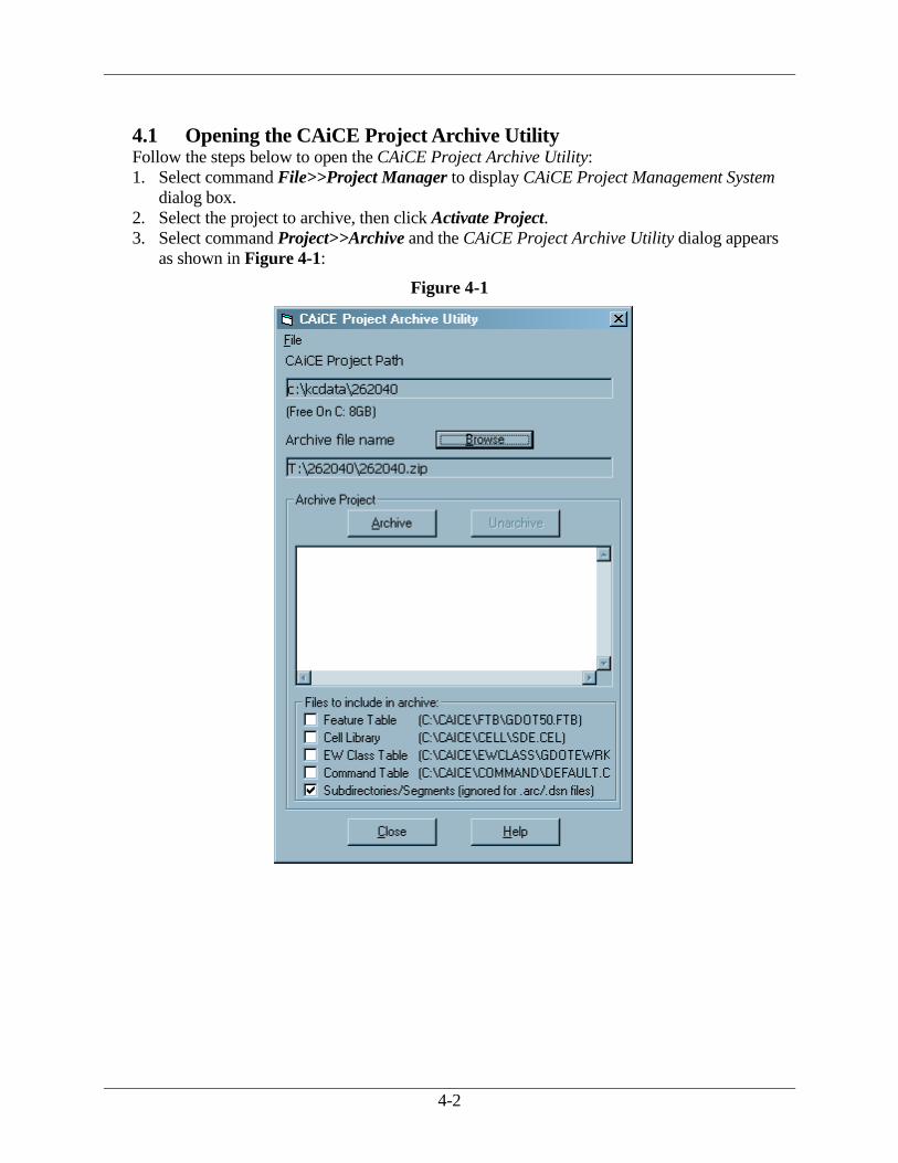
4.1 Opening the CAiCE Project Archive Utility Follow the steps below to open the CAiCE Project Archive Utility:
1. Select command File>>Project Manager to display CAiCE Project Management System
dialog box.
2. Select the project to archive, then click Activate Project.
3. Select command Project>>Archive and the CAiCE Project Archive Utility dialog appears
as shown in Figure 4-1:
Figure 4-1

4-3
4.2 Archiving the Project Follow the steps below to archive the current project:
1. Click Browse to select the archive location (Ex. Design Group Network Share).
Note: If you archive to the project directory, move the archive to a new location BEFORE
archiving the project again. If you are archiving to a folder which already contains a CAiCE
archive file, the new archive file must have a name which is DIFFERENT than any existing
archive files in the folder. The best practice is to change the existing archive file name in
Windows Explorer BEFORE creating a new archive. For example, a date could be appended to
the existing archive file name: original archive file name = 123456.zip; change archive file
name to 123456(5-28-03).zip in Windows Explorer before creating the new archive.
2. In the Files to include in archive section of this dialog, check the Subdirectories/Segments
checkbox. Do not check any of the other boxes!
3. Click Archive to archive project.
4. Click OK when the Archive Complete dialog appears.
5. Once the archive is complete, click Close to exit the CAiCE Project Archive Utility (shown
in Figure 4-2).
Figure 4-2

4-4
Select No when prompted by the dialog (shown in Figure 4-3).
Figure 4-3
6. Click Close to exit the CAiCE Project Management System and return to CAiCE.

5. Plan Production

Plan Production
5-1
5. Plan Production
This section covers the process for producing required plan sheets from the CAiCE database.
Topics include the following:
● Plan Sheet Elements
● Profile Sheets
● Cross-Section Sheets
5.1 Plan Sheet Elements Plan sheet elements contain the following components:
● Plot Settings
● Plan Sheets
● Construction Limits
5.1.1 Plot Settings
The designer shall manually set the following plan sheet elements:
● Font
● Degree Symbol
5.1.1.1 Font
Follow the steps below to set the plan sheet font:
1. Click Settings>> Global Options.
2. Click the Text tab and the Global Options dialog appears as shown in Figure 5-1.
Figure 5-1
3. Set Text Font =24, then click OK.

5-2
5.1.1.2 Degree Symbol
Follow the steps below to set the plan degree symbol:
1. Click Settings>>Special Characters and the Special Character Settings dialog
appears as shown in Figure 5-2.
Figure 5-2
2. Set Degree ASCII Value = 94, then click OK.
Note: The degree symbol will display as a “^” character in CAiCE and change to the correct
degree symbol when exported to Microstation.

5-3
5.1.2 Plan Sheets
Plan sheets are produced and plotted in Microstation. Clip borders for clipping the plan
sheets are placed along the alignment in Microstation. CAiCE allows the user to place clip
borders in CAiCE.
Follow the steps below for the placement of clip borders before the data is exported to
Microstation:
1. Click Drafting >>Store Sheet Windows Along Alignment and the dialog appears as
shown in Figure 5-3.
Figure 5-3
2. Complete the following values:
● % Overlap
● Store Prefix
● Feature Code (PLCLIP is the standard feature code to use)
3. Click Store (as shown in Figure 5-4) to store the objects in the database.
Figure 5-4

5-4
4. Click Size and the Plan Sheet Window Size dialog appears (shown in Figure 5-5).
Figure 5-5
5. Type the size for the project units as follows:
● English = 30" X 20"
● Metric = 780mm X 560mm
6. Type the desired scale.
7. Click OK to save settings and close the dialog.

5-5
5.1.3 Construction Limits
Once the endarea has been constructed, the construction limits can then be viewed with the
“C” and “F” cells.
Follow the steps below to view construction limits:
1. Ensure the correct CAiCE cell file (SDE.CCL or SDEM.CCL) is attached.
2. Ensure the correct feature table (GDOT*.FTB) is attached.
3. Click View >> X-Sections >> Surface Limits and the dialog appears as shown in
Figure 5-6.
4. Match the settings shown in the dialog (see Figure 5-6).
Figure 5-6
The construction limits will be viewed as a dashed line with the “C” and “F” cells.
Note: The surface “SUB” must be the active surface selected in the dialog (see Figure 5-6) for
the correct construction limits.

5-6
5.2 Profile Sheets The production of standardized profile sheets has been automated by the VBA macro Plot and
Export Profile Sheets. The user will also utilize the Plan Production Settings dialog box
(which can be accessed from the macro) to make the correct profile plotting settings.
The following are the steps necessary to produce profile sheets:
● Attach Files
● Run the VBA Macro
● Plans Production Settings
5.2.1 Attach Files
Follow the steps below to attach files needed to produce profile sheets:
1. Click Tools >> Attach >> Feature Table.
2. Select the appropriate feature table (see Table 5.1), then click Open.
3. Click Tools >> Attach >> Command Table.
4. Select default.ctb, then click Open.
5.2.2 Run the VBA Macro
Follow the steps below to run the VBA macro:
1. Click Tools >> Custom Tools >> GDOT Macro Menu and the GDOT Macro Main
Menu form appears.
2. Click the Plotting tab.
3. Click Plot and Export Profile Sheets and the Plot and Export Profile Sheets form
appears.
4. Click Help and the on-line .PDF Help description form for the macro appears.
5.2.3 Plans Production Settings
Use the Plans Production Settings dialog box (which can be accessed from the GDOT
Macro referenced in Section 5.2.2) to make sheet format selections
Follow the steps below to access plans production settings:
1. Click Plans Production Settings in the macro and the Plan Production Settings dialog
appears.
2. Select PROFILE from the Drawing Type pull-down list.
3. Select the desired scale from the Sheet Scale pull-down list.
Note: Currently, the only option available for Sheet Size is FULL
4. Accept all other default settings.
5. Click OK to close dialog box and activate the correct settings.
Note: When you click Export to Microstation on the Plot and Export Profile Sheets macro
form, the applicable seed file (see Table 5.2) is used to create the profile .DGN file and the
applicable reference grid file (see Table 5.3) is copied to the CAiCE project directory.
5-7
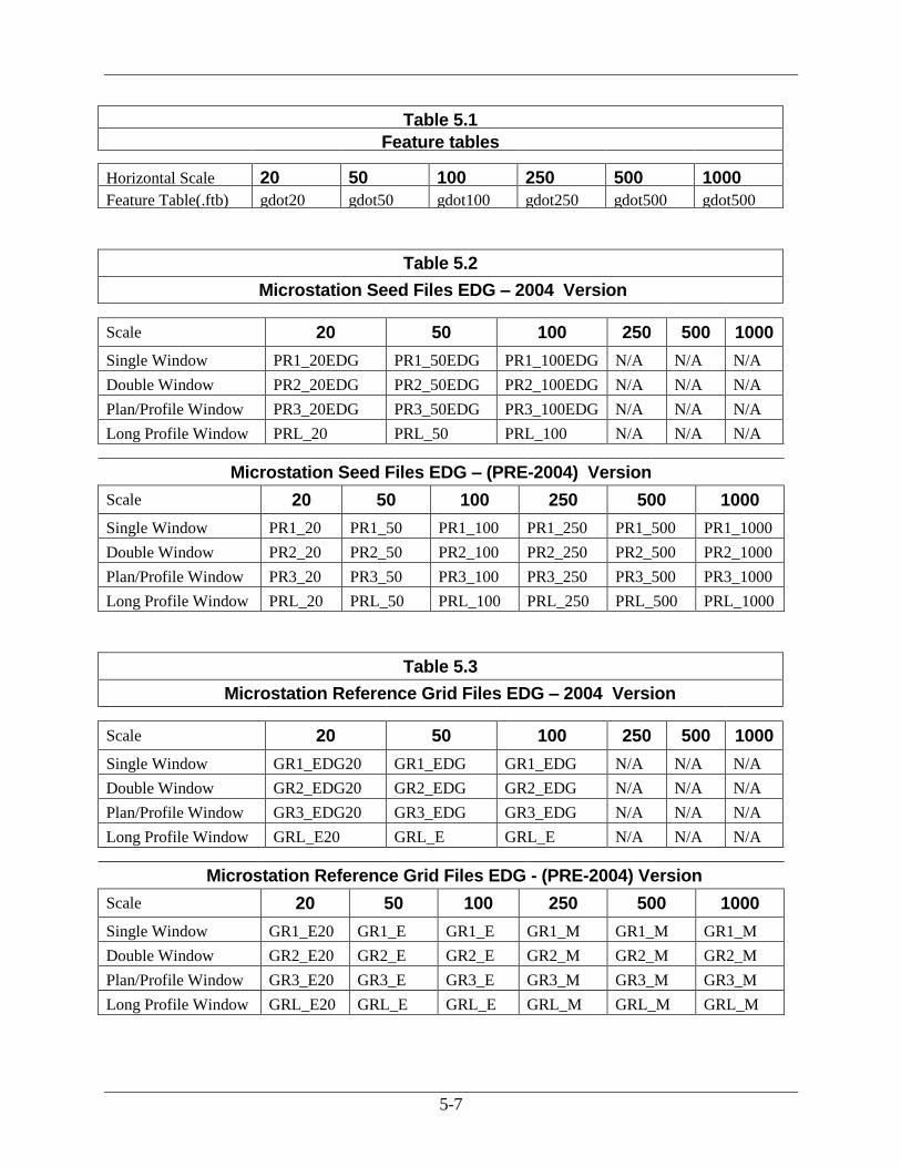
Table 5.1
Feature tables
Horizontal Scale 20 50 100 250 500 1000
Feature Table(.ftb) gdot20 gdot50 gdot100 gdot250 gdot500 gdot500
Table 5.2
Microstation Seed Files EDG – 2004 Version
Scale 20 50 100 250 500 1000
Single Window PR1_20EDG PR1_50EDG PR1_100EDG N/A N/A N/A
Double Window PR2_20EDG PR2_50EDG PR2_100EDG N/A N/A N/A
Plan/Profile Window PR3_20EDG PR3_50EDG PR3_100EDG N/A N/A N/A
Long Profile Window PRL_20 PRL_50 PRL_100 N/A N/A N/A
Microstation Seed Files EDG – (PRE-2004) Version
Scale 20 50 100 250 500 1000
Single Window PR1_20 PR1_50 PR1_100 PR1_250 PR1_500 PR1_1000
Double Window PR2_20 PR2_50 PR2_100 PR2_250 PR2_500 PR2_1000
Plan/Profile Window PR3_20 PR3_50 PR3_100 PR3_250 PR3_500 PR3_1000
Long Profile Window PRL_20 PRL_50 PRL_100 PRL_250 PRL_500 PRL_1000
Table 5.3
Microstation Reference Grid Files EDG – 2004 Version
Scale 20 50 100 250 500 1000
Single Window GR1_EDG20 GR1_EDG GR1_EDG N/A N/A N/A
Double Window GR2_EDG20 GR2_EDG GR2_EDG N/A N/A N/A
Plan/Profile Window GR3_EDG20 GR3_EDG GR3_EDG N/A N/A N/A
Long Profile Window GRL_E20 GRL_E GRL_E N/A N/A N/A
Microstation Reference Grid Files EDG - (PRE-2004) Version
Scale 20 50 100 250 500 1000
Single Window GR1_E20 GR1_E GR1_E GR1_M GR1_M GR1_M
Double Window GR2_E20 GR2_E GR2_E GR2_M GR2_M GR2_M
Plan/Profile Window GR3_E20 GR3_E GR3_E GR3_M GR3_M GR3_M
Long Profile Window GRL_E20 GRL_E GRL_E GRL_M GRL_M GRL_M

5-8
5.3 Cross-Section Sheets The production of standardized X-Section sheets is detailed in the steps below. A VBA macro
called Plot and Export X-Section Sheets (which automates several of the steps listed below) has
been created which assists in the “exportation” of X-Sections to MicroStation. This macro is
described in more detail in the next section.
The Plans Production Settings dialog box (shown in Figure 5-7) has been configured to assist
in the process of plotting standardized cross sections in CAiCE.
Figure 5-7
This tool allows you to make sheet format selections from drop-down lists to plot English or
Metric cross sections. These sheet format selections will include options for plotting cross
sections on narrow or wide sheets at a particular scale. This tool also includes the options of
choosing the Drawing Type to conform to the Border Size of the EDG (Electronic Data
Guidelines). The EDG options are EDG - 2004 standards or the EDG – (Pre-2004) standards.
This section covers the following topics:
● Sheet Format Selections
● View Cross Sections
● Export Cross Sections to MicroStation
● Copy the MicroStation Reference Grid File
● VBA macro Plot and Export X-Section Sheets
5.3.1 Sheet Format Selections
Follow the steps below to make sheet format selections using the Plans Production Settings
dialog:
1. Click Settings >> Sheet Formats >> Plans Production and the Plans Production
Settings dialog appears as shown in Figure 5-7.
2. From the Drawing Type drop-down list, select one of the following options:
● XSEC-NARROW-EDG (EDG - 2004 Format)
● XSEC-NARROW (EDG - Pre-2004 Format)
● XSEC-WIDE-EDG (EDG - 2004 Format)
● XSEC-WIDE (EDG - Pre-2004 Format)
5-9
3. Select the desired scale from Sheet Scale drop-down list.
Note: Currently, the only option available for Sheet Size is FULL
4. Click OK to close the dialog and activate the correct settings.
5.3.2 View Cross Sections
The following steps are required for you to view cross sections:
● Clear the Screen
● Attach the Feature Table
● View X-Section on Sheets Dialog Settings
● Check Surface Features to View
● View Graphic Extents
5.3.2.1 Clear the Screen
You must first clear the screen graphics before you view the cross sections. Press the
<F8> key to clear the screen graphics.
5.3.2.2 Attach the Feature Table
Follow the steps below to attach the feature table:
1. Click Tools >>Attach>> Feature Table (.FTB).
2. Select the appropriate feature table (see Table 5.4) and click Open.
5.3.2.3 View X-Section on Sheets Dialog Settings
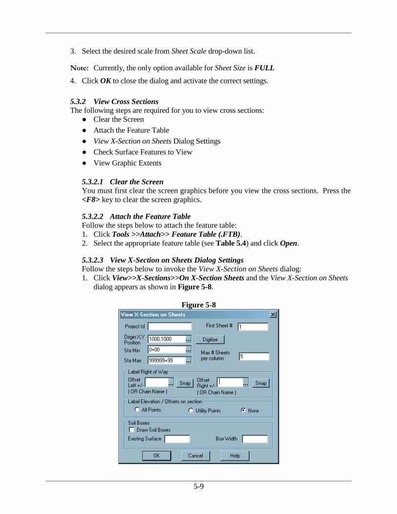
Follow the steps below to invoke the View X-Section on Sheets dialog:
1. Click View>>X-Sections>>On X-Section Sheets and the View X-Section on Sheets
dialog appears as shown in Figure 5-8.
Figure 5-8
5-10
2. Enter values in the dialog fields as follows:
Field Value
Origin X,Y Position 1000, 1000
Max # Sheets per column 5
Sta Min Type the value for the first station to be plotted
Sta Max Type the value for the last station to be plotted
3. Click OK to close the dialog and save values.
Note: Entire cross section file will be plotted if you use the following default values:
Sta Min = 0+00 and Sta Max = 999999+99
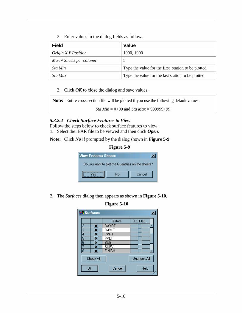
5.3.2.4 Check Surface Features to View
Follow the steps below to check surface features to view:
1. Select the .EAR file to be viewed and then click Open.
Note: Click No if prompted by the dialog shown in Figure 5-9.
Figure 5-9
2. The Surfaces dialog then appears as shown in Figure 5-10.
Figure 5-10
5-11
3. Ensure that an X appears to the left of each surface feature in the Feature column.
4. Click OK to view cross sections on screen.
5.3.2.5 View Graphic Extents
View graphic extents by pressing the <F6> key.
5.3.3 Export Cross Sections to MicroStation
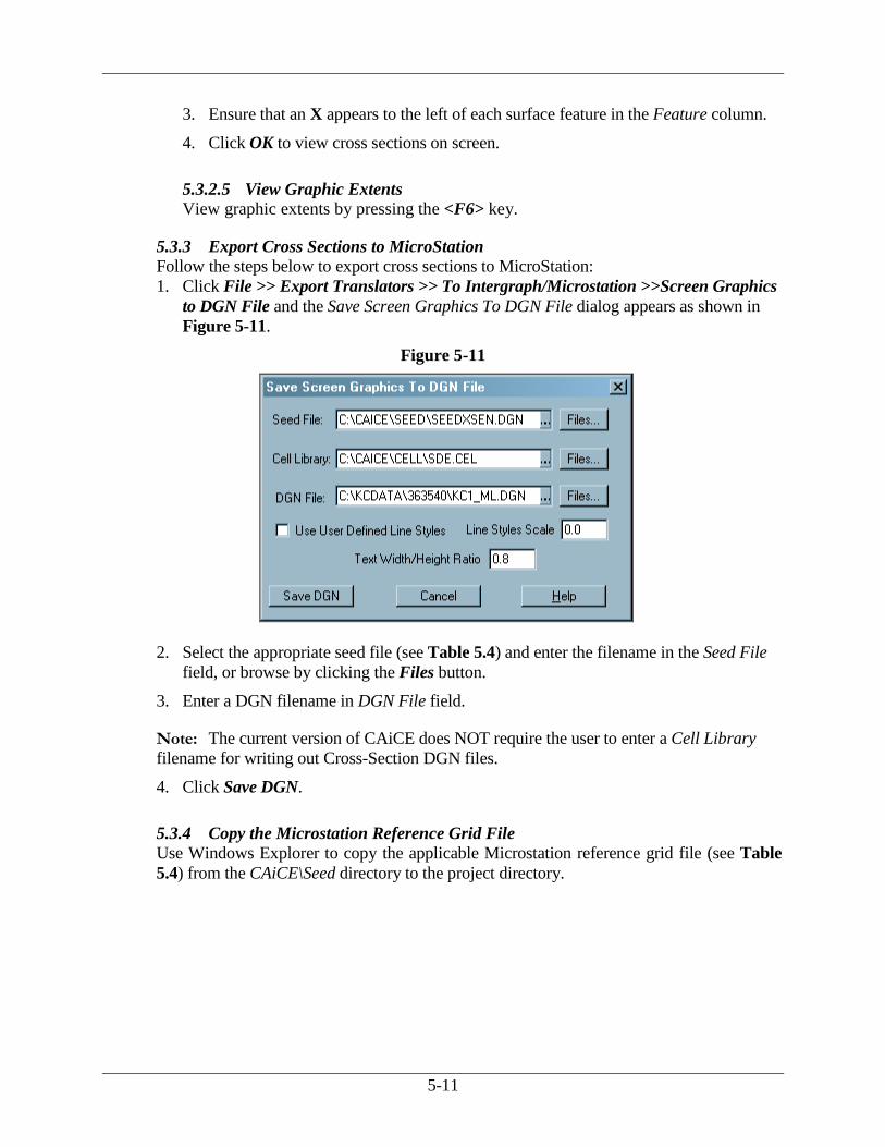
Follow the steps below to export cross sections to MicroStation:
1. Click File >> Export Translators >> To Intergraph/Microstation >>Screen Graphics
to DGN File and the Save Screen Graphics To DGN File dialog appears as shown in
Figure 5-11.
Figure 5-11
2. Select the appropriate seed file (see Table 5.4) and enter the filename in the Seed File
field, or browse by clicking the Files button.
3. Enter a DGN filename in DGN File field.
Note: The current version of CAiCE does NOT require the user to enter a Cell Library
filename for writing out Cross-Section DGN files.
4. Click Save DGN.
5.3.4 Copy the Microstation Reference Grid File
Use Windows Explorer to copy the applicable Microstation reference grid file (see Table
5.4) from the CAiCE\Seed directory to the project directory.

5-12
5.3.5 VBA Macro Plot and Export X-Section Sheets
Use the VBA Macro Plot and Export X-Section Sheets to automate the process of
generating X-Sections in CAiCE.
Follow the steps below to run the VBA macro:
1. Click Tools >> Custom Tools >> GDOT Macro Menu and the GDOT Macro Main
Menu form appears.
2. Click the Plotting tab.
3. Click Plot and Export X-Section Sheets and the Plot and Export X-Section Sheets form
appears.
4. Click Help and the on-line .PDF Help description form for the macro appears.
The Plot and Export X-Section Sheets macro automates the step by step process described in
Section 5.3.1 – Section 5.3.4. Follow the steps below to utilize the macro:
1. Select the EDG Version of EDG -2004 or EDG- (PRE-2004) – this option
determines the EDG Border Version.
2. Select the Sheet Type option of Narrow or Wide.
3. Click Plans Productions in the macro. The Plan Production Settings dialog box
appears. Select the appropriate Drawing Type which corresponds to the EDG
Version selected.
4. Click Plot to CAiCE Screen. Follow the prompts for viewing X-sections. (See the
previous Section 5.3.2 View Cross Sections for screen captures and details).
5. Click Export to MicroStation. The user will enter the desired name for the X-
Section DGN file. The macro will then automatically select the correct seed file to
use in creating the X-Section design file. The X-Section file along with the correct
reference grid file will be exported to the CAiCE Project directory.
Table 5.4
Feature Tables and Microstation Files
Units ENGLISH METRIC Sheet Layout Narrow Wide Narrow Wide
Feature Table Gdot50.ftb gdot50.ftb gdot500.ftb gdot500.ftb
EDG - 2004
Seed File SeedXSen-edg.dgn SeedXSew-edg.dgn Not Available Not Available
Ref. Grid File Kcgrden-edg.dgn Kcgrdew-edg.dgn Not Available Not Available
EDG - (PRE-2004)
Seed File
-2004
SeedXSen.dgn seedXSew.dgn seedXSmn.dgn seedXSmw.dgn
Ref. Grid File Kcgrden.dgn Kcgrdew.dgn Kcgrdmn.dgn Kcgrdmw.dgn

5-13
Note: You have the option to select one of the following cross
section sheet formats:
“EDG-2004” Format cross section sheets Figure 5-12
“EDG-(Pre-2004)” Format cross-section sheets
Figure 5-13
Figure 5-12: EDG-2004 Format
Cross Section Sheet
Figure 5-13: EDG - (Pre-2004) Format
Cross Section Sheet

6. Rebuild Utility
Rebuild Utility
6-1
6. Rebuild Utility
In some cases, the CAiCE database will need to be “rebuilt.” CAiCE provides a utility with the
installation that will rebuild the database files. One of the biggest signs of the database needing
rebuilding is unusual occurrences in the database, especially in viewing operations. The process
is run on three files: the .GO4, .PT4, and the .PS4 files. These files are the main database files
containing point, chain, and prefix information. The Standard GDOT Files must be downloaded
in order to perform this task (see Section 3.3).
Follow the steps below to run the REBUILD utility:
1. Exit CAiCE and go to the MS-DOS Prompt.
2. Go to the project directory.
3. Key-in: REB project (i.e., REB 123456, REB 621450, etc.)
4. Just press Enter as prompted until completed.
5. Re-enter CAiCE and things should be more stable.

7. Additional Files to be Produced

Additional Files to Be Produced
7-1
7. Additional Files to Be Produced
This section covers methods for compiling additional files to be produced using CAiCE. Topics
include the following:
● Write Data Out to a Data Collector
● Generate Deed Files
● Provide Files to Contractors
7.1 Write Data Out to a Data Collector To write out data to upload into a data collector to take back to the field, the Stakeout Survey
Data macro should be used. This method only writes out data in X and Y format.
Follow the steps below to write out the data:
1. Click Tools >> Custom Tools >> GDOT Macro Menu and the GDOT Macro Main Menu
form appears.
2. Click the File tab.
3. Click Stakeout Survey Data to load the Stakeout Survey Data macro (see Figure 7-1).
Figure 7-1
4. In the ASC File to create: field, define the name of the .ASC file to create, including the
.ASC extension. The full path may also be defined as well. The default location for the
saved file is the project directory.
5. Click Write Out Survey Data. The current project database is then read and the points
matching the following feature codes are obtained:
PAR, RWE, RWM, RWC, RWU, PCF, POEL
PPC, SNGSCM, SLCM, SLCD, SDCD, SBNCHMK
REQD, PESMT, TESMT, DWESMT, RWRM, CONSTCL, SIDECL
6. For each point, the prefix is stripped off, the point is checked for duplication, and then it is
written to the .ASC file. If any points are duplicated, the user receives a warning message.
7. Upon completion, the user is notified by message box and the file viewing buttons are
activated.

7-2
7.2 Generate Deed Files Once the Right-of-Way plans are approved, the “deed description files” containing the data
used for writing deeds may be generated with the GDOT KCRW macro.
Follow the steps below to access the GDOT KCRW macro:
1. Click Tools >> Custom Tools >> GDOT Macro Menu.
2. Click the Utilities tab.
3. Click KCRW and the GDOT KCRW Macro (RW/Deed Description) dialog appears as
shown in Figure 7-2.
Figure 7-2
4. Click Help to display the on-line help file for the macro.
7-3
7.3 Provide Files to Contractors When a project is complete and let to construction, alignments and other information will be
supplied to the Contractor. Four types of data will be provided:
● Alignment File Descriptions
● Alignment Report Files
● Endarea Report Files
● GPS Grading Report Files
NOTE:
The Alignment File Descriptions, Alignment Report Files, Endarea Report Files and the GPS
Grading Report Files will be provided Pre-Award of the Contract.
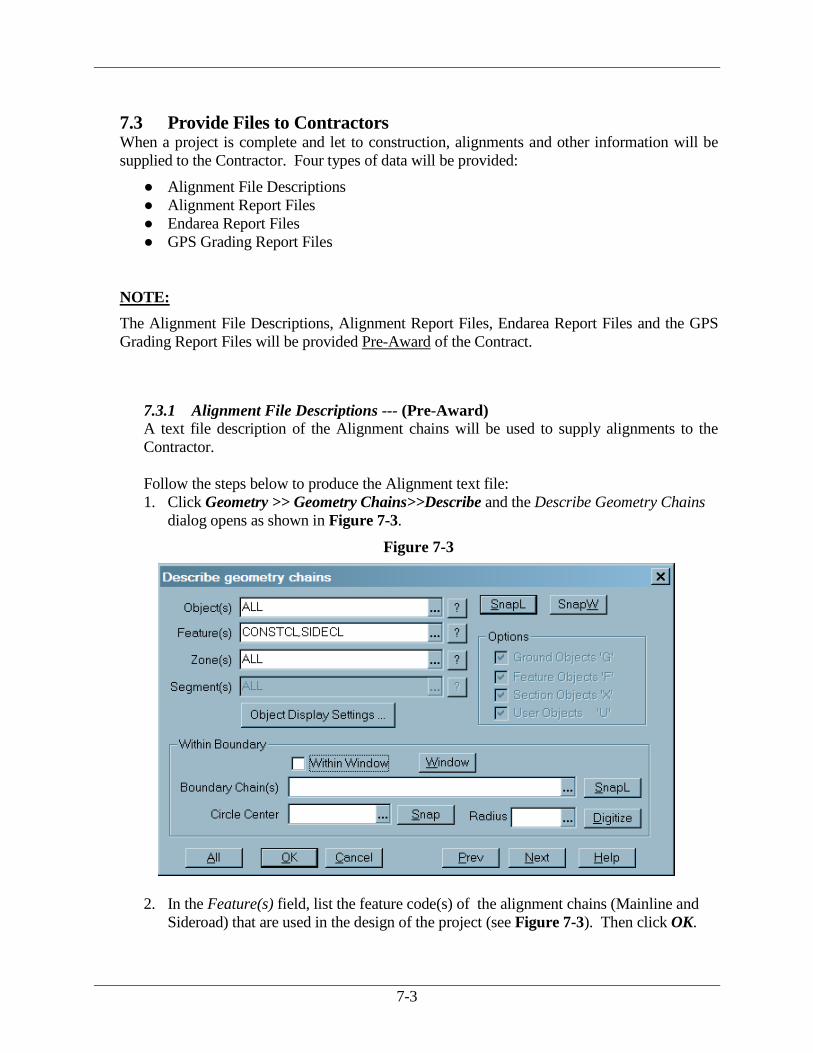
7.3.1 Alignment File Descriptions --- (Pre-Award)
A text file description of the Alignment chains will be used to supply alignments to the
Contractor.
Follow the steps below to produce the Alignment text file:
1. Click Geometry >> Geometry Chains>>Describe and the Describe Geometry Chains
dialog opens as shown in Figure 7-3.
Figure 7-3
2. In the Feature(s) field, list the feature code(s) of the alignment chains (Mainline and
Sideroad) that are used in the design of the project (see Figure 7-3). Then click OK.

7-4
Note: For the above procedure to work as documented, all alignments must have been stored in
CAiCE using the standard GDOT feature codes for alignments as shown below.
CONSTCL Construction Centerline
SIDECL Sideroad Centerline
3. This will open the CAiCE default text editor which displays a description of the
selected Mainline and Sideroad alignment chains (see example Figure 7-4).
Figure 7-4
4. Save the alignment text file using the following naming scheme: PI#AL.txt (i.e.,
123456AL.txt).

7-5
7.3.2 Alignment Report Files --- (Pre-Award)
Alignment Report Files will be utilized to supply alignment chain information to the
Contractor for use in GPS equipment. This report depicts the alignment information
located at 50 Foot Station intervals at a Zero offset. This Report is required for each
CONSTCL and SIDECL alignment in the CAiCE Project. (Please Note: Each Alignment
input must be generated one alignment at a time).
Follow the steps below to produce the Alignment Report File:
1. Click Geometry >> Geometry Chains>>Stake Out>>Even Stations and the Chain
Stake Out Report dialog opens as shown in Figure 7-5.
Figure 7-5
2. In the Name of Chain field, list the name of the Alignment Chain (Mainline and/or
Sideroad) that is used in the design of the project (see Figure 7-5). Each Alignment
must be input separately – one alignment at a time per dialog box. Then make sure that
the Minimum, Maximum, Even Stations (50.00) and Offset Distance (0.00) correspond
to the screen capture depicted above. Then click OK.
Note: For the above procedure to work as documented, all alignments must have been stored in
CAiCE using the standard GDOT feature codes for alignments as shown below.
CONSTCL Construction Centerline
SIDECL Sideroad Centerline
3. This will open the CAiCE default text editor which displays a report description of the
selected Mainline/ Sideroad alignment chain input as the last entry in the text file.

7-6
4. The Alignment Chain is “appended” to the end of the PI#.RPT file (Ex. 123456.RPT)
report file. The user will need to type the Name of the Roadway next to the Chain
Name in the Header of the Report of the Alignment Chain (See example Figure 7-6).
Figure 7-6
Save the alignment text file using the following naming scheme:
projectnameAL_GPS.txt (i.e., 123456AL_GPS.txt).
5. Repeat Steps 1-4 for each CONSTCL and SIDECL in the CAiCE Project.
6. When all Alignments are represented in the Report File (appended at the end of the
RPT file) and all Road Names have been input in the associated Alignment --- next
copy, paste and then save all of these alignment entries into one new txt file using the
following naming scheme: PI#AL_GPS.txt (i.e., 123456AL_GPS.txt).
Please Note: DO NOT send the original PI#.RPT file (which contains all of the
CAiCE Project Description Information)… Please submit only the Alignment Report
Files appended at the bottom of the PI#.RPT report. The process for this is described in
Step 6.

7-7
7.3.3 Endarea Report Files --- (Pre-Award)
Endarea Report Files will be used to supply endarea information to the Contractor. To
generate the report files, use the GDOT Write Endarea File Macro which is part of the
standard CAICEALL.EXE download. (See Section 3.2 on Page 3-2 for location of
Standard Files). This macro reads a specified CAiCE Endarea (.EAR) file and produces a
GDOT Standard Format Output file. The standard format is documented in the macro help
description file.
Follow the steps below to run the GDOT Write Endarea File Macro:
1. Click Tools >> Custom Tools >> GDOT Macro Menu and the GDOT Macro Main
Menu form appears.
2. Click the File tab.
3. Click Write Endarea File to load the GDOT Write Endarea File Macro as shown in
Figure 7-7.
Figure 7-7
4. Click Help to display the on-line .PDF help description form for the macro.
5. The GDOT Write Endarea File Macro writes out a CAiCE Endarea file to a standard
GDOT ASCII text file for distribution to Contractors when a project is let to
Construction.
7-8
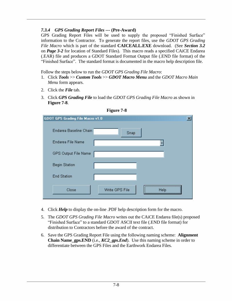
7.3.4 GPS Grading Report Files --- (Pre-Award)
GPS Grading Report Files will be used to supply the proposed “Finished Surface”
information to the Contractor. To generate the report files, use the GDOT GPS Grading
File Macro which is part of the standard CAICEALL.EXE download. (See Section 3.2
on Page 3-2 for location of Standard Files). This macro reads a specified CAiCE Endarea
(.EAR) file and produces a GDOT Standard Format Output file (.END file format) of the
“Finished Surface”. The standard format is documented in the macro help description file.
Follow the steps below to run the GDOT GPS Grading File Macro:
1. Click Tools >> Custom Tools >> GDOT Macro Menu and the GDOT Macro Main
Menu form appears.
2. Click the File tab.
3. Click GPS Grading File to load the GDOT GPS Grading File Macro as shown in
Figure 7-8.
Figure 7-8
4. Click Help to display the on-line .PDF help description form for the macro.
5. The GDOT GPS Grading File Macro writes out the CAiCE Endarea file(s) proposed
“Finished Surface” to a standard GDOT ASCII text file (.END file format) for
distribution to Contractors before the award of the contract.
6. Save the GPS Grading Report File using the following naming scheme: Alignment
Chain Name_gps.END (i.e., KC2_gps.End). Use this naming scheme in order to
differentiate between the GPS Files and the Earthwork Endarea Files.

8. Converting Projects from CEAL to CAiCE

Converting Projects from CEAL to CAiCE
8-1
8. Converting Projects from CEAL to CAiCE
Two situations will occur when converting CEAL Project files from CEAL to CAiCE. These
scenarios are as follows:
● The Survey Data will be Converted from CEAL to CAiCE
● The Design Data will be Converted from CEAL to CAiCE
8.1 The Survey Data will be Converted from CEAL to CAiCE ALL conversion of Survey Data from CEAL to CAiCE will be performed by the Office of
Environment/Location. The designer should contact the Engineering Management Group
Operation Manager of the Office of Environment/Location for details.
Upon completion of the Survey Data conversion process, the Office of Environment/Location
will submit to the designer a CAiCE archive (.ZIP) file of the project. The designer will then
proceed to the following steps.
Note: The designer should never perform any Survey Data conversion.
8.2 The DESIGN DATA will be Converted from CEAL to CAiCE The designer will have a CEAL INT file. The INT file will contain both the survey data the
SDE provided, as well as design data the designer has stored. The designer is concerned only
with the design data in the INT file.
The steps to convert the design data from CEAL to CAiCE are as follows:
● Write Interface File
● Create the Project in CAiCE
● Unarchive the CAiCE Archive File
● Import the INT File
8.2.1 Write Interface File
The designer will perform a WRITE Interface command from the most current CEAL
project database. This WRITE Interface will be to write out the design data to an INT file.
This resulting INT file will then be imported later into the CAiCE project database
submitted by the Office of Environment/Location.
Follow the steps below to write the interface file:
Use the WRITE Interface fname command in CEAL to write out the design data to an
INT file. This can be accomplished by:
● Using the standard class codes (CLASS REQD, etc.)
Example: Write Int fname CLASS REQD, etc.
● Using the prefix on all design data (SEL A*, etc.).
Example: Write Int fname SEL A000 to A999, R000 to R999

8-2
8.2.2 Create the Project in CAiCE.
Please see Section 2.2.1 on Page 2-4 of this document for details on how to create a
CAiCE Project and set System Settings.
8.2.3 Unarchive the CAiCE Archive File
Unarchive the project archive file received from the Office of Environment/Location into
the CAiCE project created in the previous step.
8.2.4 Import the INT file
Follow the steps below to import the INT file containing the design data into the CAiCE
project database:
1. Click File >> Import Translators >> From CEAL >> Geometry Interface File (INT)
and the Ceal INT – CAiCE Defaults dialog appears as shown in Figure 8-1.
Figure 8-1
2. Enter settings as shown in the following table:
Field Default Prefix Starting No.
Points KC 10000
Geometry Curves C -1
3. Leave all other Default Prefixes blank.
4. Leave all other Starting No.’s set to the defaults (see Figure 8-1).
5. Click OK.
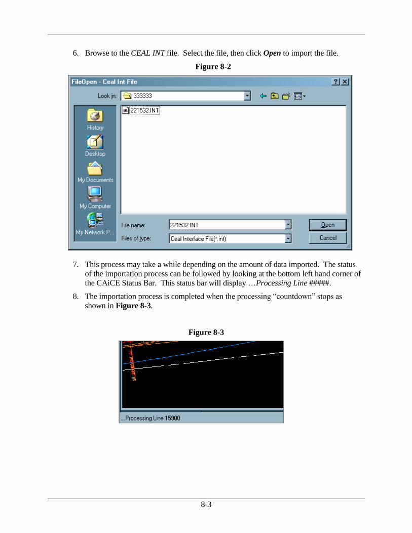
8-3
6. Browse to the CEAL INT file. Select the file, then click Open to import the file.
Figure 8-2
7. This process may take a while depending on the amount of data imported. The status
of the importation process can be followed by looking at the bottom left hand corner of
the CAiCE Status Bar. This status bar will display …Processing Line #####.
8. The importation process is completed when the processing “countdown” stops as
shown in Figure 8-3.
Figure 8-3

8-1
Appendix A Quick Reference Guide to Design Tables

Appendix A
A-1
APPENDIX A QUICK REFERENCE GUIDE TO DESIGN TABLES
Table 1.1
Design Object Names
Object Prefix Starting Number
Point* KC 10000 (Max. = 99999)
Curve KC 1
Spiral KC 1
Geometry Chain (Alignment) KC 1
Geometry Chain (Right of Way) KC User-defined**
Geometry Chain (Easement) KC User-defined**
Geometry Chain (Edge of pavement, travel
lane or paved shoulder)
EP 1
Geometry Chain (Shoulder hinge point) SH 1
Geometry Chain (Ditch CL) DC 1
Design Profile KC 1
Other User-defined User-defined
*All design points must be named with a prefix of KC and begin with the number 10000 (e.g., first
design point = KC10000).
**It is suggested that a block of chain numbers be set aside for Right-of-Way and Easement chains
before beginning to store these chains (e.g., R/W chain numbers = 101-300; Easement chain
numbers = 301-500).
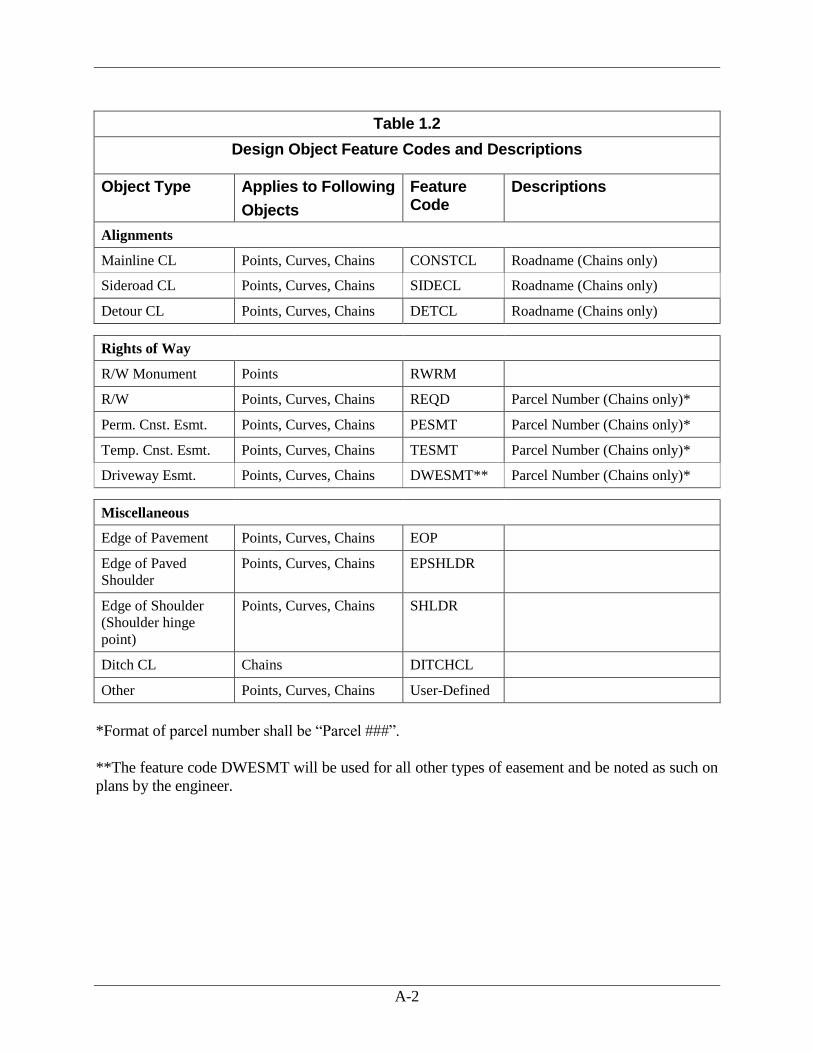
A-2
Table 1.2
Design Object Feature Codes and Descriptions
Object Type Applies to Following
Objects
Feature Code
Descriptions
Alignments
Mainline CL Points, Curves, Chains CONSTCL Roadname (Chains only)
Sideroad CL Points, Curves, Chains SIDECL Roadname (Chains only)
Detour CL Points, Curves, Chains DETCL Roadname (Chains only)
Rights of Way
R/W Monument Points RWRM
R/W Points, Curves, Chains REQD Parcel Number (Chains only)*
Perm. Cnst. Esmt. Points, Curves, Chains PESMT Parcel Number (Chains only)*
Temp. Cnst. Esmt. Points, Curves, Chains TESMT Parcel Number (Chains only)*
Driveway Esmt. Points, Curves, Chains DWESMT** Parcel Number (Chains only)*
Miscellaneous
Edge of Pavement Points, Curves, Chains EOP
Edge of Paved
Shoulder
Points, Curves, Chains EPSHLDR
Edge of Shoulder
(Shoulder hinge
point)
Points, Curves, Chains SHLDR
Ditch CL Chains DITCHCL
Other Points, Curves, Chains User-Defined
*Format of parcel number shall be “Parcel ###”.
**The feature code DWESMT will be used for all other types of easement and be noted as such on
plans by the engineer.

A-3
Table 1.3
Example of Standard Design Object Names and File Names
Design Object/File Name Additional Information
Horizontal Alignment KC1 Associated Alignment
Terrain Profile KC1.pf$ Corresponds with associated alignment.
Design Profile KC1 Corresponds with associated alignment.
Existing X-Section File KC1_exist.ear Corresponds with associated alignment.
Proposed X-Section File KC1_prop.ear Alternate proposed X-Section files may be annotated
at the end of the standard name.
Example: KC1_prop2.ear.
X-Section Design File KC1_prop.vrs These files will have the same name as the
corresponding X-Section (*.ear) file.
Edge of Pavement Chains EP1 Number Edge of Pavement chains from left to right.
Ditch Chains DC1 Number ditch chains from left to right.
Ditch Profile DC1 Ditch Profile name will be the same as the
corresponding ditch chain name.
Table 1.4
Right of Way Point Text Size
English Metric
Scale 20 50 100 250 500
Text Size 3.0 7.5 15.0 1.0 2.0

A-4
Table 2.1
Zone Source Attribute Description
1 – 9 G.O. and District Design Offices 2D – “F” Design data
10 – 49 Aerial mapping or field 3D – “G” Original segment data
50 District Field Survey/SDE 2D – “F” Property (Geometry Chains)
51 District Field Survey/SDE 3D – “G” 3D Topographic data
52 District Field Survey/SDE 2D/3D –“F” 2D/3D Planimetric data
Table 2.2
Segment Zone Segment Zone
A 10 N 23
B 11 O 24
C 12 P 25
D 13 Q 26
E 14 R 27
F 15 S 28
G 16 T 29
H 17 U 30
I 18 V 31
J 19 W 32
K 20 X 33
L 21 Y 34
M 22 Z 35

A-5
Table 3.1
Feature Tables
Feature Table Geometry Alignment Chains Scale
GDOT20.FTB GDOT20.FTM 20 English Scale
GDOT50.FTB GDOT50.FTM 50 English Scale
GDOT100.FTB GDOT100.FTM 100 English Scale
GDOT250.FTB GDOT250.FTM 250 Metric Scale
GDOT500.FTB GDOT500.FTM 500 Metric Scale

A-6
Table 3.2
File Description Comments
Cell Files The two (2) CAiCE cell files are the same
exact cell libraries used in Microstation
since CAiCE allows a direct translation of
a Microstation cell library (.CEL) into a
CAiCE cell library (.CCL).
The following is a list of the two cell files:
SDE.CCL English units
cell library
SDEM.CCL Metric units
cell library
These files reside in the
following subdirectory:
CAICE\CELL
These files are attached by the
following command:
Tools >> Attach >> Cell File
Earthwork Class Table The earthwork class table has been setup to
agree with the fragments that have also
been developed so that correct earthwork
will be computed. At the current time, the
only computations will be the amount of
“soil” for unclassified excavation and
embankment quantities. Later, pavement
layers, etc. may be added. The only
surface names that GDOT uses are EXIST
and SUB for the actual earthwork
computations. The fragment diagrams
reflect the surface names. The earthwork
class table is:
GDOTERWK.TBL
This file MUST be used to
obtain the correct earthwork
quantities.
This file resides in the
following subdirectory:
CAiCE\EWCLASS
The following command is
used to attached the file:
Tools >> Attach >>
Earthwork Class Table
Command Table The standard command table to attach is
the CAiCE – supplied command table
listed below:
DEFAULT.CTB
This file resides in the
following subdirectory:
CAiCE\COMMAND
This file is attached by
executing the following
command sequence:
Tools >> Attach >>
Command Table
INI Files The standard CAiCE INI files that have
been developed for creating projects are
listed below:
CAiCEe.ini English
CAiCEm.ini Metric
Standard INI files have also
been developed for plotting
cross-section sheets and profile
sheets (see Section 5 – Plan
Production)

A-7
Table 3.2
File Description Comments
Fragments The standard GDOT Fragment Description
files are located on the GDOT Macro Main
Menu.
To access Description files:
Select command
Tools>>Custom
Tools>>GDOT Macro
Menu to display the GDOT
Macro Main Menu form.
Click the File tab.
Click Fragment
Descriptions to load the
Fragment Descriptions
macro.
Microstation Seed Files When exporting CAiCE elements to
Microstation design files the following
standard Microstation seed files should be
used:
Plan View
Elements
GDOT2D.dgn (English)
GDOT2Dm.dgn (Metric)
Profile View
Elements
See Table 5.2
Cross-Section
View
Elements
See Table 5.4
Seed files reside in the
following directory:
CAiCE/Seed

A-8
Table 5.1
Feature tables
Horizontal Scale 20 50 100 250 500 1000
Feature Table(.ftb) gdot20 gdot50 gdot100 gdot250 gdot500 gdot500
Table 5.2
Microstation Seed Files EDG – 2004 Version
Scale 20 50 100 250 500 1000
Single Window PR1_20EDG PR1_50EDG PR1_100EDG N/A N/A N/A
Double Window PR2_20EDG PR2_50EDG PR2_100EDG N/A N/A N/A
Plan/Profile Window PR3_20EDG PR3_50EDG PR3_100EDG N/A N/A N/A
Long Profile Window PRL_20 PRL_50 PRL_100 N/A N/A N/A
Microstation Seed Files EDG – (PRE-2004) Version
Scale 20 50 100 250 500 1000
Single Window PR1_20 PR1_50 PR1_100 PR1_250 PR1_500 PR1_1000
Double Window PR2_20 PR2_50 PR2_100 PR2_250 PR2_500 PR2_1000
Plan/Profile Window PR3_20 PR3_50 PR3_100 PR3_250 PR3_500 PR3_1000
Long Profile Window PRL_20 PRL_50 PRL_100 PRL_250 PRL_500 PRL_1000
Table 5.3
Microstation Reference Grid Files EDG – 2004 Version
Scale 20 50 100 250 500 1000
Single Window GR1_EDG20 GR1_EDG GR1_EDG N/A N/A N/A
Double Window GR2_EDG20 GR2_EDG GR2_EDG N/A N/A N/A
Plan/Profile Window GR3_EDG20 GR3_EDG GR3_EDG N/A N/A N/A
Long Profile Window GRL_E20 GRL_E GRL_E N/A N/A N/A
Microstation Reference Grid Files EDG - (PRE-2004) Version
Scale 20 50 100 250 500 1000
Single Window GR1_E20 GR1_E GR1_E GR1_M GR1_M GR1_M
Double Window GR2_E20 GR2_E GR2_E GR2_M GR2_M GR2_M
Plan/Profile Window GR3_E20 GR3_E GR3_E GR3_M GR3_M GR3_M
Long Profile Window GRL_E20 GRL_E GRL_E GRL_M GRL_M GRL_M
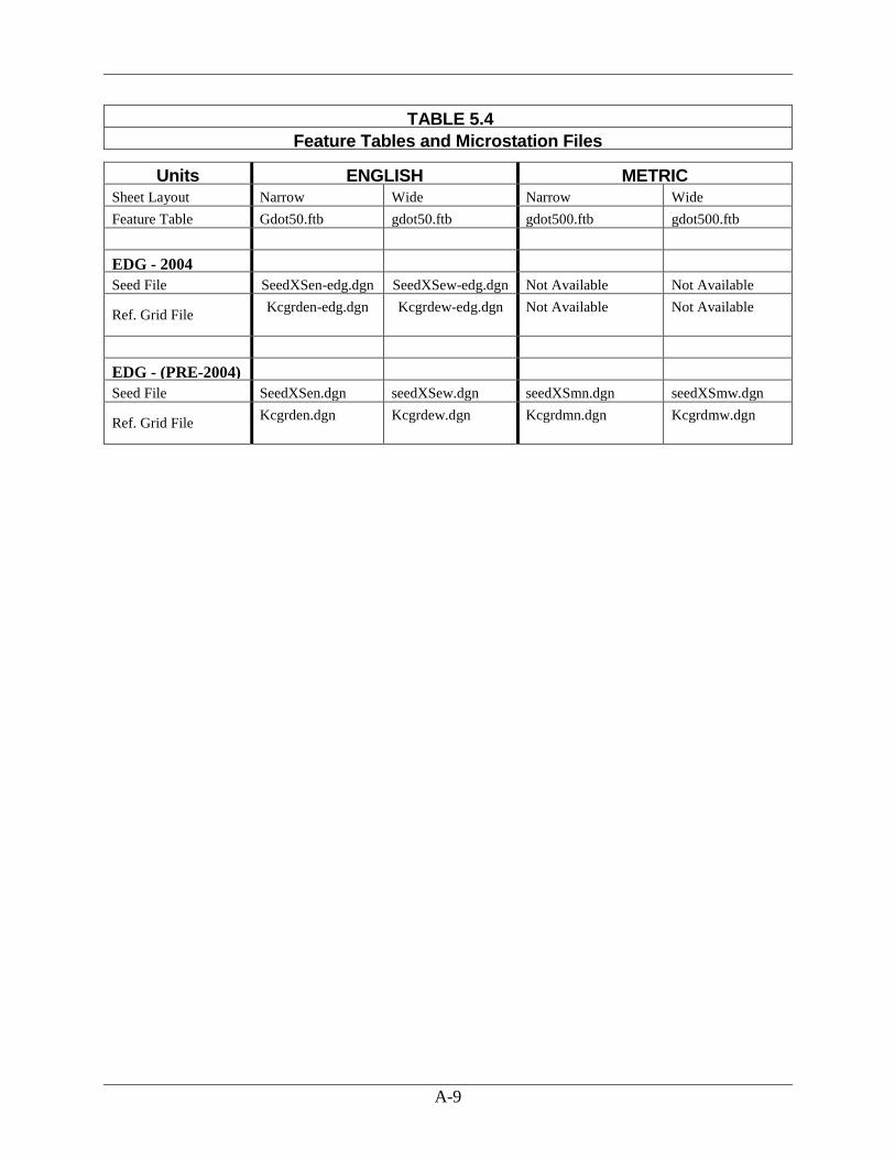
A-9
TABLE 5.4
Feature Tables and Microstation Files
Units ENGLISH METRIC Sheet Layout Narrow Wide Narrow Wide
Feature Table Gdot50.ftb gdot50.ftb gdot500.ftb gdot500.ftb
EDG - 2004
Seed File SeedXSen-edg.dgn SeedXSew-edg.dgn Not Available Not Available
Ref. Grid File Kcgrden-edg.dgn Kcgrdew-edg.dgn Not Available Not Available
EDG - (PRE-2004)
Seed File
-2004
SeedXSen.dgn seedXSew.dgn seedXSmn.dgn seedXSmw.dgn
Ref. Grid File Kcgrden.dgn Kcgrdew.dgn Kcgrdmn.dgn Kcgrdmw.dgn

0
I-1
Index
CAiCE
Original Survey ....................................... 1-1, 2-1
CEAL to CAiCE
Converting projects ......................................... 8-1
Cell Size .............................................................. 1-5
Cross-Section Sheets .......................................... 5-8
Data
2D/3D Planimetric .......................................... 2-3
3D Topographic .............................................. 2-3
Data Collector
Writing data out .............................................. 7-1
Deed Files
Generating ....................................................... 7-2
Endarea
Report File ...................................................... 7-7
Enhancement Submissions ................................. 2-7
External ............................................................ 1-10
Location of Files ............................................. 3-5
Files
Alignment File Descriptions .......................... 7-3
Alignment Report Files……………………..7-5
Providing to contractors.................................. 7-3
Initial Submission ............................................... 2-4
Internal ............................................................ 1-10
Location of Files ............................................. 3-4
GPS Grading
Report File ...................................................... 7-8
Plan Production .................................................. 5-1
Plan Sheet Elements ........................................... 5-1
Profile Sheets ...................................................... 5-6
Project Archival .................................................. 4-1
Project Data Sheet .............................................. 1-6
Location of .................................................... 1-10
Required .......................................................... 1-6
Projects
Field Surveyed ................................................ 2-3
Mapping .......................................................... 2-2
Property Enhancements .................................... 2-11
Rebuild Utility .................................................... 6-1
Standard File Names .......................................... 1-4
Standard GDOT Files ......................................... 3-1
Standard Object Names ...................................... 1-1
Survey
Original Data................................................... 2-2
Survey Data
Property .......................................................... 2-3
Use of Zones ................................................... 2-1
Text Size ............................................................. 1-5
Topo Enhancements ........................................... 2-7


![interoperability.blob.core.windows.net€¦ · Web view[MS-OXCFOLD]: Folder Object Protocol. Intellectual Property Rights Notice for Open Specifications Documentation. Technical](https://img.dokumen.tips/doc/110x75/600a5025a1e72e7f5d596aaa/web-view-ms-oxcfold-folder-object-protocol-intellectual-property-rights-notice.jpg)