Embed Size (px)
Citation preview
Geoprobe® DT22 Dual Tube Soil SamplinG SySTemConTinuouS Core Soil Sampler
STanDarD operaTinG proCeDure
Technical Bulletin No. MK3140
PREPARED: November, 2006REVISED: January, 2013
A. Assembled outer casing and inner rod string with core catcher
liner driven to collect first soil core.
B. First soil core retrieved with inner rod string and liner.
C. Sample liner, drive head, and inner rod placed inside casing.
Outer casing section, drive bumper, and drive cap added to
tool string.
D. Tool string driven to collect soil core.
E. Inner rod and liner (with second soil core) retrieved from outer
casing.
OPERATION Of ThE DUAL TUBE 22 SOIL SAMPLINg SySTEM
A. B. C.
D. E.

Standard Operating Procedure Page 2 Dual Tube 22 Soil Sampler
COPYRIGHT© 2006-2013 by Kejr, Inc.ALL RIGHTS RESERVED.
No part of this publication may be reproduced or transmitted in any form or by any means, electronic or mechanical, including photocopy, recording,
or any information storage and retrieval system, without permission inwriting from Kejr, Inc.
geoprobe® and geoprobe Systems® are Registered Trademarks of Kejr, Inc., Salina, Kansas
geoprobe® Prepacked Screens are manufactured underU.S. Patent No. 7,735,553B2.
®

Standard Operating Procedure Page 3 Dual Tube 22 Soil Sampler
1.0 OBJECTIVE
The objective of this procedure is to collect a representative soil sample at depth through an enclosed casing and recover it for visual inspection and/or chemical analysis.
2.0 BACKgROUND
2.1 Definitions
geoprobe®: A brand name of high quality, hydraulically-powered machines that utilize both static force and percussion to advance sampling and logging tools into the subsurface. The Geoprobe® brand name refers to both machines and tools manufactured by Geoprobe Systems®, Salina, Kansas. Geoprobe® tools are used to perform soil core and soil gas sampling, groundwater sampling, soil conductivity and contaminant logging, grouting, and materials injection.
* Geoprobe® and Geoprobe Systems® are registered trademarks of Kejr Engineering, Inc., Salina, Kansas
Dual Tube 22 Soil Sampling System: A direct push system for collecting continuous core samples of unconsolidated materials from within a sealed casing of Geoprobe® 2.25-inch (57 mm) outside diameter (OD) probe rods. Samples are collected and retrieved within a liner that is threaded onto the leading end of a string of Geoprobe® 1.25-inch (32 mm) OD Light-Weight Center Rods and inserted to the bottom of the outer casing. Collected samples measure up to approximately 980 ml in volume in the form of a 1.125-inch x 60-inch (29 mm x 1524 mm) core.
Liner: A 1.375-inch (35 mm) OD thin-walled, PVC tube that is inserted into the outer casing on the leading end of the inner rod string for the purpose of containing and retrieving core samples. Liners are available in two configurations; a simple open tube or a tube with a core catcher permanently attached to the leading end. Nominal liner lengths include 36 inches, 1 meter, 48 inches, and 60 inches.
**Nominal liner length identifies the length of tools with which the liner is used (see Page 8). The actual end-to-end lengths of the various DT22 liners will differ from the specified nominal lengths.
Core Catcher: A dome-shaped device positioned at the leading end of a liner to prevent loss of collected soil during retrieval of the liner and soil core. Flexible fingers at the top of the core catcher are pushed outward by soil entering the liner during advancement of the tool string. As the filled liner is subsequently retrieved, the fingers of the core catcher move back inward, effectively closing off the end of the liner and limiting soil loss. The core catcher designed for the DT22 system is made of PVC material and is permanently fused to the liner.
2.2 Discussion
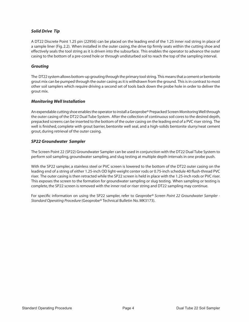
Dual tube sampling gets its name from the fact that two sets of probe rods are used to retrieve continuous soil core samples from the subsurface. One set of rods is driven into the ground as an outer casing (Fig. 2.1). These rods receive the driving force from the hammer and provide a sealed casing through which soil samples may be recovered. The second, smaller set of rods are placed inside the outer casing with a sample liner attached to the leading end of the rod string (Fig. 2.1). These smaller rods hold the liner in place as the outer casing is driven to fill the liner with soil. The inner rods are then retracted to retrieve the full liner.
Standard Geoprobe® 2.25-inch OD probe rods provide the outer casing for the DT22 Dual Tube Soil Sampling System. A cutting shoe is threaded into the leading end of the rod string. When driven into the subsurface, the cutting shoe shears a 1.125-inch OD soil core which is collected inside the casing in a clear plastic liner.
The second set of rods in the DT22 system are Geoprobe® 1.25-inch OD Light-Weight Center rods. A sample liner is attached to the end of these smaller rods and then inserted into the casing. The 1.25-inch rods hold the liner tight against the cutting shoe as the outer casing is driven to collect the soil core. Once filled with soil, the liner is removed from the bottom of the outer casing by lifting out the 1.25-inch rods.
The outer, 2.25-inch probe rods provide a cased hole through which to sample. The main advantage of sampling through a cased hole is that there is no side slough to contend with. In addition, the outer casing effectively seals the probe hole when sampling through perched water tables. These factors mean that sample cross-contamination is eliminated. The DT22 sampling system is therefore ideal for continuous coring in both saturated and unsaturated zones.
Standard Operating Procedure Page 4 Dual Tube 22 Soil Sampler
Solid Drive Tip
A DT22 Discrete Point 1.25 pin (22956) can be placed on the leading end of the 1.25 inner rod string in place of a sample liner (Fig. 2.2). When installed in the outer casing, the drive tip firmly seats within the cutting shoe and effectively seals the tool string as it is driven into the subsurface. This enables the operator to advance the outer casing to the bottom of a pre-cored hole or through undisturbed soil to reach the top of the sampling interval.
Grouting
The DT22 system allows bottom-up grouting through the primary tool string. This means that a cement or bentonite grout mix can be pumped through the outer casing as it is withdrawn from the ground. This is in contrast to most other soil samplers which require driving a second set of tools back down the probe hole in order to deliver the grout mix.
Monitoring Well Installation
An expendable cutting shoe enables the operator to install a Geoprobe® Prepacked Screen Monitoring Well through the outer casing of the DT22 Dual Tube System. After the collection of continuous soil cores to the desired depth, prepacked screens can be inserted to the bottom of the outer casing on the leading end of a PVC riser string. The well is finished, complete with grout barrier, bentonite well seal, and a high-solids bentonite slurry/neat cement grout, during retrieval of the outer casing.
SP22 Groundwater Sampler
The Screen Point 22 (SP22) Groundwater Sampler can be used in conjunction with the DT22 Dual Tube System to perform soil sampling, groundwater sampling, and slug testing at multiple depth intervals in one probe push.
With the SP22 sampler, a stainless steel or PVC screen is lowered to the bottom of the DT22 outer casing on the leading end of a string of either 1.25-inch OD light-weight center rods or 0.75-inch schedule 40 flush-thread PVC riser. The outer casing is then retracted while the SP22 screen is held in place with the 1.25-inch rods or PVC riser. This exposes the screen to the formation for groundwater sampling or slug testing. When sampling or testing is complete, the SP22 screen is removed with the inner rod or riser string and DT22 sampling may continue.
For specific information on using the SP22 sampler, refer to Geoprobe® Screen Point 22 Groundwater Sampler - Standard Operating Procedure (Geoprobe® Technical Bulletin No. MK3173).
Standard Operating Procedure Page 5 Dual Tube 22 Soil Sampler
FIGURE 2.1Outer Casing Driven With Liner
FIGURE 2.2Outer Casing Driven With Solid Drive Tip
Soil Collectedin Liner
Outer Casing(2.25-in. ODprobe rods)
Inner Rod String(1.25-in. ODLight-Weight Center Rod)
Solid Drive Tip
Outer Casing(2.25-in. ODprobe rods)
Inner Rod String(1.25-in. ODLight-Weight Center Rod)
Inner rod string raised to retrieve Solid Drive Tip
Inner rod string raised to retrieve filled liner
Standard Operating Procedure Page 6 Dual Tube 22 Soil Sampler
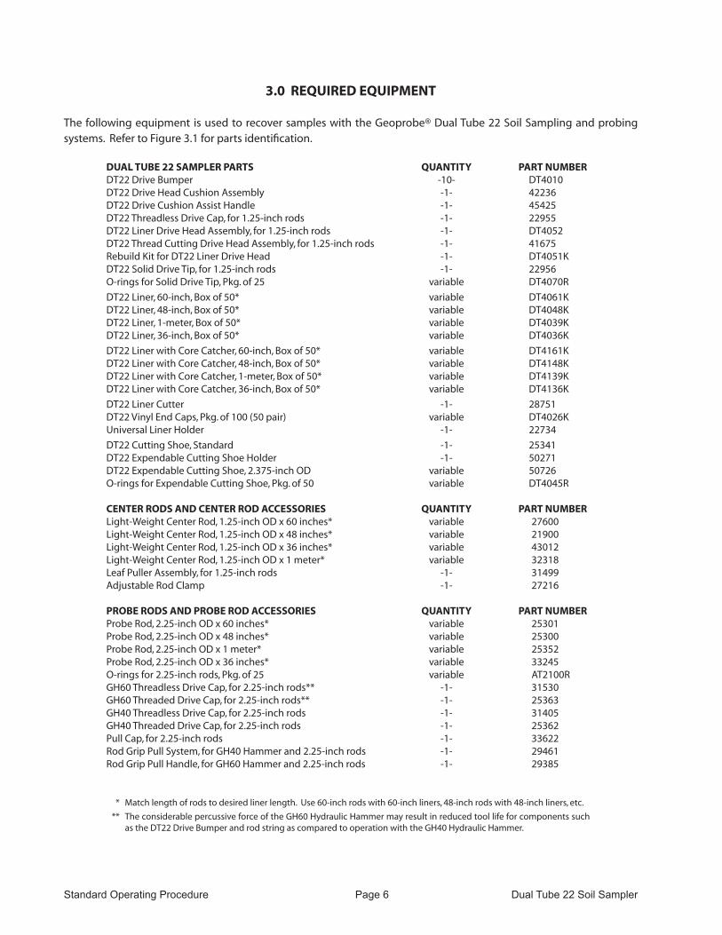
3.0 REQUIRED EQUIPMENT
The following equipment is used to recover samples with the Geoprobe® Dual Tube 22 Soil Sampling and probing systems. Refer to Figure 3.1 for parts identification.
DUAL TUBE 22 SAMPLER PARTS QUANTITy PART NUMBERDT22 Drive Bumper -10- DT4010DT22 Drive Head Cushion Assembly -1- 42236DT22 Drive Cushion Assist Handle -1- 45425DT22 Threadless Drive Cap, for 1.25-inch rods -1- 22955DT22 Liner Drive Head Assembly, for 1.25-inch rods -1- DT4052DT22 Thread Cutting Drive Head Assembly, for 1.25-inch rods -1- 41675Rebuild Kit for DT22 Liner Drive Head -1- DT4051KDT22 Solid Drive Tip, for 1.25-inch rods -1- 22956O-rings for Solid Drive Tip, Pkg. of 25 variable DT4070R
DT22 Liner, 60-inch, Box of 50* variable DT4061KDT22 Liner, 48-inch, Box of 50* variable DT4048KDT22 Liner, 1-meter, Box of 50* variable DT4039KDT22 Liner, 36-inch, Box of 50* variable DT4036K
DT22 Liner with Core Catcher, 60-inch, Box of 50* variable DT4161KDT22 Liner with Core Catcher, 48-inch, Box of 50* variable DT4148KDT22 Liner with Core Catcher, 1-meter, Box of 50* variable DT4139KDT22 Liner with Core Catcher, 36-inch, Box of 50* variable DT4136K
DT22 Liner Cutter -1- 28751DT22 Vinyl End Caps, Pkg. of 100 (50 pair) variable DT4026KUniversal Liner Holder -1- 22734
DT22 Cutting Shoe, Standard -1- 25341DT22 Expendable Cutting Shoe Holder -1- 50271DT22 Expendable Cutting Shoe, 2.375-inch OD variable 50726O-rings for Expendable Cutting Shoe, Pkg. of 50 variable DT4045R
CENTER RODS AND CENTER ROD ACCESSORIES QUANTITy PART NUMBERLight-Weight Center Rod, 1.25-inch OD x 60 inches* variable 27600Light-Weight Center Rod, 1.25-inch OD x 48 inches* variable 21900Light-Weight Center Rod, 1.25-inch OD x 36 inches* variable 43012Light-Weight Center Rod, 1.25-inch OD x 1 meter* variable 32318Leaf Puller Assembly, for 1.25-inch rods -1- 31499Adjustable Rod Clamp -1- 27216
PROBE RODS AND PROBE ROD ACCESSORIES QUANTITy PART NUMBERProbe Rod, 2.25-inch OD x 60 inches* variable 25301Probe Rod, 2.25-inch OD x 48 inches* variable 25300Probe Rod, 2.25-inch OD x 1 meter* variable 25352Probe Rod, 2.25-inch OD x 36 inches* variable 33245O-rings for 2.25-inch rods, Pkg. of 25 variable AT2100RGH60 Threadless Drive Cap, for 2.25-inch rods** -1- 31530GH60 Threaded Drive Cap, for 2.25-inch rods** -1- 25363GH40 Threadless Drive Cap, for 2.25-inch rods -1- 31405GH40 Threaded Drive Cap, for 2.25-inch rods -1- 25362Pull Cap, for 2.25-inch rods -1- 33622Rod Grip Pull System, for GH40 Hammer and 2.25-inch rods -1- 29461Rod Grip Pull Handle, for GH60 Hammer and 2.25-inch rods -1- 29385
* Match length of rods to desired liner length. Use 60-inch rods with 60-inch liners, 48-inch rods with 48-inch liners, etc.
** The considerable percussive force of the GH60 Hydraulic Hammer may result in reduced tool life for components such as the DT22 Drive Bumper and rod string as compared to operation with the GH40 Hydraulic Hammer.
Standard Operating Procedure Page 7 Dual Tube 22 Soil Sampler
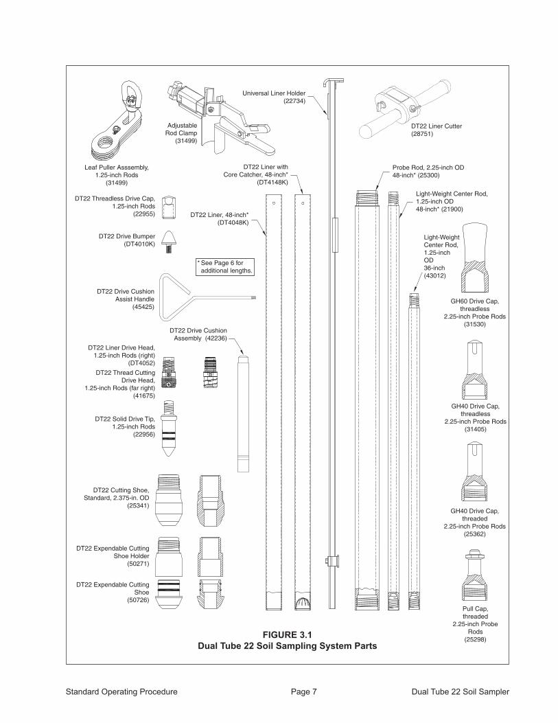
FIGURE 3.1Dual Tube 22 Soil Sampling System Parts
DT22 Liner, 48-inch* (DT4048K)
Pull Cap, threaded
2.25-inch Probe Rods
(25298)
GH40 Drive Cap, threadless
2.25-inch Probe Rods(31405)
DT22 Expendable Cutting Shoe Holder
(50271)
Light-Weight Center Rod, 1.25-inch OD48-inch* (21900)
Probe Rod, 2.25-inch OD48-inch* (25300)
GH60 Drive Cap, threadless
2.25-inch Probe Rods(31530)
DT22 Expendable Cutting Shoe
(50726)
DT22 Cutting Shoe, Standard, 2.375-in. OD
(25341)
DT22 Solid Drive Tip,1.25-inch Rods
(22956)
DT22 Liner Drive Head, 1.25-inch Rods (right)
(DT4052)
DT22 Thread Cutting Drive Head,
1.25-inch Rods (far right)(41675)
DT22 Drive Bumper(DT4010K)
DT22 Threadless Drive Cap, 1.25-inch Rods
(22955)
DT22 Liner with Core Catcher, 48-inch*
(DT4148K)
GH40 Drive Cap, threaded
2.25-inch Probe Rods(25362)
DT22 Liner Cutter (28751)
Universal Liner Holder(22734)
Leaf Puller Asssembly, 1.25-inch Rods
(31499)
Adjustable Rod Clamp
(31499)
* See Page 6 for additional lengths.
Light-Weight Center Rod, 1.25-inch OD36-inch(43012)
DT22 Drive Cushion Assembly (42236)
DT22 Drive Cushion Assist Handle
(45425)

Standard Operating Procedure Page 8 Dual Tube 22 Soil Sampler
3.1 Tool Options
Three major components of the DT22 Soil Sampling System are probe rods, sample liners, and cutting shoes. These items are manufactured in a variety of sizes to fit the specific needs of the operator. This section identifies the specific tool options available for use with the DT22 Dual Tube System.
Probe Rods
Geoprobe® 1.25-inch (32 mm) OD Light-Weight Center Rods and 2.25-inch (57 mm) OD probe rods are required to operate the DT22 Soil Sampling System. Both rod sets (1.25-inch and 2.25-inch) must be of the same length.
Sample Liners
Sample liners are made of a heavy-duty clear plastic for convenient inspection of the soil sample. Lengths of 36, 48, 60 inches, and 1 meter are available with an OD of 1.375 inches (35 mm).
Sample liners with integral core catchers are available in lengths of 36, 48, 60 inches, and 1 meter. Utilize the core catcher liners when sampling flowing sands, noncohesive soils, extremely dry soils, or any other materials that fall from the liner during retrieval. DT22 core catcher liners are used with the same equipment as open sample liners. No special tooling or adapters are required.
Cutting Shoes
The standard DT22 Cutting Shoe is available for use with the DT22 Dual Tube System (Fig. 3.2). The DT22 sampling system may also employ an expendable cutting shoe. In this arrangement, a DT22 Expendable Cutting Shoe Holder (50271) is threaded into the leading end of the outer casing. A DT22 Expendable Cutting Shoe (50726) is then inserted into the holder. Upon completion of soil sampling, the outer casing is withdrawn slightly. The expendable cutting shoe detaches from the holder, leaving an open casing through which a prepacked screen monitoring well may be installed. Dimensions for the expendable cutting shoe are the same as the standard cutting shoe (ID = 1.125 in. (29 mm) and OD = 2.375 in. (60 mm)).
FIGURE 3.2Cutting Shoe Options for the DT22 Dual Tube Soil Sampling System
2.375 in.(60 mm)
1.125 in.(29 mm)
1.5 in.(38 mm)
DT22 Expendable Cutting Shoe Holder (50271)
DT22 Expendable Cutting Shoe(50726)
1.125 in.(29 mm)
2.5 in.(63.5 mm)
DT22 Cutting Shoe, Standard (25341)

Standard Operating Procedure Page 9 Dual Tube 22 Soil Sampler
4.0 OPERATION
4.1 Decontamination
Before and after each use, thoroughly clean all parts of the sampling system according to project requirements. Parts should also be inspected for wear or damage. During sampling, a clean new liner is used for each soil core.
4.2 Operational Overview
The DT22 Soil Sampling System is designed to collect continuous soil cores. Sampling may begin either from ground surface or a predetermined depth below ground. Once sampling begins, consecutive soil cores must be removed as the outer casing is advanced to greater depths.
When sampling is to begin at the ground surface, the first soil core should be collected using a core catcher liner to maximize sample recovery (Fig. 4.1-A). This is especially true when the first core is composed of dry, loose soil. Upon removal of the first liner and soil core (Fig. 4.1-B), a new liner is inserted to the bottom of the outer casing on the end of an inner rod. A section of outer casing is added to the tool string (Fig. 4.1-C) and the entire tool string is driven to fill the liner with soil (Fig. 4.1-D). The filled liner is removed from the outer casing to retrieve the second soil core (Fig. 4.1-E). A new liner is then inserted to the bottom of the outer casing and the process is repeated over the entire sampling interval.
FIGURE 4.1Continuous Core Sampling From Ground Surface with Dual Tube 22 System
A. B. C.
D. E.

Standard Operating Procedure Page 10 Dual Tube 22 Soil Sampler
When the sampling interval begins at some depth below ground surface, a DT22 Solid Drive Tip is installed in the outer casing and the entire assembly is driven from ground surface directly through undisturbed soil (Fig. 4.2-A). This enables the operator to reach the top of the sampling interval without stopping to remove unwanted soil cores. Once the interval is reached, the solid drive tip is removed (Fig 4.2-B) and sampling continues as described in the preceding paragraphs (Fig. 4.2-C, Fig. 4.2-D, and Fig. 4.2-E).
Specific instructions for the assembly and operation of the DT22 Dual Tube Soil Sampling System are given in the following sections.
FIGURE 4.2Outer Casing Driven Through Undisturbed Soil to Begin Sampling with DT22 System
A. B. C.
D. E.
Standard Operating Procedure Page 11 Dual Tube 22 Soil Sampler
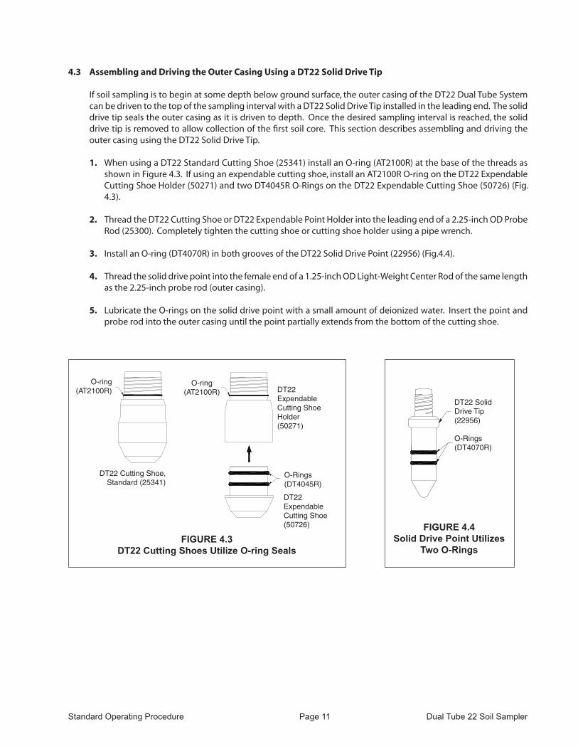
4.3 Assembling and Driving the Outer Casing Using a DT22 Solid Drive Tip
If soil sampling is to begin at some depth below ground surface, the outer casing of the DT22 Dual Tube System can be driven to the top of the sampling interval with a DT22 Solid Drive Tip installed in the leading end. The solid drive tip seals the outer casing as it is driven to depth. Once the desired sampling interval is reached, the solid drive tip is removed to allow collection of the first soil core. This section describes assembling and driving the outer casing using the DT22 Solid Drive Tip.
1. When using a DT22 Standard Cutting Shoe (25341) install an O-ring (AT2100R) at the base of the threads as shown in Figure 4.3. If using an expendable cutting shoe, install an AT2100R O-ring on the DT22 Expendable Cutting Shoe Holder (50271) and two DT4045R O-Rings on the DT22 Expendable Cutting Shoe (50726) (Fig. 4.3).
2. Thread the DT22 Cutting Shoe or DT22 Expendable Point Holder into the leading end of a 2.25-inch OD Probe Rod (25300). Completely tighten the cutting shoe or cutting shoe holder using a pipe wrench.
3. Install an O-ring (DT4070R) in both grooves of the DT22 Solid Drive Point (22956) (Fig.4.4).
4. Thread the solid drive point into the female end of a 1.25-inch OD Light-Weight Center Rod of the same length as the 2.25-inch probe rod (outer casing).
5. Lubricate the O-rings on the solid drive point with a small amount of deionized water. Insert the point and probe rod into the outer casing until the point partially extends from the bottom of the cutting shoe.
FIGURE 4.3DT22 Cutting Shoes Utilize O-ring Seals
FIGURE 4.4Solid Drive Point Utilizes
Two O-Rings
DT22 Expendable Cutting ShoeHolder (50271)
DT22 Cutting Shoe, Standard (25341)
O-Rings(DT4045R)
O-ring(AT2100R)
O-ring(AT2100R)
DT22 Solid Drive Tip (22956)
O-Rings(DT4070R)
DT22 Expendable Cutting Shoe (50726)

Standard Operating Procedure Page 12 Dual Tube 22 Soil Sampler
FIGURE 4.5Outer Casing with Solid Drive Tip
GH40 Threadless Drive Cap (31405)
or GH60 Threadless Drive Cap (31530)
DT22 Threadless Drive Cap (22955)
Inner Rod (1.25-inch OD
Light-Weight Center Rod)
Outer Casing(2.25-inch OD
Probe Rod)
DT22 Solid Drive Trip
(22956)
DT22 Cutting Shoe (shown) or
Expendable Cutting Shoe and
Expendable Cutting Shoe Holder
6. Place a DT22 Threadless Drive Cap (22955) on top of the inner rod (Fig. 4.5). This drive cap is threadless for quick installation/removal, yet still provides protection for the probe rod threads.
7. Install a GH40 Threadless Drive Cap (31405) or GH60 Threadless Drive Cap (31530) on the 2.25-inch probe rod (outer casing) as shown in Figure 4.5.
Certain soil conditions may allow the outer casing to advance slightly ahead of the inner rod string when using a threadless drive cap on the outer casing. The result is poor sample recovery and alignment problems when adding rods to the tool string. Utilizing a threaded drive cap on the 2.25-inch probe rods may solve this issue. The GH40 Series (25362) and GH60 Series (25363) threaded drive caps secure the inner rod string of the DT22 system during percussion so that the outer casing and inner rod string are advanced as one assembly.
NOTE: Do not allow the threaded drive cap to unthread while driving the tool string. failure to keep the drive cap tight during percussion will fuse the drive cap to the outer casing and permanently damage the threads of both the drive cap and top probe rod.
8. Place the assembled outer casing section under the direct push machine for driving. Position the casing directly under the hammer with the cutting shoe centered between the toes of the probe foot.
9. Lower the hydraulic hammer onto the drive cap and advance the outer casing into the subsurface.
10. Raise the hydraulic hammer and remove the drive cap from the outer casing and the threadless drive cap from the inner rod string.
11. Place an O-ring (AT2100R) on the outer casing section that
extends from the ground (Fig. 4.6).
12. Thread a 1.25-inch Light-Weight Center Rod onto the inner rod string. Place a 2.25-inch probe rod over the inner rods and thread it onto the outer casing (Fig. 4.7). Completely tighten the outer casing using a pipe wrench.
13. Place the threadless drive cap on top of the inner rod. Thread the 2.25-inch drive cap over the threadless drive cap and onto the outer casing.
14. Lower the hydraulic hammer onto the drive cap and advance the outer casing into the subsurface.
Repeat Steps 10-13 until the leading end of the outer casing is at the top of the proposed sampling interval. Continue with Step 15 to remove the DT22 Solid Drive Point for sampling.
15. Raise the hydraulic hammer and retract the probe derrick to provide access to the top of the tool string.
Standard Operating Procedure Page 13 Dual Tube 22 Soil Sampler
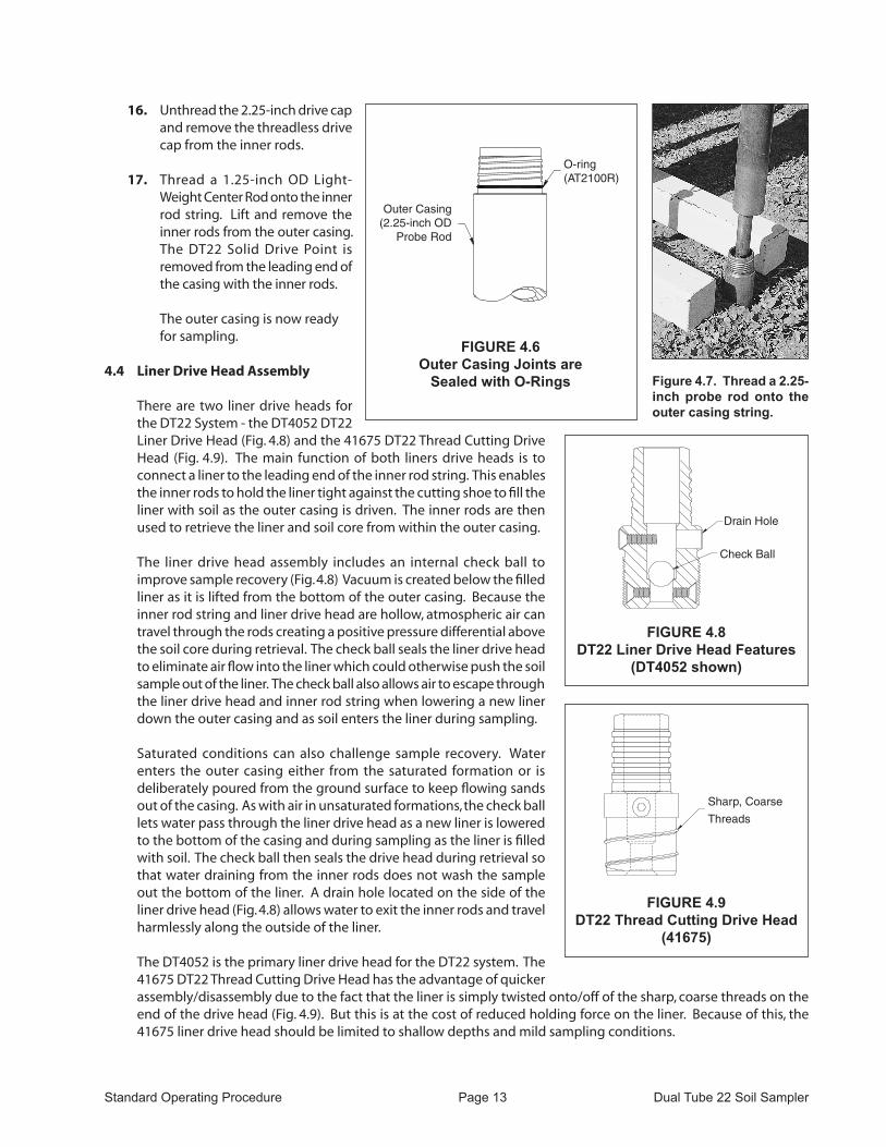
16. Unthread the 2.25-inch drive cap and remove the threadless drive cap from the inner rods.
17. Thread a 1.25-inch OD Light-Weight Center Rod onto the inner rod string. Lift and remove the inner rods from the outer casing. The DT22 Solid Drive Point is removed from the leading end of the casing with the inner rods.
The outer casing is now ready for sampling.
4.4 Liner Drive head Assembly
There are two liner drive heads for the DT22 System - the DT4052 DT22 Liner Drive Head (Fig. 4.8) and the 41675 DT22 Thread Cutting Drive Head (Fig. 4.9). The main function of both liners drive heads is to connect a liner to the leading end of the inner rod string. This enables the inner rods to hold the liner tight against the cutting shoe to fill the liner with soil as the outer casing is driven. The inner rods are then used to retrieve the liner and soil core from within the outer casing.
The liner drive head assembly includes an internal check ball to improve sample recovery (Fig. 4.8) Vacuum is created below the filled liner as it is lifted from the bottom of the outer casing. Because the inner rod string and liner drive head are hollow, atmospheric air can travel through the rods creating a positive pressure differential above the soil core during retrieval. The check ball seals the liner drive head to eliminate air flow into the liner which could otherwise push the soil sample out of the liner. The check ball also allows air to escape through the liner drive head and inner rod string when lowering a new liner down the outer casing and as soil enters the liner during sampling.
Saturated conditions can also challenge sample recovery. Water enters the outer casing either from the saturated formation or is deliberately poured from the ground surface to keep flowing sands out of the casing. As with air in unsaturated formations, the check ball lets water pass through the liner drive head as a new liner is lowered to the bottom of the casing and during sampling as the liner is filled with soil. The check ball then seals the drive head during retrieval so that water draining from the inner rods does not wash the sample out the bottom of the liner. A drain hole located on the side of the liner drive head (Fig. 4.8) allows water to exit the inner rods and travel harmlessly along the outside of the liner.
The DT4052 is the primary liner drive head for the DT22 system. The 41675 DT22 Thread Cutting Drive Head has the advantage of quicker assembly/disassembly due to the fact that the liner is simply twisted onto/off of the sharp, coarse threads on the end of the drive head (Fig. 4.9). But this is at the cost of reduced holding force on the liner. Because of this, the 41675 liner drive head should be limited to shallow depths and mild sampling conditions.
FIGURE 4.6Outer Casing Joints are
Sealed with O-Rings
Outer Casing (2.25-inch OD
Probe Rod
O-ring(AT2100R)
Figure 4.7. Thread a 2.25-inch probe rod onto the outer casing string.
FIGURE 4.8DT22 Liner Drive Head Features
(DT4052 shown)
Drain Hole
Check Ball
FIGURE 4.9DT22 Thread Cutting Drive Head
(41675)
Sharp, Coarse
Threads
Standard Operating Procedure Page 14 Dual Tube 22 Soil Sampler
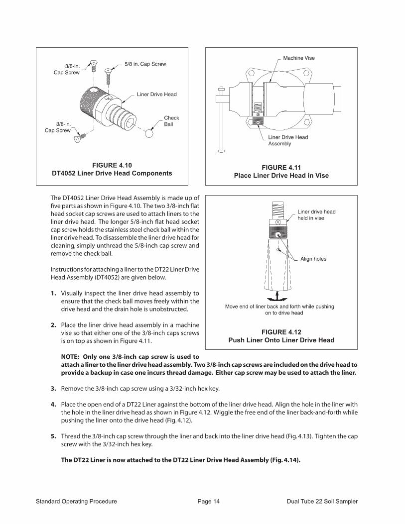
The DT4052 Liner Drive Head Assembly is made up of five parts as shown in Figure 4.10. The two 3/8-inch flat head socket cap screws are used to attach liners to the liner drive head. The longer 5/8-inch flat head socket cap screw holds the stainless steel check ball within the liner drive head. To disassemble the liner drive head for cleaning, simply unthread the 5/8-inch cap screw and remove the check ball.
Instructions for attaching a liner to the DT22 Liner Drive Head Assembly (DT4052) are given below.
1. Visually inspect the liner drive head assembly to ensure that the check ball moves freely within the drive head and the drain hole is unobstructed.
2. Place the liner drive head assembly in a machine vise so that either one of the 3/8-inch caps screws is on top as shown in Figure 4.11.
NOTE: Only one 3/8-inch cap screw is used to attach a liner to the liner drive head assembly. Two 3/8-inch cap screws are included on the drive head to provide a backup in case one incurs thread damage. Either cap screw may be used to attach the liner.
3. Remove the 3/8-inch cap screw using a 3/32-inch hex key.
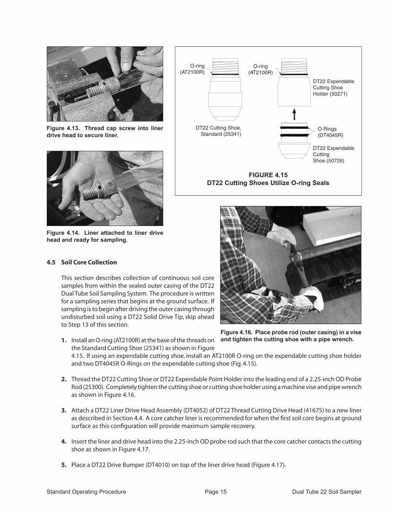
4. Place the open end of a DT22 Liner against the bottom of the liner drive head. Align the hole in the liner with the hole in the liner drive head as shown in Figure 4.12. Wiggle the free end of the liner back-and-forth while pushing the liner onto the drive head (Fig. 4.12).
5. Thread the 3/8-inch cap screw through the liner and back into the liner drive head (Fig. 4.13). Tighten the cap screw with the 3/32-inch hex key.
The DT22 Liner is now attached to the DT22 Liner Drive head Assembly (fig. 4.14).
FIGURE 4.11Place Liner Drive Head in Vise
Machine Vise
Liner Drive HeadAssembly
FIGURE 4.10DT4052 Liner Drive Head Components
3/8-in.Cap Screw
5/8 in. Cap Screw
3/8-in.Cap Screw
Liner Drive Head
CheckBall
FIGURE 4.12Push Liner Onto Liner Drive Head
Liner drive headheld in vise
Align holes
Move end of liner back and forth while pushing on to drive head
Standard Operating Procedure Page 15 Dual Tube 22 Soil Sampler
4.5 Soil Core Collection
This section describes collection of continuous soil core samples from within the sealed outer casing of the DT22 Dual Tube Soil Sampling System. The procedure is written for a sampling series that begins at the ground surface. If sampling is to begin after driving the outer casing through undisturbed soil using a DT22 Solid Drive Tip, skip ahead to Step 13 of this section.
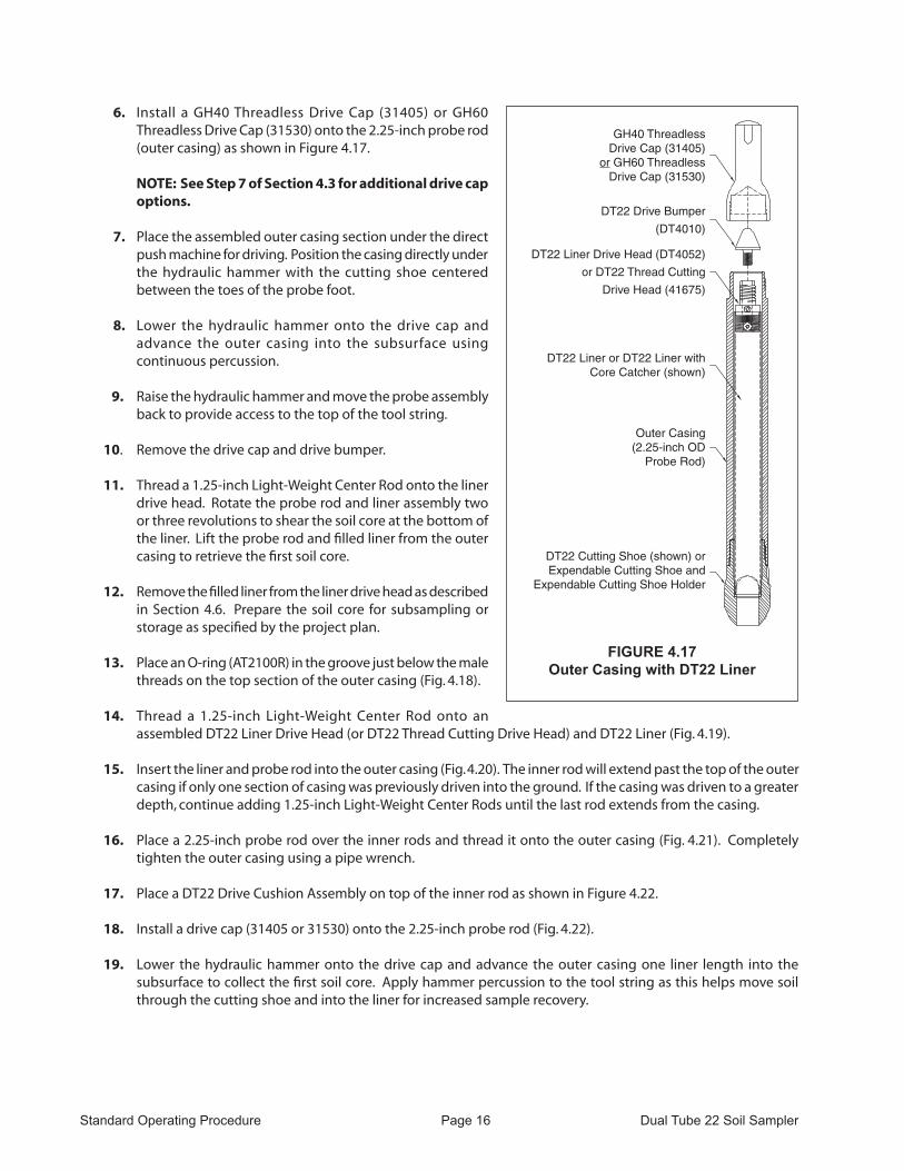
1. Install an O-ring (AT2100R) at the base of the threads on the Standard Cutting Shoe (25341) as shown in Figure 4.15. If using an expendable cutting shoe, install an AT2100R O-ring on the expendable cutting shoe holder and two DT4045R O-Rings on the expendable cutting shoe (Fig. 4.15).
2. Thread the DT22 Cutting Shoe or DT22 Expendable Point Holder into the leading end of a 2.25-inch OD Probe
Rod (25300). Completely tighten the cutting shoe or cutting shoe holder using a machine vise and pipe wrench as shown in Figure 4.16.
3. Attach a DT22 Liner Drive Head Assembly (DT4052) of DT22 Thread Cutting Drive Head (41675) to a new liner as described in Section 4.4. A core catcher liner is recommended for when the first soil core begins at ground surface as this configuration will provide maximum sample recovery.
4. Insert the liner and drive head into the 2.25-inch OD probe rod such that the core catcher contacts the cutting shoe as shown in Figure 4.17.
5. Place a DT22 Drive Bumper (DT4010) on top of the liner drive head (Figure 4.17).
Figure 4.13. Thread cap screw into liner drive head to secure liner.
Figure 4.14. Liner attached to liner drive head and ready for sampling.
FIGURE 4.15DT22 Cutting Shoes Utilize O-ring Seals
DT22 Expendable Cutting Shoe Holder (50271)
DT22 Cutting Shoe, Standard (25341)
O-Rings(DT4045R)
O-ring(AT2100R)
DT22 Expendable Cutting Shoe (50726)
O-ring(AT2100R)
Figure 4.16. Place probe rod (outer casing) in a vise and tighten the cutting shoe with a pipe wrench.
Standard Operating Procedure Page 16 Dual Tube 22 Soil Sampler
6. Install a GH40 Threadless Drive Cap (31405) or GH60 Threadless Drive Cap (31530) onto the 2.25-inch probe rod (outer casing) as shown in Figure 4.17.
NOTE: See Step 7 of Section 4.3 for additional drive cap options.
7. Place the assembled outer casing section under the direct push machine for driving. Position the casing directly under the hydraulic hammer with the cutting shoe centered between the toes of the probe foot.
8. Lower the hydraulic hammer onto the drive cap and advance the outer casing into the subsurface using continuous percussion.
9. Raise the hydraulic hammer and move the probe assembly back to provide access to the top of the tool string.
10. Remove the drive cap and drive bumper.
11. Thread a 1.25-inch Light-Weight Center Rod onto the liner drive head. Rotate the probe rod and liner assembly two or three revolutions to shear the soil core at the bottom of the liner. Lift the probe rod and filled liner from the outer casing to retrieve the first soil core.
12. Remove the filled liner from the liner drive head as described in Section 4.6. Prepare the soil core for subsampling or storage as specified by the project plan.
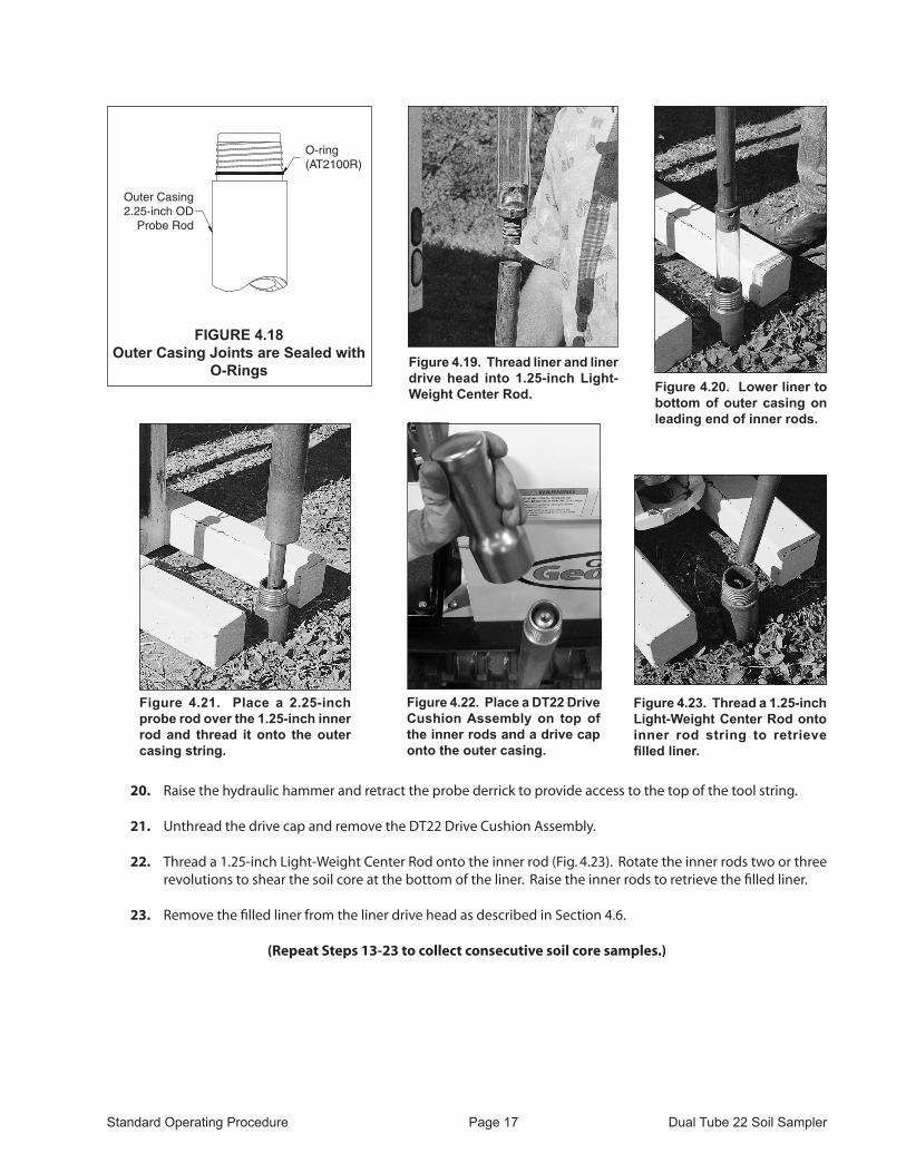
13. Place an O-ring (AT2100R) in the groove just below the male threads on the top section of the outer casing (Fig. 4.18).
14. Thread a 1.25-inch Light-Weight Center Rod onto an assembled DT22 Liner Drive Head (or DT22 Thread Cutting Drive Head) and DT22 Liner (Fig. 4.19).
15. Insert the liner and probe rod into the outer casing (Fig. 4.20). The inner rod will extend past the top of the outer casing if only one section of casing was previously driven into the ground. If the casing was driven to a greater depth, continue adding 1.25-inch Light-Weight Center Rods until the last rod extends from the casing.
16. Place a 2.25-inch probe rod over the inner rods and thread it onto the outer casing (Fig. 4.21). Completely tighten the outer casing using a pipe wrench.
17. Place a DT22 Drive Cushion Assembly on top of the inner rod as shown in Figure 4.22.
18. Install a drive cap (31405 or 31530) onto the 2.25-inch probe rod (Fig. 4.22).
19. Lower the hydraulic hammer onto the drive cap and advance the outer casing one liner length into the subsurface to collect the first soil core. Apply hammer percussion to the tool string as this helps move soil through the cutting shoe and into the liner for increased sample recovery.
FIGURE 4.17Outer Casing with DT22 Liner
GH40 Threadless Drive Cap (31405)
or GH60 Threadless Drive Cap (31530)
DT22 Drive Bumper
(DT4010)
DT22 Liner Drive Head (DT4052)
or DT22 Thread Cutting
Drive Head (41675)
Outer Casing(2.25-inch OD
Probe Rod)
DT22 Cutting Shoe (shown) orExpendable Cutting Shoe and
Expendable Cutting Shoe Holder
DT22 Liner or DT22 Liner with Core Catcher (shown)
Standard Operating Procedure Page 17 Dual Tube 22 Soil Sampler
20. Raise the hydraulic hammer and retract the probe derrick to provide access to the top of the tool string.
21. Unthread the drive cap and remove the DT22 Drive Cushion Assembly.
22. Thread a 1.25-inch Light-Weight Center Rod onto the inner rod (Fig. 4.23). Rotate the inner rods two or three revolutions to shear the soil core at the bottom of the liner. Raise the inner rods to retrieve the filled liner.
23. Remove the filled liner from the liner drive head as described in Section 4.6.
(Repeat Steps 13-23 to collect consecutive soil core samples.)
FIGURE 4.18Outer Casing Joints are Sealed with
O-Rings
Outer Casing 2.25-inch OD
Probe Rod
O-ring(AT2100R)
Figure 4.19. Thread liner and liner drive head into 1.25-inch Light-Weight Center Rod. Figure 4.20. Lower liner to
bottom of outer casing on leading end of inner rods.
Figure 4.21. Place a 2.25-inch probe rod over the 1.25-inch inner rod and thread it onto the outer casing string.
Figure 4.22. Place a DT22 Drive Cushion Assembly on top of the inner rods and a drive cap onto the outer casing.
Figure 4.23. Thread a 1.25-inch Light-Weight Center Rod onto inner rod string to retrieve filled liner.

Standard Operating Procedure Page 18 Dual Tube 22 Soil Sampler
4.6 Removing the DT22 Liner Drive head (DT4052) from a filled DT22 Liner
The liner drive head remains attached to the filled liner after retrieval from the outer casing (Fig. 4.24). In order to decontaminate the drive head for further sampling, it must first be removed from the filled liner. The DT22 Thread Cutting Drive Head (41675) is removed by simply placing the drive head in a vise and manually unthreading the liner. The process is slightly more involved for the DT22 Liner Drive Head (DT4052), but is easily accomplished using a machine vise and sharp utility knife as described below.
Place the liner drive head in the machine vise such that the 3/8-inch cap screw threaded through the liner is positioned on top. Remove the cap screw with a 3/32-inch hex key.
Using a utility knife, score a line from the top of the liner to the bottom of the drive head (Fig. 4.25). Move the free end of the liner side-to-side until the top of the liner splits and releases from the drive head (Fig. 4.26). The soil core may now be prepared for storage or analysis according to project guidelines.
Cutting the Liner Open
The DT22 Liner Cutter (28751) is a light-weight cutter that safely and efficiently slices an approximately 1.125-inch wide strip the entire length of a filled polymer liner. Two hooked cutting blades, one mounted on each side of the cutter as show in Figure 4.27, make a lengthwise opening in the liner for easy access and viewing of the sample material. The cutter features guards (covers) for each blade to maximize operator safety. However, care should always be used when operating this device.
Figure 4.24. Liner drive head remains attached to filled liner after retrieval from outer casing.
Figure 4.25. Score a line from top of liner to base of liner drive head using a utility knife.
Figure 4.26. Move free end of liner back-and-forth to split liner and free it from the liner drive head.
Figure 4.27. The DT22 Liner Cutter (28751) safely removes an approximately 1.125-inch wide strip the entire length of a filled polymer liner.
Standard Operating Procedure Page 19 Dual Tube 22 Soil Sampler
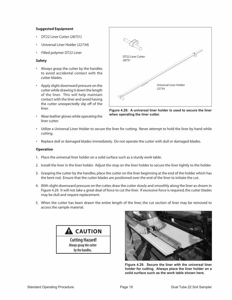
Suggested Equipment
• DT22 Liner Cutter (28751)
• Universal Liner Holder (22734)
• Filled polymer DT22 Liner
Safety
• Always grasp the cutter by the handles to avoid accidental contact with the cutter blades.
• Apply slight downward pressure on the cutter while drawing it down the length of the liner. This will help maintain contact with the liner and avoid having the cutter unexpectedly slip off of the liner.
• Wear leather gloves while operating the liner cutter.
• Utilize a Universal Liner Holder to secure the liner for cutting. Never attempt to hold the liner by hand while cutting.
• Replace dull or damaged blades immediately. Do not operate the cutter with dull or damaged blades.
Operation
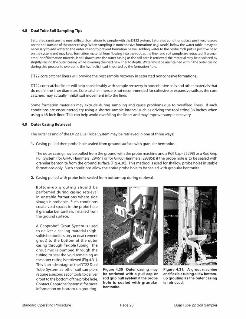
1. Place the universal liner holder on a solid surface such as a sturdy work table.
2. Install the liner in the liner holder. Adjust the stop on the liner holder to secure the liner tightly to the holder.
3. Grasping the cutter by the handles, place the cutter on the liner beginning at the end of the holder which has the bent rod. Ensure that the cutter blades are positioned over the end of the liner to initiate the cut.
4. With slight downward pressure on the cutter, draw the cutter slowly and smoothly along the liner as shown in Figure 4.29. It will not take a great deal of force to cut the liner. If excessive force is required, the cutter blades may be dull and require replacement.
5. When the cutter has been drawn the entire length of the liner, the cut section of liner may be removed to access the sample material.
DT22 Liner Cutter28751
Universal Liner Holder22734
Figure 4.28: A universal liner holder is used to secure the liner when operating the liner cutter.
Figure 4.29. Secure the liner with the universal liner holder for cutting. Always place the liner holder on a solid surface such as the work table shown here.
CAUTIONCutting Hazard!
Always grasp the cutterby the handles.
Standard Operating Procedure Page 20 Dual Tube 22 Soil Sampler
4.8 Dual Tube Soil Sampling Tips
Saturated sands are the most difficult formations to sample with the DT22 system. Saturated conditions place positive pressure on the soil outside of the outer casing. When sampling in noncohesive formations (e.g. sands) below the water table, it may be necessary to add water to the outer casing to prevent formation heave. Adding water to the probe rods puts a positive head on the system and may keep formation material from flowing into the rods as the liner and soil sample are retracted. If a small amount of formation material is still drawn into the outer casing as the soil core is retrieved, the material may be displaced by slightly raising the outer casing while lowering the next new liner to depth. Water must be maintained within the outer casing during this process to overcome the hydraulic head imparted by the formation fluid.
DT22 core catcher liners will provide the best sample recovery in saturated noncohesive formations.
DT22 core catcher liners will help considerably with sample recovery in noncohesive soils and other materials that do not fill the liner diameter. Core catcher liners are not recommended for cohesive or expansive soils as the core catchers may actually inhibit soil movement into the liner.
Some formation materials may extrude during sampling and cause problems due to overfilled liners. If such conditions are encountered, try using a shorter sample interval such as driving the tool string 36 inches when using a 48-inch liner. This can help avoid overfilling the liners and may improve sample recovery.
4.9 Outer Casing Retrieval
The outer casing of the DT22 Dual Tube System may be retrieved in one of three ways:
1. Casing pulled then probe hole sealed from ground surface with granular bentonite.
The outer casing may be pulled from the ground with the probe machine and a Pull Cap (25298) or a Rod Grip Pull System (for GH40 Hammers [29461] or for GH60 Hammers [29385]) if the probe hole is to be sealed with granular bentonite from the ground surface (Fig. 4.30). This method is used for shallow probe holes in stable formations only. Such conditions allow the entire probe hole to be sealed with granular bentonite.
2. Casing pulled with probe hole sealed from bottom-up during retrieval.
Bottom-up grouting should be performed during casing retrieval in unstable formations where side slough is probable. Such conditions create void spaces in the probe hole if granular bentonite is installed from the ground surface.
A Geoprobe® Grout System is used to deliver a sealing material (high-solids bentonite slurry or neat cement grout) to the bottom of the outer casing through flexible tubing. The grout mix is pumped through the tubing to seal the void remaining as the outer casing is retrieved (Fig. 4.31). This is an advantage of the DT22 Dual Tube System as other soil samplers require a second set of tools to deliver grout to the bottom of the probe hole. Contact Geoprobe Systems® for more information on bottom-up grouting.
Figure 4.30 Outer casing may be retrieved with a pull cap or rod grip pull system if the probe hole is sealed with granular bentonite.
Figure 4.31. A grout machine and flexible tubing allow bottom-up grouting as the outer casing is retrieved.
Standard Operating Procedure Page 21 Dual Tube 22 Soil Sampler
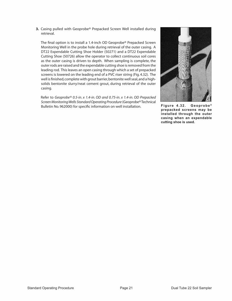
3. Casing pulled with Geoprobe® Prepacked Screen Well installed during retrieval.
The final option is to install a 1.4-inch OD Geoprobe® Prepacked Screen Monitoring Well in the probe hole during retrieval of the outer casing. A DT22 Expendable Cutting Shoe Holder (50271) and a DT22 Expendable Cutting Shoe (50726) allow the operator to collect continuous soil cores as the outer casing is driven to depth. When sampling is complete, the outer rods are raised and the expendable cutting shoe is removed from the leading rod. This leaves an open casing through which a set of prepacked screens is lowered on the leading end of a PVC riser string (Fig. 4.32). The well is finished, complete with grout barrier, bentonite well seal, and a high-solids bentonite slurry/neat cement grout, during retrieval of the outer casing.
Refer to Geoprobe® 0.5-in. x 1.4-in. OD and 0.75-in. x 1.4-in. OD Prepacked Screen Monitoring Wells Standard Operating Procedure (Geoprobe® Technical Bulletin No. 962000) for specific information on well installation. Figure 4 .32 . Geoprobe ®
prepacked screens may be installed through the outer casing when an expendable cutting shoe is used.

Standard Operating Procedure Page 22 Dual Tube 22 Soil Sampler
5.0 REfERENCES
Geoprobe Systems®, Geoprobe® 0.5-in. x 1.4-in. OD and 0.75-in. x 1.4-in. OD Prepacked Screen Monitoring Wells - Standard Operating Procedure. Technical Bulletin No. 962000, 2010.
Geoprobe Systems®, Geoprobe® Screen Point 22 Groundwater Sampler - Standard Operating Procedure. Technical Bulletin No. MK3173, 2010
Geoprobe Systems®, Geoprobe Systems® Tools Catalog, Vol. 6, 2003.

Standard Operating Procedure Page 23 Dual Tube 22 Soil Sampler
Equipment and tool specifications, including weights, dimensions, materials, and operating specifications included in this brochure are subject to change without notice. Where specifications are critical to
your application, please consult Geoprobe® Systems.

A DIVISION OF KEJR, INC.
Corporate Headquarters1835 Wall Street • Salina, Kansas 67401
1-800-GEOPROBE (1-800-436-7762) • Fax (785) 825-2097www.geoprobe.com
®