Embed Size (px)
Citation preview
ACM Reference FormatPottmann, H., Liu, Y., Wallner, J., Bobenko, A., Wang, W. 2007. Geometry of Multi-layer Freeform Structures for Architecture. ACM Trans. Graph. 26, 3, Article 65 (July 2007), 11 pages. DOI = 10.1145/1239451.1239516 http://doi.acm.org/10.1145/1239451.1239516.
Copyright NoticePermission to make digital or hard copies of part or all of this work for personal or classroom use is granted without fee provided that copies are not made or distributed for profi t or direct commercial advantage and that copies show this notice on the fi rst page or initial screen of a display along with the full citation. Copyrights for components of this work owned by others than ACM must be honored. Abstracting with credit is permitted. To copy otherwise, to republish, to post on servers, to redistribute to lists, or to use any component of this work in other works requires prior specifi c permission and/or a fee. Permissions may be requested from Publications Dept., ACM, Inc., 2 Penn Plaza, Suite 701, New York, NY 10121-0701, fax +1 (212) 869-0481, or [email protected].© 2007 ACM 0730-0301/2007/03-ART65 $5.00 DOI 10.1145/1239451.1239516 http://doi.acm.org/10.1145/1239451.1239516
Geometry of Multi-layer Freeform Structures for Architecture
Helmut Pottmann∗
TU WienYang Liu †
TU Wien / Univ. of Hong KongJohannes Wallner‡
TU GrazAlexander Bobenko§
TU BerlinWenping Wang†
Univ. of Hong Kong
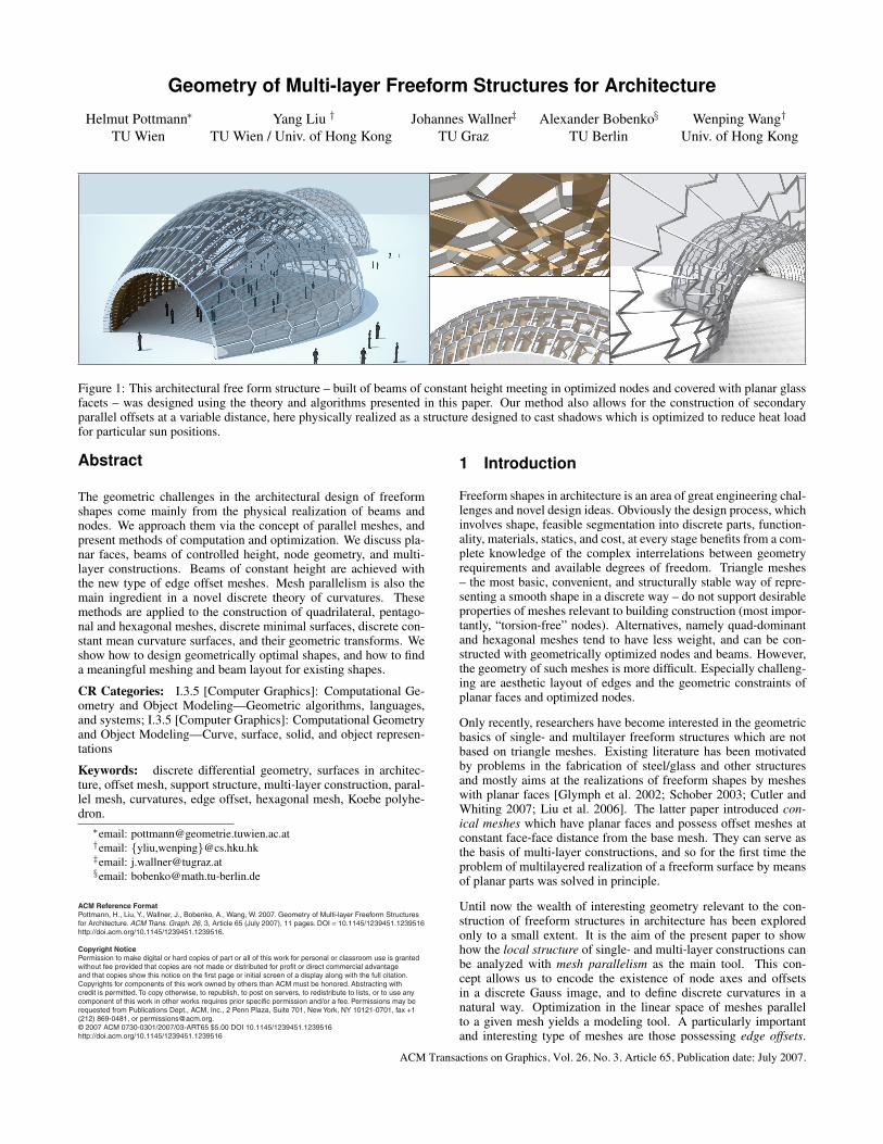
Figure 1: This architectural free form structure – built of beams of constant height meeting in optimized nodes and covered with planar glassfacets – was designed using the theory and algorithms presented in this paper. Our method also allows for the construction of secondaryparallel offsets at a variable distance, here physically realized as a structure designed to cast shadows which is optimized to reduce heat loadfor particular sun positions.
Abstract
The geometric challenges in the architectural design of freeformshapes come mainly from the physical realization of beams andnodes. We approach them via the concept of parallel meshes, andpresent methods of computation and optimization. We discuss pla-nar faces, beams of controlled height, node geometry, and multi-layer constructions. Beams of constant height are achieved withthe new type of edge offset meshes. Mesh parallelism is also themain ingredient in a novel discrete theory of curvatures. Thesemethods are applied to the construction of quadrilateral, pentago-nal and hexagonal meshes, discrete minimal surfaces, discrete con-stant mean curvature surfaces, and their geometric transforms. Weshow how to design geometrically optimal shapes, and how to finda meaningful meshing and beam layout for existing shapes.
CR Categories: I.3.5 [Computer Graphics]: Computational Ge-ometry and Object Modeling—Geometric algorithms, languages,and systems; I.3.5 [Computer Graphics]: Computational Geometryand Object Modeling—Curve, surface, solid, and object represen-tations
Keywords: discrete differential geometry, surfaces in architec-ture, offset mesh, support structure, multi-layer construction, paral-lel mesh, curvatures, edge offset, hexagonal mesh, Koebe polyhe-dron.
∗email: [email protected]†email: {yliu,wenping}@cs.hku.hk‡email: [email protected]§email: [email protected]
1 Introduction
Freeform shapes in architecture is an area of great engineering chal-lenges and novel design ideas. Obviously the design process, whichinvolves shape, feasible segmentation into discrete parts, function-ality, materials, statics, and cost, at every stage benefits from a com-plete knowledge of the complex interrelations between geometryrequirements and available degrees of freedom. Triangle meshes– the most basic, convenient, and structurally stable way of repre-senting a smooth shape in a discrete way – do not support desirableproperties of meshes relevant to building construction (most impor-tantly, “torsion-free” nodes). Alternatives, namely quad-dominantand hexagonal meshes tend to have less weight, and can be con-structed with geometrically optimized nodes and beams. However,the geometry of such meshes is more difficult. Especially challeng-ing are aesthetic layout of edges and the geometric constraints ofplanar faces and optimized nodes.
Only recently, researchers have become interested in the geometricbasics of single- and multilayer freeform structures which are notbased on triangle meshes. Existing literature has been motivatedby problems in the fabrication of steel/glass and other structuresand mostly aims at the realizations of freeform shapes by mesheswith planar faces [Glymph et al. 2002; Schober 2003; Cutler andWhiting 2007; Liu et al. 2006]. The latter paper introduced con-ical meshes which have planar faces and possess offset meshes atconstant face-face distance from the base mesh. They can serve asthe basis of multi-layer constructions, and so for the first time theproblem of multilayered realization of a freeform surface by meansof planar parts was solved in principle.
Until now the wealth of interesting geometry relevant to the con-struction of freeform structures in architecture has been exploredonly to a small extent. It is the aim of the present paper to showhow the local structure of single- and multi-layer constructions canbe analyzed with mesh parallelism as the main tool. This con-cept allows us to encode the existence of node axes and offsetsin a discrete Gauss image, and to define discrete curvatures in anatural way. Optimization in the linear space of meshes parallelto a given mesh yields a modeling tool. A particularly importantand interesting type of meshes are those possessing edge offsets.
ACM Transactions on Graphics, Vol. 26, No. 3, Article 65, Publication date: July 2007.

mi
m′i
mj
m′j
M
M ′
Figure 2: Multi-layer constructions based on the geometric sup-port structure defined by two parallel meshes M , M ′ at approxi-mately constant distance. On the left, the lower layer of the glassroof is suspended from the upper layer which has a structural func-tion. The right hand image shows a rudimentary construction of aglass facade where the closed space between layers has an insulat-ing function.
We show how mesh parallelism establishes a connection betweenmeshes with edge offsets and Koebe polyhedra. Thus the researchpresented here is situated at the meeting point of discrete differ-ential geometry, modeling, geometry processing, and architecturaldesign.
Previous work in discrete differential geometry. Most of thework relevant to the present study concerns quadrilateral mesheswith planar faces, which discretize so-called conjugate curve net-works on surfaces [Sauer 1970]. They are a basic concept inthe integrable system viewpoint of discrete differential geometry[Bobenko and Suris 2005]. Both the circular meshes and the coni-cal meshes of Liu et al. [2006] are special cases which possess par-ticularly nice geometric properties, and which correspond to thoseconjugate curve networks which are also orthogonal, i.e., the princi-pal curvature lines. For convergence of such meshes to the networkof principal curvature lines, see [Bobenko and Suris 2005]. Thefact that principal curvature lines are a concept of Lie sphere geom-etry has a discrete manifestation in the unified treatment of circu-lar and conical meshes as principal meshes of Lie sphere geometry[Bobenko and Suris 2007]. Elementary relations between circularand conical meshes, and meshes which enjoy both properties arediscussed by Pottmann and Wallner [2007]. Special cases of theparallel meshes which are the topic of the present paper have beenconsidered by [Sauer 1970]. Our work on curvature in the presentpaper extends results of Schief [2006], who defined a mean andGaussian curvature for circular meshes via surface areas of discreteoffset surfaces. That method apparently has first been applied tosimplicial surfaces by Nishikawa et al. [1998] in a different context.Another classical definition of the mean curvature through varia-tion of surface area of simplicial surfaces has been investigated byPolthier [2002a]. Discrete minimal surfaces realized as circular andconical meshes are the topic of several contributions (e.g. [Bobenkoand Pinkall 1996; Bobenko et al. 2006]). Attempts to construct dis-crete minimal surfaces with planar quad meshes have been madeby [Polthier 2002b]. The discrete minimal surfaces of [Bobenkoet al. 2006] are particularly interesting because they provide a classof polyhedral surfaces with the edge offset property introduced inthe present paper. It turns out in Section 3.2 that the edge offsetproperty is closely related to results on orthogonal circle patterns[Schramm 1997; Bobenko and Springborn 2004].
Previous work in geometry processing. Only some of the pa-pers mentioned above address the computation of the meshes theydeal with [Bobenko and Springborn 2004; Bobenko et al. 2006; Liuet al. 2006]. The latter paper demonstrates how to design mesheswith planar faces, circular meshes, and conical meshes by subdivi-sion and optimization, and also how to approximate a given shape
by a circular or conical mesh. As input for such mesh optimizationalgorithms any mesh aligned along a network of principal curvaturelines may be used (see e.g. [Alliez et al. 2003; Tong et al. 2006]).Approximation of smooth surfaces by meshes with planar faces,without a focus on support structures and multilayer constructionscan be achieved by variational shape approximation [Cohen-Steineret al. 2004]. Cutler and Whiting [2007] modified this method withregard to aesthetics and architectural design. More generally, var-ious research projects on geometry for architecture in general arepromoted by the Smart Geometry group [SG].
Meshes whose faces are mostly planar 5-gons or 6-gons have cer-tain desirable properties, but such meshes have received consider-ably less attention in the graphics community than triangle meshesand quad meshes. Some notable exceptions are papers on refine-ment processes by Akleman et al. [2005], and on combined primal/dual subdivision [Oswald and Schroder 2003]. However, they donot consider planarity of faces or other aspects relevant to buildingconstruction.
2 Mesh parallelism for architecture
2.1 Motivation and introduction
Glass panels and multilayer metal sheets for roofing structures areplanar as a rule, with only a few exceptions. The reason for this ismostly the prohibitive cost of manufacturing them otherwise. Ob-viously, every implementation of a freeform shape in terms of flatprimitives faces the problem of approximating the given surface bya mesh with planar faces. If triangle meshes are employed, the ge-ometry part of the solution of this problem consists of choosing thevertices and deciding which vertices to connect by edges. If facescan have more than three vertices, this approximation task is not sosimple, because the condition of planar faces is no longer fulfilledautomatically. It should be mentioned that also statics is simplerif we stay with triangle meshes. There are, however, the followingissues which make other solutions attractive:
• In a steel/glass or other construction based on a triangle mesh,typically six beams meet in a node. This means a significantlyhigher node complexity compared to other types of meshes (seeFig. 4, right).
• Experience shows that the per area cost of triangular glass panelsis higher than that of quadrilateral panels. This is mainly due tothe fact that quadrilaterals fill their smallest rectangular bound-ing boxes better than triangles do.
• Generally one aims at less steel, more glass, and less weight,which also suggests the use of non-triangular faces.
• For the actual construction, torsion-free nodes are preferred. Forthis concept, see Figure 4 and the text below. The geometric the-ory however tells us that for triangle meshes in general torsion-free nodes do not exist.
• Apart from trivial cases, triangle meshes do not possess offsets atconstant face-face or edge-edge distance; neither is it possible touse triangle meshes as basis of a multilayer construction whereonly the basic requirement of parallelity of layers is imposed.
This section shows how the concept of parallelism, which applies tomeshes with planar faces, can be used to gain a unified view of theseissues, especially geometrically optimal nodes and offset properties[Brell-Cokcan and Pottmann 2006]. Consider two meshes M andM ′ which are combinatorially equivalent, i.e., there is a 1-1 corre-spondence between vertices and edges. We call the meshes M , M ′
parallel, if corresponding edges are parallel (see Figure 3). Be-fore we consider parallel meshes from the mathematical viewpoint,we first describe some geometric problems connected with discretesurfaces in architecture where this concept occurs naturally.
65-2 • Pottmann et al.
ACM Transactions on Graphics, Vol. 26, No. 3, Article 65, Publication date: July 2007.

M
mi
M ′
m′i
Figure 3: Meshes M , M ′ with planar faces are parallel if they arecombinatorially equivalent, and corresponding edges are parallel.
Multilayer constructions. Structures like those schematically de-picted by Figure 2 include not only one mesh, but several meshes,corresponding to the different layers of the construction. It is natu-ral to demand that meshes which correspond to different layers areparallel.
Geometrically optimal nodes. In the actual realization of a poly-hedral surface M as a steel/glass roof, planar glass panels are heldby prismatic beams following the edges of M (see Fig. 4). A beamis symmetric with respect to its central plane which passes throughthe edge corresponding to the beam. A node corresponds to a ver-tex mi and connects incoming beams in a way which supports theforce flow imposed by the overall statics of the structure. Node con-struction and manufacturing are greatly simplified if there is a nodeaxis Ai, which is contained in the central planes of incoming beams(see Figure 4, left). Figure 4, right, shows the case of a welded nodewhich does not have a node axis. Obviously the handling and man-ufacturing of such ‘nodes with torsion’ is more complicated thanthe case with a node axis. Geometrically, lines Ai passing throughthe vertices mi of a given mesh are a collection of node axes, if andonly if
mimj is an edge =⇒ node axes Ai, Aj are co-planar.
To avoid pathological cases, we forbid that node axes lie in edges.
The following simple but fundamental proposition establishes aproperty of a collection of node axes associated with a mesh M .It relates node axes to an auxiliary mesh M ′ which is parallel to thegiven mesh, and is illustrated by Fig. 4, left.
Proposition 1 If the meshes M , M ′ with vertices mi, m′i (∀ i :
mi 6= m′i) are parallel, then the lines Ai = mi ∨ m′
i serve asnode axes for the mesh M (provided no line Ai contains an edge).
Conversely assume that a simply connected mesh M is equippedwith node axes Ai passing through its vertices mi. Then there ex-ists a mesh M ′ parallel to M , such that Ai is spanned by corre-sponding vertices mi,m
′i.
Proof: This is shown in [Pottmann et al. 2007]. Part (i) is elemen-tary. For part (ii) we start with a vertex m′
i0 ∈ Ai0 and constructfurther vertices of M ′ by the requirement that corresponding edgesof M and M ′ are parallel, and that m′
i ∈ Ai for all i. �
Geometric support structure. There is a point of view whichunifies the different cases where parallel meshes occur – regard-less of whether a parallel mesh is physically realized, or is onlyused in the definition of node axes. This point of view is that weemphasize the construction elements which connect different lay-ers – physically present or not – and which are transverse to themesh M under consideration. In Figure 2, right, these construc-tion elements are the glass panels which connect the two parallelmeshes M , M ′. In Figure 4, left, these construction elements arethe beams. We shrink those elements until they have zero width(this is schematically indicated in Fig. 4, left). They then become
Ai
mimimimimimimimimimimimimimimimimi m′im′im′im′im′im′im′im′im′im′im′im′im′im′im′im′im′i
MMMMMMMMMMMMMMMMMM ′M ′M ′M ′M ′M ′M ′M ′M ′M ′M ′M ′M ′M ′M ′M ′M ′
Figure 4: Left: This figure shows nodes, supporting beams, and theunderlying geometric support structure of a steel/glass construction,based on a mesh M (vertices mi) and its parallel mesh M ′ (verticesm′
i). All beams are symmetric with respect to their central plane(blue); at an optimized (torsion-free) node mi the central planesof supporting beams pass through the node axis Ai = mi ∨ m′
i.Right: A node without axis, with geometric torsion.
planar quadrilaterals transverse to the mesh M , passing through theedges of M . Those transverse quads which are adjacent to a nodemi, have a common edge which lies in the node axis Ai. Such acollection of quads is called a geometric support structure of themesh M (see Figures 1, 2, 4, 6, 13, and 14).
Obviously, a collection of node axes for M almost uniquely definesthe quads of a geometric support structure for M – the only degreeof freedom left is the quad boundaries opposite to the edges of M .By Proposition 1, any geometric support structure joins the edges ofM with the respective corresponding edges of a mesh M ′ parallelto M . Every node axis Ai joins corresponding vertices mi, m′
i.
Specific problems considered in this paper. We are going todiscuss meshes with certain geometric properties relevant to archi-tectural design, especially support structures. An important prop-erty of this kind is that a mesh possesses a support structure whosebeams are of constant height – this is the class of edge offset meshesdefined later. Generally speaking, the more properties we require amesh to have, the fewer degrees of freedom are available. We there-fore encounter the following problems:
• The approximation problem. Is it possible to approximate a givenshape by a mesh contained in a specific class of meshes? Forexample, this is pssible for the conical quad meshes, as shownby Liu et al. [2006], but not for the quad meshes with the edgeoffset property. However we shall see that we can approximatearbitrary surfaces if we relax the requirement of constant heighta little bit.
• The design problem. How can we explore or even completelydescribe the set of meshes with a specific geometric property?This question is especially important in cases where the approx-imation problem is not solvable. For example, we will intro-duce some geometric transformations which change shape butpreserve the edge offset property.
2.2 Basics of mesh parallelism
Mesh parallelism and the spaces C(M ) and P(M ). A meshM is represented by the list (m1, . . . .mN ) ∈ R3N of verticesand the mesh combinatorics, i.e., the information which verticesbelong to common edges and faces. We use C(M ) to denote the lin-ear 3N -dimensional space of meshes combinatorially equivalent toM . If M ′, M ′′ have the same combinatorics, a linear combinationλ′M ′ + λ′′M ′′ is defined vertex-wise; this operation correspondsto the linear combination of vectors in R3N .
Geometry of Multi-layer Freeform Structures for Architecture • 65-3
ACM Transactions on Graphics, Vol. 26, No. 3, Article 65, Publication date: July 2007.

M
M ′
M ′′
M ′′′ = 2590
M + 4490
M ′ + 2190
M ′′
Figure 5: The set P(M ) of meshes parallel to a given mesh M isa linear space and can be explored by a linear blend of some of itselements.
Meshes M , M ′ are parallel, if M ′ ∈ C(M ) and correspondingedges are parallel (see Figures 3 and 5). We use that definitiononly if the faces of M are planar. Clearly then corresponding facesof M and M ′ lie in parallel planes (parallelity of planes alone issufficient to guarentee parallelity of edges, if no pair of adjacentfaces are co-planar). We denote the set of meshes parallel to Mby P(M ). To avoid pathological cases we require that the meshM which defines the space P(M ) has only nonzero edges. Trivialways of producing meshes parallel to M are to translate and scaleM . Since triangles with parallel edges are scaled copies of eachother, two parallel triangle meshes are scaled copies of each other[Pottmann et al. 2007]. This is the reason why we do not considertriangle meshes in the rest of the paper.
Suppose M ′, M ′′ ∈ P(M ). Then, for each edge mimj , the vec-tors m′
i−m′j , m′′
i −m′′j are multiples of mi−mj . It follows that
any expression (λ′m′i +λ′′m′′
i )−(λ′m′j +λ′′m′′
j ) is a multiple ofmi −mj . This shows that the linear combination λ′M ′ + λ′′M ′′
is also parallel to M , so P(M ) is a linear subspace of C(M ). Thezero vector of both P(M ) and C(M ) is the mesh o = 0 · M , allof whose vertices coincide with the origin of the coordinate sys-tem. Linear blending between three meshes in the space P(M ) isillustrated by Figure 5.
The space P(M ) does not only contain ‘nice’ meshes. We may seevarious undesirable effects such as unevenly distributed faces, sharpedges of regression, or overlapping regions. Nevertheless, it is boththeoretically and practically useful to have the entire space P(M )at our disposal. Even visually unpleasant meshes in P(M ) willturn out to be helpful in the computation of optimal beam layouts(see Fig. 14d).
Computing in the space of parallel meshes. As P(M ) is a lin-ear space, it is important to determine a basis. We observe that amesh M ′ ∈ C(M ) is contained in P(M ) if and only if
mimj is an edge =⇒ m′i −m′
j = λij(mi −mj). (1)
We can therefore determine P(M ) as the solution space of the sys-tem of equations
(m′i −m′
j)× (mi −mj) = 0 for all edges mimj . (2)
A rough count of degrees of freedom (one d.o.f. per edge, twoclosure conditions per face, 3 d.o.f. for the translations in space)shows that e.g. for open meshes we can expect dimP(M ) =# edges − 2 × # faces + 3. The actual solution of (2) is done viaSVD. Thresholding of small singular values is supported by an apriori estimate for dimP(M ).
Once a basis is available, the minimization of linear and quadraticfunctionals (e.g. a fairness functional) under constraints (like fixedpoints) and linear side conditions (like edge length inequalities)presents no problems.
3 Offset meshes
Meshes are offsets of each other, if they are parallel, and in additiontheir distance from each other is constant throughout the mesh. Thisnotion is similar to the concept of smooth offset surfaces [Maekawa1999], but in contrast to the smooth case, for meshes there are var-ious different definitions of distance. Consequently, there are alsovarious different notions of offset mesh. Two of them, face offsetsand edge offsets are relevant to problems of architectural design offreeform surfaces considered in this paper.
For multilayer constructions (cf. Figure 2) it is natural to requirethat the distance of corresponding faces is constant. Parallel mesheswith this property (face offsets) are the topic of [Liu et al. 2006].
Another type of offset occurs when we employ parallel meshes forthe layout of beams in a steel/glass construction based on a givenmesh M . The beams are a physical realization of a geometricsupport structure which connects two parallel meshes M and M ′.If the distance of corresponding edges in M and M ′ is constantthroughout the mesh, then beams of constant height are perfectlyaligned on both the upper (outer) and the lower (inner) side of theconstruction, provided that the mesh is convex (see Figure 6).
If, on the other hand, the distance of corresponding edges in M andM ′ is not the same throughout the mesh, then one could still usebeams with the same cross-section throughout the mesh, but thesebeams will not be aligned on both sides (see Figure 7). Still, if Mand M ′ are at almost constant edge-edge distance, a physical re-alization may use beams of the same cross-section throughout themesh, without too much misalignment being visible. As exact dis-tance requirements are sometimes hard or impossible to fulfill, weconsider offsets at an exactly constant distance (in this section) aswell as offsets at approximately constant distance (in Section 4).
Figure 6: This construction (a detail of Fig. 1) is based on an edgeoffset mesh and has beams of constant height. In the positivelycurved areas, edges (red) of beams with rectangular cross-sectionhave an exact intersection at the nodes, which follows from Prop. 3.
(a)(a)(a)(a)(a)(a)(a)(a)(a)(a)(a)(a)(a)(a)(a)(a)(a) (b)(b)(b)(b)(b)(b)(b)(b)(b)(b)(b)(b)(b)(b)(b)(b)(b) (c)(c)(c)(c)(c)(c)(c)(c)(c)(c)(c)(c)(c)(c)(c)(c)(c)
Figure 7: This geometric support structure is defined by two paral-lel meshes which are not of constant edge-edge distance. We nev-ertheless employ beams of constant height to physically realize thatsupport structure. The resulting misalignment is not visible fromthe outside (a), hardly visible from the beams’ mid-sections lyingin the respective central planes (b), but is clearly visible from the in-side (c). Still, nodes have no torsion and symmetry planes of beamsintersect in the node axis.
65-4 • Pottmann et al.
ACM Transactions on Graphics, Vol. 26, No. 3, Article 65, Publication date: July 2007.

3.1 Types of exact offset meshes
Recall that a mesh M ′ ∈ P(M ) at constant distance from M isan offset of M . Different ways to define the precise meaning of“dist(M , M ′) = d” lead to different kinds of offsets:
• vertex offsets: The distance of corresponding vertices mi, m′i
equals a constant d, which does not depend on the vertex.• edge offsets: The distance of corresponding parallel edges (actu-
ally, lines which carry those edges) does not depend on the edgeand equals d.
• face offsets: The distance of faces (actually, planes which carryfaces) is independent of the face and equals d.
Discrete Gauss images. If p is a point of a smooth surface and nis the unit normal vector there, then p′ = p + dn would be a pointof an offset surface at distance d. If p,p′ are given, we can recoverthe unit normal vector by n = (p′−p)/d. If M ′ is an offset meshof M we can mimick this construction and define a discrete Gaussimage mesh S := (M ′−M )/d, whose vertices si = (m′
i−mi)/dcan be regarded as discrete normal vectors.
Proposition 2 Consider a mesh M , its offset mesh M ′ at distanced, and define the Gauss image mesh S = (M ′ − M )/d. Then thefollowing is true:
1. M ′ is a vertex offset of M ⇐⇒ the vertices of S are con-tained in the unit sphere S2. If S is a quad mesh and no edgesdegenerate, then M has a vertex offset if and only if M is acircular mesh, i.e., each face has a circumcircle.
2. M ′ is an edge offset of M ⇐⇒ the edges of the Gauss imagemesh S are tangent to S2.
3. M ′ is a face offset of M ⇐⇒ the faces of the Gauss imagemesh S are tangent to S2. A mesh has a face offset if and onlyif it is conical, i.e., the faces around a vertex are tangent to acone of revolution.
So in all three cases we have the equivalence dist(M , M ′) = d⇐⇒ dist(S ,o) = 1, which means that the vertices, or the edges,or the faces of S are at distance 1 from the origin.
Proof: The equivalence dist(M ′, M ) = d ⇐⇒ dist(S ,o) = 1is elementary. The statements about circular and conical meshesare reviewed in [Pottmann and Wallner 2007]. �
This relation between a pair of offset meshes M , M ′ and the Gaussimage mesh S is illustrated by Figure 8. Proposition 2 has an im-portant consequence: If the mesh M has an offset mesh at constantvertex/edge/face distance, then every mesh parallel to M has thisproperty. This is because the Gauss image mesh S ∈ P(M ) can
S2
S
M ′ = M + dS
M
Figure 8: A mesh M with an edge offset mesh M ′ at distance dhas a parallel mesh S = (M ′ −M )/d whose edges are tangent tothe unit sphere S2. The faces of S intersect S2 in a circle packing,cf. Section 3.2.
be used to construct an offset not only for M , but for any furthermesh in P(M ). Another observation will be important later: Wecan first construct a mesh whose vertices/edges/faces are at distance1 from the origin. Then any mesh M ∈ P(S) has offset meshesM ′ = M + dS .
3.2 Meshes with edge offsets
We are interested in meshes which have edge offsets (EO meshes)because they can be built with beams of constant height meeting atthe nodes in a geometrically optimal way (see Figure 6). Proposi-tion 2 mentioned that a mesh M has an edge offset mesh, if there isa mesh S parallel to M whose edges are tangent to the unit sphere.The following paragraphs deal with the interesting mathematicaltheory of EO meshes, with a focus on the geometry of S .
Proposition 3 If a mesh M has an edge offset M ′, then for eachvertex mi of M , the edges emanating from mi are contained in acone of revolution Γi. The node axis Ai spanned by correspondingvertices mi ∈ M , m′
i ∈ M ′ is the axis of the cone Γi.
Proof: The statement about cones is true for the mesh M if andonly if it is true for at least one mesh in P(M ) which does not havezero edges (because corresponding edges are parallel). It is thussufficient to show it for the Gauss image mesh S = (M ′ −M )/d,where d = dist(M , M ′). According to Proposition 2, the edgesof S are tangent to the unit sphere S2 (see Figure 8 and especiallyFigure 9). Obviously, all lines emanating from a vertex si whichtouch S2 lie in a cone of revolution eΓi, so the statement is true forS . Consequently it is true for M . The axis of eΓi passes throughthe origin, so it is parallel to the vector si. It follows that the axisAi of the cone Γi associated with the vertex mi contains the pointm′
i = mi + dsi. �
SSSSSSSSSSSSSSSSS
eeeeeeeeeeeeeeeee
sisisisisisisisisisisisisisisisisi
sjsjsjsjsjsjsjsjsjsjsjsjsjsjsjsjsj
FkFkFkFkFkFkFkFkFkFkFkFkFkFkFkFkFk
FlFlFlFlFlFlFlFlFlFlFlFlFlFlFlFlFl
tetetetetetetetetetetetetetetetete
csicsicsicsicsicsicsicsicsicsicsicsicsicsicsicsicsi
csjcsjcsjcsjcsjcsjcsjcsjcsjcsjcsjcsjcsjcsjcsjcsjcsj
cFkcFkcFkcFkcFkcFkcFkcFkcFkcFkcFkcFkcFkcFkcFkcFkcFk
eΓieΓieΓieΓieΓieΓieΓieΓieΓieΓieΓieΓieΓieΓieΓieΓieΓi
sisisisisisisisisisisisisisisisisi
S2
Figure 9: A Koebe polyhedron and related circles and cones.
EO meshes and Koebe polyhedra. A mesh S with planar faceswhose edges e touch S2 in points te (a so-called Koebe poly-hedron) has very interesting geometry [Bobenko and Springborn2004; Ziegler 1995]. Each face F intersects S2 in a circle cF whichtouches the boundary edges of F from the inside (see Figures 8 and9). For any vertex si, the vertex cone eΓi touches the unit sphere in acircle csi . Obviously the edge e has a point of tangency te with S2,and two circles of either type pass through te. Circles of the sametype touch each other, and circles of different types intersect at 90degrees. The computation of such circle patterns via minimizationof a convex function is known [Bobenko and Springborn 2004] andeven possible on-line [Sechelmann 2006]. Closed Koebe polyhe-dra are uniquely determined by their combinatorics up to a Mobiustransformation (i.e., a projective mapping which transforms S2 intoitself). For open polyhedra there is an additional degree of freedomfor each boundary vertex.
Geometry of Multi-layer Freeform Structures for Architecture • 65-5
ACM Transactions on Graphics, Vol. 26, No. 3, Article 65, Publication date: July 2007.

S S ′
MMMMMMMMMMMMMMMMM
M ′
Figure 10: Creation of the mesh M ′ which Figure 1 is based on. This example demonstrates that meshes with properties interesting from themathematical viewpoint can yield aesthetically pleasing results; and that a designer has access to additional degrees of freedom by applyingsome nonstandard geometric transformations. Here we start with the Koebe polyhedron S and construct the mesh M which is of constantmean curvature with respect to S (the Gauss mapping σ : M → S has an overfolding, with the inflection circle on M corresponding tothe apparent boundary of S ). Applying a Laguerre transformation results in the EO mesh M ′, which has the Gauss image mesh S ′. ThisL-transform was found interactively.
3.3 Designing with EO meshes
The edge offset property is rather restrictive. Quad-dominant mesh-es which have vertex or face offsets (i.e., the circular and conicalmeshes), are capable of approximating arbitrary shapes. This is nolonger the case with EO meshes.
Computing EO meshes from Koebe polyhedra. We may use thefollowing general procedure when designing a mesh M with theedge offset property: First we determine the combinatorics of themesh and compute a Koebe polyhedron S with that combinatorics,using the procedure of [Bobenko and Springborn 2004]. The meshM we are looking for is then found within the space P(S), e.g. byoptimization. An example of this is shown by Figure 11, where Sis a Koebe polyhedron with pentagonal faces and M is found byminimizing the fairness functional fLaplacian defined by
fLaplacian(M ) =X
vertices mi
`mi −
1
deg(mi)
Xmj∈star(mi)
mj
´2, (3)
under appropriate sign constraints for the factors λij of Equ. (1)(see the figure caption for more details). Once an EO mesh is found,we may apply geometric transformations to it – this is the topic ofthe next paragraph. It is obvious that these methods are not usefulfor geometric modeling in the usual sense, but only for form findingpurposes.
Laguerre transformations of EO meshes. From the variousequivalent descriptions of Laguerre geometry [Cecil 1992], the fol-lowing, which employs the spheres of R3 as basic elements, is per-haps shortest: A sphere S with center (m1, m2, m3) and signedradius r is identified with the point xS = (m1, m2, m3, r) ∈ R4.We think of normal vectors of spheres pointing to the outside if andonly if r > 0. Points are spheres of zero radius. An L-transforma-tion then has the form xS 7→ A · xS + a, where a ∈ R4 and A isa 4× 4 matrix with AT JA = J and J = diag(1, 1, 1,−1). EveryEuclidean transform permutes the set of spheres and can be writ-ten as an L-transform. Another simple example of an L-transform(A = I4 and a = (0, 0, 0, d)) is the offsetting operation whichincreases the radius by the value d. It is well known that the setof spheres tangent to an oriented cone of revolution is mapped byany L-transform α to a set of the same type [Cecil 1992]. Thus, anoriented cone of revolution Γ becomes an entity of Laguerre geom-etry: Take two spheres S1, S2 tangent to Γ and define α(Γ) to betangent to the spheres α(S1), α(S2). After these preparations wecan state:
Proposition 4 An L-transformation maps an edge offset mesh Mto another edge offset mesh M ′, if both are seen as the respectivecollection of vertex cones Γi, Γ′
i according to Proposition 3.
The proof is not difficult, but exceeds the scope of this paper. Weuse Proposition 4 for the modification of edge offset meshes. Anexample is furnished by the mesh Figure 1 is based on; the trans-formation we use is illustrated by Figure 10.
Possible shapes of EO meshes (quad and hex mesh cases).For a mesh M with the edge offset property, the Gauss image meshS is a Koebe polyhedron. Bobenko et al. [2006] show that in case ofquad meshes, S is a so-called s-isothermic mesh and thus the meshM is a discrete variant of a curvature line parametrization whoseGauss image is an isothermic curve network. Such “L-isothermicsurfaces” are mentioned by Blaschke [1929], but not much seems tobe known about their shapes. Likewise, the description of the pos-sible shapes obtainable by quadrilateral EO meshes is an unsolvedproblem at the present time.
Hexagonal meshes, which here is a synonym for meshes with pla-nar faces and vertices of valence three, have better approximationproperties (cf. e.g. [Cutler and Whiting 2007]). In order to createa hexagonal EO Mesh M which approximates a given surface Φ,we could start with any Koebe polyhedron S which is a hexagonalmesh (cf. Figures 10 and 18) and determine the vertices mi of M asfollows: Parallel translate the three planes which are adjacent to thevertex si in the mesh S so that they touch Φ, and intersect them. By
M
S
Figure 11: Edge offset mesh of negative curvature. The mesh Mwith pentagonal faces has a parallel mesh S whose edges are tan-gent to the unit sphere, so M has the edge offset property. Cor-responding edges of M and S are parallel, but the correspondenceis orientation-reversing for some edges. The general pattern whichedges keep their orientation and which do not is indicated by theschematic diagram. The mesh S is a Koebe polyhedron; M wasfound by minimizing the Laplacian energy of Equation (3) in thespace P(S), under appropriate sign constraints on the coefficientsλij of Equation (1).
65-6 • Pottmann et al.
ACM Transactions on Graphics, Vol. 26, No. 3, Article 65, Publication date: July 2007.

construction, M has the edge offset property and the planes whichcarry its faces touch Φ. Unfortunately it is apparently difficult toguarantee that M is a nice polyhedral surface without self-intersec-tions, so much work remains to be done before such a procedurecan be used as an effective design tool. The present paper does notenter the topic of approximating general surfaces with hex meshes.
4 Optimizing support structures
In view of Proposition 2 we cannot expect a general mesh withplanar faces which is neither circular nor conical to have vertex off-sets or face offsets. The class of meshes with edge offsets is evenmore restricted, as discussed in Sections 3.2 and 3.3. Thereforethe problem of constructing offsets at approximately constant dis-tance is important. This section first discusses such approximateoffset meshes from a theoretical viewpoint, and then shows howto compute them by minimizing a quadratic function in the spaceP(M ). We also treat the problem of finding a mesh with planarfaces which approximates a given shape in the first place. Thiscompletes the processing pipeline from shape to mesh, and furtherto support structure. The last part of this section deals with morecomplex optimization problems.
4.1 Approximate offsets
The mesh M ′ which is parallel to the mesh M is said to be an ap-proximate offset of M , if M ′ = M + dS , where S ∈ P(M ) is amesh which approximates the unit sphere. We say that the distanceof M ′ from M is approximately constant, and that S is an approx-imate Gauss image of M . As there are different kinds of (exact)Gauss image anyway, we will drop the attribute ‘approximate’ andsimply speak of a Gauss image. The vertex si of S correspondingto a vertex mi of M is considerd as an approximate normal vectorfor the vertex mi. Then the approximate offset at distance d hasvertices mi +dsi, which is directly analogous to the previous nota-tion (see Figure 12). We use the symbol σ : M → S for the naturalcorrespondence between the meshes M and S (σ is the Gauss map-ping). The computation of an approximate Gauss image for a givenmesh with planar faces is discussed in Sections 4.2 and 4.3 below.
S = σ(M )S = σ(M )S = σ(M )S = σ(M )S = σ(M )S = σ(M )S = σ(M )S = σ(M )S = σ(M )S = σ(M )S = σ(M )S = σ(M )S = σ(M )S = σ(M )S = σ(M )S = σ(M )S = σ(M ) M + dSM + dSM + dSM + dSM + dSM + dSM + dSM + dSM + dSM + dSM + dSM + dSM + dSM + dSM + dSM + dSM + dS
M
mj
mj + dsj
si
sj
mimi + dsi
Figure 12: This figure illustrates how we assign a geometric sup-port structure to a given mesh M and thus make it buildable withoptimized nodes and controlled beam heights. Optimization in thespaceP(M ) yields a parallel mesh S approximating the unit sphereS2, thus defining offsets M ′ = M + dS at approximately constantdistance d. Here S has an overfolding due to a change in the signof curvature in M , and is contained in the layer between radii 0.98and 1.04.
4.2 Offset meshes by optimization in P(M )
We approach the problem of computing offsets at approximatelyconstant distance as follows: For a given mesh M we must find amesh S ∈ P(M ) which approximates the unit sphere (S is a Gauss
image of M ). We can convert this problem into minimization of aquadratic functional: For each face F , we have its normal vectornF , and a vertex mi(F ) ∈ F . For each vertex mi, we estimate aunit normal vector eni. The vertex of S corresponding to the vertexmi is denoted by si. We set up the functionals
ffaces =X
faces F
(nF · (si(F )−nF ))2, fvert =X
vertices mi
(si − eni)2,
and minimize a linear combination of ffaces, fvert, and the fairnessfunctional fLaplacian of Equation (3). The aims fvert → min andffaces → min express the requirement that indeed the mesh S is an(approximate) Gauss image of M . Results are shown by Figures 12and 13. Also the processing pipeline described in Section 4.3 usesthis construction (cf. Figure 14). We may assign a low weight to thefairness term for S , as a lack of fairness for S is hardly noticeablein the support structure (Fig. 14d). It may be more important thatbeam heights are approximately constant.
4.3 A processing pipeline from shape to beam layout
Section 4.2 describes how we can find, for a given mesh M withplanar faces, an approximate offset, which can be used e.g. for thedefinition of beams of approximately constant heights. This sectionconsiders also the problem which in the overall processing pipelinecomes earlier: How to find a mesh which has planar faces and ap-proximates a given shape.
Liu et al. [2006] compute a quad-dominant mesh with planar facesfor a given surface by optimizing a mesh which follows a networkof conjugate curves (of which Figures 14, a–c show some exam-ples). Obviously the angle of intersection of such curves is im-portant for the quality of the mesh, but for negatively curved sur-faces it is not guaranteed that a network of conjugate curves hasonly transverse intersections. The special case of principal curva-ture lines has an intersection angle of 90◦ throughout the network.However, we would like to have more degrees of freedom at ourdisposal when choosing the curve network.
Figure 14 illustrates our approach to this problem. We apply anaffine transformation α to the given surface, compute principal cur-vature lines for the transformed surface, and transform them backwith α−1. Conjugacy of curves is invariant with respect to affinetransformations, and the intersection angle of the resulting curvesis close to 90◦ if α is close to the identity transformation. So weare able to create a number of suitable curve networks simply bychoosing different affine mappings (see Figures 14, a–c).
We then lay out a quad-dominant mesh along a curve networkwhich fits the design intent best, e.g. has few singularities, or hasthe singularities in the right places (we choose Figure 14c). Thismesh is optimized such that its faces become planar, using theprocedure employed by Liu et al. [2006]. Having computed themesh M , we next need to find a support structure with beams ofapproximately constant height. This is done by finding a meshS ∈ P(M ) which approximates S2, using the minimization pro-cedure described in Section 4.2. A result is shown by Figure 14d.The geometric support structure which is bounded by the meshesM and M ′ = M + dS is illustrated by Figure 14e.
4.4 Other ways of optimization
Combined optimization of mesh and Gauss image. Section 4.2discussed the problem of computing a geometric support structure– or an approximate Gauss image S – for a given mesh M , and inthat section we described how to solve that problem by quadraticoptimization in the space P(M ). Here we go one step further andoptimize both M and S at the same time.
Geometry of Multi-layer Freeform Structures for Architecture • 65-7
ACM Transactions on Graphics, Vol. 26, No. 3, Article 65, Publication date: July 2007.

(a) (b) (c) (d)(d)(d)(d)(d)(d)(d)(d)(d)(d)(d)(d)(d)(d)(d)(d)(d)
Figure 13: This figure illustrates that finding a support structure according to the method of Section 4.2 can be done with little change in theoriginal mesh. (a) a mesh M created by subdivision. (b) In order to create a geometric support structure with nice offset properties, we firstfollow [Liu et al. 2006] and make the mesh conical by perturbing vertices. As the intersection angles of mesh polylines in M are far from 90degrees, the optimized mesh deviates much from M . (c) If M is optimized to become planar, not necessarily conical, the deviations from theoriginal mesh are small. (d) We apply our procedure for creating a support structure with approximately constant beam heights.
(a)(a)(a)(a)(a)(a)(a)(a)(a)(a)(a)(a)(a)(a)(a)(a)(a) (b)(b)(b)(b)(b)(b)(b)(b)(b)(b)(b)(b)(b)(b)(b)(b)(b) (c)(c)(c)(c)(c)(c)(c)(c)(c)(c)(c)(c)(c)(c)(c)(c)(c) (d)(d)(d)(d)(d)(d)(d)(d)(d)(d)(d)(d)(d)(d)(d)(d)(d)
S
(e)(e)(e)(e)(e)(e)(e)(e)(e)(e)(e)(e)(e)(e)(e)(e)(e)
Figure 14: Meshing and construction of a support structure with optimized nodes for a given architectural freeform design. (a)–(c). A studyof different conjugate curve networks is performed. We lay out a quad mesh M along the network in (c) and use the method of [Liu et al.2006] to optimize M such that its faces become planar. M is shown in subfigure (e). (d) We recompute a Gauss image S of M whichapproximates the unit sphere S2. (e) S leads to a support structure with optimized nodes and approximately equal beam heights for M .
The purpose of this computation is to design a mesh which has off-set or curvature properties useful for architectural design. We knowthat any such mesh has to approximately follow a network of prin-cipal curves. We start with a mesh with this property and set upan optimization problem as follows. We consider the functionalsfclose,1 :=
Pi dist(mi, Φ)2 and fclose,2 :=
Pi ‖si‖2, which ex-
press proximity of the vertices of M , S to their respective referencesurfaces Φ, S2; further, the functional
fpar :=X
edges mimj
‖ mi −mj
‖mi −mj‖× (si − sj)‖2,
which expresses parallelity of meshes M and S ; the fairness func-tionals fLaplacian(M ), fLaplacian(S) according to Equation (3); andthe functional fdet of [Liu et al. 2006] which expresses planarity ofthe mesh M . We then use a penalty method to minimize a linearcombination of the functionals above. Other functionals may be in-cluded. An example which includes a functional aiming at constantmean curvature is presented in Section 5 (Figure 19).
Methods of optimization and numerics. The solution of thenonlinear optimization problems which arise when minimizing thefunctionals above, under the side condition of planarity of facesand parallelity of meshes, usually is difficult. We have employed apenalty method analogous to the mesh optimization procedure de-scribed by [Liu et al. 2006]; actually the problems to be solved inthe present context are similar to that paper. In order to minimizea functional F under k different constraints G1 = 0, . . . , Gk = 0,we consider the auxiliary minimization problem λF +
PµjG
2j →
min: For stable convergence, λ has a higher value at the beginning,and tends to zero as optimization progresses. The unconstrainedminimization problem λF +
PµjG
2j → min can effectively be
solved by the Gauss-Newton method with LM regularization [Kel-ley 1999]. In our case, F is a linear combination of fclose,1, fclose,2,fLaplacian(M ), fLaplacian(S), while the constraints are given by fdet
and fpar. This method usually requires user interaction when bal-ancing the weights of the individual functionals.
Translating the Gauss image. We want to mention a simple factwhich nevertheless has an interesting application: If S is a Gaussimage for the mesh M , then formally any translate S ′ = S + xis a valid Gauss image, simply because it was never specified howwell S ′ must approximate the unit sphere, and meshes S ′ and Mare parallel. It is a different question if we can still call the verticesof S ′ normal vectors of the polyhedral surface M without violatinggeometric intuition, but if x is small, we surely can (see Fig. 15).
Figure 1 shows an architectural design based on a mesh M and twodifferent geometric support structures: One is defined by a Gaussimage mesh S whose edges are tangent to S2. It is used to createthe supporting beams (then of constant height). The other one isbased on the Gauss image S ′ = S +x, and is physically realized asshading elements. The vector x has been found by subjecting it tooptimization: We select parallel light (for particular sun positions)and compute x such that the total area of shadow cast by the shadingelements is maximal, under the constraint ‖x‖ ≤ 0.99.
M M
Figure 15: These two systems of ‘approximate normal vectors’ ofa mesh M are defined by a Gauss image S , whose edges are tan-gent to S2 (left image), and the Gauss image S + x (right image).They correspond to the two different support structures employedin Fig. 1.
65-8 • Pottmann et al.
ACM Transactions on Graphics, Vol. 26, No. 3, Article 65, Publication date: July 2007.

5 Curvatures in meshes with planar faces
It has been observed many times that properties of smooth or dis-crete surfaces which are interesting from the mathematical view-point often lead to very aesthetic figures [Sullivan 2005]. This iseven more important in our current work which focuses on archi-tecture and design. Therefore the aim of this section on curvaturesis not only to create geometric functionals useful for smoothing andother optimization tasks, but to lay the foundations for interactivedesign and form finding tools. We want to demonstrate that the ear-lier theory developed in the paper, namely offset properties and sup-port structures based on parallelism, is compatible with the secondone, namely the definition of curvatures based on mesh parallelism.Not only they are compatible, but surfaces of constant or vanishingmean curvature, as well as other special surfaces, serve as basis ofarchitectural designs with functional properties.
Preparation: Mixed areas and Steiner’s formula. Assume thatP = (p0, . . . ,pk−1) and Q = (q0, . . . ,qk−1) are planar poly-gons whose corresponding edges are parallel (‘parallel polygons’).Then also the polygon P + dQ = (p0 + dq0, . . . ) is par-allel to P and Q. We are interested in the oriented area ofP + dQ, with the orientation defined by a normal vector n ofthe plane which contains P . Its computation is based on the for-mula 1
2det(b− a, c− a,n) for the area of a triangle with vertices
a,b, c, lying in a plane with unit normal vector n. It follows thatarea(P + dQ) = 1
2
Pk−1i=0 det(pi + dqi,pi+1 + dqi+1,n), with
indices modulo k. This implies that
area(P + dQ) = area(P ) + 2d area(P, Q) + d2 area(Q), with
area(P, Q) =1
4
k−1Xi=0
[det(pi,qi+1,n) + det(qi,pi+1,n)]. (4)
The computation so far is well known – area(P, Q) denotes themixed area of polygons P and Q in the terminology of convex ge-ometry [Schneider 1993].
PPPPPPPPPPPPPPPPP
p0p0p0p0p0p0p0p0p0p0p0p0p0p0p0p0p0 p1p1p1p1p1p1p1p1p1p1p1p1p1p1p1p1p1
p2p2p2p2p2p2p2p2p2p2p2p2p2p2p2p2p2
p3p3p3p3p3p3p3p3p3p3p3p3p3p3p3p3p3
QQQQQQQQQQQQQQQQQ
q0q0q0q0q0q0q0q0q0q0q0q0q0q0q0q0q0 q1q1q1q1q1q1q1q1q1q1q1q1q1q1q1q1q1
q2q2q2q2q2q2q2q2q2q2q2q2q2q2q2q2q2q3q3q3q3q3q3q3q3q3q3q3q3q3q3q3q3q3
ooooooooooooooooo
P+0.4QP+0.2QPP−0.2QP−0.4QP−0.6Q
P+0.4QP+0.2QPP−0.2QP−0.4QP−0.6Q
P+0.4QP+0.2QPP−0.2QP−0.4QP−0.6Q
P+0.4QP+0.2QPP−0.2QP−0.4QP−0.6Q
P+0.4QP+0.2QPP−0.2QP−0.4QP−0.6Q
P+0.4QP+0.2QPP−0.2QP−0.4QP−0.6Q
P+0.4QP+0.2QPP−0.2QP−0.4QP−0.6Q
P+0.4QP+0.2QPP−0.2QP−0.4QP−0.6Q
P+0.4QP+0.2QPP−0.2QP−0.4QP−0.6Q
P+0.4QP+0.2QPP−0.2QP−0.4QP−0.6Q
P+0.4QP+0.2QPP−0.2QP−0.4QP−0.6Q
P+0.4QP+0.2QPP−0.2QP−0.4QP−0.6Q
P+0.4QP+0.2QPP−0.2QP−0.4QP−0.6Q
P+0.4QP+0.2QPP−0.2QP−0.4QP−0.6Q
P+0.4QP+0.2QPP−0.2QP−0.4QP−0.6Q
P+0.4QP+0.2QPP−0.2QP−0.4QP−0.6Q
P+0.4QP+0.2QPP−0.2QP−0.4QP−0.6Q
Figure 16: Parallel polygons with vertices pi, qi, and pi + dqi.
Curvatures of faces. Curvatures in polyhedral surfaces can be de-fined in different ways. One may be guided by the idea that a dis-crete surface approximates a smooth one, and define a curvatureby way of numerical differentiation. Another method is to observerelations between curvatures and geometric properties in smoothsurfaces, and to postulate an analogous relation for the discretecase, like in the definition of the mean curvature vector by Polthier[2002a] as the gradient of the area functional for triangle meshes.In our setting we consider the variation of surface area when pass-ing from a surface Φ to an offset surface Φd: Each point x ∈ Φ ismoved to x + dn(x), where “n” is the field of unit normal vectors.Then the surface area changes according to
area(Φd) = ∫Φ`1− 2dH(x) + d2K(x)
´dx, (5)
with H as mean and K as Gaussian curvature (Steiner’s formula).In the discrete case the change in area exhibits a quite similar be-haviour:
Proposition 5 The surface area of the (approximate) offset M d =M + dS of the mesh M w.r.t. to the Gauss image mesh σ(M ) = S
QijQijQijQijQijQijQijQijQijQijQijQijQijQijQijQijQij
Q∗ijQ∗ijQ∗ijQ∗ijQ∗ijQ∗ijQ∗ijQ∗ijQ∗ijQ∗ijQ∗ijQ∗ijQ∗ijQ∗ijQ∗ijQ∗ijQ∗ij
SSSSSSSSSSSSSSSSS MMMMMMMMMMMMMMMMM
1∗1∗1∗1∗1∗1∗1∗1∗1∗1∗1∗1∗1∗1∗1∗1∗1∗
2∗2∗2∗2∗2∗2∗2∗2∗2∗2∗2∗2∗2∗2∗2∗2∗2∗
3∗3∗3∗3∗3∗3∗3∗3∗3∗3∗3∗3∗3∗3∗3∗3∗3∗
4∗4∗4∗4∗4∗4∗4∗4∗4∗4∗4∗4∗4∗4∗4∗4∗4∗
11111111111111111
22222222222222222
33333333333333333
44444444444444444
S
M
Figure 17: Construction of simple minimal quad meshes via paral-lelity of diagonals. The meshes M , S carry ‘horizontal’ polylines inhorizontal planes and ‘meridian polylines’ in planes through a fixedaxis. S , M are parallel – note corresponding faces Qij and Q∗
ij –but the correspondence is orientation-reversing. The mean curva-ture of the face Qij in the mesh M with respect to the Gauss imageS vanishes if and only if diagonals in Qij are parallel to diagonalsin Q∗
ij (13 ‖ 2∗4∗ and 24 ‖ 1∗3∗).
obeys the law
area(M d) =X
F: face of M
(1− 2dHF + d2KF ) area(F ), with (6)
HF = −area(F, σ(F ))
area(F ), KF =
area(σ(F ))
area(F ). (7)
Here each face F of M is oriented such that area(F ) > 0.
Proof: It is sufficient to show (6) and (7) for a single face F . Thisfollows directly from (4) by comparing coefficients. �
When we compare Equations (5) and (6), we see that it is naturalto define mean curvature and Gaussian curvature of the face F bythe quantities HF and KF given by (7). This definition of curva-tures does not refer to the mesh M alone, but implicitly assumesthat the Gauss image mesh S is given. The values of HF and KF
behave exactly like they should also in other respects. One is thatthe Gaussian curvature is the quotient of areas between Gauss im-age and original surface, as in the smooth case. Another one is thatfor most faces F , meaningful principal curvatures κ1,F , κ2,F canbe defined, such that
HF = (κ1,F + κ2,F )/2, KF = κ1,F κ2,F .
The curvatures κ1,F , κ2,F are the roots of the polynomial f(x) =x2 − 2HF x + KF ; they exist if and only if
H2F −KF ≥ 0.
We do not give details, but it is not difficult to show that this in-equality is true whenever the face F , or its Gauss image σ(F )is strictly convex. This follows from Minkowski’s first inequality“area(P, Q)2 − area(Q) area(P ) ≥ 0”, which applies when bothP, Q are convex [Schneider 1993].
Meshes of constant mean curvature. Discrete surfaces of con-stant mean curvature HF (cmc meshes) or discrete minimal sur-faces, which have HF = 0, are interesting not only from the purelymathematical viewpoint, but also from the viewpoint of aesthetics.The condition that a mesh M has constant curvatures with respectto a Gauss image mesh S is not as rigid as one might expect, and itis possible to construct a great variety of such meshes (both quadri-lateral and hexagonal), even meshes with the edge offset property.
First we discuss minimal meshes. The condition of minimalitymeans that for all faces F , we have HF = 0, and consequentlythe parallel polygons F and σ(F ) have vanishing mixed area. It is
Geometry of Multi-layer Freeform Structures for Architecture • 65-9
ACM Transactions on Graphics, Vol. 26, No. 3, Article 65, Publication date: July 2007.

S
MFigure 18: A discrete minimal EO mesh. The mesh M is con-structed from the Koebe polyhedron S by the conditions that Mand S are parallel meshes, and that the mixed areas of all corre-sponding faces vanish. Both M and S have rotational symmetry.The correspondence between M and S is orientation-reversing forsome edges; the sign pattern is schematically illustrated at right.
Figure 19: This design with convex faces is composed frompieces of discrete cmc surfaces obtained in different ways. Thejunction piece (quad mesh) was originally computed as a tri-noid (cf. [Grosse-Brauckmann and Polthier 1997; Schmitt 2004])by the applet at [Schmitt 2003]. After combined optimizationof mesh and Gauss image in order to achieve planarity of facesand HF = const ., we arrive at a planar quad mesh which hasHF ∈ [0.966, 1.048]. The bulging pieces are hexagonal EOmeshes whose mean curvature with respect to a previously chosenKoebe polyhedron as Gauss image is exactly constant.
easy to show that in the case of parallel quadrilaterals Q = 1234and Q∗ = 1∗2∗3∗4∗, we have
area(Q, Q∗) = 0 ⇐⇒ 13 parallel 2∗4∗, 24 parallel 1∗3∗ (8)
(see Figure 17). It is worth noting that this parallelity of diago-nals in corresponding quads also occurs in the Christoffel dualityconstructions of [Bobenko and Pinkall 1996] and [Bobenko et al.2006], which has gone unnoticed so far. For this reason we wouldlike to call parallel meshes Christoffel transforms of each other, ifcorresponding faces have vanishing mixed area.
We should note that not every mesh S has the property that there ex-ists a mesh M which is minimal with respect to S as Gauss image.In the following we therefore restrict ourselves to special cases.
Example: minimal and cmc quad meshes of simple geometry. Forquad meshes M and S of ‘generalized rotational symmetry’ as de-scribed by Fig. 17, we can construct a minimal mesh M for givenS by starting with one vertex, say the one denoted by “1”, and com-puting the faces of M step by step. They are uniquely determinedby the requirements of parallelity of edges and parallelity of diago-nals. The construction of a cmc mesh M from S is quite analogousto the minimal surface case; instead of the condition HF = 0 wehave now HF = const (we omit the details) Surfaces of revolu-tion where the vertices of the Gauss image mesh S lie in the unitsphere (and therefore M is a circular mesh), have been consideredby [Hoffmann 1998].
Example: Hexagonal meshes of rotational symmetry which havevanishing or constant mean curvature. The previous example con-cerning quad meshes extends to hex meshes as well, if we restrictourselves to meshes with rotational symmetry (see Figures 10, 18,and 19). We do not provide details here, because they are not dif-ficult and would take up too much space. We only mention that bysplitting symmetric hexagons into quads we can treat this case in away very similar to the previous example.
6 Discussion
Limitations. With highly nonlinear optimization problems, thereis in general no guarantee that optimization achieves success andis not stuck in a local minimum. Therefore it is very important toknow beforehand which meshes can be optimized towards the goalunder consideration. E.g. if a quad-dominant mesh is to becomeplanar by moving vertices as little as possible, then this mesh mustoriginally have been aligned with a conjugate network of curves[Liu et al. 2006]. We did not experience problems when the orig-inal mesh was chosen appropriately. However, this issue is veryimportant for applications in practice. We also emphasized on eas-ier optimization tasks like optimization in P(M ) for computing asupport structure, which exhibit quite tame behaviour.
The complexity of the modeling task shown by Figure 14 is ratherhigh. It is hard to satisfy all design requirements if the underlyingreference surface is not very smooth. This problem becomes evenmore severe if boundary conditions have to be met. As a conse-quence it would be difficult to find a geometrically optimal supportstructure for data sets like the Stanford bunny, for instance. Fortu-nately, architectural designs tend to be smoother.
Implementation and run times. The most computationally ex-pensive tasks in the present paper are nonlinear optimization proce-dures, for which we employed a Gauss-Newton method, and com-puting a basis of P(M ) which is done by SVD. SVD runs welleven if it needs a long run time, because we estimate the dimen-sion of P(M ) beforehand. The run times of code on a 2 GHz PCwith 1 GB RAM are as follows: Computation of principal curvesin Fig. 14a–c (not a topic of the present paper) and meshing costs25 seconds each. The resulting mesh M has 649 vertices and 568faces. Planarization costs 3 seconds, and a basis of P(M ) is com-puted with SVD in 4.4 minutes; the Gauss image of Fig. 14d takes0.68 seconds to compute. As to Fig. 19, simultaneous optimiza-tion of the mesh and its Gauss image towards H = const. needs 3minutes.
Conclusion. We have presented mesh parallelism as a basic meth-od for the solution of problems which occur in the design and con-struction of architectural freeform structures. It allows us to find anoptimized beam layout with torsion free nodes, even after the de-sign phase when we are just given a mesh with planar faces. More-over, it is a key tool for modeling meshes with special offset proper-ties. We introduced the new class of edge offset meshes which yieldthe cleanest possible nodes, if built with beams of constant height.Our results apply to EO quad meshes as well as to the more flexiblepentagonal and hexagonal meshes. As a contribution to aestheticdesign and a component for geometric optimization algorithms, weintroduced a novel discrete curvature theory which is based on par-allel meshes. In our examples we have pointed to invariance undercertain transformations, which turned out to be of great practicalvalue (blending of meshes, Laguerre transformations).
Future research. There is plenty of possibilities for future re-search, and we want to mention just a few directions. The discretecurvature theory presented here possesses many more extensionsof the classical theory than could be described here. They will be
65-10 • Pottmann et al.
ACM Transactions on Graphics, Vol. 26, No. 3, Article 65, Publication date: July 2007.

published in a forthcoming paper. A particularly interesting topicis the new type of Christoffel duality which applies to exactly thoseplanar quad meshes whose diagonal meshes can be brought intostatic equilibrium. This will result in new insights on discrete min-imal surfaces and cmc surfaces, and thus deliver new interestingshapes useful in particular for architectural design. Future researchshould also address aesthetic meshing of given shapes, for both thequad mesh and hex mesh cases. In general, the interactive design ofmeshes with functional properties relevant to architecture is a topicof high interest.
Acknowledgments. This work has been performed in cooperationwith Waagner-Biro Stahlbau, who have wide expertise in the man-ufacturing of freeform steel/glass architecture. We are grateful tobe able to use real data for visualization of our algorithms in Fig.14. The authors would like to thank H. Schmiedhofer for his im-plementation of geometric support structures in architectural CADsoftware and his help in the preparation of figures. This work wassupported by grants No. 19214-N18 and S9206-N12 of the AustrianScience Fund (FWF). The work of Yang Liu and Wenping Wangwas partially supported by the National Key Basic Research Projectof China under 2004CB318000. The work of Alexander Bobenkowas partially supported by the DFG Research Group “PolyhedralSurfaces” and the DFG Research Center MATHEON “Mathematicsfor key technologies” in Berlin. Last, but not least, our thanks go tothe anonymous referees for their extensive comments.
References
AKLEMAN, E., SRINIVASAN, V., AND MANDAL, E. 2005. Re-meshing schemes for semi-regular tilings. In Shape Modelingand Applications, Proceedings. IEEE, 44–50.
ALLIEZ, P., COHEN-STEINER, D., DEVILLERS, O., LEVY, B.,AND DESBRUN, M. 2003. Anisotropic polygonal remeshing.ACM Trans. Graphics 22, 3, 485–493.
BLASCHKE, W. 1929. Vorlesungen uber Differentialgeometrie,vol. 3. Springer.
BOBENKO, A., AND PINKALL, U. 1996. Discrete isothermic sur-faces. J. Reine Angew. Math. 475, 187–208.
BOBENKO, A., AND SPRINGBORN, B. 2004. Variational princi-ples for circle patterns and Koebe’s theorem. Trans. Amer. Math.Soc. 356, 659–689.
BOBENKO, A., AND SURIS, YU., 2005. Discrete differential ge-ometry. Consistency as integrability. Monograph pre-publishedat http://www.arxiv.org/math/0504358.
BOBENKO, A., AND SURIS, YU. 2007. On organizing principlesof discrete differential geometry, geometry of spheres. RussianMath. Surveys 62, 1, 1–43.
BOBENKO, A., HOFFMANN, T., AND SPRINGBORN, B. 2006.Minimal surfaces from circle patterns: Geometry from combina-torics. Ann. of Math. 164, 231–264.
BRELL-COKCAN, S., AND POTTMANN, H., 2006. Tragstrukturfur Freiformflachen in Bauwerken. Patent No. A1049/2006.
CECIL, T. 1992. Lie Sphere Geometry. Springer.
COHEN-STEINER, D., ALLIEZ, P., AND DESBRUN, M. 2004.Variational shape approximation. ACM Trans. Graphics 23, 3,905–914.
CUTLER, B., AND WHITING, E. 2007. Constrained planar re-meshing for architecture. In Proc. Graphics Interface.
GLYMPH, J., SHELDEN, D., CECCATO, C., MUSSEL, J., ANDSCHOBER, H. 2002. A parametric strategy for freeform glassstructures using quadrilateral planar facets. In Acadia 2002,ACM, 303–321.
GROSSE-BRAUCKMANN, K., AND POLTHIER, K. 1997. Constantmean curvature surfaces derived from Delaunay’s and Wente’sexamples. In Visualization and mathematics. Springer, 119–134.
HOFFMANN, T. 1998. Discrete rotational CMC surfaces and theelliptic billiard. In Mathematical Visualization, H. C. Hege andK. Polthier, Eds. Springer, 117–124.
KELLEY, C. T. 1999. Iterative Methods for Optimization. SIAM.
LIU, Y., POTTMANN, H., WALLNER, J., YANG, Y.-L., ANDWANG, W. 2006. Geometric modeling with conical meshesand developable surfaces. ACM Trans. Graphics 25, 3, 681–689.
MAEKAWA, T. 1999. An overview of offset curves and surfaces.Computer-Aided Design 31, 251–267.
NISHIKAWA, Y., ET AL. 1998. Measurements of interfacial cur-vatures of bicontinuous structure from three-dimensional digitalimages. 1. A parallel surface method. Langmuir 14, 1241–1249.
OSWALD, P., AND SCHRODER, P. 2003. Composite primal/dual√3-subdivision schemes. Comp. Aid. Geom. Des. 20, 135–164.
POLTHIER, K. 2002. Polyhedral surfaces of constant mean curva-ture. Habilitationsschrift TU Berlin.
POLTHIER, K. 2002. Unstable periodic discrete minimal surfaces.In Nonlinear Partial Differential Equations. Springer, 127–143.
POTTMANN, H., AND WALLNER, J. 2007. The focal geometry ofcircular and conical meshes. Adv. Comput. Math. to appear.
POTTMANN, H., BRELL-COKCAN, S., AND WALLNER, J. 2007.Discrete surfaces for architectural design. In Curves and Sur-faces: Avignon 2006, P. Chenin et al., Eds. Nashboro Press.
SAUER, R. 1970. Differenzengeometrie. Springer.
SCHIEF, W. K. 2006. On a maximum principle for minimal sur-faces and their integrable discrete counterparts. J. Geom. Physics56, 1484–1495.
SCHMITT, N., 2003. Noid. Java Applet, http://www-sfb288.math.tu-berlin.de/∼nick/Noid/NoidApplet.html.
SCHMITT, N., 2004. Constant mean curvature trinoids. preprint,http://www.arxiv.org/math/0403036.
SCHNEIDER, R. 1993. Convex bodies: the Brunn-Minkowski the-ory. Cambridge University Press.
SCHOBER, H. 2003. Freeform glass structures. In Glass Process-ing Days 2003. Glass Processing Days, Tampere (Fin.), 46–50.
SCHRAMM, O. 1997. Circle patterns with the combinatorics of thesquare grid. Duke Math. J. 86, 347–389.
SECHELMANN, S., 2006. Koebe polyhedron editor. Java Applet,http://www.math.tu-berlin.de/geometrie/ps/software.shtml.
SG. The smart geometry group. http://www.smartgeometry.com.
SULLIVAN, J. 2005. The aesthetic value of optimal geometry. InThe Visual Mind II, M. Emmer, Ed. MIT Press, 547–563.
TONG, Y., ALLIEZ, P., COHEN-STEINER, D., AND DESBRUN,M. 2006. Designing quadrangulations with discrete harmonicforms. In Symp. Geometry Processing. 201–210.
ZIEGLER, G. 1995. Lectures on Polytopes. Springer.
Geometry of Multi-layer Freeform Structures for Architecture • 65-11
ACM Transactions on Graphics, Vol. 26, No. 3, Article 65, Publication date: July 2007.