Embed Size (px)
Citation preview

Geometry of five link mechanism with two degrees of freedom
David Tavkhelidze

Internal combustion engine
A-Crankshaft;B-Connecting rod;C-Slider (piston);D-Frame;E-Valve mechanism
E
Kinematic pairs

Degree of freedom Degree of freedom for spatial mechanism
W=6n-P1-2P2-3P3-4P4-5P5
Degree of freedom of planar mechanism
W=3n-2P5
3n=2P5
53
2Pn
53
2Pn

Kinematic chains

Four link mechanism
104233 w

Five link mechanism
25243 W

Mechanisms used in technological machines
Four link slider - crank mechanism
Four link mechanism with rotating kinematic pairs
Six link gear mechanism Five link mechanism with gear pair, reducing number degrees of freedom of the mechanical system

Mechanisms with two degrees of freedom
Kinematic scheme of five link mechanism with two degrees of freedom
Various scheme of mechanisms with two degrees of freedom

ETTTTT )4,0()3,4()2,3()1,2()0,1(
Straight geometrical task
The design diagram of five link mechanism
.
For the closed kinematic chain it is necessary that the product of matrices of transformation between coupled coordination systems connected with all incoming links has to be equal to unit matrix (1)
For simplification of calculation it would be written
(2))1,0()2,1()3,2()4,0()3,4( TTTTT

Straight geometrical task
The transformation matrix between of two sequential i-1 and i plain coordinate systems has the following general form:
(3)
.
)cos()sin(sin)sin(sin
)sin()cos()cos()cos(cos
001
231201231201231201023121232
231201231201231201023121232
lll
lll
)cos()sin(sin
)sin()cos(cos
001
40434043434
404340434343
l
ll
Taking in the account the previous equations will be obtained
(4)

Straight geometrical taskThe 4th matrix equation of five-link mechanism blockage contains full information about parameters of link motion characteristics. In order to determine relative and absolute displacement of links the respective elements of left and right parts of equation should be equated and receive system of algebraic equations the solution of which will enable to determine displacements of mechanism links.
(5)
, .
)cos(cos)cos(cos 2312010232231214343 lllll
231201023121232434 sinsinsinsin llll
2312014043 sinsin
2312014043 coscos
.
Besides these equations, in order to solve the problem the subsidiary condition should be added according to which the sum of internal angles of any five link is equal to 3π.
(6)
34034231201

Straight geometrical taskAfter transformations we get the following quadratic equation
(7) 03sincos2cos3sin 01
223434
2201
2 CAAEEC
,
Here: 0120303224
23
22
21
20 3cos222 lllllllllllA
4243 22 llllB 402 llC 013cos CBE
From the equation (7) we will obtain meanings of angelsϕ34 and ϕ23 that determines position of the point C of the mechanism.
(8)
(9)
1
403401034423
6sinsinarcsin
l
ll
. .
2 2 2 2 2 201 01
34 2 201
2 4 4 sin 3 sin 3arccos
2 sin 3
AE A E C E C A
C E
And hence, in case of differentiating on time the received values of obtaining equations, we shall receive values of speeds and acceleration of the links of the mechanism.

The inverse geometrical taskIn spite of the straight geometrical problem, here on the basis of the given angels of rotation of the actuators mounted on the frame of the mechanism the trajectory of the output link of the considered mechanical system is defined.
The formulation of inverse task of kinematics of five link mechanism is done in the following way: the location of C point of mechanism i.e. its coordinates in coordinate system connected with base, is given and it’s necessary to find generalized coordinates of the mechanism which provide the location of C point.
The design diagram of five link mechanism for inverse task

The inverse geometrical taskFor this we take C point radius vector from the origin of coordinates and represent it as the sum of two vectors:
(10)21 llRC
Projections of these vectors in immovable coordinate system are expressed as:
(11) 011
0111 sin
cos
l
ll
2 01 12
22 01 12
cos
sin
ll
l
12012011 coscos llX C
In projections formula (10) will have the following form:
(12) 12012011 sinsin llYC

The inverse geometrical taskIn order to find two generalized and coordinates determining the location of BC kinematic chain the expressions (12) should be squared and summed up:
(13)
120122
2120101210122
12 coscoscos2cos llllX C
120122
2120101210122
12 sinsinsin2sin llllYC
221221
21
22 cos2 llllYX CC
The obtained expressions (13) allows to calculate values of angels
Hence, we will have:
(14)
(15)
01 and 12
2 12 2 12 101 2 2 2
2 12 1 2 12
sin coscos
cos sinC Cl Y X l l
l l l
2 2 2 21 2
121 2
cos2
C CX Y l l
l l

The inverse geometrical taskWe behave similarly when we determine the location of CDO kinematic chain. We present radius vector of C point in the form of the following vectors sum:
(16)
(17)
(18)
340 lllRC
And hence we can obtain:
43
24
23
220
34 2cos
ll
llYlX CC
4343
34403040 cos
sinsincos
ll
Xll C
Based on derivations of the given formulas the values of velocities and accelerations of the links of the investigated mechanism have obtained .

The inverse geometrical taskBased on usage of MATLAB software here are given curves of alternations of phase angles of the five bar mechanism, when the two link junction point C is performing movement along the circle.

The inverse geometrical task
0 2 4 6 8 10 12 14 16 18 201.5
2
2.5
3
t
fi01 kuTxeebi
0 2 4 6 8 10 12 14 16 18 20-2.5
-2
-1.5
-1
t
fi12
Curves of alternation of angles

The inverse geometrical task
0 2 4 6 8 10 12 14 16 18 201
1.5
2
2.5
t
fi34
0 2 4 6 8 10 12 14 16 18 201.5
2
2.5
3
t
fi40
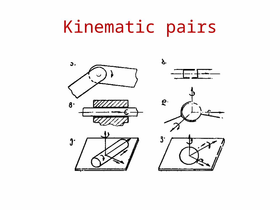
The inverse geometrical task
Values of angular velocities
0 2 4 6 8 10 12 14 16 18 20-2
-1
0
1
t
ffi0
1 kuTxur i si Cqar eebi
0 2 4 6 8 10 12 14 16 18 20-0.5
0
0.5
t
ffi1
2

The inverse geometrical task
0 2 4 6 8 10 12 14 16 18 20-0.5
0
0.5
1
t
ffi3
4
0 2 4 6 8 10 12 14 16 18 20-0.4
-0.2
0
0.2
0.4
t
ffi4
0

The inverse geometrical task
Values of angular accelerations
0 2 4 6 8 10 12 14 16 18 20-10
0
10
20
30
t
fffi01
kuTxur i aCqar ebebi
0 2 4 6 8 10 12 14 16 18 20-30
-20
-10
0
10
t
fffi12

The inverse geometrical task
0 2 4 6 8 10 12 14 16 18 20-0.4
-0.2
0
0.2
0.4
t
fffi3
4
0 2 4 6 8 10 12 14 16 18 20-1
-0.5
0
0.5
t
fffi4
0

Kinetostatics of five bar planar mechanisms
On the links of mechanical system are acting two type of force factors - External forces and Internal forces.
The internal forces – forces of weight, reduction forces of inertia and moments of inertia of force couples
Forces of inertia-Moments of inertia of force couples-
slus WmF
2
zsus IM

Kinetostatics of five bar planar mechanism
Reduction forces and moments of inertia acting on the links of five bar mechanism

Determination of forces and torques
Lagrange equation relatively to generalized
coordinate
Lagrange equation relatively to generalized coordinate
111
DMTT
dt
d
444
DMTT
dt
d
4
4

Determination of forces and torques
Equitant for determination of torque acting on A kinematic pair.
124
1
44
4
14
414
1121
1
11414
111
2
1
2
1
DMII
II
dt
dI
dt
dI
Equitant for determination of torque acting on O kinematic pair.
421
4
11
1
14
411
4424
4
44114
441
2
1
2
1
DMII
II
dt
dI
dt
dI

Determination of force factors
0 2 4 6 8 10 12 14 16 18 20-10
0
10
20
30
40
50
60
70
80
90
t
M1p
Determination of torque acting on A kinematic pair.

Determination of force factors
0 2 4 6 8 10 12 14 16 18 20-3
-2
-1
0
1
2
3
t
M4p
Determination of torque acting on O kinematic pair.

Thank you


![A novel six-degrees-of-freedom series-parallel … · A novel six-degrees-of-freedom series-parallel manipulator ... Kutzbach criterion [19], is capable to realize six degrees of](https://img.dokumen.tips/doc/110x75/5b79f3c77f8b9a703b8ebdd5/a-novel-six-degrees-of-freedom-series-parallel-a-novel-six-degrees-of-freedom.jpg)