Embed Size (px)
Citation preview

Geometry-based Muscle Modeling for Facial Animation
Kolja Kahler Jorg Haber Hans-Peter Seidel
Max-Planck-Institut fur Informatik, Stuhlsatzenhausweg 85, 66123 Saarbrucken, Germanykaehler,haberj,[email protected]
AbstractWe present a muscle model and methods for muscleconstruction that allow to easily create animatable facialmodels from given face geometry. Using our editing tool,one can interactively specify coarse outlines of the mus-cles, which are then automatically created to fit the facegeometry.
Our muscle model incorporates different types of mus-cles and the effects of bulging and intertwining musclefibers. The influence of muscle contraction onto the skinis simulated using a mass-spring system that connects theskull, muscle, and skin layers of our model.
Key words: physics-based facial animation, muscle / skinmodel, muscle editor, mass-spring system
1 Introduction
Recently, the development of more and more accuratesimulation of human characters based on their anatomyhas led toanatomically based modelingas the bottom-up approach for building characters from bones, muscles,and skin.
For human faces, however, this approach is unsuitableif the target geometry is already given. Since the mus-cles of the face lie closely underneath the skin and havea great influence on the shape and appearance of the sur-face, it is difficult to model the skin from skull and mus-cles in such a way that the result bears close resemblancewith the target face. On the other hand, surface geometrycan easily be acquired using for instance a range scanner.Thus, our approach is to adapt the muscle geometry to theprescribed facial geometry.
To facilitate this task, we have developed an interactivemuscle editor, which is depicted in Figure 14. The usercan roughly sketch a layout of facial muscles, which arethen automatically fitted to the given face mesh.
2 Previous Work
Techniques for animating human beings and human facesin particular have been an active area of research sincethe early 1980’s [18, 15]. Apart from some recent image-based techniques [17, 1] and methods that apply previ-ously captured facial expressions to a face model [8], the
methods developed so far can be divided into two cate-gories: parametric and physics-based models [16].
Parametric models control the shape of the skin by di-rectly manipulating the geometry of the surface [15, 4].WATERS [24] presented a muscle model which uses mus-cle vectors and radial functions derived from linear andsphincter muscles to deform a skin mesh. CHADWICK
et al. [2] use free-form deformations to shape the skinin a multi-layer construction containing bones, muscles,fat tissue, and skin. A B-Spline surface model has beenused by NAHAS et al. [14] to generate synthetic visualspeech, while a variational approach is presented by DE-CARLO et al. [6] to generate novel synthetic face mod-els using anthropometric statistics. The MPEG-4 stan-dard [9] specifies a set of 68 facial animation parame-ters (FAPs) which can be applied to any suitable headmodel. GOTO et al. [7] use these FAPs to control theirfacial animation system. Though parametric models canbe applied at relatively low computational costs, realisticblending between facial expressions is problematic [25].Also, the range of possible skin deformations is limited.
Physics-based models typically use mass-spring or fi-nite element networks to model the (visco-)elastic prop-erties of skin [18, 12, 11]. WATERS and FRISBIE [25]proposed a two-dimensional mass-spring model of themouth with the muscles represented as bands. A three-dimensional model of the human face has been devel-oped by TERZOPOULOSand WATERS [21]. Their modelconsists of three layers (cutaneous tissue, subcutaneousfatty tissue, and muscles) that are embedded in a mass-spring system. Due to additional volume preservationconstraints, this approach produces realistic results suchas wrinkling at interactive frame rates. A framework forfacial animation based on a simplified version of thismodel was presented by LEE et al. [13]. Their tissuemodel consists of two layers (dermal-fatty and muscles)and is connected by springs to a skull structure that is es-timated from the surface data. The mass-spring systemused in this approach also considers volume preservationand skull penetration constraints. The face model de-signed by WU et al. focuses on the viscoelastic propertiesof skin: muscles are represented by surfaces of revolu-tion [28] or B-spline patches [27], which can be specified

Figure 1: Generic skull model fitted to head using affinetransformation for estimating assignment of skin regionsto skull and jaw.
Figure 2: Head model prepared from scan data (left), cutup and simplified to represent the skull (right).
interactively. Their model is able to generate expressivewrinkles and skin aging effects. CHEN and ZELTZER [3]developed a finite element muscle model to simulate thedeformation of individual muscles without an overlyingskin tissue. Recently, SCHEEPERSet al. [19] and WIL -HELMS and VAN GELDER [26] presented anatomy-basedmuscle models for animating humans and animals. Theirmodels incorporate skeletal bones and joints as well asmuscle geometry. However, the skin tissue is representedonly by an implicit surface with zero thickness [26].
3 Our Approach
Our model for muscle-based facial animation uses threeconceptual layers:
• a skin / tissue layer representing the epidermis andsubcutaneous fatty tissue;
• a layer of muscles attached to the skull and insertinginto the skin;
• the underlying bone structure, composed of immov-able skull and rotating jaw.
Our input data consists of an arbitrary triangle meshrepresenting the skin geometry, which is typically ob-tained from a range scanner. The skull geometryand the layout of the facial muscles are created semi-automatically, based on the face mesh. Animation of theface is achieved by physics-based simulation of a mass-spring system that connects the three layers of our model.
3.1 Skull and JawSince we operate on models acquired from range data,we don’t have access to the actual skull geometry. In-stead, we use approximations of skull and jaw to whichskin surface nodes and muscles are attached. Other thanby computing a single offset surface [13], we distinguishbetween the fixed part of the skull and the movable jaw.
We use the skull and jaw meshes to determine whethera part of the skin and muscle layers lies over the skullor over the jaw. For the latter, that part will follow therotation of the jaw.
If a skull model is available, it can be aligned to thegeometry by affine transformations. While it is generallynot possible to match a generic skull to different humanheads in this way, the approximation is good enough forassigning skin regions to skull or jaw, see Figure 1. Al-ternatively, an approximated skull model is obtained bycutting up the original input mesh, roughly separating thejaw from the rest of the head (cf. Figure 2). A standardmesh simplification algorithm [10] is applied, since wefound that a coarse approximation of the bone structureis sufficient. Finally, the simplified geometry is scaleddown (by a small offset determined by the skin thickness)and placed inside the head model. This approach is nec-essary for synthetic heads which have no real anatomicalcounterpart, see for instance Figure 13. The same skullmodel can be used without further work for multiple vari-ations of the original head geometry, such as low and highresolution versions, or minor changes in facial details.
The skull and jaw meshes are used only while inter-actively building muscles in the editor and during thestartup phase of the animation system. They are not usedduring the runtime of an animation, since skull penetra-tion constraints are handled internally to the mass-springmesh, cf. Section 3.3.
3.2 Muscles
Our muscle model is based on a piecewise linear repre-sentation similar to the one developed by LEE et al. [13],where isotonic contraction is expressed by shortening thelinear segments. A muscle can either contract towardsthe end attached to the skull (linear muscle) or towardsa point (circular muscle). In our model, each of thesegments is additionally assigned an ellipsoidal shape.

Figure 3: Different types of muscles supported by ourmodel: linear (1), sheet (2), curved (3), and sphincter (4)muscles (original image from [20]).
The piecewise linear muscle “fibers” can be combinedinto groups to formsheet muscles. Implicit surfaces forspecifying the shape of muscles have been used before:SCHEEPERSet al. [19] also arrange ellipsoids to formmore complex muscles. Their “general muscle model”uses bicubic patches, whereas our structure is composedof quadric segments. For construction of the muscleswe need to perform operations on the segments that arereadily available in the quadric representation: ray in-tersection tests, normal computation, and inside / outsidetests [5]. For computation of deformed muscle shapesduring animation only affine invariance is needed, soother segment shapes could be used efficiently as well.
Using this model, we can lay out muscles in the variousconfigurations that appear in the human face: long andthin strands (zygomatic major) as well as broad sheets(frontalis), curved muscles (levator labii sup. alaequenasii), and sphincters (orbicularis oris, though this mus-cle is in fact built from segments but usually approxi-mated as a sphincter), see Figure 3.
Muscles are often layered, sliding freely across eachother. As WATERS and FRISBIE point out [25], musclesmay also intertwine and merge so that their actions arecoupled, a fact that can be observed especially in the re-gion around the mouth. In our model, muscles can mergein this way and move other muscles. To make for instancethe lower part oforbicularis oris follow the rotation ofthe jaw when the mouth is opened, muscles can be at-tached to either the immovable skull or the rotatable jaw .We also follow WATERSand FRISBIE in that the musclesdrive the animation and are not in turn moved by the skin.In reality, theorbicularis orisis pulled downwards by theskin when the jaw opens.
skin meshmuscle layer
skull layermirroredskull / muscleattachments
Figure 4: Mass-spring system in our model. Top: Re-laxed muscle, outer springs mirroring skull and muscleattachments. Bottom: Contracted muscle, with masspoints moving due to the contraction marked by .
3.3 Skin and Tissue SimulationThe top layer of our model represents the skin. Currentlywe model elastic properties of the dermis and epidermisand the fatty layer underneath. The skin layer connects tomuscles and bones, see Figure 4.
The nodes and edges of the input triangle mesh com-prise the initial spring mesh. These springs are bipha-sic, i.e. they become stiffer under high strain, to roughlymimic the non-linear elastic properties of skin. The ini-tial stiffness constants are computed according to VAN
GELDER [22].Each surface node is connected to either the bone layer
or to an underlying muscle by a spring with low stiffness,simulating the fatty subcutaneous layer that allows skinto slide freely.
When the skin mesh is modeled as a simple mem-brane, it may penetrate the muscle and bone layers whenstretched. Also, the mesh can easily fold over. Meth-ods for local volume preservation and skull penetrationconstraints have already been proposed in [13]. We com-bine both requirements into one and attach another springto each mesh node that pulls the nodeoutwards, mirror-ing the spring that attaches it to the bone layer (cf. Fig-ure 4). This can be interpreted as a model of the outward-directed force resulting from the internal pressure of askin cell. Similarly, springs are added to mirror muscleattachments. However, these mirrored spring nodes movealong with their counterparts when the muscle contracts.Thus a surface node preferably moves in a direction tan-gential to the skull and muscle surface. Thereby intersec-tions are avoided in practice though not completely ruledout – violent distortion can still cause intersections. Anice property of this mechanism is the seamless integra-

p21
p
4
p3
pp
0
Figure 5: Muscle fiber with control polygon P = piand per-segment ellipsoids.
tion into the spring mesh system: no special treatment ofadditional constraints is needed.
The equations of motion for the mass-spring systemare numerically integrated through time using an explicitforward integration scheme (Verlet leapfrog [23]). Tomaximize stability, we measure the computation time forone time step of the simulation. The step size is dynam-ically adjusted to run as many small steps as possiblein the time slot between two rendered frames, as deter-mined by the given frame rate. In addition, we use anover-relaxation scheme to speed up the convergence ofour simulation. This is accomplished by displacing thesurface nodes to their estimated final position before in-voking the solver. The estimation is based on muscle con-traction and jaw rotation.
4 Muscle Model Details
Muscles are built from individual fibers that are in turncomposed of piecewise linear segments. A quadric shape(ellipsoid) is aligned to each of these segments and scaledto the length of the muscle segment. The width and heightof each ellipsoid correspond to the extent of the muscleparallel and orthogonal to the skin surface, respectively.
The initial description of a muscle fiber consists ofncontrol pointspi ∈ R3 (i = 0, . . . , n− 1) forming acontrol polygonP as shown in Figure 5.
4.1 ContractionGiven a contraction valuec ∈ [0, 1], wherec = 0 meansno contraction andc = 1 full contraction, a new controlpolygon Q = qin−1
i=0 is computed (cf. Figure 6).Each control pointpi ∈ P is assigned a parameterti ∈
[0, 1]:
ti :=
0 , if i = 0,∑ij=1 ‖pj−pj−1‖∑n−1j=1 ‖pj−pj−1‖
, else.
The parametersti are scaled by the contraction factor1−c and clamped to[0.01, 1] to avoid shrinking a segmenttoo much:
ti := max(1−c)ti, 0.01.
Next, we map each parameterti to the indexki ∈0, . . . , n−2 of the starting point of the segment that
0 6pp
3
q12
6qq
0*p==
q
q0
1q 2
43
p
1p
0p p
4
3p
2
q
1p
p
p3
4p
p2
5q q
4
5
q
Figure 6: Contraction (c = 12 ) of a linear (top) and a
sphincter (bottom) muscle fiber. The control points piand qi represent the relaxed and contracted muscle.
containsti:
ki :=
0 , if i = 0,m : tm < ti ≤ tm+1 , else.
Finally, we compute the new control pointsqi by linearinterpolation:
qi := pki + (pki+1 − pki)ti − tki
tki+1 − tki.
For sphincter muscles, segments are simply contractedtowards a center pointp∗ ∈ R3:
qi := p∗ + (1− c)(pi − p∗).
4.2 BulgeReal muscles get thicker on contraction and thinner onelongation. Simulating this behavior enhances visual re-alism: when the face smiles, the lips retract slightly asthey stretch. On the other hand, the lips get a little thicker,when the mouth forms an “o” or a kiss (cf. Figure 15).
For linear muscles, we want the center of the musclesto exhibit the highest bulge, corresponding to the belly ofreal muscles. Sphincters bulge evenly, see Figure 7.
In our model, bulging is achieved by scaling the heightof each muscle segmentpi pi+1 by (1 + 2si). Here,si ∈[0, 1] denotes the scaling factor computed from the lengthlri = ‖pi+1 − pi‖ of the relaxed muscle and its currentlengthlci = ‖qi+1− qi‖: si := 1− lci/lri . This results ina center segment of triple height at maximum contraction.
For each linear muscle with at least three segments, weadditionally multiply si by a simple quadratic function
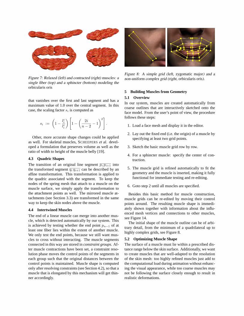
Figure 7: Relaxed (left) and contracted (right) muscles: asingle fiber (top) and a sphincter (bottom) modeling theorbicularis oris
that vanishes over the first and last segment and has amaximum value of 1.0 over the central segment. In thiscase, the scaling factorsi is computed as
si :=(
1− lcilri
)[1−
(2i
n− 2− 1)2].
Other, more accurate shape changes could be appliedas well. For skeletal muscles, SCHEEPERSet al. devel-oped a formulation that preserves volume as well as theratio of width to height of the muscle belly [19].
4.3 Quadric Shapes
The transition of an original line segmentpi pi+1 intothe transformed segmentqi qi+1 can be described by anaffine transformation. This transformation is applied tothe quadric associated with the segment. To keep thenodes of the spring mesh that attach to a muscle on themuscle surface, we simply apply the transformation tothe attachment points as well. The mirrored muscle at-tachments (see Section 3.3) are transformed in the sameway to keep the skin nodes above the muscle.
4.4 Intertwined Muscles
The end of a linear muscle can merge into another mus-cle, which is detected automatically by our system. Thisis achieved by testing whether the end pointpn−1 of atleast one fiber lies within the extent of another muscle.We only test the end points, because we still want mus-cles to cross without interacting. The muscle segmentsconnected in this way are stored inconstraint groups. Af-ter muscle contractions have been set, a constraint reso-lution phase moves the control points of the segments ineach group such that the original distances between thecontrol points is maintained. Muscle shape is computedonly after resolving constraints (see Section 4.2), so that amuscle that is elongated by this mechanism will get thin-ner accordingly.
Figure 8: A simple grid (left, zygomatic major) and anon-uniform complex grid (right, orbicularis oris).
5 Building Muscles from Geometry
5.1 OverviewIn our system, muscles are created automatically fromcoarse outlines that are interactively sketched onto theface model. From the user’s point of view, the procedurefollows these steps:
1. Load a face mesh and display it in the editor.
2. Lay out the fixed end (i.e. the origin) of a muscle byspecifying at least two grid points.
3. Sketch the basic muscle grid row by row.
4. For a sphincter muscle: specify the center of con-traction.
5. The muscle grid is refined automatically to fit thegeometry and the muscle is inserted, making it fullyfunctional for immediate testing and re-editing.
6. Goto step 2 until all muscles are specified.
Besides this basic method for muscle construction,muscle grids can be re-edited by moving their controlpoints around. The resulting muscle shape is immedi-ately shown together with information about the influ-enced mesh vertices and connections to other muscles,see Figure 14.
The initial shape of the muscle outline can be of arbi-trary detail, from the minimum of a quadrilateral up tohighly complex grids, see Figure 8.
5.2 Optimizing Muscle ShapeThe surface of a muscle must lie within a prescribed dis-tance range below the skin surface. Additionally, we wantto create muscles that are well-adapted to the resolutionof the skin mesh: too highly refined muscles just add tothe computational load during animation without enhanc-ing the visual appearance, while too coarse muscles maynot be following the surface closely enough to result inrealistic deformations.

Given the skin mesh and a muscle grid, our optimiza-tion step determines the following parameters that areneeded to create the muscles:
• the number of muscle fibers;
• the number of segments per fiber;
• width, height, and length of each segment;
• position of the muscle fiber control points;
• alignment of the quadrics’ coordinate systems.
In addition to the regular grid, the skin thicknessτ s,which is assumed to be constant over the whole face, andthe minimum and maximum muscle layer thicknessτmminand τmmax are input parameters of the optimization step.These parameters can be adjusted by the user based onthe input geometry.
A muscle is created from its grid by a four-step proce-dure:
1. Initializing the grid. The initial outline is con-verted into a regular grid, i.e. all rows are assignedthe same number of grid points. The grid pointsare then projected onto the face mesh and placedslightly underneath the skin surface.
2. Refining the grid. The grid is adaptively refineduntil a decent approximation has been found.
3. Creating the muscle.Muscle fibers are createdand aligned to the refined grid.
4. Attaching the muscle. The muscle is attached tothe spring mesh, and the control points of the musclesegments are attached to either the skull or the jaw.
Details of these steps are explained in the following sec-tions.
5.3 Initializing the GridTo obtain a regular grid, we first determine the maximumnumbernmax of grid points per row. Then, additional gridpoints are inserted by linear interpolation into every rowthat contains less thannmax points.
We now estimate normals at the grid points. For thevarious grid layouts we obtained best results by first com-puting the normal of the balancing plane through the fourcorner points of each grid cell and than averaging the nor-mals of all adjacent cells at each grid point.
Having computed the grid point normals, we find thetriangles of the face mesh that intersect the projection ofthe grid onto the skin surface and cache them for fastlookup during the iterative refinement procedure. Theinitial grid points are now displaced along their normal
direction to lie below the skin in an initial distance ofτ s+(τmmin +τmmax)/4, representing the middle of a muscleof average thickness running through the cell.
5.4 Refining the GridThe fitting algorithm proceeds by sampling the distancesfrom each cell to the skin surface. Each cell is exam-ined and subdivided if necessary. The grid points are thenagain displaced to lie within the prescribed distance rangebelow the surface. Simultaneously, the cell thickness isadjusted within the boundsτmmin andτmmax. This process isrepeated until no more subdivisions are necessary or canbe applied.
The main loop of this iteration is organized as follows:
repeatfor each grid cell c
( dmin , dmax, pnear , pfar ) =minMaxDistancesToMesh( c);
( enear , efar ) =minMaxError( dmin , dmax, τ s, τmmin , τmmax);
if ( enear == 0 and efar == 0)c.thickness = 2( dmin - τ s)
else if ( efar > enear )trySubdivisionAtPoint( c, pfar );
elsetrySubdivisionAtPoint( c, pnear );
moveNewGridPoints();until no more changes to grid.
The procedureminMaxDistancesToMesh() re-turns two pointspnear,pfar that are nearest to and farthestaway from the cell in the following sense: we adaptivelysubsample the grid cell and shoot a ray from each sampleposition in the direction of the associated bilinearly inter-polated grid normal vector. The base points of the rayswith the nearest and farthest intersection points with thecached surface area are returned aspnear andpfar alongwith their signed distance valuesdmin and dmax. Bothpoints can be positioned below (positive distance value)or above the skin surface (negative value), see Figure 9.The sampling density over the grid cell adjusts to the sizeof the cell and the number of cached triangles to ensure aminimum number of samples per triangle.
The error valuesenear and efar that are computed byminMaxError() represent the unsigned distancespnear
andpfar would have to move along their grid normal to bein the allowed range of distances[τ s + τmmin, τ
s + τmmax]below the skin surface (see Figure 10). Also, if|dmax−dmin| > τmmin, the distance from the cell to the skin varieswidely over the cell area, so that there is enough spacefor insertion of a thin muscle. In this case,(enear, efar) areset to(|dmin|, |dmax|), causing a subdivision of the cell inthe next step.

G′
M
pnear
dmax > 0
pfar
M
G
dmin < 0
Figure 9: Refinement step for a single grid cell (simpli-fied two-dimensional view). Top: Points of grid G havebeen placed below the skin mesh M along their associ-ated normals. The closest point of the grid cell lies above,the farthest point lies below the skin mesh. Bottom: Ghas been subdivided at the point of larger error enear (seealso Figure 10).
The proceduretrySubdivisionAtPoint() iscalled with the sample position corresponding to the pointwith the larger error. A new row and/or column throughthat position is inserted into the grid. Before subdividinga cell along one of its dimensions, we compare the sizesof the resulting sub-cells with the average extent of thecached triangles in that direction. If the sub-cells wouldget too small, the insertion point is adjusted to make bothparts big enough. If the cell is already too small to al-low for adjustment, no subdivision along this direction isperformed.
Finally, in moveNewGridPoints() the grid pointsinserted by subdivision are projected onto the surfacemesh and displaced byτ s + (τmmin + τmmax)/4 underneaththe skin.
5.5 Creating the MuscleAfter a grid has been refined sufficiently, we build a sheetof muscle fibers. One muscle fiber is inserted longitudi-nally into each stripe of grid cells, creating one musclesegment per cell. The size of each ellipsoid is scaled tofill the surrounding cell, whereas width and length of inte-rior ellipsoids are slightly enlarged to provide some over-lap across cell boundaries. Figure 11 shows the creationof a sheet muscle from a simple grid.
5.6 Attaching the Muscle to SkinMuscles have to be connected to the spring mesh, so thatcontraction will influence nearby skin vertices. We con-
τmmax
τ s τmmin
pfar (efar = 0)
pnear(enear> 0)
Figure 10: The range of thickness for muscle shapes: be-low the skin layer of constant thickness τ s muscles can beinserted with a thickness in the range [τmmin, τ
mmax]. Error
values for two exemplary points are shown: pnear is out-side the allowed range for muscle segments and shouldbe moved upwards (enear > 0). pfar is within range andneed not be moved (efar = 0).
sider the vertices within a specified radius of influencefrom the muscle fibers as candidates for muscle attach-ment: for each of these skin nodes, we compute the clos-est point on the surface of all quadrics comprising themuscle sheet and insert a spring connecting the skin nodewith that point. An additional spring is created as de-scribed in Section 3.3 by mirroring the attachment point.
There are special cases where the distance-based com-putation of attachment points is not sufficient. For in-stance, when the face mesh has a closed mouth, verticesalong the cut separating the upper and lower lip will havealmost – if not exactly – the same coordinates. Thesevertices may thus be attached to the muscles around theupper and lower lips in a nondeterministic way. This willlikely cause the upper lip to move along with the lowerorbicularis orisand vice versa. To solve this problem, weweight the distance value of each skin node with the dotproductNsNd, whereNs is the surface normal at the skinvertex andNd is the normalized vector pointing from thepotential attachment point to that vertex. Thereby mus-cle segments that lie directly below the skin vertex arefavored.
5.7 Attaching the Muscle to Skull and JawTo find out whether a muscle control point should movealong with the jaw or remain fixed, we shoot rays fromthe grid points along their normals through the skin meshand examine the attachment of the closest skin vertex inthe hit triangle. If the majority of points in a grid row isclosest to skull-attached skin vertices, the correspondingmuscle attachments will also be fixed. Otherwise, mus-cles will be attached to the jaw, if the closest skin verticesare mostly assigned to the jaw.
Not all regions of the face have bones underneath, e.g.the lips and the cheeks. Skin vertices in these regions arethus not attached to the bone structure. To decide aboutthe muscle attachment in these cases, we iteratively grow
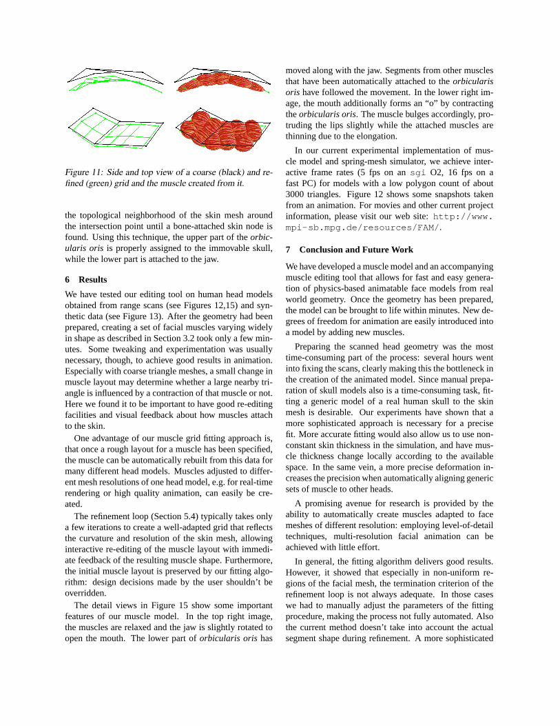
Figure 11: Side and top view of a coarse (black) and re-fined (green) grid and the muscle created from it.
the topological neighborhood of the skin mesh aroundthe intersection point until a bone-attached skin node isfound. Using this technique, the upper part of theorbic-ularis oris is properly assigned to the immovable skull,while the lower part is attached to the jaw.
6 Results
We have tested our editing tool on human head modelsobtained from range scans (see Figures 12,15) and syn-thetic data (see Figure 13). After the geometry had beenprepared, creating a set of facial muscles varying widelyin shape as described in Section 3.2 took only a few min-utes. Some tweaking and experimentation was usuallynecessary, though, to achieve good results in animation.Especially with coarse triangle meshes, a small change inmuscle layout may determine whether a large nearby tri-angle is influenced by a contraction of that muscle or not.Here we found it to be important to have good re-editingfacilities and visual feedback about how muscles attachto the skin.
One advantage of our muscle grid fitting approach is,that once a rough layout for a muscle has been specified,the muscle can be automatically rebuilt from this data formany different head models. Muscles adjusted to differ-ent mesh resolutions of one head model, e.g. for real-timerendering or high quality animation, can easily be cre-ated.
The refinement loop (Section 5.4) typically takes onlya few iterations to create a well-adapted grid that reflectsthe curvature and resolution of the skin mesh, allowinginteractive re-editing of the muscle layout with immedi-ate feedback of the resulting muscle shape. Furthermore,the initial muscle layout is preserved by our fitting algo-rithm: design decisions made by the user shouldn’t beoverridden.
The detail views in Figure 15 show some importantfeatures of our muscle model. In the top right image,the muscles are relaxed and the jaw is slightly rotated toopen the mouth. The lower part oforbicularis oris has
moved along with the jaw. Segments from other musclesthat have been automatically attached to theorbicularisoris have followed the movement. In the lower right im-age, the mouth additionally forms an “o” by contractingtheorbicularis oris. The muscle bulges accordingly, pro-truding the lips slightly while the attached muscles arethinning due to the elongation.
In our current experimental implementation of mus-cle model and spring-mesh simulator, we achieve inter-active frame rates (5 fps on ansgi O2, 16 fps on afast PC) for models with a low polygon count of about3000 triangles. Figure 12 shows some snapshots takenfrom an animation. For movies and other current projectinformation, please visit our web site:http://www.mpi-sb.mpg.de/resources/FAM/ .
7 Conclusion and Future Work
We have developed a muscle model and an accompanyingmuscle editing tool that allows for fast and easy genera-tion of physics-based animatable face models from realworld geometry. Once the geometry has been prepared,the model can be brought to life within minutes. New de-grees of freedom for animation are easily introduced intoa model by adding new muscles.
Preparing the scanned head geometry was the mosttime-consuming part of the process: several hours wentinto fixing the scans, clearly making this the bottleneck inthe creation of the animated model. Since manual prepa-ration of skull models also is a time-consuming task, fit-ting a generic model of a real human skull to the skinmesh is desirable. Our experiments have shown that amore sophisticated approach is necessary for a precisefit. More accurate fitting would also allow us to use non-constant skin thickness in the simulation, and have mus-cle thickness change locally according to the availablespace. In the same vein, a more precise deformation in-creases the precision when automatically aligning genericsets of muscle to other heads.
A promising avenue for research is provided by theability to automatically create muscles adapted to facemeshes of different resolution: employing level-of-detailtechniques, multi-resolution facial animation can beachieved with little effort.
In general, the fitting algorithm delivers good results.However, it showed that especially in non-uniform re-gions of the facial mesh, the termination criterion of therefinement loop is not always adequate. In those caseswe had to manually adjust the parameters of the fittingprocedure, making the process not fully automated. Alsothe current method doesn’t take into account the actualsegment shape during refinement. A more sophisticated

approach would probably lead to better approximationsof the skin curvature with fewer muscle segments.
The muscle model itself performs well with low com-putational overhead. We think it would be worthwhile toadd elastic behavior to the muscles themselves, thus al-lowing them to straighten under tension (contraction andelongation) and producing more realistic deformations ofmerged muscles.
Acknowledgements
The authors are grateful to their “head model” MarioBotsch and to Christian Rossl for operating the rangescanner.
References[1] V. Blanz and T. Vetter. A Morphable Model for the Syn-
thesis of 3D Faces. InComputer Graphics (SIGGRAPH’99 Conf. Proc.), pages 187–194, August 1999.
[2] J. E. Chadwick, D. R. Haumann, and R. E. Parent. Lay-ered Construction for Deformable Animated Characters.In Computer Graphics (SIGGRAPH ’89 Conf. Proc.),pages 243–252, July 1989.
[3] D. T. Chen and D. Zeltzer. Pump it up: Computer Anima-tion of a Biomechanically Based Model of Muscle usingthe Finite Element Method. InComputer Graphics (SIG-GRAPH ’92 Conf. Proc.), pages 89–98, July 1992.
[4] M. M. Cohen and D. W. Massaro. Modeling Coarticu-lation in Synthetic Visual Speech. InModels and Tech-niques in Computer Animation, pages 139–156. Springer–Verlag, 1993.
[5] J. M. Cychosz and W. N. Waggenspeck, Jr. Intersecting aRay with a Quadric Surface. InGraphics Gems III, pages275–283. Academic Press, London, 1992.
[6] D. DeCarlo, D. Metaxas, and M. Stone. An Anthropo-metric Face Model using Variational Techniques. InCom-puter Graphics (SIGGRAPH ’98 Conf. Proc.), pages 67–74, July 1998.
[7] T. Goto, M. Escher, C. Zanardi, and N. Magnenat-Thalmann. MPEG-4 based Animation with Face FeatureTracking. InProc. Eurographics Workshop on ComputerAnimation and Simulation ’99, pages 89–98, 1999.
[8] B. Guenter, C. Grimm, D. Wood, H. Malvar, and F. Pighin.Making Faces. InComputer Graphics (SIGGRAPH ’98Conf. Proc.), pages 55–66, July 1998.
[9] ISO/IEC. Overview of the MPEG-4 Standard.http://www.cselt.it/mpeg/standards/mpeg-4/mpeg-4.htm , July 2000.
[10] L. Kobbelt, S. Campagna, and H.-P. Seidel. A GeneralFramework for Mesh Decimation. InProc. Graphics In-terface ’98, pages 43–50, June 1998.
[11] R. M. Koch, M. H. Groß, and A. A. Bosshard. EmotionEditing using Finite Elements. InComputer Graphics Fo-rum (Proc. Eurographics ’98), volume 17, pages C295–C302, September 1998.
[12] Y. Lee, D. Terzopoulos, and K. Waters. ConstructingPhysics-based Facial Models of Individuals. InProc.Graphics Interface ’93, pages 1–8, May 1993.
[13] Y. Lee, D. Terzopoulos, and K. Waters. Realistic Model-ing for Facial Animations. InComputer Graphics (SIG-GRAPH ’95 Conf. Proc.), pages 55–62, August 1995.
[14] M. Nahas, H. Huitric, and M. Saintourens. Animation ofa B-Spline Figure.The Visual Computer, 3(5):272–276,March 1988.
[15] F. I. Parke. Parameterized Models for Facial Animation.IEEE Computer Graphics and Applications, 2(9):61–68,November 1982.
[16] F. I. Parke and K. Waters, editors.Computer Facial Ani-mation. A K Peters, Wellesley, MA, 1996.
[17] F. Pighin, J. Hecker, D. Lischinski, R. Szeliski, and D. H.Salesin. Synthesizing Realistic Facial Expressions fromPhotographs. InComputer Graphics (SIGGRAPH ’98Conf. Proc.), pages 75–84, July 1998.
[18] S. M. Platt and N. I. Badler. Animating Facial Expres-sions. In Computer Graphics (SIGGRAPH ’81 Conf.Proc.), pages 245–252, August 1981.
[19] F. Scheepers, R. E. Parent, W. E. Carlson, and S. F. May.Anatomy-Based Modeling of the Human Musculature. InComputer Graphics (SIGGRAPH ’97 Conf. Proc.), pages163–172, August 1997.
[20] A. Szunyoghy and G. Feher. Menschliche Anatomie furKunstler. Konemann, Koln, 2000.
[21] D. Terzopoulos and K. Waters. Physically-based FacialModelling, Analysis, and Animation.Journal of Visual-ization and Computer Animation, 1(2):73–80, December1990.
[22] A. Van Gelder. Approximate Simulation of Elastic Mem-branes by Triangulated Spring Meshes.Journal of Graph-ics Tools, 3(2):21–41, 1998.
[23] F. J. Vesely. Computational Physics: An Introduction.Plenum Press, New York, 1994.
[24] K. Waters. A Muscle Model for Animating Three-Dimensional Facial Expression. InComputer Graphics(SIGGRAPH ’87 Conf. Proc.), pages 17–24, July 1987.
[25] K. Waters and J. Frisbie. A Coordinated Muscle Modelfor Speech Animation. InProc. Graphics Interface ’95,pages 163–170, May 1995.
[26] J. Wilhelms and A. Van Gelder. Anatomically BasedModeling. InComputer Graphics (SIGGRAPH ’97 Conf.Proc.), pages 173–180, August 1997.
[27] Y. Wu, P. Kalra, L. Moccozet, and N. Magnenat-Thalmann. Simulating Wrinkles and Skin Aging.TheVisual Computer, 15(4):183–198, 1999.
[28] Y. Wu, N. Magnenat-Thalmann, and D. Thalmann. APlastic-Visco-Elastic Model for Wrinkles in Facial Ani-mation and Skin Aging. InProc. Pacific Graphics ’94,pages 201–214, August 1994.
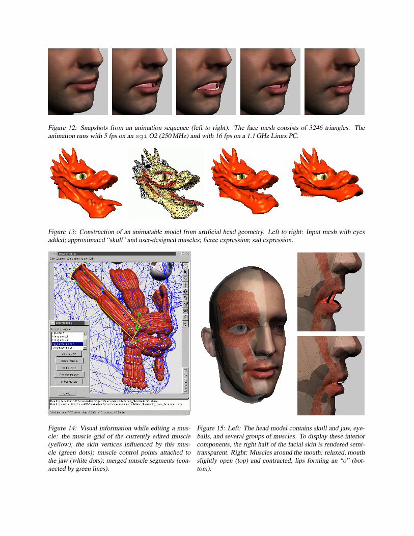
Figure 12: Snapshots from an animation sequence (left to right). The face mesh consists of 3246 triangles. Theanimation runs with 5 fps on an sgi O2 (250 MHz) and with 16 fps on a 1.1 GHz Linux PC.
Figure 13: Construction of an animatable model from artificial head geometry. Left to right: Input mesh with eyesadded; approximated “skull” and user-designed muscles; fierce expression; sad expression.
Figure 14: Visual information while editing a mus-cle: the muscle grid of the currently edited muscle(yellow); the skin vertices influenced by this mus-cle (green dots); muscle control points attached tothe jaw (white dots); merged muscle segments (con-nected by green lines).
Figure 15: Left: The head model contains skull and jaw, eye-balls, and several groups of muscles. To display these interiorcomponents, the right half of the facial skin is rendered semi-transparent. Right: Muscles around the mouth: relaxed, mouthslightly open (top) and contracted, lips forming an “o” (bot-tom).

ErrataThis electronic version of the document contains three corrections over the original version published in the proceedings of GraphicsInterface 2001:
page 4, right column, equation for sphincter contraction‖ · ‖ → (·)page 6, right column, line 2 τs + (τmmin + τmmax)/2 → τs + (τmmin + τmmax)/4page 7, left column, line 14 τs + (τmmin + τmmax)/2 → τs + (τmmin + τmmax)/4

![Mesoscopic Facial Geometry Inference Using Deep …chenweikai.github.io/papers/[CVPR18]Mesoscopic_Facial...Mesoscopic Facial Geometry Inference Using Deep Neural Networks Loc Huynh1](https://img.dokumen.tips/doc/110x75/5fd864642cd9f051e454ec2f/mesoscopic-facial-geometry-inference-using-deep-cvpr18mesoscopicfacial-mesoscopic.jpg)